

Page 1
Shure
Brothers Incorporated
222 Hartrey A
venue
Evanston IL 60202-3696 U.S.A.
Model M267 User Guide
GENERAL
The
S
hur
e M
ode
plifier
s
pecificall
y d
l M267 i
esigne
s a microphon
d for p
rofessiona
e m
ixer-remot
l a
pplications
e a
. T
m-
he
excellent performance, versatility and features of this com-
c
ompac
t c
onsol
plete,
o
mote,
r s
expanding
and v
audio
oun
e
ide
d r
xistin
e make i
einforcemen
g f
acilities
o tape r
ecorder
t a
n i
t use, and a
. I
t i
s also i
s t
o p
rovid
dea
deall
l c
s a
e m
hoic
n a
y s
ultipl
e for s
dd-o
uite
d for use w
e m
tudio
, r
n m
ixer for
icrophone
e-
ith
inputs.
Features:
• Wide,
•
•
• Feedback-type
•
• Built-in
flat frequency response and extremely low distor
up to +18 dBm output
tion
Extremely low noise and RF susceptibility
Four switchable microphone- or line-level balanced-line
with i
inputs
s
witches
off
levels
ndividua
. M
and dynamic range
l gain c
ontrol
s and l
ow-frequenc
UMET A
input
L s
hieldin
g o
n i
npu
t t
ransformers
gain controls for maximum clipping
y r
oll-
Output switchable for line or microphone level
switchable peak limiter cuts output overload
tortion,
adapts to power supply voltage
dis
• LED indicator shows limiter operation or overload with
defeated
limiter
•
Externally adjustable limiter threshold (–4 to +18 dBm)
• VU meter calibrated for +4 and +8 dBm with range
switch.
Illuminated with ac operation
• Ac or built-in battery operation. Noiseless automatic
switchover to battery in case of ac line failure. Battery
test
without program interruption
• Front-panel headphone level control and monitor jack
drives almost any stereo or mono headphones; output
be additional unbalanced line feed to drive
can
corder
or power amplifier
•
Direct mix bus for stacking units
a tape re
• Automatic muting prevents speaker damage during
turn-on
and -of
f
• Low distortion, high-stability tone oscillator for line test
and
level checks
• All
connections phased. Line
output terminals phase-in
dicated
• Compact and lightweight, with rugged, abrasion-resis case
tant
• Internally
selectable 120 or
240 V
ac, 50/60 Hz operation
• Underwriters’ Laboratories Listed and Canadian Stan-
Association listed as Certified
dards
SPECIFICATIONS
Frequency Response
-
30 Hz to 20,000 Hz, ±2 dB
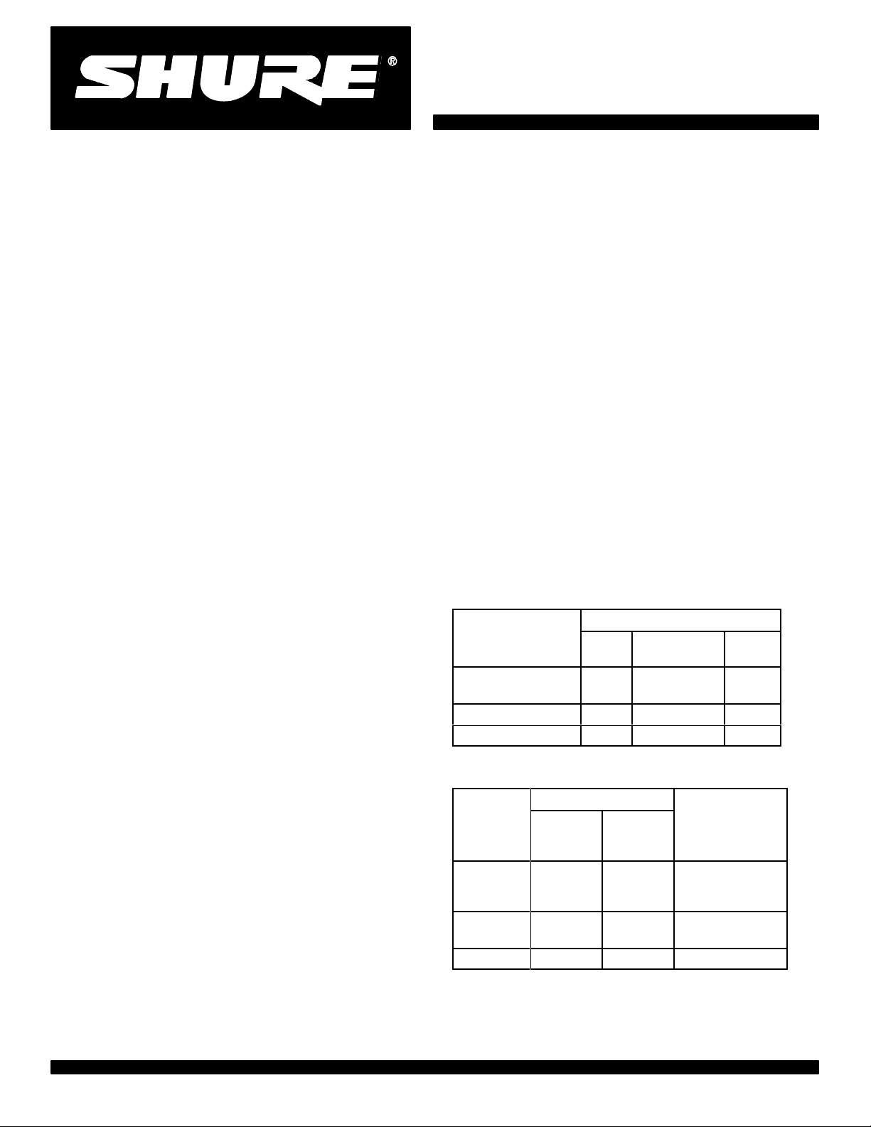
Voltage Gain
(at 1,000 Hz)
(Outputs terminated: line 600 microphone 150 mix
3.3 k
bus
Low-Impedance
-
Microphone (150
Line
Mix Bus
headphone 200 , tip-sleev
Input
Line Microphone Mix
91 dB 41 dB 24 dB
)
40 dB
55 dB
OUTPUT
–9 dB
5 dB
e and r
Inputs
IMPEDANCE
-
Designed
Input
M
icrophone
Line Less
Mix Bus
∗Depending
for Use
With
19 to 6
than10 k
3.5 k
on input control setting
00
Actual
(Internal)
1 k
66 k
3.5 k
Input
Clipping Level
–32 dB
5 d
BV∗
–
5 m
V t
(2
o 0.56 V
+20 dBV
+7 dBV (2.2 V)
ing-sleeve
Bus
–27 dB
– –
V t
o
-
)
)
1997, Shure Brothers Incorporated
27A8376
(QE)
Printed in U.S.A.
Page 2
Outputs
Headphone Output Clipping Level
IMPEDANCE
Designed for
Use W
Output
Microphone Any low imped-
anc
Mix Bus
Head
-
phones
recommended
Line
∗∗
Depending on level control setting
ith
e m
icrophone
input
3.5 k
8 - 2000
200
600 150
Actua
l
(Internal)
0.5
3.5 k
400
3 k ∗∗
Output
Clipping Level
–34 dB
0 m
(2
–8 dBV
(400 mV)
+10 dBV
(3.3 V)
+18
(6.2 V)
Noise
Equivalent Input Hum and Noise: –126 dBV (low
impedance
600 load
Output Noise
microphone, 150 - 20-20,000 Hz) into a
at full gain
: –75 dBV (
maste
r c
ontro
l f
ull
y c
clockwise), –53 dBV (master fully clockwise), (input
controls down
, 3
00-20,00
0 H
z)
Output Hum and Noise: –70 dBV (master control
down), –51 dBV (master control up) (input controls
2
down,
0-20,00
0 H
z)
Distortion
0.35% or less THD from 30 to 20,000 Hz at +15 dBm
output;
0.5% o
r less I
M d
istortio
n u
p t
o +15 dBm o
level
V)
dBm
ounter-
utput
3.16V (+10 dBV) into 200
T
one Oscillator
1,000 Hz, 1.5% or less THD
Phantom Power
30 Vdc open-circuit, 3.3 k series resistance, input
switches
Operating V
in MIC position only
oltage
Ac Operation: 120 or 240 volts ±10%, 50/60 Hz,
9.5W,
internally switchable
Dc
Operation:
27 volts nominal at 15
mA typical nosignal, 18 mA typical at 0 VU (+4 dBm) output with
headphone
Battery
teries
load; 21.5 volts minimum
life:
approximately 20 hours with alkaline
at +4 dBm output
in continuous use; three 9-volt
batteries, type NEDA 1604A (Duracell MN1604 recommended)
Supplied wired for 120 Vac operation (See Service section for
240
V
ac operation)
Temperature
Range
Operating: –18o to 57o C (0o to 135o F)
Storage: –29
o
to 71oC (–20o to 160o F)
bat
-
Common Mode Rejection
65 dB minimum with input of –20 dBV at 100 Hz
Control Interaction
Less than 1 dB with any control combination
Overload and Shorting Protection
Shorting the outputs, even for prolonged periods, will
cause no damage; microphone inputs will not be dam aged by s
ignal
s u
p t
o 3 v
olts
Lo-Cut Filters
6 dB/octave rollof
f at 150 Hz
Limiter
Threshold:
+15 dBm (line output level; adjustable
from –4 to +18 dBm)
Attack T
Recovery T
ime:
3 msec typical
ime:
500 msec typical
Peak Indicator
Lights
6 dB below clipping or at onset of limiter
action
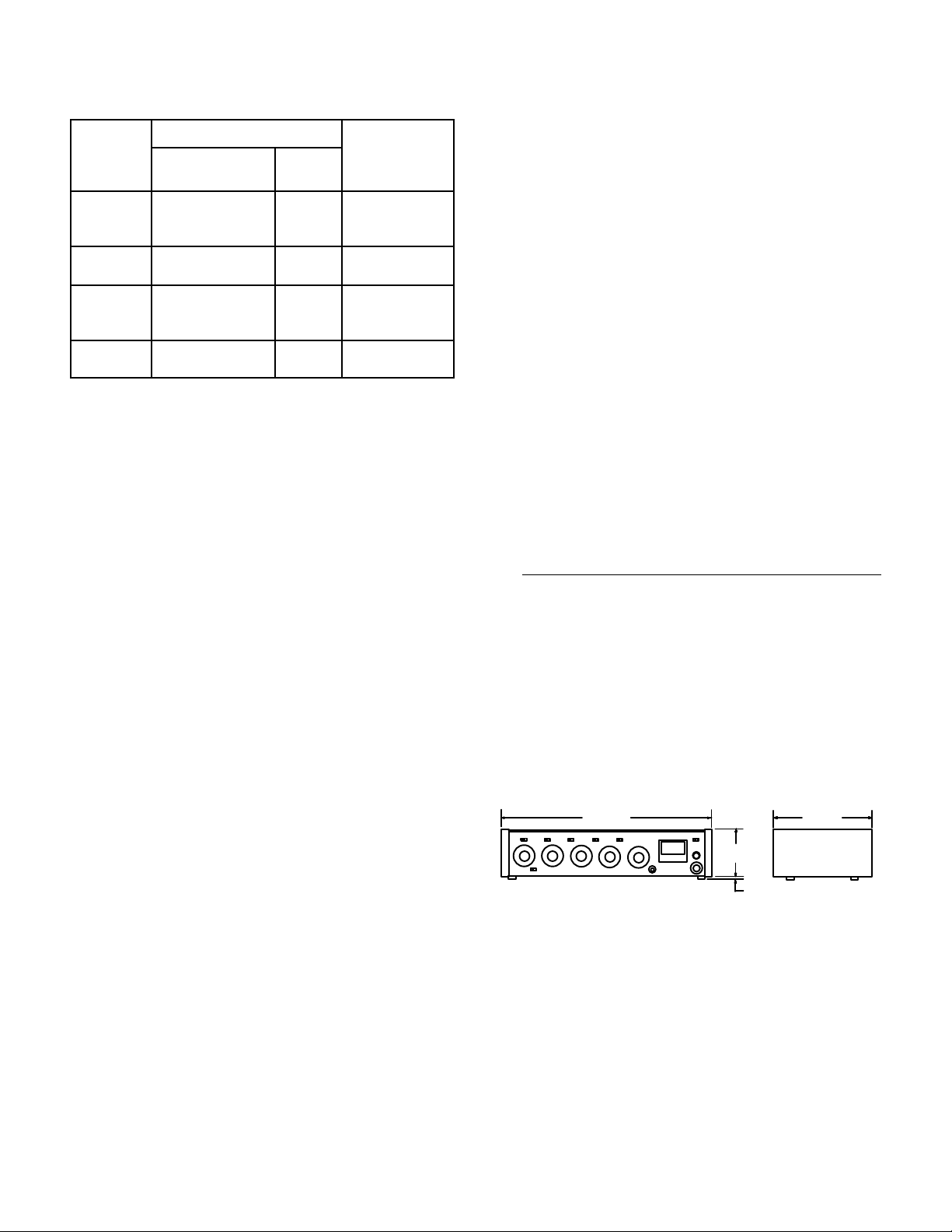
Dimensions
See Figure 1
Weight
Net: 2.3
Packaged:
Certifications
b
Listed
y U
Canadian
309
mm
5
(12
/
in.)
32
FIGURE 1
kg (5 lb 2 oz)
3.2 kg (7 lb 2 oz)
nderwriters
S
tandard
’ L
s A
ssociatio
68.8mm
23/32 in.)
(2
aboratories
n a
6.3 mm
(1/4 in. )
, I
s C
nc., an
ertified
229 mm
(9 in.)
d l
iste
d b
y
2
Page 3

CONTROLS AND CONNECT
ORS
WARNING
This
apparatus must be earthed (grounded)!
M267
power supply is energized when the unit
The
is
connected to an ac source; disconnect mains
(power)
plug from supply when not in use.
Inputs
The four inputs are professional three-pin female XLR
audio connectors located on the rear panel and designated
INPUT
1 through INPUT 4. The inputs are balanced
(internal transformer, MUMETAL shielded); pins 2 and 3
“hot”, and pin 1 is “ground”. For microphone operation,
are
the switches labeled LINE/MIC (directly above the input
connectors)
must be in the MIC position; for line level in
puts, the switches must be in the LINE position. For impedance,
clipping
SPECIFICATIONS
and operating signal levels, refer to the
section.
Outputs
The
rear-panel connector labeled OUTPUT is a
three-pin male XLR audio
sional
connector
. With the adja
profes
cent LINE/MIC switch in the MIC position, the OUTPUT
connector is used to feed a low-impedance microphone
or a low-impedance
line
microphone input. With the LINE/
MIC switch in the LINE position, the OUTPUT connector
the line-level
feeds
another
mixer. The OUTPUT connector is a balanced out
input of an amplifier
, tape recorder
, or
put with the LINE/MIC switch in either position; pin 1 is
ground, pins 2 and 3 are “hot”, and the connector is in
with the corresponding pins of the input connectors.
phase
The rear-panel binding-post connector designated
OUTPUT is in parallel with the OUTPUT connector
LINE
and
can be used as a line-level output feed simultaneously
with the OUTPUT connector
. The terminals are numbered
2 and 3 and are in phase with the corresponding pins of
input connectors. While the line outputs can be used
the
to drive various impedance lines, the VU meter is cali-
for use with a 600 line.
brated
The
line output transformer will operate properly with
up
to 100 mA dc in the line. This feature permits the use of
standard
(Since
a slight
“dialed-up” telephone lines with dc across
distortion increase may occur at high output
them.
levels with maximum dc current, operation with the VU
RANGE
switch at +4 dBm is recommended.)
Input Gain Controls
Input
control 1 serves an additional function as the level
control for the tone oscillator when the INPUT 1/OCS 1
is in the OSC 1 position.
switch
IMPORTANT: For optimum signal-to-noise ratio, the indi
vidual
input controls should be operated at as high a set
ting as possible, consistent with maintaining adequate
range and input clipping level.
control
Master Gain Control
The front-panel control designated MASTER is the
master gain control which sets the overall output level of
the mixed sources (including signals applied to the MIX
input).
BUS
Limiter
front-panel LIMITER IN/OUT switch turns on a fast-
The
acting, peak-responding limiter circuit that cuts overload
-
distortion during loud program intervals without affecting
normal program levels. When the LIMITER switch is IN
(operating), the mixer output is limited to approximately
+15dBm.
Increasing the individual or MASTER gain con
trols will increase the average output and the amount of
limiting. The limiter threshold can be reset to any other
-
-
switched OUT and tone oscillator activated, adjust IN
er
PUT 1 and MASTER level controls to produce an output
dB higher than desired. Switch the limiter IN and set
0.5
between –4 and +18 dBm if desired. With the limit
output
the LIMITER THRESHOLD ADJUST control (accessible
the bottom of the chassis) for the desired level.
though
The front-panel PEAK LED indicator shows limiter op-
-
with the limiter in,
eration
and operates when program lev
els approach overload with the limiter out. The indicator
is much faster than a meter and will be activated by the
shortest
provide
transient peak, but it remains on long enough
easy recognition.
Low-Cut Filters
The
low-cut filters provide a low-frequency rollof
response
vated
input gain control
al
control
signals
curve as shown in Figure 2. The filters are acti
by the LO-CUT IN/OUT switch above each individu
and can be used individually with each
to reduce wind noise or undesirable low-frequency
such as from condenser microphones or turntable
rumble.
0
-
-
-
-
-
-
to
f to the
-
-
The front-panel controls designated 1 through 4 are the
individual
ctive gai
n c
ontrol
s for c
orrespondingl
y n
umbered
a
inputs. Note that the input connectors are located on the
rear panel directly behind their corresponding gain control.
c
ontrol
The
o
utput attenuation
fier
i
npu
fier
t c
s set the p
lippin
g l
reamplifie
. A
eve
l i
s the gain i
s i
ncrease
r gain and p
s r
educed
d f
or tha
rovide preampli-
, the p
reampli-
t c
hannel.
–10
–20
20
100
200
500
1,00050
LOW-CUT FILTER ACTION
FIGURE 2
3
Page 4

Bus
Mix
Direct
access to
rear-panel MIX BUS phono pin jack. This provision is
primarily
made
achieve additional input capacity without losing any in-
With two M267s, for example, the two mixing buses
puts.
are
directly connected, providing two independent master
gain
controls and two isolated line amplifiers with eight in
dividually controlled inputs. Since the buses are directly
paralleled,
or
input controls must be
specifications
nection. Mix bus interconnection can also be made with
other
VU Meter
The
terminated
selects
tion.
not change the actual output level.) Microphone output
levels
mended
headroom
The
well under their normal ratings for a life expectancy of
ing
greater
ac
operation. Consequently
visual alarm if the ac is interrupted and the unit has
switched
The VU meter is connected on the primary side of the
output
on
a telephone line.
Headphones
The headphone outlet appears at the front-panel jack
panel designated PHONES. The two-circuit phone jack
accommodate most stereo
will
output
noisy
Note that the headphone output level is also high
enough
a
tape deck or a power amplifier
The tip and ring connections of the headphone plugs
in phase with pin 3 of all input
are
and
T
one Oscillator
The
for line test and level checks. The oscillator is instantly ac
tivated
can then be controlled by the INPUT 1 gain control on the
front
the signal appears on both the line and microphone outputs,
a 6 dB drop in gain will occur; and the master
Shure mixers, such as the M268, FP42. etc.
VU meter is factory-calibrated for use with a 600
line.
either a +4 or +8 dBm output at 0 VU meter indica
(This switch changes the meter indication but does
are 50 dB below line
for normal use to provide approximately 14 dB of
from operating level to clipping level.
VU meter is
than 10,000 hours. The lamps are only lit
to battery
transformer to assure protection from any dc level
level
environments.
to
use as an auxiliary unbalanced line feed to drive
with the tip of the MIX BUS jack.
highly stable, low-distortion tone oscillator provides
by the front-panel INPUT
panel. The tone oscillator frequency is 1,000 Hz, and
as well as the headphone and mix bus connectors.
the mixing bus is provided through the
to facilitate stacking or “multing” M267s to
increased to compensate. Noise
are not adversely af
The VU RANGE switch on the rear panel
output. The +4 range is recom
illuminated by two No. 86 lamps operat
.
is suf
ficient to provide high volume for use in
fected by this intercon
, the illumination serves as a
or mono headphones. The
.
and output connectors,
1/OSC 1 switch; its level
-
-
-
-
-
during
-
The oscillator should be switched off (INPUT 1 position)
not in use.
when
Phantom Power
The
rear-panel PHANT
application of phantom power for condenser microphones,
With
in the MIC positions, +30 Vdc is applied
each
is
crophones
tance
plied
position.
IMPORTANT
using
tionable hum will result. Turn off the PHANTOM switch
when
broken shield wires and balanced conductors will cause
offensive
BATTER
from
mA
Battery
tion operation, and as an emergency backup source in
case
bottom
er
maximum life. Duracell MN1604A or Eveready 522 are
recommended. Battery life is approximately 20 hours at
+4 dBm continuos use. Note that battery operation with
phantom
ing
automatically and silently switch to battery operation
should
power fails completely, the VU meter lamps will go out,
providing
CHECK switch on the front panel. Activate the BATT
CHECK switch and observe the VU meter. A new set of
batteries
tion
means that new batteries are required for proper operation.
to
Telephone Interconnection
line, check to see whether the local telephone company
requires an interface coupler between the M267 and the
such as the Shure SM81 and SM85, to all inputs.
the switch on and the
input connection. Series current-limiting resistance
3.3 k
for
each
input. When using other condenser mi
with the M267, verify that the voltage and resis
requirements are compatible.
Note that the phantom power cannot normally be ap-
to the inputs with the MIC/LINE switches in the LINE
:
Do
not
unbalanced
condenser microphones are not being used.
Use
only high-quality cable.
noise transients in the system.
Y OPERA
In addition to ac operation, the M267 can be operated
an internal battery pack. Current drain is typically 17
at +8 dBm output
power is recommended both
of failure of the ac power
Access to the battery compartment is provided at the
of the
the M267 at full rated output. Use alkaline batteries for
power loads
will increase battery drain.
With
batteries in the battery compartment, the M267 will
the ac voltage fall below a suitable level. If the ac
a visual indication of line failure.
Battery
check battery condition.
When
condition can be determined by using the BA
will give about a +2 VU indication. Battery condi
is good if the reading
Note that the M267 power switch must be turned on
using the M267 connected directly to a telephone
low-impedance microphones; objec-
chassis. Three 9-volt alkaline batteries pow
OM OFF/ON switch controls the
rear-panel MIC/LINE switches
to
pins 2 and 3 of
turn the PHANT
Intermittent shorts between
TION AND EXTERNAL POWERING
level and typically 15 mA at + 4 dBm.
.
and high level headphone monitor
is above 0 VU; a lower reading
OM switch on
for remote, on-loca
when
TT
-
-
-
-
-
-
4
Page 5

telephone
coupler
pliance
line. If a coupler is required, make certain the
selected
and the wiring arrangement are in com
with the telephone company regulations.
When direct connection to a telephone line is not pos-
sible, acoustic coupling to a telephone handset may be
A Shure Model 50AC T
used.
can
be connected to the 600
of
the M267 and attached to most telephone handsets.
T
elephone Line Surge Protection
When
using the M267 connected directly to a telephone
elephone Acoustic Coupler
line
or headphone output
line subject to lightning-induced voltage surges, the fol-
commercially available part can be installed across
lowing
the LINE OUT terminals to provide additional protection
output circuit components:
for
Metal Oxide Varistor, General Electric Co., Type No.
V22ZA1
ACCESSORIES
A268R
includes
panel and necessary hardware for rack-mounting the
M267
standard
RKC169 Rack Panel Bracket Kit. The Model RKC169
Rack Panel Bracket Kit enables owners of the Shure
A68R
M68
Rack Panel Kit.
The Model A268R
Rack Panel Kit
a 19 in. x 3-1/2 in. (483 mm x 89 mm) precut rack
(with its cover in place and end caps
removed) in a
19 in. (483 mm) rack panel.
Rack Panel Kit (originally designed for the M67 and
Mixers) to rack-mount the M267 with the A68R.
240 Vac, follow these steps:
-
1.
Disconnect the M267 from the ac line.
2.
Remove the end caps and cover
3. Locate
rear
SD201
BLK
the voltage selector switch (S201) at the
of the main printed circuit
to the 240V position (toward the front panel).
WHT
120V
F202
T50/250V
F201
S201
240V
240
V WIRING
.
board (Figure 3). Move
T206
FIGURE 3
4. Remove
it
with the supplied fuse F202 (0.05A, 250V
Note
F201
5. Replace the ac line cord (if necessary) with one designed for the 240 Vac source. If the M267 is to be
used outside the U.S. and Canada, local regulations
may require replacing the line cord with one having
wire
fuse F201 (0.1A,
250V
, time lag) and replace
that the F202 fuse holder is at right angles to the
fuse holder
.
insulation colors as follows:
right
, time lag).
SERVICE
WARNING
V
oltages in this equpment are harzardous!
Refer servicing to qualified service personnel.
240 V
ac Operation
To
change the M267 operating voltage from
120 V
ac to
U.S., Canada
“Live” or
“Hot” Neutral
Black White Green
Earth or
Ground
Europe Brown Blue Green/
Yellow
6. Replace the cover and end caps, and mark the rear
to reflect the new operating voltage.
panel
5
 Loading...