

Page 1
Shure cartridges can be used in DJ or Hi-Fi applications. Note: the M25C
is not recommended for heavy scratching.
Install Your Cartridge
1. Carefully remove the stylus from the
cartridge. See Figure 1.
2. Use needle-nose pliers to connect the
colored wires from the tonearm headshell
to the corresponding pins on the cartridge.
See Table 1 and Figure 2.
HEADSHELL WIRE COLOR PIN
RIGHT “HOT” RED R
RIGHT GROUND GREEN RG
LEFT “HOT” WHITE L
LEFT GROUND BLUE LG
Table 1. Cartridge Wiring
3. Attach the cartridge to the headshell using the screws supplied. See Figure 3.
Tighten the screws after positioning the
cartridge (and headshell weight, if desired)
according to one of the methods described
below.
4. Carefully insert the stylus into the cartridge.
Choose a Method for Cartridge Positioning
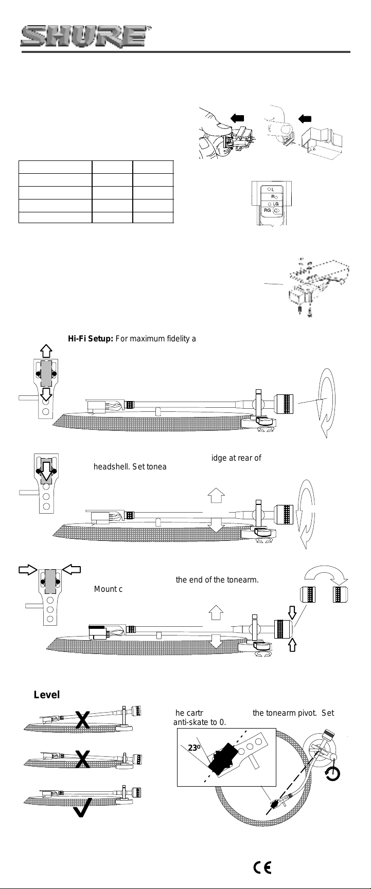
Hi-Fi Setup: For maximum fidelity and minimal record wear ,
position the cartridge using an alignment protractor or the overhang
gauge supplied with your turntable. Level your tonearm (See
Figure 7). Use Table 2 and “Setting a Precise Tracking Force”,
below, to set the typical tracking force for your cartridge. Set the
anti-skate control to the same number as the tracking force.
25, 35, AND 44 SERIES
PHONO CARTRIDGES
SC35C
Optional Headshell
Weight (part number
at front)
Figure 1
Figure 2
Figure 3
M44
Standard DJ Setup: Mount cartridge at rear of
headshell. Set tonearm height to 4-5. Set tracking
force to 3 grams. Set anti-skate control to 0.
Unorthodox DJ Setup: Reverse the counterweight
and mount it flush with the end of the tonearm.
Mount cartridge (with headshell weight) flush with
the front edge of the headshell. Set anti-skate
control to 0.
Level Your Tonearm:
Figure 4
3 grams
Figure 5
4 – 5
0
4 – 5
Figure 6
0
Extra Skip-Resistance for DJs: Mount
cartridge at a 23 degree angle as shown, so that
the cartridge points to the tonearm pivot. Set
anti-skate to 0.
Figure 7. Level Tonearm
Copyright 2002, Shure Incorporated
27B3116 (BK)
O
23
Figure 8.
0
Printed in U.S.A.
Page 2

Setting a Precise Tracking Force
1. After mounting the cartridge on the tonearm,
rotate the circular weight at the back of the tonearm until the needle floats evenly above the
record.
2. Hold the circular weight in place and rotate
the calibration ring to read zero. The tonearm
should still float evenly above the record.
3. Rotate the weight until the calibration ring indicates the desired tracking force.
Care and cleaning
DJs: Don’t use more tracking force than nec-
essary to prevent skipping. Excess force will
burn records, damage needles, and reduce
sound quality.
Clean the stylus with the supplied cleaning
brush. Important: brush from the back to the
front only, as shown in Figure 9.
Cartridge Replacement
M44–7 N44–7 White 9.5 mV 20 to 17,000 1.5–3 3
M44G N44G Gray 6.2 mV 20 to 19,000 .75–1.5 1.5
M35S N35S Chartreuse 5.0 mV 20 to 20,000 3–5 4
M35X N35X White 6.0 mV 20 to 20,000 1.5–3 3
SC35C SS35C Light Blue 5.0 mV 20 to 17,000 4–5 4.5
M25C N25C Red 5.0 mV 20 to 18,000 1.5–3 3
Stylus
Stylus Color Stereo Output (1
KHz at 5 cm/sec
peak recorded
velocity)
Figure 9. Clean Stylus
Frequency
Response in
Hz
Tracking
force
range
(grams)
Table 2. Cartridge Specifications
All Cartridges and Styli
Standard 1/2 Inch mount for DJ turntables
Wide diameter styli for reduced record wear
Optimum Load 47 K Ohms, M44: 400–500 pF. . . . . . . .
Inductance M44: 720 mH. . . . . . . . . . . . . . . . . . . . . . . . . .
Channel Separation 20 dB at 1KHz. . . . . . . . . . . . . . . . .
Certification
Conforms to European Union Directives, eligible to bear
CE marking; meets European Union EMC Immunity requirements: EN 50 082-1, 1992.
Patent Notice
Manufactured under one or more of the following U.S. Patents: 4,275,888; 4,441,177; 4,489,442.
M35, M25C, SC35C: 200–300 pF
M35, SC35C: 425 mH
M25C: 600 mH
LIMITED TWO-YEAR WARRANTY
Shure Incorporated (“Shure”), 5800 West Touhy Ave,
Niles Illinois 60714-4608, warrants to the owner of this product that it will be free, in normal us e, of any defects in workmanship and materials for a period of two years from date of
purchase. You should retain proof of date of purchase. Shure
is not liable for any incidental, special or consequential damages. If this Shure product has any defects as described during the warranty period, cal l 1-800-516-2525 in the United
States for details on repair. Outside the United States, return
the product to your dealer or A uthorized Service Center for r epair. The p roduct w ill be r epaired, r eplaced, or exchanged and
returned to you promptly.
This warranty does not cover stylus wear, abuse or misuse of the product, use contrary to Shure’s instructi on, ordinary wear and tear, an act of God or unauthorized repair.
Some States do not a llow the e xclusion or limitation of i ncidental or consequential damages, so the above limitation or
exclusion may not apply to you. This warranty gives you specific legal rights, and you may also have other rights, whic h
vary from state to state.
Typical
Tracking
Force
(grams)
Las cápsulas Shure pueden utilizarse con equipos de lo-
Instalación de la cápsula
cutor o de alta fidelidad. Nota: La M25C no se recomienda
para “rasguñado” intensivo.
1. Quite cuidadosamente la aguja de la cápsula. Vea l a
Figura 1.
2. Use alicates de punta para conectar los alambres del
cabezal del brazo con las clavi j as de la cápsula, conforme
a la Tabla 1. Vea la Figura 2.
3. Acople la cápsula al cabez al con los tornillos que se
suministran. Vea la Figura 3. Apriete los tornillos tras colo-
car la cápsula (y el peso del cabezal, si lo desea) aplican-
do uno de los métodos que se indic an a continuación.
4. Introduzca la aguj a en la cápsula.
Elección de un método para colocar la cápsula
Configuración para a l ta fidelidad (Figura 4): Para
lograr la máxima fidelidad con el mínimo desgaste del
disco, coloque la cápsula con un transportador de al ineación o un medidor de proyección que se suministra
con el tocadiscos. Nivele el brazo (vea la Figura 7).
Consulte la Tabla 2 y el apartado “Ajuste de la fuerza
de seguimiento precis a”, que figura más adelante, para
ajustar la fuerza de seguimiento normal correspondien te a la cápsula. Ajus te el control anti pati naj e a la mi s-
ma cifra que la fuerza de seguimiento.
Configuración estándar para locutores (Figura 5):
Coloque la cápsula en la parte pos terior del cabezal.
Ajuste la altura del brazo a 4-5. Ajuste la fuerza de
seguimiento a 3 gramos. Ajus te el control antipatinaje
a 0.
Configuración no ortodoxa para locutores (Figura
6): Invierta el contrapeso y colóquelo a ras con el ex-
tremo del brazo. Coloque la cápsula (con el pes o del
cabezal) a ras con el borde delantero del cabezal.
Ajuste el control antipatinaje a 0.
Nivele el brazo: Vea la Figura 7
Ajuste de una fuerza de seguimiento precisa
1. Tras colocar la cápsula en el brazo, gi re el peso circular
situado en la parte posterior del brazo hasta que la aguja
flote uniformemente por encima del disco.
2. Sujete en su sitio el peso circular y gire el anillo graduador hasta que indique el valor cero. El brazo deberá seguir
flotando uniformemente por encima del dis co.
3. Gire el peso hasta que el anillo graduador indique la
fuerza de seguimi ento deseada.
Resistencia adicional al patinaje para locutores
Coloque la cápsula a un ángulo de 23 grados, como se
indica, de modo que la cápsula apunte al pivote del brazo.
Ajuste el control antipatinaje a 0. Vea la Figura 8.
Cuidado y limpieza
1. Locutores: No emplee una fuerza de seguimiento superior a la necesaria para evitar el pati naj e. Una fuerza ex cesiva quema los discos, daña las agujas y reduce la calidad
del sonido.
2. Limpie la aguja con el cepillo que se suministra. Importante: Cepille únicamente de atrás hacia adelante. Vea la
Figura 9.
Certificaciones
Cumple las directrices de European Union, califica para
llevar las marcas CE; cumple los requisitos de inmunidad
y compatibilidad electromagnética de European Union:
EN 50 082-1, 1992.
Declaración de patente
Fabricado bajo los términos de una o más de las patentes
siguientes en los EE.UU.: 4,275,888; 4,441,177;
4,489,442.
GARANTIA LIMITADA DE DOS AÑOS
Shure Incorporated (”Shure”), 5800 West Touhy Ave,
Niles Illinois 60714–4608, EE.UU., garantiza al propietario de
este producto que el mismo estará libre de defectos de fabricación y materiales cuando se utiliza de m o do normal por u n
plazo de dos años a partir de la fecha de compra. Conserve
el comprobante de compra. Shure no se hac e responsable
por daños incidentales, especiales ni consecuentes . Si este
producto Shure exhibe defectos como los desc ritos durante
el período de garantía, llame al teléfono 1–800–516–2525 en
los Estados Unidos para más i nf or ma ción en cuanto al pr oce-
dimiento de reparación. Fuera de los EE.UU., devuelva el
producto al distribuidor más cercano o al centro de servic i o
autorizado de productos Shure para que sea reparado. La
unidad se reparará, sustituirá o intercambiará y se le devol-
verá oportunamente.
Esta garantía no cubre des gaste de la aguj a, abus o o
uso indebido del producto, uso contrario a las ins trucciones
dadas por Shure, desgaste normal, actos de fuerza mayor o
reparaciones por entidades no autorizadas para ello.
Algunos Estados no permiten la excl usión ni limitaci ón
de daños incidentales o consecuentes, por lo cual la limitación o exclusión anterior puede no ser aplicable en su caso.
Esta garantía le otorga derechos legal es espec íficos; también se puede contar con otros derechos adicionales que
varían entre un estado y otro.
2
Page 3

Shure–Tonabnehmer können für DJ– oder Hi-Fi–Anwen-
Installation des Tonabnehmers
dungen verwendet werden. Hinweis: Der M25C wird nicht
für starkes „Scratching“ empfohlen.
1. Die Abtastnadel vorsichtig aus dem Tonabnehmer entfernen. Si ehe Abbildung 1.
2. Mit einer Nadelz ange wie in Tabelle 1 angeführt die
Drähte vom Tonarmkopf an den Stiften auf dem Tonabnehmer anschließen. Siehe Abbi ldung 2.
3. Den Tonabnehmer mit den mitgelieferten Schrauben am
Tonarmkopf befestigen. Siehe Abbildung 3. Die Schrauben nach dem Ausrichten des Tonabnehmers (und ggf.
des Tonarmkopfgewichts) anhand einer der unten beschriebenen Methoden festzi ehen.
4. Die Abtastnadel in den Tonabnehmer einführen.
Auswahl einer Methode zur Plazierung
des Tonabnehmers
Hi-Fi–Einrichtung (Abbildung 4): Für höchste Klang-
treue und minimalen Verschleiß der Schallplatte den
Tonabnehmer mit einer Überhangmeßschablone oder
einer Überhangjustierlehre (im Lieferumfang des Plattenspielers enthalten) plazieren. Den Tonarm nivellieren
(Siehe Abbildung 7). Die für den Tonabnehmer üb liche
Auflagekraft anhand von Tabelle 2 und „Einstellung
einer genauen Auflagekraft“ weiter unten einstellen.
Den Antiskating–Regler auf den gleichen Wert wie die
Auflagekraft einstel len.
Standardmäßige DJ–Einrichtung (Abbildung 5): Den
Tonabnehmer an der Rückseite des Tonarmkopfs befestigen. Die Tonarmhöhe auf 4-5 einstellen. Die Auflagekraft auf 3 g einstellen. Den Antiskating–Wert auf 0
einstellen.
Unkonventionelle DJ–Einrichtung (Abbildung 6):
Das Gegengewicht umdrehen und bündig mit dem
Ende des Tonarms anbringen. Den Tonabnehmer (mit
dem Tonarmkopf) bündig mit der Vorderkante des To-
narmkopfs anbringen. Den Antisk ati ng–Wert auf 0
einstellen.
Nivellierung des Tonarms:
Siehe Abbildung 7.
Einstellung einer genauen Auflagekraft
1. Nach der Montage des Tonabnehmers auf dem Tonarm
das runde Gewicht an der Rückseite des Tonarms solange
drehen, bis die Nadel glei chmäßig über der Schallplatte
schwebt.
2. Das runde Gewicht festhalten, und den Eichring auf Null
drehen. Der Tonarm sollte immer noch gleichmäßig über
der Schallplatte schweben.
3. Das Gewicht solange drehen, bis der Eichring die gewünschte Auflagekraft anzeigt.
Zusätzlicher Überspringwiderstand für
DJs
Den Tonabnehmer wie dargestellt in einem Wi nkel von
23 Grad montieren, damit der Tonabnehmer auf das Tonarmgelenk zeigt. Den Antiskating–Wert auf 0 ei nstellen. Siehe
Abbildung 8.
Pflege und Reinigung
1. DJs: Nicht mehr Auflagekraft verwenden als notwendig,
um ein Überspringen der Nadel zu vermeiden. Zu hohe
Auflagekraft brennt Sc hallplatten, beschädigt Nadeln und
reduziert die Tonqualität.
2. Die Abtastnadel mit der mitgelieferten Reinigungsbürste
reinigen. Wichti g: Nur von hinten nach vorne bürsten. Sie-
he Abbildung 9.
Zertifizierung
Entspricht den Richtlinien der Europäischen Union, zum
Tragen des CE–Zeichens berechtigt; erfüllt die Anforderungen der Europäischen Union für elektromagnetische
Verträglichkeit: EN 50 082-1, 1992.
Patenterklärung
Unter einem oder mehr der folgenden US–Patente her-
gestellt: 4,275,888; 4,441,177; 4,489,442.
EINGESCHRÄNKTE ZWEIJÄHRIGE GEWÄHRLEISTUNG
Shure Incorporated (”Shure”), 5800 West Touhy Ave,
Niles, Illinois 60714–4608, USA garantiert dem Besitzer
dieses Produkts für zwei Jahre ab Kaufdatum, das s es bei
sachgemäßem Gebrauch frei von Material– und Herstellungsfehlern ist. Ein Beleg des Kaufdatums sollte aufbewahrt
werden. Shure haftet nicht für zufällige, besondere oder Folgeschäden. Wenn d ieses Shure Produkt währ end d er Garantiefrist einen der beschriebenen Mängel aufweist, ist die Garantieabteilung in den USA unter der Nummer
1–800–516–2525 zu verständigen, um Detailinf o r m at ionen
über die Reparatur zu erhalten. Außerhalb der Vereinigten
Staaten ist das Produkt zur Reparatur an Ihren Händler oder
die zuständige Vertragskundendienstzentrale zu senden.
Das Produkt wird repariert, umgetauscht oder ersetzt und Ihnen umgehend zurückgesendet.
Diese Garantie gilt nicht für die Abnutzung der Abtastnadel sowie bei uns ac hgemäßer Verwendung oder Zweckentfremdung des Produkts, einem von der Shure Bedienungsanleitung abweichenden Gebrauch, normalem Verschleiß,
Schäden durch höhere Gewalt oder nicht autorisierter Reparatur.
Einige Staaten gestatten den Ausschluss bzw. die
Einschränkung der zufälligen oder Folgeschäden nic ht, so
dass obige Einschränkungen möglicherweise auf Sie nicht
zutreffen. Diese Garantie verleiht Ihnen bestimmte Rechtsmittel; außerdem haben Sie je nach örtlicher Rec htslage
eventuell noch andere Rechte.
Les cellules Shure peuvent être utilisées dans les appli-
Installation de la cellule
cations DJ ou Hi-Fi. Remarque : la M25C n’est pas recommandée en cas de scratching intensif.
1. Avec précaution, retirer la pointe de lecture de la cellule.
Voir figure 1.
2. Utiliser une pince à bec fin pour brancher les fils de la
coquille du bras de lecture aux broches de la cellule conformément au tableau 1. Voir figure 2.
3. Fixer la cellule à la coquille avec les vis fournies. Voir
figure 3. Serrer les vis après avoir positionné la cellule (et
la masse de la coquille, le cas échéant) en appliquant
l’une des méthodes décrites ci–dessous.
4. Insérer la pointe de lecture dans la cellule.
Choix d’une méthode de
positionnement de la cellule
Configuration Hi-Fi (figure 4) : Pour maximiser la
fidélité et minimiser l’usure des disques, positionner la
cellule à l’aide du rapporteur d’alignement ou de la
jauge de dépassement fourni(e) avec la platine. Mettre
le bras de lecture à niveau (voir figure 7). Se reporter
au tableau 2 et à la rubrique «Réglage d’une force
d’appui précise» ci–dessous pour régler la force d’appui type de la cel l ul e. Régler l’antiskating à la même
vale ur que la force d’appui.
Configuration DJ standard (figur e 5) : Monter la ce-
llule à l’arrière de la coquille. Régler la hauteur du bras
de lecture à 4-5 et la force d’appui à 3 grammes. Ré-
gler l’antiskating à 0.
Configuration DJ spéciale (figure 6) : Retourner le
contrepoids et le monter à ras de l’extrémité du bras
de lecture. Monter la cel lul e (et la mas se de la coquille) à ras du bord avant de la coquille. Régler l’antis-
kating à 0.
Mise à niveau du bras de lecture :
Voir figure 7.
Réglage d ’une force d’appui précise
1. Après avoir monté la cel lul e sur le bras de lec ture, faire
tourner la masse circulaire qui se trouve à l’arrière de celui–ci jusqu’à ce que la pointe de lecture fl otte uniformément au–dessus du disque.
2. Maintenir la masse circul ai re en place et tourner l’an-
neau d’étalonnage jusqu’à ce qu’il indique zéro. Le bras de
lecture doit continuer à flotter uniformément au–dessus du
disque.
3. Tourner la masse jusqu’à ce que l’anneau d’étalonnage
indique la force d’appui désirée.
Résistance accrue au saut pour applications DJ
Monter la cellule à un angle de 23 degrés comme illustré
de façon à ce qu’elle soit orientée vers le pivot du bras de
lecture. Régler l’antiskating à 0. Voir figure 8.
Entretien et nettoyage
1. Applications DJ : Ne pas utiliser une force d’appui supé-
rieure à celle qui est nécessaire pour éviter à la cellule de
sauter. Une force excessive brûle les dis ques, endommage
les pointes de lec ture et diminue la qualité sonore.
2. Nettoyer la pointe de lecture avec la brosse fournie.
Important : brosser d’arrière en avant uniquement. Voir
figure 9.
Homologation
Conforme aux directives de l’Union européenne, autorisé
à porter la marque CE ; conforme aux spécifications d’im-
munité CEM de l’Union européenne : EN 50 082-1, 1992.
Avis de brevet
Fabriqué sous un ou plusieurs des brevets U.S. suivants
: 4,275,888; 4,441,177; 4,489,442.
GARANTIE LIMITÉE DE DEUX ANS
Shure Incorporated («Shure»), 5800 West Touhy Ave,
Niles Illinois 60714–4608, États–Unis, garantit au p r opriétaire
de ce produit que, pour un usage normal, ce produit est exempt de défauts de matériaux et de fabrication pour une période de deux ans, à compter de la date d’achat. Conserver
la factur e o u le re çu or iginal. Shur e n ’est pas responsable des
dommages fortuits. Si ce produit s’avère défectueux en raison d’un défaut de matière ou de fabrication, appeler le
1–800–516–2525 (si vous vous trouvez aux États–Unis) pour
obtenir les renseignements nécessaire a f in d ’é ffectuer les réparations.
À l’extér ieur des États–Unis, renvoyer le produit au distri-
buteur ou au Centre de réparations agréé. Le produit sera ré-
paré, remplacé ou échangé et sera retourné au plus tôt. Cette
garantie n’est pas applicable pour les cas d’use nor male, d’u-
sure de la tête de lecture, d’utilisation abusive ou incorrecte
du produit, d’utilisa t ion contrair e aux instru ct io n s de Shure, de
catastrophe naturelle ou de réparation non autorisée.
Certains États n’acceptent pas l’exclusion ou la limitation
des dommages fortuits ou conséquents et par suite, il est
possible que l’exclusion ou la limitation ci–dessus ne soit pa s
applicable. La présente garantie vous donne des droits lé-
gaux spécifiques et vous pouvez également avoir d’autres
droits qui varient d’un État à l’autre.
3
Page 4

5800 West Touhy Ave, Niles, Illinois 60714-
 Loading...