

Page 1
SPECIFICATIONS
Sensitivity:
-
'1,
for 10 centimeters per second.
Output at 1000 cycles - 14 millivolts
t
Response Frequency Characteristic:
c.p.s. + 2db (See Fig.
response down to 10 cycles and up to 30,000 cycles
per second.
STYLUS
Needle tip material Diamond
Needle tip radius
Needle tip
Needle tip mass
Tracking force
Recommended Load Impedance:
values of load impedance will produce a slight increase
in high frequency response. See Fig.
Inductance
D.
MI
compliance
C.
Resistance
Dimensions
CARTRIDGE
...
.....
.................
..........
....................
.....................
C).
.....................
.0.7 mil (0.01 8 mm.
.9.0 x 10-"entimeters per dyne
.1 to 2 grams - adjustable
From 20 to 20,000
There is considerable
)
-+
0.1 mil
.1.25 milligram
10,000 ohms. Higher
C.
.I30 millihenries
.I80 ohms
Overall length
Stylus to center of base
Base diameter
Range of height of
adjustment
Arm pivot to turntable
center
Weight
Weight
Packaged Weight
Replacement Styli:
M
1 Cartridge
Shure
M2
Cartridge
Shure N2 Stylus 2.7 mil radius (0.07 mm.)
..........
..........
...........
...............
M16
.............
MI2
.............
-
N1
-
.
.
50.8 50.8
41.3 41.3
.11.1 ounces (315 g.)
.10.6 ounces (300 g.)
.....
.1 pound, 3 ounces (538 g.)
Stylus .7 mil radius (0.018 mm.)
222
UARTREY AVE EVANSTON ILL . CABLE SHUREMICRO
Page 2
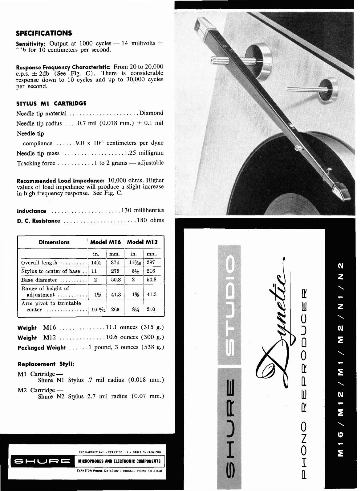
General:
Model MI6 Studio Dynetic Reproducer is of the highest
quality, employing a new electromagnetic transducer for
playing lateral phonograph records. It is intended to repro-
LP
duce
Recordings with needle forces of 1 to 2 grams with
practical elimination of record and needle wear. The Model
M16 Studio
Dynetic is intended for studio and professional
use and is capable of reproducing records up to 16" (40
cm.) in diameter. The M12 Studio
Dynetic is similar to
the Model M16, but is intended for use with equipment
where space is limited. It is designed to reproduce records
up to 12" (30 cm.) in diameter.
The cartridges in the Studio
Dynetic reproducers are of
the plug-in type and can be readily removed and replaced.
The standard cartridge furnished with the Studio Dynetic
reproducers is Model M1 which has a replaceable .7 mil
(0.018 mm.) radius stylus bearing the Model Number
N1.
For 78 rpm records and for broadcast use, the M2 cartridge is available which has a replaceable 2.7 mil (0.07
mm.) stylus which bears the Model Number N2. The M2
%
cartridge is
gram heavier than the M1 cartridge and it
allows the playing of 78 rpm records with a needle load of
3
grams.
2 to
The needle load in the Studio
Dynetic reproducers is
readily adjustable by turning a counter-balance (See Fig.
A)
visible from underneath the arm.
With a high grade
turntable and motorboard free of vibrations, the counterbalance may be adjusted as far from cartridge as possible
resulting in a 1 gram needle load. Under unsatisfactory
conditions of motorboard vibration or when playing
records with extremely high modulation, the counterbalance may be set all the way towards the cartridge,
resulting in a 2 gram needle load. Even with this adjustment, the needle load will be less than one half that which
is normally found in conventional high fidelity reproducers,
with consequent substantial improvement in record and
needle life. The Studio
Dynetic reproducer is available
with diamond styli only. To prevent damage, the diamond
stylus is packaged in a separate plastic container and should
only be installed after mounting the arm.
A
magnetic type arm rest designed to harmonize with the
appearance of the Studio
Dynetic reproducer, is furnished
in the package.
5.
The arm is brought into position to play a record by
means of a stylus control button (See Fig. A). The cartridge is lifted by pressing the control button. With the
finger pressed down on the button, the arm may be
brought into any desired position on the record. When
thp
button is released, the stylus contacts the grooves gc
with a force of I to 2 grams (depending on counter-balai,,
adjustment). In the normal operation of the arm, the
cartridge never needs to be touched. By using the control
button, it is next to impossible to damage the record or
the needle.
6.
The Studio Dynetic reproducer is fully balanced around
the vertical axis and this provides maximum stability to the
reproducer. The need for leveling of the motorboard is
entirely eliminated.
7.
A newly developed dynamic damping system is em-
ployed in the Studio
Dynetic reproducer. The counterbalance is floated on a suspension bar imbedded in special
elastomer damping material (See Fig. A). Any tendency of
the arm to resonate is damped by this member, helping to
keep rumble and "boom" to a minimum.
8.
The extremely low needle force of the Studio Dynetic
reproducer permits the use of a
MI
in the
cartridge, instead of the conventional I mil
.7
(0.018 mm.) tip needle
(0.025 mm.) tip needle. The smaller radius improves tracking on heavily modulated passages and on the inside grooves
of a record, providing an improvement in fidelity.
Application:
The Models M12 and M16 reproducers are recommended
for the highest quality applications where a lateral reproducer is required, such as playing back master records,
broadcasting, highest fidelity home systems, etc.
The M12 and
MI6 reproducers have adequate output
'
operate all modern preamplifiers. Because of the relath
low impedance of these reproducers, they may be used
16
installations which require up to 20 ft. (6.1 m.) or so of
cable between the pickup and the preamplifier. The total
cable capacity should not exceed 1500 micro-microfarad.
Features:
The Studio Dynetic reproducers embody exclusive improvements which represent a break-through in the art of
phonograph reproduction.
1.
The Dynetic Principle employs a moving magnet transducer which provides extreme linearity and freedom from
distortion. The stylus assembly is readily removable and
can be replaced by the
2.
Since the magnet turns on its vertical axis, it is possible
user.
to place the diamond tip at the end of a light magnesium
beam providing
a
needle tip mass of
1%
milligrams. The
stylus assembly is held in a durable elastomer composition
7
which provides a needle compliance of
x cm. per
dyne. Vertical compliance at the needle tip is excellent.
Because of these factors, needle talk is practically nonexistent.
3.
The tone arm is made of light high-strength aluminum
in the form of a column tapering toward the front and
reinforced at midpoint for greater strength. Because of this
construction, the arm is devoid of resonance. A new
groove-oriented stylus assembly provides the correct offset
angle for proper tracking.
4.
All of the load bearing pivots are jewelled. The cartridge is mounted on a balance beam which has a cross
shaft pivoting in a sleeve-and-cap ruby bearing at either
end. The main arm bearing is a convex ruby thrust bearing.
These bearings are extremely sturdy, durable, and provide
an almost frictionless pivot designed to provide a lifetime
of trouble-free service.
Installation:
The M12 or MI6 reproducer may be mounted on any
convenient place on the motorboard. For optimum tracking
angle reduction, the M16 reproducer is mounted with the
needle tip passing
of the turntable.
needle tip passing
lY'z"
(10.3 mm.) beyond the center pin
,The M12 reproducer is mounted with the
?A"
(6.4 mm.) beyond the center of the
turntable.
A
template is included with the reproducer to facilitate
correct installation of the reproducer and the arm rest with
respect to the turntable.
When properly mounted the Studio
Dynetic reproducers
are less subject to the effects of floor vibration than conventional high-fidelity pickups and they will not be unduly
affected by walking, dancing, etc. in the vicinity of the
reproducer. To achieve this type of performance, both the
reproducer and the turntable should be rigidly attached to
the motorboard. In this manner any vibration reaching the
motorboard will act equally upon the turntable and the
reproducer, thus cancelling the effect of vibration. It is
recommended that the motorboard itself be at least
%"
(19.1 mm.) thick and be mounted on a sponge rubber strip
to minimize the possibility of beng set into
motion
by
vibrations.
The following steps are recommended in installing
Studio
Dynetic reproducer (See Fig.
1.
Remove the cartridge by gently pulling it lengthwise
A)
:
away from the arm. This is to avoid the possibility of
damage during installation.
Page 3

2.
Using the template, drill three starting holes for the
mounting screws which fasten the base against the
motorboard (if the motorboard is made of metal, drill three
through holes of suitable size).
3.
Drill through hole for the leads, as indicated on the
template.
4.
Fasten stand-off terminal strip at any convenient place
underneath the motorboard, near the location of the arm
base.
5.
Fasten the base in place securely using the three larger
wood screws furnished. (For mounting to metal turntable
base, using the three larger machine screws furnished.) Slip
over the arm pivot post the black ornamental disc so that
'+
is seated in the larger recess at the top of the base, with a
Jot aligned with lead hole in the base.
6.
Slip the template on the base and pivot it to any convenient place on the motorboard. Locate and drill the
holes for the arm rest and fasten arm rest in place with the
three small wood screws furnished. (For mounting to
metal turntable base, use the three smaller machine screws
furnished.) Slip the black ornamental disc on the arm rest.
CAUTION:
Screws should not protrude through and in-
terfere with the functioning of the turntable mechanism.
7.
Slide the arm on the post and tighten height adjustment
screw gently so that the bottom edge of the front of the
arm is approximately
9/32" (7.1
mm) from the surface
upon which record rests. (Caution: The cartridge should
be removed from the arm during this adjustment). The
height adjustment screw should be tightened only
suficiently to hold the arm firmly in place Excessive tightening will deform the vertical bearing and prevent free
motion of the arm.
WIELD
TO
STUDIO
DYNETIC
REPRODUCER
FIGURE A
The circuit diagram of recommended connections for single
channel reproduction of monophonic or stereophonic discs
is
shown in Fig. B.
NOTE: The Models
MI2 and MI6 Studio Dynetic Reproducer as now supplied is equipped with the proper cartridge
socket and the proper wiring to be used with the Shure
M21 Studio STEREO Cartridge for stereophonic disc
reproduction.
Connections for the Model M21 Studio STEREO Cartridge
should be made as indicated on the Studio
STERFiO Dynetic
Cartridge Reproducer Data Sheet.
8.
Thread the pickup lead through the slot in tJ,e black
disc and through the hole in the base and connect to the
terminal strip. Make sure the leads are sufficiently slack
to permit the arm to move freely. The red lead from the
01
pickup should be connected to terminal I
strip; the black lead should be connected
white lead should be connected to
term~r.ar
the terminal
tc
terminal
4;
the shield
from the pickup should be connected to terminal
A
single conductor shielded cable may be used to connect
the Studio
Dynetic Reproducer to the preamplifier input.
The conductor should be connected to terminal
terminal strip; the shield should be connected to terminal 7;
a "jumper" lead should be connected between terminals
and
5;
should be connected between terminal
an ordinary piece of hook-up wire or "bell" wire
6
and the preamplifier
chassis.
The Studio
Dynetic Reproducer is intended for operation
Into a resistance of 6,700 to 10,000 ohms. As most preamplifiers have an impedance of 27,000 ohms or more,
10,000 ohm resistor is included in the package and it should
be connected across terminals
Install the needle in the cartridge in accordance with
9.
5 and 7 of the terminal strip.
instructions (see "stylus installation and replacement").
Handle the needle with care, but be sure that needle is
firmly seated in socket. Use gentle and sufficient pressure
to accomplish this. A poorly set needle will affect tracking
and cause distortion.
3.
8
2;
the
of the
8
a
1\11
10.
Replace the cartridge in the arm socket. Check height
of arm by gently and carefully swinging the arm over the
TERMINAL STRIP
turntable pad. In some installations, it may be desirable
to raise or lower the arm to insure proper record contact
or turntable clearance. The tip of the stylus must clear the
pad to prevent damage to the stylus.
When mounting the MI2 Studio Dynetic Reproducer on
the Rondine
&~-$O~f~~~
AMPLIFIER
A29R Adapter Plate is an available accessory, designed to
mount on the turntable chassis, using the pre-drilled and
tapped holes in the upper right hand corner of the chassis.
(See information provided with the turntable.) The adapter
FIGURE
B
mounts with three
Rek-0-Kut B12 Series turntables, the Shure
8-32
screws.
Page 4

The MI2 reproducer can now be installed on the adapter
plate using the 8-32 screws provided with the
A29R
Adapter. (See instructions for mounting reproducer under
"Installation.")
Operation:
Place a record on the turntable, press the stylus control
button, and move the arm so that the stylus tip is over the
desired place on the record. Release the control button and
the tip will fall gently into the groove. The ornamental
name plate at the top of the cartridge has a line which
indicates the location of the stylus. In this manner, it is
very simple to find any desired selection on a record.
FREQUENCY IN CYCLES PER
FREQUENCY
LCONITAMT VELOCITY1
FIGURE
SECOND
RESPONSE
C
The records should be kept clean and free from dust and
scratches. In playing dusty records, it will be found that
dust accumulates on the tip of the stylus. This can
seriously affect tracking of any high fidelity reproducer.
The stylus tip should be cleaned periodically with a soft
camel's hair brush. This can be done without removing
the needle or cartridge from its socket.
A satisfactory means to insure constant cleaning of the
needle is to mount a small soft brush on the motorboard so
that the needle tip barely touches the brush as the arm
swings to the rest position. Several satisfactory brushes are
available and may be obtained from the same dealer who
sells this reproducer.
No special precautions are necessary beyond ordinary
care. The reproducer will operate dependably in hot or
cold climates.
The N2 stylus has a diamond tip, 2.7 mil (0.07 mm.)
radius for use in the Model
M2
Studio Dynetic cartridges.
This needle is color coded with a white dot.
Caution:
The stylus assembly, when installed in the cartridge
practically immune to damage during normal usage. However, care should be taken to avoid bending or distorting
the stylus assembly when it is installed or removed.
Stylus replacement is exceptionally simple and fast. See
Figure D.
No tools are required. To replace (Step 1)
Insert fingernail under the lip at the REAR of stylus shank.
(NOT AT THE TIP.) Start to withdraw stylus by pulling
with fingernail straight out of cartridge. (Step 2)
completely out with thumb and forefinger. (Step 3)
Grasp new stylus between thumb and forefinger and insert
into stylus socket in the cartridge with the stylus tip pointing
forward in approximate playing position. (Step
Press stylus into socket until it is firmly seated. Apply
pressure at rear portion of the shank. (NOT AT THE TIP.)
The cartridge bearings establish the proper orientation of
the needle when inserted in the above manner.
Guarantee:
W
Each Studio Dynetic reproducer is guaranteed to be free
from electrical and mechanical defects for one year from
date of shipment from factory, provided all instructions are
complied with fully. The guarantee does not cover needle
wear nor does it
cover damage to the needle from abuse or
mishandling.
Step
One
%P
Two
-
4)
-
Lift
-
-
Stylus Installation and Replacement:
Special
Note:
Because the stylus-magnet assembly plays
such an extremely important part in the overall performance of the Studio
Dynetic Phono Reproducer, be certain
that any replacement stylus is a genuine Shure "Studio
Dynetic" stylus.
N1 stylus has a diamond tip, 0.7 mil (0.02 mm.)
The
radius for use
in
the Model M1 Studio Dynetic cartridge.
This needle is color coded with an orange dot.
Copyright,
27A122
(3-66)
1957,
Shure Brothers, Inc.
Step
Thne
FIGURE
Step
D
Foul
Printed in
U.S.A.
 Loading...