

Page 1
Shure Brothers Incorporated
222 Hartrey Avenue
Evanston IL 60202-3696 U.S.A.
LX Wireless System
SERVICE MANUAL CHANGE NOTICE
LX4 DIVERSITY RECEIVER
Changes and corrections have been made to the Service Manual for the LX4 Diversity Receiver. To update
your Service Manual, remove the pages identified in the tables below and replace them with the pages at tached to t his C hange Notice. Note that t here a re n o c hanges t o p ages n ot s pecifically i dentified i n t he t ables
below.
LX4 DIVERSITY RECEIVER SERVICE MANUAL REVISION HISTORY
Release Part Number Date Code Color
Original 25A1008 QH White
Revision 1 25B1008 QL Pink
Revision 2 25C1008 SC Tan
Revision 3 25D1008 SI White
Revision 4 25D1008 TL White
Revision 5 25D1008 BK White
Revision 5 25D1008 DL Red
CHANGES EFFECTIVE DECEMBER 21, 2004
REMOVE
these pages from the
LX4 Service Manual
Pages 26 – 28 Pages 26 – 28
E1999, Shure Incorporated Printed in U.S.A.
25–1008–1 (DL)
these pages into the
INSERT
LX4 Service Manual
Page 2
LX4 Diversity Receiver
n
Á
Á
Á
ÁÁ
Á
Á
Á
Á
Characteristics
General
The Shure Model LX4 is a single-conversion superheterodyne
diversity FM receiver operating in the 169 to 240 MHz band. It is
intended for use with compatible Shure VHF wireless transmitters.
Controls and Connectors
Service Manual
25D1008 (DL)
AUDIO
3
OUTPUTS
BAL
9 11
RF A RF B
1
8
2 4
HI Z
MIC LINE
9
10
Figure 1. Identification of Controls and Connectors
1. Diversity signal indicators
2. Rf level indicators
3. Audio level indicators
4. Squelch control
5. Audio level output control
6. Power ON indicator
SQUELCH LEVEL
5
POWER
12.5 – 18.9 VDC
8
MARCAD
DIVERSITY
POWER
6
7
ANTANT
AB
7. Power ON/OFF butto
8. Antenna connectors
9. Output connectors
10. MIC/LINE slide switch
11. Power jack
Service Note: Shure recommends that all service procedures be performed by a Factory-
E1999, Shure, Inc.
Printed in U.S.A.
Authorized Service Center or that the product be returned directly to Shure Brothers Inc.
Licensing: Operation may require a user license. Frequency or power-output modifications may violate
this product’s approvals. Contact your country’s communications authorities.
Characteristics125D1008 (DL)
Page 3
Shure LX4 Diversity Receiver
Circuit Description
The Shure Model LX4 Diversity Receiver is a single-conversion
superheterodyne diversity FM receiver operating in the 169 – 240 MHz band. It
is intended for use with compatible Shure VHF wireless transmitters, including
the Shure LX, L, EC, SC, and T series hand-held and body-pack transmitters.
The LX4 has balanced LO-Z output (3-pin XLR-type connector), an unbalanced aux level audio output (1/4 inch monophonic phone jack), and audio output
level (volume) control for all outputs.
The LX4 has an externally-accessible squelch control for signal-to-noise muting system. The recessed potentiometer for squelch control is screwdriver-adjustable.
A one quarter wavelength whip type antenna can be mounted directly to the
receiver or to a full rack panel (Shure model WA440), and can then be cabled to
the receiver. Also, a Shure model WA404 antenna splitter can be used to provide
antenna inputs and dc power to the LX4.
Audio output is a 1/4-inch, single circuit (monophonic) phone jack.
Diversity channel selection and muting are provided by a noiseoperated squelch system. Noise signals are obtained from the additional detector outputs at pin 9 of U100 and U200. For diversity channel A,
the noise signal is adjusted by squelch level control R130 before amplification by
U1B. Active high-pass filter U1C removes audio components that could cause
false triggering. The noise is then rectified by D2 and smoothed by C18 to provide a dc voltage that varies in accordance with the amount of noise present on
the detected signal.
An identical scheme is followed for diversity channel B, where noise signals
are adjusted by squelch level control R230 before being amplified by U2B, filtered by U2C, rectified by D1, and smoothed by C17.
Two diversity peak A/B (yellow) LEDS are located on the front of the unit illuminate to indicate which diversity channel (A, B, or both) have been selected by
the receiver. When the quality of the received signal
is below the squelch threshold level, both LEDs are extinguished. Audio peak
LEDs illuminate when the deviation level of the received signal
exceeds the following deviation:
LED Color
1 – Green 1.5
2 – Green 4.0
3 – Green 7.0
4 – Amber 11.0
5 – Red 14.0
Deviation kHz
Characteristics
2
25D1008 (DL)
Page 4

Shure LX4 Diversity Receiver
Diversity Control Signals
The dc noise signals are compared by U3A, U3B, U3C, and U3D to produce
diversity control signals. These signals directly control analog switches U6A and
U6B, and diversity A/B LEDs D9 and D10. These switches control the flow of
audio signals from U1A and U2A.
Squelch Control
Squelch comparators U3A and U3C compare a dc level from the user
squelch control, R66, to the dc noise level signals coming from each diversity
channel. When the noise level in both channels exceeds a preset level, the audio output of the receiver is squelched. Comparator U4A provides additional
signal attenuation in the squelched state by shutting off compander U9B.
However, if the noise level in each channel is comparable and below the
squelch threshold, then U3B and U3D will allow both channels to be active and
both diversity indicators will be illuminated. Because the
signals from each channel are correlated, but the noise is uncorrelated,
a theoretical signal-to-noise improvement of 3 dB is possible with this arrangement.
Balanced LO-Z Output
After passing through analog switches U6A and U6B, audio signals from the
two channels are buffered by U5A before entering three-pole, low-pass filter Q1.
They then enter compander U9B, which provides 2:1 logarithmic expansion. An
additional IC amplifier U5B operates in conjunction with U9B to provide a lower
noise floor. The output of this stage is applied to volume level control R32. In
order to provide a balanced LO-Z output, U5C and U5D operate as a bridging
amplifier. HI-Z audio output connector J3 taps off U5D output.
Audio Indicators
An audio LED indicator display lets the user know when the transmitter (and
audio level) deviation is approaching the limit of 15 kHz. This function is implemented by the U11 display chip. Two rf level LED strings are provided to indicate
relative rf strength of transmitters received by each antenna. They are powered
by display chips U10 and U12, which are controlled by U100 and U200 signal
strength pins.
Characteristics325D1008 (DL)
Page 5

Shure LX4 Diversity Receiver
Independent Rf Sections
Two complete, independent rf sections are provided for diversity
reception. Signals enter the receiver via detachable, single-element quarterwave antennas. For diversity channel A, they pass through a filter that is doubletuned by L100 and L101 before entering dual gate MESFET amplifier Q100. The
output of this stage is triple tuned by L103, L104, and L105, which filter the signals before they enter gate 1 of
MESFET mixer Q101. The local oscillator (LO) signal, which is applied to gate 2
of Q101, is provided by transistor Q104. A third- or fifthovertone quartz crystal in the 50 to 70 MHz range is used to provide
frequency control. The collector circuit of the oscillator is tuned by
L113 and L114 to the third harmonic of the crystal (150 to 210 MHz)
to provide the correct injection frequency for a 10.7 MHz intermediate frequency
(IF).
The output of mixer Q101 is tuned to 10.7 MHz by L108 before being applied
to ceramic filter FL100. Transistor Q102 provides IF amplification to make up for
filter losses. Signals then pass through a second IF filter, FL101, before entering
the integrated circuit IF amplifier/detector, U100. The detected audio is taken
from pin 8 and is then amplified by operational amplifier U1A.
Rf Channel B
Diversity channel B is identical in design to channel A. Signals first pass
through a double-tuned filter consisting of L200 and L201 before entering amplifier Q200. The output of this stage is triple-tuned by L203, L204, and L205 and
fed to gate 1 of mixer Q201. LO injection is provided by buffer transistor Q103,
which is tuned by L112 and L111 to the third harmonic of the crystal frequency.
The buffer stage helps to isolate the diversity channels from one another by preventing crosstalk through the common LO section.
The output of mixer Q201 is tuned to 10.7 MHz by L208 before being applied
to ceramic filter FL200. Signals are then amplified by transistor Q202 before
passing through the second ceramic filter, FL201, before they enter the integrated circuit IF amplifier/detector U200. The detected audio is again taken from
pin 8 and is amplified in this case by U2A.
Rf Indicators
Rf LEDs indicate approximate rf signal strength for each channel:
LED
1 –95
2 –90
3 –80
4 –65
5 –60
Signal Strength, dBm (±10 dBm)
Characteristics
4
25D1008 (DL)
Page 6

Power
Shure LX4 Diversity Receiver
The Shure LX4 Diversity Receiver operates on 12.5 – 18 Vdc or from an ac
power line with 120 Vac, 60 Hz external power converter;
or 220 to 240 Vac, 50/60 Hz for export models. The dc power connector: is a
male pin coaxial jack with locking connector.
A green power LED, D11, indicates when power is being supplied to the receiver by an external power converter. The circuitry will operate normally with an
input of 12.5 to 18 Vdc. Reverse polarity protection
is provided by D8, and voltage regulation is accomplished by U7. The power input, HI-Z and balanced LO-Z output connectors are filtered to prevent local oscillator radiation from the cables and to protect the
receiver from the effects of external electromagnetic fields.
Characteristics525D1008 (DL)
Page 7

Shure LX4 Diversity Receiver
Notes:
Notes:
6
25D1008 (DL)
Page 8
Shure LX4 Diversity Receiver
Test Component Locations
Test Component Locations725D1008 (DL)
Page 9

Shure LX4 Diversity Receiver
Preliminary Tests
Listening Test
Before completely disassembling the receiver, operate it to determine whether it is
functioning normally and try duplicating the reported malfunction. Refer to the User
Guide for operating instructions, troubleshooting suggestions, and specifications.
Review any customer complaint or request, and focus the listening test on any
reported problem. The following, more extensive, functional tests require partial disassembly .
Functional Tests
Refer to the Disassembly section to partially disassemble the receiver for the following functional tests.
Use dc blocks at all rf output to protect test equipment.
Verify operation and reported malfunction, referring to the product User’s
Guide for a description of the unit as well as information on its
operation, troubleshooting, and technical data.
Preliminary Tests
8
25D1008 (DL)
Page 10

Rf Test
Á
Á
ÁÁ
Á
Á
Á
Shure LX4 Diversity Receiver
Receivers that pass this test do not contain any “drop-out” or “range” problems.
MARCAD
DIVERSITY
POWER
RF A RF B
AUDIO
SQUELCH LEVEL
RF SIGNAL GENERATOR
HI Z
OUTPUTS
BAL
MIC LINE
POWER
12.5 – 18.9 VDC
DC BLOCK
NOTE: DC VOLTAGES ARE PRESENT AT MOST
RF TEST POINTS. USE A DC BLOCK ON THE
RF SIGNAL GENERATOR TO PROTECT
TEST EQUIPMENT.
ANTANT
AB
LX4 Receiver Rf Signal Generator
Power: ON Frequency: Receiver frequency
Level (gain): Max Modulation: None
Squelch: Mid
Figure 2. Rf Alignment Functional Test Set-Up
For channel A:
1. Set the receiver’s squelch control to its middle position and the volume
control to its maximum position.
2. Set the rf generator to the receiver’s frequency.
3. Remove the receiver’s antenna. Plug the
BNC end of the 50 Ω test cable
into the signal generator and the other end to the
channel A antenna input.
4. Apply power to the LX4.
5. Verify that the unit unsquelches with rf signals greater than –89 dBm.
6. When the unit unsquelches, verify that the “Rf”
LED glows.
Repeat this test for channel B.
Preliminary Tests925D1008 (DL)
Page 11
Shure LX4 Diversity Receiver
ÁÁ
Á
Á
Á
Audio Tests
HI Z
RF SIGNAL GENERATOR
AUDIO ANALYZER
OUTPUTS
BAL
MIC LINE
POWER
12.5 – 18.9 VDC
ANTANT
AB
DC BLOCK
NOTE: DC VOLTAGES ARE PRESENT AT MOST
RF TEST POINTS. USE A DC BLOCK ON THE
RF SIGNAL GENERATOR TO PROTECT
TEST EQUIPMENT.
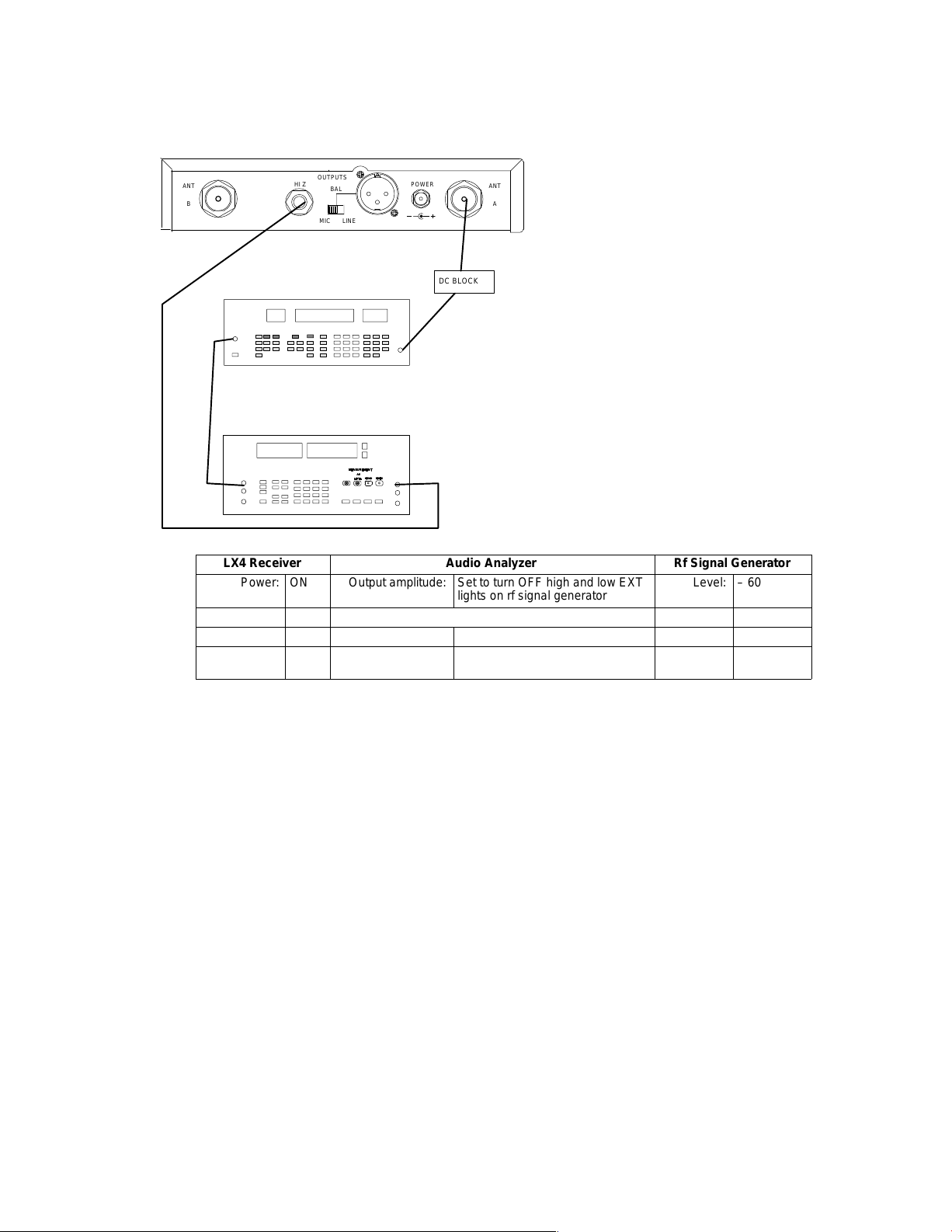
LX4 Receiver Audio Analyzer Rf Signal Generator
Power: ON Output amplitude: Set to turn OFF high and low EXT
Level: – 60 dBm
lights on rf signal generator
Level (gain): Max Filters: Deviation: 15 kHz
Squelch: Mid 400 Hz High-Pass: ON Modulation: EXT 1 kHz
30 kHz Low-Pass: ON Frequency: receiver
frequency
Figure 3. Audio Test Set-Up, steps 1 – 5
Note: The amplitude may have to be adjusted so that neither the HI EXT nor the LO
EXT LEDs on the rf signal generator are on. This amplitude should be between 1.4
and 1.5 V rms.
1. Set the rf signal generator level to –60 dBm, its deviation to
15 kHz, and its external modulation to 1 kHz.
2. Adjust the audio analyzer’s output amplitude so that the high and low
EXT lights on the rf signal generator are off.
3. Using a 3.3 kΩ load, connect the receiver’s unbalanced audio output to
the audio analyzer. The receiver’s volume control should still be in its
maximum position.
4. Engage the 400 Hz high-pass filter and the 30 kHz low-pass filter on the
audio analyzer.
5. Verify the following receiver measurements:
S Audio level is 400 mVrms, "90 mV. Record the
measurement as a reference level for the following steps.
S total harmonic distortion (THD) is <0.75%.
Preliminary Tests
10
25D1008 (DL)
Page 12

Shure LX4 Diversity Receiver
ÁÁ
Á
Á
Á
HI Z
RF SIGNAL GENERATOR
AUDIO ANALYZER
OUTPUTS
BAL
MIC LINE
POWER
12.5 – 18.9 VDC
ANTANT
AB
DC BLOCK
NOTE: DC VOLTAGES ARE PRESENT AT MOST
RF TEST POINTS. USE A DC BLOCK ON THE
RF SIGNAL GENERATOR TO PROTECT
TEST EQUIPMENT.
LX4 Receiver Audio Analyzer Rf Signal Generator
Power: ON Output amplitude: Set to turn OFF high and low EXT
Level: – 60 dBm
lights on rf signal generator
Gain: Max Filters: Deviation: 15 kHz
Squelch: Mid 400 Hz High-Pass: OFF Modulation: EXT 1 kHz
30 kHz Low-Pass: ON Frequency: Receiver
frequency
Figure 4. Audio Functional Test Set-Up, steps 6 – 14
6. Use external modulation only on the rf signal generator. Input a 100 Hz
signal from the audio analyzer to the external modulation input of the rf
signal generator.
7. Disengage the 400 Hz high–pass filter on the audio analyzer.
8. Verify that the receiver’s unbalanced audio output is within +2 dB, –1 dB
of the reference level recorded in step 5.
9. Change the audio analyzer’s frequency to 10 kHz.
10. Verify that the receiver’s unbalanced audio output is –7.5 dB to –10.5 dB
from the reference level recorded in step 5.
11. Place a 150 Ω load across the receiver’s balanced output. Verify that it is
in the MIC position.
12. Connect this output to the audio analyzer and select the float position.
Verify that the output is 65 mVrms, "15 mV.
13. Remove the 150 Ω load.
14. Take the audio analyzer input out of the float position.
Repeat this test for channel B.
After all testing has been completed, remove the test cable and reinstall the antenna. If the receiver passes these tests, the unit is functioning correctly and
does not require alignment.
Preliminary Tests1125D1008 (DL)
Page 13

Shure LX4 Diversity Receiver
Disassembly and Assembly
! IMPORTANT SAFETY INSTRUCTIONS !
1. READ these instructions.
2. KEEP these instructions.
3. HEED all warnings.
4. FOLLOW all instructions.
5. DO NOT use this apparatus near water.
6. CLEAN ONLY with a damp cloth.
7. DO NOT block any of the ventilation openings.
Install in accordance with the manufacturer’s
instructions.
8. DO NOT defeat the safety purpose of the grounding-type plug. The third prong is provided for
your safety . When the provided plug does not fit
into your outlet, consult an electrician for
replacement of the obsolete outlet.
9. PROTECT the power cord from being walked on
or pinched, particularly at plugs, convenience
receptacles, and the point of exit from the
apparatus.
10. USE only attachments/accessories specified by
the manufacturer.
11. USE only with a cart, stand, tripod, bracket, or
table specified by the manufacturer or sold with
the apparatus. When a cart is used, use caution
when moving the cart-apparatus combination to
avoid injury from tip-over.
12. UNPLUG this apparatus during lightning storms
or when unused for long periods of time.
13. REFER all servicing to qualified service personnel. Servicing is required when the apparatus
has been damaged in any way, such as when the
power-supply cord or plug has been damaged,
liquid has been spilled or objects have fallen into
the apparatus, the apparatus has been exposed
to rain or moisture, does not operate normally, or
has been dropped.
Voltages in this equipment are hazardous to life. No user-serviceable parts are inside.
Refer all servicing to qualified service personnel. The safety certifications of the LX4 Diversity Receiver
do not apply when the operating voltage is changed from the factory setting.
Disassembly
! CAUTION !
Observe precautions when handling this static-sensitive device.
! WARNING !
Remove the case:
1. Remove the six screws from the case top, which includes two screws on
the top and two screws on either side.
2. Slide the case off the frame from front to back.
The front panel must be removed to access the printed circuit board:
3. Remove the clip from the center front panel frame screw tabs.
4. Unlock the four snap-in tabs to detach the front panel. Begin with the
bottom two tabs, placing your fingers on the bottom of the chassis just
behind each tab and squeezing down with your thumbs on the top of the
front panel.
5. Next, release the two top tabs.
Disassembly and Assembly
12
25D1008 (DL)
Page 14

Reassembly
Shure LX4 Diversity Receiver
Remove the printed circuit board (pcb):
1. Remove the nuts and washers from the antenna input
connectors and the HI-Z audio output connector.
2. Remove the two screws on either side of the balanced
output XLR connector.
3. Unplug the dc power input from the pcb.
4. Remove the six screws anchoring the pcb to the bottom
of the chassis.
5. Lift the pcb from the front and pull forward. Note the lock
washers on the inside of the antenna connectors and HI-Z
audio output connector.
Replace the printed circuit board:
1. Carefully replace the six screws that anchor the pcb to the
bottom of the chassis and replug the dc power input to the pcb. Note the
lock washers on the inside of the antenna connectors and HI-Z audio
output connector.
2. Replace the two screws on either side of the balanced output XLR connector.
3. Replace the nuts and washers from the antenna input
connectors and the HI-Z audio output connector.
Replace the front panel:
1. Slide the case on the frame from front to back.
2. Lock the four snap-in tabs to attach the front panel.
3. Replace the six screws from the case top (two screws on the top and two
screws on each side).
4. Replace the clip from the center front panel frame screw tabs.
Disassembly and Assembly1325D1008 (DL)
Page 15

Shure LX4 Diversity Receiver
Notes:
Notes:
14
25D1008 (DL)
Page 16

Service Procedures
Test Equipment
Most test equipment needed is described in the Shure Wireless
Service Equipment Manual. The following test equipment (or approved equiva-
lent) is also needed.
Equipment Type Model
Audio analyzer *Hewlett-Packard 8903B
Digital multimeter Fluke 87
Rf signal generator Hewlett-Packard 8656B
Frequency counter Hewlett-Packard 53181A
Spectrum analyzer Hewlett-Packard 8590L
Shure LX4 Diversity Receiver
Table 1
Test Equipment
*Audio levels in dBu are marked as dBm on the HP8903B.
Changing the Frequency
System Operating Frequencies
The LX4 Diversity Receiver printed circuit board is marked with
a group letter that identifies the range of frequencies the receiver can operate
within.
The operating frequency may be changed to a different frequency within the
same group. Before changing the operating frequency, refer
to the Functional Test section and check the receiver for proper operation.
Change the frequency by changing the crystal on the rf board.
For proper operation, the crystal must be obtained from Shure and must operate
within the frequency range of the pc board. Use the following equation to determine the operating frequency:
Carrier frequency = 3 x (nominal crystal frequency in MHz) + 10.71 MHz
After the new crystal is installed, operational tests and alignment procedures
must be performed to ensure that the receiver is operating correctly. The pcb
label should also be updated to show the new frequency and letter identification
code.
Service Procedures1525D1008 (DL)
Page 17

Shure LX4 Diversity Receiver
A
A
B
B
C
C
D
D
T90__8632
E
E
F
F
G
G
J
J
L
L
Table 2 Wireless Frequency Selections
Code Frequency Printed Circuit Board Assembly
169.445
169.505
170.000
170.245
170.305
171.045
171.105
171.845
171.905
173.800
174.100
174.400
174.500
175.000
176.200
176.600
177.000
177.600
180.400
182.000
182.200
183.200
183.600
184.600
186.200
186.350
186.600
189.000
190.600
191.900
192.200
192.600
195.000
196.600
197.600
198.600
200.300
200.350
201.650
202.200
203.000
204.200
204.600
206.000
208.200
208.300
209.000
H
216.100
216.300
217.000
218.200
218.600
219.600
221.350
232.825
233.125
234.625
237.325
T90__8632
Service Procedures
16
25D1008 (DL)
Page 18

Alignment
ÁÁ
Á
Á
Á
RF SIGNAL GENERATOR
Shure LX4 Diversity Receiver
The following steps are for channel A; channel B, is in parentheses. For example, TPA7 (TPB7) means to use TPA7 for channel A and
TPB7 for channel B.
J2
TP9
OUTPUTS
HI Z
BAL
MIC LINE
POWER
12.5 – 18.9 VDC
DC BLOCK
ANTANT
AB
TPA4
TPB4
NOTE: DC VOLTAGES ARE PRESENT AT MOST RF TEST POINTS. USE A DC
BLOCK ON THE RF SIGNAL GENERATOR TO PROTECT TEST EQUIPMENT.
LX4 Receiver Rf Signal Generator
Power: ON Frequency: carrier
Gain: Max Modulation: OFF
Squelch: Mid Amplitude: –60 dBm
Figure 3. Alignment Test Setup
1. Solder a 33 kΩ resistor between TPA4 (TPB4) and ground for rf adjust-
ments. Do the same for channel B with TPB4.
2. Set the rf signal generator frequency to the same as the LX4, with no
modulation, and its amplitude at –60 dBm.
3. Connect the power supply (PS40) to 120 Vac power and to the receiver’s
dc input connector (J2). The green power on LED of the LX4 should now
be illuminated. If not, there is a circuit malfunction.
4. Connect the rf signal generator to the 50 Ω antenna input for channel A
or channel B, as appropriate.
5. Verify that 10.0 ± 0.35 Vdc is present at TP9 (U7, pin 3), using a digital
multimeter (DMM).
Preset the adjustable circuit components as follows:
6. Set volume (R32) control fully clockwise.
7. Set squelch (R66) control to midrange.
8. Turn the LX4 power OFF.
Service Procedures1725D1008 (DL)
Page 19

Shure LX4 Diversity Receiver
Á
Á
ÁÁ
Á
Á
Á
Á
Received Signal Strength Indicator (RSSI) Adjustment
SQUELCH LEVEL
HI Z
OUTPUTS
BAL
MIC LINE
AUDIO
POWER
12.5 – 18.9 VDC
DC BLOCK
RF A RF B
RF SIGNAL GENERATOR
MARCAD
DIVERSITY
POWER
L100
L101
ANTANT
AB
L103
L104
L114
L108
L105
L113
TPA4
TPB7
TPA7
NOTE: DC VOLTAGES ARE PRESENT AT MOST
RF TEST POINTS. USE A DC BLOCK ON THE
RF SIGNAL GENERATOR TO PROTECT
TEST EQUIPMENT.
LX4 Receiver Rf Signal Generator
Power: OFF Frequency: carrier
Gain: Max Modulation: off
Squelch: Mid Mod source: none
Deviation: none
Amplitude: off
L112
L208
L111
L205
TPB4
L204
L200
L201
L203
Figure 4. RSSI Test Setup
1. Verify that the LX4 power is OFF.
2. Place a jumper between TPB7 and ground to mute channel B for channel
A alignment. (Place a jumper between TPA7 and ground to mute channel A for channel B alignment.)
3. Turn the LX4 power ON.
4. Measure dc voltage at TPA4 (TPB4).
5. Adjust rf signal generator rf output so that approximately
2.0 Vdc is measured at TPA4 (TPB4).
6. If this is unattainable even with 0 dBm generator output, adjust L108
(L208) until the voltage is above 2.0 Vdc. If adjusting L108 (L208) does
not produce more that 2.0 Vdc at TPA4, return it to the preset position
and adjust L113 and L114 (L111, L112).
7. Adjust coils L100, L101, L103, L104, L105, L108, L113, and L114 (L200,
L201, L203, L204, L205, L208, L111, and L112) for maximum voltage at
TPA4 (TPB4). Use a hex-tuning wrench for all adjustments except L108
(L208), which requires a non-metallic screwdriver.
8. Reduce the rf signal generator output level as required to keep signal
voltage under 3.0 Vdc.
9. Final adjustments should be performed with an rf signal
generator output level of approximately –85 dBm.
Repeat this test for channel B.
Note: Inductance increases as the core is turned clockwise into the coil.
The maximum inductance position is approximately two turns before full
Service Procedures
18
25D1008 (DL)
Page 20

Shure LX4 Diversity Receiver
clockwise rotation, or 13 mm (1/4-inch) below the top of the can. Minimum inductance occurs when the core
is level with the top of the can.
Use care when turning the core to avoid locking it against the pcb and
causing it to break. Should this happen, the core can be repaired either
by removing the coil assembly and replacing it or by drilling out the core
and inserting a new one, after removing any broken pieces that remain.
Sometimes a broken core may be removed using a metallic Allen wrench
of the correct size.
For coils other than L108 and L208, “sharpness” of tuning
depends on the operating frequency within the frequency group. At the
upper and lower edges of the group, a distinct peak may be difficult to
observe. In this case, the core should be adjusted for maximum inductance and remain there. At frequencies near the high end of the group
(where coils are adjusted to minimum inductance), do not back cores
beyond the point where they are level with the top of the can. Only minimum change in inductance occurs beyond this point.
Service Procedures1925D1008 (DL)
Page 21

Shure LX4 Diversity Receiver
ÁÁ
Á
Á
Á
Á
Audio Level Adjustments
RF SIGNAL GENERATOR
HI Z
AUDIO ANALYZER
LX4 Receiver Audio Analyzer Rf Signal Generator
Squelch: Mid Filters: Mod source: EXT
OUTPUTS
BAL
MIC LINE
POWER
12.5 – 18.9 VDC
DC BLOCK
ANTANT
AB
TPA5
R59
TPB5
L110
R58
NOTE: DC VOLTAGES ARE PRESENT AT MOST
RF TEST POINTS. USE A DC BLOCK ON THE
RF SIGNAL GENERATOR TO PROTECT
TEST EQUIPMENT.
L210
Power: ON Output amplitude: 1.46 V rms Frequency: carrier
Gain: Max Frequency: 1 kHz Modulation: FM
400 Hz High-Pass: ON Amplitude: –60 dBm
30 kHz Low-Pass: ON Deviation: 15 kHz
Figure 5. Audio Level Adjustments Test Setup
Note: Remove the 33KΩ resistor from test point TPA4 and TPB4.
Note: The amplitude may have to be adjusted so that neither the HI EXT nor the LO EXT LEDs on the rf
signal generator are on. This amplitude should be between 1.4 and 1.5 V rms.
Note: Place a jumper between TPB7 and ground to mute channel B for channel A alignment. (Place a
jumper between TPA7 and ground to mute channel A for channel B alignment.)
1. Set the rf signal generator frequency to the same as the LX4, its modulation to FM, its modulation source to EXT, its FM deviation to 15 kHz, and
its amplitude to –60 dBm.
2. Set the audio analyzer’s audio frequency to 1 kHz and its
amplitude to 1.46 V rms.
3. Connect the output of the audio analyzer to the input of the
rf signal generator.
4. Place a probe on TPA5, U1, pin 1 (TPB5) and adjust
L110 (L210) for maximum ac voltage.
5. With the probe still on TPA5 (TPB5), adjust R59 (R58) for
0.775 V ± 50 mV rms (1 kHz tone).
Repeat this test for channel B.
Service Procedures
20
25D1008 (DL)
Page 22

Noise Squelch Level Adjustment
ÁÁ
Á
Á
Á
Shure LX4 Diversity Receiver
RF SIGNAL GENERATOR
AUDIO ANALYZER
HI Z
OUTPUTS
BAL
MIC LINE
POWER
12.5 – 18.9 VDC
DC BLOCK
ANTANT
AB
TPA6
TPB6
R130
NOTE: DC VOLTAGES ARE PRESENT AT MOST
RF TEST POINTS. USE A DC BLOCK ON THE
RF SIGNAL GENERATOR TO PROTECT
TEST EQUIPMENT.
R230
LX4 Receiver Audio Analyzer Rf Signal Generator
Power: ON Output amplitude: 1.46 V rms Frequency: carrier
Gain: Max Frequency: 50 kHz Modulation: FM
Squelch: Mid Filters: Mod source: EXT
400 Hz High-Pass: ON Amplitude: –60 dBm
30 kHz Low-Pass: OFF Deviation: 15 kHz
R60
Figure 6. Noise Squelch Level Adjustment Test Setup
Note: The amplitude may have to be adjusted so that neither the HI EXT nor the LO
EXT LEDs on the rf signal generator are on. This amplitude should be between 1.4
and 1.5 V rms.
1. Set the rf signal generator frequency to the same as the LX4, its modulation to FM, its modulation source to EXT, its FM deviation to 15 kHz, and
its amplitude to –60 dBm.
2. Set the audio analyzer’s audio frequency to 50 kHz and its
amplitude to 1.46 V rms. Disengage 30 kHz lowpass filter.
3. Connect the output of the audio analyzer to the input of the
rf signal generator’s modulation input.
4. For channel A, adjust R130 for 2.0 ± 0.05 Vdc at TPA6 (positive end of
C18). For channel B, adjust R230 to 2.0 ± .05 Vdc at TPB6 (positive end
of C17).
5. Set the rf signal generator for 1 kHz modulation, amplitude to –50 dBm,
with 15 kHz deviation. Engage 30 kHz lowpass filter.
6. Measure total harmonic distortion (THD). Adjust R60 for
minimum distortion at the unbalanced output. Distortion should be <
.75%.
7. Remove the external modulation from the rf signal generator.
Repeat this test for channel B.
Service Procedures2125D1008 (DL)
Page 23

Shure LX4 Diversity Receiver
ÁÁ
Á
Á
Á
Á
Á
Á
Squelch Adjustment Test
OUTPUTS
HI Z
RF SIGNAL GENERATOR
BAL
MIC LINE
12.5 – 18.9 VDC
LX4 Receiver Rf Signal Generator
Power: on Frequency: carrier
Level (gain): Max Modulation: FM
Squelch: Mid Mod source: EXT
POWER
DC BLOCK
ANTANT
AB
NOTE: DC VOLTAGES ARE PRESENT AT MOST
RF TEST POINTS. USE A DC BLOCK ON THE
RF SIGNAL GENERATOR TO PROTECT
TEST EQUIPMENT.
Amplitude: OFF
Deviation: 15 kHz
Figure 7. Squelch Adjustment Test Setup
1. Remove the jumper between TPB7 (TPA7) and ground.
2. Set the rf signal generator output to minimum (or OFF).
3. Increase the output level until the appropriate diversity LED is illuminated. This should occur with an rf input level between –105 and –89
dBm (nominally, –100 dBm).
Repeat this test for channel B.
Service Procedures
22
25D1008 (DL)
Page 24

Notes:
Shure LX4 Diversity Receiver
Notes:2325D1008 (DL)
Page 25

Shure LX4 Diversity Receiver
Bench Checks
Power Input
n Make sure that 10.0 ± 0.35 Vdc is present at TP9 (U7, pin 3).
n If the voltage is lower than normal (but not zero), check for approximately
15 Vdc at the input of U7 (pin 1), a reversed
electrolytic capacitor (C50), or a stage drawing excessive
current.
n If the voltage is zero, check for solder bridges or shorted foil traces (de-
fective pcb).
n If the voltage is higher than normal, or if other tests prove
negative, replace U7.
n Make sure that 5.0 ± 0.25 Vdc is present at TP8 (U9, pin 7).
Audio
n If there is no audio at the output of the receiver, make sure
that the channel is not squelched. Squelch may be defeated by rotating
R130 (R230) counter-clockwise until the wipers are grounded.
n There should be 10 Vdc at TPA7 (TPB7), and the diversity A (B) LED
should be on. If not, there is a problem in the squelch circuitry; see the
“Muting” section.
n Check pin 8 of U100 (U200) for an audio signal of approximately –15
dBV. If there is no detected audio, check L110 (L210) and the components connected to pins 9–12 of U100 (U200); also check dc voltages at
U100 (U200). Replace U100 (U200) if
no other problem is found.
n If audio is present at pin 8 of U100 (U200), but not at the output of the
receiver, trace the signal through signal amplifiers U1A (U2A) and expander U9 (05B).
n Use a 1 k series resistor at the test point when checking the
audio at TPA5 (TPB5) to avoid loading the amplifier.
n Then check volume control R36 and the components going
to audio output jacks J3, J1. If no signal is present at J1, the
balanced LO-Z microphone level output, check U5C, U5D, and associated components. Check dc voltages on any stages that are not working
properly; then look for wrong or missing components. Replace IC(s) only
if no other problems are found.
n If the audio level cannot be set correctly with R59 (R58), make sure the
other diversity channel is squelched. Only one channel should be activated during this adjustment.
n If the audio level is correct for the individual channels, but not when both
are activated, check U6.
n If the audio level is correct, but the unit exhibits high THD,
increment the rf input frequency 20 kHz above and below the operating
frequency.
n If the THD drops to an acceptable level, check the local oscillator fre-
quency. Also, check FL100, FL101, FL200, and FL201 for polarity.
Bench Checks
24
25D1008 (DL)
Page 26

Rf Problems
Muting
Shure LX4 Diversity Receiver
n If the audio circuitry works correctly but the audio LEDs fail to light when
the standard test signal is applied, or remain on when there is no modulation, check dc voltages at U11, and U4A.
n Check the audio LEDs. Replace any defective components.
n Make sure that the rf test signal is being input to the correct
diversity channel. If there is no deflection on the oscilloscope at TPA4
(TPB4) when the rf coils are adjusted, check the operation of the local
oscillator.
n Turn off the rf generator and measure the injection level at TPA3 (TPB3)
with a spectrum analyzer and FET probe. It should be approximately
–15 to –20 dBm.
n If the level is correct, check the frequency of the local oscillator signal
with the frequency counter. It should be 10.7 MHz below the operating
frequency of the receiver, with a tolerance of ± .015 MHz. For example,
to receive 169.445 MHz, the local oscillator frequency would be 158.745
MHz, ± .015 MHz.
n Crystal Y100 operates at one-third of this frequency, or 52.915 MHz. The
nominal crystal frequency, which is stamped on the part, is 3.333 kHz
lower, or 52.911667 MHz in this example.
This is because the load reactance of the oscillator is not
precisely zero.
n If any of the rf coils will not tune properly, see if the associated frequency-
dependent capacitor(s) are missing or of the wrong value. If the IF coil
will not tune, check C130 (C230).
n If all of the coils tune, but the rf signal level is low, check dc
voltages and components at rf amplifier Q100 (Q200).
n If everything is working correctly, the dc voltage at TPA4 (TPB4) will be
between 1.0 and 2.0 Vdc with a –95 dBm rf input signal, depending on
component parameters and receiver frequency.
n With TPA7 (TPB7) connected to ground, the appropriate diversity chan-
nel should be squelched and the diversity A (B) LED should be off, regardless of the presence or absence of an rf input signal in that channel.
If not, check dc voltages at U3, U1, U6, and U2. Investigate any irregularities. Replace any components that are found to be defective.
n If the squelch circuit works but has insufficient adjustment range, check
for low voltage at TPA4 (TPB4) with a –100 dBm rf input signal.
n Low rf levels at the input of U100 (U200) will cause inadequate noise at
the output of U1C (U2C). In order for the noise squelch circuits to function, the detector portions of U100 (U200) must also be functioning correctly.
n Also check the dc voltages and component values of noise amplifiers
U1B (U2B) and high-pass filters U1C (U2C), if necessary.
Bench Checks2525D1008 (DL)
Page 27

Shure LX4 Diversity Receiver
Replacement Parts and Drawings
Parts Designations
The following comments apply to the parts list and the schematic:
Resistors: All resistors are surface-mount with
ance.
Capacitors: Unless otherwise noted, non-polarized capacitors are surfacemount
tolerance, and polarized capacitors are tantalum types.
Reference
Designation
A1 Printed circuit board assem-
A2 Cable, Connector Assy, DC
A3 Front Panel/Light Pipe Assy. 90A8633
A4 Knob Assembly, (volume) 65D8249A
E1 Whip Antenna 90A8380 for 169–186MHz
E2 Mounting Bracket (short) 53A8350
E3 Mounting Bracket (long) 53A8381
E4 Link Bar 31A8138
K1 Hardware Kit 90TZ1371
MP1 Knob (power) 65B8250
MP2 Nut, Hex, .8mm (power con-
NPO dielectric types with a 100 V capacity and a 5%
Table 3
Replacement Parts
Description
bly
Jack
Screw, Sems, Head, Round
(linking units)
Screw, Machine, Head, Pan
(mount units)
Screwdriver 80A498
Washer, Panel, Nylon, Black 65A8234
Bumper, Round, Black 66A8010
Plug, Hole, Black 66B8041
nector)
Shure Part Number
90_8632K [See Table 1, p.
12, to determine the GROUP
CODE in the underlined
space. e.g. 90A
90B8688
90B8380 for 186–204MHz
90C8380 for 204–240MHz
30J622E
30F8060B
95Z8562
1
/10 W rating and 1% toler-
8632K].
Replacement Parts and Drawings
26
25D1008 (DL)
Page 28

Shure LX4 Diversity Receiver
MP3
MP4 Nut, Hex, Black, 3/8–32 (1/4”
MP5 Washer, Black (1/4” jack) 30A961B
MP6 Lockwasher, Tooth, Internal,
MP7 Washer (antenna jack) 30A8154A
MP8 Nut, Hex, 5/8–24 (antenna
MP9 Lockwasher, Tooth, Internal,
MP10 Nut, Hex, M7x.75 (volume
MP11 Washer, Aluminum (volume
MP12 Screw, Sems, Head, Round
MP13 Screw, Sems, Head, Pan,
MP14 Screw, Sems, Head, Pan,
MP15 Fastener, U Type (case top) 47A108
MP16 Connector Bracket 53A8367
MP17 Top Cover, Steel 53A8410
MP18 Chassis, Steel 53A8409
MP19 Nameplate, Rear 39A8409
Y100 Crystal 40_8003A [See Table 1, p.
Washer (power connector) 95Y8562
30A884A
jack)
30P631A
3/8 (1/4” jack)
95Z8414
jack)
30R631A
5/16 (antenna jack)
30A8049A
pot.)
30A8052
pot.)
30C622B
(PCB)
30E925D
Black (top cover)
30D8178B
Black (XLR)
12 to determine the crystal
code in the underlined
space. e.g. 40CL8003A].
Table 4
Printed Circuit Board Parts
C37,41,42,61,62
C50,135,235 Capacitor, Electrolytic, SMD,
C3,4,49,52,136,236 Capacitor, Electrolytic, SMD,
C31,33,39,53,54,57,
127,227
C17,18,30,32,46 Capacitor, Electrolytic, SMD,
D1,2,3,4,5,6 Switching Diode SOT–23,
D7,8 Rectifier, Silicon, 140VDC 184A20
Capacitor, Electrolytic, 47uF,
63V, 20%
100uF, 16V, 20%
10uF, 35V, 20%
Capacitor, Electrolytic, SMD,
4.7uF, 35V, 20%
1uF, 50V, 10%
100VDC (MMBD7000L)
Replacement Parts and Drawings2725D1008 (DL)
86BE629
151DB107MD
151BF106MC
151BF475MB
151BG105KB
184A08
Page 29

Shure LX4 Diversity Receiver
D9,10,18
D11,12,13,14,15,16,
19,20,21,22,23,24,25,
26
D17 LED, Surface Mount, Red 184A18
FL100,101,200,201 Filter, Ceramic, 10.7MHz 86A8910
J1 XLR Connector (Male) 95A8598
J2 Shroud Header, 2 Position 95A8272
J3 1/4 Inch Phone Jack 95A8104
J100,200 Antenna Connector 95X8414
L1,2,4,5,102,106,107,
109,116,202,206,207,
209,216
L100,101,104,105,112
,113,200,201,204,205
L108,208 Coil, Tunable, 4.7uH 82A8005
L110,210 Quadrature Coil, 10.7MHz 82A8004
L111,114 Coil, Tunable, MC–120, 47nH 82B8003
L115 Inductor, SMD1008, .22uH 162C06
Q1 Transistor, Low Noise, SOT–23,
Q100,101,200,201 Amp., 2 Gate, Hi Gain, LO
Q102,103,104,202 Transistor, RF, SOT–23, NPN
R32 Potentiometer, 10K (volume) 46A8032
R58,59,60,130,230 Potentiometer, Trim, SMD, 5K 146D02
R66 Potentiometer, 100K (squelch) 46B8055
S1 Switch, Slide, Right Angle,
S2 Switch, Push Button, Right
U1,2 Quad Op Amp (MC33179D) 188A49
U3,4 Comparator, Quad, Low Power,
U5 Quad Op Amp, SO–14
U6 Switch, Multiplexer, Quad,
U7 Voltage regulator (LM2940T) 86A8918
U9 Compandor, SOL–16 (SA571D) 188A01
U10,11,12 Driver, Display, Dot/Bar,
U100,200 FM Detector (LA1145M) 188A129
LED, Surface Mount, Orange 184E18
LED, Surface Mount, Green 184D18
Bead, Ferrite, SMD1206, 65
OHM
Coil, Tunable, MC–120, 45nH 82A8003
NPN (MMBT5089L)
Noise, SOT143 (NE25139)
(BF840)
DPDT (Mic/Line)
Angle, DPDT (Power)
SO–14 (LP339M)
(TLC2274CD)
SO–14, (HEF4066BTD)
PCC–20 (LM3914V)
162A03
183A38
183A12
183A14
55A8061
55B8062
188A123
188A150
188A19
188A86
Replacement Parts and Drawings
28
25D1008 (DL)
Page 30

Printed in U.S.A.
Shure LX4 Diversity Receiver
LX4 Diversity Receiver: Printed Circuit Board Top View
Page 31

Shure LX4 Diversity Receiver
LX4 Diversity Receiver: Printed Circuit Board Top View
Printed in U.S.A.
Page 32

LX4 Diversity Receiver: Printed Circuit Board Bottom ViewShure LX4 Diversity Receiver
Printed in U.S.A.
Page 33

LX4 Diversity Receiver
Audio Section Schematic Diagram
Shure LX4 Diversity Receiver
Printed in U.S.A.
Page 34

LX4 Diversity Receiver
Rf Section Schematic Diagram
Printed in U.S.A.
Shure LX4 Diversity Receiver
* Note: On boards with pcb reference designator
34A8332E, the FM detector is 188A190. On
other boards, it is 188A129.
*
*
Page 35

Shure LX4 Diversity Receiver
LX4 Diversity Receiver
Audio Section Schematic Diagram
Page 36

Shure LX4 Diversity Receiver
LX4 Diversity Receiver
Rf Section Schematic Diagram
 Loading...