

Showtec Lampy 40 1U DMX-console, Lampy 20 2U DMX-console, Lampy 20 1U DMX-console, Lampy DNGL unlock dongle Showtec Lampy handleiding

LAMPY 20 / 40
Highlite International B.V. – Vestastraat 2 – 6468 EX – Kerkrade – the Netherlands
Product code: 50733 / 50734 / 50735 / 50736
USER MANUAL
ENGLISH
V1.0

1
Showtec LAMPY Series
Product: 50733 / 50734 / 50735 / 50736
Preface
Thank you for purchasing this Showtec product.
The purpose of this user manual is to provide instructions for the correct and safe use of this product.
Keep the user manual for future reference as it is an integral part of the product. The user manual shall be
stored at an easily accessible location.
This user manual contains information concerning:
● Safety instructions
● Intended and non-intended use of the device
● Installation and operation of the device
● Maintenance procedures
● Troubleshooting
● Transport, storage and disposal of the device
Non-observance of the instructions in this user manual may result in serious injuries and damage of
property.
©2020 Showtec. All rights reserved.
No part of this document may be copied, published or otherwise reproduced without the prior written
consent of Highlite International.
Design and product specifications are subject to change without prior notice.
For the latest version of this document, please visit our website www.highlite.com or contact us at
service@highlite.com.
Highlite International and its authorized service providers are not liable for any injury, damage, direct or
indirect loss, consequential or economic loss or any other loss arising from the use of, or inability to use or
reliance on the information contained in this document.

2
Showtec LAMPY Series
Product: 50733 / 50734 / 50735 / 50736
1. Table of contents
1. Table of contents ................................................................................................................................................. 2
2. Introduction .......................................................................................................................................................... 9
2.1. Before Using the Product .................................................................................................................................. 9
2.2. Intended Use ....................................................................................................................................................... 9
2.3. Product Lifespan ................................................................................................................................................. 9
2.4. Text Conventions ................................................................................................................................................ 9
2.5. Symbols and Signal Words ..............................................................................................................................10
2.6. Symbols on the Information Label ................................................................................................................10
3. Safety .................................................................................................................................................................. 11
3.1. Warnings and Safety Instructions ..................................................................................................................11
3.2. Requirements for the User ...............................................................................................................................13
4. Description of the Device ................................................................................................................................. 14
4.1. Front View ..........................................................................................................................................................14
4.1.1. Multi-Function-Faders (MFF) ......................................................................................................................15
4.1.2. Programming Section ................................................................................................................................15
4.1.3. Playback Faders .........................................................................................................................................16
4.1.4. Master Playback Fader .............................................................................................................................16
4.1.5. Touchscreen ................................................................................................................................................17
4.2. Back View ..........................................................................................................................................................18
4.3. Product Specifications ....................................................................................................................................19
4.4. Optional Accessories .......................................................................................................................................20
4.4.1. LAMPY DNGL Features ...............................................................................................................................20
5. Installation .......................................................................................................................................................... 21
5.1. Safety Instructions for Installation ..................................................................................................................21
Installation Site Requirements ........................................................................................................................21
5.3. Connecting to Power Supply .........................................................................................................................21
5.4. Connecting Accessories .................................................................................................................................21
6. Basic Concepts.................................................................................................................................................. 22
6.1. Priority Concept ................................................................................................................................................22
6.2. Tracking ..............................................................................................................................................................22
6.2.1. Basic Idea .....................................................................................................................................................22
6.2.2. Tracking in a Nutshell .................................................................................................................................22
6.2.3. Tracking through Changes .......................................................................................................................23
6.2.4. Maintaining Tracking..................................................................................................................................23
6.3. Fixture Library Basics .........................................................................................................................................24
6.3.1. Factory Library .............................................................................................................................................24
6.3.2. User Library ...................................................................................................................................................24
6.3.3. Show Library .................................................................................................................................................24
7. The User Interface .............................................................................................................................................. 25
7.1. The Internal Touchscreen Interface ..............................................................................................................25
7.1.1. The “Top Toolbar” .......................................................................................................................................25
7.1.1.1. Programmer Buttons ..........................................................................................................................26
7.1.1.2. Window Title / Active Command....................................................................................................27
7.1.1.3. Main Navigation Buttons ..................................................................................................................28
7.1.1.4. The Content Area...............................................................................................................................29
7.1.2. The Bottom Toolbar ....................................................................................................................................30
7.2. External Screen .................................................................................................................................................31
7.2.1. External Screen Functionality without the LAMPY DNGL ....................................................................31
7.2.2. External Screen Functionality with the LAMPY DNGL ..........................................................................32
7.2.2.1. The Fixtures View .................................................................................................................................32
7.2.2.2. The Groups and Presets View ..........................................................................................................33
7.2.2.3. The Virtual Executor View .................................................................................................................33

3
Showtec LAMPY Series
Product: 50733 / 50734 / 50735 / 50736
7.2.2.4. The Cuelist View ..................................................................................................................................34
7.2.2.5. The DMX Output View .......................................................................................................................34
7.2.2.6. Solitaire Game ....................................................................................................................................35
8. Operation ........................................................................................................................................................... 36
8.1. Safety Instructions for Operation ...................................................................................................................36
8.2. Starting the Console ........................................................................................................................................36
8.3. Working with Shows ..........................................................................................................................................38
8.3.1. Creating a New Show ...............................................................................................................................38
8.3.2. Loading a Show ..........................................................................................................................................39
8.3.3. Saving the Show File...................................................................................................................................40
8.4. Adding and Patching Fixtures .......................................................................................................................41
8.4.1. The Patch Table ..........................................................................................................................................41
8.4.2. The Patch Actions Menu ...........................................................................................................................42
8.4.3. Adding Fixtures to the Show File ..............................................................................................................43
8.4.4. Deleting Fixtures from the Show file ........................................................................................................45
8.4.5. Changing the Patch of Existing Fixtures .................................................................................................45
8.4.6. Changing the Name of Existing Fixtures .................................................................................................46
8.4.7. Invert Pan or Tilt for Existing Fixtures .........................................................................................................47
8.4.8. Changing User ID for Existing Fixtures ......................................................................................................48
8.5. The Setup Menu ................................................................................................................................................49
Opening the Setup Menu in a Show ..................................................................................................................49
Opening the Setup Menu from the Welcome Screen ...................................................................................49
8.5.1. Current Show View .....................................................................................................................................50
8.5.1.1. Saving the Show File ..........................................................................................................................50
8.5.1.2. Saving the Show File under a New Name .....................................................................................51
8.5.1.3. Exporting the Show File to USB .........................................................................................................51
8.5.2. Show Settings View .....................................................................................................................................52
8.5.2.1. Playback Page Change Settings ....................................................................................................53
8.5.2.2. Master Fader Settings ........................................................................................................................54
8.5.2.3. Changing the Worklight Brightness .................................................................................................55
8.5.2.4. Changing the Brightness of the Multi-Function-Fader LED .........................................................56
8.5.2.5. Setting the Multi-Function-Fader LEDs to Mimic Fixture Color ...................................................57
8.5.2.6. Changing the Desklock PIN .............................................................................................................58
8.5.2.7. Changing the Autosave Settings ....................................................................................................59
8.5.2.8. Enabling the Open Sound Control (OSC) Input ...........................................................................60
8.5.2.9. Enabling and Configuring the Sound Input ..................................................................................61
Setting the Sound Input Level / Threshold .........................................................................................................62
8.5.2.10. Enabling the Time-Code Input ........................................................................................................63
8.5.2.11. Enabling the MIDI Input .....................................................................................................................64
Setting the MIDI Channel .....................................................................................................................................64
8.5.2.12. Enabling and Configuring the DMX Output via Art-Net or sACN .............................................65
Setting Art-Net or sACN Universe and Priority ...................................................................................................65
8.5.3. System Settings View ..................................................................................................................................66
8.5.3.1. Setting the USB Keyboard Layout ...................................................................................................67
8.5.3.2. Setting the Console’s Date and Time ............................................................................................68
8.5.3.3. Configuring the Network Settings ...................................................................................................69
Dynamic Configuration ........................................................................................................................................69
Static Configuration ..............................................................................................................................................69
8.5.3.4. Updating the Console Software ......................................................................................................70
Updating the LAMPY Using USB ...........................................................................................................................70
Updating the LAMPY Using the Online Update Functionality .......................................................................70
8.5.3.5. Release Notes of the Installed Software Version ..........................................................................70
8.5.3.6. Updating the Factory Fixture Library ..............................................................................................71
Updating the LAMPY Library Using USB ..............................................................................................................71
Updating the LAMPY Using the Online Update Functionality .......................................................................71
8.5.3.7. Calibrating the Internal Touchscreen ............................................................................................72
8.5.3.8. Calibrating the External Touchscreen ............................................................................................73

4
Showtec LAMPY Series
Product: 50733 / 50734 / 50735 / 50736
8.5.3.9. Testing the Front Panel Hardware ...................................................................................................74
8.5.3.10. System Log ...........................................................................................................................................75
8.5.4. Manage Shows View .................................................................................................................................76
8.5.4.1. Manage Shows - Actions ..................................................................................................................76
8.5.4.2. Starting a New Show .........................................................................................................................77
8.5.4.3. Deleting One or Multiple Shows ......................................................................................................77
8.5.4.4. Opening a Show ................................................................................................................................77
8.5.4.5. Importing One or More Shows from USB ........................................................................................77
8.5.4.6. Exporting One or More Shows to USB .............................................................................................77
8.5.5. Fixture Library View .....................................................................................................................................78
8.5.5.1. Selecting a Fixture Library Category ..............................................................................................78
8.5.5.2. Fixture Library Action Dialog Box .....................................................................................................79
8.5.5.3. Adding a New Fixture Type ..............................................................................................................80
Starting a Fixture from Scratch ............................................................................................................................80
Starting a Fixture Using an Existing Fixture Type as a Template .....................................................................80
8.5.5.4. Deleting a Fixture Type ......................................................................................................................81
8.5.5.5. Editing / Modifying a Fixture Type ...................................................................................................81
8.5.5.6. Transferring (Copying) a Fixture Type between Libraries ...........................................................81
8.5.5.7. Importing Fixture Types from USB .....................................................................................................82
8.5.5.8. Exporting Fixture Types to USB ..........................................................................................................83
8.5.5.9. The Library Editor ................................................................................................................................84
Channel List .............................................................................................................................................................84
Select Parameter Menu ........................................................................................................................................85
Edit Ranges Menu ..................................................................................................................................................86
General Settings .....................................................................................................................................................87
8.6. Using the Home Screen ...................................................................................................................................88
8.6.1. The Fixtures View .........................................................................................................................................89
8.6.1.1. Navigating the Fixtures View ............................................................................................................89
8.6.1.2. The Fixture Item ...................................................................................................................................91
8.6.1.3. Fixture Actions Dialog Box (Magic Wand Button) ........................................................................91
8.6.1.4. Adding Elements to the Fixtures View ............................................................................................93
Adding Labels ........................................................................................................................................................93
Adding Groups .......................................................................................................................................................93
Adding Fixtures .......................................................................................................................................................94
8.6.1.5. Selecting and De-selecting Fixtures................................................................................................94
8.6.1.6. Editing Existing Elements....................................................................................................................94
Editing Labels ..........................................................................................................................................................94
Moving Items ..........................................................................................................................................................95
Deleting Items .........................................................................................................................................................95
8.6.1.7. Arranging Existing Elements ..............................................................................................................96
Arrange Linear ........................................................................................................................................................96
Arrange Arc ............................................................................................................................................................97
Arrange Grid ...........................................................................................................................................................98
Arrange Circular ....................................................................................................................................................99
Arrange Chessboard ......................................................................................................................................... 100
8.6.2. The Groups View ...................................................................................................................................... 101
8.6.2.1. The Group Item ................................................................................................................................ 101
8.6.2.2. Recording Groups ........................................................................................................................... 102
8.6.2.3. Naming Groups ............................................................................................................................... 102
8.6.2.4. Selecting and Deselecting Groups .............................................................................................. 102
8.6.2.5. Copying Groups .............................................................................................................................. 102
8.6.2.6. Moving Groups ................................................................................................................................ 102
8.6.2.7. Editing Groups .................................................................................................................................. 103
Changing the Name .......................................................................................................................................... 103
Smart Name ......................................................................................................................................................... 103
8.6.2.8. Removing Fixtures from Groups .................................................................................................... 104
8.6.2.9. Replacing a Group ......................................................................................................................... 105
8.6.2.10. Adding Fixtures to existing Groups ............................................................................................... 106

5
Showtec LAMPY Series
Product: 50733 / 50734 / 50735 / 50736
8.6.2.11. Deleting Groups .............................................................................................................................. 106
8.6.3. The Presets View....................................................................................................................................... 107
8.6.3.1. The Preset Item................................................................................................................................. 108
8.6.3.2. The Preset Actions Dialog Box (Magic Wand) ........................................................................... 109
Generate Presets ................................................................................................................................................ 109
Direct Action ........................................................................................................................................................ 109
8.6.3.3. Recording Presets ............................................................................................................................ 110
8.6.3.4. Automatically Generating Presets ............................................................................................... 110
8.6.3.5. Naming Presets ................................................................................................................................ 110
8.6.3.6. Selecting / Deselecting Presets .................................................................................................... 110
8.6.3.7. Loading a Presets Value instead of Using it as a Reference .................................................. 110
8.6.3.8. Copying Presets ............................................................................................................................... 110
8.6.3.9. Moving Presets ................................................................................................................................. 110
8.6.3.10. Editing Presets .................................................................................................................................. 111
Changing the Name .......................................................................................................................................... 111
Setting an Icon .................................................................................................................................................... 112
Setting a Color ..................................................................................................................................................... 112
8.6.3.11. Removing Values from Presets ..................................................................................................... 113
8.6.3.12. Replacing a Preset .......................................................................................................................... 114
8.6.3.13. Adding or Changing Values in Existing Presets ......................................................................... 115
8.6.3.14. Deleting Presets ............................................................................................................................... 115
8.6.4. The Values View ....................................................................................................................................... 116
8.6.4.1. Different States of Values ............................................................................................................... 117
8.6.4.2. Emptying the Value Views „Content“ ......................................................................................... 117
8.6.4.3. Programmer Buttons ....................................................................................................................... 118
Blind Button .......................................................................................................................................................... 119
Highlight Button ................................................................................................................................................... 119
Previous Fixture Button ....................................................................................................................................... 119
Next Fixture Button .............................................................................................................................................. 119
8.6.4.4. The Value Tab - Actions Dialog Box ............................................................................................. 120
Show RAW Values ............................................................................................................................................... 120
Link Attributes ....................................................................................................................................................... 121
8.6.4.5. Setting Fixture Values ...................................................................................................................... 122
Using the Encoders ............................................................................................................................................. 122
Using the Set Value Dialog Box ........................................................................................................................ 123
8.6.4.6. Setting Color Mixing Attributes ...................................................................................................... 124
Using the Encoders ............................................................................................................................................. 124
Using the Color Picker ........................................................................................................................................ 124
Using the Color Faders ....................................................................................................................................... 125
Using the Quick Colors ....................................................................................................................................... 125
8.6.4.7. Setting Values Using the Presets ................................................................................................... 126
8.6.4.8. Loading Values from Other Sources ............................................................................................ 126
Loading all Values from Current Output ........................................................................................................ 126
Loading all Values for a Specific Attribute Group from Current Output ................................................. 126
Loading all Values without Effects from Current Output ............................................................................ 126
Loading Values of one Attribute without Effects from Current Output ................................................... 126
8.6.4.9. Fanning / Spreading Values .......................................................................................................... 126
8.6.5. The Effects View ....................................................................................................................................... 127
8.6.5.1. The Effects Tab - Actions Dialog Box ........................................................................................... 128
Add Effect ............................................................................................................................................................ 128
Delete Selected FX ............................................................................................................................................. 129
Load Effects for Selected Fixtures from Output ............................................................................................ 129
8.6.5.2. Adding Effects ................................................................................................................................. 130
Predefined Effects .............................................................................................................................................. 130
Custom Effects .................................................................................................................................................... 131
8.6.5.3. Modifying Effects ............................................................................................................................. 132
8.6.5.4. Deleting Effects ................................................................................................................................ 132
8.6.5.5. Stopping Running Effects ............................................................................................................... 133

6
Showtec LAMPY Series
Product: 50733 / 50734 / 50735 / 50736
8.6.5.6. Effect Attributes ............................................................................................................................... 134
Fixtures Column ................................................................................................................................................... 134
Parameter Column ............................................................................................................................................. 135
Mode Column ..................................................................................................................................................... 135
Relative ................................................................................................................................................................. 135
Absolute ................................................................................................................................................................ 135
Curve Column ..................................................................................................................................................... 136
Size Min Column .................................................................................................................................................. 136
Size Max Column................................................................................................................................................. 136
Speed Column .................................................................................................................................................... 136
Offset Column ..................................................................................................................................................... 137
Duty Cycle Column ............................................................................................................................................ 138
Grouping Column ............................................................................................................................................... 138
Symmetric Column ............................................................................................................................................. 138
Direction Column ................................................................................................................................................ 139
Shots Column ....................................................................................................................................................... 139
8.7. Using the Playback Faders .......................................................................................................................... 140
8.7.1. The Playback-Fader Labels ................................................................................................................... 141
8.7.2. The Cue Label Background Color ........................................................................................................ 141
8.7.3. Playback Fader Pages ........................................................................................................................... 142
8.7.4. Playback View – Direct Control Section ............................................................................................. 143
8.7.5. Playback View Columns ........................................................................................................................ 144
Sort Column ......................................................................................................................................................... 144
Cue ID Column .................................................................................................................................................... 144
Name Column ..................................................................................................................................................... 144
Trig Time Column ................................................................................................................................................. 144
Trigger Column .................................................................................................................................................... 145
Manual Go ........................................................................................................................................................... 145
Wait ....................................................................................................................................................................... 145
Follow .................................................................................................................................................................... 145
Timecode ............................................................................................................................................................. 145
In Fade Column .................................................................................................................................................. 145
In Delay Column ................................................................................................................................................. 145
Out Fade Column ............................................................................................................................................... 145
Out Delay Column .............................................................................................................................................. 145
In Snap Column ................................................................................................................................................... 145
MiB Column .......................................................................................................................................................... 145
Load Values Column ......................................................................................................................................... 146
8.7.6. Recording and Modifying Cues ........................................................................................................... 147
8.7.6.1. Recording Cues to a Playback .................................................................................................... 147
8.7.6.2. Recording a Second Cue to a Playback ................................................................................... 147
8.7.6.3. Removing Values from a Cue in a Playback............................................................................. 147
8.7.6.4. Replacing all Values in a Cue in a Playback ............................................................................ 148
8.7.6.5. Adding or Changing Values in a Cue in a Playback ............................................................... 149
8.7.6.6. Deleting a Cue in a Playback ...................................................................................................... 149
8.7.6.7. Copying a Cue in a Playback ...................................................................................................... 149
8.7.7. Copying a Playback ............................................................................................................................... 150
8.7.8. Moving a Playback ................................................................................................................................. 150
8.7.9. Adjusting the Playback Settings ........................................................................................................... 151
8.7.9.1. Customizing the Fader Function .................................................................................................. 151
Fader Function .................................................................................................................................................... 152
Fader Options ...................................................................................................................................................... 152
AutoStart ............................................................................................................................................................... 152
AutoStop ............................................................................................................................................................... 152
8.7.9.2. Customizing the Button Function ................................................................................................. 152
8.7.9.3. Setting the Playback Mode .......................................................................................................... 154
Cuelist Options .................................................................................................................................................... 155
Auto-Off other Effects ........................................................................................................................................ 155

7
Showtec LAMPY Series
Product: 50733 / 50734 / 50735 / 50736
Learn Timing ......................................................................................................................................................... 155
Chase Options ..................................................................................................................................................... 156
Chase Trigger....................................................................................................................................................... 156
Playback Direction ............................................................................................................................................. 158
Cue Crossfade .................................................................................................................................................... 158
8.7.9.4. Setting the Run Mode of the Playback....................................................................................... 159
8.7.9.5. Setting the Off Time of the Playback .......................................................................................... 160
8.8. Using the Multi-Function Faders .................................................................................................................. 161
8.8.1. Fixture Mode (Orange) ........................................................................................................................... 162
8.8.1.1. Assigning Fixtures to a Fixture MFF ................................................................................................ 162
8.8.1.2. Deleting Fixtures from the MFF Faders ......................................................................................... 162
8.8.1.3. Copying a Fixture MFF .................................................................................................................... 162
8.8.1.4. Moving a Fixture MFF ...................................................................................................................... 162
8.8.1.5. Naming a Fixture MFF ..................................................................................................................... 162
8.8.2. Group Mode (Green) ............................................................................................................................. 163
8.8.2.1. Assigning Groups to a Group MFF ............................................................................................... 163
8.8.2.2. Deleting Groups from the MFF Faders ......................................................................................... 163
8.8.2.3. Copying a Group MFF .................................................................................................................... 163
8.8.2.4. Moving a Group MFF ...................................................................................................................... 163
8.8.2.5. Naming a Group MFF ..................................................................................................................... 163
8.8.3. Scene Mode (Blue) ................................................................................................................................. 164
8.8.3.1. Recording to a Scene MFF ............................................................................................................ 164
8.8.3.2. Removing Values from a Scene MFF........................................................................................... 164
8.8.3.3. Replacing all Values from Scene MFF ......................................................................................... 165
8.8.3.4. Adding or Changing Values in a Scene ..................................................................................... 166
8.8.3.5. Deleting a Scene............................................................................................................................. 166
8.8.3.6. Copying a Scene ............................................................................................................................ 166
8.8.3.7. Moving a Scene .............................................................................................................................. 166
8.8.3.8. Adjusting Scene Settings ................................................................................................................ 167
Changing a Scenes Fader Function ............................................................................................................... 167
Changing a Scenes Button Function .............................................................................................................. 168
8.8.3.9. Changing a Scenes Fade and Off-Fade Time .......................................................................... 169
8.8.3.10. Auto-Off other Effects ..................................................................................................................... 169
8.8.3.11. Loading Values from a Scene into the Programmer ............................................................... 170
8.9. Using the Virtual Executor View .................................................................................................................. 171
8.9.1. The Virtual Executor Labels .................................................................................................................... 172
8.9.2. Link Row Setting (Allow Only One Executor at a Time per Row) .................................................... 173
8.9.3. Recording and Modifying Virtual Executors ....................................................................................... 174
8.9.3.1. Recording to a Virtual Executor ................................................................................................... 174
8.9.3.2. Removing Values from a Virtual Executor .................................................................................. 174
8.9.3.3. Replacing all Values from a Virtual Executor ............................................................................ 175
8.9.3.4. Adding or Changing Values in a Virtual Executor .................................................................... 176
8.9.3.5. Deleting a Virtual Executor ............................................................................................................ 176
8.9.4. Copying a Virtual Executor .................................................................................................................... 176
8.9.5. Moving a Virtual Executor ...................................................................................................................... 176
8.9.6. Adjusting Virtual Executor Settings ....................................................................................................... 177
8.9.6.1. Changing the Virtual Executor Button Function ....................................................................... 177
8.9.6.2. Changing the Virtual Executors Fade and Off-Fade Time ...................................................... 178
8.9.6.3. Auto-Off other Effects ..................................................................................................................... 178
8.9.6.4. Loading Values from an Executor................................................................................................ 179
8.9.7. Chase Speed ............................................................................................................................................ 179
8.9.8. Grand Master ........................................................................................................................................... 180
8.9.9. Global FX Speed ...................................................................................................................................... 180
8.9.10. Global FX Size ....................................................................................................................................... 181
8.10. Using the Fader Overview Window ...................................................................................................... 181
8.11. Using the DMX Output View .................................................................................................................. 183
8.11.1. DMX Output View Settings ................................................................................................................. 184
8.12. Locking the Console ............................................................................................................................... 185

8
Showtec LAMPY Series
Product: 50733 / 50734 / 50735 / 50736
8.13. Shutting down or Rebooting the Console .......................................................................................... 185
9. Protocol Specifications ...................................................................................................................................186
9.1. Open Sound Control (OSC) ........................................................................................................................ 186
9.1.1. What is OSC .............................................................................................................................................. 186
9.1.2. OSC via Wireless LAN .............................................................................................................................. 186
9.1.3. How to Setup OSC ................................................................................................................................... 186
9.1.4. TouchOSC Application ........................................................................................................................... 186
9.1.5. OSC Command Specification .............................................................................................................. 187
9.2. MIDI Input ........................................................................................................................................................ 190
9.2.1. How to Setup MIDI ................................................................................................................................... 190
9.2.2. MIDI Command Specification .............................................................................................................. 190
9.2.2.1. MIDI Note On /Off Command Mapping .................................................................................... 190
9.2.2.2. MIDI Control Change Mapping ................................................................................................... 191
10. Key Combinations / Shortcuts .......................................................................................................................192
11. Maintenance ...................................................................................................................................................193
11.1. Safety Instructions for Maintenance .................................................................................................... 193
11.2. Preventive Maintenance ....................................................................................................................... 193
11.2.1. Basic Cleaning Instructions ................................................................................................................ 193
11.3. Corrective Maintenance ....................................................................................................................... 193
12. Deinstallation, Transportation and Storage ..................................................................................................194
13. Disposal ............................................................................................................................................................194
14. Approval ...........................................................................................................................................................194

9
Showtec LAMPY Series
Product: 50733 / 50734 / 50735 / 50736
2. Introduction
2.1. Before Using the Product
Important
Read and follow the instructions in this user manual before installing, operating or
servicing this product.
The manufacturer will not accept liability for any resulting damages caused by the non-observance of
this manual.
After unpacking, check the contents of the box. If any parts are missing or damaged, contact your
Highlite International dealer.
Your shipment includes:
● Showtec LAMPY 20 or LAMPY 40
● Schuko to Powercon power cable (1,4 m)
● User manual
Fig. 01
2.2. Intended Use
This device is intended for professional use as a lighting controller. It is suitable only for indoor installation.
This device is not suitable for households.
Any other use, not mentioned under intended use, is regarded as non-intended and incorrect use.
2.3. Product Lifespan
This device is not designed for permanent operation. Disconnect the device from the electrical power
supply when the device is not in operation. This will reduce the wear and will improve the device’s
lifespan.
2.4. Text Conventions
Throughout the user manual the following text conventions are used:
● Hard buttons: All buttons on the front panel are in typewriter-style lettering contained in square
brackets, for example: “Press the [Reco rd ] button”
● Soft buttons: All buttons in the touchscreen are in bold lettering, for example: “Press the
UP/DOWN buttons”
● References: References to chapters and parts of the device are in bold lettering, for example:
“Refer to 2. Safety”, “turn the adjustment screw (02)”
● 0–255: Defines a range of values
● Notes: Note: (in bold lettering) is followed by useful information or tips

10
Showtec LAMPY Series
Product: 50733 / 50734 / 50735 / 50736
2.5. Symbols and Signal Words
Safety notes and warnings are indicated throughout the user manual by safety signs.
Always follow the instructions provided in this user manual.
DANGER
Indicates an imminently hazardous situation which, if not avoided, will result in
death or serious injury.
WARNING
Indicates a potentially hazardous situation which, if not avoided, could result in
death or serious injury.
CAUTION
Indicates a potentially hazardous situation, which, if not avoided, may result in
minor or moderate injury.
Attention
Indicates important information for the correct operation and use of the
product.
Important
Read and observe the instructions in this document.
Electrical hazard
Provides important information about the disposal of this product.
2.6. Symbols on the Information Label
This product is provided with an information label. The information label is located on the backside of the
device.
The information label contains the following symbols:
This device is designed for indoor use.
This device shall not be treated as household waste.
This device falls under IEC protection class I.
CAUTION: Risk of electric shock. Do not open
WARNING: This apparatus must be earthed

11
Showtec LAMPY Series
Product: 50733 / 50734 / 50735 / 50736
3. Safety
Important
Read and follow the instructions in this user manual before installing, operating or
servicing this product.
The manufacturer will not accept liability for any resulting damages caused by the non-observance of
this manual.
3.1. Warnings and Safety Instructions
DANGER
Danger for children
For adult use only. The device must be installed beyond the reach of children.
● Do not leave various parts of the packaging (plastic bags, polystyrene foam, nails, etc.) within
children’s reach. Packaging material is a potential source of danger for children.
DANGER
Electric shock caused by dangerous voltage inside
There are areas within the device where dangerous touch voltage may be present.
● Do not open the device or remove any covers.
● Do not operate the device if the covers are open.
● Disconnect the device from electrical power supply before service and maintenance, and when the
device is not in use.
DANGER
Electric shock caused by short-circuit
This device falls under IEC protection class I.
● Make sure that the device is electrically connected to ground (earth). Connect the device only to a
socket-outlet with ground (earth) connection.
● Do not cover the ground (earth) connection.
● Do not let the power cable come into contact with other cables. Handle the power cable and all
connections with the mains with caution.
● Do not modify, bend, mechanically strain, put pressure on, pull or heat up the power cable.
● Make sure that the power cable is not crimped or damaged. Examine the power cable periodically
for any defects.
● Do not immerse the device in water or other liquids. Do not install the device in a location where
flooding may occur.
● Do not use the device during thunderstorms. Disconnect the device from the electrical power supply
immediately.

12
Showtec LAMPY Series
Product: 50733 / 50734 / 50735 / 50736
Attention
Power supply
● Before connecting the device to the power supply, make sure that the current, voltage and
frequency match the input voltage, current and frequency specified on the information label on the
device.
● Make sure that the cross-sectional area of the extension cords and power cables is sufficient for the
required power consumption of the device.
Attention
General safety
● Do not switch the device on and off in short intervals. This decreases the device’s life.
● Do not shake the device. Avoid brute force when installing or operating the device.
● If the device is dropped or struck, disconnect the device from the electrical power supply
immediately.
● If the device is exposed to extreme temperature variations (e.g. after transportation), do not switch it
on immediately. Let the device reach room temperature before switching it on, otherwise it may be
damaged by the formed condensation.
● If the device fails to work properly, discontinue the use immediately.
Attention
For professional use only
This device shall be used only for the purposes it is designed for.
This device is intended for professional use as a lighting controller. It is suitable only for indoor installation.
Any incorrect use may lead to hazardous situations and result in injuries and material damage.
● This device is not suitable for households.
● This device is not designed for permanent operation.
● This device does not contain user-serviceable parts. Unauthorized modifications to the device will
render the warranty void. Such modifications may result in injuries and material damage.
Attention
Before use, examine the device visually for any defects.
Make sure that:
● There are no deformations on the housing.
● The display is not cracked or damaged.
● The power cables are not damaged and do not show any material fatigue.
Attention
Do not expose the device to conditions that exceed the rated IP class conditions.
This device is IP20 rated. IP (Ingress Protection) 20 class provides protection against solid objects greater
than 12 mm, such as fingers, and no protection against harmful ingress of water.

13
Showtec LAMPY Series
Product: 50733 / 50734 / 50735 / 50736
3.2. Requirements for the User
This product may be used by ordinary persons. Maintenance may be carried by ordinary persons.
Installation and service shall be carried out only by instructed or skilled persons. Contact your Highlite
dealer for more information.
Instructed persons have been instructed and trained by a skilled person, or are supervised by a skilled
person, for specific tasks and work activities associated with the installation, service and maintenance of
this product, so that they can identify risks and take precautions to avoid them.
Skilled persons have training or experience, which enables them to recognize risks and to avoid hazards
associated with the installation, service and maintenance of this product.
Ordinary persons are all persons other than instructed persons and skilled persons. Ordinary persons
include not only users of the product but also any other persons that may have access to the device or
who may be in the vicinity of the device.

14
Showtec LAMPY Series
Product: 50733 / 50734 / 50735 / 50736
4. Description of the Device
4.1. Front View
The front panel contains all the necessary buttons and faders for operation. The front panel differs a little
between both products, however main part of the console’s front panel is identical between both
products.
Here is a quick overview of the LAMPY 20 and LAMPY 40 front panel:
Fig. 1: LAMPY 20 Front panel
Fig. 2: LAMPY 40 Front panel
15
Showtec LAMPY Series
Product: 50733 / 50734 / 50735 / 50736
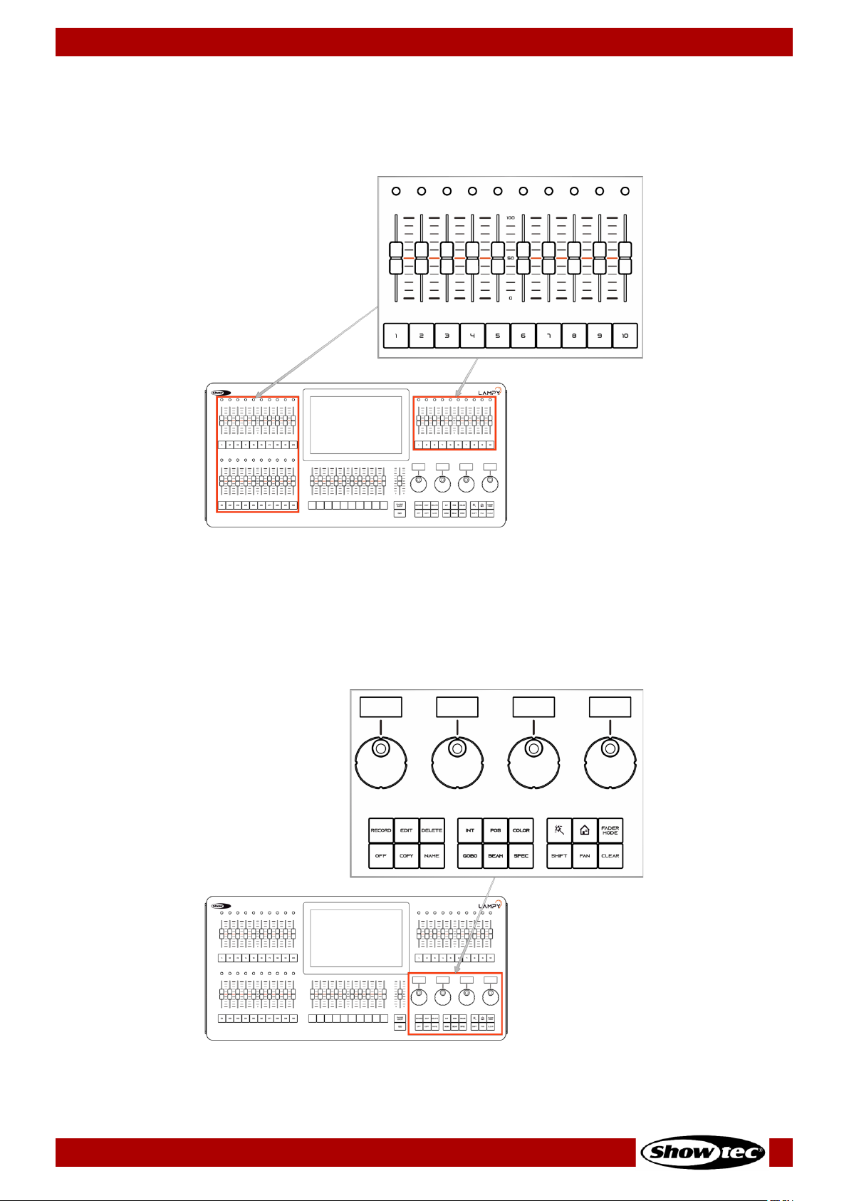
4.1.1. Multi-Function-Faders (MFF)
The LAMPY’s front panel consists of either 10 (LAMPY 20) or 30 (LAMPY 40) Multi-Function-Fader controls,
each consisting of a multicolor LED, a fader and a button. These may be switched between Fixtures,
Groups or Scenes and, depending on the mode, offer different options.
Fig. 3: Multi-Function Faders
4.1.2. Programming Section
This part of the LAMPY’s front panel contains all keys needed for programming. Take a few moments to
familiarize yourself with the buttons found here. It may seem like a lot to learn, but don't worry. You’ll be
training your muscle memory over time. Also, all controls for value entry can be found here.
Fig. 4: Programming Section

16
Showtec LAMPY Series
Product: 50733 / 50734 / 50735 / 50736
4.1.3. Playback Faders
The LAMPY’s front panel consists of multiple playback fader controls, each consisting of a fader and a
button under the fader. These playbacks may contain multiple cues. These faders are pageable and the
button function is assignable.
Fig. 5: Playback Faders
4.1.4. Master Playback Fader
The master playback fader may be used for more precise control over a selected playback. It consists of
a go, a pause / back button and a fader. The function of the fader may be configured in the Setup
Menu Show Settings view.
Fig. 6: Master Playback Fader

17
Showtec LAMPY Series
Product: 50733 / 50734 / 50735 / 50736
4.1.5. Touchscreen
The touchscreen of the LAMPY console is one of the key elements used for user interaction with the
LAMPY. It features an easy and intuitive graphical user interface.
Fig. 7: Touchscreen Display
18
Showtec LAMPY Series
Product: 50733 / 50734 / 50735 / 50736
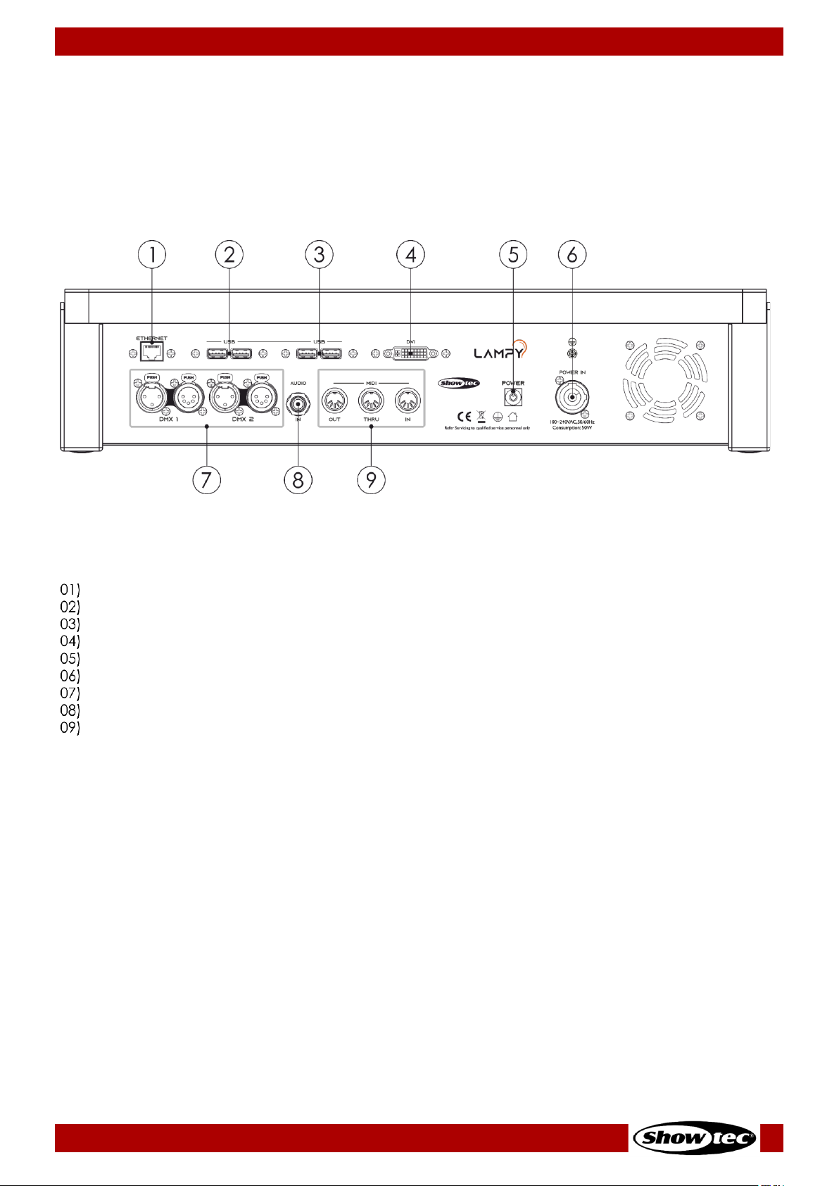
4.2. Back View
The back panel of the LAMPY20 and LAMPY40 are identical in terms of connectors.
Make sure to connect any external screen before booting up the console. The UI is at a fixed resolution of
1920 x 1080 (Full HD), so make sure your monitor supports the resolution.
The external screen may also be a touchscreen.
Fig. 8 LAMPY Back panel
Ethernet Port
USB 2.0 Ports
USB 3.0 (blue) Ports
DVI Port
Power Button
Power Input (PowerCon)
DMX Outputs
Audio Input
Midi Out / Thru / In

19
Showtec LAMPY Series
Product: 50733 / 50734 / 50735 / 50736
4.3. Product Specifications
The LAMPY is a hybrid programmer-based tracking console.
Hybrid means it may be used to either control conventional or moving light fixtures in the same easy-touse way.
Being a programmer-based Console, you always have the chance to override the LAMPY’s output
because the programming interface always has precedence.
“Tracking” as opposed to non-tracking defines that values are kept when changing between cues in one
playback until they are set to a different value.
LAMPY 20 1U
LAMPY 20 2U
LAMPY 40 1U
LAMPY 40 2U
Product Code
50733
50734
50735
50736
On-board Screen
10.1” Full Color Touchscreen
External Monitor
1x DVI (Full HD)
External Monitor Features
Limited
Full
Limited
Full
Playback Faders
10
Multi-Function Faders
10
30
Playback Pages
9 + 1 Template Page
Encoders
4
DMX Channels
512
1024
512
1024
DMX Universes
1
2 1 2
Ar-tNet
With Dongle
Yes
With Dongle
Yes
sACN
With Dongle
Yes
With Dongle
Yes
Fixture Views
1 2 1
2
Fixtures
Limited by DMX Channels
Max. channels per Fixture
120
Memories
100 Presets per Attribute Group, 100 Fixture-Groups
Playbacks
100
Scenes
10
30
MIDI In / Through / Out
Yes
OSC (Open Sound Control)
Yes
Time Code
Using MIDI-Timecode
Audio Input
Yes (6.3 mm jack)
Dongle
Optional
Included
Optional
Included
Input Voltage
100-240 V, 50/60 Hz
Power Consumption
50 W
60 W
Fuse
Internal fuse
Housing
Metal and flame-retardant plastic
Dimensions
505 x 345 x 128 mm
721 x 345 x 128 mm
Weight
8.8 kg
11.8 kg

20
Showtec LAMPY Series
Product: 50733 / 50734 / 50735 / 50736
4.4. Optional Accessories
LAMPY 20
LAMPY 40
Dustcover (product code)
50738
50739
Flight case (product code)
D7332
D7333
LAMPY DNGL (product code)
50737 (for the 1-universe consoles: 50733, 50735)
4.4.1. LAMPY DNGL Features
Using the LAMPY Dongle is only supported with the 1-universe versions of the console. The 2-universe
consoles have a built-in dongle.
The LAMPY DNGL unlocks the following features:
Without Dongle
With Dongle
External Monitor Features
Limited
Full
DMX Universes
1
2
DMX Channels
512
1024
Art-Net
No
Yes
sACN
No
Yes
Fixture Views
1
2
21
Showtec LAMPY Series
Product: 50733 / 50734 / 50735 / 50736
5. Installation
5.1. Safety Instructions for Installation
Attention
Place the device on stable surfaces only.
Installation Site Requirements
● The device can be used only indoors.
● The device can be placed on a flat, stable surface.
● The maximum ambient temperature ta = 40 °C must never be exceeded.
● The relative humidity must not exceed 50 % with an ambient temperature of 40 °C.
5.3. Connecting to Power Supply
DANGER
Electric shock caused by short-circuit
The device accepts AC mains power at 100–240 V and 50/60 Hz. Do not supply power at any other
voltage or frequency to the device.
This device falls under IEC protection class I. Make sure that the device is always electrically connected
to the ground (earth).
Before connecting the device to the socket-outlet:
● Make sure that the power supply matches the input voltage specified on the information label on
the device.
● Make sure that the socket-outlet has ground (earth) connection.
Connect the device to the socket-outlet with the supplied power plug.
5.4. Connecting Accessories
Attention
Connect all data cables before supplying power.
Disconnect power supply before connecting or disconnecting data cables.
01) Connect all optional accessories such as USB keyboard, mouse, external (touch)screen, etc. to the
console.
02) Connect DMX cables to the console’s DMX output ports.
03) If you are using Art-Net or sACN for data output (only available with LAMPY DNGL), also connect the
network cable to the consoles network port.
Art-Net is a protocol that uses TCP/IP to transfer large amount of DMX-512 data over an Ethernet network.
Art-Net 4 can support up to 32768 universes. Art-Net™ Designed by and Copyright Artistic Licence
Holdings Ltd.
22
Showtec LAMPY Series
Product: 50733 / 50734 / 50735 / 50736
6. Basic Concepts
6.1. Priority Concept
The general programming layer, called the “Programmer” always takes precedence over playbacks,
unless it is in “Blind”-programming mode. This may seem a bit strange, but in fact is very useful since the
programmer enables the user to gain additional control over the consoles output at any time.
The console allows multiple different playbacks and scenes to be run at the same time. The output values
are determined by the starting order of these playbacks or scenes.
The LAMPY’s priority concept is outlined here:
Priority
Level
Highest
6
Highlight button
5 Grand Master
4 Group Submasters
3 Programmer
2 Playbacks / Scenes
Lowest
1
Default values (as defined in the Fixture Library)
6.2. Tracking
6.2.1. Basic Idea
When a sequence of cues is programmed, the lighting console can store the information in one of two
ways: either it records the settings for all attributes of all the fixtures used in the playback, or it is only
recording the values that have changed. The latter is called tracking and was invented because
consoles in the early years had too little memory to store all the information. However, tracking is not
outdated and if it is used with understanding of the concept, it can help in many cases.
6.2.2. Tracking in a Nutshell
Imagine you come home late at night and it is already dark outside:
You open up your apartment’s main door (cue 1) and you switch on the light in the corridor (cue 2).
You close the door (cue 3), and go straight into the living room (cue 4), where you switch on the light as
well (cue 5).
The light in the corridor is still on, and the living room door is still open, because you did not change the
states of these.
Here is a closer look at what happened and at what would be stored in the cues, if we think of this chain
of events as a playback:
Cue
Entrance Door
Corridor Light
Living Room Door
Living Room Light
#1: Entrance
Open
#2: Light in corridor
On
#3: Close main door
Closed
#4: Living room door
Open
#5: Living room light
On

23
Showtec LAMPY Series
Product: 50733 / 50734 / 50735 / 50736
With tracking, the final state at the end of this sequence is:
Closed
On
Open
On
6.2.3. Tracking through Changes
One advantage of tracking is that changes can be ‘tracked through’ a series of cues. In the example
given above, if you did not close the main door in cue 3, the door would still be open until the end of this
imaginary playback.
Tracking can be very useful when you want to make the same change to a series of cues: for example,
you might have a series of cues that include a fixture that lights a part of the set in the same way
throughout. If you later want to change the intensity of that light, you may change it in the first cue. The
light appears and the change will track through to all the cues until the next change for this attribute of
this fixture.
6.2.4. Maintaining Tracking
Sometimes you may need to playback cues out of order: for example in a rehearsal situation where it
might be necessary to jump between different scenes or even acts.
The LAMPY console is taking care of maintaining the tracking state and will always calculate all values as
if the playback was played back in order.
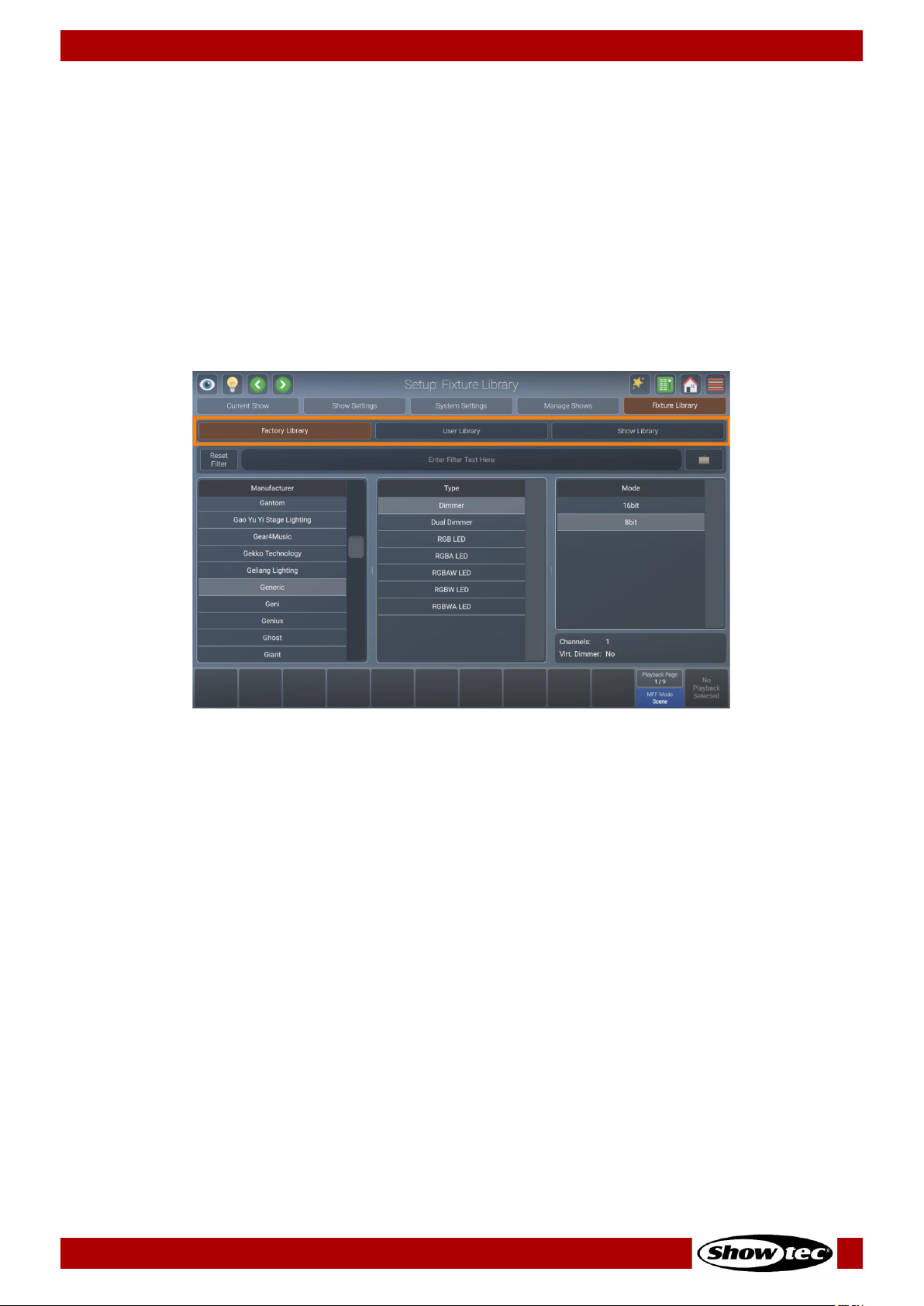
24
Showtec LAMPY Series
Product: 50733 / 50734 / 50735 / 50736
6.3. Fixture Library Basics
The console’s Fixture Library is divided into three parts:
● Factory Library
● User Library
● Show Library
Fixture types may easily be transferred between libraries using the magic wand button from the Setup
Menu’s Fixture Library view. If a fixture type is modified in the Show Library and those changes should be
available for later show files, transfer the fixture from the Show Library to the User Library.
Select the different libraries in the Fixture Library view, using the buttons at the top of the Fixture Library
page.
Fig. 9: The Fixture Library Tab
6.3.1. Factory Library
The Factory Library gets replaced with every software update. It contains around 20000 fixtures and is
maintained by AtlaBase. It is not editable by the user. However, it can be updated separately from the
Console OS.
6.3.2. User Library
The User Library is fully editable by the user and is not replaced or deleted during software updates. It is
stored on the USB flash drive of the console and its fixture types are available to all existing or new shows.
6.3.3. Show Library
The show library is a part of the show file. Before a fixture can be patched, it needs to be added to the
Show Library. The Show Library is stored in the show file and hence will be exported with the show file if a
backup of the show to a USB flash drive is made. Fixtures in the Show Library are not available to other
shows. To make the fixture types in the Show Library available to other shows, they need to be transferred
to the User Library first.
More information on creating or modifying Fixture Libraries can be found in Section 8.5.5. Fixture Library
View on Page 78.

25
Showtec LAMPY Series
Product: 50733 / 50734 / 50735 / 50736
7. The User Interface
7.1. The Internal Touchscreen Interface
The console utilizes an easy to use and intuitive graphical user interface (GUI). The following sections
explain the basics of finding your way around the GUI, in the internal as well as the external display.
The screen layout of the LAMPY consoles is divided into three different parts:
● Top toolbar
● Content area
● Bottom toolbar
Fig. 10: The Internal Screen Graphical User Interface
7.1.1. The “Top Toolbar”
The top toolbar is also divided into three parts:
● The left part shows buttons that control the programming interface.
● The center part shows the title of the current screen, or, if applicable, the current command
including possible options. If the current command is displayed in red, it is invalid or missing
information.
● The right part shows the main buttons to navigate through the user interface.
Fig. 11: The Top Toolbar

26
Showtec LAMPY Series
Product: 50733 / 50734 / 50735 / 50736
7.1.1.1. Programmer Buttons
Fig. 12: Programmer Buttons
The programmer buttons provide the following functions:
Name
Action
Action holding [S hif t] key
Blind
“Hides” the programmer content.
Tap again to show the content.
Highlight
Sets the selected fixtures to the “Highlight”
value defined in the library. Usually open
dimmer and 100 % brightness.
Tap again to deactivate the function. Very
useful for focusing.
Previous
Fixture
Steps through selected fixtures, in
backward direction.
All fixtures will be selected.
Next Fixture
Steps through selected fixtures, in forward
direction.
Even / Odd fixtures will be
selected.

27
Showtec LAMPY Series
Product: 50733 / 50734 / 50735 / 50736
7.1.1.2. Window Title / Active Command
The center part shows the title of the current screen, or, if applicable the current command including
possible options. If the current command is displayed in red, it is invalid or missing information. Most
commands such as record, edit or delete have additional options that may be accessed by tapping the
window title.
Fig. 13: Window Title
Fig. 14: Active Command

28
Showtec LAMPY Series
Product: 50733 / 50734 / 50735 / 50736
7.1.1.3. Main Navigation Buttons
The main navigation buttons are used to navigate through the different main views of the LAMPY user
interface.
Fig. 15: Navigation Buttons
The button functions and names are as follows:
Name
Action
Magic Wand
Opens a context-sensitive dialog box called “Action Menu”. It is greyed out if
not available.
Virtual
Executors
Switches to the Virtual Executor View.
If one of the virtual masters is active, the icon will be shown in orange color.
If the grand master or any of the speed masters is set to 0 %, the button will
turn red.
Home
Opens the home dialog box to select and program fixtures, groups, presets
and set fixture values as well as effects.
Menu
Opens the side menu, which gives access to other useful screens, such as the
setup screen, patch or DMX output view. (See Fig. 16)

29
Showtec LAMPY Series
Product: 50733 / 50734 / 50735 / 50736
Fig. 16: The Side Menu
7.1.1.4. The Content Area
The content area is used to display context-sensitive windows and dialog boxes, based on the selection
made from the top toolbar, hamburger menu or other user interface elements.
Fig. 17: The Content Area

30
Showtec LAMPY Series
Product: 50733 / 50734 / 50735 / 50736
7.1.2. The Bottom Toolbar
The bottom toolbar is used to show playback fader labels on the left side, playback page and multifunction-fader mode on the right part and the master fader label on the far-right side.
Fig. 18: Bottom Toolbar
For more information regarding to playback fader labels please see section 8.7.1. The Playback-Fader
Labels on page 141.
More about the fader page selector can be found in section 8.7.3. Playback Fader Pages on page 142.
More information about the multi-function faders can be found in section 8.8. Using the Multi-Function
Faders on page 161.

31
Showtec LAMPY Series
Product: 50733 / 50734 / 50735 / 50736
7.2. External Screen
The LAMPY supports one external monitor that may be connected to the DVI port on the rear of the
console. It needs to have a Full HD resolution of 1920 x 1080. Lower resolutions are not supported. The
LAMPY also supports external screens with touch functionality.
The LAMPY DNGL unlocks more functions in the external screen.
Keep in mind that the dongle is already included in the 2-universe versions of the console.
7.2.1. External Screen Functionality without the LAMPY DNGL
Without the dongle, the external screen always shows the fixtures view. The zoom factor and the viewport
can be set separately and are independent of each other (external vs internal screen).
At the bottom of the screen you will see fader labels for the multi-function faders, as well as the
corresponding fader mode.
Fig. 19: External Monitor – No LAMPY DNGL attached
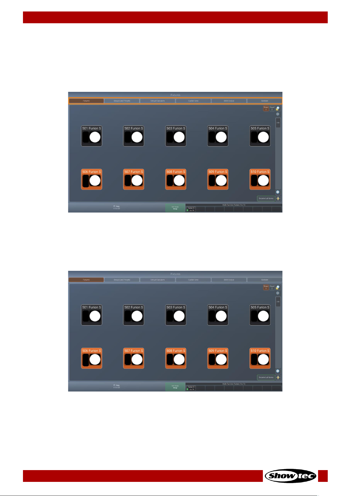
32
Showtec LAMPY Series
Product: 50733 / 50734 / 50735 / 50736
7.2.2. External Screen Functionality with the LAMPY DNGL
With the dongle attached, the external screen offers a toolbar at the top of the screen to change
between different views as indicated in the screenshot below.
At the bottom of the screen you will see fader labels for the multi-function faders, as well as the
corresponding fader mode.
Fig. 20: External Monitor Navigation – LAMPY DNGL attached
7.2.2.1. The Fixtures View
The fixture view is identical to the internal screen fixture view, however all editing functions have to be
made with the console’s internal touchscreen.
Fig. 21: External Monitor Fixtures View – LAMPY DNGL attached

33
Showtec LAMPY Series
Product: 50733 / 50734 / 50735 / 50736
7.2.2.2. The Groups and Presets View
The groups and presets view shows both groups and presets at the same time. This is a very helpful screen
during programming.
Fig. 22: External Monitor Groups and Presets – LAMPY DNGL attached
7.2.2.3. The Virtual Executor View
The Virtual Executor view shows the same contents as the Virtual Executor view on the internal screen. This
screen is very helpful if running a live, busking show where you do not know what is about to happen.
Fig. 23: External Monitor Virtual Executor – LAMPY DNGL attached

34
Showtec LAMPY Series
Product: 50733 / 50734 / 50735 / 50736
7.2.2.4. The Cuelist View
The Cuelist View is very similar to the Edit Playback Fader view. It will always show the selected playback.
This is a very helpful screen during structured shows.
Fig. 24: External Monitor Cuelist View – LAMPY DNGL attached
7.2.2.5. The DMX Output View
The DMX Output view resembles the internal screen output view. It is helpful for troubleshooting purposes.
Fig. 25: External Monitor DMX Output View – LAMPY DNGL attached
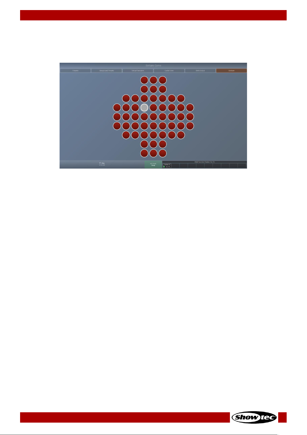
35
Showtec LAMPY Series
Product: 50733 / 50734 / 50735 / 50736
7.2.2.6. Solitaire Game
Solitaire is a simple game to help you kill some time, whenever you have to wait for other people to finish
their tasks.
Fig. 26: External Monitor Solitaire Game – LAMPY DNGL attached
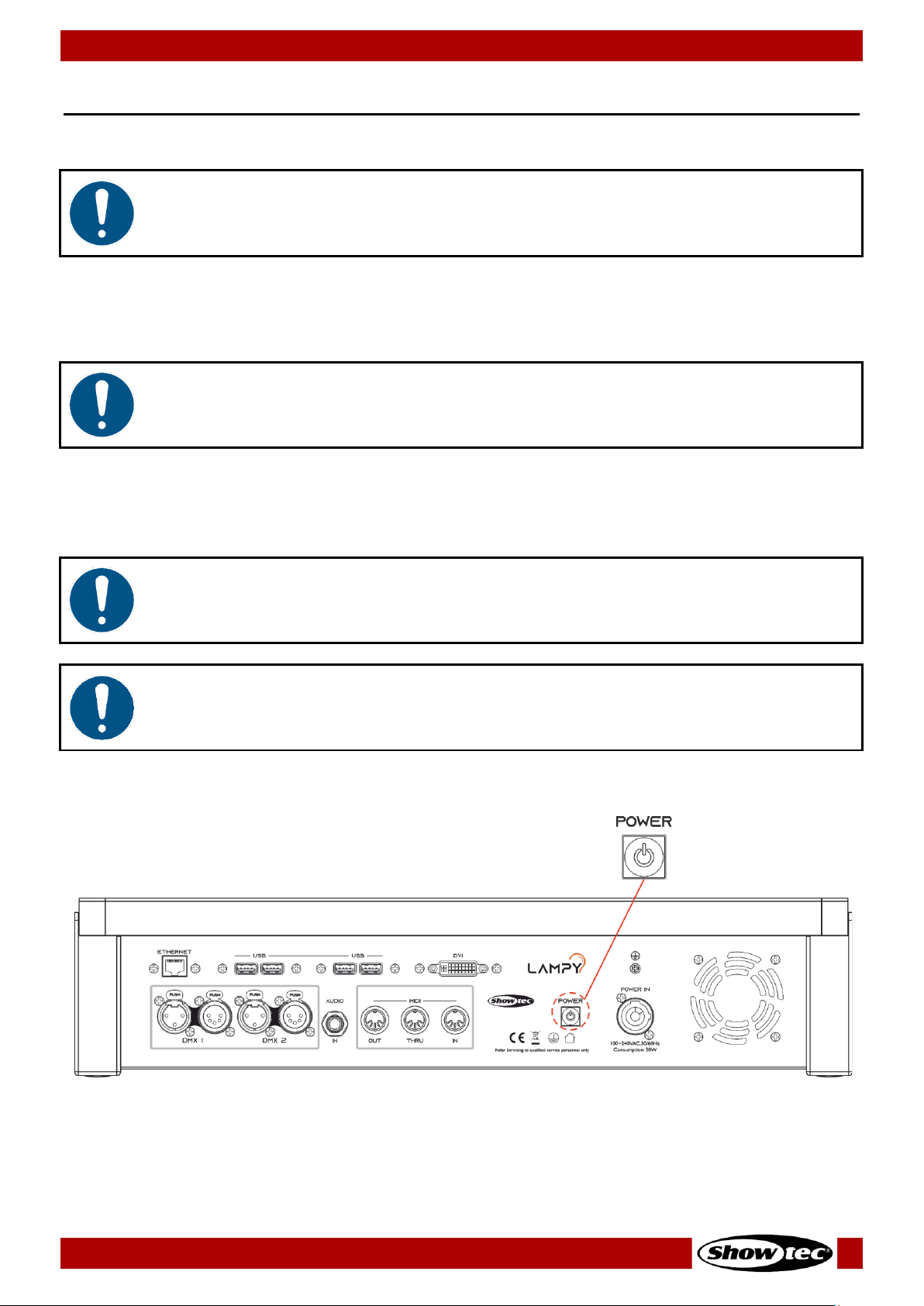
36
Showtec LAMPY Series
Product: 50733 / 50734 / 50735 / 50736
8. Operation
8.1. Safety Instructions for Operation
Attention
This device must be used only for the purposes it is designed for.
This device is intended for professional use as a lighting controller. It is suitable only for indoor installation.
This device is not suitable for households.
Any other use, not mentioned under intended use, is regarded as non-intended and incorrect use.
Attention
Power supply
Before connecting the device to the power supply, make sure that the current, voltage and frequency
match the input voltage, current and frequency specified on the information label on the device.
8.2. Starting the Console
Attention
The device must be placed on a stable, flat service in a dry, dust-free environment.
Attention
Connect all data cables before supplying power.
Disconnect power supply before connecting or disconnecting data cables.
Press the power button on the back of the console to start the console.
Fig. 27: Power Button

37
Showtec LAMPY Series
Product: 50733 / 50734 / 50735 / 50736
During the boot process a boot menu will be shown.
This boot screen provides several maintenance utilities; however, it will continue to automatically boot
the Console OS without user intervention.
Once the system is ready to use the welcome screen, as shown below will appear.
From this screen you may either start a new show file or load an existing show from the console’s built-in
memory or a USB flash drive.
You may also access the setup menu by tapping the cog button, or shutdown / reboot the console by
tapping the power button shown at the bottom of the screen.
More Info in regard to the setup menu can be found here: 8.5. The Setup Menu on page 49.
Fig. 28: Welcome Screen

38
Showtec LAMPY Series
Product: 50733 / 50734 / 50735 / 50736
8.3. Working with Shows
Show files contain all your show-related settings like fixture schedule, patching, input settings, groups,
presets, cues, master assignments, etc. Multiple shows can be stored on the console and the amount of
shows is only limited by hard disk memory. However, we advise you to regularly backup old shows to a
USB flash drive and delete them from the console’s memory.
8.3.1. Creating a New Show
A show stores all information like patch, fixtures, groups, presets, playback faders, etc. To start a new
show, do as follows:
01) On the touchscreen display, tap the Create New Show button.
02) A keyboard dialog box will appear and you can enter the name of the show to be created. Enter
the name by using the attached USB keyboard anytime the keyboard dialog box is shown.
03) As soon as you press the enter button a new show with your chosen name is created.
Fig. 29: Welcome Screen - New Show
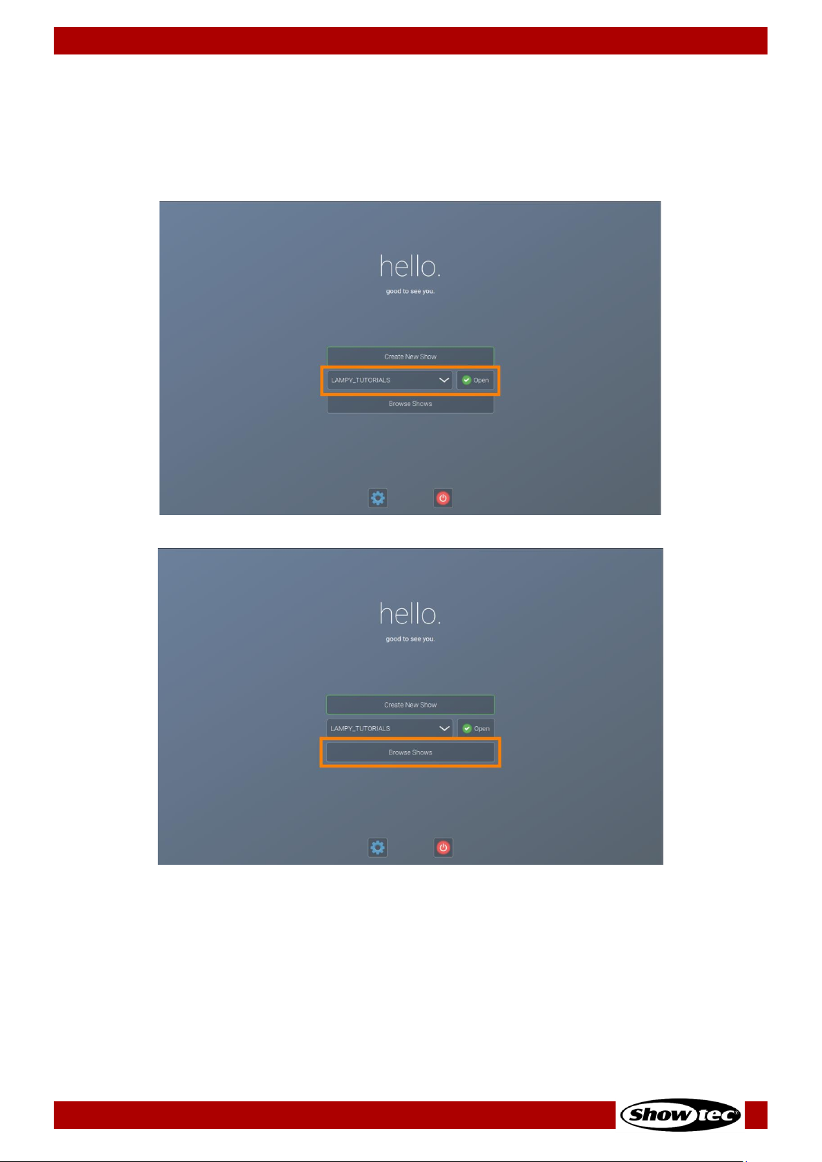
39
Showtec LAMPY Series
Product: 50733 / 50734 / 50735 / 50736
8.3.2. Loading a Show
On the touchscreen display, select the show you want to open up from the drop-down menu. After
selecting the desired show to load, tap the Open button.
Alternatively, you may also see more detailed info about existing shows or how to import a show from a
USB flash drive by tapping the Browse Shows button.
Fig. 30: Welcome Screen - Loading a Show by using the Dropdown Menu
Fig. 31: Welcome Screen - Loading a Show usingthe Browse Shows Button

40
Showtec LAMPY Series
Product: 50733 / 50734 / 50735 / 50736
8.3.3. Saving the Show File
We recommend saving your show every once in a while. You can do this from the side menu:
01) Tap the menu button. The side menu will open.
02) Tap the save button at the bottom of the side menu, indicated by a floppy disk button.
Fig. 32: Show Quick save Button

41
Showtec LAMPY Series
Product: 50733 / 50734 / 50735 / 50736
8.4. Adding and Patching Fixtures
“Adding and Patching Fixtures” is the process of telling the console what kind of fixtures you are using
and assigning DMX addresses to them.
If you just started a new show file or loaded a show file without fixtures, the console will automatically
open the patch view. Otherwise, it may be accessed as follows:
01) Open the side menu by tapping the menu button.
02) Tap the patch button.
Fig. 33: Side Menu –Opening the Patch View
8.4.1. The Patch Table
The patch table gives you an important overview of used fixtures, used addresses, fixture types, etc.
Fig. 34: The Patch Table

42
Showtec LAMPY Series
Product: 50733 / 50734 / 50735 / 50736
The table contains the following columns (from left to right):
Column name
Description
ID
This column shows the ID of the fixture. This is a unique number which may be used
for indicating which fixture is which.
Manufacturer
This is the manufacturer of the fixture.
Type
This column displays the fixture type.
Mode
DMX mode of the fixture.
Channels
Amount of DMX channels this fixture occupies.
Name
User-given name of the fixture in the show file.
Patch
Indicates the fixtures DMX address (Universe – Channel).
Invert Pan
Indicates if pan is inverted.
Invert Tilt
Indicates if tilt Inverted.
8.4.2. The Patch Actions Menu
The Patch Actions menu is opened by tapping the magic wand button on the keyboard or at the top
toolbar. It gives you access to most functions used in the patch view.
You may select which fixture your desired changes are applied to, by selecting them before opening this
screen, either in the patch table by tapping / dragging, or by using the fixture, group faders or views.
Fig. 35: Patch Action Menu
Button
Function
Add Fixture
Is used to add fixtures to the show file.
Delete Fixture
Is used to delete selected fixtures.
Change Patch
Is used to change the DMX address of one or more selected fixtures.
Rename
Is used to change the name of one or more selected fixtures.
Invert Pan / Tilt
Is used to invert pan or tilt of one or more selected fixtures.
Set User Number
Is used to change the ID of one or more selected fixtures.

43
Showtec LAMPY Series
Product: 50733 / 50734 / 50735 / 50736
8.4.3. Adding Fixtures to the Show File
01) Open the actions menu by tapping the magic wand button.
02) Tap Add Fixture. The display will show:
Fig. 36: Add Fixtures – Select Fixture from Show Library
03) To add a fixture from the built-in library, select Add from Factory Library. If you want to add a user
created library, tap Add from User Library. The Select Fixture Library view is shown.
Fig. 37: Add Fixture to Show Library – Select Fixture
04) Select the manufacturer, fixture type and mode from the lists, or enter a search text into the full-text
search field by typing it with a USB keyboard. You may also open the on-screen keyboard by
tapping the keyboard button next to the text field.
05) After selecting the fixture type, tap Ok. A dialog box asking you for the fixture count will be shown.

44
Showtec LAMPY Series
Product: 50733 / 50734 / 50735 / 50736
Fig. 38: Add Fixture – Enter Count
06) Enter the number of fixtures you want to add using the keypad. The console will automatically
suggest a user number for the fixture, which you may change if you like. On this screen you can also
invert pan and / or tilt for all the new fixtures.
07) Tap Next when done.
Fig. 39: Add Fixture – Assign Address
08) Set the starting address of the fixtures you want to add. You may select:
● No Patch, which will leave the fixtures without any DMX assignment.
● Manual Patch to set universe, starting address (by either typing it, or by using the Select Address
button) and gap between fixtures using the Block Patching option manually.
● Auto Patch, which will patch the fixtures automatically onto the selected universe.
09) Tap Patch when done.

45
Showtec LAMPY Series
Product: 50733 / 50734 / 50735 / 50736
Fig. 40: Add Fixtures - Success
10) LAMPY will indicate if the patch was successful. If so, you may now place the fixtures on the “Fixtures
View” by tapping Next or skip to do this at a later point by tapping Close.
More information about laying out fixtures in the Fixtures View can be found here: 8.6.1.7. Arranging
Existing Elements on page 96.
8.4.4. Deleting Fixtures from the Show file
01) Select the fixtures you want to delete in either the patch view or by any of the other methods.
02) Open the actions menu by tapping the magic wand button.
03) Tap Delete Fixtures. A confirmation dialog box will be shown.
04) Tap Ok.
8.4.5. Changing the Patch of Existing Fixtures
01) Select the fixtures you want to change the address of, in either the patch view or by any of the other
methods.
02) Open the action menu by tapping the magic wand button.
03) Tap Change Patch. The following dialog box will be shown.
Fig. 41: Change Patch dialog box

46
Showtec LAMPY Series
Product: 50733 / 50734 / 50735 / 50736
04) Set the new start address of the selected fixtures. You may select:
● Unpatch, which will leave the fixtures without any DMX assignment.
● Manual Patch to set universe, starting address (by either typing it, or by using the Select Address
button) and gap between fixtures using the Block Patching option manually.
● Auto Patch, which will patch the fixtures automatically onto the selected universe.
05) Tap Patch when done.
8.4.6. Changing the Name of Existing Fixtures
01) Select the fixtures you want to change the name of, in either the patch view or by any of the other
methods.
02) Open the action menu by tapping the magic wand button.
03) Tap Rename. An on-screen keyboard will be shown.
Fig. 42: Change Fixture Name Keyboard
04) Type the new name of the fixture by using the on-screen keyboard or by using a USB keyboard. If the
Auto Number button is active, the console will assign a number to the name, in the order the fixtures
were selected.
05) Tap Enter to rename the selected fixtures.

47
Showtec LAMPY Series
Product: 50733 / 50734 / 50735 / 50736
8.4.7. Invert Pan or Tilt for Existing Fixtures
01) Select the fixtures you want to change the pan / tilt Invert of, in either the patch view or by any of
the other methods.
02) Open the action menu by tapping the magic wand button.
03) Tap Invert Pan or Tilt. The following dialog box will be shown.
Fig. 43: Invert Pan / Tilt dialog box
04) Set the new values for pan and tilt invert by selecting them from the drop-down menus.
05) Tap Ok to accept the changes.
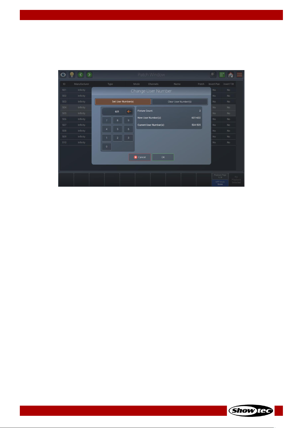
48
Showtec LAMPY Series
Product: 50733 / 50734 / 50735 / 50736
8.4.8. Changing User ID for Existing Fixtures
01) Select the fixtures you want to change User ID of, in either the patch view or by any of the other
methods.
02) Open the action menu by tapping the magic wand button.
03) Tap Set User Number(s). The following dialog box will be shown.
Fig. 44: Change User Number dialog box
04) Set the new values for the user number of the fixture.
05) Tap Ok to accept the changes.

49
Showtec LAMPY Series
Product: 50733 / 50734 / 50735 / 50736
8.5. The Setup Menu
The setup menu is the place where all system and show-related settings are made. This includes, for
example setting the IP address of the console or editing the fixture library or managing shows.
When no show file is open, you can only adjust system-related settings.
Opening the Setup Menu in a Show
01) Open the side menu by tapping the menu button.
02) Tap the button that shows a cog button as a symbol. We’ll refer to this button as “Setup”-button.
Fig. 45: Side Menu – Opening the Setup View
Opening the Setup Menu from the Welcome Screen
01) Tap the button that shows a cog button as a symbol. We’ll refer to this button as “Setup”-button.
Fig. 46: Welcome Screen – Opening the Setup View
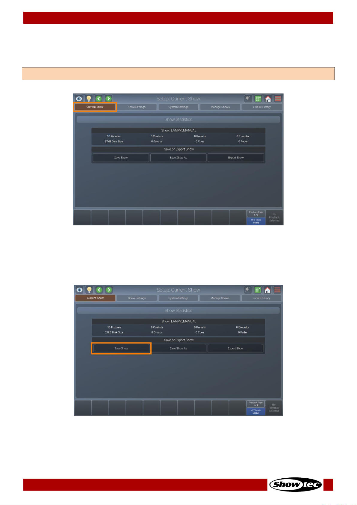
50
Showtec LAMPY Series
Product: 50733 / 50734 / 50735 / 50736
8.5.1. Current Show View
The Current Show view displays statistics about the current show. It also offers the option to save your
show, save it to a different file and to export the current show to a USB flash drive.
Fig. 47: The Current Show view
8.5.1.1. Saving the Show File
You may easily save your show from the Current Show view of the setup menu by tapping the Save Show
button.
Fig. 48: Current Show – Save Show
Note: The Current Show view is only shown if you have opened the setup menu in a show file.
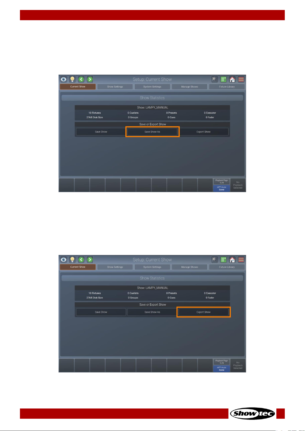
51
Showtec LAMPY Series
Product: 50733 / 50734 / 50735 / 50736
8.5.1.2. Saving the Show File under a New Name
We recommend to periodically save your show file as a new file.
01) Open the Current Show view from the setup menu.
02) Tap Save Show As. An on-screen keyboard will be shown. Enter the new show file name and tap
Enter to complete the process.
Fig. 49: Current Show – Save Show As
8.5.1.3. Exporting the Show File to USB
It is useful to periodically save a copy of the show file to a USB flash drive.
01) First plug the USB flash drive into one of the console’s USB ports.
02) Open the Current Show view in the setup menu.
03) Tap Export Show. A wizard that guides you through the process will open.
Fig. 50: Current Show – Export Show
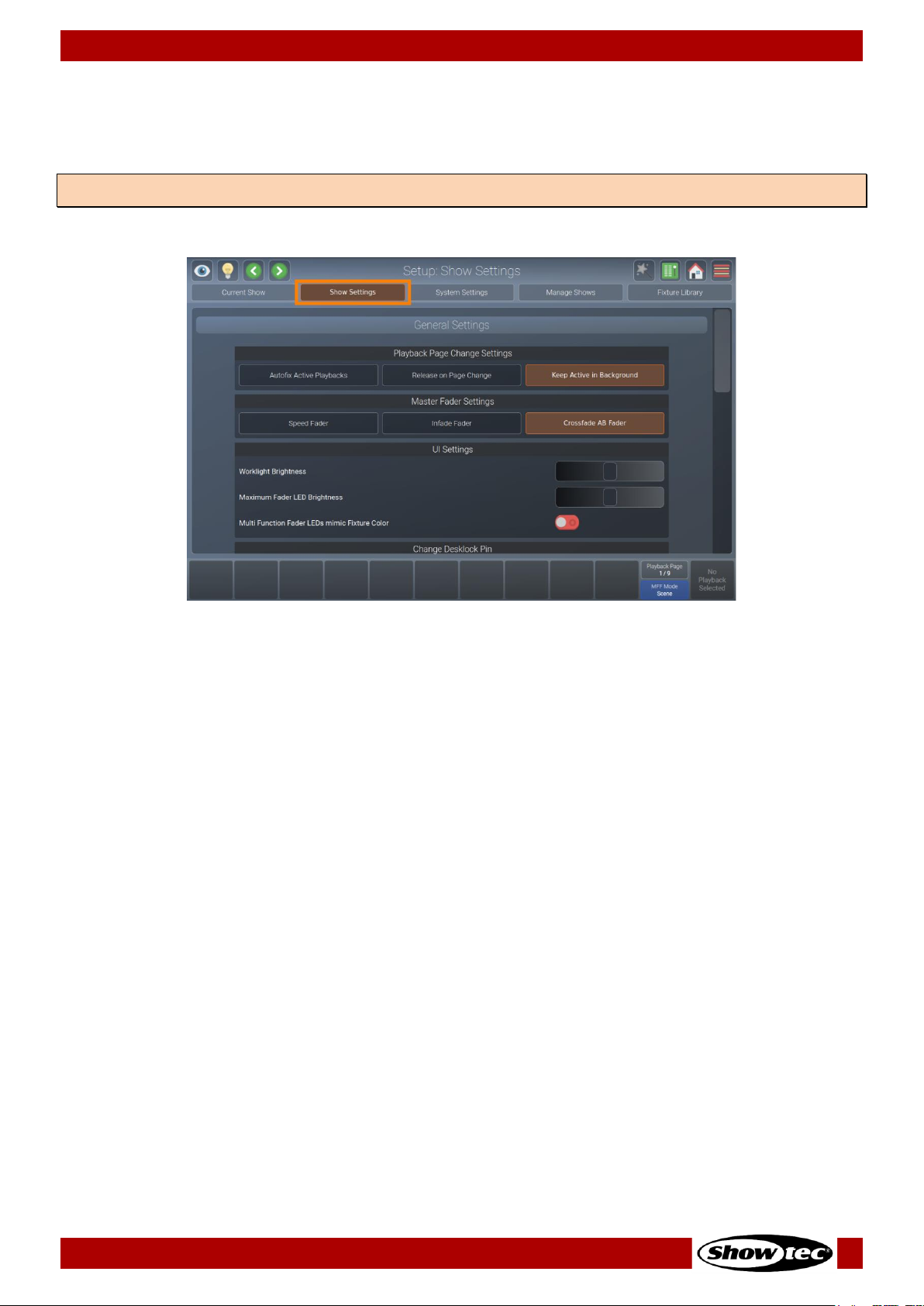
52
Showtec LAMPY Series
Product: 50733 / 50734 / 50735 / 50736
8.5.2. Show Settings View
The Show Settings view contains all show-related settings for the current show such as the Worklight
Brightness, Multi-Fader LED’s behavior and configuration of inputs and outputs of the console.
Fig. 51: The Show Settings view
Note: The Show Settings view is only shown if you have opened the Setup Menu in a Show file.
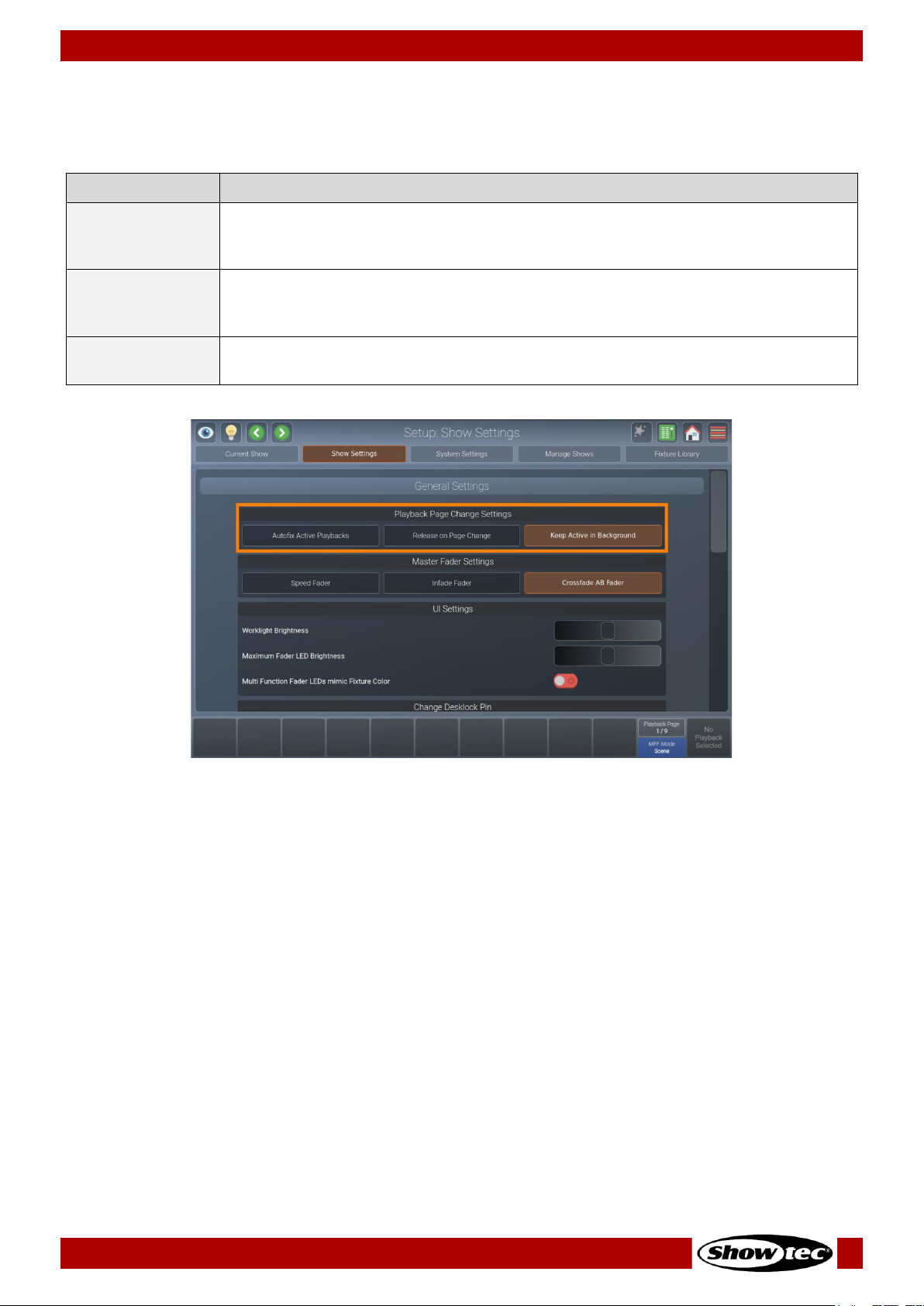
53
Showtec LAMPY Series
Product: 50733 / 50734 / 50735 / 50736
8.5.2.1. Playback Page Change Settings
The Playback Page Change Settings group box allows to specify what should happen if you change the
active playback page. The following table outlines the different settings and what they do:
Button
Function
Auto fix Active
Playbacks
Auto fix is a convenient function that is used to carry over running playbacks to the
new playback page. The “old” playback will be overlaying other playbacks on
the new page, until it is switched off.
Release on Page
Change
With this option selected, the console will automatically release all playbacks on
the old fader page when the active page is changed. Playbacks assigned to the
template page will not be released.
Keep Active in
Background
When this option is selected, the playbacks will be kept running “in the
background”.
Fig. 52: Show Settings – Playback Page Change Settings

54
Showtec LAMPY Series
Product: 50733 / 50734 / 50735 / 50736
8.5.2.2. Master Fader Settings
The Master Fader Settings group box specifies the behavior of the master playback fader. The following
table outlines the different settings and what they do:
Button
Function
Speed Fader
The master fader will act as a speed fader for the selected playback, altering all
timings of the assigned playback, meaning 100 % is the speed as programmed –
and everything below is slowed down relatively.
Infade Fader
The master fader will continually crossfade the output of all parameters that are
set to “Fade” in the library.
Crossfade AB
Fader
With this option the master fader can be used to crossfade from cue to cue in a
playback. This is a very common setting when controlling a theatric play.
Fig. 53: Show Settings – Master Fader Settings
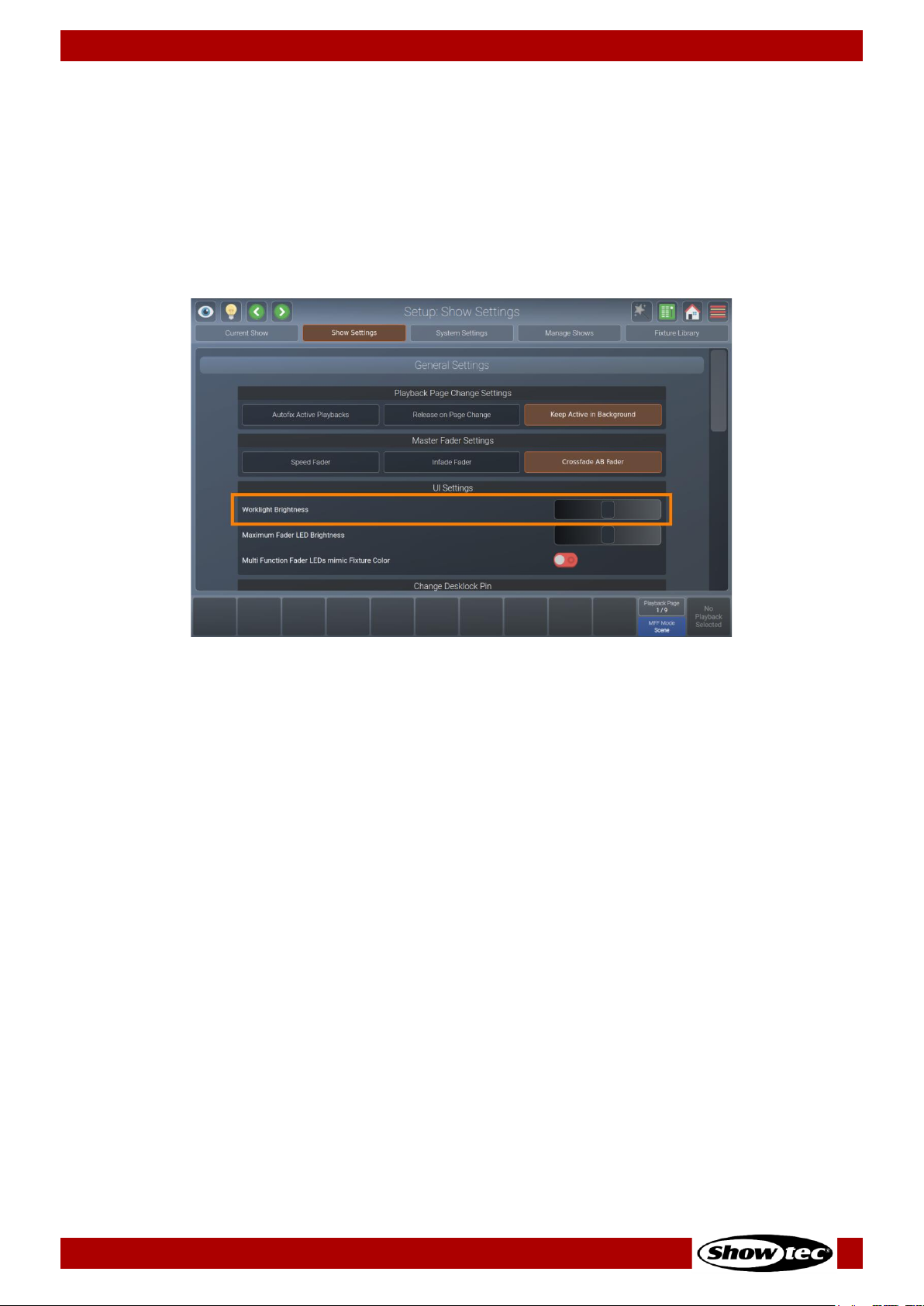
55
Showtec LAMPY Series
Product: 50733 / 50734 / 50735 / 50736
8.5.2.3. Changing the Worklight Brightness
The Worklight is the LED strip at the front side of the console, which may be used to light up running orders
or other documents. It can also be useful to light up a USB keyboard.
In order to adjust the brightness, please do as follows:
01) Open the setup menu.
02) Change to the Show Settings view.
03) Scroll down to Worklight Brightness.
04) Adjust the on-screen slider according to your preference.
Fig. 54: Show Settings – Work light Brightness
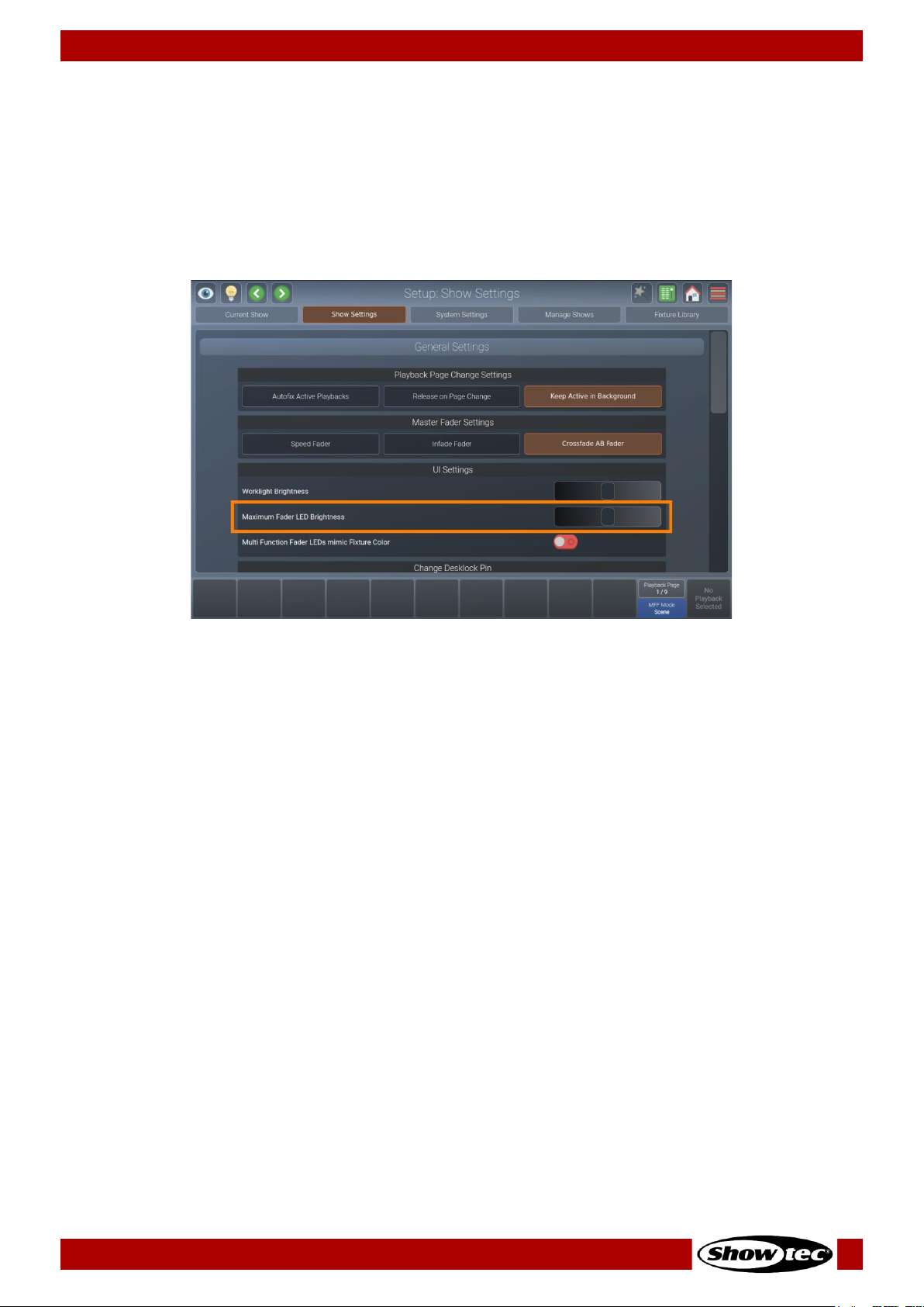
56
Showtec LAMPY Series
Product: 50733 / 50734 / 50735 / 50736
8.5.2.4. Changing the Brightness of the Multi-Function-Fader LED
The LEDs of the Multi-Function Faders may also be adjusted in brightness.
In order to adjust the brightness, please do as follows:
01) Open the setup menu.
02) Change to the Show Settings view.
03) Scroll down to Maximum Fader LED Brightness.
04) Adjust the on-screen slider according to your preference.
Fig. 55: Show Settings – Maximum Fader LED Brightness

57
Showtec LAMPY Series
Product: 50733 / 50734 / 50735 / 50736
8.5.2.5. Setting the Multi-Function-Fader LEDs to Mimic Fixture Color
The Multi-Function-Fader LEDs can either just indicate the current multi-function fader mode and
selection. Or in fixture mode it can indicate the current fixture color. By default, the LEDs always light up in
the color of the selected fader mode.
Please note that this setting only affects the LEDs behavior when the multi-function faders are set to
fixture mode.
To change the behavior of the LEDs:
01) Open the setup menu.
02) Change to the Show Settings view.
03) Scroll down to Multi-Function Fader LEDs Mimic Fixture Color.
04) Toggle the on-screen switch to turn the fixture color indication on or off.
Fig. 56: Show Settings – MFF Mimic Fixture Color

58
Showtec LAMPY Series
Product: 50733 / 50734 / 50735 / 50736
8.5.2.6. Changing the Desklock PIN
The LAMPY gives you the option to lock your desk and only allow authorized persons to access and
unlock the console. The desklock PIN is saved in the show file and you can lock each show separately.
To learn how to lock the console, please see section 8.12. Locking the Console on page 185.
To change the default PIN code, please do as follows:
01) Open the setup menu.
02) Change to the Show Settings view.
03) Scroll down to Change Desklock PIN.
04) Enter your old PIN code into the current PIN text field (only if you previously changed the PIN).
05) Enter the new PIN in the New PIN and Repeat New PIN text-fields.
06) Tap Change PIN.
Fig. 57: Show Settings – Desk lock PIN
The default PIN is 0000 (four times zero). If you have set and forgotten the PIN code, please contact
Showtec support for the master PIN, which may also be used to create a new PIN code.

59
Showtec LAMPY Series
Product: 50733 / 50734 / 50735 / 50736
8.5.2.7. Changing the Autosave Settings
LAMPY automatically saves your show file every 10 minutes. If desired, you may also disable this autosave
functionality.
If you want to turn Autosave on or off, please do as follows:
01) Open the setup menu.
02) Change to the Show Settings view.
03) Scroll down to Show Autosave.
04) Toggle the on-screen switch to either turn Autosave on or off.
Fig. 58: Show Settings – Autosave

60
Showtec LAMPY Series
Product: 50733 / 50734 / 50735 / 50736
8.5.2.8. Enabling the Open Sound Control (OSC) Input
In case you want to remotely control your LAMPY console by using an OSC Remote (such as TouchOSC
for Android or iOS), you need to enable the OSC Input.
The console shows the necessary port numbers for OSC in the OSC Group Box after activation. You can
also see incoming messages and the number of connected clients.
The QR Code on the right brings you directly to the TouchOSC website.
The LAMPY OSC protocol specification can be found here: 9.1. Open Sound Control on page 186.
To enable or disable OSC, please do the following:
01) Open the setup menu.
02) Change to the Show Settings view.
03) Scroll down to Open Sound Control (OSC).
04) Toggle the on-screen switch to either turn OSC on or off.
Fig. 59: Show Settings – Open Sound Control (OSC)

61
Showtec LAMPY Series
Product: 50733 / 50734 / 50735 / 50736
8.5.2.9. Enabling and Configuring the Sound Input
You may use any line level audio source to trigger cues and chases using the LAMPY.
The sound input is analyzed in Bass, Mid and High levels which are individually configurable in their
individual levels.
To enable or disable Sound Input, please do the following:
01) Open the setup menu.
02) Change to the Show Settings view.
03) Scroll down to Sound Input.
04) Toggle the on-screen switch to either turn Sound Input on or off.
Fig. 60: Show Settings – Sound Input

62
Showtec LAMPY Series
Product: 50733 / 50734 / 50735 / 50736
Setting the Sound Input Level / Threshold
You may configure the sound input threshold as follows:
01) Open the setup menu.
02) Change to the Show Settings view.
03) Scroll down to Sound Input.
04) Make sure the Sound Input on-screen switch is set to On.
05) Connect your audio signal to the 6.3 mm jack on the rear of the console. For the best results use a
symmetric signal cable.
06) Play back Audio from your Audio source at the intended volume.
07) Adjust the Bass, Mid and High sliders. The white lines in the input indicators indicate the level the
sound signal has to reach to be triggered (top line) and the sound signal has to fall below the
indicator line to be able to be triggered again.
Fig. 61: Show Settings – Sound Input Signal Level

63
Showtec LAMPY Series
Product: 50733 / 50734 / 50735 / 50736
8.5.2.10. Enabling the Time-Code Input
LAMPY’s ability to synchronize playbacks to an incoming timecode signal may be used to keep your
lighting and audio show in sync.
Timecode is only supported via MIDI at the moment. The LAMPY automatically recognizes the framerate
of your incoming timecode signal and displays the current timecode status in the Timecode Input group
box. No further settings are required.
You may enable or disable the timecode input as follows:
01) Open the setup menu.
02) Change to the Show Settings view.
03) Scroll down to Timecode Input.
04) Set the Timecode on-screen switch to on or off.
Fig. 62: Show Settings – Timecode Input
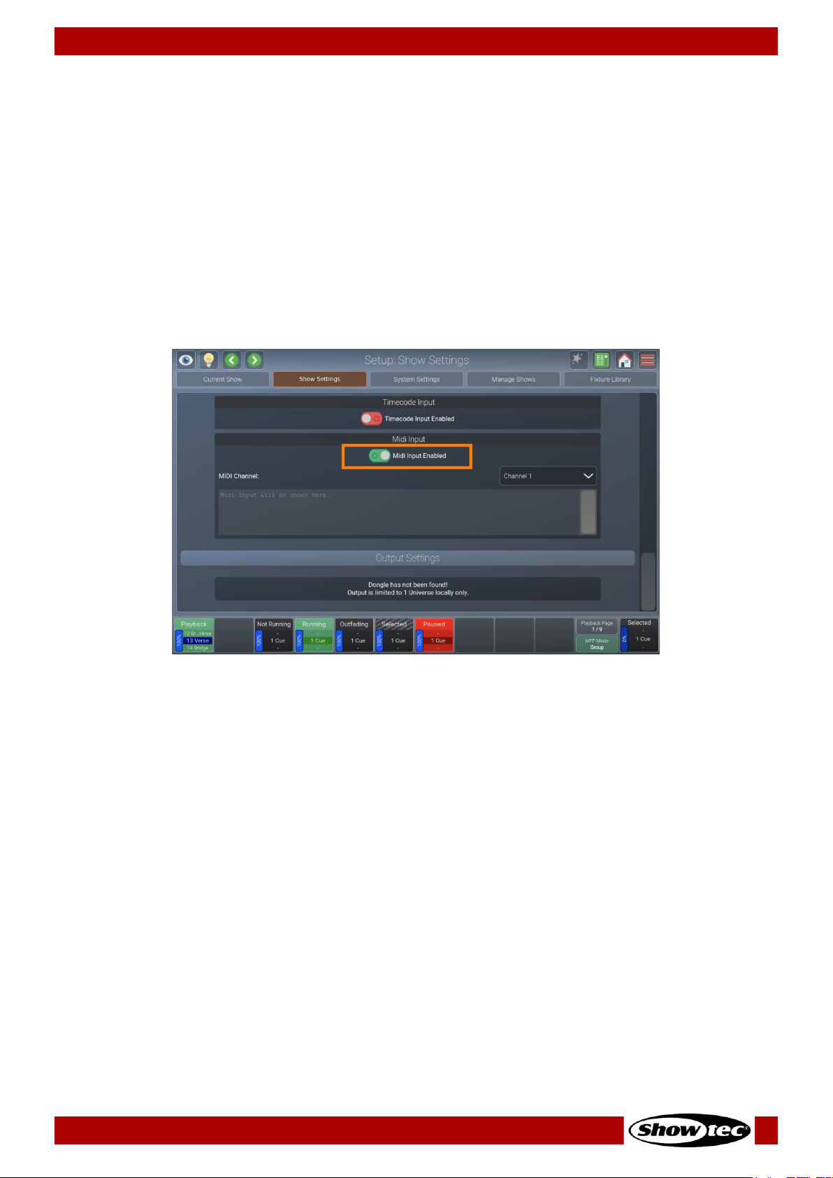
64
Showtec LAMPY Series
Product: 50733 / 50734 / 50735 / 50736
8.5.2.11. Enabling the MIDI Input
You may remotely control the LAMPY console with any MIDI device that allows to configure its MIDI
output. Once MIDI input is enabled, the console will display any incoming MIDI messages in the status text
field in the MIDI group box.
MIDI Input does not need to be enabled in order to be able to use the aforementioned Timecode Input.
To learn more about the LAMPY’s MIDI protocol, please read section 9.2. MIDI Input on page 190.
You may enable or disable the MIDI input as follows:
01) Open the setup menu.
02) Change to the Show Settings view.
03) Scroll down to MIDI Input.
04) Set the MIDI on-screen switch to on or off.
Fig. 63: Show Settings – MIDI Input
Setting the MIDI Channel
You may set the MIDI channel by selecting it from the drop-down menu shown in the MIDI group box
after enabling the MIDI Input.
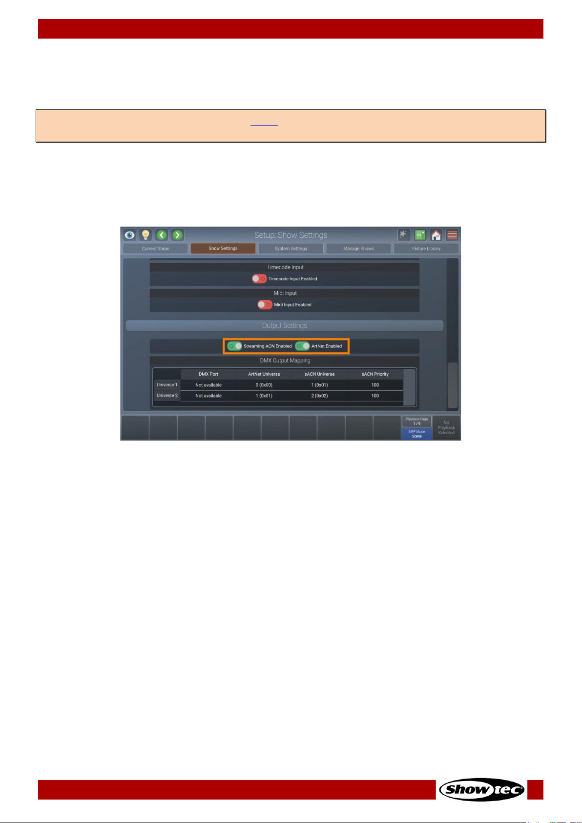
65
Showtec LAMPY Series
Product: 50733 / 50734 / 50735 / 50736
8.5.2.12. Enabling and Configuring the DMX Output via Art-Net or sACN
Art-Net and sACN are two popular protocols to transmit DMX data via ethernet. LAMPY supports both
protocols and enables you to configure both of them independently.
You may enable or disable DMX Output via network protocols as follows:
01) Open the setup menu.
02) Change to the Show Settings view.
03) Scroll down to Output Settings.
04) Set the on-screen switch for Art-Net or sACN to on or off.
Fig. 64: Show Settings – DMX Output Configuration
Setting Art-Net or sACN Universe and Priority
If you want to change the Art-Net and / or sACN mapping, please double-tap or long-tap the
corresponding cell of the DMX Output Mapping table.
A dialog box will open asking you to input a new universe or priority number. Tap Enter when done.
Note: You need a LAMPY DNGL (order code 50737), which may be either purchased separately or comes
factory installed in the 2-universe versions of the console.

66
Showtec LAMPY Series
Product: 50733 / 50734 / 50735 / 50736
8.5.3. System Settings View
The System Settings view contains all system-related settings for the console, such as keyboard layout,
date or time, network settings, etc.
Fig. 65: The System Settings view
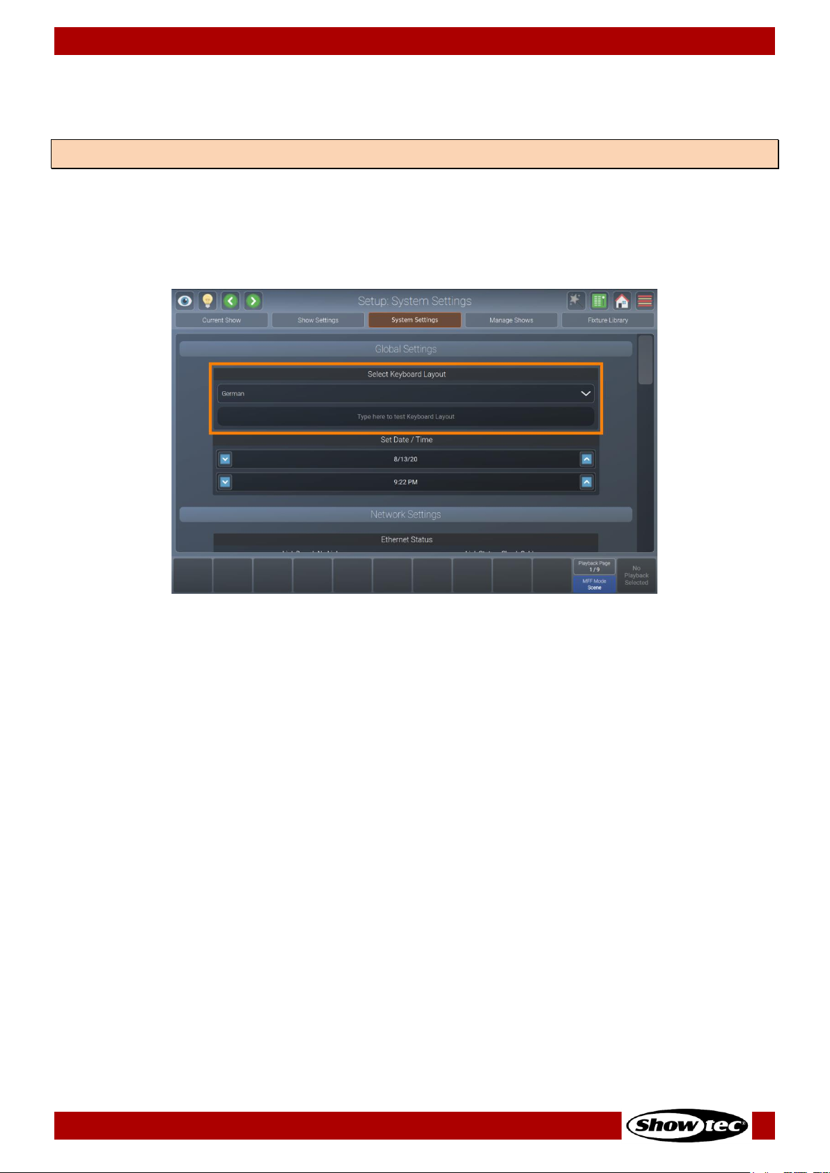
67
Showtec LAMPY Series
Product: 50733 / 50734 / 50735 / 50736
8.5.3.1. Setting the USB Keyboard Layout
It may be desirable to setup the keyboard layout of an external USB keyboard.
Please follow these steps to do so:
01) Open the setup menu.
02) Change to the System Settings view.
03) Scroll to Select Keyboard Layout.
04) Select the appropriate Keyboard Layout from the drop-down menu.
Fig. 66: System Settings – Set Keyboard Layout
Note: The keyboard layout setting does not affect the on-screen keyboard
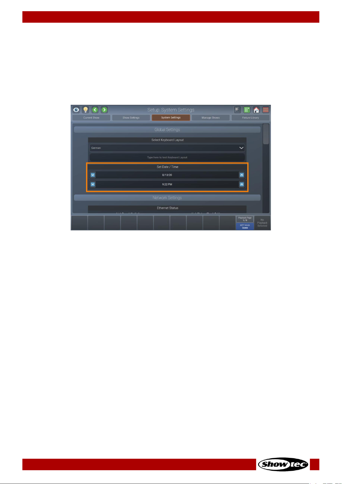
68
Showtec LAMPY Series
Product: 50733 / 50734 / 50735 / 50736
8.5.3.2. Setting the Console’s Date and Time
Please follow these steps to set the console’s Date and Time:
01) Open the setup menu.
02) Change to the System Settings view.
03) Scroll to Set Date / Time.
04) Select the appropriate date and time by tapping the text fields to select if you want to change the
day, month, etc. Use the up and down buttons, next to the text fields, to change the selected
values.
Fig. 67: System Settings – Set Date / Time

69
Showtec LAMPY Series
Product: 50733 / 50734 / 50735 / 50736
8.5.3.3. Configuring the Network Settings
Please follow these steps to set up the console’s network interface:
01) Open the setup menu.
02) Change to the System Settings view.
03) Scroll down to Network Settings.
Fig. 68: System Settings - Network Settings
Dynamic Configuration
For a dynamic IP address using a DHCP server (Most routers have a built-in DHCP server. Please refer to
your device documentation). Turn on the Enable DHCP on-screen switch.
Static Configuration
For a static IP turn off the Enable DHCP on-screen switch and enter at least IP address and subnet mask
using a USB keyboard or the edit button next to the text field.
You only need to enter a Gateway / DNS server should you wish to access the internet for the online
library or software updates.

70
Showtec LAMPY Series
Product: 50733 / 50734 / 50735 / 50736
8.5.3.4. Updating the Console Software
There are two ways to update the console’s OS.
Fig. 69: System Settings –Operating System
Updating the LAMPY Using USB
01) Download the latest software version from the respective product page on the Highlite International
website.
02) Make sure the file extension is .ssu. If the update is delivered in zip format, unzip it first.
03) Copy the .ssu file to the showtec/software_update folder on a USB flash drive.
04) Open the setup menu.
05) Change to the System Settings view.
06) Scroll down to Operating System.
07) Tap USB Update.
08) A wizard will walk you through the update process.
Updating the LAMPY Using the Online Update Functionality
01) Make sure the console is connected to the Internet
02) Open the setup menu.
03) Change to the System Settings view.
04) Scroll down to Operating System.
05) Tap Online Update.
06) A wizard will walk you through the update process.
8.5.3.5. Release Notes of the Installed Software Version
Each software update includes release notes which contain information about changes. These release
notes may be read as follows:
01) Open the setup menu.
02) Change to the System Settings view.
03) Scroll down to Operating System.
04) Tap Release Notes.
05) A dialog box with the release notes will be shown.
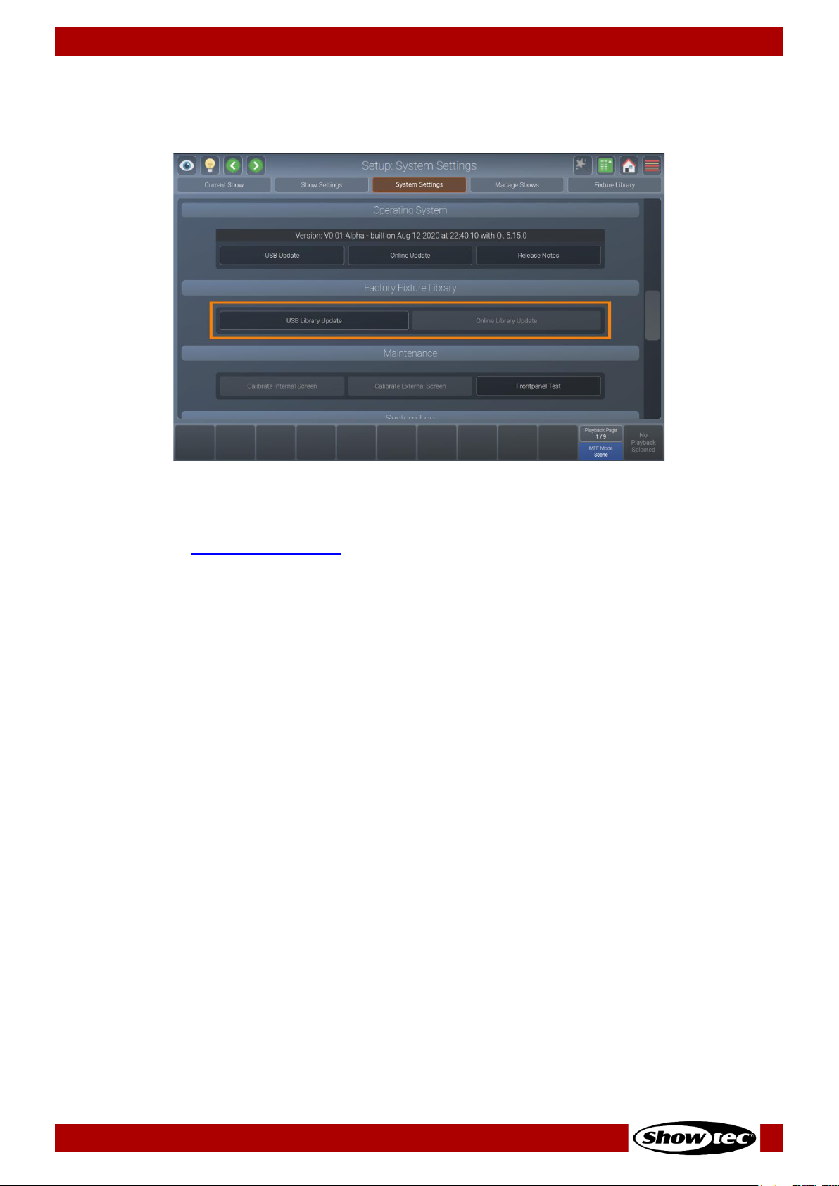
71
Showtec LAMPY Series
Product: 50733 / 50734 / 50735 / 50736
8.5.3.6. Updating the Factory Fixture Library
There are two ways to update the Factory Fixture Library.
Fig. 70: System Settings – Factory Fixture Library
Updating the LAMPY Library Using USB
01) Download the latest software version from the respective product page on the Highlite International
website.
02) Make sure the file extension is .faclib. If the update is delivered in zip format, unzip it first.
03) Copy the .faclib file to the showtec/factory_library folder on a USB flash drive.
04) Open the setup menu.
05) Change to the System Settings view.
06) Scroll down to Factory Fixture Library.
07) Tap USB Library Update.
08) A wizard will walk you through the update process.
Updating the LAMPY Using the Online Update Functionality
01) Make sure the console is connected to the Internet
02) Open the setup menu.
03) Change to the System Settings view.
04) Scroll down to Factory Fixture Library.
05) Tap Online Library Update.
06) A wizard will walk you through the update process.

72
Showtec LAMPY Series
Product: 50733 / 50734 / 50735 / 50736
8.5.3.7. Calibrating the Internal Touchscreen
If the internal touchscreen is misaligned and does not respond properly to your taps, you have to
calibrate it. Follow the instructions below:
01) Open the setup menu.
02) Change to the System Settings view.
03) Scroll down to Maintenance.
04) Tap on Calibrate Internal Screen.
05) A wizard will walk you through the calibration process.
Fig. 71: System Settings – Calibrate Internal Touchscreen

73
Showtec LAMPY Series
Product: 50733 / 50734 / 50735 / 50736
8.5.3.8. Calibrating the External Touchscreen
After connecting a secondary touchscreen, it is usually misaligned and does not respond properly to your
taps. In this case you will have to calibrate it. Follow the instructions below:
01) Open the setup menu.
02) Change to the System Settings view.
03) Scroll down to Maintenance.
04) Tap Calibrate External Screen.
05) A wizard will walk you through the calibration process.
Fig. 72: System Settings – Calibrate External Touchscreen

74
Showtec LAMPY Series
Product: 50733 / 50734 / 50735 / 50736
8.5.3.9. Testing the Front Panel Hardware
Should you ever have the feeling that, buttons, faders or encoders are not responding properly, or that a
LED may be broken, it could be worth inspect the front panel for proper function. Follow the instructions
below:
01) Open the setup menu.
02) Change to the System Settings view.
03) Scroll down to Maintenance.
04) Tap Front panel Test.
05) A dialog box displays all actions you completed, such as encoder and fader movements. You may
also highlight the LEDs on the front panel from this screen.
Fig. 73: System Settings – Front Panel Test Button
Fig. 74: System Settings – Front Panel Test dialog box

75
Showtec LAMPY Series
Product: 50733 / 50734 / 50735 / 50736
8.5.3.10. System Log
The system log can be used to identify errors in the show file, in libraries or other parts of the software. It
contains useful information. To see the system log:
01) Open the setup menu.
02) Change to the System Settings view.
03) Scroll down to System Log.

76
Showtec LAMPY Series
Product: 50733 / 50734 / 50735 / 50736
8.5.4. Manage Shows View
The Manage Shows view may be used to import, export or delete shows. Additionally, it may be used as
a shortcut to open existing shows. It can be accessed in the Setup menu.
Fig. 75: The Manage Shows view
8.5.4.1. Manage Shows - Actions
The Manage Shows - Actions dialog box provides all functionality to work with the Manage Shows view.
The dialog box may be opened by tapping the magic wand button in the Manage Shows view. Many of
the actions are only available if one or multiple shows are selected in the Manage Shows view.
Fig. 76: Manage Shows - Action dialog box

77
Showtec LAMPY Series
Product: 50733 / 50734 / 50735 / 50736
Button
Function
New Show
Is used to start a new show file.
Delete Show
Is used to delete selected shows.
Open Show
Is used to open the selected show.
Import Show(s)
Is used to import shows from a USB flash drive.
Export Show(s)
Is used to export shows to a USB flash drive.
8.5.4.2. Starting a New Show
To start a new show in the Manage Shows view, open the Action dialog box by tapping the magic wand
button.
Select New Show from the action dialog box.
8.5.4.3. Deleting One or Multiple Shows
Should you want to delete one or more shows from the console memory, proceed as follows:
01) Select one or more shows from the Manage Shows view.
02) Open the Action dialog box by tapping the magic wand button.
03) Select Delete Show from the action dialog box.
8.5.4.4. Opening a Show
To open a show from the Manage Shows view, proceed as follows:
01) Select one show from the Manage Shows view list of shows.
02) Open the Action dialog box by tapping the magic wand button.
03) Select Open Show from the action dialog box.
8.5.4.5. Importing One or More Shows from USB
To import one or more shows from a USB flash drive, proceed as follows:
01) Make sure the show files are in the showtec/shows folder on your USB flash drive.
02) Open the Action dialog box from the Manage Shows view by tapping the magic wand button.
03) Select Import Show(s) from the action dialog box.
04) A wizard will guide you through the import process.
8.5.4.6. Exporting One or More Shows to USB
To export one or more shows from the Manage Shows view, proceed as follows:
01) Select one or more shows from the Manage Shows view.
02) Open the Action dialog box by tapping the magic wand button.
03) Select Export Show(s) from the action dialog box.
04) A wizard will guide you through the export process.

78
Showtec LAMPY Series
Product: 50733 / 50734 / 50735 / 50736
8.5.5. Fixture Library View
The Fixture Library view may be used to create, edit, import, export or delete fixtures. It can be accessed
in the setup menu.
Fig. 77: The Fixture Library view
8.5.5.1. Selecting a Fixture Library Category
The Fixture Library view consists of 3 sub selection options which resemble the different library types used
in the console. These are the Factory Library, User Library and Show Library.
In short, the Factory Library is included in the console’s OS and may be updated by USB or internet. It is
read-only. The User Library contains user-created and modified fixtures and is available to all shows on
the console. The Show Library is unique for each show and contains the fixture types used in the show file.
To learn more about the different library types, please see Section 6.3. Fixture Library Basics on page 24.
Fig. 78: The Fixture Library view
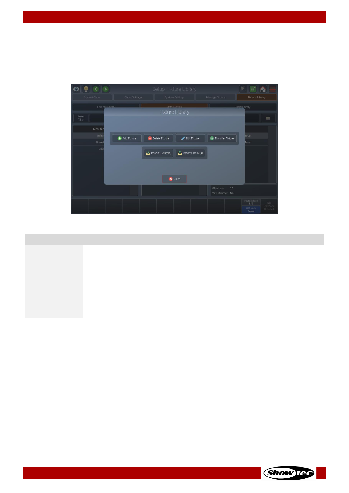
79
Showtec LAMPY Series
Product: 50733 / 50734 / 50735 / 50736
8.5.5.2. Fixture Library Action Dialog Box
The Fixture Library action dialog box provides all functionality to work with the Fixture Library view.
It may be opened by tapping the magic wand button from the Fixture Library view. Many of the actions
are only available if a Fixture Library is selected from the Fixture Library view.
Fig. 79: Fixture Library - Action dialog box
Button
Function
Add Fixture
Is used to create a new fixture library (Only in User / Show Library).
Delete Fixture
Is used to delete selected fixtures(Only in User / Show Library).
Edit Fixture
Is used to edit the selected fixture library (Only in User / Show Library).
Transfer Fixture
Is used to copy the selected fixture library between library categories (Only in User
/ Show Library).
Import Fixture(s)
Is used to import fixtures from a USB flash drive (Only in User / Show Library).
Export Fixture(s)
Is used to export fixtures to a USB flash drive (From all library types).

80
Showtec LAMPY Series
Product: 50733 / 50734 / 50735 / 50736
8.5.5.3. Adding a New Fixture Type
01) To add a new fixture to the User Library or Show Library, first select the library type from the Fixture
Library view in the setup menu.
02) Open the Action dialog box by tapping the magic wand button.
03) Tap Add Fixture.
04) You may now choose to start a fixture from scratch or to use an existing fixture as a template, as
shown in the screenshot below.
Fig. 80: Fixture Library –Create new Fixture Library
Starting a Fixture from Scratch
01) In order to create a fixture from scratch, make sure Create Empty Fixture is selected.
02) Enter the manufacturer’s name, fixture type, short name and mode in the appropriate text fields.
03) Tap Next.
04) Enter the amount of DMX channels this fixture has.
05) Tap Create.
06) The library editor will be shown, allowing you to assign functions to the channels and more.
Starting a Fixture Using an Existing Fixture Type as a Template
01) In order to create a fixture from a template, make sure Use existing Fixture as Template is selected.
02) Enter the manufacturer’s name, fixture type, short name and mode for the new fixture type in the
appropriate text fields.
03) Tap Select Template Fixture. A dialog box is shown to select the fixture type you will use as a base for
the new fixture.
04) Tap Next.
05) The library editor will be shown, allowing you to assign functions to the channels and more.

81
Showtec LAMPY Series
Product: 50733 / 50734 / 50735 / 50736
8.5.5.4. Deleting a Fixture Type
01) To delete a fixture type, select the Fixture Library view in the setup menu.
02) Select the fixture type you want to delete.
03) Open the Fixture Library action dialog box using the magic wand button.
04) Tap Delete Fixture.
05) Please be absolutely sure, before you tap Delete.
8.5.5.5. Editing / Modifying a Fixture Type
01) To edit or modify a fixture type, select the Fixture Library view in the setup menu.
02) Select the fixture type you want to edit from the User Library or Show Library. Please note that the
factory library is read-only. If you want to edit a fixture from the factory library, you first need to
transfer it to the user library. See 8.5.5.6 Transferring (Copying) a Fixture Type between Libraries on
page 81 for more details.
03) Open the Fixture Library action dialog box using the magic wand button.
04) Tap Edit Fixture.
05) The Library Editor will be shown, allowing you to assign functions to the channels, etc. Note: If you edit
a fixture type in the User Library and are using the same fixture type in your show, changes made in
the User Library are not automatically carried over to the fixture type in the Show Library.
8.5.5.6. Transferring (Copying) a Fixture Type between Libraries
To transfer fixtures between different library types, follow the steps below:
01) To transfer a fixture type, select the Fixture Library view in the setup menu.
02) Select the fixture type you want to transfer.
03) Open the Fixture Library action dialog box using the magic wand button.
04) Tap Transfer Fixture.
05) A dialog box will be shown asking you for the destination library type.

82
Showtec LAMPY Series
Product: 50733 / 50734 / 50735 / 50736
8.5.5.7. Importing Fixture Types from USB
01) To import a fixture library from a USB flash drive, select the Fixture Library view in the setup menu.
02) Select the library type (User Library or Show Library).
03) Make sure the fixture library file is in the showtec/library folder on your USB flash drive.
04) Open the Fixture Library action dialog box using the magic wand button.
05) Tap Import Fixture(s).
06) A dialog box will be shown, asking you for the library file on your USB flash drive and for the import
mode.
07) Select either Merge (which will add the Fixtures on the USB flash drive), Replace Manufacturers or
Replace Complete Library at the top of the dialog box.
08) Tap Import.
Fig. 81: Import Fixture Library – Select Library File
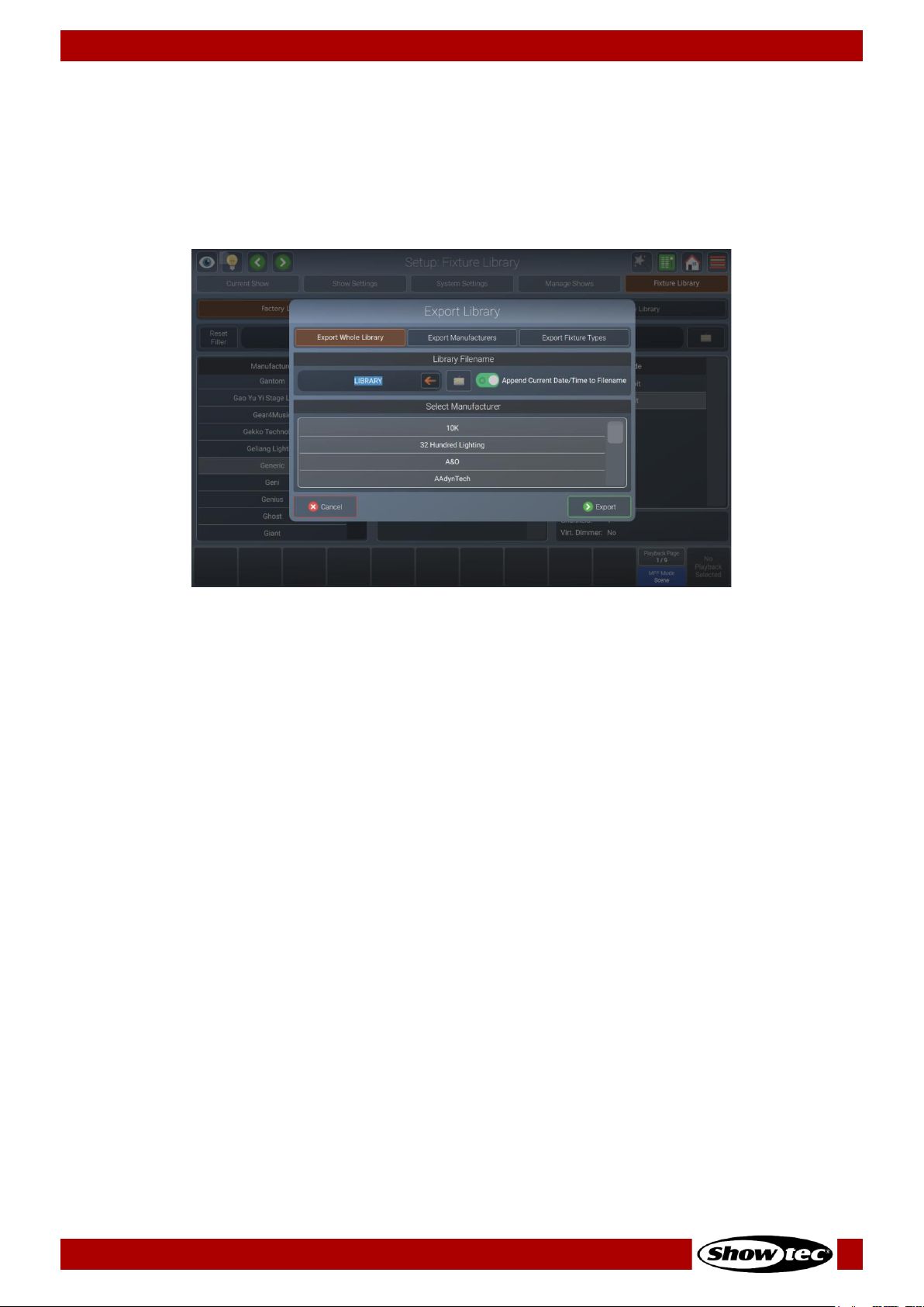
83
Showtec LAMPY Series
Product: 50733 / 50734 / 50735 / 50736
8.5.5.8. Exporting Fixture Types to USB
01) To export a fixture library to a USB flash drive, select the Fixture Library view in the setup menu.
02) Select the library type (Factory Library, User Library or Show Library).
03) Open the fixture library action dialog box using the magic wand button.
04) Tap on Export Fixture(s).
05) A wizard will guide you through the process and you will be able to select what to export.
06) Tap on Export.
Fig. 82: Export Fixture Library – Specify Fixtures
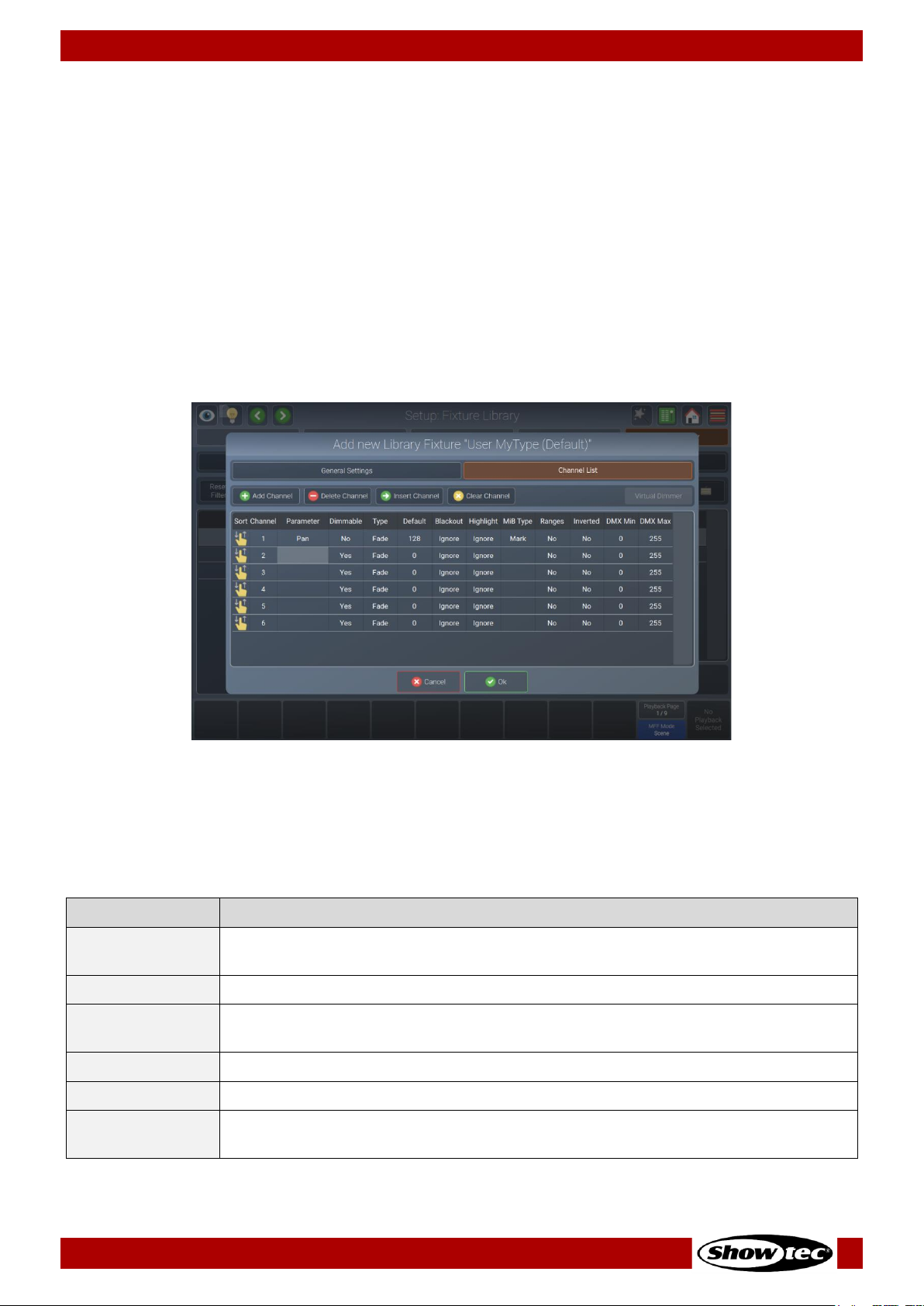
84
Showtec LAMPY Series
Product: 50733 / 50734 / 50735 / 50736
8.5.5.9. The Library Editor
This section explains the library editor which is used throughout the library creation or edit process.
The library editor consists of two different pages. One contains the general settings of a fixture (like type,
short type, mode and pan / tilt range – adjustable using the encoders). The other one contains the
attribute mapping (Channel List).
The Channel List page will always be displayed first. To switch to the general settings, tap the General
Settings view ab shown at the top of the dialog box.
Channel List
In Channel List mode, the top row of buttons is used to append, delete, insert new channels, or to clear
the selected channel mapping. Additionally, it may be used to add a virtual dimmer to the fixture, if
additional color mixing attributes (RGB, etc.) are present.
Fig. 83: Edit Fixture Library – Channel List
When the Channel List is selected, a table used to alter the mapping of the DMX Channels to Attributes is
shown.
Select the cell with the value you want to change. Double tap the cell and enter the desired value in the
pop-up.
Column
Function
Sort
Is used to re-arrange the channel layout, for example to change channel 1 to
channel 6, without losing any settings.
Channel
Is used to indicate the channel number.
Parameter
Is used to select the attribute of this channel. For more information see the section
about parameter selection on page 84.
Dimmable
Defines if this channel should react to dimmer faders or the grand master fader.
Type
Defines if this channel can fade or snap to a value (useful for color channels).
Default
Defines the default value that will be output to a fixture, if no playback containing
this attribute is active.
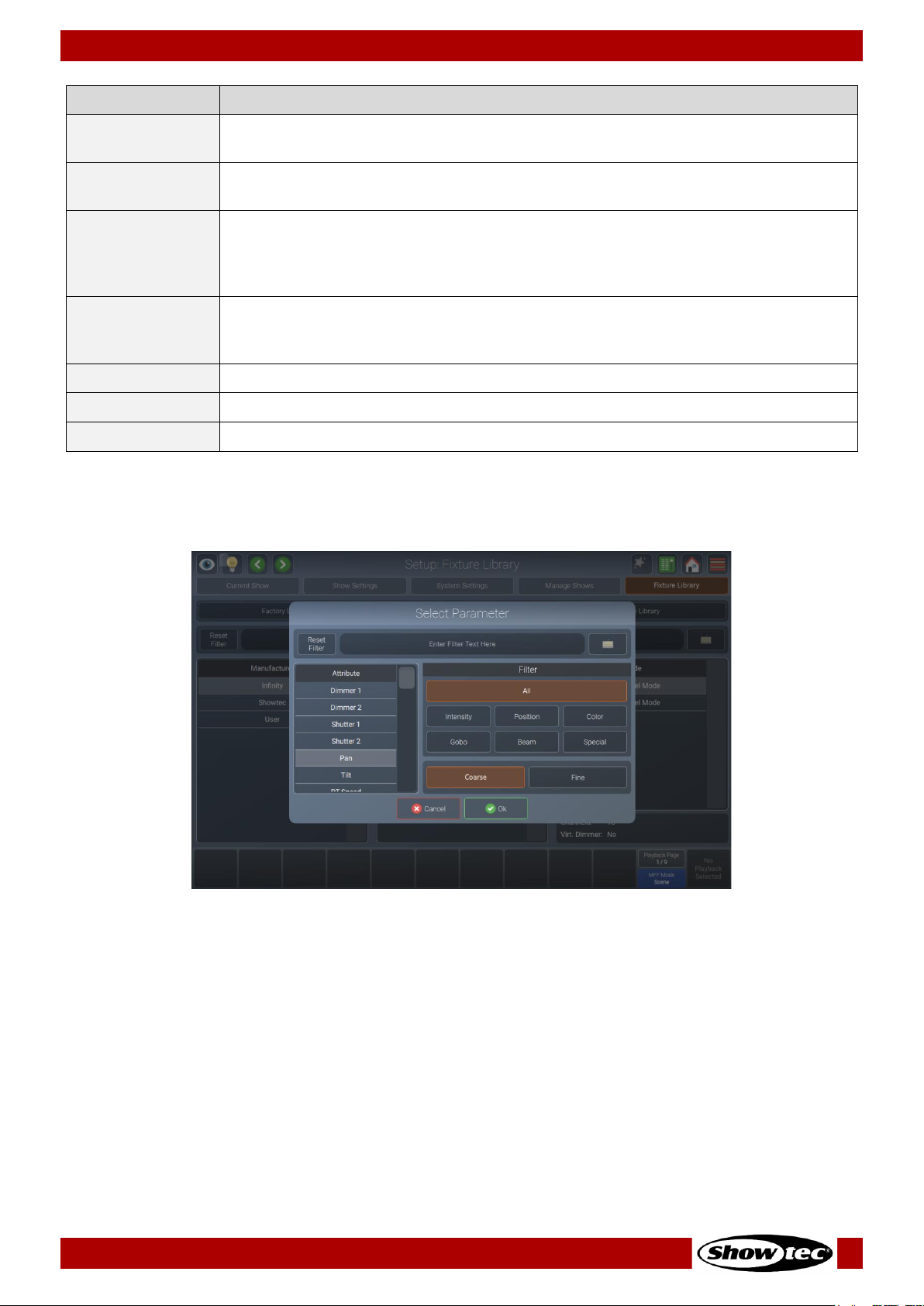
85
Showtec LAMPY Series
Product: 50733 / 50734 / 50735 / 50736
Column
Function
Blackout
Defines the value that will be output when the grand master fader is at 0 % or
when blackout is active.
Highlight
Defines which value will be output when the Highlight function is active in the
programmer. Usually this would be 100 % brightness, white, etc.
MiB Type
Defines how a fixture attribute behaves with the “Move in Black” functionality. An
empty cell means this attribute will not react to move in black. Mark means this
attribute will fade to the new value. Mark Zero means this attribute will snap to the
new value.
Ranges
Defines the little gobo icons, color indication in different views, or the names of a
particular part of this attributes channel (for example: lamp on, lamp off, etc.).
More info can be found in the “Edit Ranges” section on page 86.
Inverted
Inverts the DMX output for this channel.
DMX Min
May be used to hard limit the minimum value of this DMX channel.
DMX Max
May be used to hard limit the maximum value of this DMX channel.
Select Parameter Menu
Double-tap in a parameter cell to select the parameter mapped to a channel.
Fig. 84: Edit Fixture Library – Select Parameter
You will see a list of available parameters on the left-hand side. This list may be filtered by entering the
search string into the filter text field at the top of the screen. You may further define the search by filtering
by attribute groups.
The Coarse and Fine buttons may be used to toggle between the assignment of a coarse or a fine
channel.
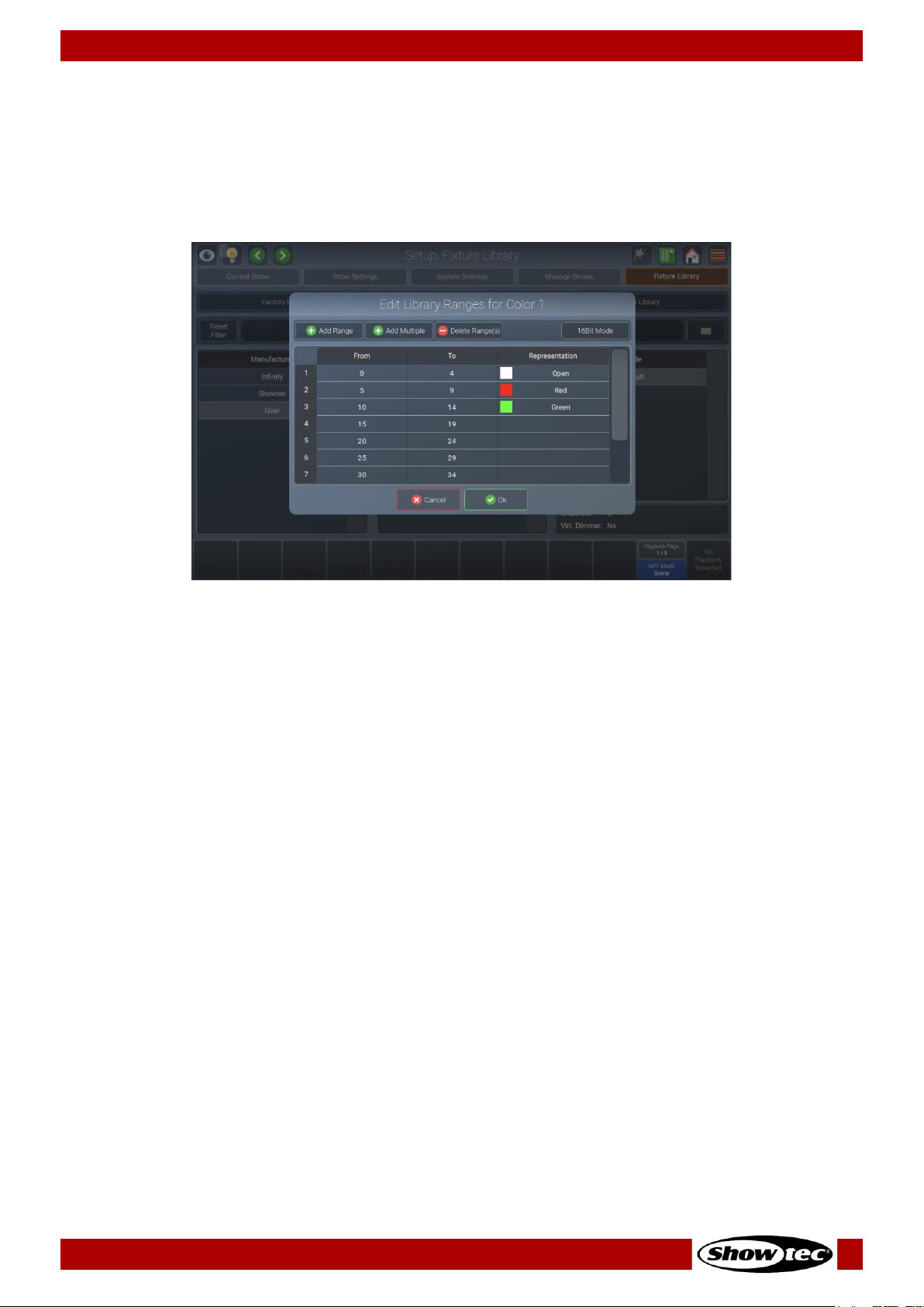
86
Showtec LAMPY Series
Product: 50733 / 50734 / 50735 / 50736
Edit Ranges Menu
The Edit Ranges menu is used to specify how channel functions are mapped to the corresponding DMX
values, enabling you to show the name or even icons for a specific range of values in the programmer
and the Select Range pop-up that opens when you press the encoder.
It is opened by selecting the double tapping in the Ranges cell for the appropriate parameter.
Fig. 85: Edit Fixture Library – Range Editor
To add a single range to the list, tap the Add Range button. A new screen will be shown allowing you to
specify information about this range.
You may also add multiple ranges to the list by tapping the Add Multiple button. A new screen will be
shown allowing you to specify information about this range.
To delete one or multiple entries from the list, select it/them and tap on the Delete Range(s) button.
To edit an already existing range, double-tap on an option in the table.
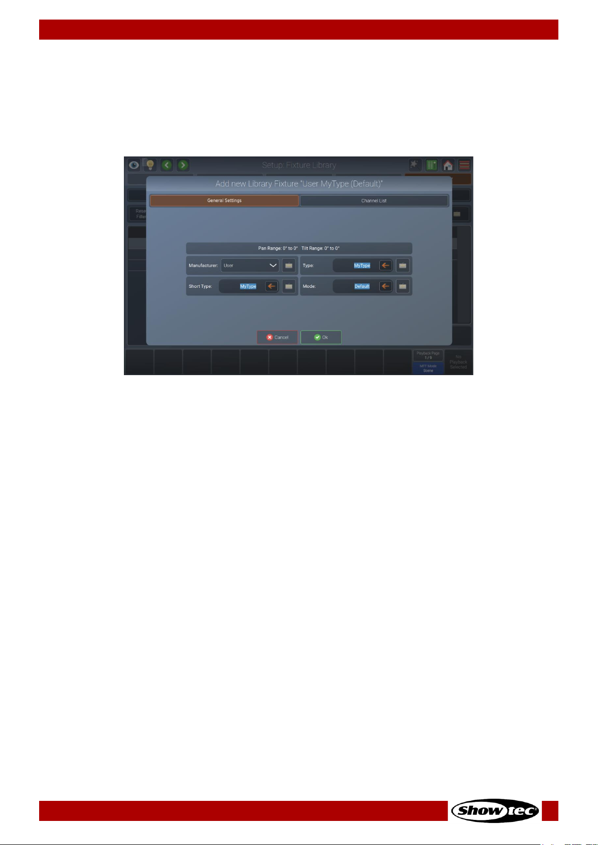
87
Showtec LAMPY Series
Product: 50733 / 50734 / 50735 / 50736
General Settings
In general setup mode you may set the manufacturer’s name, fixture type, short name and mode values
by typing them in one of the text fields when creating a new fixture. Existing fixtures cannot be renamed.
Pan & tilt range(in degrees) may be set using the encoders if the fixture has pan / tilt attributes in the
channel list.
Fig. 86: Edit Fixture Library – General Settings

88
Showtec LAMPY Series
Product: 50733 / 50734 / 50735 / 50736
8.6. Using the Home Screen
The home screen is the central place of the console where all the programming is done.
You may open the home screen by tapping the home button in the top toolbar or by pressing [Home]
key on the console’s front panel. Repeatedly pressing this button allows you to toggle through the
different views in the home screen.
Tap the corresponding buttons (Fixtures, Groups, Presets, Values (the Programmer) and Effects) to
change their settings at the top of the screen.
Fig. 87: Home Screen – Fixtures View
Whenever the home screen is open, the encoders control the attributes of the selected fixtures. To switch
between the different attributes and attribute groups, press the [Int], [Pos], [Color], [Gobo], [Beam] or
[Spec] keys on the front panel or use the drop-down menu at the top right of the home screen.

89
Showtec LAMPY Series
Product: 50733 / 50734 / 50735 / 50736
8.6.1. The Fixtures View
The fixtures view in the home screen allow you to select fixtures and change their settings according to
your preference. For example to make them resemble the physical layout – or just a very simple grid
layout.
If you have a 2-universe console or a 1-universe console with the LAMPY DNGL attached, you have 2
different and independent fixture sheets to lay out your fixtures. The different sheets may be selected
using the sheet buttons at the top right of this view.
Fig. 88: Home Screen – Fixtures View – Select Sheet (With LAMPY DNGL only)
8.6.1.1. Navigating the Fixtures View
You may navigate around the fixture using the buttons and sliders on the right side of the fixture view:
Fig. 89: Home Screen – Fixtures View – Navigation Controls
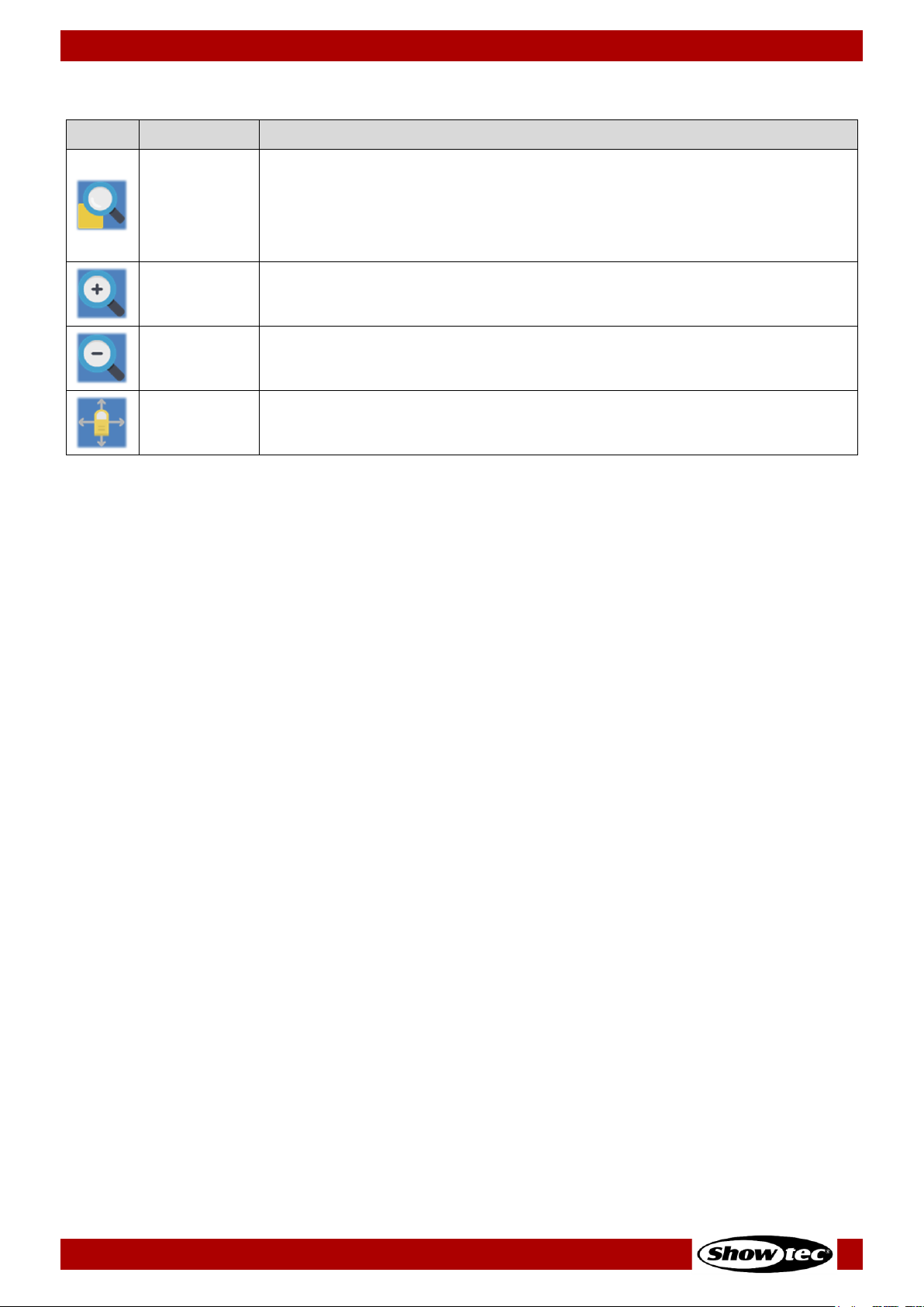
90
Showtec LAMPY Series
Product: 50733 / 50734 / 50735 / 50736
The buttons in the navigation controls section have the following functions:
Name
Action
Zoom Fit
If no fixtures are selected, Zoom Fit will zoom and move the viewport showing
the full extent of the fixture view.
If fixtures are selected, it will zoom and center the view on the selected
fixtures.
Zoom +
Increases the zoom level, so items get bigger.
Zoom -
Decreases the zoom level, so items get smaller.
Move View
Changes into the “Move Viewport” mode, which allows you to move the
view around.

91
Showtec LAMPY Series
Product: 50733 / 50734 / 50735 / 50736
8.6.1.2. The Fixture Item
The fixture Item itself provides several layers of feedback to you:
Item
Meaning
This fixture is not selected, dimmer is at 0 % and no values are in the programmer.
This fixture is selected (orange background), is outputting 100 % dimmer, yellow color
and a gobo. Pan / tilt are centered. The red bar at the bottom indicates that this
fixture has set values in the programmer (Values view).
8.6.1.3. Fixture Actions Dialog Box (Magic Wand Button)
The Fixture Actions dialog box provides all functionality to work with the fixture view. It may be opened by
tapping the magic wand button from the fixture view. Many of the actions are only available if one or
multiple items are selected in the view.
Fig. 90: Fixture View - Action dialog box

92
Showtec LAMPY Series
Product: 50733 / 50734 / 50735 / 50736
Button
Function
Add Label
Used to add a label to the fixture view.
Add Groups
Used to add a group Item to the fixture view.
Add Fixtures
Used to add fixtures to the fixture view. Only available for fixtures that have not
been added to the view.
Edit Label
Used to set a labels text and color as well as size.
Move Items
Used to move single items in free-hand mode.
Delete Items
Used to delete items from the fixture view.
Arrange Linear
Used to automatically arrange multiple elements along a line.
Arrange Arc
Used to automatically arrange multiple items along an arc.
Arrange Grid
Used to automatically arrange multiple items in a grid.
Arrange Circular
Used to automatically arrange multiple items in a circle.
Arrange Chessboard
Used to automatically arrange multiple items like a chessboard.

93
Showtec LAMPY Series
Product: 50733 / 50734 / 50735 / 50736
8.6.1.4. Adding Elements to the Fixtures View
If you want to add Items to the fixture view, tap on the magic wand button. The dialog box will open.
Fig. 91: Fixture View - Action dialog box – Add Items
Adding Labels
Labels may be used as a visual indication or quick selection of different items. To add a label, please
proceed as follows:
01) Open the action dialog box by tapping the magic wand button.
02) Tap the Label in the Add… group box.
03) Tap the screen and with your finger draw a rectangle on the screen, where the label should be.
04) Now you have the chance to make some corrections. You may move the label by tapping and
sliding, and you may resize it using the handle in the lower right corner of the new label.
05) Tap Apply in the lower right corner.
06) A dialog box will be opened asking you for the label’s text and color.
07) Tap Ok.
Adding Groups
To add a group to the fixture view, please proceed as follows:
01) Open the action dialog box by tapping the magic wand button.
02) Tap Groups in the Add… group box.
03) Select the groups you want to add from the dialog box that was just opened. Tap Ok when done.
04) Move the added groups where they should go. Do so by tapping and moving the group.
05) Tap Apply in the lower right corner.

94
Showtec LAMPY Series
Product: 50733 / 50734 / 50735 / 50736
Adding Fixtures
To add a fixture to the fixture view, please proceed as follows:
01) Open the action dialog box by tapping the magic wand button.
02) Tap Fixtures in the Add… group box.
03) Select the fixtures you want to add from the dialog box that was just opened. Tap Ok when done.
04) Select one of the arrange modes to place the fixtures in the view. For more information about the
different arrange modes, please see section 8.6.1.7. Arranging Existing Elements on page 96.
05) Tap Apply at the lower right corner when done.
8.6.1.5. Selecting and De-selecting Fixtures
You may select / deselect objects in the Fixtures screen by tapping them, or by “drawing” a selection
rectangle, similar to keeping your mouse cursor pressed while moving the mouse to select multiple items
on your computer’s desktop. You may also select items that are inside a label by tapping on the label.
Whenever fixtures are selected, a deselect button is shown at the bottom right part of the screen.
8.6.1.6. Editing Existing Elements
If you want to edit Items in the fixture view, tap the magic wand button. The action dialog box will be
opened.
Fig. 92: Fixture View - Action dialog box – Edit Items
Editing Labels
To change a label’s appearance or size, please proceed as follows:
01) Open the action dialog box by tapping on the magic wand button.
02) Tap Edit Label.
03) Select the label you want to edit in the fixture view.
04) You may now move or resize the label.
05) Tap Apply in the lower right corner.
06) A dialog box that allows you to set the text and color of the label is opened.
07) Tap Ok when done.
Note: It is not allowed to add the same fixture to a sheet twice. If fixtures in the showfile are already in the
sheet, the Add Fixtures button will be greyed out.

95
Showtec LAMPY Series
Product: 50733 / 50734 / 50735 / 50736
Moving Items
To move items in the fixture view in free-hand mode, please proceed as follows:
01) Open the action dialog box by tapping the magic wand button.
02) Tap Move Items.
03) Select and move the items by drag and drop.
04) Tap Apply in the lower right corner.
Deleting Items
To delete an item from the fixture view, please proceed as follows:
01) Open the action dialog box by tapping the magic wand button.
02) Tap Delete Items.
03) Select the Items you want to delete in the fixture.
04) Tap Apply in the lower right corner.
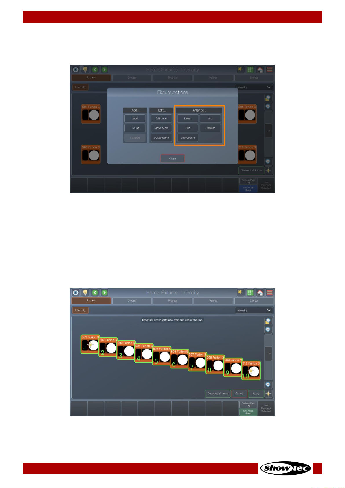
96
Showtec LAMPY Series
Product: 50733 / 50734 / 50735 / 50736
8.6.1.7. Arranging Existing Elements
If you want to arrange items in the fixture view using one of the available arrange modes, tap the magic
wand button. The action dialog box will be opened.
Fig. 93: Fixture View - Action dialog box – Arrange Items
Arrange Linear
Arrange Linear will rearrange all items in a line, asking you to specify the first and the last point of the line
using drag handles. To arrange items like this, please proceed as follows:
01) Open the action dialog box by tapping the Magic Wand button.
02) Tap Linear in the Arrange… group box.
03) Select the items you want to arrange in the fixture view and tap Apply.
04) Adjust the start point and end point of the arrangement by using the drag handles.
05) Tap Apply at the lower right corner.
Fig. 94: Fixture View – Arrange Linear
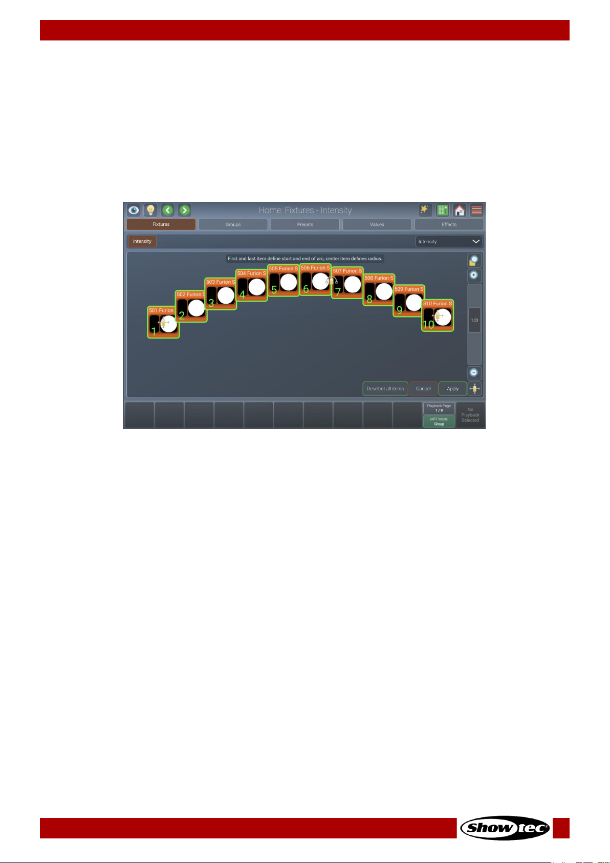
97
Showtec LAMPY Series
Product: 50733 / 50734 / 50735 / 50736
Arrange Arc
Arrange Arc will rearrange all items in an arc, asking you to specify the start point, radius and endpoint
using drag handles.
01) Open the action dialog box by tapping the Magic Wand button.
02) Tap Arc in the Arrange… group box.
03) Select the items you want to arrange in the fixture view and tap Apply.
04) Adjust the start point and end point as well as the radius of the arrangement by using the drag
handles.
05) Tap Apply at the lower right corner.
Fig. 95: Fixture View – Arrange Arc
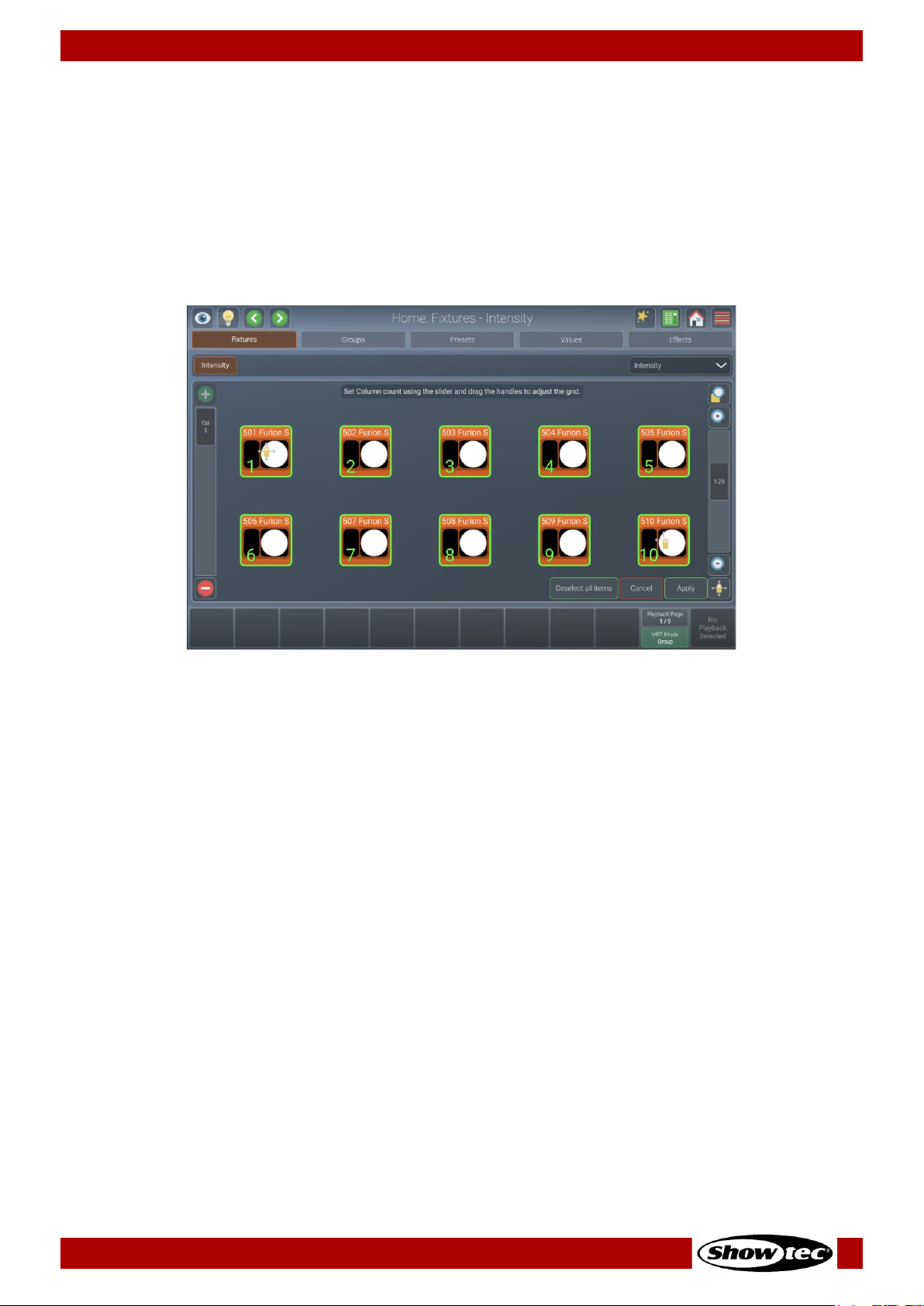
98
Showtec LAMPY Series
Product: 50733 / 50734 / 50735 / 50736
Arrange Grid
Arrange Grid will rearrange all items in a grid, asking you to specify the position and the size of the grid
using drag handles. The slider on the left side specifies the number of columns.
01) Open the action dialog box by tapping the magic wand button.
02) Tap Grid in the Arrange… group box.
03) Select the items you want to arrange in the fixture view and tap Apply.
04) Adjust the start point and end point of the arrangement by using the drag handles.
05) Adjust the column count using the slider on the left.
06) Tap Apply at the lower right corner.
Fig. 96: Fixture View – Arrange Grid
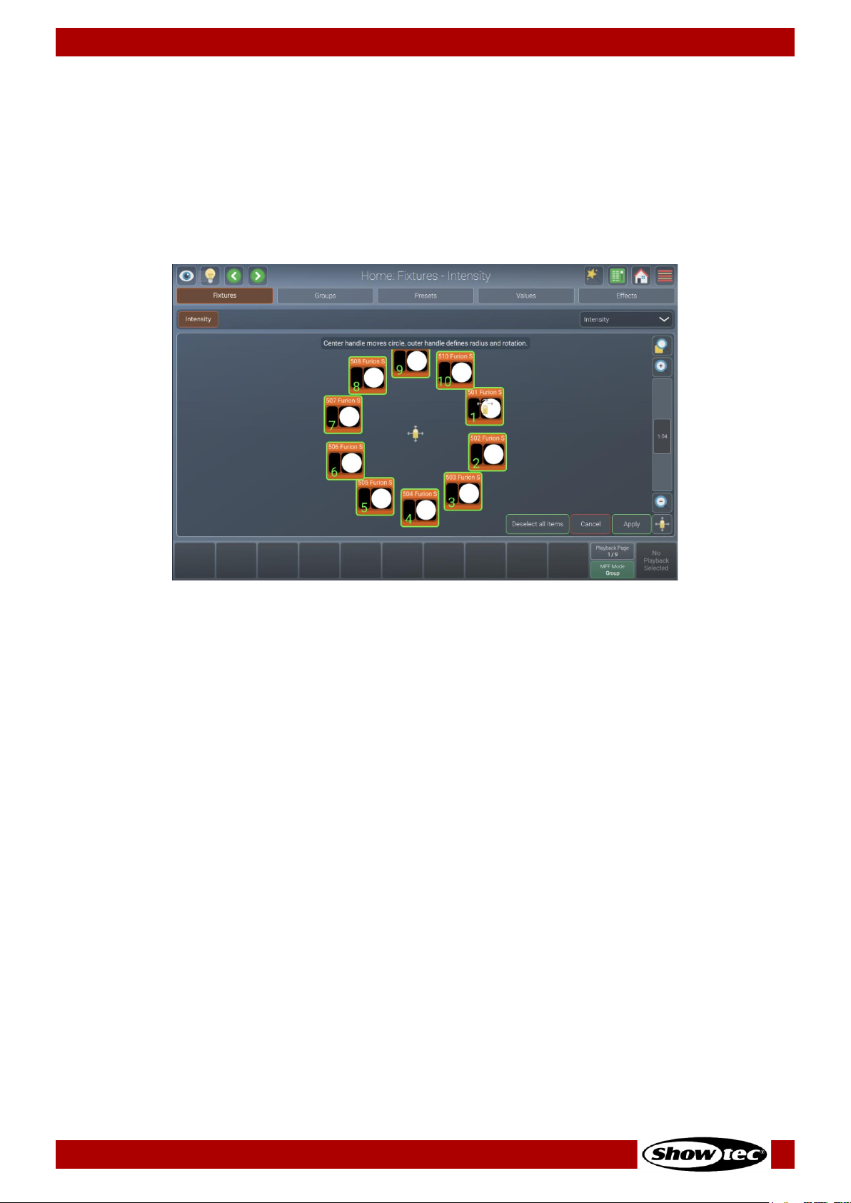
99
Showtec LAMPY Series
Product: 50733 / 50734 / 50735 / 50736
Arrange Circular
Arrange Circular will rearrange all items in a circle, asking you to specify the center point and the size /
rotation using drag handles.
01) Open the action dialog box by tapping the magic wand button.
02) Tap Circular in the Arrange… group box.
03) Select the items you want to arrange in the fixture view and tap Apply.
04) Adjust the start point and radius / rotation of the arrangement by using the drag handles.
05) Tap Apply at the lower right corner.
Fig. 97: Fixture View – Arrange Circular
 Loading...