

Page 1
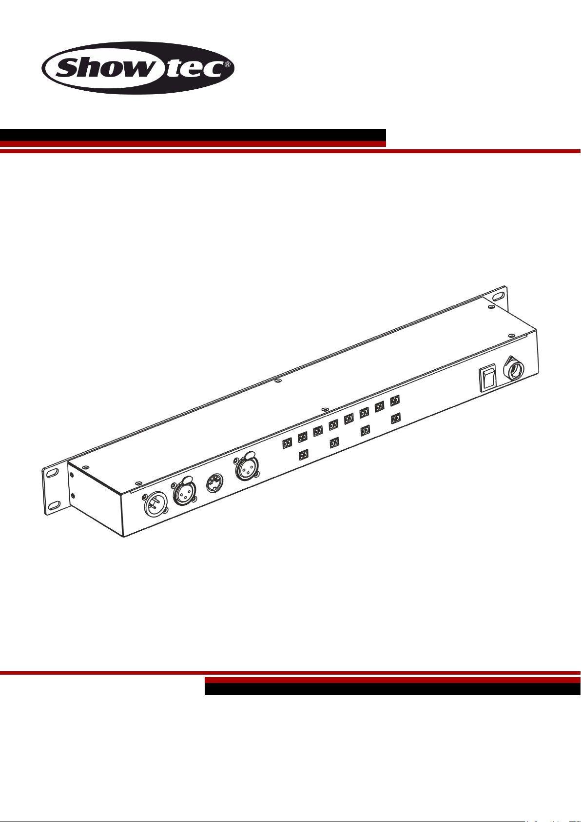
DR Pro Rack V1
Highlite International B.V. – Vestastraat 2 – 6468 EX – Kerkrade – the Netherlands
Ordercode: 50821
MANUAL
ENGLISH
Page 2

Ordercode: 50821
DR Pro Rack
Table of contents
Warning ............................................................................................................................................................................... 2
Safety Instructions ......................................................................................................................................................... 2
Operating Determinations .......................................................................................................................................... 4
Rigging ............................................................................................................................................................................ 4
Connection with the mains......................................................................................................................................... 4
Return Procedure .......................................................................................................................................................... 5
Claims .............................................................................................................................................................................. 5
Description of the device ................................................................................................................................................. 6
Frontside.......................................................................................................................................................................... 6
Backside ......................................................................................................................................................................... 7
Installation ........................................................................................................................................................................... 7
Set Up and Operation ....................................................................................................................................................... 8
Control Modes ............................................................................................................................................................... 8
Data Cabling ................................................................................................................................................................. 8
Start-up............................................................................................................................................................................ 9
1. Record DMX..........................................................................................................................................................10
1.1 Recording scenes ..............................................................................................................................................10
1.2 Recording shows................................................................................................................................................11
1.3 Adding chases ...................................................................................................................................................12
1.4 Editing chases ....................................................................................................................................................13
1.5 Deleting scenes .................................................................................................................................................14
1.6 Deleting shows ...................................................................................................................................................15
1.7 Deleting chases .................................................................................................................................................16
2. Trigger Event .........................................................................................................................................................17
2.1. Time Event ..........................................................................................................................................................17
2.1.1 Editing time events .........................................................................................................................................19
2.1.2 Deleting time events ......................................................................................................................................20
2.2. SMPTE/MTC Event .............................................................................................................................................21
2.2.1 Adding SMPTE/MTC events ..........................................................................................................................22
2.2.2 Editing SMPTE/MTC events ............................................................................................................................23
2.2.3 Deleting SMPTE/MTC events .........................................................................................................................23
2.3. DMX trigger ........................................................................................................................................................24
3. Assign Memory .....................................................................................................................................................25
4. Set Date/Time .......................................................................................................................................................26
5. Set Password .........................................................................................................................................................27
6. Data backup ........................................................................................................................................................28
Control Panel ...............................................................................................................................................................30
Control Mode ..............................................................................................................................................................30
DMX Addressing ..........................................................................................................................................................30
Main Menu Options ....................................................................................................................................................31
1. Manual Control ....................................................................................................................................................31
2. Timer Event ............................................................................................................................................................31
3. DMX Monitor .........................................................................................................................................................32
4. SMPTE/MIDI Trigger ..............................................................................................................................................32
5. DMX Trigger ...........................................................................................................................................................32
6. Unit Version ...........................................................................................................................................................33
7. SET & MODIFY ........................................................................................................................................................33
DMX Channels .............................................................................................................................................................33
3 channels .................................................................................................................................................................33
Maintenance ....................................................................................................................................................................34
Troubleshooting ...............................................................................................................................................................34
No Light .........................................................................................................................................................................34
No Response to DMX..................................................................................................................................................34
Product Specification .....................................................................................................................................................36
1
Page 3
Ordercode: 50821
DR Pro Rack
Your shipment includes:
● Showtec DR Pro Rack
● DC power adapter 9V, 500 mA (1,5m)
● USB cable (0,9m)
● User manual
Warning
Unpacking Instructions
Immediately upon receiving this product, carefully unpack the carton and check the contents to ensure
that all parts are present, and have been received in good condition. Notify the dealer immediately and
retain packing material for inspection if any parts appear damaged from shipping or the carton itself
shows signs of mishandling. Save the carton and all packing materials. In the event that a fixture must be
returned to the factory, it is important that the fixture be returned in the original factory box and packing.
Safety Instructions
Every person involved with the installation, operation and maintenance of this device has to:
● be qualified
● follow the instructions of this manual
Before your initial start-up, please make sure that there is no damage caused by transportation.
Should there be any, consult your dealer and do not use the device.
To maintain perfect condition and to ensure a safe operation, it is absolutely necessary for the user to
follow the safety instructions and warning notes written in this manual.
Please consider that damages caused by manual modifications to the device are not subject to
warranty.
This device contains no user-serviceable parts. Refer servicing to qualified technicians only.
2
Page 4

Ordercode: 50821
DR Pro Rack
IMPORTANT:
The manufacturer will not accept liability for any resulting damages caused by the non-observance of
this manual or any unauthorized modification to the device.
Never let the power cord come into contact with other cables! Handle the power cord and all
connections with the mains with particular caution!
Never remove warning or informative labels from the unit.
Never use anything to cover the ground contact.
Never leave any cables lying around.
Do not connect this device to a dimmerpack.
Do not switch the device on and off in short intervals, as this would reduce the device’s life.
Do not touch the device’s housing bare-handed during its operation. Allow the fixture to cool for at
least 5 minutes before handling.
Do not shake the device. Avoid brute force when installing or operating the device.
Only use device indoor, avoid contact with water or other liquids.
Only operate the fixture after having checked that the housing is firmly closed and all screws are
tightly fastened.
Only operate the device after having familiarized with its functions.
Avoid flames and do not put close to flammable liquids or gases.
Always keep case closed while operating.
Always allow free air space of at least 50 cm around the unit for ventilation.
Always disconnect power from the mains, when device is not used or before cleaning! Only handle
the power cord by the plug. Never pull out the plug by tugging the power cord.
Make sure that the device is not exposed to extreme heat, moisture or dust.
Make sure that the available voltage is not higher than stated on the rear panel.
Make sure that the power cord is never crimped or damaged. Check the device and the power
cord from time to time.
If the lens is obviously damaged, it has to be replaced, so that its functions are not impaired due to
cracks or deep scratches.
If device is dropped or struck, disconnect mains power supply immediately. Have a qualified
engineer inspect for safety before operating.
If the device has been exposed to drastic temperature fluctuation (e.g. after transportation), do not
switch it on immediately. The arising condensation water might damage your device. Leave the
device switched off until it has reached room temperature.
If your Showtec device fails to work properly, discontinue use immediately. Pack the unit securely
(preferably in the original packing material), and return it to your Showtec dealer for service.
For adult use only. Device must be installed out of the reach of children. Never leave the unit running
unattended.
Never attempt to bypass the thermostatic switch or fuses.
The user is responsible for correct positioning and operating of the DR Pro Rack. The manufacturer will
not accept liability for damages caused by the misuse or incorrect installation of this device.
This device falls under protection class I. Therefore it is essential to connect the yellow/green
conductor to earth.
During the initial start-up some smoke or smell may arise. This is a normal process and does not
necessarily mean that the device is defective.
Repairs, servicing and electric connection must be carried out by a qualified technician.
WARRANTY: Till one year after date of purchase.
3
Page 5
Ordercode: 50821
DR Pro Rack
International
EU Cable
UK Cable
US Cable
Pin
L
BROWN
RED
YELLOW/COPPER
PHASE
N
BLUE
BLACK
SILVER
NULL
YELLOW/GREEN
GREEN
GREEN
EARTH
Operating Determinations
● This device is not designed for permanent operation. Consistent operation breaks will ensure that the
device will serve you for a long time without defects.
● The maximum ambient temperature ta = 40°C must never be exceeded.
● The relative humidity must not exceed 50 % with an ambient temperature of 40° C.
● If this device is operated in any other way, than the one described in this manual, the product may
suffer damages and the warranty becomes void.
● Any other operation may lead to dangers like short-circuit, burns, electric shock, crash etc.
You endanger your own safety and the safety of others!
Rigging
Please follow the European and national guidelines concerning rigging, trussing and all
other safety issues.
Do not attempt the installation yourself !
Always let the installation be carried out by an authorized dealer !
The DR Pro Rack can be placed on a flat stage floor or mounted to a 19-inch mounting rack.
Improper installation can cause serious damage to people and property !
Connection with the mains
Connect the device to the mains with the power-plug.
Always pay attention, that the right color cable is connected to the right place.
Make sure that the device is always connected properly to the earth!
4
Page 6
Ordercode: 50821
DR Pro Rack
Return Procedure
Returned merchandise must be sent prepaid and in the original packing, call tags will not be issued.
Package must be clearly labeled with a Return Authorization Number (RMA number). Products returned
without an RMA number will be refused. Highlite will not accept the returned goods or any responsibility.
Call Highlite 0031-455667723 or mail aftersales@highlite.nl and request an RMA prior to shipping the fixture.
Be prepared to provide the model number, serial number and a brief description of the cause for the
return. Be sure to properly pack fixture, any shipping damage resulting from inadequate packaging is the
customer’s responsibility. Highlite reserves the right to use its own discretion to repair or replace
product(s). As a suggestion, proper UPS packing or double-boxing is always a safe method to use.
Note: If you are given an RMA number, please include the following information on a piece of paper
inside the box:
01) Your name
02) Your address
03) Your phone number
04) A brief description of the symptoms
Claims
The client has the obligation to check the delivered goods immediately upon delivery for any shortcomings and/or visible defects, or perform this check after our announcement that the goods are at their
disposal. Damage incurred in shipping is the responsibility of the shipper; therefore the damage must be
reported to the carrier upon receipt of merchandise.
It is the customer's responsibility to notify and submit claims with the shipper in the event that a fixture is
damaged due to shipping. Transportation damage has to be reported to us within one day after receipt
of the delivery.
Any return shipment has to be made post-paid at all times. Return shipments must be accompanied with
a letter defining the reason for return shipment. Non-prepaid return shipments will be refused, unless
otherwise agreed in writing.
Complaints against us must be made known in writing or by fax within 10 working days after receipt of the
invoice. After this period complaints will not be handled anymore.
Complaints will only then be considered if the client has so far complied with all parts of the agreement,
regardless of the agreement of which the obligation is resulting.
5
Page 7
Ordercode: 50821
DR Pro Rack
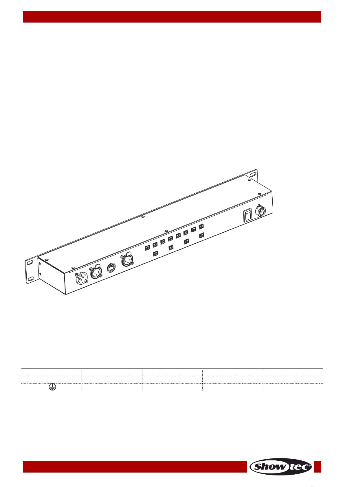
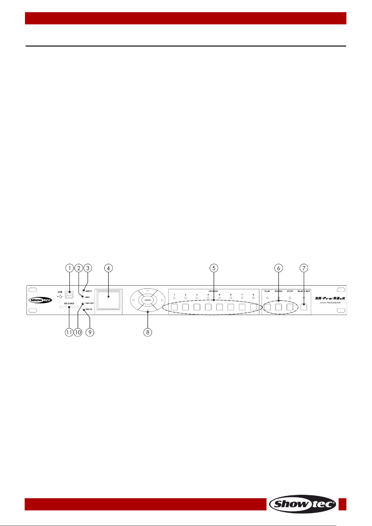
Fig. 01
Description of the device
Features
The DR Pro Rack is a useful tool to store DMX values of complete scenes, chases or shows. The total
recording time is 5 hours, shared over the 8 memory channels. The basic functions are easy to control
with the direct playback buttons on the front panel, which makes it ideal for non-technical users.
The unit can be locked with a password.
Input voltage: 100-240V, 60/50 Hz
Power supply: 9~12V DC power adapter , 500mA
Power consumption: 5W
Data signal: DMX/MIDI/SMPTE
Control modes: DMX Recording Mode, Time Trigger, SMPTE/MIDI Trigger, DMX Trigger, DMX Monitor
Internal memory: 2G
External memory: <8G
SD card and USB support
Connections: 3-pin XLR IN & OUT, SD card port, 5-pin MIDI IN
SMPTE connector: 3-pin XLR IN
8 memory channels for scenes, chases and shows
5-hour long recording time
Control protocol: DMX-512 or DMX-1000K
LCD display for easy setup
IP rating: IP20
Dimensions: 482 x 78 x 44 mm (LxWxH); 19 inch x 1HE (LxH)
Weight: 1,2 kg
Frontside
01) USB B connector
This connector can be used for connecting the DR Pro Rack to your PC, in order to import/export
data. The DR Pro Rack will appear as an external drive on your PC. Please note, that the file names
which are to be recognized by the DR Pro Rack, should not consist of more than 8 characters.
02) MIDI LED indicator
This indicator will light up when MIDI signal is being received in the SMPTE/MIDI Trigger Mode.
03) SMPTE LED indicator
This indicator will light up when SMPTE signal is being received in the SMPTE/MIDI Trigger Mode.
04) LCD display
05) Memory buttons 1-8
Press the buttons to call up the desired memory channel in the Manual Mode.
06) PLAY/PAUSE/STOP buttons
Press the buttons to play, pause or stop your recorded data.
07) BLACKOUT button
Press the button to control DMX output in the Manual Mode.
08) LEFT/RIGHT/UP/DOWN/ENTER buttons
Press the buttons to toggle between the available options.
6
Page 8
Ordercode: 50821
DR Pro Rack
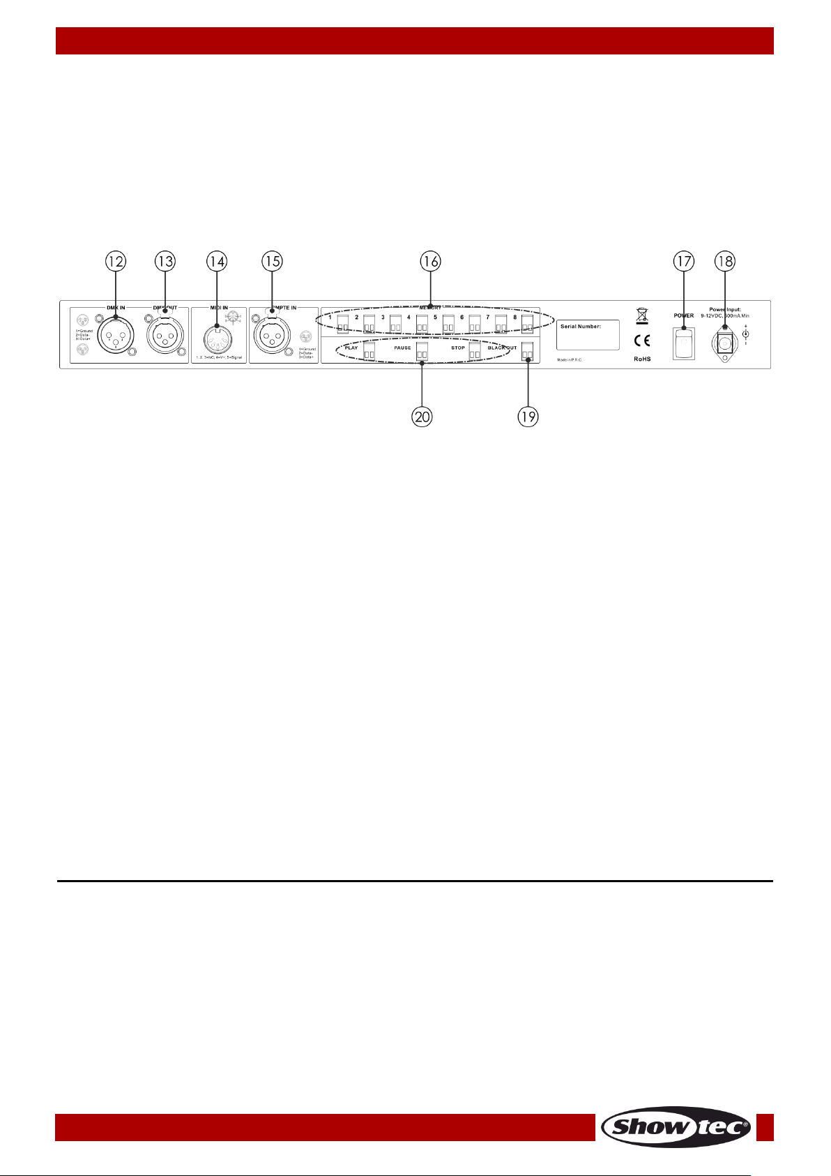
Fig. 02
09) DMX input LED indicator
This indicator will light up when DMX signal is being received.
10) DMX output LED indicator
This indicator will light up when DMX signal is being sent to the other connected devices.
11) SD card port
Use this port to insert an SD card for data transmission.
Backside
12) 3-pin DMX signal connector IN
Use a 3-pin XLR cable in order to send DMX data from a light controller to the DR Pro Rack.
13) 3-pin DMX signal connector OUT
Use a 3-pin XLR cable in order to send DMX data from the DR Pro Rack to the connected light fixture.
14) 5-pin MIDI signal connector IN
Use a 5-pin MIDI cable to connect the DR Pro Rack to a MIDI source. With you MIDI source, you are
able to call up the recorded scenes, shows and chases.
15) 3-pin XLR SMPTE signal connector IN
Use a 3-pin XLR cable to send SMPTE signal to the DR Pro Rack.
16) 2-pin memory connectors 1-8
Connect those connectors to remote controls. In this way, it is no more needed to press the Memory
buttons 1-8 (05).
17) Power switch ON/OFF
18) DC 9V, 500mA power connector
Connect the included DC 9V, 500mA power adapter.
19) 2-pin BLACKOUT connector
Connect those connectors to remote controls. In this way, it is no more needed to press the
BLACKOUT button (07).
20) 2-pin PLAY/PAUSE/STOP connectors
Connect those connectors to remote controls. In this way, it is no more needed to press the
PLAY/PAUSE/STOP buttons (06).
Installation
Remove all packing materials from the DR Pro Rack. Check that all foam and plastic padding is
removed. Connect all cables.
Do not supply power before the whole system is set up and connected properly.
Always disconnect from electric mains power supply before cleaning or servicing.
Damages caused by non-observance are not subject to warranty.
7
Page 9
Ordercode: 50821
DR Pro Rack
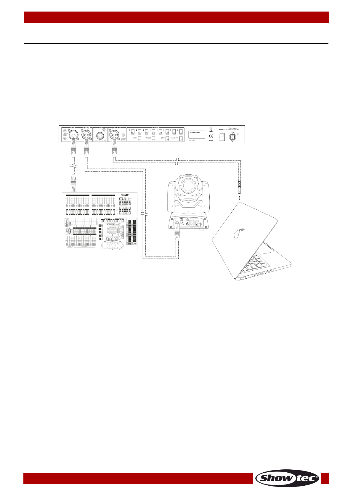
There are 5 modes:
DMX recording mode
Time Trigger
SMPTE/MIDI Trigger
DMX Trigger
DMX Monitor
Fig. 03
Set Up and Operation
Follow the directions below, as they pertain to your preferred operation mode.
Before plugging the unit in, always make sure that the power supply matches the product specification
voltage. Do not attempt to operate a 120V specification product on 230V power, or vice versa.
Control Modes
Note : Link all cables before connecting electric power
Data Cabling
To link fixtures together you must obtain data cables. You can purchase DAP Audio certified DMX cables
directly from a dealer/distributor or construct your own cable. If you choose to create your own cable
please use data-grade cables that can carry a high quality signal and are less prone to electromagnetic
interference.
DAP Audio DMX Data Cables
• DAP Audio Basic microphone cable for allround use. bal. XLR/M 3-pin > XLR/F 3-pin.
Ordercode FL01150 (1,5 m), FL013 (3 m), FL016 (6 m), FL0110 (10 m), FL0115 (15 m), FL0120 (20 m).
• DAP Audio X-type data cable XLR/M 3-pin > XLR/F 3-pin. Ordercode FLX0175 (0,75 m),
FLX01150 (1,5 m), FLX013 (3 m), FLX016 (6 m), FLX0110 (10 m).
• DAP Audio cable for the demanding user with exceptional audio-qualities and connector made by
Neutrik®. Ordercode FL71150 (1,5 m), FL713 (3 m), FL716 (6 m), FL7110 (10 m).
• DAP Audio cable for the demanding user with exceptional audio-qualities and connector made by
Neutrik®. Ordercode FL7275 (0,75 m), FL72150 (1,5 m), FL723 (3 m), FL726 (6 m), FL7210 (10 m).
• DAP Audio 110 Ohm cable with digital signal transmission. Ordercode FL0975 (0,75 m),
FL09150 (1,5 m), FL093 (3 m), FL096 (6 m), FL0910 (10 m), FL0915 (15 m), FL0920 (20 m).
8
Page 10
Ordercode: 50821
DR Pro Rack
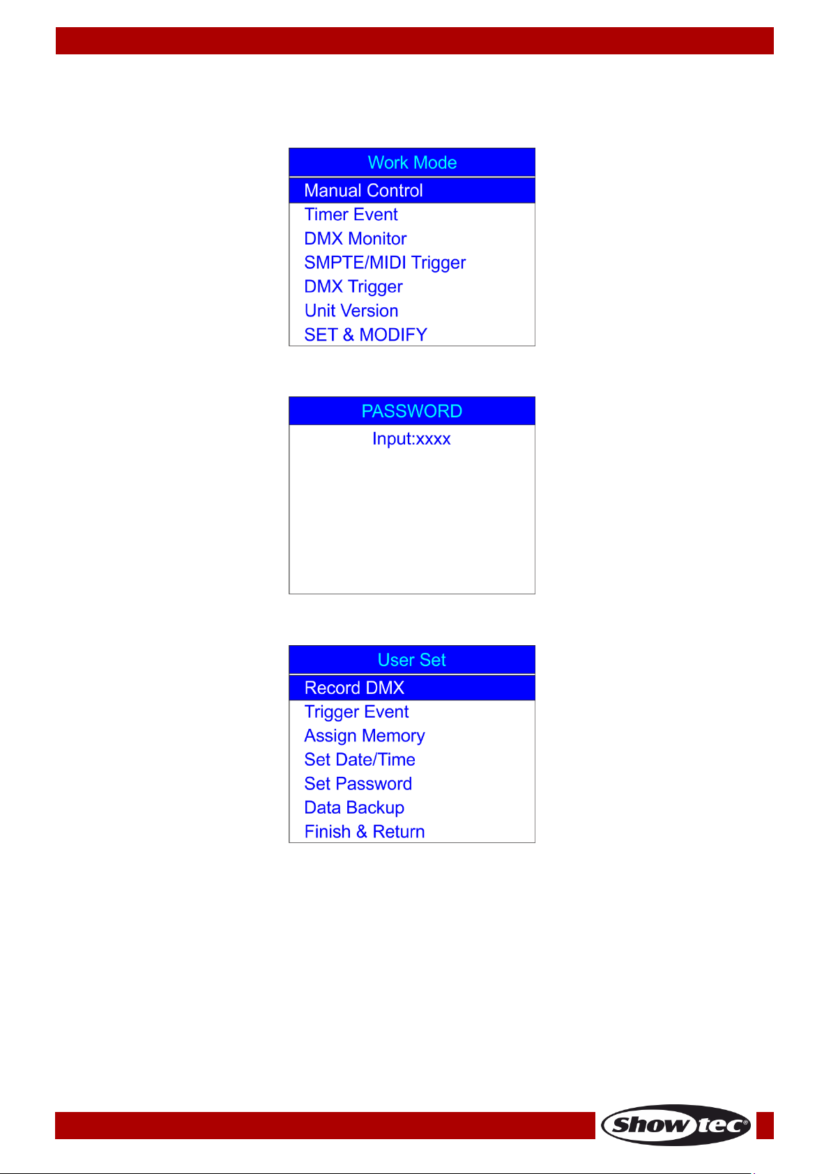
Start-up
01) Once the device is switched on, press and hold down the ENTER button for 3 seconds to open the
main menu. The display will show:
02) Press the UP/DOWN buttons, choose SET & MODIFY and press the ENTER button to open the menu.
The display will show:
03) Press the Memory buttons (05) in the following order: 1, 2, 3, 4, in order to insert the password. The
display will show:
9
Page 11
Ordercode: 50821
DR Pro Rack
1. Record DMX
With this menu you can set the scene, show and chase recording settings.
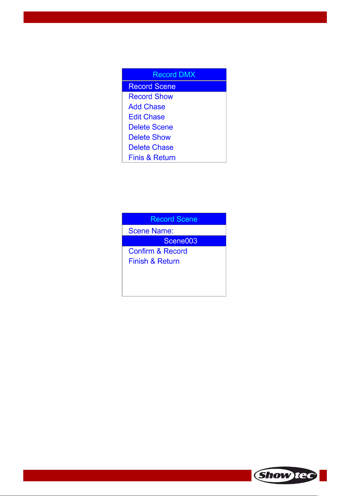
01) Press the UP/DOWN buttons to choose Record DMX and press the ENTER button to open the menu.
02) The display will show:
1.1 Recording scenes
With this menu you can record scenes, which then can be used to create chases.
01) Press the UP/DOWN buttons, choose Record Scene and press the ENTER button to open the menu.
The display will show:
02) Press the UP/DOWN buttons to choose the name of the scene and press the ENTER button.
03) Press the LEFT/RIGHT/UP/DOWN buttons to select/edit the characters in order to rename your scene.
04) Once the scene’s name has been adjusted, press the ENTER button to save.
05) Press the UP/DOWN buttons to choose Confirm & Record and press the ENTER button.
06) The scene has been saved.
07) Repeat the steps 1-6 as many times as needed.
08) Press the UP/DOWN buttons, choose Finish & Return and press the ENTER button to return to the
previous menu.
10
Page 12
Ordercode: 50821
DR Pro Rack
1.2 Recording shows
With this menu you can record shows.
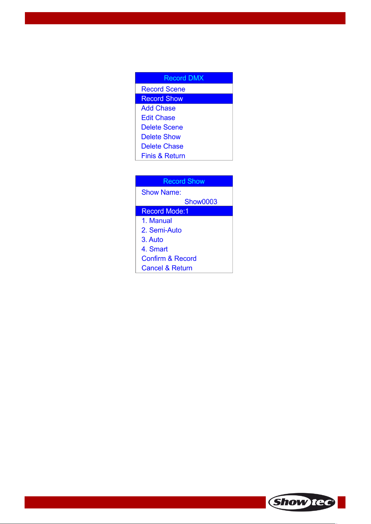
01) While in the Record DMX menu, press the UP/DOWN buttons to choose Record Show. The display will
show:
02) Press the ENTER button to open the menu. The display will show:
03) Press the UP/DOWN buttons to choose the scene’s name and press the ENTER button.
04) Press the LEFT/RIGHT/UP/DOWN buttons to select/edit the characters in order to rename your show.
09) Once the show’s name has been adjusted, press the ENTER button to save.
05) Press the UP/DOWN buttons to choose Record Mode.
06) Press the ENTER button to edit the current recording mode.
07) Press the UP/DOWN buttons to select one of the following recording modes:
1. Manual: In this mode, you need to press the PLAY button to start and the STOP button to stop the
recording.
2. Semi-Auto: In this mode, the recording will start on its own but you still need to press the STOP
button to stop the recording.
3. Auto: In this mode, the recording will start as soon as DMX data is received. The recording will stop
when no DMX data is detected.
4. Smart: This mode is used in combination with DMX data which undergoes changes, when being
sent. Under normal circumstances, DMX data does not change.
08) Once you have selected the desired recording mode, press the ENTER button to save.
09) If you decide not to record any show, press the UP/DOWN buttons to choose Cancel & Return and
press the ENTER button to return to the previous menu.
10) If you decide to record a show, press the UP/DOWN buttons to choose Confirm & Record and press
the ENTER button to open the menu. The display will show:
11
Page 13

Ordercode: 50821
DR Pro Rack
11) Press the UP/DOWN buttons to choose Start Record and press the ENTER button to start recording.
12) Press the ENTER button again to pause the recording, and again to resume.
13) If the recording is completed, press the UP/DOWN buttons to choose Stop & Return and press the
ENTER button to return to the previous menu.
1.3 Adding chases
With this menu you can add a chase, consisting of the previously saved scenes.
01) While in the Record DMX menu, press the UP/DOWN buttons to choose Add Chase. The display will
show:
02) Press the ENTER button to open the menu. The display will show:
03) Press the UP/DOWN buttons to choose the name of the chase and press the ENTER button.
04) Press the LEFT/RIGHT/UP/DOWN buttons to select/edit the characters in order to rename your chase.
05) Once the chase’s name has been adjusted, press the ENTER button to save.
06) Press the UP/DOWN buttons to toggle between the following options:
Cur-Step: Shows the current step/total number of steps.
SCENE01.:Shows the name of the current scene and the number of the current scene/total number
of scenes.
HoldTime: Press the ENTER button to edit the hold time. Press the LEFT/RIGHT/UP/DOWN buttons to
select/edit the time values. Press the ENTER button to save.
12
Page 14

Ordercode: 50821
DR Pro Rack
FadeTime: Press the ENTER button to edit fade time. Press the LEFT/RIGHT/UP/DOWN buttons to
select/edit the time values. Press the ENTER button to save.
07) Once all the options have been adjusted, press the UP/DOWN buttons to choose Confirm & Save
and press the ENTER button to save your chase and return to the previous menu.
1.4 Editing chases
With this menu, you can edit any created chase.
01) While in the Record DMX menu, press the UP/DOWN buttons to choose Edit Chase. The display will
show:
02) Press the ENTER button to open the menu. The display will show:
03) Press the UP/DOWN buttons to toggle between the available chases.
04) Press the ENTER button to open the desired chase. The display will show:
05) All the options work in the same way as in Adding chases, steps 3-7, pages 12-13.
06) Press the UP/DOWN buttons to choose the name of the current scene and press the ENTER button to
open the menu. Press the UP/DOWN buttons to toggle between the created scenes.
07) Press the UP/DOWN buttons to choose Insert Step After and press the ENTER button to add the
previously selected scene as a new step of the selected chase.
08) If you want to delete a scene, press the UP/DOWN buttons to choose Delete Current Step and press
the ENTER button to confirm.
13
Page 15
Ordercode: 50821
DR Pro Rack
09) If all the necessary changes have been made, press the UP/DOWN buttons to choose Confirm &
Return and press the ENTER button to save changes and return to the previous menu.
1.5 Deleting scenes
With this menu you can delete any selected scene.
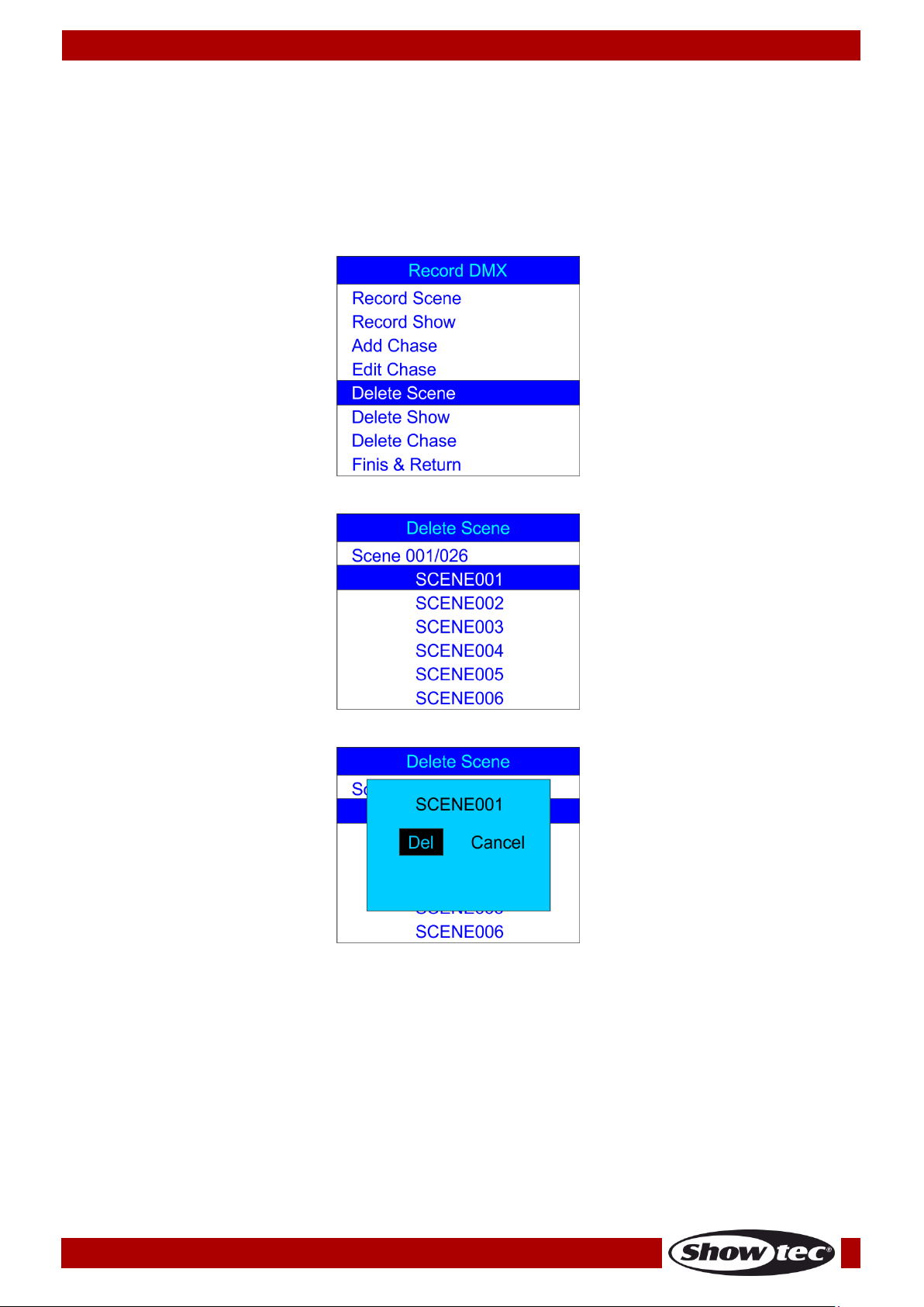
01) While in the Record DMX menu, press the UP/DOWN buttons to choose Delete Scene. The display will
show:
02) Press the ENTER button to open the menu. The display will show:
03) Press the ENTER button to select the desired scene. The display will show:
04) Press the ENTER button to delete the desired scene or, if you want to keep the scene, press the
LEFT/RIGHT buttons to choose Cancel and press the ENTER button to confirm.
05) Press the UP/DOWN buttons to choose Return and press the ENTER button to return to the previous
menu.
14
Page 16
Ordercode: 50821
DR Pro Rack
1.6 Deleting shows
With this menu you can delete any selected show.
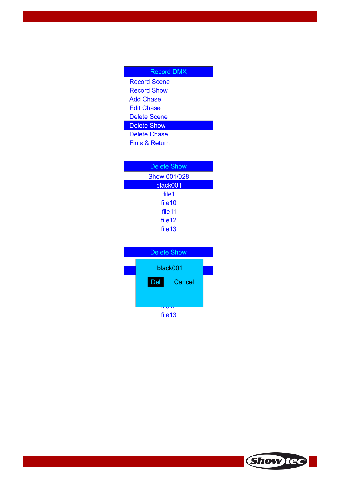
01) While in the Record DMX menu, press the UP/DOWN buttons to choose Delete Show. The display will
show:
02) Press the ENTER button to open the menu. The display will show:
03) Press the ENTER button to select the desired scene. The display will show:
04) Press the ENTER button to delete the desired show or, if you want to keep the show, press the
LEFT/RIGHT buttons to choose Cancel and press the ENTER button to confirm.
05) Press the UP/DOWN buttons to choose Return and press the ENTER button to return to the previous
menu.
15
Page 17
Ordercode: 50821
DR Pro Rack
1.7 Deleting chases
With this menu you can delete any selected chase.
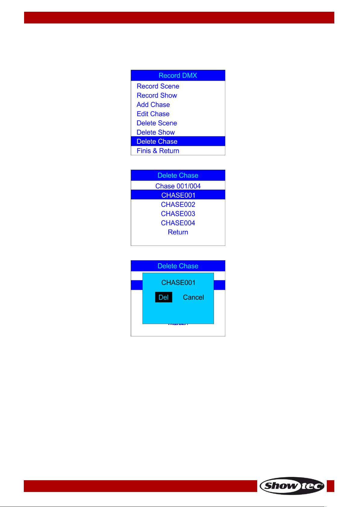
01) While in the Record DMX menu, press the UP/DOWN buttons to choose Delete Chase. The display will
show:
02) Press the ENTER button to open the menu. The display will show:
03) Press the ENTER button to select the desired scene. The display will show:
04) Press the ENTER button to delete the desired chase or, if you want to keep the chase, press the
LEFT/RIGHT buttons to choose Cancel and press the ENTER button to confirm.
05) Press the UP/DOWN buttons to choose Return and press the ENTER button to return to the previous
menu.
16
Page 18
Ordercode: 50821
DR Pro Rack
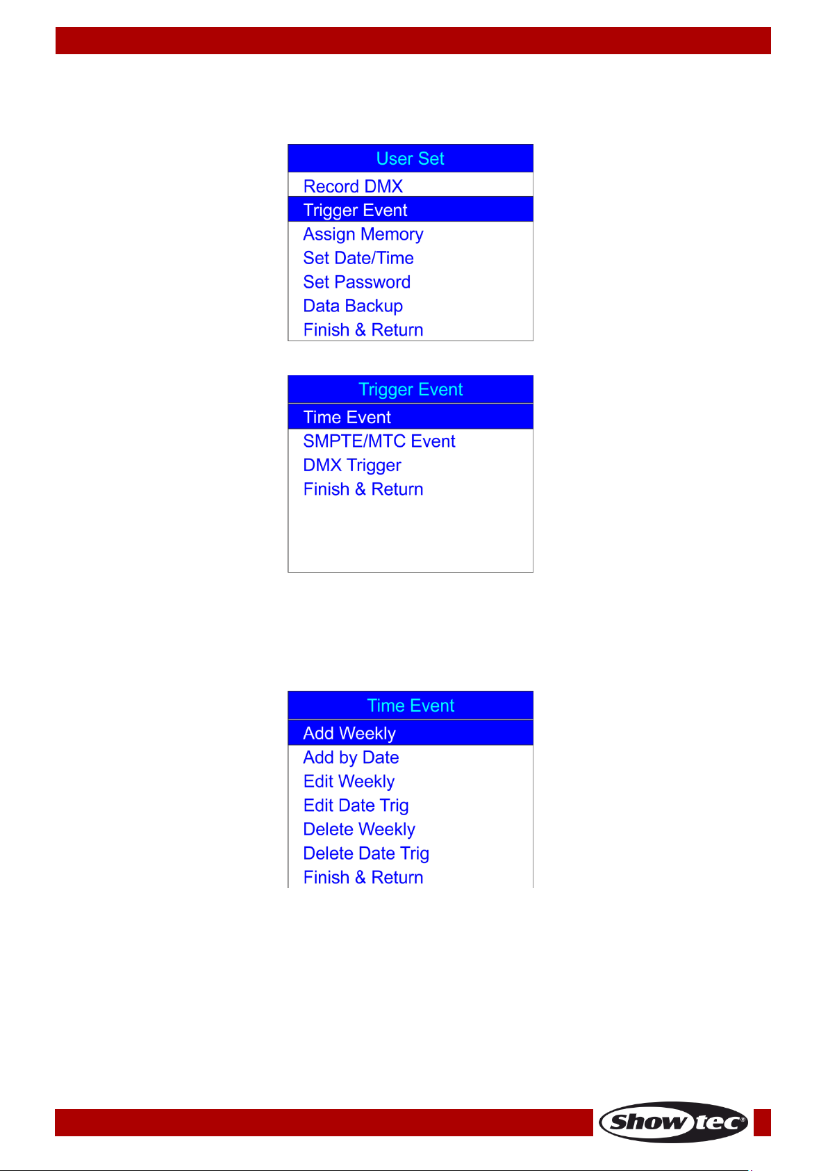
2. Trigger Event
With this menu you can set time events.
01) In SET & MODIFY menu, press the UP/DOWN buttons to choose Trigger Event. The display will show:
02) Press the ENTER button to open the menu. The display will show:
2.1. Time Event
With this menu you can set periods of time during which the DR Pro Rack will take the desired actions.
01) Press the UP/DOWN buttons to choose Time Event and press the ENTER button to open the menu.
The display will show:
17
Page 19

Ordercode: 50821
DR Pro Rack
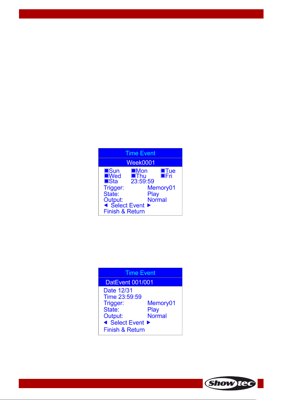
02) Press the UP/DOWN buttons to choose Add Weekly and press the ENTER button to open the menu.
The display will show:
03) Press the UP/DOWN buttons to choose the name of the event and press the ENTER button to edit its
name.
04) Press the LEFT/RIGHT/UP/DOWN buttons to select/edit the characters. Once the name has been
adjusted, press the ENTER button to confirm.
05) Press the UP/DOWN buttons to choose the names of the day on which the event will take place.
06) Press the ENTER button to open the edition mode.
07) Press the LEFT/RIGHT/UP/DOWN buttons to select and deactivate/activate the desired day of the
week, as well as the starting time.
08) Once all the changes have been made, press the ENTER button to confirm.
09) Press the UP/DOWN buttons to choose Trigger and press the ENTER button to open the menu.
10) Press the UP/DOWN buttons to choose one of the available options:
Memory 1-8: choose one of the available 8 memory channels.
Play Memo: the device will play all 8 available memory channels.
StopMemo: the device will stop the memory playback.
BlackOutMe: the device will black the playback out.
11) Press the UP/DOWN buttons to choose State and press the ENTER button to open the menu.
12) Press the UP/DOWN buttons to choose one of the 3 options: Play/Pause/Stop.
13) Press the UP/DOWN buttons to choose Output and press the ENTER button to open the menu.
14) Press the UP/DOWN buttons to choose one of the 2 options: Normal or BlackOut.
15) Press the ENTER button to confirm your choice.
16) Once the changes have been made, press the UP/DOWN buttons to choose Confirm & Save and
press the ENTER button to save the event.
17) Press the UP/DOWN buttons to choose Finish & Return and press the ENTER button to return to the
previous menu.
18) Return to step 1, press the UP/DOWN buttons to choose Add by Date and press the ENTER button to
open the menu. The display will show:
19) Press the UP/DOWN buttons to choose the name of the event and press the ENTER button.
20) Press the LEFT/RIGHT/UP/DOWN buttons to select/edit the characters.
21) Once the name has been adjusted, press the ENTER button to confirm.
22) Press the UP/DOWN buttons to choose Date and press the ENTER button to open the menu.
23) Press the LEFT/RIGHT/UP/DOWN buttons to set the desired month and day.
18
Page 20
Ordercode: 50821
DR Pro Rack
24) Press the ENTER button to confirm.
25) Press the UP/DOWN buttons to choose Trigger and press the ENTER button to open the menu.
26) Press the UP/DOWN buttons to choose one of the available options:
Memory 1-8: choose one of the available 8 memory channels.
Play Memo: the device will play all 8 available memory channels.
StopMemo: the device will stop the memory playback.
BlackOutMe: the device will black the playback out.
No Memory: No memory is chosen.
27) Press the UP/DOWN buttons to choose State and press the ENTER button to open the menu.
28) Press the UP/DOWN buttons to choose one of the 3 options: Play/Pause/Stop.
29) Press the UP/DOWN buttons to choose Output and press the ENTER button to open the menu.
30) Press the UP/DOWN buttons to choose one of the 2 options: Normal or BlackOut.
31) Press the ENTER button to confirm your choice.
2.1.1 Editing time events
With this menu you can edit the previously created time events.
01) In Time Event menu, press the UP/DOWN buttons to choose Edit Weekly and press the ENTER button to
open the menu. The display will show:
02) Press the UP/DOWN buttons to choose Select Event and press the LEFT/RIGHT buttons to choose the
event which you want to edit.
03) Edition can be carried out in exactly the same way as in case of creating a weekly event (steps 1-17,
pages 17-18).
04) Once all the changes have been made, press the UP/DOWN buttons to choose Finish & Return and
press the ENTER button to save and return to the previous menu.
05) Press the UP/DOWN buttons to choose Edit Date Trig and press the ENTER button to open the menu.
The display will show:
06) Press the UP/DOWN buttons to choose Select Event and press the LEFT/RIGHT buttons to choose the
event which you want to edit.
07) The edition can be carried out in exactly the same way as in case of creating a date event (steps
18-31, pages 19-20).
19
Page 21
Ordercode: 50821
DR Pro Rack
08) Once all the changes have been made, press the UP/DOWN buttons to choose Finish & Return and
press the ENTER button to save and return to the previous menu.
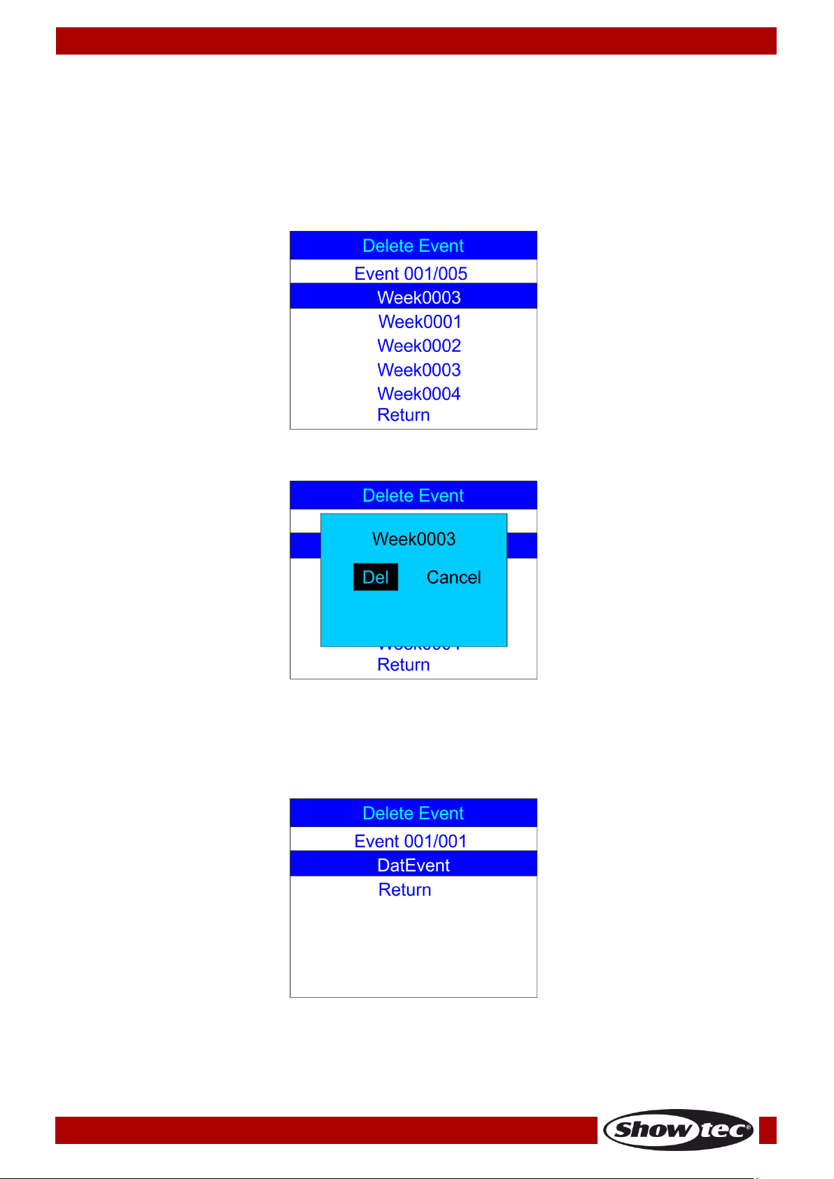
2.1.2 Deleting time events
With this menu you can delete the previously created time events.
01) In Time Event menu, press the UP/DOWN buttons to choose Delete Weekly and press the ENTER
button to open the menu. The display will show:
02) Press the UP/DOWN buttons to select the desired weekly event.
03) Press the ENTER button to open the menu. The display will show:
04) Press the ENTER button to delete the desired event or, if you want to keep the event, press the
LEFT/RIGHT buttons to choose Cancel and press the ENTER button to confirm.
05) Press the UP/DOWN buttons to choose Return and press the ENTER button to return to the previous
menu.
06) Return to 2.1 Time Event step 1, page 17. Press the UP/DOWN buttons to choose Delete Date Trig and
press the ENTER button to open the menu. The display will show:
07) Press the UP/DOWN buttons to select the desired date event.
20
Page 22
Ordercode: 50821
DR Pro Rack
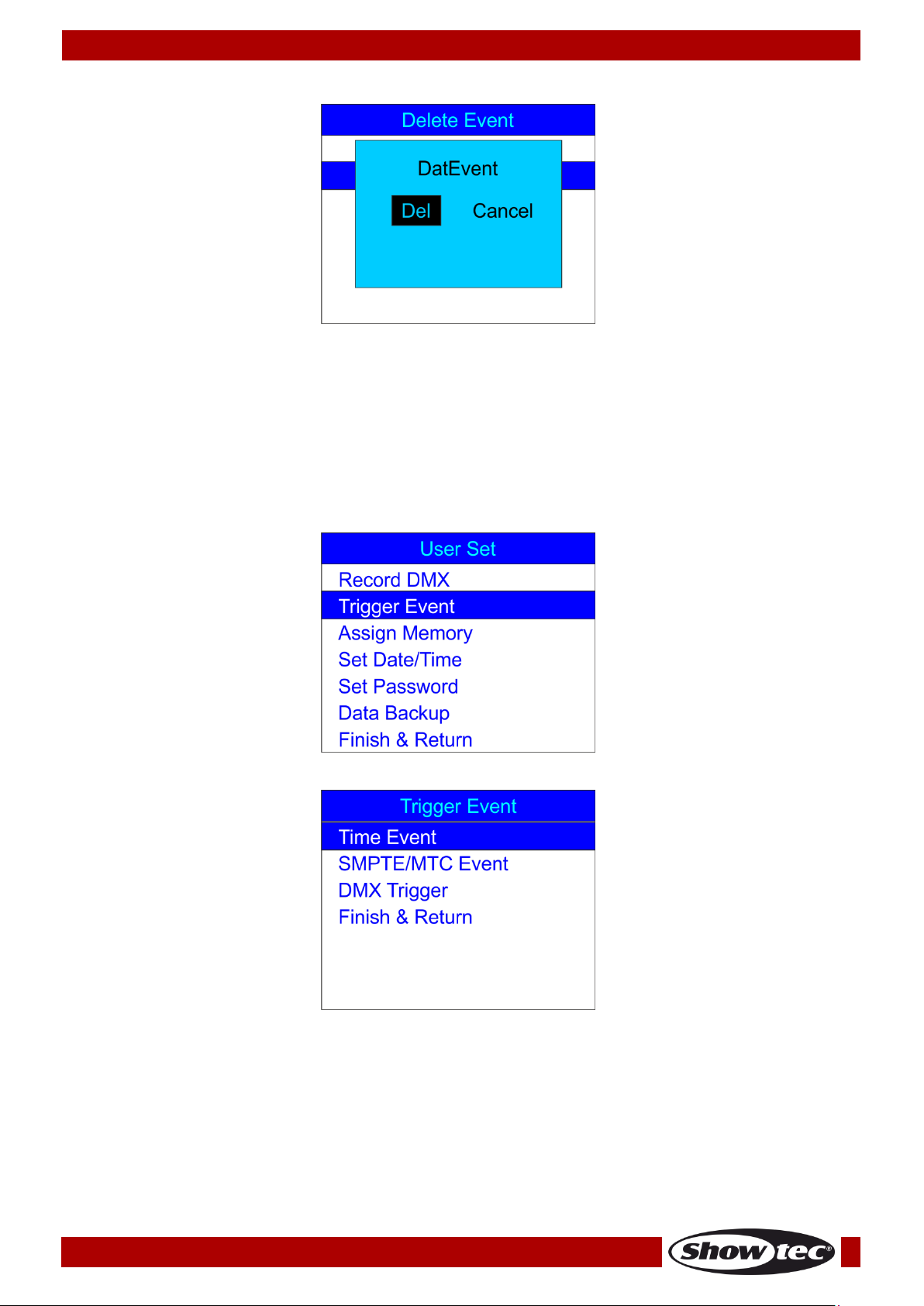
08) Press the ENTER button to open the menu. The display will show:
09) Press the ENTER button to delete the desired event or, if you want to keep the event, press the
LEFT/RIGHT buttons to choose Cancel and press the ENTER button to confirm.
10) Press the UP/DOWN buttons to choose Return and press the ENTER button to return to the previous
menu.
2.2. SMPTE/MTC Event
With this menu you can set SMPTE/MTC triggered events.
01) In SET & MODIFY menu, press the UP/DOWN buttons to choose Trigger event. The display will show:
02) Press the ENTER button to open the menu. The display will show:
21
Page 23

Ordercode: 50821
DR Pro Rack
03) Press the UP/DOWN buttons to choose SMPTE/MTC Event and press the ENTER button to open the
menu. The display will show:
2.2.1 Adding SMPTE/MTC events
With this menu you can create SMPTE/MTC events.
01) Press the UP/DOWN buttons to choose Add SMPTE/MTC and press the ENTER button to open the
menu. The display will show:
02) Press the UP/DOWN buttons to choose the name of the event and press the ENTER button to open
the menu.
03) Press the LEFT/RIGHT/UP/DOWN buttons to select/edit the characters. Once the name has been
adjusted, press the ENTER button to confirm.
04) Press the UP/DOWN buttons to choose Frame Rate and press the ENTER button to open the menu.
05) Press the UP/DOWN buttons to choose the desired frame rate. The adjustment range is between: 24,
25 or 30 frames/sec. Press the ENTER button to confirm your choice.
06) Press the UP/DOWN buttons to choose Frame and press the ENTER button to open the menu.
07) Press the LEFT/RIGHT/UP/DOWN buttons to select/edit the starting time of the event. Once the time
has been set, press the ENTER button to confirm.
06) Press the UP/DOWN buttons to choose Trigger and press the ENTER button to open the menu.
07) Press the UP/DOWN buttons to choose one of the available options:
Memory 1-8: choose one of the available 8 memory channels.
Play Memo: the device will play all 8 available memory channels.
StopMemo: the device will stop the memory playback.
BlackOutMe: the device will black the playback out.
No Memory: No memory is chosen.
08) Press the UP/DOWN buttons to choose State and press the ENTER button to open the menu.
09) Press the UP/DOWN buttons to choose one of the 3 options: Play/Pause/Stop.
10) Press the UP/DOWN buttons to choose Output and press the ENTER button to open the menu.
11) Press the UP/DOWN buttons to choose one of the 2 options: Normal or BlackOut.
12) Press the ENTER button to confirm your choice.
13) Once all the changes have been made, press the UP/DOWN buttons to choose Confirm & Save and
press the ENTER button to save the event.
22
Page 24
Ordercode: 50821
DR Pro Rack
14) Press the UP/DOWN buttons to choose Finish & Return and press the ENTER button to return to the
previous menu.
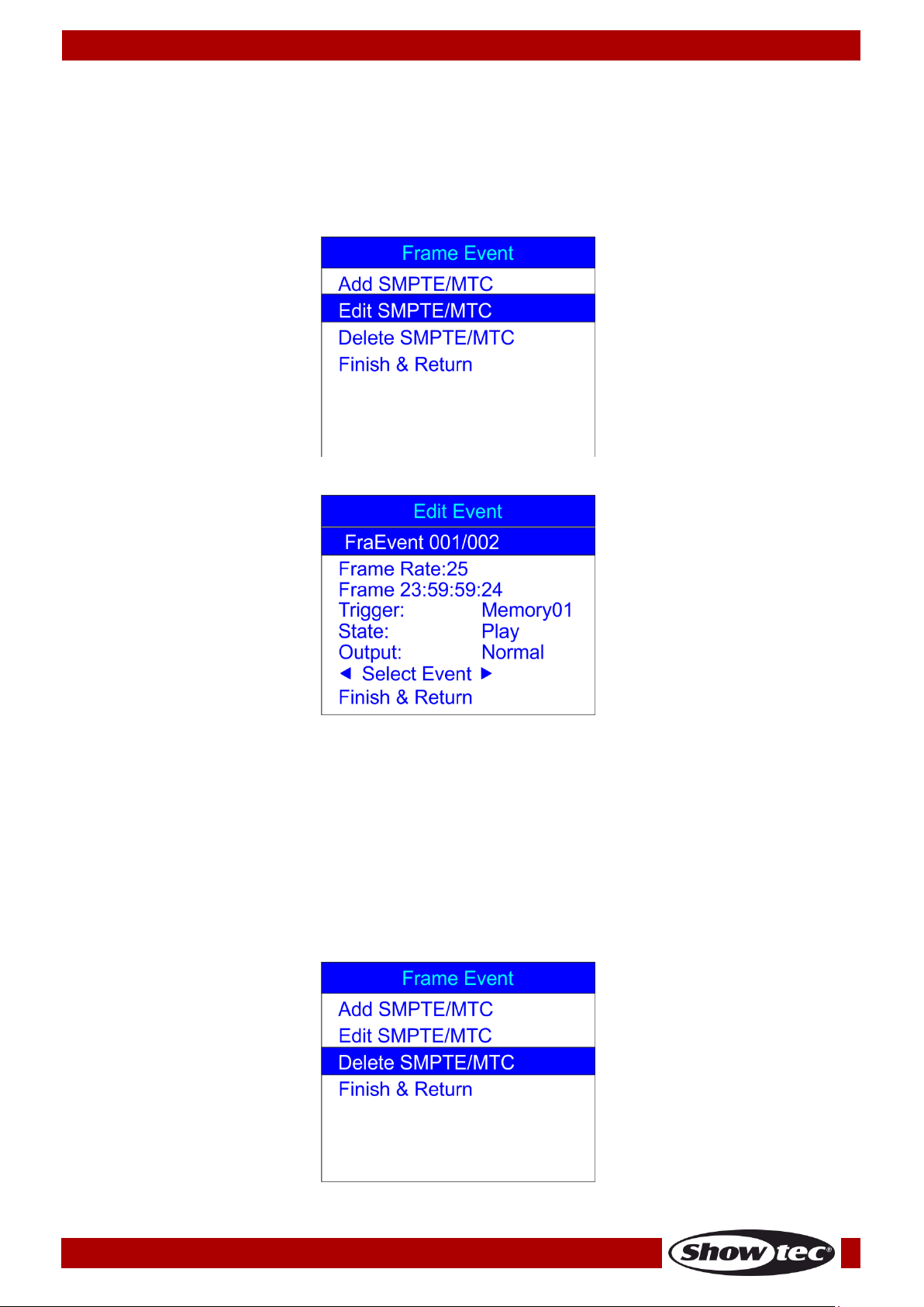
2.2.2 Editing SMPTE/MTC events
With this menu you can adjust the previously created SMPTE/MTC events.
01) In SMPTE/MTC menu, press the UP/DOWN buttons to choose Edit SMPTE/MTC. The display will show:
02) Press the ENTER button to open the menu. The display will show:
09) Press the UP/DOWN buttons to choose Select Event and press the LEFT/RIGHT buttons to choose the
event which you want to edit.
10) The edition can be carried out in exactly the same way as in case of creating an SMPTE/MTC event
(steps 1-13, page 22).
11) Once all the changes have been made, press the UP/DOWN buttons to choose Finish & Return and
press the ENTER button to return to the previous menu.
2.2.3 Deleting SMPTE/MTC events
With this menu you can delete the previously created SMPTE/MTC events.
01) In SMPTE/MTC menu, press the UP/DOWN buttons to choose Delete SMPTE/MTC. The display will show:
23
Page 25
Ordercode: 50821
DR Pro Rack
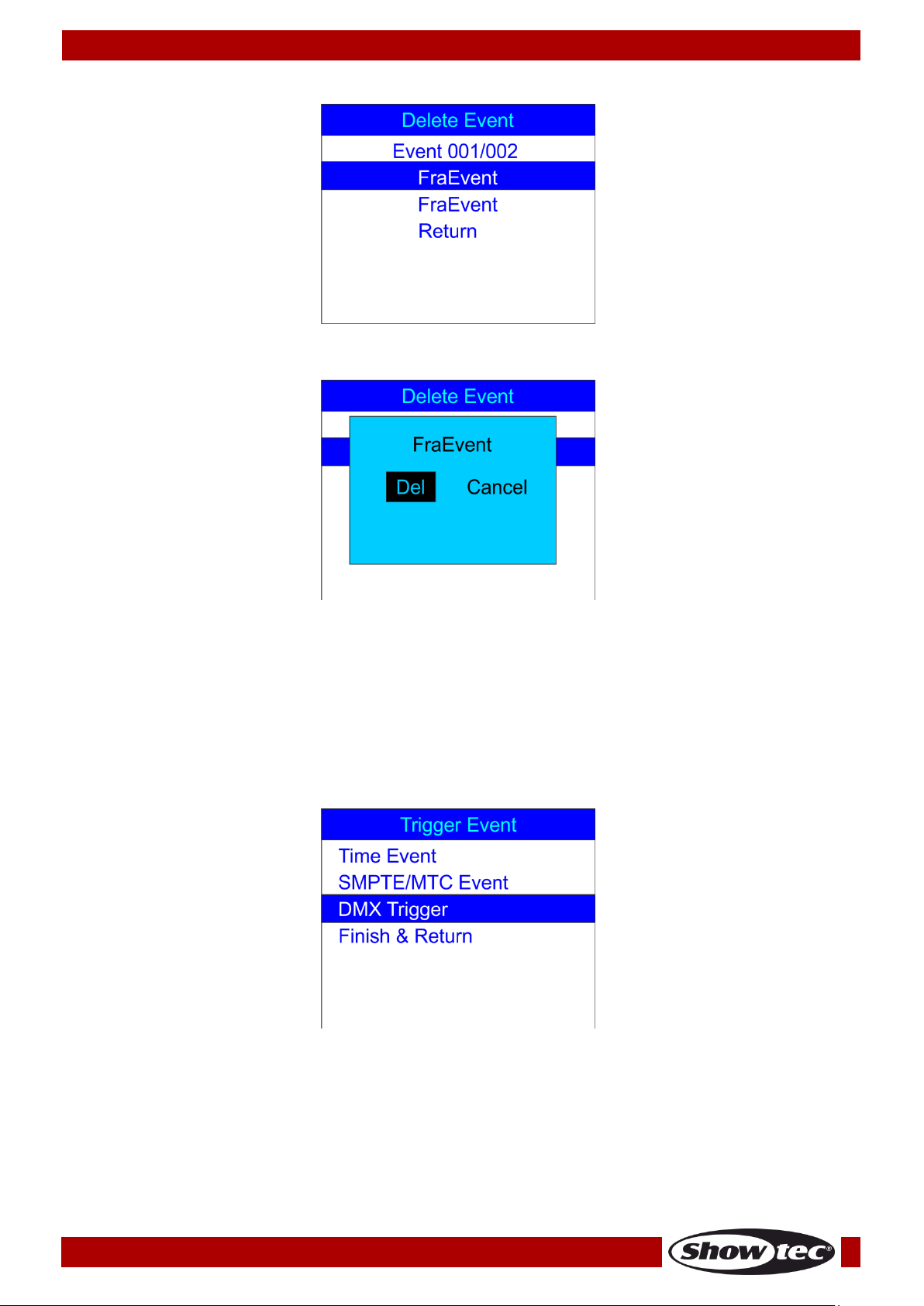
02) Press the ENTER button to open the menu. The display will show:
03) Press the UP/DOWN buttons to choose the desired event.
04) Press the ENTER button to confirm. The display will show:
05) Press the ENTER button to delete the desired event or, if you want to keep the event, press the
LEFT/RIGHT buttons to choose Cancel and press the ENTER button to confirm.
06) Press the UP/DOWN buttons to choose Return and press the ENTER button to return to the previous
menu.
2.3. DMX trigger
With this menu you can set the DMX/SMPTE settings of the device.
01) In Trigger Event menu, press the UP/DOWN buttons to choose DMX Trigger. The display will show:
24
Page 26

Ordercode: 50821
DR Pro Rack
02) Press the ENTER buton to open the menu. The display will show:
03) Press the UP/DOWN buttons to choose DMX Start Address and press the ENTER button to open the
menu.
04) Press the LEFT/RIGHT/UP/DOWN buttons to select/edit the digits and set the desired DMX address.
The adjustment range is between 001-510. The chosen DMX address needs to be the same as the
DMX address of the connected light fixture.
05) Once the DMX address has been set, press the ENTER button to confirm.
06) Press the UP/DOWN buttons to choose No DMX and press the ENTER button to open the menu.
07) Press the UP/DOWN buttons to choose one of the following 4 options:
Manual: Manual Mode will be chosen if there is not any DMX signal received.
Timer: Time trigger will be chosen if there is not any DMX signal received.
Last Hold: Last active mode will be chosen if there is not any DMX signal received.
Black Out: Blackout will be performed if there is not any DMX signal received.
08) Press the ENTER button to confirm your choice.
09) Press the UP/DOWN buttons to choose No SMPTE/MIDI IN and press the ENTER button to open the
menu.
10) Press the UP/DOWN buttons to choose one of the following 4 options:
Manual: Manual Mode will be chosen if there is not any SMPTE/MIDI signal received.
Timer: Time trigger will be chosen if there is not any SMPTE/MIDI signal received.
Last Hold: Last active mode will be chosen if there is not any SMPTE/MIDI signal received.
Black Out: Blackout will be performed if there is not any SMPTE/MIDI signal received.
11) Once all the changes have been made, press the UP/DOWN buttons to choose Finish & Return and
press the ENTER button to return to the previous menu.
3. Assign Memory
With this menu, you can assign all the created scenes, shows and chases to the available memory
channels.
01) In SET & MODIFY menu, press the UP/DOWN buttons to choose Assign Memory. The display will show:
25
Page 27
Ordercode: 50821
DR Pro Rack
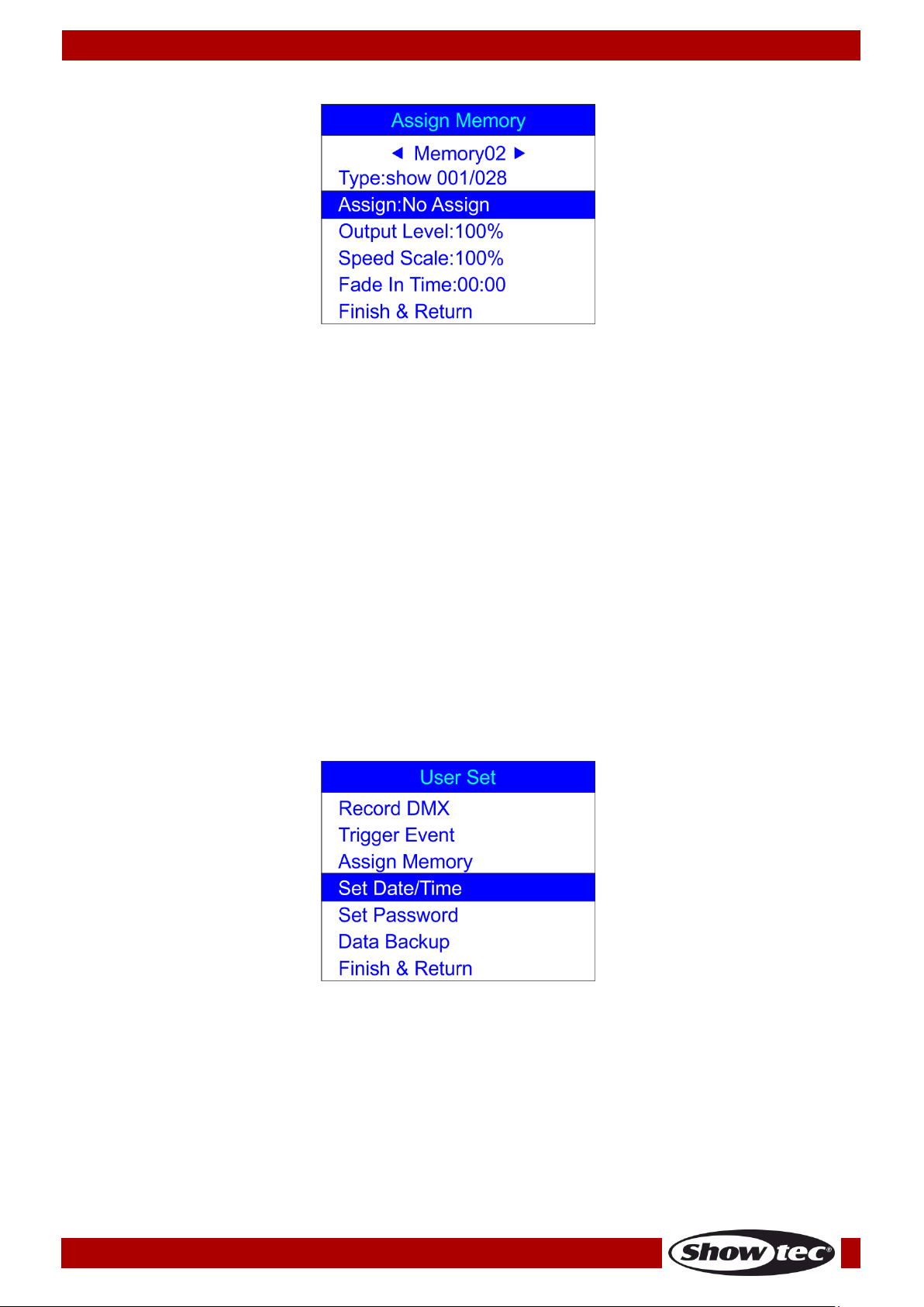
02) Press the ENTER button to open the menu. The display will show:
03) Press the UP/DOWN button to choose the memory name and press the ENTER button to open the
menu.
04) Press the UP/DOWN buttons to choose one of the available 8 memory channels.
05) Press the UP/DOWN buttons to toggle between the following options:
Type: Choose the group of files which you want to assign to the current memory channel
(scene, show or chase).
Assign: Toggle between the created scenes, shows and chases.
Output Level: Set the output level, between 0-100%.
Speed Scale: Set the speed, between 0-100%.
Fade In Time (show): The amount of time after which the chosen show will be displayed.
Fade Time (scene): The amount of time which separates the current and the following scene.
06) Press the ENTER button to open the desired menu and press the UP/DOWN buttons to adjust the
options.
07) Once all the changes have been made, press the UP/DOWN buttons to choose Finish & Return and
press the ENTER button to return to the previous menu.
4. Set Date/Time
With this menu, you can set the current date and time.
01) In SET & MODIFY menu, press the UP/DOWN buttons to choose Set Date/Time. The display will show:
26
Page 28

Ordercode: 50821
DR Pro Rack
02) Press the ENTER button to open the menu. The display will show:
03) Press the UP/DOWN buttons to toggle between the options.
04) Press the ENTER button to open the menu.
05) Press the LEFT/RIGHT/UP/DOWN buttons to select/edit the values.
06) Once the time and date are set, press the UP/DOWN buttons to choose Save & Return and press the
ENTER button to return to the previous menu.
5. Set Password
With this menu, you can set the password, which you need to insert if you want to adjust the device’s
settings.
01) In SET & MODIFY menu, press the UP/DOWN buttons to choose Set Password. The display will show:
02) Press the ENTER button to open the menu. The display will show:
03) Press the UP/DOWN buttons to choose Old Password and press the ENTER button to open the menu.
04) Insert the current password (1,2,3,4).
05) The selection bar will automatically move to New Password. Now, insert the new password of your
own choice.
06) The selection bar will automatically move to Input Again. Now, reinsert the new password.
27
Page 29

Ordercode: 50821
DR Pro Rack
07) The selection bar will automatically move to Confirm & Save. Press the ENTER button to save the new
password.
6. Data backup
With this menu, you can make a safety backup of your created scenes, shows and chases. You can also
import data from your SD card to the DR Pro Rack.
01) In SET & MODIFY menu, press the UP/DOWN buttons to choose Data Backup. The display will show:
02) Press the ENTER button to open the menu. The display will show:
03) Press the UP/DOWN buttons to toggle between the available options.
28
Page 30

Ordercode: 50821
DR Pro Rack
04) Once you have chosen the desired option, press the ENTER button to import/export files. The display
will show:
05) The desired data is now saved.
06) Press the UP/DOWN buttons to choose Finish & Return to return to the previous menu.
29
Page 31
Ordercode: 50821
DR Pro Rack
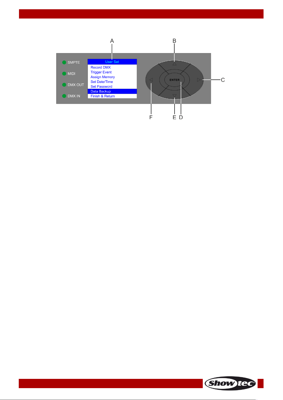
Fig. 04
A) LCD display
D) ENTER button
B) UP button
E) DOWN button
C) RIGHT button
F) LEFT button
Control Panel
Control Mode
The fixture is individually addressed on a data-link and connected to the controller.
The fixture responds to the DMX signal from the controller. (When you select the DMX address and save it,
the controller will display the saved DMX address, next time.)
DMX Addressing
Please note, when you use the controller, the unit has 3 channels.
Controlling:
After having addressed the DR Pro Rack fixture, you may now start operating these via your light
controller.
Note: After switching on, the DR Pro Rack will automatically detect whether DMX-512 data is received or
not. If there is no data received at the DMX-input, the “LED “ on the control panel will not flash.
If not, the problem may be:
• The XLR cable from the controller is not connected with the input of the DR Pro Rack.
• The controller is switched off or defective, the cable or connector is detective, or the signal wires are
swapped in the input connector.
Note: It is necessary to insert an XLR termination plug (with 120 Ohm) in the last fixture in order to ensure
proper transmission on the DMX data link.
30
Page 32
Ordercode: 50821
DR Pro Rack
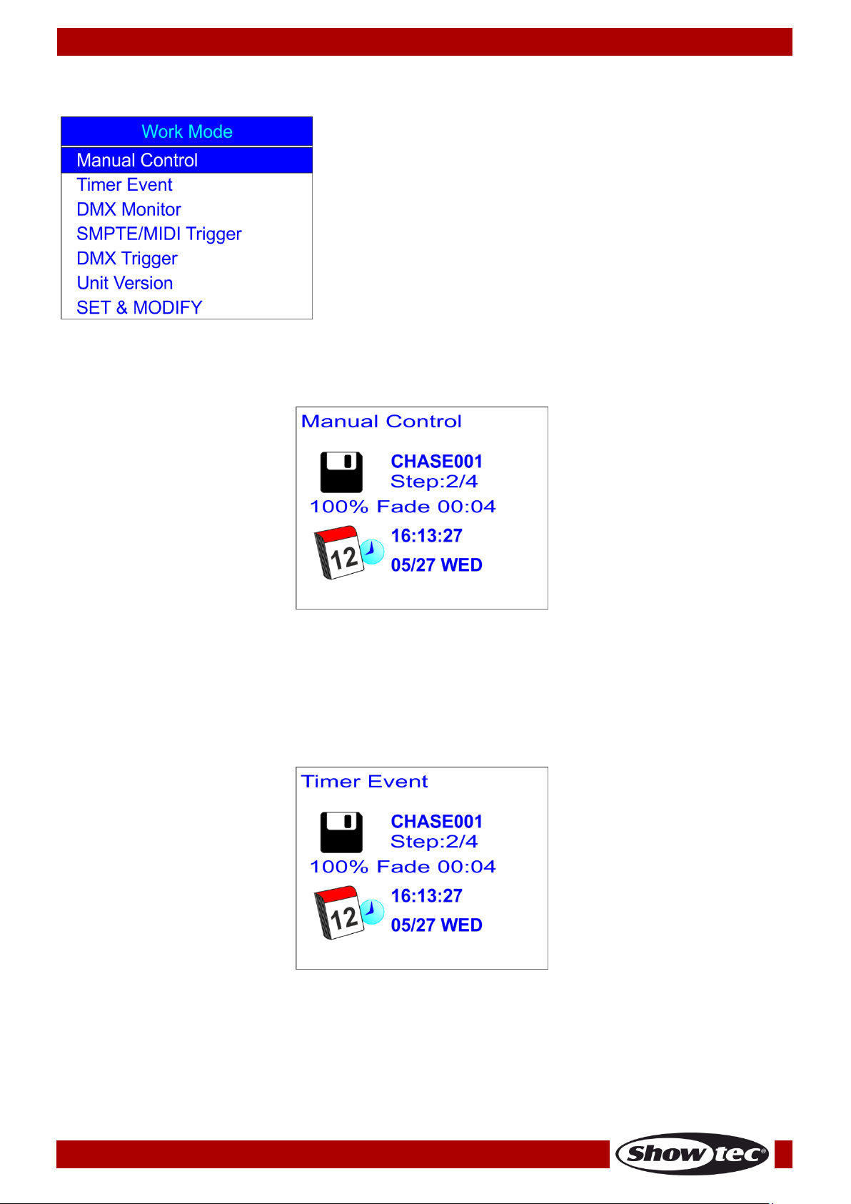
1. Manual Control
2. Timer Event
3. DMX Monitor
4. SMPTE/MIDI Trigger
5. DMX Trigger
6. Unit Version
7. SET & MODIFY
Main Menu Options
1. Manual Control
01) Press and hold down the ENTER button for 3 seconds.
02) In the main menu, press the UP/DOWN button to choose Manual Control and press the ENTER button
to open the menu. The display will show:
03) Press the Memory buttons 1-8 (05) to call up one of the previously recorded scenes, shows or chases.
04) Press the PLAY/PAUSE/STOP buttons (06) to control playback of the recorded data.
2. Timer Event
01) Press and hold down the ENTER button for 3 seconds.
02) In the main menu, press the UP/DOWN button to choose Timer Event and press the ENTER button to
open the menu. The display will show:
03) The device will now playback all scheduled time events.
31
Page 33
Ordercode: 50821
DR Pro Rack
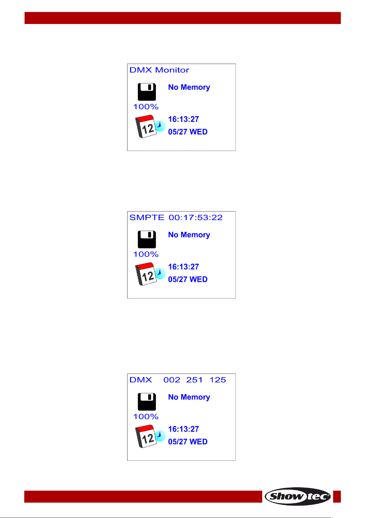
3. DMX Monitor
01) Press and hold down the ENTER button for 3 seconds.
02) In the main menu, press the UP/DOWN button to choose DMX Monitor and press the ENTER button to
open the menu. The display will show:
03) In this mode, DMX signal is received and relayed without any alterations.
4. SMPTE/MIDI Trigger
01) Press and hold down the ENTER button for 3 seconds.
02) In the main menu, press the UP/DOWN button to choose SMPTE/MIDI Trigger and press the ENTER
button to open the menu. The display will show:
03) Connect the SMPTE source to the SMPTE signal output (15) on the DR Pro Rack.
04) The device is now receiving the SMPTE time code.
5. DMX Trigger
01) Press and hold down the ENTER button for 3 seconds.
02) Connect your DMX light controller to the DMX signal connector IN (12).
03) In the main menu, press the UP/DOWN button to choose DMX Trigger and press the ENTER button to
open the menu. The display will show:
04) Move the sliders on your light controller and observe how the DR Pro Rack responds to your DMX
input. For more information, see full DMX chart, page 33.
32
Page 34
Ordercode: 50821
DR Pro Rack
0-3
Memory 1
4-7
Memory 2
8-11
Memory 3
12-15
Memory 4
16-19
Memory 5
20-23
Memory 6
24-27
Memory 7
28-255
Memory 8
0-79
Pause
80-159
Play
160-255
Stop
0-127
Normal output
128-255
Blackout
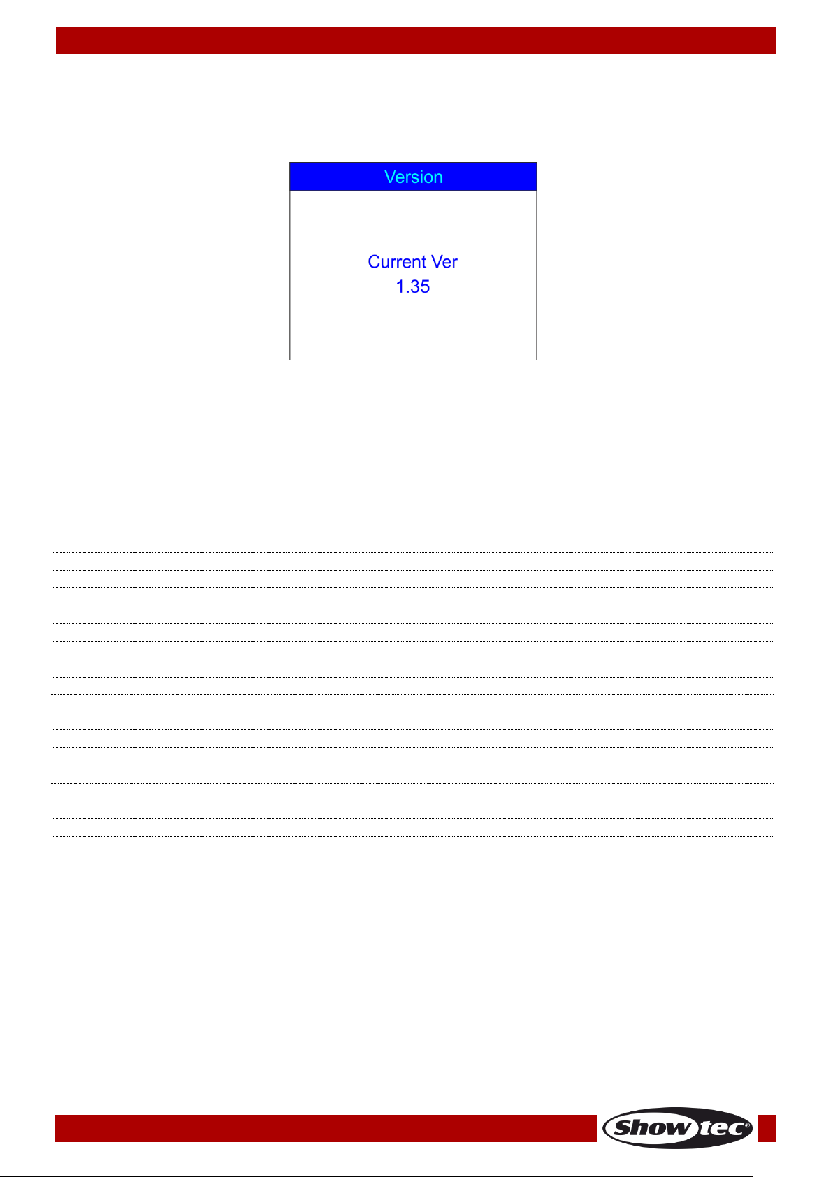
6. Unit Version
01) Press and hold down the ENTER button for 3 seconds.
02) In the main menu, press the UP/DOWN button to choose Unit Version and press the ENTER button to
open the menu. The display will show the current software version:
7. SET & MODIFY
For detailed information, see pages 9-29.
DMX Channels
3 channels
Channel 1 – Memory channels
Channel 2 – Playback
Channel 3 – Output
33
Page 35

Ordercode: 50821
DR Pro Rack
Maintenance
The Showtec DR Pro Rack requires almost no maintenance. However, you should keep the unit clean.
Disconnect the mains power supply and then wipe the cover with a damp cloth. Wipe the front glass
panel clean with glass cleaner and a soft cloth. Do not use alcohol or solvents. Do not immerse in liquid.
Keep connections clean. Disconnect electric power, and then wipe the DMX and audio connections
with a damp cloth. Make sure connections are thoroughly dry before linking equipment or supplying
electric power.
The operator has to make sure that safety-related and machine-technical installations are to be
inspected by an expert after every year in the course of an acceptance test.
The operator has to make sure that safety-related and machine-technical installations are to be
inspected by a skilled person once a year.
The following points have to be considered during the inspection:
01) All screws used for installing the device or parts of the device have to be tightly connected and must
not be corroded.
02) There may not be any deformations on housings, fixations and installation spots.
03) The electric power supply cables must not show any damages or material fatigue.
Troubleshooting
No Light
This troubleshooting guide is meant to help solve simple problems.
If a problem occurs, carry out the steps below in sequence until a solution is found. Once the unit
operates properly, do not carry out following steps.
If the light effect does not operate properly, refer servicing to a technician.
Suspect two potential problem areas as: the power supply or the LEDs.
01) Power supply. Check if the unit is plugged into an appropriate power supply.
02) The LEDs. Return your light fixture to your dealer.
03) If all of the above appears to be O.K., plug the unit in again.
04) If you are unable to determine the cause of the problem, do not open the DR Pro Rack, as this may
damage the unit and the warranty will become void.
05) Return the device to your Showtec dealer.
No Response to DMX
Response: Suspect the DMX cable or connectors, a controller malfunction, a light effect DMX card
malfunction.
01) Check the DMX setting. Make sure that DMX addresses are correct.
02) Check the DMX cable: Unplug the unit; change the DMX cable; then reconnect to electrical power.
Try your DMX control again.
03) Determine whether the DMX recorder, light controller or light effect is at fault. Does the controller
operate properly with other DMX products ? If not, take the controller in for repair. If so, take the DMX
cable and/or the light effect to a qualified technician.
34
Page 36

Ordercode: 50821
DR Pro Rack
Problem
Probable cause(s)
Remedy
One or more
fixtures do not
function at all.
No power to the fixture.
● Check if power is switched on and
cables are plugged in.
Fixtures reset
correctly, but all
respond erratically
or not at all to the
controller.
The controller is not connected.
● Connect controller.
3-pin XLR Out of the recorder does
not match XLR Out of the fixture on
the link (i.e. signal is reversed).
● Install a phase reversing cable between
the controller and the first fixture on the
link.
Fixtures reset
correctly, but some
respond erratically
or not at all to the
controller.
Poor data quality
● Check data quality. If much lower than
100 percent, the problem may be a
bad data link connection, poor quality
or broken cables, missing termination
plug, or a defective fixture disturbing
the link.
Bad data link connection
● Inspect connections and cables.
Correct poor connections. Repair or
replace damaged cables.
Data link not terminated with 120
Ohm termination plug.
● Insert termination plug in output jack of
the last fixture on the link.
Incorrect addressing of the fixtures.
● Check address setting.
3-pin XLR Out on the fixtures does
not match (pins 2 and 3 reversed).
● Install a phase-reversing cable between
the fixtures or swap pins 2 and 3 in the
fixture.
No light or lamp
cuts out
intermittently
Fixture is too hot.
● Allow fixture to cool down.
● Make sure air vents at control panel
and front lens are not blocked.
● Turn up the air conditioning .
LEDs damaged
● Disconnect fixture and return to your
dealer.
The power supply settings do not
match local AC voltage and
frequency.
● Disconnect fixture. Check settings and
correct if necessary.
35
Page 37
Ordercode: 50821
DR Pro Rack
Model:
Showtec DR Pro Rack
Input Voltage:
100-240 VAC, 60/50 Hz
Power supply:
9~12V DC power adapter, 500mA
Continuous Power:
5W
Dimensions:
482 x 78 x 44 mm (LxWxH)
19 inch x 1HE (LxH)
Weight:
1,2 kg
Operation and Programming
Signal pin OUT:
pin 1 earth, pin 2 (-), pin 3 (+)
Setup:
LCD display for easy setup
DMX channels:
3 channels
Signal input:
3-pin XLR male
Signal output:
3-pin XLR female
SMPTE input:
3-pin XLR female
MIDI input:
5-pin MIDI IN
Electro-mechanical effects
● Data signal: DMX/MIDI/SMPTE
● Control modes: DMX Recording Mode, Time Trigger, SMPTE/MIDI Trigger, DMX Trigger, DMX Monitor
● IP20 Rating
● Internal memory: 2G
● External memory: <8G
● 8 memory channels for scenes, shows and chases
● 5-hour long recording time
● SD card and USB support
● Multiple mounting possibilities
● DMX-control via standard DMX-controller: DMX-512 or DMX-1000K
● LCD display for easy setup
● Housing: grey-painted metal and ABS plastic
Max. ambient temperature ta:
40°C
Max. housing temperature tB
80°C
Minimum distance:
Minimum distance from flammable surfaces:
0,5m
Minimum distance to lighted object:
1m
Product Specification
Design and product specifications are subject to change without prior notice.
Website: www.Showtec.info
Email: service@highlite.nl
36
Page 38

Ordercode: 50821
DR Pro Rack
Dimensions
37
Page 39

Ordercode: 50821
DR Pro Rack
38
Page 40

©2015 Showtec
 Loading...