

Shop fox W1678,W1678 Instruction Manual

MODEL W1678
26" DOUBLE DRUM SANDER
INSTRUCTION MANUAL
Phone: 1-360-734-3482 • On-Line Technical Support: tech-support@shopfox.biz
COPYRIGHT © MAY, 2003 BY WOODSTOCK INTERNATIONAL, INC.
WARNING: NO PORTION OF THIS MANUAL MAY BE REPRODUCED IN ANY SHAPE OR FORM WITHOUT
THE WRITTEN APPROVAL OF WOODSTOCK INTERNATIONAL, INC.
Printed in Taiwan

WARNING
Some dust created by power sanding, sawing,
grinding, drilling, and other construction activities
contains chemicals known to the State of California
to cause cancer, birth defects or other reproductive
harm. Some examples of these chemicals are:
• Lead from lead-based paints.
• Crystalline silica from bricks, cement, and
other masonry products.
• Arsenic and chromium from chemically
treated lumber.
Your risk from these exposures varies, depending on
how often you do this type of work. To reduce your
exposure to these chemicals: work in a well
ventilated area, and work with approved safety
equipment, such as those dust masks that are
specially designed to filter out microscopic particles.

TABLE OF CONTENTS
PAGE
INTRODUCTION ....................................................................................2
About Your New 26" Double Drum Sander ......................................................2
Woodstock Service and Support....................................................................2
Warranty and Returns ................................................................................3
Specifications ................................................................................3
SAFETY ..............................................................................................4
Standard Safety Instructions ....................................................................4-5
Additional Safety Instructions for Drum Sanders ..............................................6
Avoiding Potential Injuries ..........................................................................7
ELECTRICAL REQUIREMENTS ....................................................................8
220V Operation ........................................................................................8
Extension Cords........................................................................................8
Grounding ..............................................................................................8
ASSEMBLY ........................................................................................10
Unpacking ............................................................................................10
Box Contents..........................................................................................10
Shop Preparation ....................................................................................11
Initial Cleaning ......................................................................................11
Beginning ..............................................................................................12
Dust Port and Handles ..............................................................................13
Control Box............................................................................................13
Crank and Handle....................................................................................13
ADJUSTMENTS....................................................................................14
Drums and Pressure Rollers ......................................................................14
Dust Scoop Gap ......................................................................................20
V-Belt Tension ........................................................................................21
Conveyor Belt ........................................................................................22
OPERATIONS ......................................................................................23
Overview ..............................................................................................23
Control Panel ........................................................................................23
Basic Sanding ........................................................................................24
Troubleshooting......................................................................................27
ELECTRICAL ADJUSTMENTS
ASSEMBLYSAFETYINTRODUCTION
MAINTENANCE....................................................................................29
General ................................................................................................29
Sanding Belts..........................................................................................29
Lubrication ............................................................................................30
Brush Replacement..................................................................................31
Sandpaper Replacement............................................................................21
Bearing Replacement ..............................................................................32
General Cleaning ....................................................................................34
Wiring Diagram ......................................................................................35
CLOSURE ..........................................................................................37
Parts Breakdown and Parts List ..............................................................38-45
USE THE QUICK GUIDE PAGE LABELS TO SEARCH OUT INFORMATION FAST!
OPERATIONS
MAINTENANCE
1-
-

INTRODUCTION
INTRODUCTION
About Your New 26" Double Drum Sander
Your new SHOP FOX®W1678 has been specially designed to provide many years of trouble-free service.
Close attention to detail, ruggedly built parts and a rigid quality control program assure safe and reliable
operation.
The Model W1678 features a 220V single-phase 5 HP motor, dual 4" dust ports, controls for major and
micro sanding drum adjustments, amperage measuring load meter, and many other features. Your
Double Drum Sander accepts stock up to 4
finish sanding in one pass. For further details refer to the Specifications section of this manual on Page
3.
Woodstock International, Inc. is committed to customer satisfaction in providing this manual. It is our
intent to make sure all the information necessary for safety, ease of assembly, practical use and
durability of this product be included.
If you should have any comments regarding this manual, please feel free to contact us at:
1
⁄2" thick by 26" wide, and is capable of completing rough and
Woodstock International, Inc.
Attn: Technical Department
P.O. Box 2309
Bellingham, WA 98227
Woodstock Service and Support
We stand behind our machines! In the event that a defect is found, parts are missing or questions arise
about your machine, please contact Woodstock International Service and Support at 1-360-734-3482 or
send e-mail to: tech-support@shopfox.biz
send out parts or arrange warranty returns.
. Our knowledgeable staff will help you troubleshoot problems,
-2-

Warranty and Returns
Woodstock International, Inc. warrants all SHOP FOX®machinery to be free of defects from
workmanship and materials for a period of 2 years from the date of original purchase by the original
owner. This warranty does not apply to defects due directly or indirectly to misuse, abuse, negligence
or accidents, lack of maintenance, or to repairs or alterations made or specifically authorized by anyone
other than Woodstock International, Inc.
INTRODUCTION
Woodstock International, Inc. will repair or replace, at its expense and at its option, the
SHOP FOX
machine or machine part which in normal use has proven to be defective, provided that the original
owner returns the product prepaid to the
SHOP FOX
®
factory service center or authorized repair
facility designated by our Bellingham, WA office, with proof of their purchase of the product within 2
years, and provides Woodstock International, Inc. reasonable opportunity to verify the alleged defect
through inspection. If it is determined there is no defect, or that the defect resulted from causes not
within the scope of Woodstock International Inc.'s warranty, then the original owner must bear the cost
of storing and returning the product.
This is Woodstock International, Inc.'s sole written warranty and any and all warranties that may be
implied by law, including any merchantability or fitness, for any particular purpose, are hereby limited
to the duration of this written warranty. We do not warrant that
SHOP FOX
®
machinery complies with
the provisions of any law or acts. In no event shall Woodstock International, Inc.'s liability under this
warranty exceed the purchase price paid for the product, and any legal actions brought against
Woodstock International, Inc. shall be tried in the State of Washington, County of Whatcom. We shall in
no event be liable for death, injuries to persons or property or for incidental, contingent, special or
consequential damages arising from the use of our products.
Every effort has been made to ensure that all
SHOP FOX
®
machinery meets high quality and durability
standards. We reserve the right to change specifications at any time because of our commitment to
continuously improve the quality of our products.
®
Specifications
Drum Sander Motor ............5 HP, 220 VAC, 25 Amp., 3450 RPM, 60 Hertz, Single-Phase
Drum Drive ..............................................................................Dual V-Belt
3
3
⁄4"
⁄4"
Drum Size ................................................................................6" x 27
Drum Surface Speed......................................................................2300 FPM
Drum Rotation........................................................Opposite of Feed Conveyor
1
Conveyor Motor ............................
⁄3 HP, 60 VDC, 2 amp., 60 RPM, Varable Speed
Conveyor Drive ................................................................Sprocket and Chain
Conveyor Surface Speed ................................................................0-20 FPM
1
Maximum Lumber Dimensions ..........................................4
Minimum Lumber Dimensions ..............................................
⁄2" Thick x 26" Wide
1
⁄8" Thick x 9" Long
Dust Port O.D. ......................................................................................4"
1
Conveyor Table Size ................................................................26
⁄8" x 301⁄4"
Stand ......................................................Cabinet Style, Powder Coated Paint
Bearings ......................Both Serviceable and Permanently-Lubricated Ball Bearings
Power Control ................................Magnetic Switch, with Emergency Shut-Down
Footprint ................................................................................36" x 23
Shipping Weight ............................................................................435 lbs.
-3-

SAFETY
READ MANUAL BEFORE OPERATING MACHINE.
FAILURE TO FOLLOW INSTRUCTIONS BELOW WILL
RESULT IN PERSONAL INJURY.
SAFETY
NOTICE
Indicates an imminently hazardous situation which, if not avoided, WILL
result in death or serious injury.
Indicates a potentially hazardous situation which, if not avoided, COULD
result in death or serious injury.
Indicates a potentially hazardous situation which, if not avoided, MAY
result in minor or moderate injury.
This symbol is used to alert the user to useful information about proper
operation of the equipment, and/or a situation that may cause damage
to the machinery.
Standard Safety Instructions
1. Thoroughly read the Instruction Manual before operating your machine. Learn the applications,
limitations and potential hazards of this machine. Keep the manual in a safe and convenient place
for future reference.
2. Keep work area clean and well lighted. Clutter and inadequate lighting invite potential hazards.
3. Ground all tools. If a machine is equipped with a three-prong plug, it must be plugged into a three-
hole grounded electrical receptacle or grounded extension cord. If using an adapter to aid in
accommodating a two-hole receptacle, ground using a screw to a known ground.
4. Wear eye protection at all times. Use safety glasses with side shields or safety goggles that meet
the appropriate standards of the American National Standards Institute (ANSI).
5. Avoid dangerous environments. Do not operate this machine in wet or open flame environments.
Airborne dust particles could cause an explosion and severe fire hazard.
6. Ensure all guards are securely in place and in working condition.
7. Make sure switch is in the OFF position before connecting power to machine.
8. Keep work area clean, free of clutter, grease, etc.
9. Keep children and visitors away. Visitors must be kept at a safe distance while operating unit.
10. Childproof your workshop with padlocks, master switches or by removing starter keys.
11. Stop and disconnect the machine when cleaning, adjusting or servicing.
-4-

12. Do not force tool. The machine will do a safer and better job at the rate for which it was designed.
13. Use correct tool. Do not force machine or attachment to do a job for which it was not designed.
14. Wear proper apparel. Do not wear loose clothing, neck ties, gloves, jewelry, and secure long hair
away from moving parts.
15. Remove adjusting keys, rags, and tools. Before turning the machine on, make it a habit to check
that all adjusting keys and wrenches have been removed.
SAFETY
16.Avoid using an extension cord. But if you must use
16.
one, examine the extension cord to ensure it is in good
condition. Use
and gauge of extension cord needed for your particular
needs. The amp rating of the motor can be found on its
nameplate. If the motor is dual voltage, be sure to use
the amp rating for the voltage you will be using. If you
use an extension cord with an undersized gauge or one
that is too long, excessive heat will be generated within the circuit, increasing the chance of a fire
or damage to the circuit. Always use an extension cord that uses a ground pin and connected ground
wire. Immediately replace a damaged extension cord.
17. Keep proper footing and balance at all times.
18. Do not leave machine unattended. Wait until it comes to a complete stop before leaving the area.
19. Perform machine maintenance and care. Follow lubrication and accessory attachment instructions
in the manual.
20. Keep machine away from open flame. Operating machines near pilot lights or open flames creates
a high risk if dust is dispersed in the area. Dust particles and an ignition source may cause an
explosion. Do not operate the machine in high-risk areas, including but not limited to, those
mentioned above.
TABLE 1 to determine the correct length
Extension Cord Requirements
TABLE 1
Length and Gauge
Amp Rating 25ft 50ft 100ft
17-20 #12 #12 #10
21-30 #10 #10 N/A
21. If at any time you are experiencing difficulties
performing the intended operation, stop using
the machine! Then contact our service
department or ask a qualified expert how the
operation should be performed.
22. Habits—good and bad—are hard to break.
Develop good habits in your shop and safety will
become second-nature to you.
Always wear safety glasses or goggles when
operating equipment. Operating this
equipment creates the potential for flying
debris that can cause eye injury. Everyday
glasses or reading glasses only have impact
resistant lenses, they are not safety glasses.
Be certain the safety glasses you wear meet
the appropriate standards of the American
National Standards Institute (ANSI).
-5-
Additional Safety Instructions for Drum Sanders
INSTRUCTION MANUAL
MODEL W1678
26" DOUBLE DRUM SANDER
SAFETY
Phone: 1-360-734-3482 • On-Line Technical Support: tech-support@shopfox.biz
COPYRIGHT © MARCH, 2003 BY WOODSTOCK INTERNATIONAL, INC.
WARNING: NO PORTION OF THIS MANUAL MAY BE REPRODUCED IN ANY SHAPE OR FORM WITHOUT
THE WRITTEN APPROVAL OF WOODSTOCK INTERNATIONAL, INC.
Printed in Taiwan
Read and understand this
entire instruction manual
before using this machine.
Serious personal injury
may occur if safety and
operational information is
not understood and
followed. Do not risk your
safety by not reading!
Use this and other machinery with caution
and respect, and always consider safety
first, as it applies to your individual working
conditions. Remember, no list of safety
guidelines can be complete, and every shop
environment is different. Failure to follow
guidelines can result in serious personal
injury, damage to equipment or poor work
results.
• ALWAYS keep bystanders and yourself away from the infeed and outfeed ends when a workpiece is
fed into the sander.
• ALWAYS secure aprons, clothing, and long hair away from all sander moving parts.
• ALWAYS use a respirator along with a dust collection system when sanding. Dust from some woods is toxic,
so make sure you research the dangers of the specific species of wood you will sand.
• ALWAYS keep your hands away from the sanding drums during operation, and wear eye and hearing
protection.
• ALWAYS keep fingers away from the conveyor and the underside of the workpiece during sander and
conveyor operation. Otherwise, fingers can get pinched between the workpiece and the conveyor
belt, and pull your hand into the machine causing serious injury or death!
• ALWAYS adjust the conveyor feed rate and sanding drum height, so when you feed the workpiece
into the sander using light pressure, you do not overload the sander. Never force the workpiece into
the sander.
• ALWAYS shut the sander down, let the drums come to a complete stop, and disconnect power or
engage applicable safety-lock devices before you service, adjust, troubleshoot, or leave the
machine unattended.
• ALWAYS keep this machine in correct adjustment and properly serviced. Never attempt to clear a
jammed workpiece while the sander is running.
• ALWAYS replace the sandpaper when it is worn, and only use undamaged sandpaper.
• ALWAYS inspect the workpiece for nails, staples, knots, imbedded stones, and other material that
could be dislodged and thrown from the machine during sanding operations.
• NEVER sand if there is any doubt about the stability or integrity of the workpiece.
• NEVER sand more than one workpiece at a time.
• NEVER sand stock smaller than
• NEVER sand thin stock by using a “sled” (another board) under the workpiece.
• NEVER adjust the conveyor belt tracking when the sanding drums are engaged.
1
⁄8" thick x 9" long.
-6-
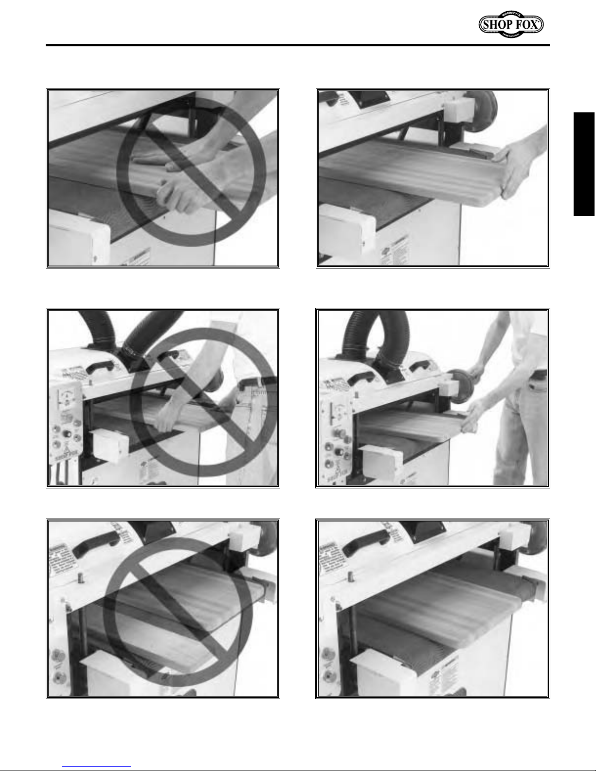
Avoiding Potential Injuries
SAFETY
Figure 1. NEVER hold the stock where the
conveyor and stock can pinch your fingers.
Figure 3. NEVER stand in the path of potential
workpiece kickback.
Figure 2. ALWAYS keep fingers away from
conveyor and the underside of the stock.
Figure 4. ALWAYS keep yourself and bystanders
away from the path of potential workpiece kickback.
Figure 5. NEVER sand more than one piece of
stock at a time.
Figure 6. ALWAYS feed the sander with only one
piece of stock at a time.
-7-
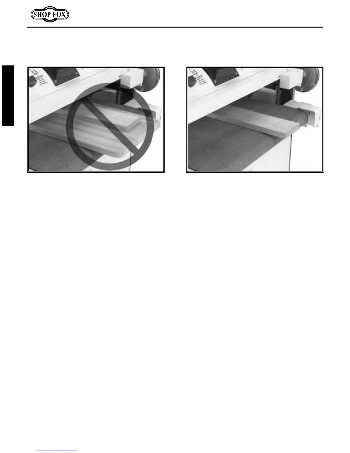
SAFETY
Figure 7. NEVER sand stock using a “sled”
(another board) under the workpiece.
Figure 8. ALWAYS sand the workpiece with it
sitting flat against the conveyor belt.
-8-

ELECTRICAL REQUIREMENTS
220V Operation
The SHOP FOX®Model W1678 Drum Sander
uses one 220 VAC single-phase motor. This
sanding drum motor is rated at 5 HP and draws
approximately 25 amps under a normal sanding
load.The
uses 60 VDC and draws approximately 2 amps.
Refer to the wiring diagram on Pages 35 and 36,
and hard wire the power supply to the sander,
or use a NEMA-style L6-30 plug and receptacle as
shown in Figure 9. In either case, the supply
circuit, circuit breaker, or fuse must be able to
carry a load of at least 27 Amps. Remember
other machines using this circuit add to the total
electrical load applied to the circuit. If this total
amperage load exceeds the amperage rating of
the circuit breaker or fuse, use a different
circuit with a higher amperage rating.
DO NOT modify an existing low-amperage circuit
by only replacing the circuit breaker with a
breaker rated for a higher amperage. The
breaker and the complete circuit must be
replaced by a qualified electrician.
1
⁄3 HP varyable speed conveyor motor
Grounding
Any electrical outlet and
circuit that you plug your
machine into must be
grounded. Serious injury or
fire may occur if this
warning is ignored!
ELECTRICAL
Ground this machine! The electrical cord
supplied with the Model W1678 does not come
with a 220 volt plug. Use a plug with a ground
pin as shown in Figure 9. If your receptacle does
not accommodate a NEMA-style L6-30 plug with
a ground pin, have the receptacle replaced by a
qualified electrician or have an appropriate
adapter installed and grounded properly.
NOTICE
When using an adapter, always make sure it is
grounded.
Extension Cords
We do not recommend using an extension cord
with 220V equipment because the cord can
generate heat that may cause fire or circuit
damage. If you must use an extension cord, use
the guidelines listed below and
determine the correct cord length and gauge.
The amp rating of both motors combined is 27
amps at normal operation; however, the
amperage will increase or decrease depending on
the load you apply on the Double Drum Sander.
•Use a Standard Service (Grade S) cord or
better
•Use a cord that is 50 feet or less only
•Use a cord with a NEMA-style L6-30 plug
•Use an undamaged cord only
Extension Cord Requirements
TABLE 2
Length and Gauge
Amp Rating 25ft 50ft 100ft
17-20 #12 #12 #10
21-30 #10 #10 N/A
TABLE 2 to
Remember, an adapter with a grounding wire
does not guarantee the machine will be
grounded. A ground source must always be
verified in the electrical circuit within the wall
or conduit.
Y
L6-30R
X
G
X
G
L6-30P
Figure 9. NEMA-style L6-30 plug and
Y
receptacle.
-9-
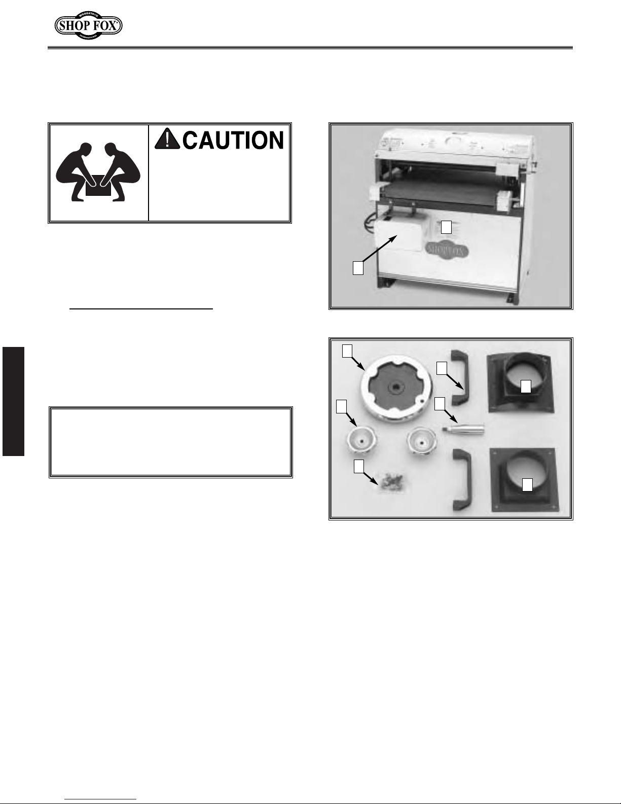
ASSEMBLY
Unpacking
Get moving assistance
before starting assembly.
The Model W1678 Double
Drum Sander is a heavy
load at 435 pounds.
The Model W1678 26" Double Drum Sander is
carefully packed. However, if it is damaged
or is missing any parts, please contact
Woodstock International Service and
Support at 1-360-734-3482 or send e-mail
to: tech-support@shopfox.biz
.
1
2
Figure 10. W1678 26" Double Drum Sander
Box Contents
Lay out and inventory the shipped parts to
familiarize yourself with your Model W1678 26"
Double Drum Sander. See Figures 10 and 11.
This will help with the machine assembly.
ASSEMBLY
Depending on manufacture date, some of the
box contents may already be installed on your
sander.
Item Qty.
1. W1678 26" Double Drum Sander 1
2. Control Box 1
3 Dust Port (Flat Base) 1
4. Dust Port (Concave Base) 1
5. Crank Wheel 1
6. Crank Handle 1
7. Hand Knob 2
8. Handle 2
9. Bolt and Wrench Bag: 1
• Self Tapping Screw (#8 X
• Flat Washer (#10) 8
• Cap Screw (
• Lock Washer (
• Hex Nut (
• Set Screw (
• Set Screw (
• Allen
• Allen
• Allen
NOTICE
1
⁄2") 8
5
⁄16"-18 X 1") 4
5
⁄16") 4
5
⁄16"-18) 4
5
⁄16"-18 X 1⁄2") 1
1
®
®
®
⁄4"-20 X 5⁄16") 2
Wrench (3 mm) 1
Wrench (4 mm) 1
Wrench (6 mm) 1
5
8
4
7
9
6
3
Figure 11. Components
-10-

Shop Preparation
Make sure shop entrances
are locked and machines
are equipped with safety
lock-out devices when
not in use. DO NOT allow
untrained people in your
shop! Otherwise, injury
or death can occur.
• Machine Mobility: If you need to move your
drum sander or other machinery to achieve
any of the following requirements,
Woodstock International Inc. offers a line of
SHOP FOX
sander, use the SHOP FOX
Duty Mobile Base (Model Number D2058)
and the SHOP FOX
(Model Number D2246).
• Double Drum Sander Location: Choose a
location where, if a workpiece should be
ejected, you or bystanders will not be
struck. Take all necessary safety
precautions.
®
Mobile Bases. For your drum
®
®
Super Heavy-
36" Extension Bars
Initial Cleaning
If the sander has any dust or slight stains from
shipping, DO NOT use a mineral-spirit solvent or
chlorine-based cleaner to clean any painted or
plastic surface, or the rubber conveyor belt. If you
do, you will permanently ruin the surface. Instead,
use a clean moist towel dampened with mild dish
soap and water to clean these surfaces.
If the sander has any grease spots which may
have fallen on metal parts from a drum bearing
during shipping, read and understand the
following Warnings and Cautions, and then use
mineral spirits to remove the excess grease.
Then coat the cleaned metal surface with a light
coat of machine oil to prevent corrosion.
Never use flammables
such as gas or other
petroleum-based solvents
to clean your machine.
These products have low
flash points and present
the risk of explosion and
severe personal injury!
ASSEMBLY
• Working Clearances: Consider your current
and future needs with respect to the size of
lumber to be processed at each machine,
space for auxiliary stands, work tables, and
other machinery.
• Lighting: Make sure your lighting eliminates
shadows and prevents eye strain.
• Outlets: Make sure electrical circuits are
dedicated or large enough to handle the
amperage requirements of the new
machinery. Electrical outlets should be
located near each machine so power or
extension cords are clear of high-traffic
areas.
Never smoke while using
cleaning solvents. Smoking
may cause explosion or
risk of fire when exposed
to these products!
Most solvents used to
clean machinery are
toxic when inhaled or
ingested. When using
these products, work in a
well ventilated area and
keep away from any
potential ignition sources
(pilot lights). Always
dispose of waste rags in a
sealed container to make
sure they do not cause
fire or environmental
hazards.
-11-

Beginning
Dust Port and
The main components of the Model W1678 are
assembled at the factory; however, some
assembly is required. We recommend the
following sequence in this section for assembly.
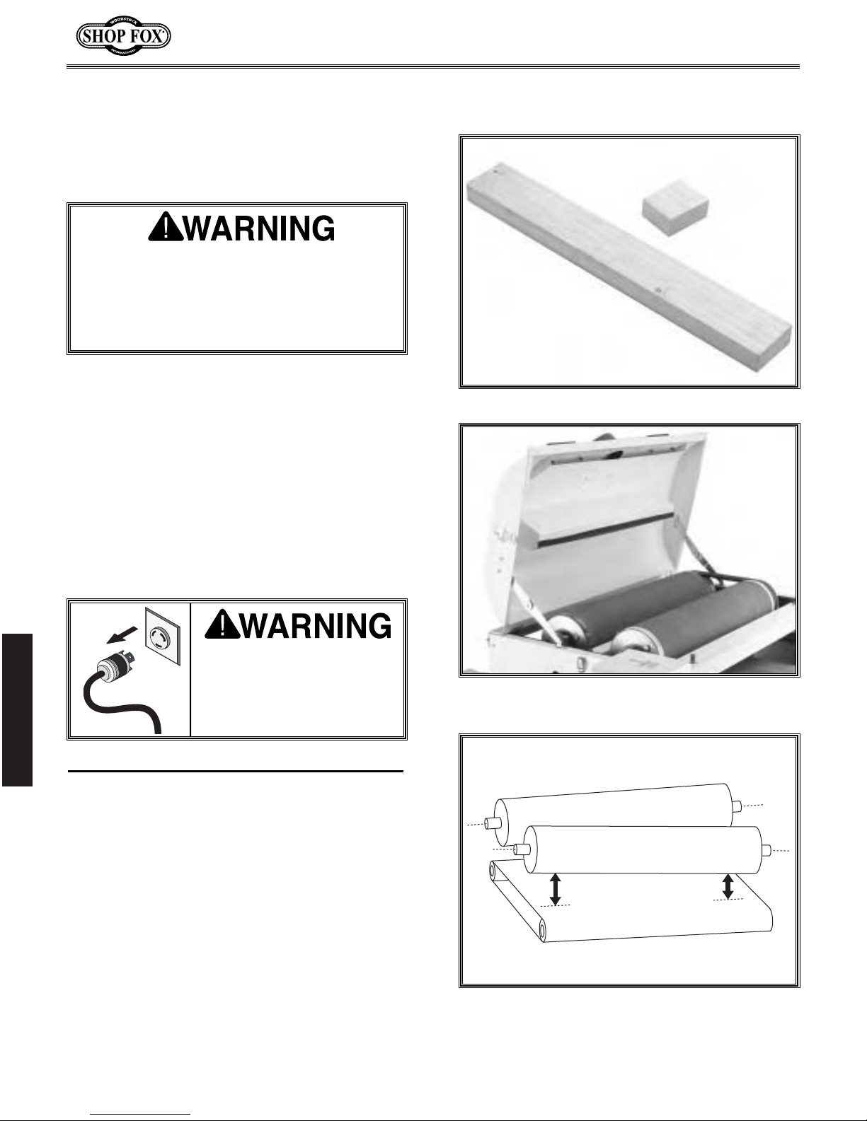
Keep your drum sander
unplugged during all
assembly, maintenance,
and adjustment tasks.
Ignoring this warning can
cause serious personal
injury to you or others!
Wear safety glasses during
assembly. Serious injury
may occur if this warning is
ignored!
Handles
When connected to a dust collection system, the
dust ports direct suction to remove harmful
wood and abrasive dust from the workpiece and
your work area.
DO NOT operate this
machine without the
correct dust collection
system. Failure to use a
dust collection system can
result in short and longterm respiratory illness.
Make sure the dust collection system draws at
least 600 CFM at the drum sander; however,
there will still be a normal layer of dust on the
workpiece when it exits the sander unless a
larger capacity dust collector is used.
ASSEMBLY
Figure 12. Dust ports and handles installed.
Get moving assistance
before starting assembly.
The Model W1678 Double
Drum Sander is a heavy
load at 435 pounds.
Make sure you connect flexible ducting to the
dust ports. This ducting allows you to open the
dust hood, change sandpaper, and service your
sander without having to disconnect the ducting.
For additional information on the correct dust
collection system, additions, or modifications;
contact your Woodstock International dealer for
your copy of the Dust Collection Basics
handbook and available accessories.
To install dust ports and handles, do these steps:
1. Position the dust ports on the dust hood so
the screw holes line up. See Figure 12.
2. With the dust ports held in position on the
dust hood, install the #10 flat washers on the
1
⁄2" self tapping screws and secure the dust
#8ports to the dust hood.
3. Connect your dust collection suction hose to
the dust ports, so when you open the dust
hood the suction hoses will not bind, leak, or
disconnect the dust-collector ducting ground.
4. Position the handles on the dust hood and
install the
washers, the
screws. See Figure 12.
-12-
5
⁄16"-18 x 1" cap screws, the 5⁄16" lock
5
⁄16" nuts, and tighten the cap
Short Bolts
Long Bolts
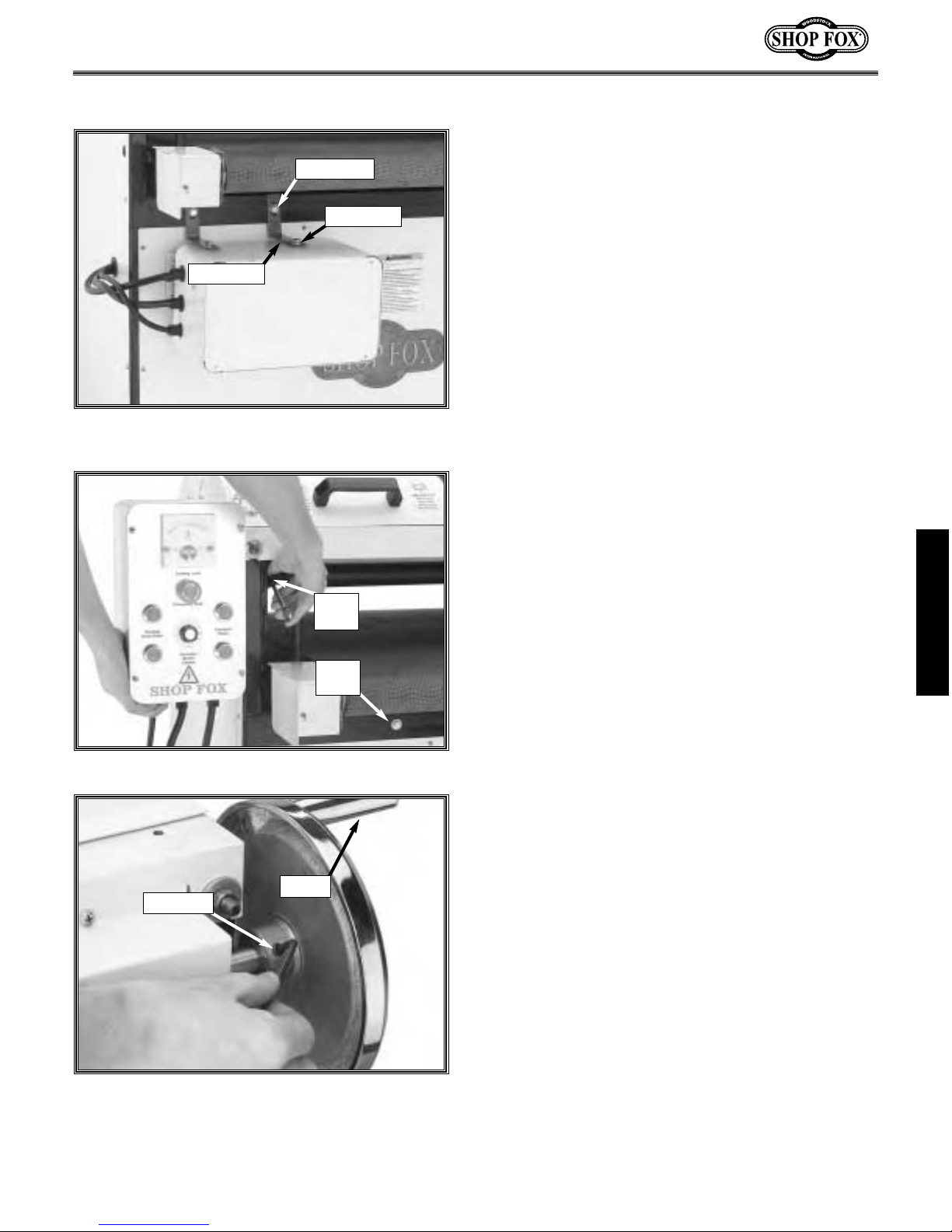
Control Box
The control panel allows you to control the
sander electrically. For shipping, the control box
comes bolted to the sander with L-brackets and
long and short bolts. Retain these brackets
should you ever need to ship the sander. See
Figure 13.
L-bracket
Figure 13. The control box, L-brackets, and
bolts for shipping.
Long
Bolt
Short
Bolt
To install the control box, do these steps:
1. Remove the L-brackets, bolts, and washers,
5
and reinstall the two short bolts (
1
⁄2") and washers into the sander. See Figure
⁄16"-18 x
14.
2. Position the control box on the sander, install
5
the flat washers and the
⁄16"-18 x 2" long
bolts.
3. Tighten the bolts. See Figure 14.
Crank and Handle
The crank and handle is used to raise and lower
the conveyor. For each revolution of the crank,
the conveyor moves 0.021".
To install the crank and handle, do these steps:
1. Thread the handle into the crank and use a
1
⁄2" wrench to tighten the handle to the crank.
ASSEMBLY
Figure 14. Short and long bolt locations.
Handle
Set Screw
Figure 15. The crank and handle installed.
2. Slide the handwheel onto the shaft and
align the threaded set screw bore on the
crank with the flat on the shaft.
5
3. Thread the
⁄16"-18 x 1⁄2" set screw into the
crank to secure the handwheel to the shaft.
See Figure 15.
®
4. Use the 4 mm Allen
wrench and tighten the
set screw.
-13-
ADJUSTMENTS
Drums and Pressure
Rollers
Adjust the sanding drums and pressure rollers
correctly. Complete PART 1, PART 2, PART 3,
and PART 4 of this section in sequence.
Otherwise, the sanding drums can grab and
project the workpiece damaging the sander,
and injuring you and bystanders!
To get the best sanding results and longest life
out of your sandpaper, both the front and rear
sanding drums must: (1) be square with the
conveyor table, (2) run parallel with each other
and parallel to the conveyor feed direction, and
(3) must be slightly staggered in height with one
another. Pressure-roller spring tension and height
must also be set correctly.
Figure 16. Gauge blocks for drum alignment.
As you become more familiar with your sander
you can vary your sander settings to fine-tune
the machine for your ultimate sanding goals.
ADJUSTMENTS
PART 1: Drum-to-Conveyor Squareness
For this adjustment, you will align the drums so the
drums are square with the feed conveyor belt
surface. See Figure 18.
To adjust the drum-to-conveyor squareness,
do these steps:
1. Make two gauge blocks from a quality piece
of straight two-by-four hardwood stud. One
block should be 30" long, and the other 2
long. See Figure 16.
Keep your drum sander
unplugged during these
adjustments. Otherwise,
serious personal injury
may occur!
5
Figure 17. W1678 dust hood open.
⁄8"
2. Unplug the Double Drum Sander!
3. Unlatch and open the dust hood. See Figure 17.
Figure 18. Drums to conveyor not square.
-14-
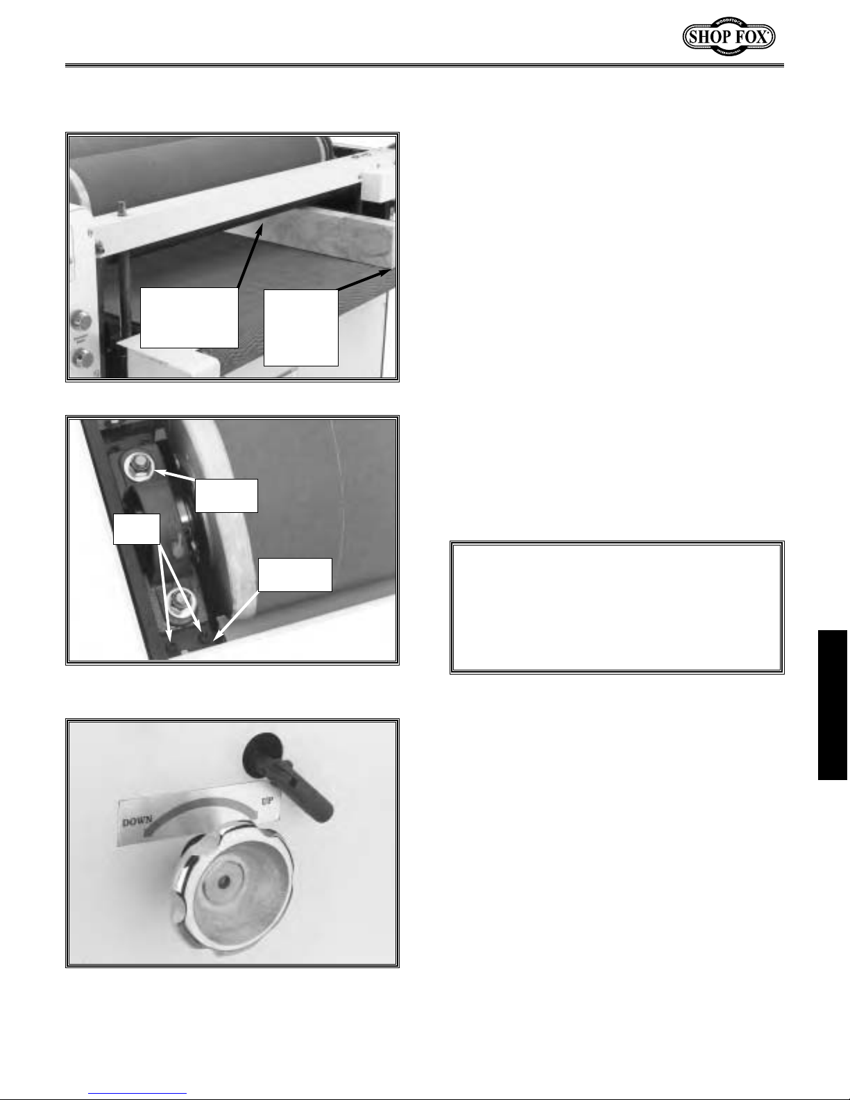
4. Lower the conveyor table and position the
30" gauge block under one end of the front
drum and flush with the end of the conveyor.
See Figure 19.
5. Turn the micro adjusting knob and raise the
rear drum so it will not contact the gauge
block.
Gauge Block
Barely Touching
the Underside
of Drum.
Gauge
Block End
Flush with
End of
Conveyor.
Figure 19. The 30" gauge block positioning.
Mounting
Nut
Set
Screws
Adjustment
Plate
Figure 20. Front bearing block, nuts, and set
screw tightening sequence.
6. Rotate the front drum by hand, and raise the
conveyor table until you hear the gauge block
barely rub the underside of the front drum.
7. Move the gauge block to the other side of the
conveyor table under the other end of the
front drum.
8. Rotate the drum again and listen and feel the
drag to determine which end of the drum is
too low or high.
9. At the low end of the drum, loosen the
1
bearing-block mounting nuts
⁄4 to1⁄3 turn.
See Figure 20.
NOTICE
DO NOT over-tighten the bearing block
mounting nuts. The bearing blocks are
machined housings that can warp or crack if
the nuts are over-tightened.
10.Use a 4 mm Allen
set screws at one end of each adjustment plate
1
⁄8" turn at a time to raise the bearing block
height at the low end of the drum. Remember,
adjusting one drum-end slightly affects the
adjustment at the opposite end. See Figure 20.
®
wrench to equally turn the
ADJUSTMENTS
Figure 21. Rear drum micro adjustment knob
and lock lever.
11.Repeat Steps 1 through 10 to achieve front
drum-to-conveyor squareness.
12.Tighten the nuts in an alternating pattern and
recheck the squareness.
13.Now use the 30" gauge block at the rear drum
to find which end is too low.
14.Unlock the micro-adjustment lock knob, and
turn the micro-adjust knob to adjust the rear
drum height. See Figure 21.Unlike the front
drum, there are no set screws to adjust the
rear drum height.
-15-
 Loading...