

Page 1

MODEL M1112 12" X 36"
GUNSMITHING LATHE
OWNER'S MANUAL
(FOR MODELS MANUFACTURED SINCE 1/15)
Phone: (360) 734-3482 • Online Technical Support: tech-support@shopfox.biz
COPYRIGHT © NOVEMBER 2007 BY WOODSTOCK INTERNATIONAL, INC., REVISED SEPTEMBER, 2017 (MN)
WARNING: NO PORTION OF THIS MANUAL MAY BE REPRODUCED IN ANY SHAPE OR FORM WITHOUT
#10091CR
THE WRITTEN APPROVAL OF WOODSTOCK INTERNATIONAL, INC.
Printed in China
Page 2

This manual provides critical safety instructions on the proper setup,
operation, maintenance, and service of this machine/tool. Save this
document, refer to it often, and use it to instruct other operators.
Failure to read, understand and follow the instructions in this manual
may result in fire or serious personal injury—including amputation,
electrocution, or death.
The owner of this machine/tool is solely responsible for its safe use.
This responsibility includes but is not limited to proper installation in
a safe environment, personnel training and usage authorization,
proper inspection and maintenance, manual availability and comprehension, application of safety devices, cutting/sanding/grinding tool
integrity, and the usage of personal protective equipment.
The manufacturer will not be held liable for injury or property
damage from negligence, improper training, machine modifications or
misuse.
Some dust created by power sanding, sawing, grinding, drilling, and
other construction activities contains chemicals known to the State of
California to cause cancer, birth defects or other reproductive harm.
Some examples of these chemicals are:
• Lead from lead-based paints.
• Crystalline silica from bricks, cement and other masonry products.
• Arsenic and chromium from chemically-treated lumber.
Your risk from these exposures varies, depending on how often you
do this type of work. To reduce your exposure to these chemicals:
Work in a well ventilated area, and work with approved safety equipment, such as those dust masks that are specially designed to filter
out microscopic particles.
Page 3

Table of Contents
INTRODUCTION .....................................2
Woodstock Technical Support .................. 2
Controls and Features ........................... 6
SAFETY ............................................... 7
Standard Safety Instructions ................... 7
Additional Safety Instructions for Lathes .... 9
Avoiding Potential Injuries .................... 10
ELECTRICAL ....................................... 11
Circuit Requirements .......................... 11
Grounding Requirements ...................... 12
Extension Cords ................................ 12
SET UP .............................................. 13
Inventory ........................................ 13
Uncrating and Lifting .......................... 14
Cleaning Machine ............................... 15
Machine Placement ............................ 15
Mounting to Shop Floor ........................ 16
Power Connection .............................. 16
Test Run & Break-In ............................ 17
Tailstock ......................................... 19
OPERATIONS....................................... 21
General .......................................... 21
Spindle Speeds .................................. 21
Mounting Chuck or Faceplate ................ 22
Swapping Jaws .................................. 25
Four-Jaw Chuck ................................ 26
Faceplate ........................................ 27
Centers........................................... 28
Spindle Spider .................................. 28
Steady Rest ...................................... 29
Follow Rest ...................................... 29
Feed Direction Lever .......................... 30
Feed Rod Lever ................................. 30
Gearbox Levers ................................. 31
Feed Rate Chart ................................ 31
Carriage/Cross Feed Lever ................... 32
Half-Nut Lever and Inch Threading.......... 32
Change Gears & Metric Threading ........... 33
Carriage Handwheels .......................... 35
Tool Post & Holder ............................. 35
Tailstock ......................................... 36
Cutting Shallow Tapers with Tailstock ...... 37
Drilling with Tailstock ......................... 37
Gap Piece Removal............................. 38
Model M1112 Lathe Accessories .............. 39
MAINTENANCE .................................... 40
General Maintenance .......................... 40
General Cleaning ............................... 40
General Lubrication ............................ 40
Coolant System ................................. 42
SERVICE ............................................ 43
Troubleshooting ................................. 43
Troubleshooting ................................. 44
Gibs ............................................... 45
Half-Nut Adjustment ........................... 46
Adjusting/Replacing V-Belts .................. 47
Spindle Bearing Preload ....................... 48
M1112 Main Electrical Box Wiring Diagram 51
Headstock Shifters and Change Gears ...... 58
PARTS .............................................. 59
Headstock Gearing and Control Panel ..... 60
Quick Change Gearbox ........................ 62
Apron Assembly ................................. 64
Saddle and Cross Feed ........................ 66
Compound Rest ................................. 68
Tailstock Assembly ............................. 69
Bed and Motor Parts ........................... 70
Cabinet Parts ................................... 71
Spindle Switch Control Rod Assembly ....... 73
Coolant System and Lamp .................... 74
Lathe Accessories .............................. 75
Main Electrical Box ............................ 76
Follow Rest and Steady Rest ................. 77
Label Placement ............................... 78
WARRANTY ........................................ 81
SAFETYINTRODUCTION
SETUPELECTRICAL MAINTENANCE
OPERATIONS
SERVICE PARTS
USE THE QUICK GUIDE PAGE LABELS TO SEARCH OUT INFORMATION FAST!
Page 4

M1112 12" x 36" Gunsmithing Lathe (Mfg. Since 4/08)
INTRODUCTION
INTRODUCTION
Woodstock Technical Support
Your new SHOP FOX® Model M1112 Lathe has been specially designed to provide many years of troublefree service. Close attention to detail, ruggedly built parts and a rigid quality control program assure
safe and reliable operation.
Woodstock International, Inc. is committed to customer satisfaction. Our intent with this manual is to
include the basic information for safety, set up, operation, maintenance, and service of this product.
We stand behind our machines! In the event that questions arise about your machine, please contact
Woodstock International Technical Support at (360) 734-3482 or send e-mail to: tech-support@shopfox.
biz. Our knowledgeable staff will help you troubleshoot problems and process warranty claims.
If you need the latest edition of this manual, you can download it from http://www.shopfox.biz.
If you have comments about this manual, please contact us at:
Woodstock International, Inc.
Attn: Technical Documentation Manager
P.O. Box 2309
Bellingham, WA 98227
Email: manuals@woodstockint.com
-2-
Page 5

M1112 12" x 36" Gunsmithing Lathe (Mfg. Since 4/08)
MODEL M1112
GUNSMITH LATHE WITH STAND
Product Dimensions
Weight........................................................................................................ 1213 lbs.
Width (side‐to‐side) x Depth (front‐to‐back) x Height................................... 61 x 26 x 54‐1/2 in.
Footprint (Length x Width).................................................................... 57‐1/2 x 14‐1/2 in.
Shipping Dimensions
Carton #1
Type................................................................................................ Wood Crate
Content................................................................................................. Machine
Weight................................................................................................. 1050 lbs.
Length x Width x Height..................................................................... 66 x 30 x 29 in.
Carton #2
Type............................................................................................. Cardboard Box
Content.............................................................................................. Left Stand
Weight................................................................................................... 108 lbs.
Length x Width x Height..................................................................... 15 x 15 x 15 in.
Carton #3
Type............................................................................................. Cardboard Box
Content............................................................................................. Right Stand
Weight.................................................................................................... 93 lbs.
Length x Width x Height..................................................................... 15 x 15 x 15 in.
Electrical
Power Requirement.................................................................... 220V, Single‐Phase, 60 Hz
Prewired Voltage................................................................................................. 220V
Full‐Load Current Rating......................................................................................... 12A
Minimum Circuit Size............................................................................................. 15A
Connection Type......................................................................................... Cord & Plug
Power Cord Included............................................................................................... No
Recommended Power Cord............................................... “S”‐Type, 3‐Wire, 14 AWG, 300 VAC
Plug Included........................................................................................................ No
Recommended Plug Type........................................................................................ 6‐15
Switch Type....................................................... Control Panel w/Magnetic Switch Protection
INTRODUCTION
Motors
Main
Horsepower................................................................................................. 2 HP
Phase.............................................................................................. Single‐Phase
Amps.......................................................................................................... 12A
Speed.................................................................................................. 1725 RPM
Type......................................................................... TEFC Capacitor‐Start Induction
Power Transfer ............................................................................ Twin V‐Belt Drive
Bearings............................................................... Shielded & Permanently Lubricated
-3-
Page 6

INTRODUCTION
M1112 12" x 36" Gunsmithing Lathe (Mfg. Since 4/08)
Main Specifications
Operation Info
Swing Over Bed........................................................................................... 12 in.
Distance Between Centers.............................................................................. 36 in.
Swing Over Cross Slide.................................................................................... 7 in.
Swing Over Saddle............................................................................... 11‐11/32 in.
Swing Over Gap........................................................................................... 17 in.
Maximum Tool Bit Size................................................................................. 5/8 in.
Compound Travel..................................................................................... 3‐1/4 in.
Carriage Travel........................................................................................... 24 in.
Cross Slide Travel.................................................................................... 6‐1/4 in.
Headstock Info
Spindle Bore............................................................................................ 1.57 in.
Spindle Taper.............................................................................................. MT#5
Number of Spindle Speeds................................................................................... 9
Spindle Speeds................................................................................. 70 – 1400 RPM
Spindle Type.................................................................................... D1‐5 Camlock
Spindle Bearings............................................................ High‐Precision Tapered Roller
Spindle Length with Faceplate................................................................... 18‐1/2 in.
Tailstock Info
Tailstock Quill Travel..................................................................................... 4 in.
Tailstock Taper........................................................................................... MT#3
Tailstock Barrel Diameter........................................................................... 1.563 in.
Threading Info
Number of Longitudinal Feeds............................................................................. 40
Range of Longitudinal Feeds..................................................... 0.0011 – 0.0310 in./rev.
Number of Cross Feeds...................................................................................... 40
Range of Cross Feeds............................................................... 0.0004 – 0.0105 in./rev
Number of Inch Threads..................................................................................... 40
Range of Inch Threads............................................................................. 4 – 112 TPI
Number of Metric Threads.................................................................................. 29
Range of Metric Threads....................................................................... 0.2 – 4.5 mm
Dimensions
Bed Width............................................................................................. 7‐1/4 in.
Carriage Leadscrew Diameter...................................................................... 0.870 in.
Leadscrew TPI............................................................................................. 8 TPI
Carriage Leadscrew Length............................................................................. 44 in.
Steady Rest Capacity............................................................................. 3/16 – 2 in.
Follow Rest Capacity............................................................................... 1/4 – 1 in.
Faceplate Size............................................................................................ 10 in.
Feed Rod Diameter..................................................................................... 3/4 in.
Floor to Center Height............................................................................. 46‐1/4 in.
Height With Leveling Jacks........................................................................ 48‐1/4 in.
-4-
Page 7

M1112 12" x 36" Gunsmithing Lathe (Mfg. Since 4/08)
Construction
Base.................................................................................................... Cast Iron
Headstock............................................................................................. Cast Iron
End Gears.............................................................................. Flame Hardened Steel
Bed.............................................................. Hardened and Precision‐Ground Cast Iron
Body.................................................................................................... Cast Iron
Stand....................................................................................... Cast Iron and Steel
Paint Type/Finish........................................................................................ Epoxy
Fluid Capacities
Headstock Capacity.................................................................................... 3.5 qt.
Headstock Fluid Type..................................... ISO 32 (eg. Grizzly T23963, Mobil DTE Light)
Gearbox Capacity................................................................................. 1 – 2 Pumps
Gearbox Fluid Type......................................... ISO 68 (eg. Grizzly T23962, Mobil Vactra 2)
Apron Capacity.......................................................................................... 0.5 qt.
Apron Fluid Type...................................... ISO 68 (SB1365, Grizzly T23962, Mobil Vactra 2)
Other
Country of Origin ............................................................................................... China
Warranty ....................................................................................................... 2 Years
Approximate Assembly & Setup Time ..................................................................... 2 Hours
Serial Number Location ................................................................... ID Label on Headstock
ISO 9001 Factory ................................................................................................... No
Certified by a Nationally Recognized Testing Laboratory (NRTL) .......................................... No
INTRODUCTION
Features
Removable Gap Bed Allows Turnings up to 17" in Diameter
Easy to Use Lever Controls
Full Length Splash Guard
On/Off Reverse Switch on Carriage
Halogen Work Light
Ball Bearing Steady/Follow Rests
Outboard End Support Screws
Socket for Tailstock Lock
Steel Stand with Extended Base
Cast Aluminum Gear Cover
Nine Spindle Speeds, Ranging from 70 to 1400 RPM
Accessories
1 MT#3 Live Center
1/2" Chuck with MT#3 Arbor
10" Face Plate
2 MT#3 Dead Centers (1 Carbide Tipped)
6" 3‐Jaw Chuck with 2 Sets of Jaws
8" 4‐Jaw Chuck with Reversible Jaws
Follow Rest with Roller Tips
Quick Change Tool Post with One Tool Holder
Set of Six Change Gears
Steady Rest with Roller Tips
Tool Box
-5-
Page 8
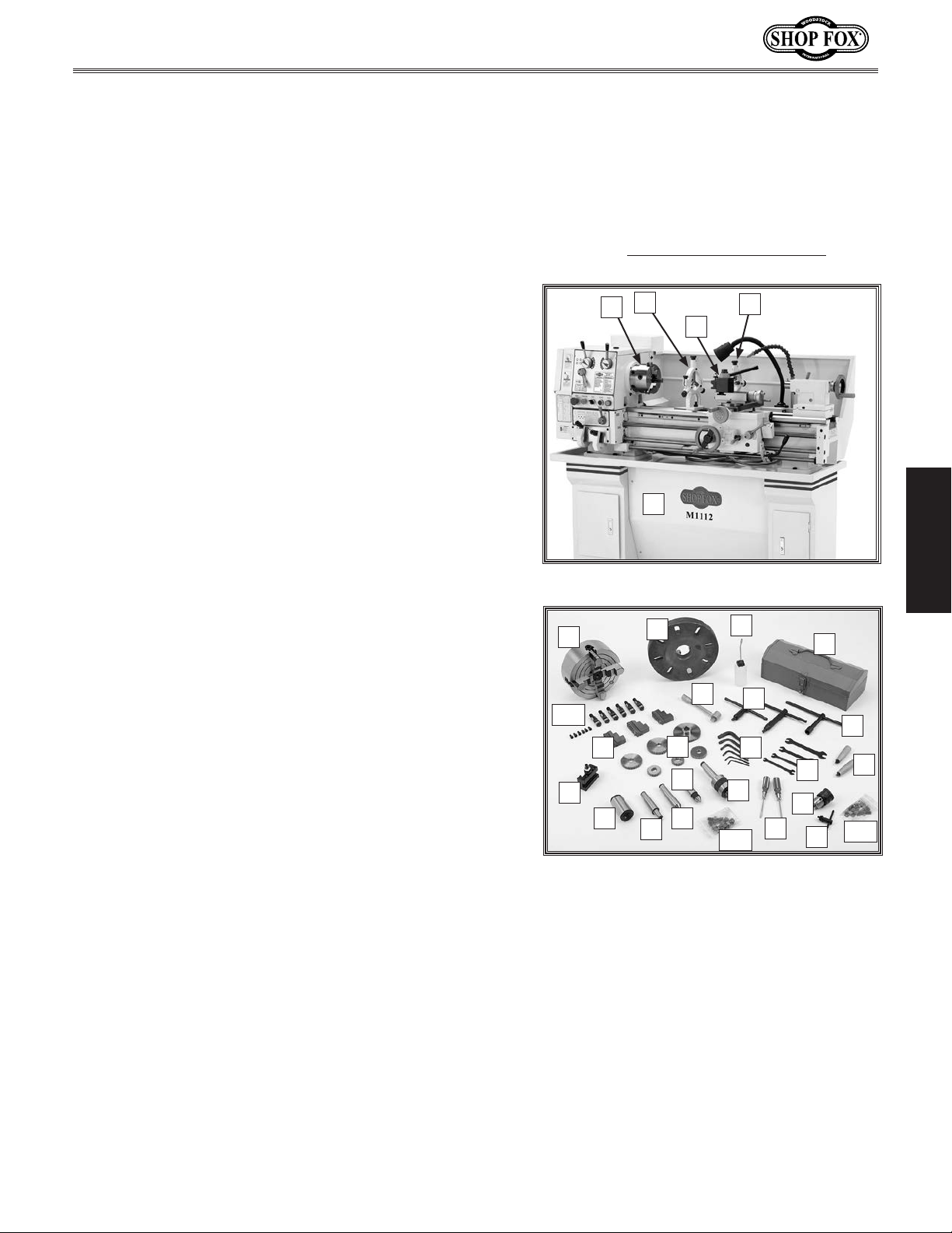
INTRODUCTION
M1112 12" x 36" Gunsmithing Lathe (Mfg. Since 4/08)
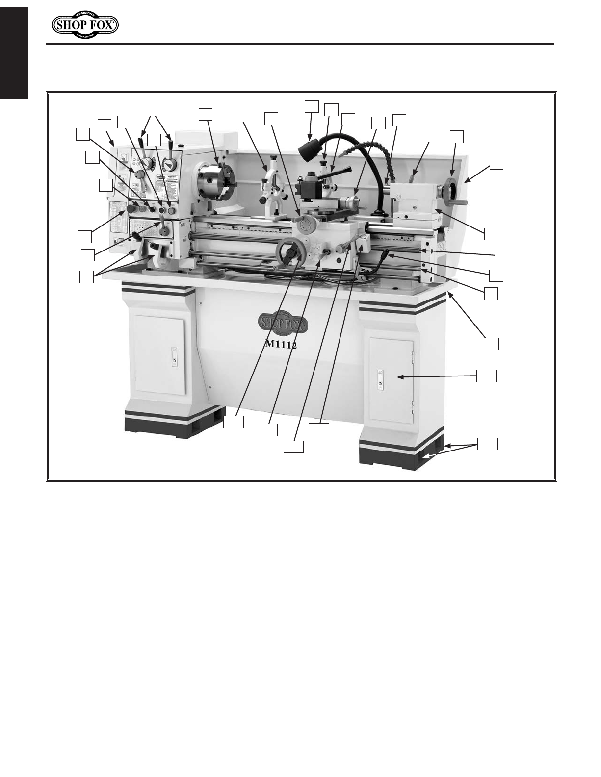
Controls and Features
N
J
H
G
F
I
K
L
M
O
P
R
Q
S
T
E
D
C
B
A
FF
EE
CC
DD
U
V
W
X
Y
Z
AA
BB
A. Quick Change Gearbox Levers
B. Feed Rod Lever
C. Emergency Stop/RESET Button
D. POWER START Button
E. Pump Switch
F. Feed Direction Lever
G. Gear and Belt Cover
H. Inching/Jog Button
I. Power Light
J. Spindle Speed Levers
K. 3-Jaw Chuck
L. Steady Rest
M. Cross Feed Handwheel
N. Halogen Work Light
O. Follow Rest
P. Tool Rest
Model M1112 lathe.
Q. Compound Rest Handwheel
R. Tailstock Spindle and Center
S. Tailstock Spindle Lock Lever
T. Tailstock Spindle Handwheel
U. Back Splash Guard
V. Tailstock
W. Leadscrew
X. Spindle Rotation ON/OFF Lever
Y. Feed Rod
Z. Chip Tray
AA. Storage Cabinet
BB. Stand Mounting Points
CC. Thread Dial
DD. Half-nut Lever
EE. Apron/Cross Feed Lever
FF. Carriage Handwheel
-6-
Page 9

M1112 12" x 36" Gunsmithing Lathe (Mfg. Since 4/08)
SAFETY
READ MANUAL BEFORE OPERATING MACHINE.
FAILURE TO FOLLOW INSTRUCTIONS BELOW WILL
RESULT IN PERSONAL INJURY.
Indicates an imminently hazardous situation which, if not avoided, WILL
result in death or serious injury.
Indicates a potentially hazardous situation which, if not avoided, COULD
result in death or serious injury.
Indicates a potentially hazardous situation which, if not avoided, MAY
result in minor or moderate injury.
This symbol is used to alert the user to useful information about proper
NOTICE
operation of the equipment, and/or a situation that may cause damage
to the machinery.
Standard Safety Instructions
SAFETY
1. Thoroughly read the Instruction Manual before operating your machine. Learn the applications,
limitations and potential hazards of this machine. Keep the manual in a safe and convenient place
for future reference.
2. Keep work area clean and well lighted. Clutter and inadequate lighting invite potential hazards.
3. Ground all tools. If a machine is equipped with a three-prong plug, it must be plugged into a
three-hole grounded electrical receptacle or grounded extension cord. If using an adapter to aid in
accommodating a two-hole receptacle, ground using a screw to a known ground.
4. Wear eye protection at all times. Use safety goggles with side shields or safety goggles that meet
the appropriate standards of the American National Standards Institute (ANSI).
5. Avoid dangerous environments. Do not operate this machine in wet or open flame environments.
Airborne dust particles could cause an explosion and severe fire hazard.
6. Ensure all guards are securely in place and in working condition.
7. Make sure switch is in the OFF position before connecting power to machine.
8. Keep work area clean, free of clutter, grease, etc.
9. Keep children and visitors away. Visitors must be kept at a safe distance while operating unit.
10. Childproof your workshop with padlocks, master switches or by removing starter keys.
11. Stop and disconnect the machine when cleaning, adjusting or servicing.
-7-
Page 10

M1112 12" x 36" Gunsmithing Lathe (Mfg. Since 4/08)
12. Do not force tool. The machine will do a safer and better job at the rate for which it was
designed.
13. Use correct tool. Do not force machine or attachment to do a job for which it was not designed.
14. Wear proper apparel. Do not wear loose clothing, neck ties, gloves, jewelry, and secure long hair
away from moving parts.
15. Remove chuck keys, rags, and tools. Before turning the machine on, make it a habit to check
SAFETY
that all chuck keys and wrenches have been removed.
16. Keep proper footing and balance at all times.
17. Lock the mobile base from moving before feeding the workpiece into the machine.
18. Do not leave machine unattended. Wait until it comes to a complete stop before leaving the
area.
19. Perform machine maintenance and care. Follow lubrication and accessory attachment
instructions in the manual.
20. Keep machine away from open flame. Operating machines near pilot lights or open flames
creates a high risk if dust is dispersed in the area. Dust particles and an ignition source may cause
an explosion. Do not operate the machine in high-risk areas, including but not limited to, those
mentioned above.
21. If at any time you are experiencing difficulties performing the intended operation, stop using the
machine! Then contact our technical support or ask a qualified expert how the operation should be
performed.
22. Be aware that certain materials may cause an allergic reaction in people and animals,
especially when exposed to fine dust. Make sure you know what type of material dust you will be
exposed to and the possibility of an allergic reaction.
23. Habits—good and bad—are hard to break. Develop good habits in your shop and safety will
become second-nature to you.
-8-
Page 11
M1112 12" x 36" Gunsmithing Lathe (Mfg. Since 4/08)
Additional Safety Instructions for Lathes
READ and understand this
entire instruction manual
before using this machine.
Serious personal injury
may occur if safety and
operational information is
not understood and followed. DO NOT risk your
safety by not reading!
1. AVOIDING INJURY: Read and understand this manual before operating this machine.
2. SAFE CLEANING: Do not clear chips by hand. Use a brush to avoid lacerations, and never clear
chips while the lathe is turning, or entanglement may occur.
3. USING CORRECT TOOLING: Always select the right tool bit for the job, and make sure cutting
edges are sharp. Dull or incorrect bits can break and become a projectile causing severe injury.
4. USING CHUCK KEY CORRECTLY: Never walk away from the lathe with the key in the chuck. An
accidental start can throw the chuck key with great velocity causing severe injury.
5. SECURING A WORKPIECE: Make sure workpiece is properly held in chuck before starting lathe. A
workpiece thrown from the chuck will cause severe injury.
USE this and other machinery with caution
and respect. Always consider safety first,
as it applies to your individual working
conditions. No list of safety guidelines can
be complete—every shop environment is
different. Failure to follow guidelines could
result in serious personal injury, damage
to equipment or poor work results.
SAFETY
6. CHUCK SAFETY: Get assistance when installing large chucks. Large lathe chucks are very heavy
and awkward to hold and may cause injury from dropping or lifting incorrectly, so protect your
hands and the precision ground ways. Always use a chuck cradle or piece of plywood over the bed
and ways to prevent accidental damage.
7. WORKPIECE SUPPORT: Support a long workpiece if it extends from the headstock so it will not wobble violently when the lathe is turned on. A workpiece that extends more than 2.5 times its diameter
must be supported by a center or steady rest or it may be thrown from the lathe.
8. AVOIDING STARTUP INJURIES: Make sure workpiece, cutting tool, and tool post have adequate
clearance before starting lathe. Check chuck clearance and saddle clearance before starting the
lathe. Make sure spindle RPM is set correctly for part diameter before starting the lathe. Large
parts can be ejected from the chuck if the chuck speed is set too high.
9. AVOIDING OVERLOADS: Always use the appropriate feed and speed rates. Otherwise you may
break tooling or eject a workpiece causing severe injury.
10. AVOIDING ENTANGLEMENT INJURIES: Never attempt to slow or stop the lathe chuck by hand, and
tie back long hair, ponytails, loose clothing, and sleeves so they do not dangle.
11. MAINTAINING A SAFE WORKPLACE: Never leave lathe unattended while it is running, or coworkers
or passers by may be injured severely.
12. PREVENTING LATHE CRASHES: Disengage the automatic feed levers after completing a job.
-9-
Page 12
M1112 12" x 36" Gunsmithing Lathe (Mfg. Since 4/08)
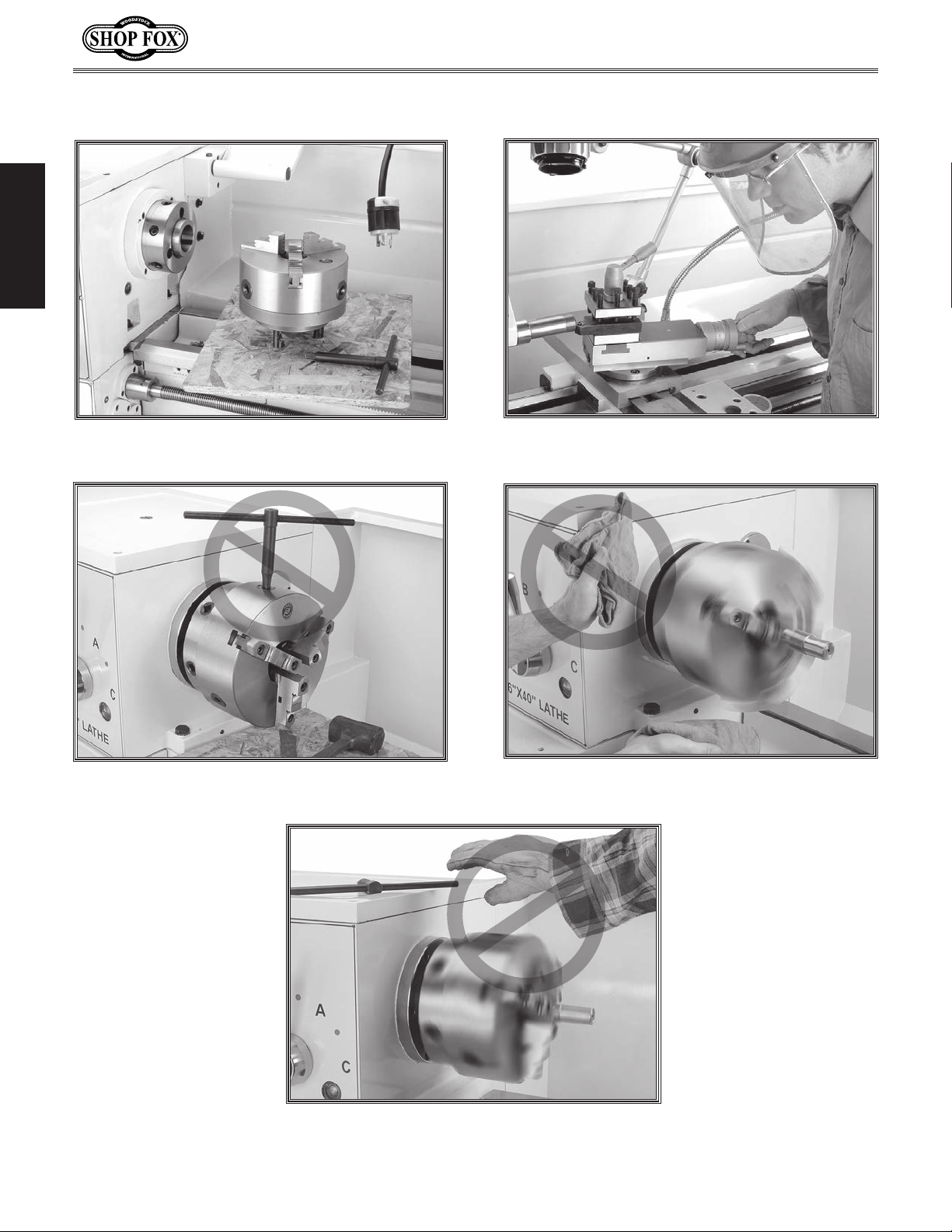
Avoiding Potential Injuries
SAFETY
Figure 1. Always protect the bed ways, and
unplug the lathe when retooling the lathe.
Figure 2. Never walk away from the lathe with
the chuck key inserted in the chuck.
Figure 3. Always wear face and eye protection
when using lathes.
Figure 4. Never use hands to stop or slow the
chuck when shutting down the lathe.
Figure 5. Never wear loose clothing or gloves
when working with the lathe.
-10-
Page 13
M1112 12" x 36" Gunsmithing Lathe (Mfg. Since 4/08)
This machine must be connected to the correct size and
type of power supply circuit, or fire or electrical damage
may occur. Read through this section to determine if an
adequate power supply circuit is available. If a correct
circuit is not available, a qualified electrician MUST install
one before you can connect the machine to power.
A power supply circuit includes all electrical equipment
between the breaker box or fuse panel in the building
and the machine. The power supply circuit used for
this machine must be sized to safely handle the fullload current drawn from the machine for an extended
period of time. (If this machine is connected to a circuit
protected by fuses, use a time delay fuse marked D.)
This machine is prewired to operate on a 220V power
supply circuit that has a verified ground and meets the
following requirements:
The full-load current rating is the amperage a machine
draws at 100% of the rated output power. On machines
with multiple motors, this is the amperage drawn by the
largest motor or sum of all motors and electrical devices
that might operate at one time during normal operations.
or machine damage. To reduce this risk,
where only one machine will be running
ELECTRICAL
Circuit Requirements
The machine must be properly set up
before it is safe to operate. DO NOT
connect this machine to the power
source until instructed to do later in
this manual.
ELECTRICAL
Full-Load Current Rating
Full-Load Current Rating at 220V .................. 12 Amps
Circuit Requirements for 220V
Circuit Ty p e ...............220V/240V, 60 Hz, Single-Phase
Circuit Size ............................................. 15 Amps
Plug/Receptacle .................................... NE M A 6 -15
Cord .................“S”-Type, 3-Wire, 14 AWG, 300 VAC
Incorrectly wiring or grounding this
machine can cause electrocution, fire,
only an electrician or qualified service
personnel should do any required
electrical work on this machine.
NOTICE
The circuit requirements listed in this
manual apply to a dedicated circuit—
at a time. If this machine will be
connected to a shared circuit where
multiple machines will be running at
the same time, consult a qualified
electrician to ensure that the circuit is
properly sized for safe operation.
-11-
Page 14
M1112 12" x 36" Gunsmithing Lathe (Mfg. Since 4/08)
This machine MUST be grounded. In the event of certain
types of
a path of least resistance for electric current
order
Improper connection of the equipment-grounding
will
increase
insulation
grounding
cord or plug is necessary, do not connect the equipmentgrounding
Check with a qualified electrician or service personnel
if
or if
properly grounded.
plug is damaged or worn, disconnect it from power, and
immediately replace it with a new one.
We do not recommend using an extension cord with
Any extension cord used with this machine must contain a
plug and receptacle, and
meet the following requirements:
receptacle. Instead, have a qualified
Grounding Requirements
malfunctions or breakdowns, grounding provides
to travel—in
to reduce the risk of electric shock.
wire
the risk of electric shock. The wire with green
(with/without yellow stripes) is the equipment-
wire. If repair or replacement of the power
wire to a live (current carrying) terminal.
you do not understand these grounding requirements,
ELECTRICAL
you are in doubt about whether the tool is
If you ever notice that a cord or
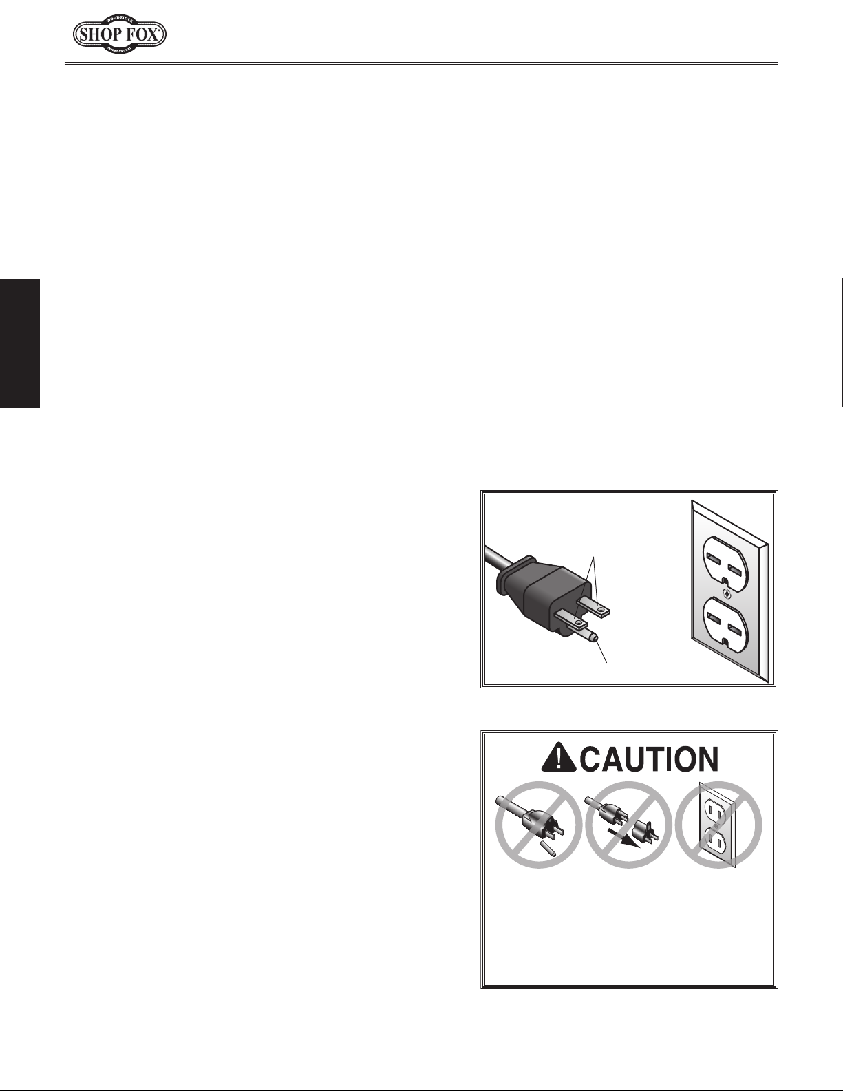
For 220V Connection
The power cord and plug specified under "Circuit
Requirements for 220V" on the previous page has an
equipment-grounding wire and a grounding prong. The
plug must only be inserted into a matching receptacle
(outlet) that is properly installed and grounded in
accordance with all local codes and ordinances (see figure
to the right).
Extension Cords
this machine. Extension cords cause voltage drop, which
may damage electrical components and shorten motor
life. Voltage drop increases with longer extension cords
and smaller gauge sizes (higher gauge numbers indicate
smaller sizes).
ground wire
Minimum Gauge Size at 220V ...................... 14 AWG
Maximum Length (Shorter is Better) ................ 50 ft.
, match the required
-12-
220V
Current Carrying Prongs
6-15 PLUG
Figure 6. NEMA 6-15 plug & receptacle.
DO NOT modify the provided plug or use
an adapter if the plug will not fit your
electrician install the proper receptacle
on a power supply circuit that meets the
requirements for this machine.
GROUNDED
6-15 RECEPTACLE
Grounding Prong
Page 15
M1112 12" x 36" Gunsmithing Lathe (Mfg. Since 4/08)
SET UP
Inventory
Main Components (Figure 7) Qty
A. 6" Three-Jaw Chuck w/Jaws .............................1
B. Steady Rest .................................................1
C. Follow Rest .................................................1
D. Quick Change Tool Post ...................................1
E. Cabinet Base:
—Cabinets (Left & Right) .................................2
—Front Panel ...............................................1
—Front Panel Brackets ....................................2
Accessory Components (Figure 8)
F. 8" Four-Jaw Universal Chuck ............................1
G. 10" Faceplate...............................................1
H. Oil Bottle ...................................................1
I. Tool Box .....................................................1
J. Three-Jaw Chuck Jaws ...................................3
K. Tailstock Wrench ...........................................1
L. 3- and 4-Jaw Chuck Wrenches .......................1 EA
M. Square Socket T-Wrench ..................................1
N. Quick Change Tool Holder ................................1
O. Change Gears ..............................................1
—Gear 27-Tooth ............................................1
—Gear 26-Tooth ............................................1
—Gear 35-Tooth ............................................1
—Gear 40-Tooth (Installed) ..............................2
—Gear 45-Tooth ............................................1
—Gear 50-Tooth ............................................1
—Gear 60-Tooth ............................................1
—Gear 86/91-Tooth (Installed) ..........................1
P. Hex Wrench Set 2, 4, 5, 6, 8, 10 mm ..............1 EA
Q. Wrenches 9/11, 10/12, 12/14, 17/19mm .........1 EA
R. Handwheel Handles .......................................2
S. Dead Center Spindle Sleeve .............................1
T. Arbor B16 to MT#3 ........................................1
U. Standard Dead Center MT#3 .............................1
V. Carbide Tipped Dead Center MT#3 .....................1
W. Live Center MT#3 ................................ ..........1
X. #2 Phillips & Standard Screwdrivers ................1 EA
Y. Drill Chuck B16 1.5-13mm ...............................1
Z. Drill Chuck Key .............................................1
AA. Spider Screws ..............................................4
BB. Camlock Stud Kit ..........................................1
CC. Cabinet Base Fasteners:
—Hex Bolts M12-1.75 x 40 ................................6
—Flat Washers 12mm .....................................6
—Phillips Head Screws M6-1 x 10 ..................... 12
—Hex Nuts M6-1 ............................................4
—Flat Washers 6mm ..................................... 12
If any parts are missing, find the part number in the back of this manual and contact
Woodstock International, Inc. at (360) 7343482 or at tech-support@shopfox.biz
B
A
D
E
Figure 7. Main contents.
F
BB
J
N
S
Figure 8. Packaged components.
G
K
O
U
V
T
W
AA
C
H
I
L
M
P
Q
Y
X
R
CC
Z
SETUP
-13-
Page 16
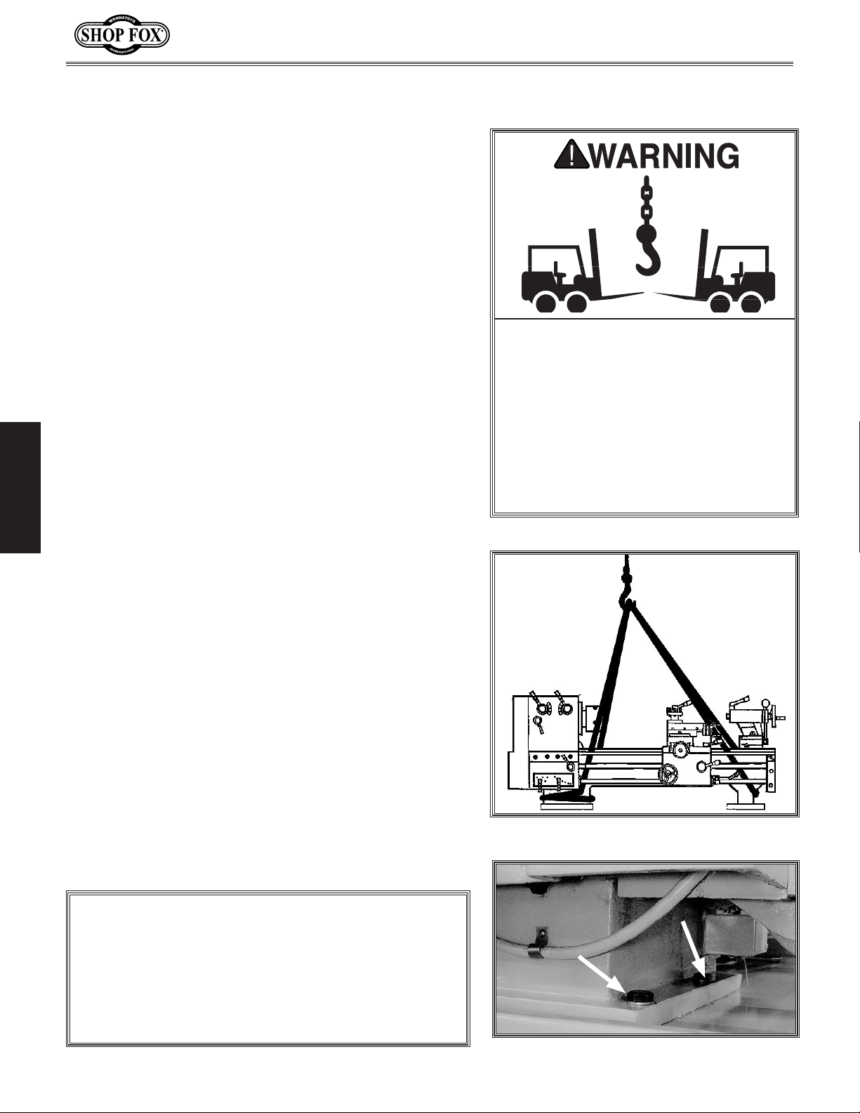
Uncrating and Lifting
The Model M1112 lathe has been carefully crated. If
you notice the lathe has been damaged, contact your
authorized
To lift and move the lathe, do these steps:
1. Wrap two lifting straps around the bedway pedestals
and route them behind the feed rod, control rod, and
the lead screw, as shown in Figure 9.
2. Move the apron toward the right to help balance the
load, as shown in Figure 9.
3. Position the chip pan on top of the base assembly so
that the six lathe mounting holes align with top holes
of the cabinets.
4. Un-bolt the lathe from the pallet.
5. Slowly raise the lathe from the pallet, and move it
over the cabinet base to your prepared location.
SHOP FOX
SETUP
6. Position the lathe so that the six M12-1.75 x 40
hex bolts and flat washers can be inserted through
the chip pan and partially threaded, but not fully
tightened, into the mounting holes of the cabinets
(see Figure 10).
®
dealer immediately.
M1112 12" x 36" Gunsmithing Lathe (Mfg. Since 4/08)
The Model M1112 weighs approximately
1400 lbs. You will need power lifting
equipment and assistance to remove
this machine from the crate and position it. Inspect all lifting equipment
and make sure that all is in perfect
working order and is rated for the load
before attempting to lift and move this
lathe. Ignoring this warning may lead to
serious personal injury or death.
7. Shim between the lathe and cabinet base as required
to make the ways level at all four corner locations as
indicated with a machinist's level.
8. Fully tighten the six hex bolts to secure the lathe to
the cabinet base.
9. For best results, recheck the ways in 24 hours to
make sure the ways are still level and have not
twisted, and re-shim as required.
10. Install the backsplash with four M6-1 x 10 Phillips
head screws and flat washers.
NOTICE
If a lathe is not level, the ways can twist out of
alignment, and cutting operations may be affected.
Make sure that your level is a high-quality machinist's
level, and that all measuring surfaces are perfectly
clean. Recheck the lathe ways in a few weeks to make
sure the floor has not settled. Re-shim as required.
Figure 9. Lifting strap locations.
Figure 10. Lathe mounting hex bolts.
-14-
Page 17
M1112 12" x 36" Gunsmithing Lathe (Mfg. Since 4/08)
Cleaning Machine
The ways and other unpainted parts of your lathe are
coated with a waxy grease that protects them from
corrosion during shipment. Clean this grease off with a
solvent cleaner or citrus-based degreaser. DO NOT use
chlorine-based solvents such as brake parts cleaner,
lacquer thinner, or acetone—if you happen to splash some
onto a painted surface, you will ruin the finish.
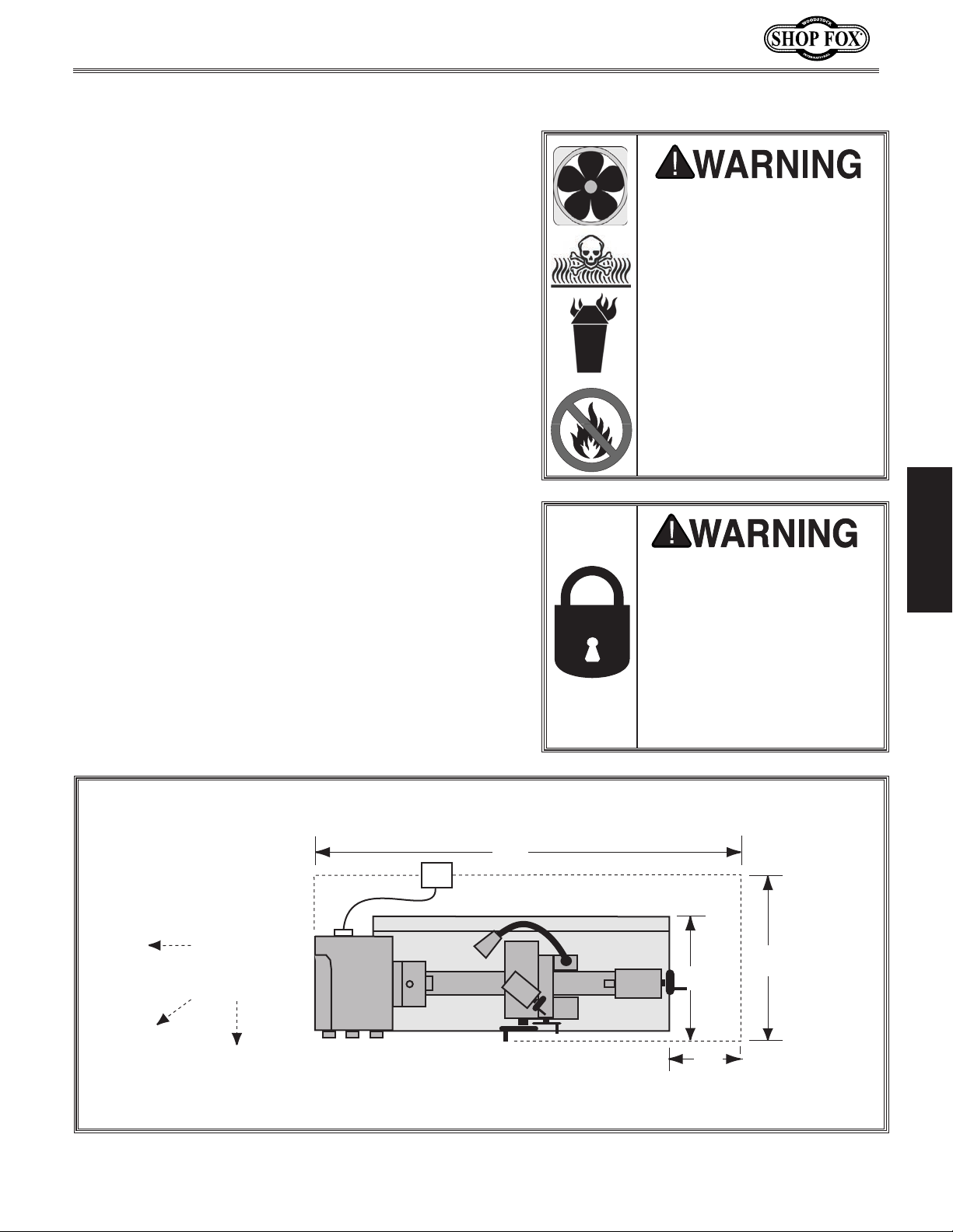
Machine Placement
• Floor Load: Your lathe is a heavy load distributed
in a small footprint, so you must reinforce the floor
if required. The floor MUST be level, or the lathe
frame and ways may twist and distort over time.
• Working Clearances: Consider existing and anticipated needs, service panel access, length of rods
to be loaded into the lathe, and space for auxiliary stands, work tables or other machinery when
establishing a location for your lathe (see Figure 11
for dimensions).
• Lighting: Lighting should be bright enough to eliminate shadow and prevent eye strain.
• Electrical: Outlets must be located near each
machine, so power cords are clear of high-traffic
areas.
ALWAYS work in wellventilated areas far from
possible ignition sources
when using solvents to clean
machinery. Many solvents
are toxic when inhaled or
ingested. Use care when
disposing of waste rags
and towels to be sure
they DO NOT create fire
or environmental hazards.
NEVER use gasoline or
petroleum-based solvents
to clean your lathe.
SETUP
MAKE your shop “child safe.”
Ensure that your workplace
is inaccessible to youngsters
by closing and locking all
entrances when you are
away. NEVER allow untrained
visitors in your shop when
assembling, adjusting or
operating equipment.
Keep
Workpiece
Loading Area
Unobstructed
80"
220V
Supply
Lathe
Figure 11. Minimum wall clearances.
-15-
Chip Tray
60"
36"
24"
Page 18
M1112 12" x 36" Gunsmithing Lathe (Mfg. Since 4/08)
2 T1
6 T3
22NC
4 T2
1 L1
5 L3
21NC
GSC1-1801
KM1
3 L2
A1
A2
26
30313233E
2524232221
20
13NO
JZC3 40d
33NO
43NO
23NO
14NO
34NO
44NO
24NO
2 T1
6 T3
22NC
4 T2
1 L1
5 L3
21NC
GSC1-1801
KM2
KA0
3 L2
Ground
NO
NC
1L1
3L2
5L3
2T1
6T3
4T2
STOP
RESET
95
98
97
JRS4-09/25d
FR1
11
13
A
6
96
TC
20-21 = 110V
20-22 = 220V
20-23 = 230V
20-24 = 240V
20-25 = 380V
20-26 = 400V
A1A1A2
A2
L
L
L
N
N
N
U1
N
N
N
L
L
L
LL0
0
11PE
PE
0
0
0
1
1
2
2
233
55667
7
U2
U2U2Z1
Z1Z1Z2Z2Z2
1066
10
1101326754
PE
PE
Z2Z1U2
U1
PE
L N
8
5
Transformer
Relay
Contactor
Contactor
Contactor
2A
110V
110V
2A
5A
110V
110V
5A
To
Work Light
To
Power Source
To
Motor
To
Control Panel
To
Spindle Switch
8
L
L
11
11
11
11
Mounting to Shop Floor
Although not required, we recommend that you mount
your new machine to the floor. Because this is an optional
step and floor materials may vary, floor mounting
hardware is not included. Generally, you can either bolt
your machine to the floor or mount it on machine mounts.
Both options are described below. Whichever option you
choose it will be necessary to use a precision level to
level your machine.
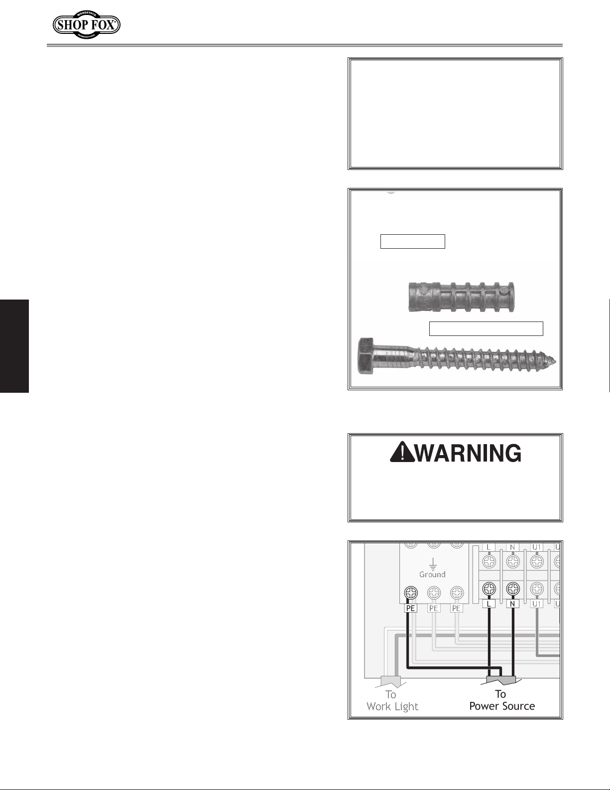
Bolting to Concrete Floors
Anchor studs, lag screw and anchor (Figure 12) are two
popular methods for anchoring an object to a concrete
flo or. We suggest you research the many options and
methods for mounting your machine and choose the one
that best fits your specific application.
Power Connection
Before the machine can be connected to the power
SETUP
source, an electrical circuit, power cord, plug, and
receptacle must be prepared per the ELECTRICAL section
in this manual, and all previous setup instructions in the
manual must be complete to ensure that the machine has
been assembled and installed properly.
NOTICE
Anchor studs are stronger and more
permanent alternatives to lag shield
anchors; however, they will stick out of
the floor, which may cause a tripping
hazard if you decide to move your
machine at a later point.
Anchor Stud
Lag Screw and Anchor
Figure 12. Typical fasteners for mounting
to concrete floors.
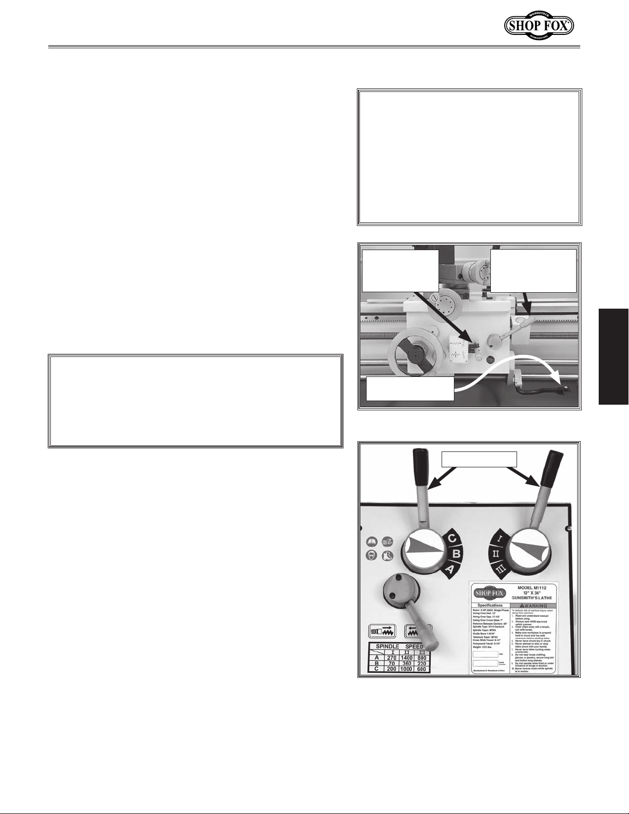
To connect the power cord, do these steps:
1. Make sure the power cord is NOT connected to
power.
2. Open the electrical cabinet and identify the L and
N terminals, and the grounding plate (PE) at the
bottom left of the cabinet (see Figure 13).
3. Attach insulated crimp-on wire terminals to the
wires of the power cord.
4. Securely connect the incoming ground to the PE
terminal and the two incoming hot leads to the L
and N terminals.
5. Close and secure the electrical cabinet.
Before connecting the machine to
power, always make sure the reset
button on the control panel is pushed
in to avoid unexpected start-ups.
Figure 13. Locations of power cord
connections inside the electrical cabinet.
-16-
Page 19
M1112 12" x 36" Gunsmithing Lathe (Mfg. Since 4/08)
Test Run & Break-In
The purpose of the test run and break-in is to make sure
the lathe and safety features operate correctly, and
that the lathe can enter service quickly without bearing
damage if heavy work loads are immediately anticipated.
To begin the test run & break-in procedure, do these
steps:
1. Make sure the lathe is lubricated and the headstock
oil level is full. Refer to Lubrication on Page 40.
2. Make sure the chuck is correctly secured to the
spindle. Refer to Mounting Chuck and Faceplate on
Page 22 for details.
3. Disengage the half-nut lever and the feed lever
(Figure 14).
NOTICE
NEVER shift lathe gears when lathe
is operating, and make sure both the
half-nut lever and the feed lever are
disengaged before you start the lathe!
Otherwise the lathe will feed the apron
into the chuck or tailstock causing
severe lathe damage.
Feed Lever is
Horizontal
(Disengaged)
Half-nut Lever
is Pulled Up
(Disengaged)
4. Connect power to the machine.
NOTICE
Make sure all power feed levers and dials are
disengaged before starting the lathe! Thoroughly
familiarize yourself with all the controls and their
functions before using any power feed!
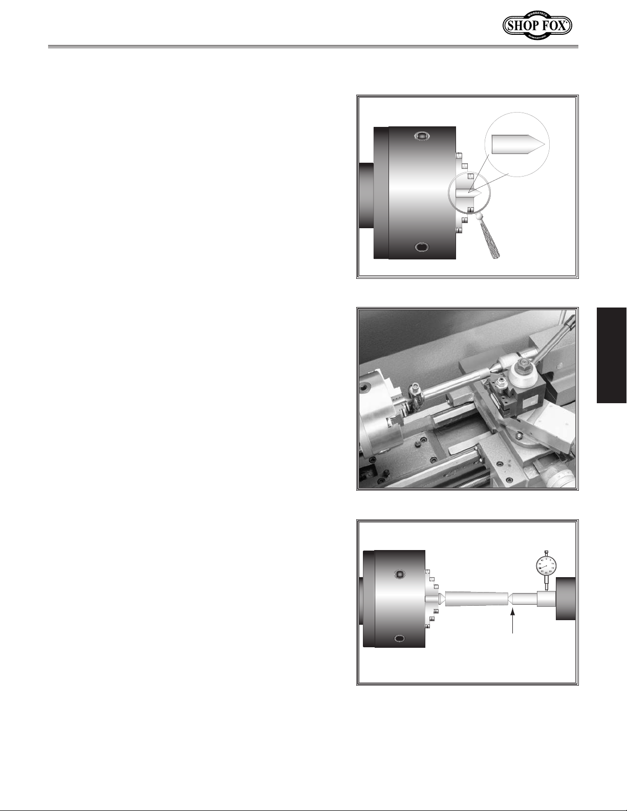
5. Rotate the red stop/RESET button (Figure 15)
clockwise so it pops out.
6. Make sure the spindle rotation ON/OFF lever is in
the central or neutral position (Figure 14).
7. Move the speed levers to B and
rotate at 70 RPM (Figure 15).
I so the spindle will
SETUP
Spindle Rotation
ON/OFF Lever
Figure 14. Apron controls.
Speed Levers
-17-
Figure 15. Headstock controls.
Page 20

M1112 12" x 36" Gunsmithing Lathe (Mfg. Since 4/08)
8. Push the POWER START button, then move
the spindle rotation ON/OFF lever (Figure 14)
down until the chuck turns. The top of the
chuck should turn toward you.
— If you hear squealing or grinding noises,
turn the lathe OFF immediately and correct
any problem before further operation.
— If the problem is not readily apparent, refer
to Troubleshooting on Page 43.
9. Push the emergency stop button.
— If the lathe does not stop, turn the lathe
OFF with the spindle rotation ON/OFF
lever, and disconnect the lathe from power.
Refer to Troubleshooting on Page 43 for
correction.
10. Return the spindle rotation ON/OFF lever
to STOP, reset the emergency stop button,
restart the lathe, and let the lathe run for a
minimum of 10 minutes in both directions.
11. Turn the lathe OFF, and move the speed
levers to C and
200 RPM. Run the lathe in both directions for
10 minutes.
12. Repeat Step 9 for the remaining RPM ranges,
progressively increasing in RPM. When these
steps are complete, the lathe is broken in.
13. Drain and refill the lubricant in the
headstock with Mobil DTE Light or ISO 32 an
equivalent. Refer to Lubrication on Page 40
for steps and apron oil change interval.
I so the spindle will rotate at
SETUP
-18-
Page 21
M1112 12" x 36" Gunsmithing Lathe (Mfg. Since 4/08)
Looking down from above.
Move tailstock toward
back of lathe
1
/2 the
amount of taper.
Tailstock
The tailstock alignment was set at the factory with the
headstock. However, we recommend that you take the
time to ensure that the tailstock is aligned to your own
desired tolerances.
To align the tailstock, do these steps:
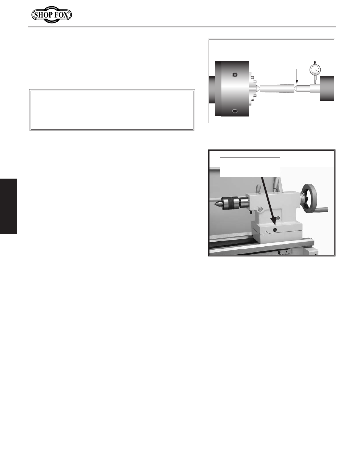
1. Center drill a 6'' long piece of bar stock on both
ends. Set it aside for use in Step 4.
2. Make a dead center by turning a shoulder to make
a shank. Flip the piece over in the chuck and turn a
60° point (see Figure 16). As long as it remains in
the chuck, the point of your center will be accurate
to the spindle axis.
Note: Keep in mind that the point will have to be
refinished whenever it is removed and returned to
the chuck.
Figure 16. Finished dead center.
SETUP
3. Place the live center in your tailstock.
4. Attach a lathe dog to the bar stock from Step 1 and
mount it between the centers (as shown in Figure
17).
5. Turn approximately 0.010" off the diameter.
6. Mount a dial indicator so that the plunger is on the
tailstock barrel (Figure 18).
7. Measure the stock with a micrometer. If the stock is
wider at the tailstock end, the tailstock needs to be
moved toward the cutter the amount of the taper
(Figure 18).
— If the stock is thinner at the tailstock end, the
tailstock needs to be moved away from the
operator by half the amount of the taper (Figure
19).
Figure 17. Bar stock mounted on centers.
Figure 18. Adjusting for headstock end
taper.
-19-
Page 22
M1112 12" x 36" Gunsmithing Lathe (Mfg. Since 4/08)
Move tailstock toward
front of lathe
1
/2 the
amount of taper.
Looking down from above.
8. Loosen the tailstock lock lever and adjust the
tailstock offset by half the taper by turning the
adjustment set screw (Figure 20). Turn another
0.010'' off of the stock and check for taper. Repeat
as necessary until the desired amount of accuracy is
achieved.
NOTICE
DO NOT forget to lock the tailstock to the ways
after each adjustment.
Figure 19. Adjusting for tailstock end
taper.
Adjustment Screw
On Both Sides
SETUP
Figure 20. Tailstock left adjustment
location.
-20-
Page 23
M1112 12" x 36" Gunsmithing Lathe (Mfg. Since 4/08)
I II III
SPINDLE SPEED
OPERATIONS
General
NOTICE
Complete the Test Run and Break-In procedure on
Page 17 before using this lathe for any cutting or
threading operations; otherwise, gear box damage
may o cc ur.
The Model M1112 will perform many types of operations
that are beyond the scope of this manual. Many of these
operations can be dangerous or deadly if performed
incorrectly.
The instructions in this section are written with the
understanding that the operator has the necessary
knowledge and skills to operate this machine. If at any
time you are experiencing difficulties performing any
operation, stop using the machine!
If you are an inexperienced operator, we strongly
recommend that you read books, trade articles, or seek
training from an experienced lathe operator before
performing any unfamiliar operations. Above all, your
safety should come first!
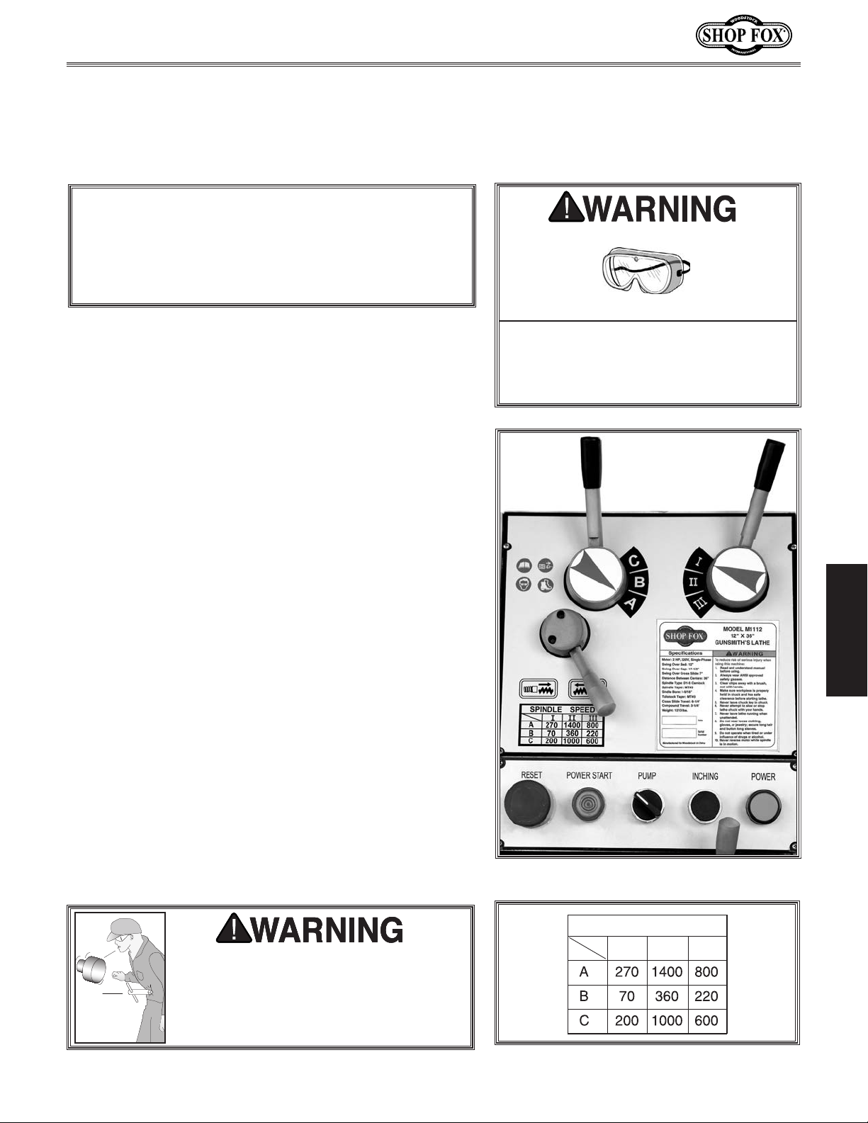
Spindle Speeds
The spindle speed or RPM is controlled by the speed
control levers (Figure 21). Use the chart in Figure 22 to
find the best spindle speed required for your task.
Always wear safety goggles when operating this lathe. Failure to comply may
result in a serious eye injury resulting
in blindness.
OPERATIONS
The chart to the right shows the various combinations of
knob positions for achieving a desired speed.
Example:
To select a spindle speed of 270 RPM, move the alpha
lever until the indicator arrow points to A. Move the
numeric lever so it points to
I (Figure 21).
Securely clamp your workpiece and
remove the chuck key! Thrown objects
from a lathe can cause serious injury or
death to the operator and to bystanders
many feet away.
-21-
Figure 21. Spindle control levers.
Figure 22. Speed chart.
Page 24
M1112 12" x 36" Gunsmithing Lathe (Mfg. Since 4/08)
Mounting Chuck or
Faceplate
The Model M1112 is shipped with the 3-jaw chuck
installed. This is a scroll-type chuck, meaning that all
three jaws move in unison when adjusted.
The 4-jaw chuck, on the other hand, features
independent jaws. This chuck is used for square or
unevenly-shaped stock.
If either chuck cannot hold your workpiece, the castiron faceplate has slots for T-bolts that hold standard or
custom clamping hardware. With the correct clamping
hardware, this faceplate will hold non-cylindrical parts
such as castings.
The chucks and faceplate have a D-5 Camlock mount.
Please note that there are lines stamped into the cam
and on the chuck body ( Figure 24). A chuck key is used
to turn the locking cams.
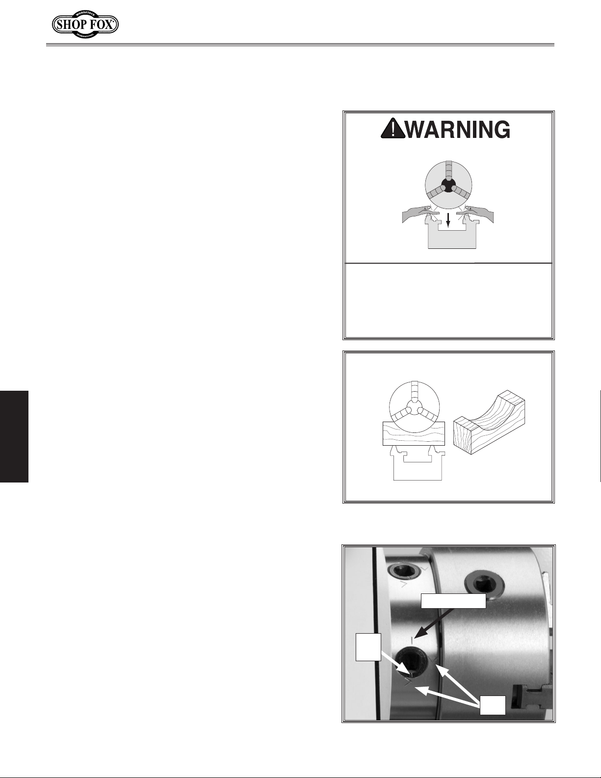
PINCH HAZARD! Protect your hands
and precision ground bedways
with plywood when removing lathe
chuck! The heavy weight of a falling chuck can cause serious injury.
To remove the existing chuck, do these steps:
1. DISCONNECT LATHE FROM POWER!
2. Place a piece of plywood across the lathe ways and
position it just under the chuck. The board should be
at least 8" wide and 10" long.
3. Turn a cam with the chuck key until the cam line
OPERATIONS
aligns with the spindle line mark shown in Figure 24.
4. Turn the other cams in the same way. Make sure to
support the chuck with one hand as you align the last
cam. The chuck may come off at this point, so be
ready to support its weight.
5. Remove the chuck key.
— If the chuck is still tight on the spindle, tap the
back of the chuck with a rubber or wood mallet
while supporting the bottom of the chuck with a
chuck cradle.
— If the chuck does not immediately come off, rotate
the spindle approximately 60˚ and tap again. Make
sure all the marks on the cams and spindle are in
proper alignment.
Figure 23. Simple chuck cradle made of
scrap lumber.
Spindle Line
Cam
Line
V's
-22-
Figure 24. Cam lines aligned to spindle
line.
Page 25
M1112 12" x 36" Gunsmithing Lathe (Mfg. Since 4/08)
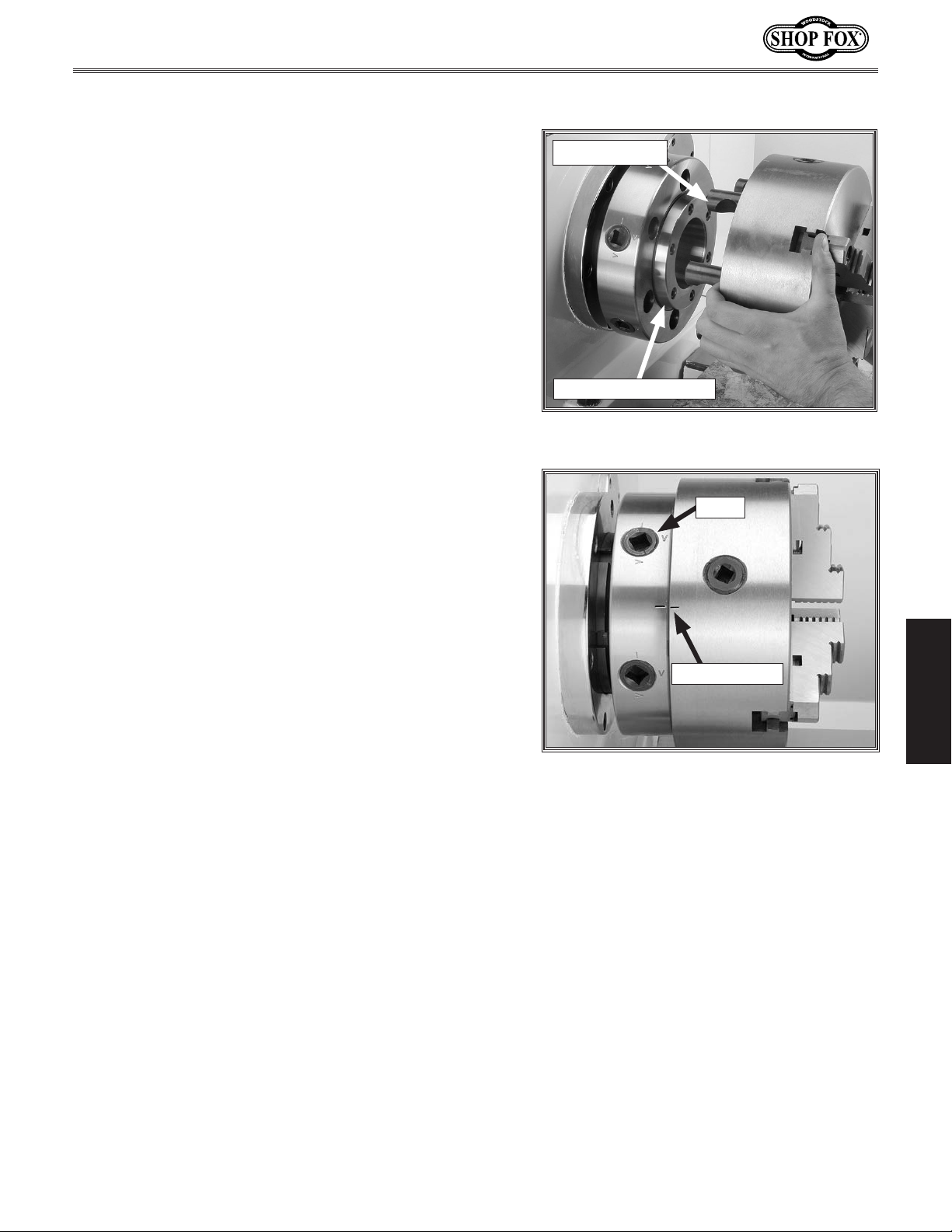
To install a chuck, do these steps:
1. DISCONNECT LATHE FROM POWER!
2. Place a piece of plywood across the lathe bed, wipe
clean the spindle nose taper (Figure 25) and the
mating surface on the chuck with a rag.
3. If stamped with chuck and spindle timing marks
(Figure 26), align the marks and the camlock studs
in the back of the chuck with the holes on the
spindle face, and slide the chuck onto the spindle.
4. While supporting the weight of the chuck, turn
one cam with the chuck key until the cam line is
between the two V's on the spindle. Do not tighten
at this time.
5. Rotate the spindle and repeat Step 4 on the opposite
cam.
Camlock Stud
Spindle Nose Taper
Figure 25. Installing and removing the
chuck.
6. Rotate the spindle and repeat Step 4 on the rest of
the cams in an alternating manner.
7. When all cams are snug, return to the first cam and
tighten the cam completely. Repeat this step with
the rest of the cams.
Cam
OPERATIONS
Timing Marks
Figure 26. Tightening the camlocks when
the chuck is in time with the spindle.
-23-
Page 26
M1112 12" x 36" Gunsmithing Lathe (Mfg. Since 4/08)
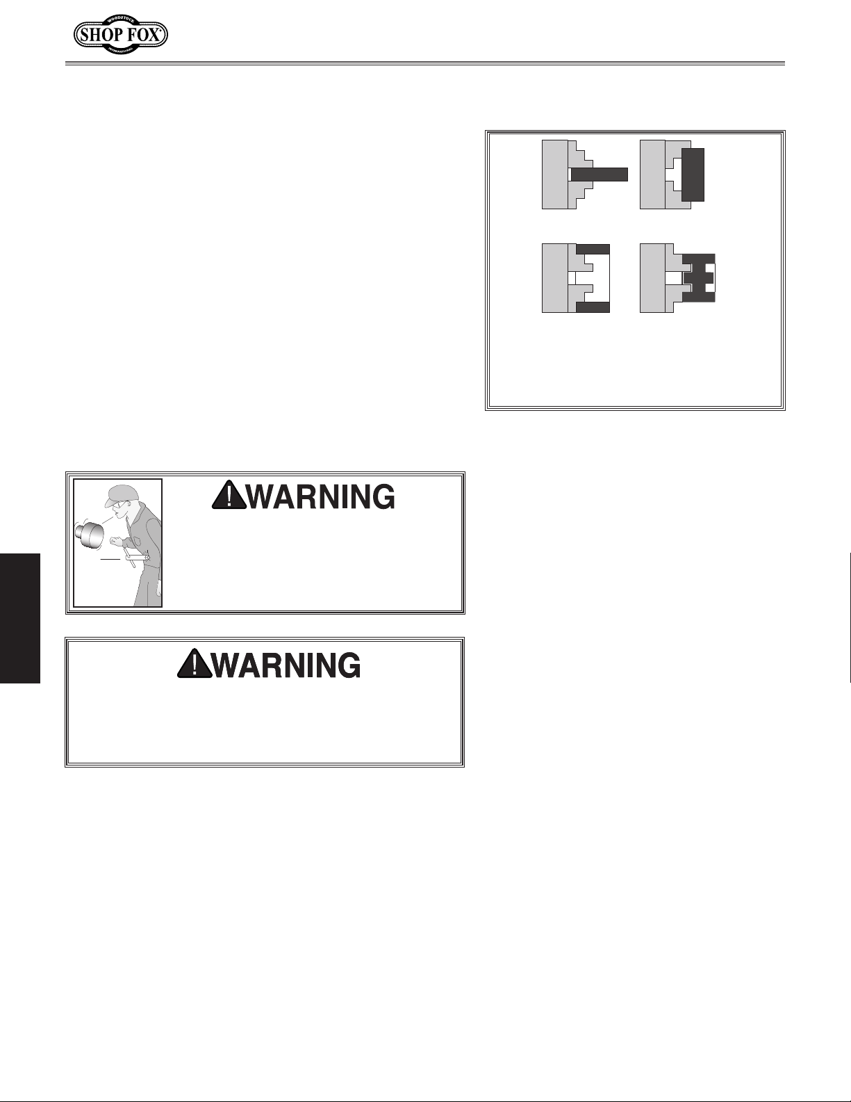
To load a workpiece, do these steps:
1. With the chuck key, open the jaws so the workpiece
lays flat against the chuck face and jaw step or
fits in the through hole. For jaw and work holding
options, see Figure 27.
2. Slowly turn the workpiece, and turn the chuck
wrench until the jaws make contact with the
workpiece.
3. Turn the chuck by hand to make sure you have even
contact with all three jaws and the workpiece is not
off center.
• If the workpiece is off center, loosen the jaws and
adjust the workpiece.
• If the workpiece is seated correctly, tighten the
jaws.
Securely clamp your workpiece and
remove the chuck key! Thrown objects
from a lathe can cause serious injury or
death to the operator and to bystanders
many feet away.
Clamping on an Outside Diameter
Clamping in an Inside Diameter
Figure 27. Loading a workpiece.
OPERATIONS
If the workpiece protrudes more than 2.5 times its
own diameter, support it with a center, and possibly
a steady rest. Otherwise the workpiece can deflect or
come out of the chuck, causing injury.
-24-
Page 27

M1112 12" x 36" Gunsmithing Lathe (Mfg. Since 4/08)
Swapping Jaws
The three-jaw scroll chuck has removable hardened steel
jaws (Figure 28). The outside of the jaws are used to hold
the workpiece from the outer diameter.
Numbered from 1–3, the jaws must be used in the
matching numbered jaw guides, see (Figure 29).
Note: The chuck need not be removed from the spindle to
swap the jaws.
To swap a set of jaws, do these steps:
1. DISCONNECT LATHE FROM POWER!
2. Place a piece of wood over the ways to protect them
from potential damage.
3. Turn the chuck key counterclockwise and back the
jaws out.
4. Clean the jaw mating surfaces and apply a film of
white lithium grease to the mating surfaces.
5. Set the old jaws aside in a safe place free of
moisture and abrasives.
6. Rotate the chuck key clockwise until you see the tip
of the scroll-gear lead thread just begin to enter jaw
guide #1 (see Figure 30).
7. Insert jaw #1 into jaw guide #1 and hold the jaw
against the scroll gear.
8. Rotate the chuck key clockwise one turn to engage
the tip of the scroll-gear lead thread into the jaw.
Pull on the jaw now and it should be locked into the
jaw guide.
Figure 28. Chuck and jaw selection.
Jaw Guide #1
Figure 29. Jaw guide number.
Jaw Numbers
OPERATIONS
9. Repeat the steps on the remaining jaws.
• If installed correctly, all three jaws will converge
together at the center of the chuck.
• If the jaws do not come together, repeat this pro-
cedure until they do.
-25-
Lead Thread
Figure 30. Lead thread on scroll gear.
Page 28

M1112 12" x 36" Gunsmithing Lathe (Mfg. Since 4/08)
Four-Jaw Chuck
Four-jaw chucks feature hardened steel jaws that are
adjusted independently. Each jaw can be removed
from the chuck body and reversed. Independent jaw
adjustment and re versal allows for a wide range of work
holding versatility.
To install the four-jaw chuck, refer to the Mounting
Chuck or Faceplate procedures on Page 22.
To load a workpiece in the four-jaw chuck, do these
steps:
1. Using the chuck key, open each jaw so the workpiece
will lay flat against the chuck face.
2. Support the workpiece.
3. Position and lock the tailstock, then turn the
tailstock quill so the dead center makes contact or
is close to the center point of your workpiece (see
Figure 32).
4. Turn each jaw until it just makes contact with the
workpiece.
5. In an opposing pattern, tighten each jaw in small
increments. After you have adjusted the first jaw,
continue tightening the opposing jaw. Check the
dead center alignment frequently to make sure
OPERATIONS
you have not wandered off your index point due to
applying too much pressure to a single jaw.
6. After the workpiece is held in place, back the
tailstock away and rotate the chuck by hand. The
center point will move up and down when the chuck
is rotated if the workpiece is out of center.
PINCH HAZARD! Protect your hands
and precision ground bedways
with plywood when removing lathe
chuck! The heavy weight of a falling chuck can cause serious injury.
Figure 31. Simple chuck cradle made of
scrap lumber.
Securely clamp your workpiece and
remove the chuck key! Thrown objects
from a lathe can cause serious injury or
death to the operator and to bystanders
many feet away.
-26-
Figure 32. Clamping workpiece.
Page 29

M1112 12" x 36" Gunsmithing Lathe (Mfg. Since 4/08)
7. Make fine adjustments by slightly loosening one jaw
and tightening the opposing jaw until the workpiece
is precisely aligned.
8. Use a dial indicator to fine-tune your adjustments
(see Figure 33), and use a lower RPM when
machining heavy eccentric workpieces.
PROJECTILE HAZARD! Use a lower RPM when machining
heavy eccentric workpieces. Otherwise, the workpiece
can be ejected by the chuck and cause serious injury.
Faceplate
The faceplate can be used to turn non-cylindrical parts or
for off-center turning by clamping the workpiece to the
faceplate.
Figure 33. Centering workpiece.
To install the faceplate, refer to the Mounting Chuck or
Faceplate procedures on Page 22 to mount the faceplate.
To load a workpiece, do these steps:
1. Support the workpiece on the faceplate with a
minimum of three independent clamping devices
(see Figure 34). Failure to follow this step may lead
to deadly injury to yourself or bystanders. Take into
account rotation and the cutting forces applied to
the workpiece when clamping to the faceplate. Make
sure your clamping application will not fail!
Note: Depending on the workpiece, some additional
support or counter-balance may be needed.
2. Slide the tailstock to the workpiece.
3. Lock the tailstock and then turn the tailstock quill so
the dead center makes contact with the center point
of your workpiece.
4. Lock the tailstock quill when sufficient pressure is
applied to hold the workpiece in place.
OPERATIONS
Figure 34. Faceplate with properly
clamped workpiece in four locations.
Use a minimum of three independent
clamping devices when turning eccentric
workpieces. Failure to provide adequate
clamping will cause workpiece to eject,
which may cause serious injury or death.
Note: Use a lower RPM when machining heavy
eccentric workpieces.
5. Clamp the workpiece securely and counter-balance
as needed.
-27-
Page 30

M1112 12" x 36" Gunsmithing Lathe (Mfg. Since 4/08)
Centers
A tailstock center supports stock that is too long to be
supported by the chuck alone. The tailstock barrel and
live center have an MT#3 taper. Included with this lathe
is an MT#3 to MT#5 spindle sleeve. If you need to install
a center in the spindle when using the faceplate, you can
do so by using this adapter sleeve.
Before installing any center or arbor, make sure that the
mating surfaces are perfectly clean. These parts will last
longer and remain accurate if properly maintained. If oil
is present on the mating surfaces, the tapers will not
interlock.
To install the center, insert the end of the center into
the tailstock bore until it seats. Once the workpiece is
installed, the force of a mounted workpiece will fully seat
the t ape r.
When using a live center, the tailstock barrel should
protrude about
To remove the live center, back the tailstock barrel all
the way into the tailstock casting. The live center will
pop out. Be sure to catch it when it comes out to avoid
damaging the tip.
1
⁄2" and not more than 3" (see Figure 35).
Spindle Spider
OPERATIONS
Remove the spider screws when not in use. Always
disconnect the lathe from power when installing,
removing, or adjusting the spider screws. Ignoring
this warning can lead to personal injury or machine
damage.
Figure 35. Live center installed in
tailstock.
Your lathe is equipped with a set of spindle support bolts
known as the "spider" (Figure 36). Use the spider when
a long workpiece has the potential to wobble or vibrate
when it extends through the outboard side of the lathe.
The tips of the spider screws have brass wear pads that
hold the workpiece without causing indents in the finish.
When installed, make sure to always use the jam nuts to
lock each spider screw in position. Merely tightening the
spider screws against the workpiece and leaving the jam
nuts loose is not safe. The spiders screws may loosen up
during lathe operation and crash into the lathe end cover.
-28-
Figure 36. Spider.
Page 31

M1112 12" x 36" Gunsmithing Lathe (Mfg. Since 4/08)
Steady Rest
The steady rest supports long, small diameter stock that
otherwise could not be turned because of deflection. The
steady rest fingers are fitted with bearings that maintain
consistent non-wearing support throughout the cut. The
steady rest can also be used in place of the tailstock to
allow for cutting tool access at the end of your workpiece.
To use the steady rest, do these steps:
1. Secure the steady rest to the bedway from below
with the locking plate, then snug the mounting bolt
(Figure 37).
2. Adjust the fingers until the bearings make contact
and support the workpiece. Do not over-tighten
the fingers or they will cause deflection in the
workpiece.
Mounting Bolt
Figure 37. Steady rest in place.
3. Oil the finger bearings and the rolling surfaces while
in use to assist in friction-free support.
Follow Rest
The follow rest is normally used with small diameter
stock to prevent the workpiece from “springing” under
pressure from the turning tool. The follow rest fingers are
fitted with bearings that maintain consistent non-wearing
support throughout the cut.
To use the follow rest, do these steps:
1. Secure the follow rest to the saddle with the two
cap screws (Figure 38).
2. Adjust the fingers until the bearings make contact
and support the workpiece. Do not over-tighten the
fingers as to cause deflection in the workpiece.
3. Lubricate the finger bearings and the rolling surfaces
while in use to assist in low friction support.
OPERATIONS
Mounting Cap Screws
Figure 38. Follow rest secured to saddle.
-29-
Page 32

M1112 12" x 36" Gunsmithing Lathe (Mfg. Since 4/08)
Feed Direction Lever
NOTICE
NEVER attempt to shift a lever while the lathe is
running! And when shifting a lever, NEVER force it. If
the lever will not engage, rotate the chuck by hand
while keeping light pressure on the lever. As the
chuck rotates it aligns the gears and the lever will
engage.
Your lathe can cut left or right while feeding or threading,
and it can cut across both ways for facing operations. This
feed direction is controlled by the feed direction lever
shown in Figure 39.
When the selection lever is positioned as depicted in
Figure 39, the carriage will move to the right along
the bed or the cross feed will travel away from the
operator. The cross feed and longitudinal feed selection is
controlled on the apron.
Figure 39. Feed direction lever.
To reverse the direction of the feeding or threading
operation, stop the lathe, move the feed direction lever
completely to the right or left.
When the lever is positioned in the middle, no gear ratio
is selected, and the gear train feeding the apron is in
neutral.
OPERATIONS
Feed Rod Lever
The feed rod can be selected by moving the lever to
the left as in Figure 40. Use this position for all feed
operations.
When the lever is positioned straight up, no drive
mechanism is selected and the gear train feeding the
apron is in neutral.
When the lever is moved to the right, no gear ratio
is selected, and the gear train feeding the apron is in
neutral.
-30-
Figure 40. Feed rod lever.
Page 33

M1112 12" x 36" Gunsmithing Lathe (Mfg. Since 4/08)
Gearbox Levers
NOTICE
NEVER attempt to shift a lever while the lathe is
running! And when shifting a lever, NEVER force it. If
the lever will not engage, rotate the chuck by hand
while keeping light pressure on the lever. As the
chuck rotates it aligns the gears and the lever will
engage.
The two levers (Figure 41) at the bottom of the headstock
change the feed rate or the number of threads cut perinch. The left-hand lever engages in alpha positions A, B,
C, D, and E; and the right-hand lever engages in numeric
positions 1, 2, 3, 4, 5, 6, 7, and 8.
Use the feed rate chart shown in Figure 42 to position
the quick change gearbox levers.
Figure 41. Quick change gearbox.
Feed Rate Chart
The far left column in the feed rate chart (Figure 42)
shows which change gears must be installed so the chart
will be applicable.
For example: Using the metric chart to make a 0.158mm
per revolution longitudinal cut, refer to the row that has
this symbol: .
Then put the left-hand lever in the C position, and the
right-hand lever in the 4 position.
To perform a facing cut, use the chart the same way
but refer to the row that has this symbol: .
Note: When either of the two selector levers are left in
the down position, the drive train is disengaged and is in
neutral.
OPERATIONS
Figure 42. Feed rate chart.
-31-
This symbol indicates longitudinal feed.
This symbol indicates cross feed rates.
Page 34

M1112 12" x 36" Gunsmithing Lathe (Mfg. Since 4/08)
Carriage/Cross Feed
Lever
Longitudinal and cross slide powered motions are
controlled by the carriage/cross feed lever. The lever
pivots through two stops that require moving the lever
left and right as well as up and down. Moving this lever
upward activates the automatic longitudinal feed. Moving
the lever downward activates the cross slide (Figure 43).
Half-Nut Lever and Inch
Threading
The half-nut lever clamps and releases the half-nut, which
clamps around the leadscrew (Figure 44). The lever is
only engaged while cutting threads.
Note: If the apron feed lever is engaged, the half-nut
lever is blocked from use; and if the half-nut lever is
engaged the apron lever is blocked from use. If both
levers are engaged at the same time apron damage will
o c cu r.
After the carriage has been returned, the thread dial tells
you when to re-engage the half-nut and resume threading
(Figure 44).
Figure 43. Carriage/cross feed lever in
neutral position.
Half-nut
Lever
Dial
When the cap screw is loosened, the thread dial housing
pivots so its gear can be engaged or disengaged from the
OPERATIONS
lead screw. When engaged, the dial will turn when the
lead screw and spindle are turning.
When the half-nut lever is engaged, the dial stops turning.
By carefully engaging the half-nut as the appropriate line
or number passes by the indicator mark, a thread can be
re-entered for its next pass of the cutter without wiping
out the previous cut.
The thread dial chart shown in Figure 45 indicates when
to use the thread dial if inch threads are to be cut. If an
inch thread is divisible by 8, then you don't need not use
the thread dial. If cutting metric threads, you cannot use
the thread dial.
Cap Screw
Figure 44. Threading dial and half-nut
lever.
Figure 45. Thread dial chart.
-32-
Page 35

M1112 12" x 36" Gunsmithing Lathe (Mfg. Since 4/08)
While other thread pitches may be achieved, the Model
M1112 is designed so that gear changes are not needed for
cutting inch threads. However, you will have to move the
feed direction lever to the direction of thread you want
to cut, and then move the feed rod lever to the right. To
get the needed threads in inches, you will then use the
standard thread chart (Figure 46) to determine which
positions to move the quick change levers.
Example:
If the desired threads are 11 threads per inch (Figure 46),
move the quick change gearbox levers to positions B and
5. As the thread dial chart shows, engage the half-nut
when the thread dial reads 1 or 3 and begin your first
cut.
When the cut is complete, disengage the half-nut and
manually return the carriage to the beginning of the cut.
Watch the dial. When the 1 or the 3 on the dial comes
around to the indicator mark, engage the half-nut. Begin
your second pass. Repeat this process until the desired
depth of cut is achieved.
Change Gears & Metric
Threading
This lathe can cut 29 different metric threads, but gear
changes are required to cut all of the listed metric
threads. These gear changes take place on the left hand
end of the machine (Figure 47).
Figure 46. Standard thread chart.
F
86-Teeth
91-Teeth
Figure 47. Change gear locations.
G
OPERATIONS
The chart is divided into 3 main columns, starting from
the left: Gear diagram, Combination of Gears and
Pitch.
To use the chart, do these steps:
1.
Find the desired pitch in the chart
m
2. Below the
corresponding number above the desired pitch and
change the right hand quick change lever to that
position.
Note: The holes on the quick change gearbox are
letterd and numbered from left to right.
3. To the left of the desired pitch is a small column
with a letter. This letter indicates placement of the
left hand quick change lever. Move the lever to the
corresponding location.
/m Per Pitch label are numbers. Find the
(Figure 48)
m
/m Per
.
-33-
Figure 48. Metric thread chart.
Page 36

M1112 12" x 36" Gunsmithing Lathe (Mfg. Since 4/08)
5mm
Hex
Socket
17mm
Arm-Support
Hex Nut
3mm
Hex
Socket
17mm
Gear-Support
Hex Nut
4. In the “Combination of Gears” column
(Figure 49)
are 3 small columns. The numbers below F and G
represent the number of gear teeth on a change
gear. Find the required change gears that have the
corresponding number of teeth as stated in the chart
to the left of the desired pitch.
5. Open the gear and belt cover.
6. Loosen the 17mm arm-support hex nut and rotate
the bracket so the middle gear moves away from
gear F (Figure 49).
7. Loosen the 17mm gear-support hex nut and slide the
middle gear away from gear G.
8. Use a 3mm hex wrench and remove the cap screw
and remove change gear F.
9. Use a 5mm hex wrench to loosen the set screw in
the hub of gear G, and pull the gear off of the shaft.
10. Replace change gears F and G with the gears that
will produce your desired metric thread pitch and
tighten the fasteners to hold the gears on the shafts.
OPERATIONS
11. Slide the appropriate middle gear against gear G
until they mesh with (0.002" to 0.004" backlash) and
tighten the cap screw.
12. Rotate the appropriate middle gear against gear F
until they mesh with (0.002" to 0.004" backlash) and
tighten the cap screw.
Example:
If the desired metric pitch is 1.25mm, move the quick
change levers to positions 1 and C. The "Combination
of Gears" column shows that the F position change gear
needs 50 teeth and the G position change gear needs 60
teeth (Figure 49). A diagram on the left side of the chart
shows that the 50 tooth change gear meshes with the 91
tooth middle gear and the 60 tooth change gear meshes
with the 86 tooth middle gear.
Remember, you cannot use the thread dial for the metric
threads. You must keep the half-nut lever engaged
throughout the whole threading process until the threads
are complete.
Figure 49. Metric thread chart and change
gear placement.
-34-
Page 37

M1112 12" x 36" Gunsmithing Lathe (Mfg. Since 4/08)
Carriage Handwheels
Carriage Handwheel
The carriage handwheel (Figure 50) moves the carriage
left or right along the bed. This manual control is
necessary when setting up the machine for turning
or when manual movement is desired during turning
operations.
Cross Slide Handwheel
The cross slide handwheel moves the cross slide toward
and away from the work. Turning the dial clockwise moves
the slide toward the workpiece. The graduated dial can
be adjusted by holding the handwheel with one hand and
turning the dial with the other.
Compound Slide Handwheel
The compound slide handwheel (Figure 50) controls the
position of the cutting tool relative to the workpiece.
This slide is adjustable to any angle. The graduated dial is
adjustable using the same method as the dial on the cross
slide. Angle adjustment is locked by hex nuts on the base
of the top slide.
Compound
Slide
Handwheel
Carriage Handwheel
Figure 50. Handwheel locations.
Cross Slide
Handwheel
Tool Post & Holder
Figure 51 shows the quick change tool post and holder.
Cutting tools can be secured and removed by tightening or
loosening the clamping screws in the top of the holder. A
threaded stud is mounted in the top of the holder and has
a knurled thumb wheel. Rotating the thumb wheel allows
for adjustment of the tool holder so the cutting tool can
be centered. The handle on the tool post can be rotated
to lock and unlock the tool holder onto the dovetail ways.
The tool post may be rotated by loosening the nut at the
top of the tool post.
OPERATIONS
Figure 51. Quick change tool post and
holder.
-35-
Page 38

M1112 12" x 36" Gunsmithing Lathe (Mfg. Since 4/08)
Tailstock
The tailstock (Figure 52) serves many functions. The
primary use is for holding centers and drill chucks. The
barrel has a Morse taper
graduations in millimeters and inches.
Tailstock Handwheel
Turning the handwheel advances or retracts the barrel
in the tailstock. The graduated dial on the handwheel is
adjustable.
Barrel Lock Lever
This lever locks the tailstock barrel in place.
Side Lock Lever & Torque Tightening
This removable lever locks the tailstock in place on the
lathe bed. The socket that it fits into will accept a
drive torque wrench.
#
3 bore and is imprinted with
1
⁄2"
Tailstock
Handwheel
Barrel Lock
Side Lock Lever
Figure 52. Tailstock controls.
Lever
For repeating very accurate vertical alignment positioning
time after time, remove the side lock lever (Figure 52),
and use an inch-pound torque wrench fitted with a
1
⁄2" drive adapter to lock the tailstock into position.
to
You can use a foot-pound torque wrench but DO NOT
exceed 40 lbs/ft of torque or you may damage the ways
and the tailstock. When tightening the tailstock down to
the maximum torque of 40 lbs/ft, the center point will be
drawn down approximately 0.006". Always verify the exact
draw down position on your tailstock center point.
OPERATIONS
3
⁄8"
-36-
Page 39

M1112 12" x 36" Gunsmithing Lathe (Mfg. Since 4/08)
Cutting Shallow Tapers
with Tailstock
The tailstock can be offset to cut a shallow taper on a
shaft or barrel.
To set up the tailstock to cut tapers, do these steps:
1. Lock the tailstock in position.
2. Alternately loosen and tighten the left and right
offset adjustment screws until the desired offset is
indicated on the scale (Figure 53).
Offset
Adjustment
3. Retighten the lock screw.
Note: To return the tailstock back to the original
position, repeat the process until the centered
position is indicated on the scale.
Drilling with Tailstock
To install a tapered drill chuck, do these steps:
1. With the tailstock locked, unlock the quill lock lever.
2. Turn the quill feed handle clockwise to extend the
quill about one inch, and insert a tapered drill arbor
or a tapered drill shank into the quill until the taper
is firmly seated.
3. Advance the tailstock to the workpiece, lock the
tailstock position, and use the handwheel to feed
the drill bit into the rotating workpiece.
Scale
Figure 53. Right offset adjustment.
OPERATIONS
4. To remove the chuck arbor or drill bit, turn the quill
feed handwheel until the chuck is pushed out from
the tailstock.
-37-
Page 40

M1112 12" x 36" Gunsmithing Lathe (Mfg. Since 4/08)
Gap Piece Removal
The Model M1112 comes equipped with a gap piece
below the spindle that can be removed for turning large
diameter parts or when using a large diameter faceplate.
To remove the gap piece, do these steps:
1. DISCONNECT THE LATHE FROM POWER!
2. Using a 14mm open wrench, remove the two
index pins by turning the hex nuts (see Figure 54)
clockwise to draw the pins out of the gap piece.
3. Using an 8mm hex wrench in an alternating pattern,
remove the five cap screws (Figure 54) that hold
the gap piece in place.
4. Tap the outside of the gap piece with a dead blow
hammer or wooden mallet to loosen, and with the
help of an assistant, remove the gap piece.
To reinstall the gap piece, do these steps:
NOTICE
The gap piece is installed, then
ground at the factory for precise fit
and alignment during lathe assembly.
Factors during the remaining assembly
apply additional forces to the gap;
therefore, replacing the gap to the
original position is very difficult and
sometimes impossible.
Index Pin & Hex Nut
Gap
Piece
Cap Screw
1. Clean all mating surfaces completely and inspect and
remove any burrs. ALL MATING SURFACES MUST BE
ABSOLUTELY CLEAN!
2. Apply a thin film of light machine oil to all freshly
cleaned surfaces.
3. Carefully place the gap piece in position, and use
OPERATIONS
blocks of wood and clamps to get mating surfaces
back into alignment.
4. Remove the hex nuts from the index pins, and tap
the pins back into place so they seat completely and
hold the gap piece in alignment.
5. Reinstall the cap screws and lightly snug in place.
6. Tighten the appropriate cap screws in an alternating
pattern to regain the gap piece alignment.
7. Install the index pin hex nuts so they are snug but do
not draw the index pins out again.
Figure 54. Lathe gap piece.
-38-
Page 41

M1112 12" x 36" Gunsmithing Lathe (Mfg. Since 4/08)
Model M1112 Lathe Accessories
The following lathe accessories may be available through your local Woodstock International Inc. Dealer.
If you do not have a dealer in your area, these products are also available through online dealers. Please
call or e-mail Woodstock International Inc. Customer Service to get a current listing of dealers at: (360)
734-3482 or at sales@woodstockint.com.
The Model M1066 Shop Fox Heavy-duty Triple Bearing Live Center.
This Triple Bearing Live Center is hardened to a 61-65 Rockwell rating, and has a unique head driving mechanism that eliminates dust,
chips and coolant from entering the internal workings. Made with
high quality precision bearings, this MT#3 Live Center has an accuracy of 0.0003".
The Model M1066 Shop Fox Bull Nose Rolling Center is constructed
for large, hollow workpieces like pipes, tubing and other material
that would “swallow” a regular live center. This MT#3 Bull-Nose
Center is designed for heavy-duty use. Although primarily designed
for metal lathes, our rolling centers also work well on wood lathes.
Don’t worry about dust getting in the bearings—they’re sealed!
The Model M1075 Shop Fox 20-pc. Carbide Tipped Tool Bit Set. An
1
exceptional value for
⁄2" shank carbide lathe tool bits! Twenty piece
sets offer tremendous savings over bits sold individually. Includes ten
C-2 grade bits and ten C-6 grade bits for cutting steel and alloys.
The Model M1068 Shop Fox Live Center Set. A super blend of quality
and convenience, this MT#3 Live Center Set offers seven interchangeable tips. High-quality needle bearings prolong tool life and special
tool steel body and tips are precision ground. Supplied in wooden box.
The Shop Fox 6-Head Knurling Tools. These versatile Knurling Tools
feature robust construction, self centering capability and lock knob.
Comes supplied with fine, medium and coarse knurls for forming diamond patterns.
MODEL SIZE Knurl
M1094
M1095
5
⁄16" x 3⁄4" x 5"
1
⁄2" x 11⁄8" x 61⁄2"
5
⁄8" x 5⁄16" x 7⁄32"
3
⁄4" x 3⁄8" x 1⁄4"
OPERATIONS
-39-
Page 42

M1112 12" x 36" Gunsmithing Lathe (Mfg. Since 4/08)
MAINTENANCE
General Maintenance
Before every use, check for loose mounting bolts, chuck
mounting, safety feature operation, worn or damaged
electrical cords, and any other condition that could
hamper the safe operation of this machine.
General Cleaning
Take the time to wipe down and oil your lathe after use.
Do not leave metal chips and cutting fluid on the ways.
We recommend using a good quality way oil.
General Lubrication
Saddle
Apply lubrication to the saddle (Figure 55) through the
two ball fittings on the top face of the saddle and one
near the saddle handwheel. Make sure the apron oil level
3
⁄4 full as seen in the through the sight glass. Change
is
the oil for the first time after one month of operation,
and then at six month intervals. We recommend using
Mobil Vactra 2 Oil or an ISO 68 equivalent. The apron
reservoir holds 1 pint of oil.
Figure 55. Saddle, compound, and cross-
slide lubrication.
Headstock Drain Plug
Oil Port
Cross-Slide and Compound Slide
The ball oilers on the slides (Figure 55) should be oiled
the same as the saddle.
Headstock
The oil in the headstock should be changed immediately
after break-in. Then every six months, depending
on usage. Change the headstock and apron oil more
frequently if extreme machine use is common. We
recommend using Mobil DTE Light or an ISO 32 equivalent.
MAINTENANCE
The headstock reservoir holds 3
1
⁄2 quarts of oil.
Quick Change Gearbox
Lubrication for the gearbox (Figure 57) is provided
through two oil points labeled "Oil Nipple." Add a squirt or
two of oil after every three-to-four hours of use.
Figure 56. Headstock lubrication.
Oil Ports
Figure 57. Quick change gearbox
lubrication.
-40-
Page 43

M1112 12" x 36" Gunsmithing Lathe (Mfg. Since 4/08)
Slides and Ways
Wipe the ways with a clean rag and apply oil before
and after each use. Apply oil to the bedways and other
bare metal parts to also protect the lathe from rust and
pitting.
Lead Screw
Feed Rod
Lead Screw and Feed Rod
Be sure to clean and lubricate the leadscrew, feed rod
and switch control rod (Figure 58). The lead screw and
feed rod have a bearing on the tailstock end support that
will require one to two squirts of oil before every use.
Tailstock
The tailstock (Figure 59) is fitted with two ball oilers.
Apply oil each week or after every five uses (depending
on the frequency of operation). Be sure to clean the
tailstock slide and lift the tailstock and squirt a few drops
of oil on the ways. Remove the tailstock once a month
and wipe the bottom thoroughly and reinstall, if using
water-based cutting fluid, do this daily.
Ball
Oilers
Switch Control Rod
Figure 58. Lead screw, feed rod and
switch rod lubrication.
Figure 59. Tailstock lubrication.
MAINTENANCE
-41-
Page 44

Coolant System
To maintain the coolant system, do these steps:
1. DISCONNECT THE LATHE FROM POWER!
M1112 12" x 36" Gunsmithing Lathe (Mfg. Since 4/08)
2. Remove the drain plug from the tank, drain the
coolant out, and discard properly as hazardous
waste.
3. Pull the clear plastic drain tube from the tank and
let it hang free (Figure 60).
4. Using a magnet, remove metal chips from the tank.
5. Using a rag, remove remaining material from the
tank.
6. Refill the tank with new coolant, and insert the clear
plastic drain tube back into the tank.
BIOLOGICAL and POISON
HAZARD!
The reservoir on this machine is designed to store
coolant. During storage coolant can grow dangerous
microbes or collect toxic heavy metals, making the
coolant a biological and poison hazard.
Pump
Tank
Drain
Plug
Figure 60. Coolant pump and reservoir.
Drain
Tube
NOTICE
Failure to follow lubrication guidelines
will lead to rapid deterioration of
lathe components.
To prevent infections and poisoning, use the correct
personal protection equipment when handling coolant and change it often.
To properly dispose of toxic coolant, follow federal,
state, and fluid manufacturer procedures.
MAINTENANCE
-42-
Page 45

M1112 12" x 36" Gunsmithing Lathe (Mfg. Since 4/08)
Continued on next page
SERVICE
Troubleshooting
Review the troubleshooting and procedures in this section to fix your machine if a
problem develops. If you need replacement parts or you are unsure of your repair skills,
then feel free to call our Technical Support at (360) 734-3482.
Motor & Gearbox
Symptom Possible Cause Possible Solution
Motor will not
start.
Fuses or circuit
breakers trip
open.
Machine is
loud belt slips
when cutting.
Overheats or
bogs down in the
cut.
Gear change
levers will not
shift into position.
Loud, repetitious noise coming from machine
at or near the
motor.
1. Main power panel switch is OFF.
2. Emergency switch is pushed in.
3. Circuit breaker or fuse has tripped.
4. No voltage or open connection.
5. Capacitor is at fault.
6. Motor direction switch is at fault.
7. Power switch or magnetic contactor is at
fault.
8. Motor is at fault.
1. Short circuit in line cord or plug.
2. Short circuit in motor or loose connections.
3. Incorrect fuses or circuit breakers in power
su pply.
1. Excessive depth of cut.
2. RPM or feed rate wrong for operation.
3. Dull cutters.
4. Belt is slipping.
5. Belt is at fault.
1. Gears not aligned in headstock. 1. Rotate spindle by hand until gear falls into place.
1. Pulley set screws or keys are missing or
loose.
2. Motor fan is hitting the cover.
1. Turn the main power panel switch ON.
2. Rotate emergency switch so it pops out.
3. Seek an electrician to troubleshoot and repair the
shop power supply.
4. Test circuit, replace wires and connections as
required.
5. Replace capacitor.
6. Replace switch.
7. Replace power switch or magnetic contactor.
8. Replace motor.
1. Inspect cord or plug for damaged insulation and
shorted wires.
2. Inspect all connections on motor for loose or
shorted terminals or worn insulation.
3. Install correct fuses or circuit breakers.
1. Decrease depth of cut.
2. Refer to RPM feed rate chart for appropriate
rates.
3.
Sharpen or replace cutters.
4. Remove grease or oil on belt or pulleys/tighten belt
tensioner against low range belt.
5. Replace belt.
1. Inspect keys and set screws. Replace or tighten if
ne cessar y.
2. Tighten fan or shim cover, or replace items.
SERVICE
-43-
Page 46

M1112 12" x 36" Gunsmithing Lathe (Mfg. Since 4/08)
Troubleshooting
Operation and Work Results
Symptom Possible Cause Possible Solution
Entire machine
vibrates excessively upon startup and while running.
Cutting tool or
machine components vibrate
excessively during cutting.
Can't remove
tapered tool from
tailstock quill.
Cross slide, compound rest, or
carriage feed has
sloppy operation.
Cross slide, compound rest, or
carriage feed
handwheel is
hard to move.
Bad surface finish.
Inaccurate turning results from
one end of the
workpiece to the
other.
Chuck jaws won't
move or don't
move easily.
Carriage won't
feed, or hard to
move.
SERVICE
Tailstock quill
will not feed out
of tailstock.
1. Workpiece is unbalanced.
2. Worn or broken gear present.
3. Chuck or faceplate has become unbalanced.
4. Spindle bearings at fault.
1. Tool holder not tight enough.
2. Cutting tool sticks too far out of tool holder;
lack of support.
3. Gibs are out of adjustment.
4. Dull cutting tool.
5. Incorrect spindle speed or feed rate.
1. Quill had not retracted all the way back into
the tailstock.
2. Debris was not removed from taper before
inserting into quill.
1. Gibs are out of adjustment.
2. Handwheel is loose.
3. Lead screw mechanism worn or out of adjustment.
1. Gibs are loaded up with shavings or grime.
2. Gib screws are too tight.
3. Backlash setting too tight (cross slide only).
4. Bedways are dry.
1. Wrong RPM or feed rate.
2. Dull tooling or poor tool selection.
3. Too much play in gibs.
4. Tool too high.
1. Headstock and tailstock are not properly
aligned with each other.
1. Chips lodged in the jaws. 1. Remove jaws, clean and lubricate chuck threads,
1. Gears are not all engaged or broken.
2. Gibs are too tight.
3. Loose screw on the feed handle.
4. Lead screw shear pin has sheared.
1. Quill lock lever is tightened down. 1. Turn lever counterclockwise.
1. Reinstall workpiece so it is as centered with the
spindle bore as possible.
2. Inspect gears and replace if necessary.
3. Rebalance chuck or faceplate; contact a local
machine shop for help.
4. Tighten or replace spindle bearings.
1. Check for debris, clean, and retighten.
2. Reinstall cutting tool so no more than
total length is sticking out of tool holder.
3. Tighten gib screws at affected component.
4. Replace or re sharpen cutting tool.
5. Use the recommended spindle speed.
1. Turn the quill handwheel until it forces taper out of
quill.
2. Always make sure that taper surfaces are clean.
1. Tighten gib screw(s).
2. Tighten handwheel fasteners.
3. Tighten any loose fasteners on lead screw mechanism.
1. Remove gibs, clean ways/dovetails, lubricate, and
readjust gibs.
2. Loosen gib screw(s) slightly, and lubricate
bedways.
3. Slightly loosen backlash setting by loosening the
locking screw and adjusting the spanner ring at the
end of the handle.
4. Lubricate bedways and handles.
1. Adjust for appropriate RPM and feed rate.
2. Sharpen tooling or select a better tool for the
intended operation.
3. Tighten gibs.
4. Lower the tool position.
1. Realign the tailstock to the headstock spindle bore
center line.
and replace jaws.
1. Adjust gear positions or replace.
2. Loosen gib screw(s) slightly.
3. Tighten.
4. Correct for cause of shear pin breakage, and replace
shear pin.
1
⁄3 of the
-44-
Page 47

M1112 12" x 36" Gunsmithing Lathe (Mfg. Since 4/08)
Gibs
NOTICE
When adjusting gibs, keep in mind that the goal of
gib adjustment is to remove unnecessary sloppiness
from the slide movement without causing them to
bind. Loose gibs may cause poor finishes on the
workpiece. Over-tightening may cause premature
wear.
There are three areas with gib adjustments on the Model
M1112: the cross-slide gib, the compound slide gib, and the
saddle gib.
Cross Slide Gib
The gib on the cross-slide (Figure 61) is adjusted by the
two screws located at each end. To adjust, loosen the
set screw located along the edge of the cross-slide. This
set screw is provided for locking the slide for certain
operations. After making the adjustments detailed below,
tighten the set screw until it just touches the gib.
The gib is wedge shaped and by loosening the screw
closest to the operator and then tightening the opposite
screw, the slide will become looser. Conversely, loosening
the screw farthest away from the operator and tightening
the closer screw will tighten the gib. Do not over tighten.
Move the cross slide and adjust the gib until you feel a
slight drag.
Compound Gib
The compound gib (Figure 62) is adjusted by the same
method as the gibs on the cross-slide, except the screw
closest to the operator (when the compound slide is
aligned with the cross slide) must be loosened and the
screw farthest from the operator tightened to make the
gib tighter.
Set Screw
Figure 61. Adjusting the cross-slide gib.
Set Screw
Figure 62. Adjusting the compound rest
gib.
SERVICE
-45-
Page 48

M1112 12" x 36" Gunsmithing Lathe (Mfg. Since 4/08)
Saddle Gib and Saddle Lock
The saddle is supplied with a square head bolt (Figure
63) on the front right hand side of the slide. This bolt
locks the saddle in place for increased rigidity when
making face cuts. Before making adjustments to the
saddle gib, make sure that this bolt is loose by turning it
counterclockwise.
It is important that this gib stay properly adjusted. A
loose gib will cause finish problems in a workpiece. A gib
adjusted too tightly will cause premature half-nut wear.
The gib for the saddle is located on the bottom of the
back edge of the slide (Figure 63). The tension on this
gib is maintained by four set screws with jam nuts. By
loosening the jam nuts and tightening the set screws, the
gib will tighten. Loosening the set screws will loosen the
gib. The gib strip is properly adjusted when a slight drag
is felt while moving the apron. Do not over-tighten.
Saddle Lock
Bolt
Figure 63. Saddle lock bolt and saddle gib
screws.
It is important the four set screws are tightened evenly.
When tightening the jam nuts, hold the set screw in
position with a hex wrench.
Half-Nut Adjustment
If the half-nut threads do not fully mesh with the
leadscrew, the quality of the workpiece threads may
suffer. If the half-nut clamps the leadscrew too tightly,
rapid half-nut wear and a non-release or delayed half-nut
release condition could occur, which can cause chuck
and carriage crash. It is far better to have a half-nut that
clamps slightly loose rather than having it clamp too tight.
To adjust the half-nut, do these steps:
1. Engage the half-nut lever, loosen the thread dial cap
screw, and rotate the dial out of the way (Figure
64).
2. Loosen the lock nuts, and while rocking the carriage
handwheel back and forth slightly, tighten the
adjustment screws until snug to seat the gibs.
Thread Dial
Swung Out
of Way
Thread Dial Pivot
Cap Screw
Lead Screw
Half-Nut
1
3. Back out each screw
SERVICE
nuts.
4. Verify the half-nut lever easily clamps and un clamps
on the lead screw without binding. REMEMBER,
threading cuts that are too deep or have a feed rate
that is too fast may prevent or delay half-nut lever
disengagement and cause a carriage crash.
⁄4 turn and tighten the lock
Half-Nut
Adjustment
Screws and
Lock Nuts
Figure 64. Half-nut gib adjustment
location.
-46-
Page 49

M1112 12" x 36" Gunsmithing Lathe (Mfg. Since 4/08)
Adjusting/Replacing
V-Belts
To replace or adjust the V-belts, do these steps:
1. DISCONNECT LATHE FROM POWER!
2. Open the change gear access door.
3. Loosen four motor mount bolts (Figure 65) and
replace the belts as a matched set if required.
4. With one hand, push and hold the motor in the
downward position so the belts are tight.
5. While holding the motor down and keeping the belts
tight, tighten the motor mount bolts.
Motor Mount
Bolts
6. Close the access door and lock it shut.
Figure 65. Motor mount and belt tension
adjustment.
-47-
SERVICE
Page 50

M1112 12" x 36" Gunsmithing Lathe (Mfg. Since 4/08)
Spindle Bearing Preload
This lathe is shipped from the factory with the spindle bearing preload adjusted. If the spindle ever
develops a bit of end-play and the workpiece finish suffers, you can adjust the bearing preload to
remove the end-play and improve the workpiece finish. Adjusting the bearing preload requires using a
spanner wrench or a punch and hammer. You can either purchase the spanner wrench at a tool store or
fabricate one, using the diagram shown below in Figure 66.
Fabricate from CRS or HRS Bar Stock
12"
16" Radius
9
⁄
1
Fabricate Pin to 7⁄32"D x 1⁄4"L and Then Weld.
Figure 66. Spanner wrench diagram.
To adjust the preload, do these steps:
1. Run the lathe for 20 minutes on high speed to bring
the headstock to a normal temperature.
2. DISCONNECT THE LATHE FROM POWER!
3. Remove the chuck, shift the spindle to neutral, then
remove the outboard spindle cover (Figure 67).
4. Place the chuck key in the cam-lock socket and keep
the spindle from rotating.
5. Using a spanner wrench or hammer-and-punch,
loosen the outer spanner lock nut (Figure 68) by
turning it counterclockwise, then remove it.
6. Loosen the inner spanner nut one turn.
Outboard Spindle Cover
Figure 67. Outboard spindle cover.
Outboard Spindle Nut
Note: You may have to tap on the outboard spindle
tube as explained in Step 7 to help unload the
SERVICE
spindle and break the spanner nut loose.
Figure 68. Loosening outboard spindle
nut.
-48-
Page 51

M1112 12" x 36" Gunsmithing Lathe (Mfg. Since 4/08)
7. Place a wooden block over the outboard end of the
spindle, hit it soundly with a small sledge or heavy
dead blow hammer. Your goal is to slide the spindle
forward just enough to introduce spindle end-play
that you can feel by hand.
8. Place a dial indicator on the cross slide and move
the carriage toward the headstock until the contact
point of the indicator touches the spindle face
(Figure 69).
9. Move the carriage an additional 0.100
headstock.
10. Insert the chuck key into a cam socket and prevent
the spindle from turning. Tighten the inner spanner
nut until you see the motion of the needle in the
dial indicator just barely stop moving (Figure 70).
During the spanner nut tightening process, rock the
spindle back and forth slightly with the chuck key to
make sure the spindle tapered roller bearings seat
properly in the tapered bearing races.
When the dial indicator needle stops moving,
there will not be any spindle end-play nor bearing
preload. It is essential that you find this point
without tightening the spanner nut too much and
inadvertently preloading the spindle bearings.
Since it can take great effort to turn the inner
spanner nut, you may find it difficult to know if you
have gone past the zero end-play point or not. You
may find it easiest to have someone watch the dial
for you while you tighten the inner spanner nut.
If you think you may have gone past the zero endplay point, take the time to unload the bearings as
described earlier, then re-tighten the inner spanner
nut until you know you have reached the correct
setting.
" toward the
Figure 69. Dial indicator set up.
Figure 70. Adjusting spindle bearings.
0.16" Travel
When you are confident that you have adjusted the
inner spanner nut until zero spindle end-play and
preload exists, you now must move the spanner
inward an additional 0.001" to set the preload.
11. To set the preload, tighten the spanner nut an
additional 0.16" along its circumference. See Figure
71 for the example of this measurement.
-49-
SERVICE
Figure 71. Final spanner nut rotation.
Page 52

M1112 12" x 36" Gunsmithing Lathe (Mfg. Since 4/08)
12. Without causing the inner spanner nut to
tighten any further, install and tighten the
outer spanner nut against the inner nut.
Do not overtighten the outer spanner nut
because additional preload can force the
bearings even tighter against the races in
the headstock and cause the headstock to
compress, crack, or cause bearing failure.
13. Position the gasket correctly, and re-install
the outboard spindle cover.
To confirm that the bearings are correctly
preloaded, do these steps:
1. Make sure all safety precautions have been
taken and set up steps are complete to make
the lathe fully operational.
2. Install the chuck and tighten the jaws.
3. Set the spindle speed to its highest setting.
4. Connect the lathe to power and turn the
lathe spindle ON.
5. Let the lathe run for 20 minutes.
6. Turn the spindle OFF, disconnect lathe
from power, and check the temperature of
the spindle.
— If the spindle nose is slightly warm to the
touch, you have correct bearing preload.
— If the spindle nose is hotter than you
can comfortably keep your hand on, the
preload is too tight and you must repeat
bearing preload adjustment procedure.
SERVICE
-50-
Page 53

M1112 12" x 36" Gunsmithing Lathe (Mfg. Since 4/08)
M1112 Main Electrical
Box Wiring Diagram
Main Electrical Box
26
25 24 23 22 21 20
20-21 = 110V
20-22 = 220V
20-23 = 230V
20-24 = 240V
20-25 = 380V
20-26 = 400V
30 31 32 33 E
Wt Wt
L L
0
A1
1 L1 5 L3 21NC
110V
2 T1 6 T3 22NC4 T2
U2U2Z1
Bk
0 1
Wt
Bk
3 L2
GSC1-1801
Contactor
KM1
Bk
Bk Bk
N
Transformer
11 PE
0
Wt
7
N
Z2 10
Bk
L
TC
Bk
Bk
Wt
L
0
A1
1 L1 5 L3 21NC
110V
2 T1 6 T3 22NC4 T2
A2
9
U2 Z1 Z2 9
Bk
Bk
Bk
N
L
3 L2
GSC1-1801
Contactor
KM2
Rd
8
A2
COLOR KEY
BLACK
WHITE
GREEN
RED
BLUE
BROWN
YELLOW
PINK
LT/BLUE
TURQUOISE
GREEN
W/YELLOW
STRIPE
11
24V
5A
5A
24V
11
Bk
Wt
Gn
Rd
Bl
Br
Yl
Pk
Lt/Bl
Tq
Yl/Gn
WARNING
ACCIDENTAL
INJURY HAZARD!
Disconnect power
supply before
adjustments, setup
or maintenance!
Bk
Bk
Rd
1
110V
2A
2A
110V
1
6
A1
10
L
1L1 3L2 5L3
11
13
98
Bk
0
13NO
JZC3 40d
110V
14NO 34NO 44NO24NO
A2
L16N1
Relay
6
FR1
A
97
NO
2T1
4T2
L L
N
Bk
NL
33NO 43NO23NO
Contactor
KA1
N
JRS4-09/25d
STOP RESET
95 96
NC
6T3
Bk
L
85
N L
1L1 3L2 5L3
0.5
0.63
Wt
0
A1
13NO
JZC3 40d
110V
14NO 34NO 44NO24NO
A2
12
3 5
Rd
Relay
0.4
FR2
A
98
97
NO
2T1
N L
Rd
Contactor
KA0
JRS4-09/25d
STOP RESET
95
13 12
4T2
L
Bk
22
33NO 43NO23NO
6T3
L
96
NC
Yg
PE
Ground
To Work Lamp
Page 57
PEPEPE
YgYgYg
Power Supply
Page 57
Bk Bk Bk
L
N U1
Bk
Bk
Rd
BkBl
To Spindle Motor
Bk
Z1 Z2
Br
Page 54
Bk Bk
Z2Z1U2U1L N
Bl
-51-
Rd Rd Rd Rd Rd
Bk
L1 N1
L1 N1
Bk
11
11
Rd
Bl
To Pump Motor
Wt
0
Wt
Page 56
1
1
3
2 7
2 43 7 1365
PkRdTq
To Control Panel
Page 53
Rd
5
Rd
Rd
130
SERVICE
Bl
RdBrBlBkLt/Bl
To Spindle ON/OFF Switch
Page 55
Page 54

M1112 12" x 36" Gunsmithing Lathe (Mfg. Since 4/08)
System
Transformer
KM1 Motor
Direction A
Contactor
KM2 Motor
Direction B
Contactor
Control System
2A, 110V Fuse
Motor Thermal
Overload Relay
Pump Thermal
Overload Relay
Pump
Contactor
Work
Lamp
5A 24V
Fuse
Motor
Inch/Jog
Contactor
SERVICE
Figure 72. Electrical box wiring.
Ground
Block
12-Post
Junction
Block
-52-
24-Post
Junction
Block
Page 55

M1112 12" x 36" Gunsmithing Lathe (Mfg. Since 4/08)
Emergency
Stop Button
2
EMERGENCY
STOP BUTTON
1
Power
Button
Pump
Switch
Inch/Jog
Button
Power
Lamp
Figure 73. Control panel wiring.
CONTROL PANEL
Rd
24
Rd
2
POWER
BUTTON
PUMP
13
SWITCH
3
Yl/Gn
Lt/Bl
Bk
Rd
Pk
Bl
0
Tq
Br
Bl
Rd
INCH/JOG
6 5
BUTTON
Wt
2
X2
POWER
LAMP
X1
0
To Main
Electrical
Box
Page 51
PE
Ground
-53-
BLACK
WHITE
RED
BLUE
BROWN
COLOR KEY
Bk
Wt
Rd
Bl
Br
YELLOW
PINK
LT/BLUE
TURQUOISE
GREEN
W/YELLOW
STRIPE
SERVICE
Yl
Pk
Lt/Bl
Tq
Yl/Gn
Page 56

INTRODUCTION
M1112 12" x 36" Gunsmithing Lathe (Mfg. Since 4/08)
To Main
Electrical
Box
Page 51
Yl/Gn
Z2
Figure 74. Spindle motor wiring.
SPINDLE MOTOR
Bk
Run
Rd
Capacitor
20MFD
450VAC
Start
Capacitor
150MFD
265VAC
Ground
PE
U1
Bk
U2
Bl
Br
Z1
Rd
Yl
Rd
Bk
Rd
Rd
Yl
Rd
Rd
Yl
Rd
Bk
Rd
COLOR KEY
BLACK
WHITE
RED
BLUE
BROWN
YELLOW
GREEN
W/YELLOW
STRIPE
Bk
Wt
Rd
Bl
Br
Yl
Yl/Gn
-54-
Page 57

M1112 12" x 36" Gunsmithing Lathe (Mfg. Since 4/08)
Figure 75. Spindle ON/OFF switch
(Left side view).
SPINDLE ON/OFF SWITCH
To Main
Electrical
Box
Page 51
Br
Yl/Gn
Rd
Bl
Bk
Figure 76. Spindle ON/OFF switch
(Right side view).
7
6
Front
5
6
1
View
2
Br
Bk
5
Ground
PE
COLOR KEY
BLACK
RED
BLUE
BROWN
GREEN
W/YELLOW
STRIPE
Bk
Rd
Bl
Br
Yl/Gn
3
4
Rear
View
4
SERVICE
-55-
Page 58

M1112 12" x 36" Gunsmithing Lathe (Mfg. Since 4/08)
Figure 77. Pump wiring.
PUMP MOTOR
Gn
Rd
Rd
Gn
Ground
PE
N1
L1
Yl/Gn
Bk
Bl
Rd
Rd
Start
Capacitor
2MFD
450VAC
To Main
Electrical
Box
Page 51
PARTS
-56-
COLOR KEY
BLACK
GREEN
RED
BLUE
GREEN
W/YELLOW
STRIPE
Bk
Gn
Rd
Bl
Yl/Gn
Page 59

M1112 12" x 36" Gunsmithing Lathe (Mfg. Since 4/08)
Figure 78. Work lamp wiring.
To Main
Electrical
Box
Page 51
0
Wt
Rd
1
PLUG WIRING
(Plug not included)
To Main
Electrical
Box
Page 51
Yl/Gn
Bk
Bl
Bl
Rd
Ground
Hot
WORK LAMP
COLOR KEY
BLACK
WHITE
RED
BLUE
GREEN
W/YELLOW
STRIPE
220
G
VAC
Bk
Wt
Rd
Bl
Yl/Gn
Hot
6-15 Plug
(As recommended)
-57-
PARTS
Page 60

M1112 12" x 36" Gunsmithing Lathe (Mfg. Since 4/08)
Headstock Shifters and Change Gears
1087
1094
1075
1077
1076
1078
1081
1086
1079
1085
1087
1080
1082
1083
1088
1084
1089
1093
1091
1092
1087
1080
1090
1018
1095
1017
1096
1098
1099
1000
1001
1002
1016
1004
1003
1006
1005
1044
1043
1041
1050
1049
1047
1051
1042
1045
1053
1048
1046
1052
1019-1
1019
1008
1009
1010
1008
1015
1014
1010
1007
1013
1011
1012
PARTS
-58-
Page 61

M1112 12" x 36" Gunsmithing Lathe (Mfg. Since 4/08)
Headstock Shifters and Change Gear Parts
REF PART# DESCRIPTION REF PART# DESCRIPTION
1000 XPSB77M CAPSCREWM12-1.75X30 1049 XM11121049 BUSHING
1001 XPS12M PHLPHDSCRM3-.5X6 1050 XM11121050 SHIFTINGARM
1002 XM11121002 FRONTCONTROLPLATE 1051 XM11121051 SHAFT
1003 XPSS04M SETSCREWM6-1X12 1052 XM11121052 GEAR40T
1004 XM11121004 HANDLEKNOB 1053 XPK12M KEY5X5X30
1005 XM11121005 HANDLESTUD 1075 XM11121075 OILPLUG
1006 XM11121006 HANDLEHUB 1076 XM11121076 COVER
1007 XM11121007 INFORMATIONPLATE 1077 XPSB06M CAPSCREWM6-1X25
1008 XM11121008 STEELBALL6MM 1078 XM11121078 GASKET
1009 XM11121009 COMPRESSIONSPRING 1079 XPRP05M ROLLPIN5X30
1010 XPSS20M SETSCREWM8-1.25X8 1080 XPR03M EXTRETAININGRING12MM
1011 XM11121011 TAPERPIN 1081 XM11121081 SHIFTINGARM
1012 XM11121012 HANDLE 1082 XM11121082 SHIFTINGFORK
1013 XM11121013 INFORMATIONPLATE 1083 XPSS06M SETSCREWM8-1.25X16
1014 XM11121014 COMPRESSIONSPRING 1084 XPN03M HEXNUTM8-1.25
1015 XM11121015 HANDLEHUB 1085 XPRP49M ROLLPIN5X25
1016 XM11121016 OILPLUG 1086 XM11121086 GEAR38T
1017 XPSS01M SETSCREWM6-1X10 1087 XM11121087 O-RING11.2X2.65
1018 XPSS02M SETSCREWM6-1X6 1088 XM11121088 PINIONSHAFT
1019 XM11121019 COVER 1089 XPK94M KEY5X5X8
1019-1 XM11121019-1 SPIDERSAFETYCOVER 1090 XM11121090 SHAFT
1041 XPSB26M CAPSCREWM6-1X12 1091 XM11121091 COLLAR
1042 XM11121042 SPECIALWASHER 1092 XM11121092 SHIFTINGARM
1043 XM11121043 GEAR40T 1093 XM11121093 SHIFTINGFORK
1044 XPK12M KEY5X5X30 1094 XM11121094 SHAFT
1045 XPSB26M CAPSCREWM6-1X12 1095 XPSB04M CAPSCREWM6-1X10
1046 XM11121046 SPECIALWASHER 1096 XPSB13M CAPSCREWM8-1.25X30
1047 XM11121047 STEPGEAR 1098 XM11121098 OILSIGHTGLASS
1048 XP6202 BALL
BEARING6202ZZ 1099 XPW06M FLATWASHER12MM
-59-
PARTS
Page 62

M1112 12" x 36" Gunsmithing Lathe (Mfg. Since 4/08)
Headstock Gearing and Control Panel
1142
1143
1144
1130
1134
1140
1174
1141
1104
1109
1121
1123
1122
1122
1124
1125
1129
1128
1133
1130
1132
1131
1135
1136
1138
1139
1102
1101
1117
1104
1103
1165
1130
1125
1106
1105
1167
1166
1108
1107
1168
1111
1110
1171
1169
1113
1112
1172
1170
1114
1173
1161
1116
1115
1117
1160
1119
1151
1162
1120
1118
1117
1167
1159
1130
1125
1157
1129
1126
1156
1158
1153
1154
1155
1152
1151
1117
1130
1117
1127
1150
1176
1137
1145
1146
1147
1148
1149
1179
1178
1177
1175
1164
1163
1135
PARTS
-60-
Page 63

M1112 12" x 36" Gunsmithing Lathe (Mfg. Since 4/08)
Headstock Gearing and Control Panel Parts
REF PART# DESCRIPTION REF PART# DESCRIPTION
1101 XPR56M EXTRETAININGRING45MM 1141 XPSB80M CAPSCREWM3-.5X8
1102 XM11121102 GEAR36T 1142 XM11121142 SPINDLE
1103 XM11121103 GEAR55T 1143 XM11121143 KEY8X8X210
1104 XPK14M KEY5X5X18 1144 XPSB02M CAPSCREWM6-1X20
1105 XM11121105 GEAR 1145 XM11121145 COVER
1106 XPR30M EXTRETAININGRING36MM 1146 XM11121146 GASKET
1107 XM11121107 GEAR45T 1147 XM11121147 TAPERROLLERBEARINGD7212
1108 XM11121108 GEAR58T 1148 XM11121148 HEADSTOCK
1109 XM11121109 GEAR21T 1149 XM11121149 GASKET
1110 XM11121110 GEAR45T 1150 XM11121150 COVER
1111 XPR82M EXTRETAININGRING58MM 1151 XPR24M INTRETAININGRING42MM
1112 XM11121112 GEAR59T 1152 XM11121152 SHAFT
1113 XM11121113 GEAR46T 1153 XM11121153 OILSEAL
1114 XPSB27M CAPSCREWM6-1X14 1154 XM11121154 GEAR
1115 XM11121115 COVER 1155 XM11121155 TAPERROLLERBEARINGE7211
1116 XM11121116 GASKET 1156 XM11121156 THREADEDCOLLAR
1117 XP6004 BALLBEARING6004ZZ 1157 XPK94M KEY5X5X8
1118 XPSB35M CAPSCREWM8-1.25X6 1158 XM11121158 GASKET
1119 XM11121119 GEAR83T 1159 XPK94M KEY5X5X8
1120 XPORP018 O-RING17.8X2.4P18 1160 XM11121160 COVER
1121 XM11121121 SHAFT 1161 XPSB58M CAPSCREWM8-1.25X12
1122 XPR25M INTRETAININGRING47MM 1162 XM11121162 OILSEAL
1123 XM11121123 GEAR40/45T 1163 XM11121163 PULLEY
1124 XP6004 BALLBEARING6004ZZ 1164 XPW03M FLATWASHER6MM
1125 XPR09M EXTRETAININGRING20MM 1165 XM11121165 COVER
1126 XM11121126 COLLAR 1166 XM11121166 GASKET
1127 XM11121127 COLLAR 1167 XM11121167 SPECIALWASHER
1128 XM11121128 GEAR45/40T 1168 XPK12M KEY5X5X30
1129 XPW03M FLATWASHER6MM 1169 XPK17M KEY5X5X80
1130 XPSB01M CAPSCREWM6-1X16 1170 XM11121170 SHAFT
1131 XM11121131 SHAFT 1171 XM11121171 GEAR
1132 XP6004 BALLBEARING6004ZZ 1172 XM11121172 GEAR23T
1133 XM11121133 GASKET 1173 XM11121173 GEAR47T
1134 XM11121134 COVER 1174 XPN02M HEXNUTM10-1.5
1135 XPSB27M CAPSCREWM6-1X14 1175 XM11121175 EMERGENCYSTOPSWITCH
1136 XM11121136 COMPRESSIONSPRING 1176 XM11121176 POWERONBUTTON
1137 XPSB84M CAPSCREWM10-1.5X35 1177 XM11121177 PUMPSWITCH
1138 XM11121138 CAMLOCK 1178 XM11121178 INCHING/JOGBUTTON
1139
1140 XPK43M KEY8X8X45
XPK152M
KEY8X8X80 1179 XM11121179 POWERLAMP
42T
-61-
PARTS
Page 64

M1112 12" x 36" Gunsmithing Lathe (Mfg. Since 4/08)
Quick Change Gearbox
2311
2313
2312
2327-1
(2327)
2335
2314
2326
2329
2337
2325
2336
2315
2328
2340
2318
2322
2330
2324
2334
2341
2370
2316
2333
2320
2310
2309
2332
2316
2371
2310
2331
2372
2358
2308
2342
2304
2306
2309
2344
2306
2373
2345
2352
2362
2305
2354
2302
2374
2346
2301
2304
2397
2304
2351
2350
2349
2348
2347
2355
2353
2356
2357
2359
2366
2368
2367
2365
2363
2364
2369
PARTS
-62-
Page 65

M1112 12" x 36" Gunsmithing Lathe (Mfg. Since 4/08)
Quick Change Gearbox Parts
REF PART# DESCRIPTION REF PART# DESCRIPTION
2301 XM11122301 LEADSCREW 2341 XM11122341 GEAR16T
2302 XPRP10M ROLLPIN5X36 2342 XM11122342 GEAR32T
2304 XP8103 THRUSTBEARING8103 2344 XM11122344 GEAR16T
2305 XM11122305 SHAFT 2345 XM11122345 GEAR18T
2306 XPK19M KEY5X5X14 2346 XM11122346 GEAR19T
2308 XM11122308 GEAR 2347 XM11122347 GEAR20T
2309 XPN09M HEXNUTM12-1.75 2348 XM11122348 GEAR22T
2310 XM11122310 SPECIALWASHER 2349 XM11122349 GEAR24T
2311 XPSB01M CAPSCREWM6-1X16 2350 XM11122350 GEAR26T
2312 XM11122312 COVER 2351 XM11122351 GEAR28T
2313 XPK12M KEY5X5X30 2352 XM11122352 GEAR24T
2314 XPK06M KEY5X5X10 2353 XM11122353 SHAFT
2315 XM11122315 SHAFT 2354 XPK120M KEY5X5X75
2316 XM11122316 BUSHING 2355 XPK02M KEY5X5X40
2318 XM11122318 GEAR32/16T 2356 XM11122356 ANGCONTACTBEARING7000
2320 XM11122320 GEAR32/16T 2357 XM11122357 GEAR16T
2322 XM11122322 LEVER 2358 XM11122358 GEAR32T
2324 XPB01M HEXBOLTM10-1.5X30 2359 XM11122359 SHIFTLEVER
2325 XM11122325 BOSS 2362 XM11122362 SHIFTRODKEY
2326 XPRP28M ROLLPIN5X40 2363 XM11122363 SHIFTROD
2327 XM11122327 COMPLETEGEARBOXASSEMBLY 2364 XPN01M HEXNUTM6-1
2327-1 XM11122327-1 GEARBOX 2365 XM11122365 SHAFT
2328 XM11122328 PLATE 2366 XM11122366 SHAFT
2329 XPSB01M CAPSCREWM6-1X16 2367 XM11122367 SPRING
2330 XM11122330 SHAFT 2368 XM11122368 SLEEVE
2331 XPEC04M E-CLIP13MM 2369 XM11122369 HOUSING
2332 XM11122332 SHIFTPIVOT 2370 XM11122370 SHAFT
2333 XPRP73M ROLLPIN4X30 2371 XPSS20M SETSCREWM8-1.25X8
2334 XM11122334 SHIFTFORK 2372 XM11122372 GEAR15T
2335 XPSB26M CAPSCREWM6-1X12 2373 XM11122373 GEAR24T
2336 XM11122336 SPECIALWASHER 2374 XM11122374 SHAFT
2337 XM11122337 GEAR16T 2397 XM11122397 SHAFT
2340 XM11122340 GEAR32T
-63-
PARTS
Page 66

2459
M1112 12" x 36" Gunsmithing Lathe (Mfg. Since 4/08)
Apron Assembly
2458
2456
2454
2457
2455
2453
2468
2452
2451-1
2451
2450
2449
2422
2421
2466
2461
2463
2465-1
2412
2464
(2465)
2411
2407
2418
2406
2419
2414
2413
2420-1
2419-1
2403
2404
2415
2467
2423
2417
2420
2428
2448
2437
2444
2436
2424
2443
2425
2426
2447
2442
2440
2445
2441
2439
2438
2427
2409
2410
2408
2405
2402
2401
2434
2435
2433
2432
2429
2430
2431
PARTS
-64-
Page 67

M1112 12" x 36" Gunsmithing Lathe (Mfg. Since 4/08)
Apron Assembly Parts
REF PART# DESCRIPTION REF PART# DESCRIPTION
2401 XM11122401 HANDLE 2434 XPW03M FLATWASHER6MM
2402 XM11122402 HANDWHEEL 2435 XPSB29M CAPSCREWM6-1X40
2403 XM11122403 GRADUATEDDIAL 2436 XM11122436 SHAFT
2404 XPRP28M ROLLPIN5X40 2437 XM11122437 SAFETYSHIFTER
2405 XPSS25M SETSCREWM6-1X20 2438 XPSS17M SETSCREWM8-1.25X6
2406 XM11122406 BRACKET 2439 XM11122439 COMPRESSIONSPRING
2407 XM11122407 GEARSHAFT 2440 XM11122440 STEELBALL6MM
2408 XM11122408 KNOB 2441 XM11122441 BOSS
2409 XPRP05M ROLLPIN5X30 2442 XPRP32M ROLLPIN6X40
2410 XM11122410 GEAR 2443 XM11122443 DOG
2411 XPR08M EXTRETAININGRING19MM 2444 XPSS19M SETSCREWM8-1.25X30
2412 XM11122412 GEARSHAFT11T 2445 XM11122445 LEVER
2413 XM11122413 GEAR48T 2447 XM11122447 SHAFT
2414 XM11122414 GEAR51T 2448 XPSB127M CAPSCREWM6-1X65
2415 XPRP05M ROLLPIN5X30 2449 XPSB28M CAPSCREWM6-1X15
2417 XM11122417 SHAFT 2450 XM11122450 GEAR
2418 XM11122418 BUSHING 2451 XPSB49M CAPSCREWM6-1X60
2419 XM11122419 GEAR25T 2451-1 XM11122451-1 SPACER
2419-1 XM11122419-1 SPACER 2452 XM11122452 HOUSING
2420 XM11122420 SHAFT 2453 XM11122453 THREADDIAL
2420-1 XM11122420-1 GEAR24T 2454 XPN01M HEXNUTM6-1
2421 XM11122421 WORMGEAR 2455 XPSS11M SETSCREWM6-1X16
2422 XPK33M KEY5X5X45 2456 XM11122456 HALFNUT
2423 XPRP06M ROLLPIN5X24 2457 XM11122457 HALFNUTHOUSING
2424 XM11122424 GEAR14T 2458 XPSS12M SETSCREWM6-1X25
2425 XM11122425 KNOB 2459 XM11122459 GIB
2426 XM11122426 GEARSHAFT10T 2461 XM11122461 SHAFT
2427 XM11122427 LEVER 2463 XM11122463 GEAR25T
2428 XPRP06M ROLLPIN5X24 2464 XPSS02M SETSCREWM6-1X6
2429 XM11122429 STEELBALL6MM 2465 XM11122465 COMPLETEAPRONASSEMBLY
2430 XM11122430 COMPRESSIONSPRING 2465-1 XM11122465-1 APRONCASE
2431 XPSS03M SETSCREWM6-1X8 2466 XM11122466 WORMBRACKET
2432 XPSB30M CAPSCREWM6-1X45 2467 XM11122467 LIMITBLOCK
2433 XM11122433 BOSS 2468 XPSB61M CAPSCREWM10-1.5X20
-65-
PARTS
Page 68

2511
M1112 12" x 36" Gunsmithing Lathe (Mfg. Since 4/08)
Saddle and Cross Feed
2514
2511
2512
2502
2503
2508
2501
2509
2504
2534
2533
2513
2505
2522
2506
2523
2507
2524
2525
2515
2510
2520
2521
2526
2518
2521
2519
2541
2536
2540
2530
2528
2531
2542
2529
2535
2539
2535
2537
2543
2544
PARTS
-66-
Page 69

M1112 12" x 36" Gunsmithing Lathe (Mfg. Since 4/08)
Saddle and Cross Feed Parts
REF PART # DESCRIPTION REF PART # DESCRIPTION
2501 XM11122501 SADDLE 2523 XM11122523 SLIDE PLATE
2502 XPS59M PHLP HD SCR M3-.5 X 14 2524 XM11122524 SLIDE PLATE
2503 XM11122503 WIPER 2525 XPB19M HEX BOLT M8-1.25 X 24
2504 XPS24 PHLP HD SCR 8-32 x 3/8 2526 XM11122526 WIPER
2505 XM11122505 COVER 2528 XM11122528 HANDLE
2506 XPS57M PHLP HD SCR M5-.8 X 14 2529 XM11122529 HUB
2507 XM11122507 WIPER 2530 XM11122530 HUB SCREW
2508 XPRP29M ROLL PIN 5 X 45 2531 XM11122531 SPANNER NUT
2509 XPSB40M CAP SCREW M8-1.25 X 35 2533 XM11122533 INDICATOR PLATE
2510 XM11122510 SADDLE SCREW 2534 XM11122534 INDICATOR PLATE SCREW
2511 XM11122511 CROSS SLIDE SCREW 2535 XP8102 THRUST BEARING 8102
2512 XM11122512 CROSS SLIDE 2536 XM11122536 BRACKET
2513 XM11122513 GIB 2537 XPSB06M CAP SCREW M6-1 X 25
2514 XM11122514 BUSHING 2539 XM11122539 LEAD SCREW
2515 XM11122515 BRASS CROSS SLIDE NUT M8 X 12 2540 XM11122540 GEAR 13T
2518 XM11122518 SLIDE PLATE 2541 XPSS20M SET SCREW M8-1.25 X 8
2519 XPFH21M FLAT HD SCR M8-1.25 X 25 2542 XM11122542 SCALE HUB
2520 XM11122520 WIPER 2543 XPSTB003M STEEL BALL 6MM
2521 XPS57M PHLP HD SCR M5-.8 X 14 2544 XM11122544 COMPRESSION SPRING 6 X 16MM
2522 XM11122522 SLIDE PLATE
-67-
PARTS
Page 70

2601
2602
2604
2605
M1112 12" x 36" Gunsmithing Lathe (Mfg. Since 4/08)
Compound Rest
2640
2641
2603
2606
2610
2611
2619
2607
2612
2608
2613
2614
2616
2609
2621
2620
2642
2617
2618
2615
REF PART # DESCRIPTION REF PART # DESCRIPTION
2601 XM11122601 GIB SCREW 2613 XP8101 THRUST BEARING 8101
2602 XM11122602 GIB 2614 XM11122614 GRADUATED DIAL
2603 XM11122603 COMPOUND SLIDE 2615 XM11122615 SPANNER NUT
2604 XPN02M HEX NUT M10-1.5 2616 XM11122616 BRACKET
2605 XM11122605 COMPOUND SLIDE SCREW 2617 XM11122617 HANDLE LARGE
2606 XM11122606 COMPOUND SLIDE SCREW 2618 XPSS07M SET SCREW M5-.8 X 5
2607 XM11122607 LEAD SCREW NUT 2619 XPSB28M CAP SCREW M6-1 X 15
2608 XPSS03M SET SCREW M6-1 X 8 2620 XPSTB003M STEEL BALL 6MM
2609 XPN01M HEX NUT M6-1 2621 XM11122544 COMPRESSION SPRING 6 X 16MM
2610 XM11122610 LEAD SCREW 2640 XM11122640 PIN
2611 XP8101 THRUST BEARING 8101 2641 XM11122641 COMPOUND SLIDE SCREW
2612 XM11122612 BRACKET 2642 XM11122642 HANDLE SMALL
PARTS
-68-
Page 71

M1112 12" x 36" Gunsmithing Lathe (Mfg. Since 4/08)
Tailstock Assembly
3716
3719
3732
3717
3703
3718
3702
3727
3728
3720
3722
3721
3704
3705
3708
3729
3707
3706
3731
3710
3709
3711
3713
3712
3726
3715
3714
3723
3724
3725
REF PART# DESCRIPTION REF PART# DESCRIPTION
3702 XPK136M KEY8X8X30 3717 XM11123717 LOCKSCREW
3703 XM11123703 QUILL 3718 XM11123718 LOCKSHAFT
3704 XM11123704 TAILSTOCK 3719 XM11123719 HANDLE
3705 XM11123705 BASE 3720 XM11123720 SHAFT
3706 XPSS39M SETSCREWM10-1.5X50 3721 XPRP05M ROLLPIN5X30
3707 XM11123707 SPECIALSCREW 3722 XM11123722 COLLAR
3708 XM11123708 PIN 3723 XM11123723 SHAFT
3709 XM11123709 BALLBEARING8101 3724 XM11123724 BASESHOEBLOCK
3710 XM11123710 BRACKET 3725 XPW06M FLATWASHER12MM
3711 XM11123711 GRADUATEDDIAL 3726 XPN09M HEXNUTM12-1.75
3712 XPSB02M CAPSCREWM6-1X20 3727 XM11123727 SPECIALNUT
3713 XM11123713 HANDWHEEL 3728 XPSB17M CAPSCREWM4-.7X10
3714 XM11123714 HANDLE 3729 XPSS28M SETSCREWM6-1X30
3715 XPN09M HEXNUTM12-1.75 3731 XPSS42M SETSCREWM8-1.25X50
3716 XM11123716 HANDLE 3732 XM11123732 HANDLEBASE
-69-
PARTS
Page 72

M1112 12" x 36" Gunsmithing Lathe (Mfg. Since 4/08)
Bed and Motor Parts
3818
3819
3821
3801
3819
3818
3805
3802
3806
3803
3804
3816
3828
3808
3809
3817
3810
3807
3815
3813
3812
3814
3811
3820
3824
3823
3822
3813
3811
3806-1
3806-2
3806-3
3806-4
3806-6
3806-5
3827
3825
3826
PARTS
-70-
Page 73

M1112 12" x 36" Gunsmithing Lathe (Mfg. Since 4/08)
Cabinet Parts
3821
3820
3828
3838
3829
3830
3837
3836
3818
3819
3835
3834
-71-
3833
3818
3819
PARTS
Page 74

M1112 12" x 36" Gunsmithing Lathe (Mfg. Since 4/08)
Bed, Motor, and Cabinet Parts
REF PART# DESCRIPTION REF PART# DESCRIPTION
3801 XPVA32 V-BELTA-324L320 3816 XPSB70M CAPSCREWM10-1.5X45
3802 XPSS05M SETSCREWM5-.8X10 3817 XM11123817 THREADEDTAPERPIN
3803 XM11123803 HEADKEY 3818 XPS68M PHLPHDSCRM6-1X10
3804 XPW04M FLATWASHER10MM 3819 XPW03M FLATWASHER6MM
3805 XPB32M HEXBOLTM10-1.5X25 3820 XM11123820 LATHEBED
3806 XM11123806 MOTOR2HP/220V/1-PH 3821 XM11123821 CHIPPAN
3806-1 XM11123806-1 MOTORFANCOVER 3822 XM11123822 RACKGEAR
3806-2 XM11123806-2 MOTORFAN 3823 XM11123823 RIVET2X5
3806-3 XM11123806-3 MOTORJUNCTIONBOX 3824 XM11123824 INFORMATIONPLATE
3806-4 XM11123806-4 MOTORTERMINALBLOCK 3825 XPN02M HEXNUTM10-1.5
3806-5 XM11123806-5 MOTORCAPACITORCOVER 3826 XM11123826 SPECIALSTUD
3806-6 XM11123806-6 CAPACITOR150MFD/250VAC 3827 XM11123827 SPECIALNUT
3807 XM11123807 SPLASHGUARD 3828 XM11123828 SPACERBLOCK
3808 XM11123808 PULLEY 3829 XM11123829 RIGHTSTANDBASE
3809 XM11123809 BRACKET 3830 XM11123830 RIGHTBRACKET
3810 XPB01M HEXBOLTM10-2.5X30 3833 XM11123833 FRONTPLATE
3811 XPRP49M ROLLPIN5X25 3834 XM11123834 LEFTBRACKET
3812 XPW04M FLATWASHER10MM 3835 XPN01M HEXNUTM6-1
3813 XPSB06M CAPSCREWM6-1X25 3836 XM11123836 LEFTSTANDBASE
3814 XM11123814 RACKGEAR 3837 XPW10M FLATWASHER14MM
3815 XM11123815 GAPPIECE 3838 XPB129M HEXBOLTM14-2X45
PARTS
-72-
Page 75

M1112 12" x 36" Gunsmithing Lathe (Mfg. Since 4/08)
Spindle Switch Control Rod Assembly
4901
4919
4917
4918
4915
4912
4916
4909
4914
4908
4913
4907
4910
4911
4905
4906
4904
4902
4903
4902
REF PART# DESCRIPTION REF PART# DESCRIPTION
4901 XM11124901 BRACKET 4911 XM11124911 HANDLE
4902 XPSB25M CAPSCREWM6-1X11 4912 XM11124912 BRACKET
4903 XM11124903 OILCAP 4913 XPSB27M CAPSCREWM6-1X14
4904 XPRP34M ROLLPIN6X55 4914 XPRP49M ROLLPIN5X25
4905 XPSS02M SETSCREWM6-1X6 4915 XM11124915 BRACKET
4906 XM11124906 COLLAR 4916 XPR15M EXTRETAININGRING30MM
4907 XM11124907 FEEDROD 4917 XPSB31M CAPSCREWM8-1.25X25
4908 XM11124908 KEY 4918 XM11124918 BRACKET
4909 XPRP39M ROLLPIN4X20 4919 XM11124919 SWITCH
4910 XM11124910 SPRING7020
-73-
PARTS
Page 76

M1112 12" x 36" Gunsmithing Lathe (Mfg. Since 4/08)
Coolant System and Lamp
5503
5508
5504
5502
5512V2
5513V2
5511V2
5507
5514
5506
5505
5515
5501
REF PART # DESCRIPTION REF PART # DESCRIPTION
5501 XM11125501 COOLANT TANK 5508 XM11125508 PHLP HD SCR M6-1 X 16
5502 XM11125502 COOLANT PUMP ASSEMBLY 5511V2 XM11125511V2 LENS V2.01.15
5503 XM11125503 HEX BOLT M5-.8 X 25 5512V2 XM11125512V2 LED BULB 12V 3W BI-PIN V2.01.15
5504 XM11125504 FLEX TUBE 5513V2 XM11125513V2 COMPLETE LAMP ASSY V2.01.15
5505 XM11125505 MOUNTING PEDESTAL 5514 XM11125514 FLOW VALVE
5506 XM11125506 COOLANT STANDPIPE 5515 XM11125515 RUBBER DRAIN TUBE
5507 XM11125507 NOZZLE ASSEMBLY
PARTS
-74-
Page 77

M1112 12" x 36" Gunsmithing Lathe (Mfg. Since 4/08)
Lathe Accessories
6402
6401-1
6439
6436-2
6436
6401
6429
6430
6428
6441
6431
6427
6436-1
6434
6432
6426
6424
6425
6435
6433
6422
6403
6406
6423
6421
6415
6407
6411
6414
6437
6404
6410
6405
6409
6413
6438
6442
6412
REF PART# DESCRIPTION REF PART# DESCRIPTION
6401 XM11126401 4-JAWUNIVERSALCHUCK8" 6425 XM11126425 STANDARDDEADCENTERMT#3
6401-1 XM11126401-1 4-JAWCHUCK,JAW 6426 XM11126426 ARBORB16-MT#3
6402 XM11126402 FACEPLATE10" 6427 XM11126427 DEADCENTERSPINDLESLEEVE
6403 XM11126403 OILBOTTLE 6428 XM11126428 QUICKCHANGETOOLHOLDER
6404 XM11126404 TOOLBOX 6429 XM11126429 GEAR45T
6405 XM11126405 SQUARESOCKETT-WRENCH 6430 XM11126430 GEAR27T
6406 XM11126406 4-JAWCHUCKWRENCH 6431 XM11126431 GEAR50T
6407 XM11126407 3-JAWCHUCKWRENCH 6432 XM11126432 GEAR26T
6409 XPWR1214 COMBOWRENCH12/14MM 6433 XM11126433 GEAR35T
6410 XPWR1012 COMBOWRENCH10/12MM 6434 XM11126434 GEAR60T
6411 XM11126411 COMBOWRENCH9/11MM 6435 XM11126435 TAILSTOCKWRENCH
6412 XM11126412 DRILLCHUCKB161.5-13MM 6436 XM11126436 3-JAWCHUCK
6413 XM11126413 DRILLCHUCKKEY 6436-1 XM11126436-1 3-JAWCHUCKTOPJAWSET
6414 XM11126414 PHILLIPSHDSCREWDRIVER#2 6436-2 XM11126436-2 3-JAWCHUCKBOTTOMJAWSET
6415 XM11126415 STANDARDSCREWDRIVER 6437 XM11126437 QUICKCHANGETOOLPOST
6421 XM11126421 HEXWRENCHSET2-10MM 6438 XM11126438 STEADYREST
6422 XM11126422 SPIDERSCREWSET 6439 XM11126439 FOLLOWREST
6423 XM11126423 LIVECENTERMT#3 6441 XM11126441 CAMLOCKANDCAPSCREWSET
6424 XM11126424 CARBIDETIPDEADCENTERMT#3 6442 XM11126442 HANDLE
-75-
PARTS
Page 78

M1112 12" x 36" Gunsmithing Lathe (Mfg. Since 4/08)
Main Electrical Box
6502
6501
6505
6503
6504
6510
6506
6507
6508
REF PART# DESCRIPTION REF PART# DESCRIPTION
6501 XM11126501 TRANSFORMER,JBK5-100VATH 6506 XM11126506 CONTACTOR:110VCOIL,
6502 XM11126502 FUSEHOLDER2A,110V JZC340D
6503 XM11126503 THERMALRELAY:JRS4-09/25D, 6507 XM11126507 GROUNDTERMINALBLOCK
6-13A,SET@11A 6508 XM11126508 TERMINALBLOCK12-POLE
6504 XM11126504 THERMALRELAY:JRS4-09/25D, 6509 XM11126509 TERMINALBLOCK20-POLE
0.4-0.63A,SET@0.5A 6510 XM11126510 FUSEHOLDER5A,24V
6505 XM11126505 CONTACTOR:TIANSHUI,110V,
GSC1-1801
6509
PARTS
-76-
Page 79

M1112 12" x 36" Gunsmithing Lathe (Mfg. Since 4/08)
Follow Rest and Steady Rest
REF PART# DESCRIPTION REF PART# DESCRIPTION
7301 XM11127301 KNURLEDKNOB 7314 XPN09M HEXNUTM12-1.75
7302 XPSS02M SETSCREWM6-1X6 7315 XPW06M FLATWASHER12MM
7303 XM11127303 BUSHING 7316 XM11127316 CLAMPPLATE
7304 XM11127304 SPECIALSCREW 7317 XPB43M HEXBOLTM12-1.75X75
7305 XM11127305 FINGERW/BEARING 7318 XPW01M FLATWASHER8MM
7306 XPSS03M SETSCREWM6-1X8 7319 XM11127319 LOCKKNOBM8-1.25
7307 XM11127307 UPPERSTEADYRESTCASTING 7327 XPN01M HEXNUTM6-1
7309 XPSS25M SETSCREWM6-1X20 7328 XPSS25M SETSCREWM6-1X20
7310 XPN01M HEXNUTM6-1 7329 XM11127329 FOLLOWRESTCASTING
7311 XM11127311 LOWERSTEADYRESTCASTING 7330 XPSB35M CAPSCREWM8-1.25x60
7312 XM11127312 PIN 7331 XPSS25M SETSCREWM6-1X20
7313 XM11127313 LOCKBOLTM8-1.25 7332 XPN01M HEXNUTM6-1
-77-
PARTS
Page 80

M1112 12" x 36" Gunsmithing Lathe (Mfg. Since 4/08)
Label Placement
Safety labels warn about machine hazards and how to prevent machine damage or injury. The
owner of this machine MUST maintain the original location and readability of all labels on this
machine. If any label is removed or becomes unreadable, REPLACE that label before allowing the
machine to enter service again. Contact Woodstock International, Inc. at (360) 734-3482 or www.
shopfoxtools.com to order new labels.
7607
7601
760 4
7606
7602
7605
7603
7602
760 0
REF PART# DESCRIPTION REF PART# DESCRIPTION
7600 D3376 SHOPFOXLOGOPLATE 7604 XPLABEL-12 READMANUALLABEL
7601 XM11127601 SPIDERENTANGLEMENTLABEL 7605 XM11127605 ENTANGLEMENTHAZARDLABEL
7602 XPLABEL-14 ELECTRICITYLABEL 7606 XPLABEL-11 SAFETYGLASSESLABEL
7603 XM11127603 DISCONNECTLABEL 7607 XM11127607 MACHINEIDLABEL
PARTS
-78-
Page 81

Warranty Registration
Name ___________________________________________________________________________________
Street __________________________________________________________________________________
City _________________________ State ___________________________ Zip ________________________
Phone # ______________________ Email___________________________Invoice # ___________________
Model #_________Serial #______________Dealer Name__________________Purchase Date___________
The following information is given on a voluntary basis. It will be used for marketing purposes to help us
develop better products and services. Of course, all information is strictly confidential.
1. How did you learn about us?
_____ Advertisement _____ Friend ____ Local Store
_____ Mail Order Catalog _____ Website ____ Other:
2. How long have you been a woodworker/metalworker?
_____ 0-2 Years _____ 2-8 Years ____ 8-20 Years _____ 20+ Years
®
3. How many of your machines or tools are Shop Fox
_____ 0-2 _____ 3-5 ____ 6-9 _____ 10+
4. Do you think your machine represents a good value? _____ Yes ____ No
?
CUT ALONG DOTTED LINE
®
5. Would you recommend Shop Fox
products to a friend? _____ Yes ____ No
6. What is your age group?
_____ 20-29 _____ 30-39 ____ 40-49
_____ 50-59 _____ 60-69 ____ 70+
7. What is your annual household income?
_____ $20,000-$29,000 _____ $30,000-$39,000 ____ $40,000-$49,000
_____ $50,000-$59,000 _____ $60,000-$69,000 ____ $70,000+
8. Which of the following magazines do you subscribe to?
____ Cabinet Maker
____ Family Handyman
____ Hand Loader
____ Handy
____ Home Shop Machinist
____ Journal of Light Cont.
____ Live Steam
____ Model Airplane News
____ Modeltec
____ Old House Journal
____ Popular Mechanics
____ Popular Science
____ Popular Woodworking
____ Practical Homeowner
____ Precision Shooter
____ Projects in Metal
____ RC Modeler
____ Rie
____ Shop Notes
____ Shotgun News
____ Today’s Homeowner
____ Wood
____ Wooden Boat
____ Woodshop News
____ Woodsmith
____ Woodwork
____ Woodworker West
____ Woodworker’s Journal
____ Other:
9. Comments: __________________________________________________________________
_____________________________________________________________________________
_____________________________________________________________________________
Page 82

FOLD ALONG DOTTED LINE
FOLD ALONG DOTTED LINE
Place
Stamp
Here
WOODSTOCK INTERNATIONAL INC.
P.O. BOX 2309
BELLINGHAM, WA 98227-2309
TAPE ALONG EDGES--PLEASE DO NOT STAPLE
Page 83

WARRANTY
WARRANTY
Woodstock International, Inc. warrants all Shop Fox machinery to be free of defects from workmanship
and materials for a period of two years from the date of original purchase by the original owner.
This warranty does not apply to defects due directly or indirectly to misuse, abuse, negligence or
accidents, lack of maintenance, or reimbursement of third party expenses incurred.
Woodstock International, Inc. will repair, replace, or arrange for a dealer refund at its expense and
at its option, the Shop Fox machine or machine part, which in proper and intended use has proven to
be defective, provided that the original owner returns the product prepaid to an authorized warranty
or repair facility as designated by our Bellingham, Washington office with proof of their purchase of
the product within two years, and provides Woodstock International, Inc. reasonable opportunity to
verify the alleged defect through inspection. If it is determined there is no defect, or that the defect
resulted from causes not within the scope of Woodstock International Inc.'s warranty, then the original
owner must bear the cost of storing and returning the product.
This is Woodstock International, Inc.’s sole written warranty and any and all warranties that may be
implied by law, including any merchantability or fitness, for any particular purpose, are hereby limited
to the duration of this written warranty. We do not warrant that Shop Fox machinery complies with
the provisions of any law, acts or electrical codes. We do not reimburse for third party repairs. In no
event shall Woodstock International, Inc.’s liability under this limited warranty exceed the purchase
price paid for the product, and any legal actions brought against Woodstock International, Inc. shall be
tried in the State of Washington, County of Whatcom. We shall in no event be liable for death, injuries
to persons or property or for incidental, contingent, special or consequential damages arising from the
use of our products.
Every effort has been made to ensure that all Shop Fox machinery meets high quality and durability
standards. We reserve the right to change specifications at any time because of our commitment to
continuously improve the quality of our products.
Page 84

 Loading...