

Page 1
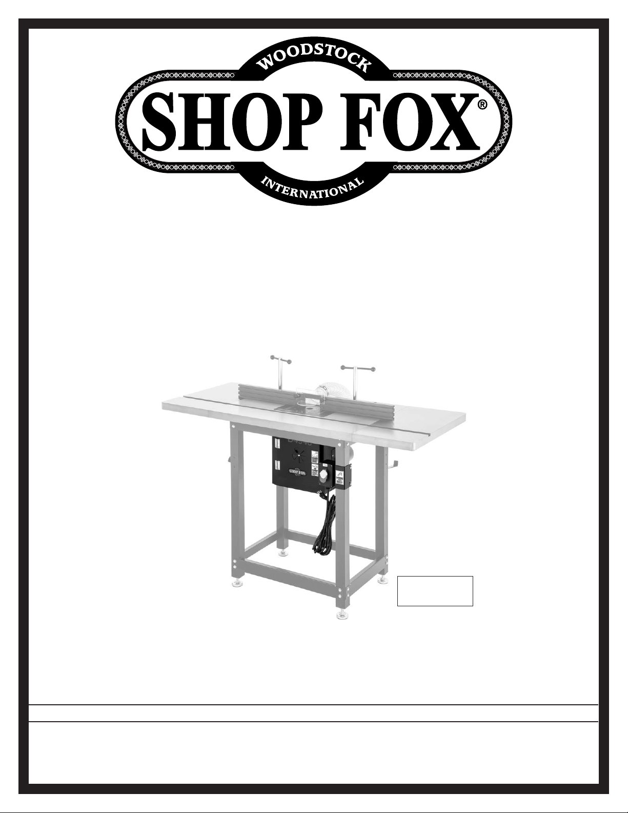
MODEL D4946
ROUTER TABLE
DUST COLLECTION ENCLOSURE
Router Table
Not Included
OWNER'S MANUAL
(FOR MODELS MANUFACTURED SINCE 11/20)
Phone: (360) 734-3482 • Online Technical Support: [email protected]
COPYRIGHT © NOVEMBER, 2020 BY WOODSTOCK INTERNATIONAL, INC.
WARNING: NO PORTION OF THIS MANUAL MAY BE REPRODUCED IN ANY SHAPE OR FORM WITHOUT
THE WRITTEN APPROVAL OF WOODSTOCK INTERNATIONAL, INC.
#21496MN Printed in Taiwan
Page 2
This manual provides critical safety instructions on the proper setup,
operation, maintenance, and service of this machine/tool. Save this
document, refer to it often, and use it to instruct other operators.
Failure to read, understand and follow the instructions in this manual
may result in fire or serious personal injury—including amputation,
electrocution, or death.
The owner of this machine/tool is solely responsible for its safe use.
This responsibility includes but is not limited to proper installation in
a safe environment, personnel training and usage authorization,
proper inspection and maintenance, manual availability and comprehension, application of safety devices, cutting/sanding/grinding tool
integrity, and the usage of personal protective equipment.
The manufacturer will not be held liable for injury or property
damage from negligence, improper training, machine modifications or
misuse.
Some dust created by power sanding, sawing, grinding, drilling, and
other construction activities contains chemicals known to the State of
California to cause cancer, birth defects or other reproductive harm.
Some examples of these chemicals are:
• Lead from lead-based paints.
• Crystalline silica from bricks, cement and other masonry products.
• Arsenic and chromium from chemically-treated lumber.
Your risk from these exposures varies, depending on how often you
do this type of work. To reduce your exposure to these chemicals:
Work in a well ventilated area, and work with approved safety equipment, such as those dust masks that are specially designed to filter
out microscopic particles.
Page 3

Contents
INTRODUCTION .................................................................................................. 2
Woodstock Technical Support
Identification
Controls & Components
SAFETY ............................................................................................................5
Standard Machinery Safety Instructions
ELECTRICAL ...................................................................................................... 7
Circuit Requirements
Grounding Requirements
Extension Cords
SETUP .............................................................................................................9
Unpacking
Items Needed for Setup
Inventory
Assembly
Connecting Power Cord
Dust Collection
Test Run
............................................................................................... 3
...................................................................................... 7
............................................................................................ 8
................................................................................................... 9
.................................................................................................... 9
................................................................................................... 10
........................................................................................... 12
.................................................................................................... 13
............................................................................ 2
................................................................................... 4
................................................................ 5
.................................................................................. 8
................................................................................... 9
................................................................................. 11
SAFETYINTRODUCTION
SETUPELECTRICAL MAINTENANCE
SERVICE ......................................................................................................... 14
Electrical Safety Instructions
Wiring Diagram
PARTS ........................................................................................................... 16
........................................................................................................ 16
Main
WARRANTY ..................................................................................................... 17
........................................................................................... 15
........................................................................... 14
OPERATIONS
SERVICE PARTS
USE THE QUICK GUIDE PAGE LABELS TO SEARCH OUT INFORMATION FAST!
Page 4

Model D4946 (For Machines Mfd. Since 11/20)
INTRODUCTION
INTRODUCTION
Woodstock Technical Support
This machine has been specially designed to provide many years of trouble-free service. Close attention
to detail, ruggedly built parts and a rigid quality control program assure safe and reliable operation.
Woodstock International, Inc. is committed to customer satisfaction. Our intent with this manual is to
include the basic information for safety, setup, operation, maintenance, and service of this product.
We stand behind our machines! In the event that questions arise about your machine, please
contact Woodstock International Technical Support at (360) 734-3482 Ext. 2 or send e-mail to:
[email protected]. Our knowledgeable staff will help you troubleshoot problems and process warranty claims.
If you need the latest edition, you can download it from http://www.woodstockint.com/manuals.
If you have comments about this manual, please contact us at:
Woodstock International, Inc.
Attn: Technical Documentation Manager
P.O. Box 2309
Bellingham, WA 98227
Email: [email protected]
-2-
Page 5
Model D4946 (For Machines Mfd. Since 11/20)
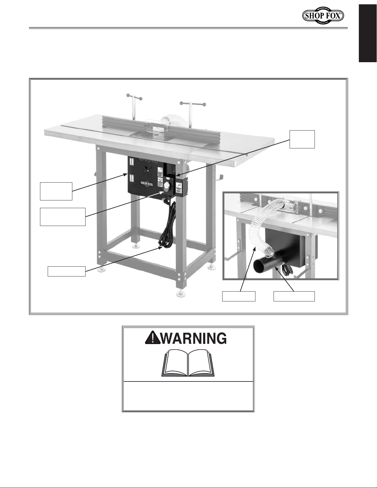
Become familiar with the names and locations of the controls and features shown below to better
Identification
INTRODUCTION
Switch
Box
Dust
Enclosure
ON/OFF
Paddle Switch
Power Cord
Dust Hose Dust Hose 4"
To reduce your risk of serious injury
or damage to the machine, read this
entire manual BEFORE using machine.
-3-
Page 6
Controls & Components
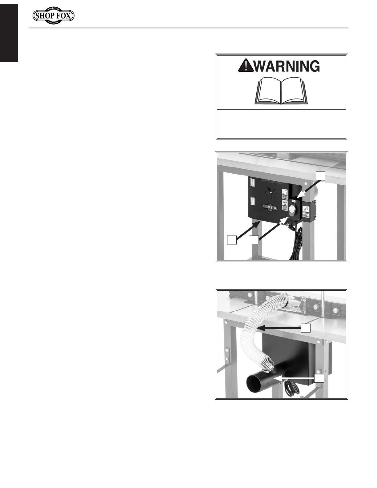
Refer to Figures 1–2 and the following descriptions to
INTRODUCTION
become familiar with the basic controls and components
of this machine. Understanding these items and how they
work will help you understand the rest of the manual and
stay safe when operating this machine.
A. Dust Enclosure. Bolts to underside of router table to
capture saw dust during operations.
Model D4946 (For Machines Mfd. Since 11/20)
To reduce your risk of serious injury
or damage to the machine, read this
entire manual BEFORE using machine.
B. ON/OFF Paddle Switch. Turns router ON and OFF.
Remove key to disable switch.
C. Switch Box. Houses 110V electrical outlet, paddle
switch, and power cord connection.
D. Dust Hose. Connects included dust port to 2 1⁄2"
outlet on user's router table fence.
E. Dust Port. 4" dust port connects to user's dust-
collection system.
C
A
Figure 1. Dust enclosure controls and
B
components (front).
D
-4-
E
Figure 2. Dust enclosure controls and
components (rear).
Page 7
Model D4946 (For Machines Mfd. Since 11/20)
SAFETY
OWNER’S MANUAL.
TRAINED OPERATORS ONLY.
DANGEROUS ENVIRONMENTS.
MENTAL ALERTNESS REQUIRED.
electrical components or improperly grounded
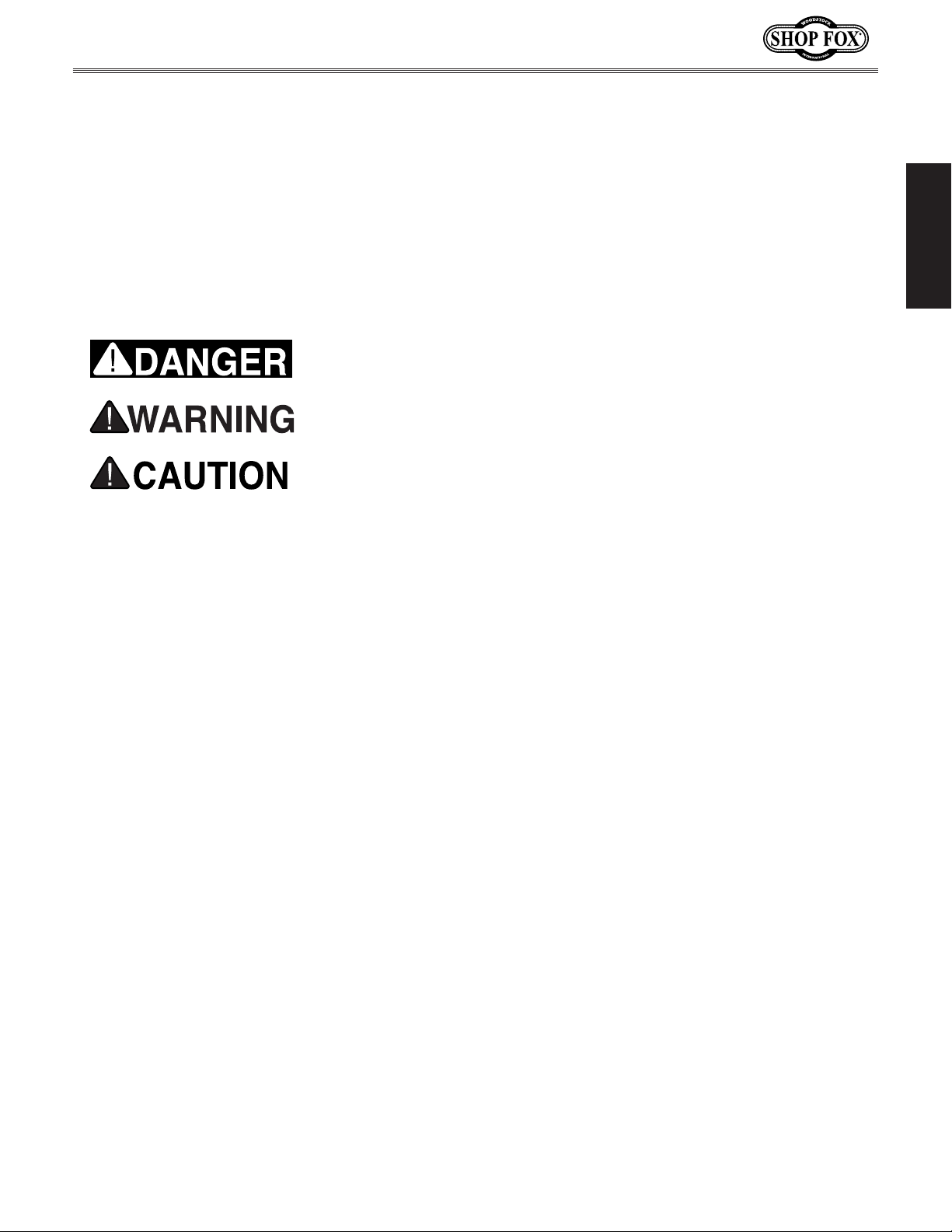
manual uses a series of symbols and signal words intended to convey the level of importance of the
safety messages. The progression of symbols is described below. Remember that safety messages by
SAFETY
For Your Own Safety,
Read Manual Before Operating Machine
The purpose of safety symbols is to attract your attention to possible hazardous conditions. This
themselves do not eliminate danger and are not a substitute for proper accident prevention measures—this responsibility is ultimately up to the operator!
NOTICE
Standard Machinery Safety Instructions
Standard Machinery Safety Instructions
Indicates an imminently hazardous situation which, if not avoided,
WILL result in death or serious injury.
Indicates a potentially hazardous situation which, if not avoided,
COULD result in death or serious injury.
Indicates a potentially hazardous situation which, if not avoided,
MAY result in minor or moderate injury.
This symbol is used to alert the user to useful information about
proper operation of the equipment or a situation that may cause
damage to the machinery.
SAFETY
Read and understand this
owner’s manual BEFORE using machine.
have a higher risk of being hurt or killed. Only
allow trained/supervised people to use this
machine. When machine is not being used,
disconnect power, remove switch keys, or
lock-out machine to prevent unauthorized
use—especially around children. Make
workshop kid proof!
machinery in areas that are wet, cluttered,
or have poor lighting. Operating machinery
in these areas greatly increases the risk of
accidents and injury.
alertness is required for safe operation of
machinery. Never operate under the influence
of drugs or alcohol, when tired, or when
distracted.
Untrained operators
Do not use
Full mental
ELECTRICAL EQUIPMENT INJURY RISKS. You can
be shocked, burned, or killed by touching live
machinery. To reduce this risk, only allow an
electrician or qualified service personnel to
do electrical installation or repair work, and
always disconnect power before accessing or
exposing electrical equipment.
DISCONNECT POWER FIRST. Always disconnect
machine from power supply BEFORE making
adjustments, changing tooling, or servicing
machine. This eliminates the risk of injury
from unintended startup or contact with live
electrical components.
EYE PROTECTION. Always wear ANSI-approved
safety glasses or a face shield when operating
or observing machinery to reduce the risk of
eye injury or blindness from flying particles.
Everyday eyeglasses are not approved safety
glasses.
-5-
Page 8

WEARING PROPER APPAREL. Do not wear
clothing, apparel, or jewelry that can become
HAZARDOUS
HEARING PROTECTION.
REMOVE ADJUSTING TOOLS.
INTENDED USAGE.
AWKWARD POSITIONS.
CHILDREN & BYSTANDERS.
GUARDS & COVERS.
FORCING MACHINERY. Do not force machine. It
will do the job safer and better at the rate for
loss of control. Before starting, verify machine
malfunction, leading to serious personal injury
from heated surfaces, high traffic areas, harsh
entangled in moving parts. Always tie back
or cover long hair. Wear non-slip footwear to
avoid accidental slips, which could cause loss
of workpiece control.
DUST. Dust created while using
SAFETY
machinery may cause cancer, birth defects,
or long-term respiratory damage. Be aware of
dust hazards associated with each workpiece
material, and always wear a NIOSH-approved
respirator to reduce your risk.
Always wear hearing
protection when operating or observing
loud machinery. Extended exposure to this
noise without hearing protection can cause
permanent hearing loss.
Tools left on
machinery can become dangerous projectiles
upon startup. Never leave chuck keys,
wrenches, or any other tools on machine.
Always verify removal before starting!
Only use machine for its
intended purpose—never make modifications
without prior approval from Woodstock
International. Modifying machine or using
it differently than intended will void the
warranty and may result in malfunction or
mechanical failure that leads to serious
personal injury or death!
Keep proper footing and
balance at all times when operating machine.
Do not overreach! Avoid awkward hand
positions that make workpiece control difficult
or increase the risk of accidental injury.
Keep children and
bystanders at a safe distance from the work
area. Stop using machine if they become a
distraction.
Model D4946 (For Machines Mfd. Since 11/20)
which it was designed.
NEVER STAND ON MACHINE. Serious injury may
occur if machine is tipped or if the cutting
tool is unintentionally contacted.
STABLE MACHINE. Unexpected movement during
operation greatly increases risk of injury or
is stable and mobile base (if used) is locked.
USE RECOMMENDED ACCESSORIES. Consult
this owner’s manual or the manufacturer for
recommended accessories. Using improper
accessories will increase risk of serious injury.
UNATTENDED OPERATION. To reduce the risk
of accidental injury, turn machine OFF and
ensure all moving parts completely stop
before walking away. Never leave machine
running while unattended.
MAINTAIN WITH CARE. Follow all maintenance
instructions and lubrication schedules to
keep machine in good working condition. A
machine that is improperly maintained could
or death.
CHECK DAMAGED PARTS. Regularly inspect
machine for any condition that may affect
safe operation. Immediately repair or replace
damaged or mis-adjusted parts before
operating machine.
MAINTAIN POWER CORDS. When disconnecting
cord-connected machines from power, grab
and pull the plug—NOT the cord. Pulling the
cord may damage the wires inside, resulting
in a short. Do not handle cord/plug with wet
hands. Avoid cord damage by keeping it away
chemicals, and wet/damp locations.
accidental contact with moving parts or flying
debris—make sure they are properly installed,
undamaged, and working correctly.
Guards and covers reduce
EXPERIENCING DIFFICULTIES. If at any time
you experience difficulties performing the
intended operation, stop using the machine!
-6-
Contact Technical Support at (360) 734-3482.
Page 9
Model D4946 (For Machines Mfd. Since 11/20)
This machine must be connected to the correct size and
type of power supply circuit, or fire or electrical damage
may occur. Read through this section to determine if an
adequate power supply circuit is available. If a correct
circuit is not available, a qualified electrician MUST install
one before you can connect the machine to power.
A power supply circuit includes all electrical equipment
between the breaker box or fuse panel in the building
and the machine. The power supply circuit used for
this machine must be sized to safely handle the fullload current drawn from the machine for an extended
period of time. (If this machine is connected to a circuit
protected by fuses, use a time delay fuse marked D.)
This machine is prewired to operate on a power supply
circuit that has a verified ground and meets the following
requirements:
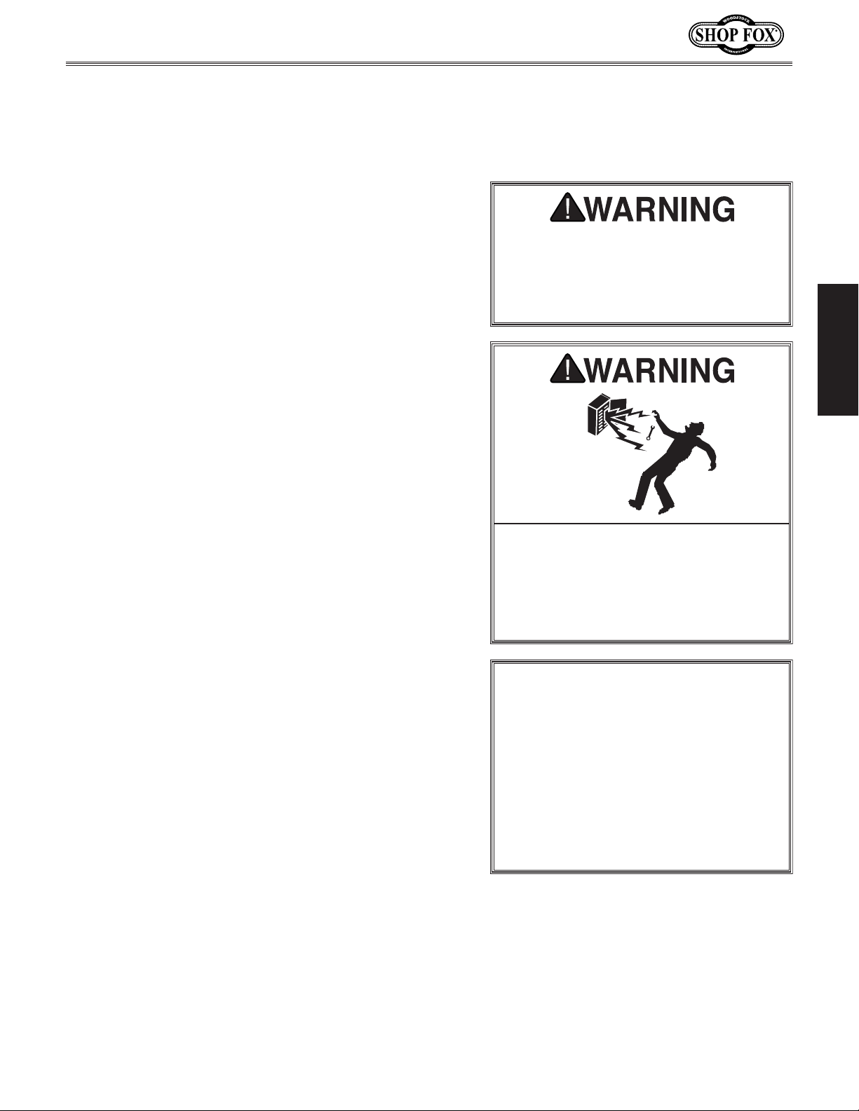
or machine damage. To reduce this risk,
where only one machine will be running
multiple machines will be running at the
ELECTRICAL
Circuit Requirements
The machine must be properly set up
before it is safe to operate. DO NOT
connect this machine to the power
source until instructed to do so later
in this manual.
ELECTRICAL
Circuit Requirements for 110V
Circuit Type ............... 110V/120V, 60 Hz, Single-Phase
Circuit Size ............................................. 15 Amps
Plug/Receptacle .................................... NEMA 5-15
Incorrectly wiring or grounding this
machine can cause electrocution, fire,
only an electrician or qualified service
personnel should do any required
electrical work on this machine.
NOTICE
The circuit requirements listed in this
manual apply to a dedicated circuit—
at a time. If this machine will be
connected to a shared circuit where
same time, consult with an electrician
to ensure that the circuit is properly
sized for safe operation.
-7-
Page 10
Grounding Requirements
This machine MUST be grounded. In the event of certain
types of
a path of least resistance for electric current
order
Improper connection of the equipment-grounding
will
increase
insulation
grounding
cord or plug is necessary, do not connect the equipmentgrounding
Check with a qualified electrician or service personnel
if
or if
properly grounded.
plug is damaged or worn, disconnect it from power, and
immediately replace it with a new one.
We do not recommend using an extension cord with
Any extension cord used with this machine must contain a
plug and receptacle, and
meet the following requirements:
This machine is equipped with a power cord with an
equipment-grounding
plug
a matching
grounded in accordance with local codes and ordinances.
Model D4946 (For Machines Mfd. Since 11/20)
malfunctions or breakdowns, grounding provides
to reduce the risk of electric shock.
the risk of electric shock. The wire with green
(with/without yellow stripes) is the equipment-
wire. If repair or replacement of the power
wire to a live (current carrying) terminal.
you do not understand these grounding requirements,
you are in doubt about whether the tool is
ELECTRICAL
For 110V Connection
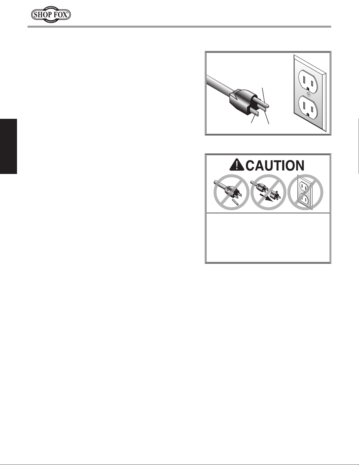
(see figure). The plug must only be inserted into
receptacle that is properly installed and
to travel—in
wire
If you ever notice that a cord or
wire and NE M A 5-15 grounding
110V
5-15 PLUG
Figure 3. NEMA 5-15 plug & receptacle.
DO NOT modify the provided plug or
use an adapter if the plug will not
fit the receptacle. Instead, have an
electrician install the proper receptacle
on a power supply circuit that meets
the requirements for this machine.
GROUNDED
5-15 RECEPTACLE
Grounding Pin
Neutral Hot
Extension Cords
this machine. Extension cords cause voltage drop, which
may damage electrical components and shorten motor
life. Voltage drop increases with longer extension cords
and smaller gauge sizes (higher gauge numbers indicate
smaller sizes).
ground wire, match the required
Minimum Gauge Size at 110V ...................... 14 AWG
Maximum Length (Shorter is Better) ................50 ft.
-8-
Page 11
Model D4946 (For Machines Mfd. Since 11/20)
This machine has been carefully packaged for safe
transportation. If you notice the machine has been
damaged during shipping, please contact your authorized
Shop Fox dealer immediately.
The following items are needed, but not included, to set
up your machine.
This machine presents
serious injury hazards
to untrained users. Read
to become familiar with
tions before starting the
The following is a list of items shipped with your machine.
Before beginning setup, lay these items out and inventory
them.
Note:
check around/inside the machine and packaging materials.
Often, these items get lost in packaging materials while
unpacking or they are pre-installed at the factory.
SETUP
Unpacking
through this entire manual
the controls and opera-
Items Needed for Setup
Description Qty
• Phillips Head Screwdriver #1 ............................1
• Open-End Wrench or Socket 12mm .....................1
• Disposable Rags for Cleaning ................ As Needed
Inventory
If you cannot find an item on this list, carefully
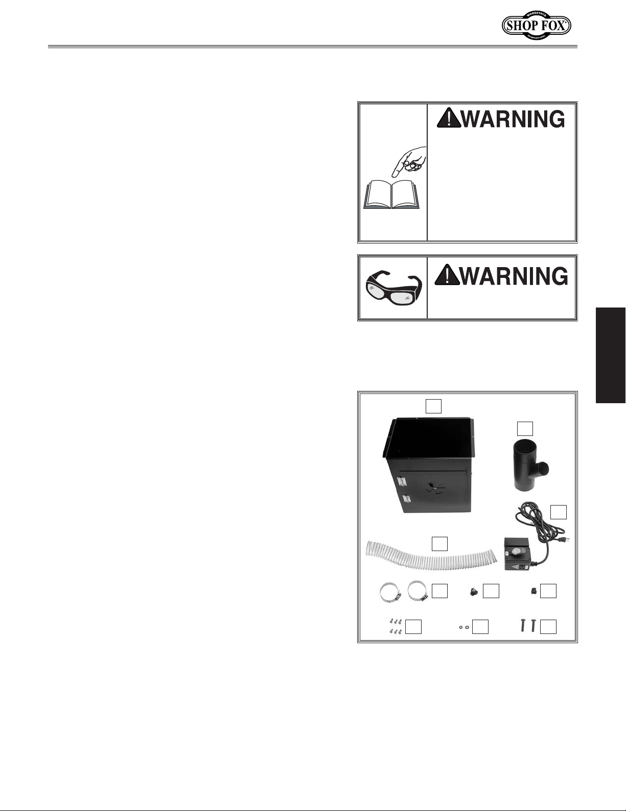
Box Contents (Figure 4): Qty
A. Dust Enclosure .............................................1
B. Y-Fitting 4" x 4" x 21⁄2" ....................................1
Switch Box ..................................................1
C.
D. Dust Hose 21⁄2" x 28" ......................................1
E. Strain Relief 1⁄2" ...........................................1
Star Knob 1⁄4"-20 x 1⁄2" ....................................1
F.
Hose Clamps 3" ............................................2
G.
Hex Bolts 1⁄4"-20 x 21⁄2" ..................................2
H.
I. Flat Washers 1⁄4" ...........................................2
J. Phillip Head Screws 10-24 x 3⁄8".........................6
machine!
Wear safety glasses during
entire setup process!
SETUP
A
B
C
D
EFG
HIJ
Figure 4. Inventory.
-9-
Page 12
Model D4946 (For Machines Mfd. Since 11/20)
Before beginning the assembly process, refer to Items
Needed for Setup
Ensure all parts have been properly cleaned of any
heavy-duty rust-preventative applied at the factory (if
applicable). Be sure to complete all steps in the assembly
procedure prior to performing the
or connecting
the machine to power.
Assembly
and gather everything you need.
Test Run
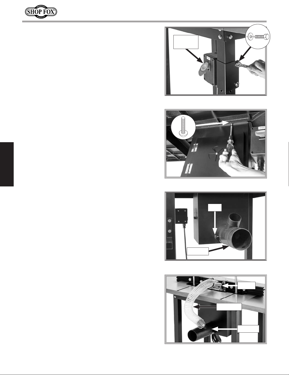
To install switch box and dust enclosure, do these steps:
1. Attach switch box (see Figure 5) to leg of your
router table stand with pre-installed clamp and (2)
1
⁄4" -20 x 21⁄2" hex bolts and (2) 1⁄4" flat washers.
2. Install dust enclosure (see Figure 6) underneath
your router table with (6) 10-24 x
screws.
Note: The vent should be facing the front of your
table.
SETUP
3
⁄8" Phillips head
Electrical
Box
Figure 5. Attaching switch box to a stand.
x 6
x 2
3. Install Y-fitting (see Figure 7) on dust port and
secure with (1)
4. Attach 2 1⁄2" dust hose (see Figure 8) on Y-fitting and
the dust shroud on your router table fence. Secure
with 3" hose clamps.
1
⁄4" -20 x 1⁄2" knob.
Figure 6. Attaching dust enclosure to table.
Knob
Y-Fitting
Figure 7. Y-fitting attached to dust port.
Shroud
Dust Hose
Y-Fitting
Figure 8. Example of dust hose connecting
Y-fitting and fence dust shroud.
-10-
Page 13
Model D4946 (For Machines Mfd. Since 11/20)
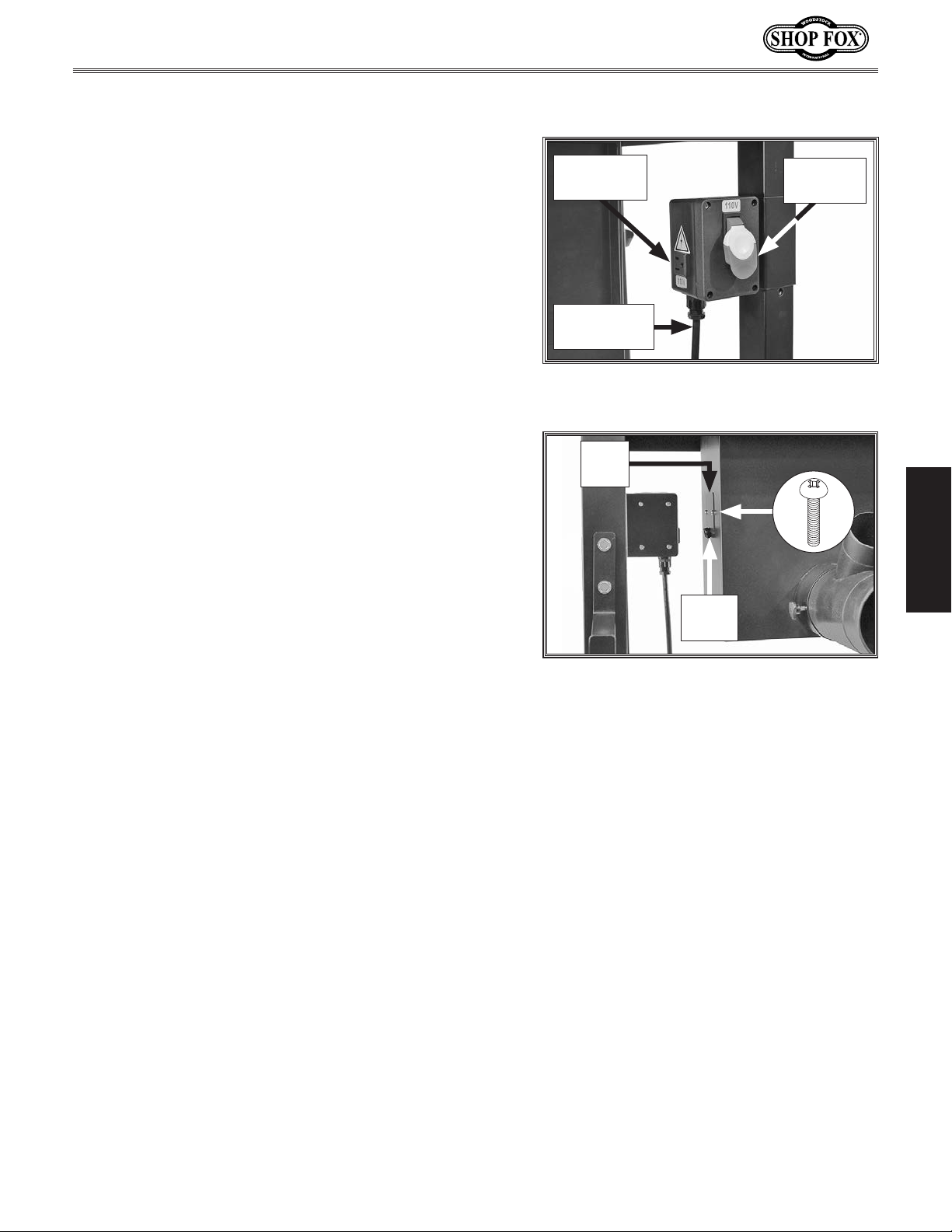
Connecting Power Cord
The Model D4946 includes a switch box with a 110V
receptacle and an ON/OFF paddle switch (see Figure
9). The router power cord can be plugged into the 110V
receptacle, and the power cord on the switch box can be
plugged into a 110V outlet. This allows you to start and
stop your router without having to reach into the dust
enclosure for the router ON/OFF switch.
110V
Receptacle
ON/OFF
Switch
To connect router and router table to power, do these
steps:
1. Ensure paddle switch is set to OFF position.
2. Loosen (2) 10-24 x 3⁄8" Phillips head screws (see
Figure 10) securing side door on dust enclosure, and
feed router power cord through opening.
3. Plug router power cord into 110V receptacle on
switch box.
4. Plug switch box power cord into matching power
supply outlet.
5. Install 1⁄2" strain relief (see Figure 10) on router
power cord where it emerges from dust enclosure
side door and secure by tightening screws.
Switch Box
Power Cord
Figure 9. Location of ON/OFF switch and
110V receptacle.
Side
Door
x 2
Strain
Relief
Figure 10. Location of dust enclosure side
door.
SETUP
-11-
Page 14
Dust Collection
Do not confuse this CFM recommendation with the rating
of the dust collector. To determine the CFM at the dust
port, you must consider these variables: (1) CFM rating of
the dust collector, (2) hose type and length between the
dust collector and the machine, (3) number of branches
or wyes, and (4) amount of other open lines throughout
the system. Explaining how to calculate these variables
is beyond the scope of this manual. Consult an expert or
purchase a good dust collection “how-to” book.
Recommended CFM at Dust Port: ................ 400 CFM
This machine creates substantial amounts of dust
during operation. Breathing airborne dust on a regular basis can result in permanent respiratory illness.
Reduce your risk by wearing a respirator and capturing the dust with a dust collection system.
Model D4946 (For Machines Mfd. Since 11/20)
SETUP
Tools Needed Qty
Dust Collection System
Dust Hose 4"
Hose Clamps 4"
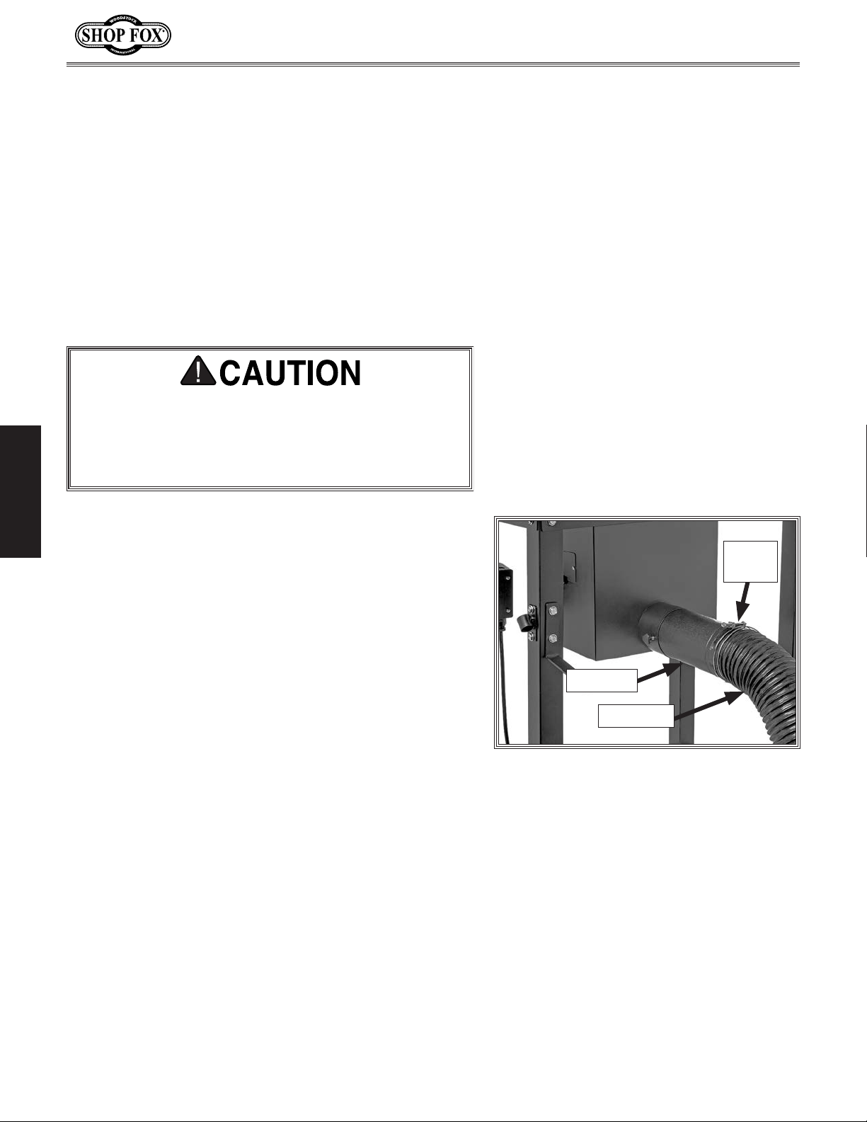
To connect a dust collection hose, do these steps:
1. Fit a 4" dust hose over dust port, as shown in Figure
11, and secure it in place with a hose clamp.
Tug hose to make sure it does not come off.
2.
Note: A tight fit is necessary for proper
performance.
.....................................................1
..................................................2
........................................1
Hose
Clamp
Y-Fitting
Dust Hose
Figure 11. Example of 4" dust hose
connected to Y-fitting.
-12-
Page 15
Model D4946 (For Machines Mfd. Since 11/20)
performed. Operating an improperly set
Once assembly is complete, test run the machine to
ensure it is properly connected to power and safety
components are functioning properly.
If you find an unusual problem during the test run,
immediately stop the machine, disconnect it from power,
and fix the problem BEFORE operating the machine again.
The
section of this
manual can help.
Test Run
Troubleshooting table in the SERVICE
The Test Run consists of verifying the following: 1) The
motor powers up and runs correctly, and 2) the switch
disabling key disables the switch properly.
To test run the machine, do these steps:
Serious injury or death can result
from using this machine BEFORE
understanding its controls and related
safety information. DO NOT operate, or
allow others to operate, machine until
the information is understood.
DO NOT start machine until all
preceding setup instructions have been
1. Clear all setup tools away from router table.
Make sure paddle switch is set to OFF position.
2.
3. Make sure router power cord is plugged into 110V
receptacle in switch box.
Connect router table power cord to power supply.
4.
5. Reach into dust enclosure and turn router ON.
Using paddle switch, turn router table ON, verify
6.
router powers up, and then turn router table OFF.
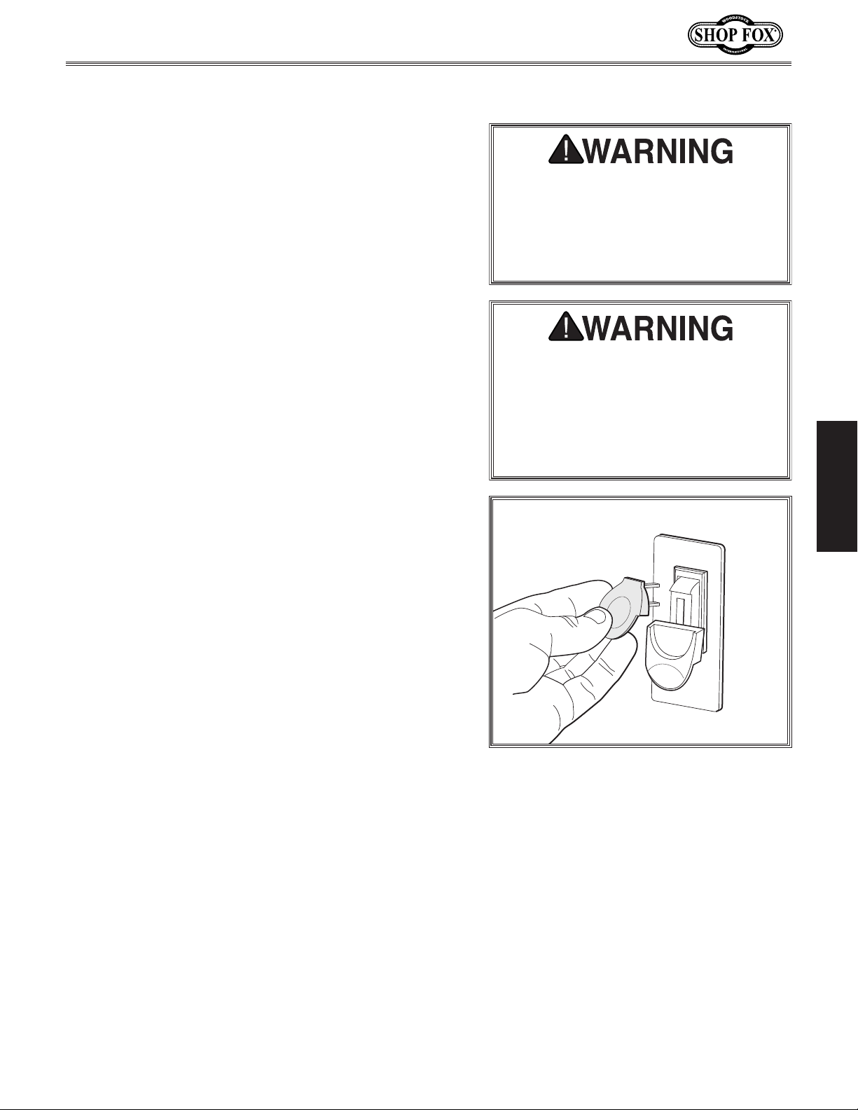
7. Remove switch-disabling key, as shown in Figure 12.
Try to start router with paddle switch. The router
8.
should not start.
— If router does not start, switch disabling feature is
working as designed.
up machine may result in malfunction
or unexpected results that can lead
to serious injury, death, or machine/
property damage.
Figure 12. Removing switch key from
paddle switch.
SETUP
— If router does start, immediately stop router. The
switch disabling feature is not working correctly.
This safety feature must work properly before
proceeding with regular operations.
Re-install switch-disabling key in paddle switch.
9.
Congratulations! The test run is complete. The
router table is ready for operation.
-13-
Page 16
Model D4946 (For Machines Mfd. Since 11/20)
These pages are current at the time of printing. However, in the spirit of improvement, we may make
changes to the electrical systems of future machines. Compare the manufacture date of your machine to
If there are differences between your machine and what is shown in this section, call Technical Support
for assistance BEFORE making any changes to the wiring on your machine. An updated
machine before calling. This information can be found on the main machine label.
SERVICE
Electrical Safety Instructions
the one stated in this manual, and study this section carefully.
at (360) 734-3482
wiring diagram may be available. Note: Please gather the serial number and manufacture date of your
SHOCK HAZARD. Working on wiring that is
connected to a power source is extremely
dangerous. Touching electrified parts will
result in personal injury including but not
limited to severe burns, electrocution,
or death. Disconnect the power from
the machine before servicing electrical
components!
QUALIFIED ELECTRICIAN. Due to the inherent
hazards of electricity, only a qualified
electrician should perform wiring tasks on
this machine. If you are not a qualified
electrician, get help from one before
attempting any kind of wiring job.
WIRE CONNECTIONS. All connections must
be tight to prevent wires from loosening
during machine operation. Double-check all
wires disconnected or connected during any
wiring task to ensure tight connections.
WIRE/COMPONENT DAMAGE. Damaged wires
or components increase the risk of serious
personal injury, fire, or machine damage. If
you notice that any wires or components are
damaged while performing a wiring task,
replace those wires or components before
completing the task.
MODIFICATIONS. Using aftermarket parts or
modifying the wiring beyond what is shown
in the diagram may lead to unpredictable
results, including serious injury or fire.
MOTOR WIRING. The motor wiring shown
in these diagrams is current at the time
of printing, but it may not match your
machine. Always use the wiring diagram
inside the motor junction box.
CAPACITORS/INVERTERS. Some capacitors
and power inverters store an electrical
charge for up to 10 minutes after being
disconnected from the power source.
To reduce the risk of being shocked,
wait at least this long before working on
capacitors.
CIRCUIT REQUIREMENTS. You MUST follow
the requirements at the beginning of this
manual when connecting your machine to a
power source.
EXPERIENCING DIFFICULTIES. If you are
experiencing difficulties understanding
the information included in this section,
contact our Technical Support at
(360) 734-3482.
SERVICE
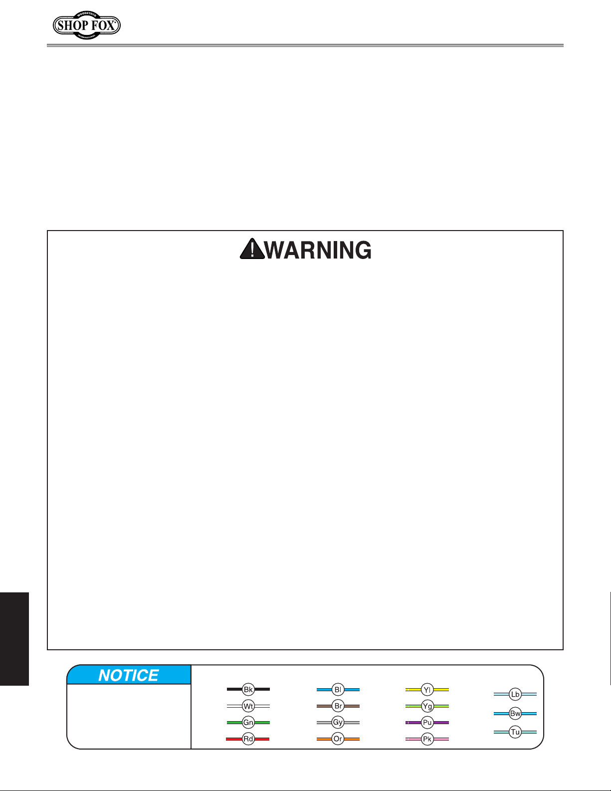
WIRING DIAGRAM COLOR KEY
The photos and diagrams
included in this section are
best viewed in color. You
can view these pages in
color at www.shopfox.biz.
BLACK
WHITE
GREEN
RED
BLUE
BROWN
GRAY
ORANGE
-14-
YELLOW
YELLOW
GREEN
PURPLE
PINK
LIGHT
BLUE
BLUE
WHITE
TURQUOISE
Page 17
Model D4946 (For Machines Mfd. Since 11/20)
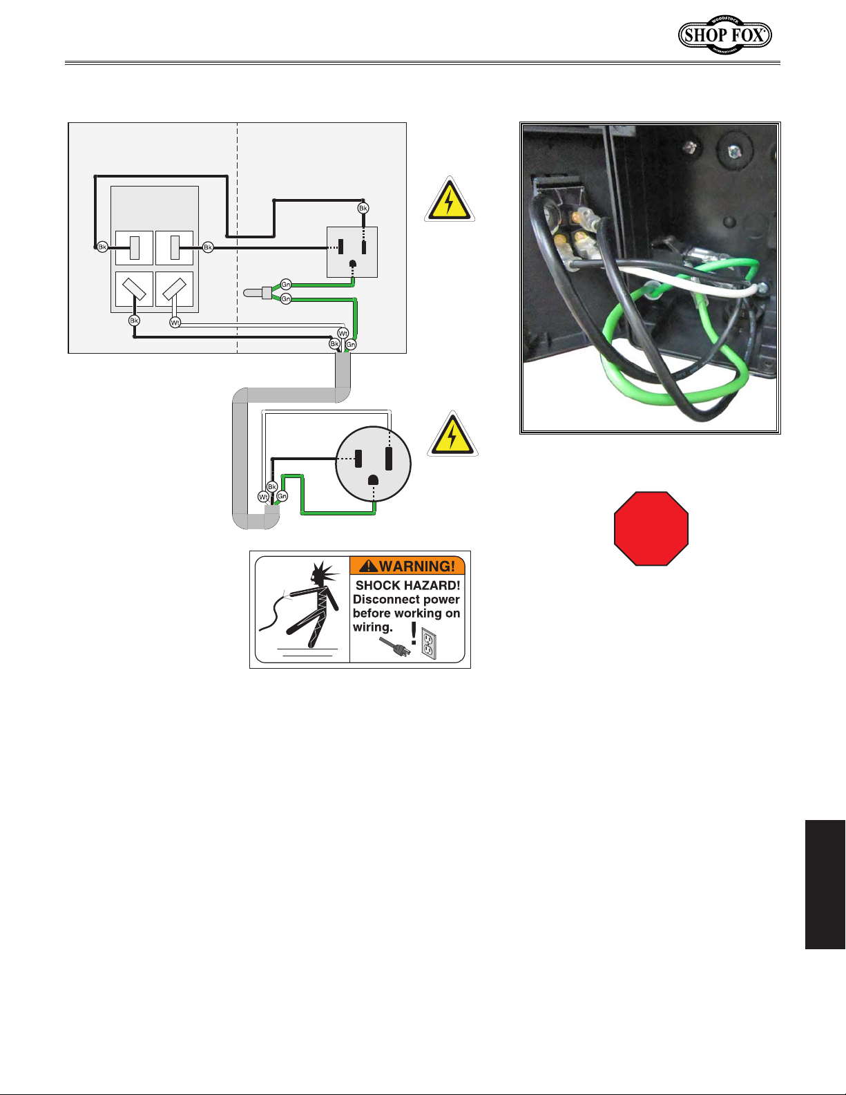
Wiring Diagram
ON/OFF PADDLE SWITCH
J1708W2 125V
Hot
Neutral
Ground
Neutral
110 VAC
5-15
Receptacle
Hot
Ground
110 VAC
5-15 Plug
Figure 13. ON/OFF switch and 110V
outlet wiring.
Read
Page 14
STOP
Before
Wiring
SERVICE
-15-
Page 18
Model D4946 (For Machines Mfd. Since 11/20)
PARTS
Main
13
26
20
12
15
19
16
21
1
6
22
25
23
WARNING!
READ and UNDERSTAND
MANUAL to avoid serious
injury! If a manual is not
available, DO NOT use
machine! Instead, go to
www.woodstockint.com
or call
(
360
)
734-3482.
WARNING!
INJURY HAZARD!
To reduce risk of shortand long-term injury,
wear safety glasses,
hearing protection, and
a respirator when using
this machine.
2
4
3
24
11
8
8
7
9
10
5
17
WARNING
ACCIDENTAL INJURY
HAZARD!
Disconnect power
supply before
adjustments, setup
or maintenance!
18
10
14
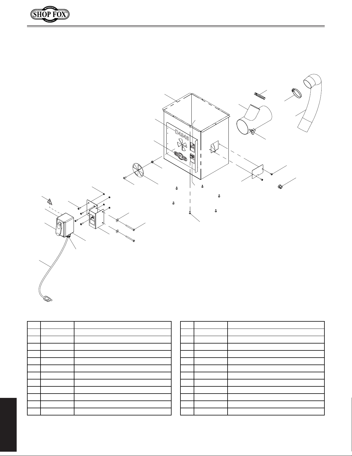
REF PAR T # DESCRIPTION REF PAR T # DESCRIPTION
1 XD4946001 DUST ENCLOSURE 14 XD4946014 SWITCH BRACKET
2 XD4946002 LOCK NUT 1/4-20 15 XD4946015 PHLP HD SCR 10-24 X 5/8
3 XD4946003 DUST BOX VENT PLATE 16 XD4946016 LOCK NUT 10-24
4 XD4946004 BUTTON HD CAP SCR 1/4-20 X 1/2 17 XD4946017 FLAT W ASHER 1/4
5 XD4946005 STRAIN RELIEF TYP E-1 1/2 18 XD4946018 HEX BOLT 1/4-20 X 2-1/2
6 XD4946006 Y-FITTING 4" X 4" X 2-1/2" 19 XD4946019 STRAIN RELIEF TYPE-3 M16-2
7 XD4946007 DUST HOSE 2-1/2" X 28" 20 XD4946020 ELECTRICAL OUTLET 15A 125V
8 XD4946008 WIRE HOSE CLAMP 3" 21 XD4946021 SWITCH BOX
9 XD4946009 KNOB BOLT 1/4- 20 X 1/2, 3-LOBE, D1 22 XD4946022 MODEL NUMBER LABEL
10 XD4946010 PHLP H D SCR 10-24 X 3/8 23 XD4946023 SHOP FOX LOGO
11 XD4946011 CORD CLAMP PLATE 24 XD4946024 EYE EAR LUNG HAZARD LABEL
12 XD4946012 PADDLE SWITCH J1708W2 125VAC 25 XD4946025 READ MANUAL LABEL
13 XD4946013 POWER CORD 14G 3W 72" 5- 15P 26 XD4946026 ELECTRICITY LABEL
PARTS
-16-
Page 19

warranty does not apply to defects due directly or indirectly to misuse, abuse, negligence or accidents,
WARRANTY
WARRANTY
Woodstock International, Inc. warrants all Shop Fox machinery to be free of defects from workmanship
and materials for a period of two years from the date of original purchase by the original owner. This
lack of maintenance, or reimbursement of third party expenses incurred.
Woodstock International, Inc. will repair, replace, or arrange for a dealer refund, at its expense and
option, the Shop Fox machine or machine part proven to be defective for its designed and intended
use, provided that the original owner returns the product prepaid to an authorized warranty or repair
facility as designated by our Bellingham, Washington office with proof of their purchase of the product
within two years, and provides Woodstock International, Inc. reasonable opportunity to verify the
alleged defect through inspection. If it is determined there is no defect, or that the defect resulted
from causes not within the scope of Woodstock International Inc.'s warranty, then the original owner
must bear the cost of storing and returning the product.
This is Woodstock International, Inc.’s sole written warranty and any and all warranties that may be
implied by law, including any merchantability or fitness, for any particular purpose, are hereby limited
to the duration of this written warranty. We do not warrant that Shop Fox machinery complies with
the provisions of any law, acts or electrical codes. We do not reimburse for third party repairs. In no
event shall Woodstock International, Inc.’s liability under this limited warranty exceed the purchase
price paid for the product, and any legal actions brought against Woodstock International, Inc. shall be
tried in the State of Washington, County of Whatcom. We shall in no event be liable for death, injuries
to persons or property or for incidental, contingent, special or consequential damages arising from the
use of our products.
Every effort has been made to ensure that all Shop Fox machinery meets high quality and durability
standards. We are commited to continuously improving the quality of our products, and reserve the
right to change specifications at any time.
To register the warranty, go to https://www.woodstockint.com/warranty, or scan the QR code below.
You will be directed to the Warranty Registration page on www.woodstockint.com. Enter all applicable
production information.
WARRANTY
WOODSTOCKINT.COM
Page 20

 Loading...