

Shimano ALFINE SL-S500 - TECHNICAL, Alfine SL-S500, Alfine CJ-8S20 Service Instructions Manual
Page 1
CJ-8S20
JAPAN
LOCK
CJ-8S20
JAPAN
LOCK
CJ-8S20
JAPAN
LOCK
SI-6M20A
SL-S500
CJ-8S20
Shifting Lever
Cassette Joint
CJ-8S20
JAPAN
LOCK
2 mm Allen key
or #14 spoke
Pulley hole
Turn the
pulley
Pull out from
the outer
casing holder
CJ-8S20
JAPAN
LOCK
3
1
Remove the inner
cable fixing bolt unit
2
CJ-8S20
JAPAN
LOCK
CJ-8S20
JAPAN
LOCK
CJ-8S20
JAPAN
CJ-8S20
JAPAN
LOCK
CJ-8S20
JAPAN
LOCK
2
1
1
2
3
CJ-8S20
JAPAN
LOCK
CJ-8S20
JAPAN
LOCK
CJ-8S20
JAPAN
LOCK
CJ-8S20
JAPAN
LOCK
Be sure to shift the lever one gear at a time, and
reduce the force being applied to the pedals
during shifting. If you try to force operation of the
shifting lever while the pedals are being turned
strongly, your feet may come off the pedals and
the bicycle may topple over, which could result
in serious injury.
Indicator
General Safety Information
CAUTION
WARNING
– To avoid serious injuries:
– To avoid serious injuries:
NOTE:
For maximum performance we highly
recommend Shimano lubricants and
maintenance products.
Parts are not guaranteed against natural wear
or deterioration resulting from normal use.
Obtain and read the service instructions
carefully prior to installing the parts. Loose,
worn, or damaged parts may cause serious
injury to the rider.
We strongly recommend only using genuine
Shimano replacement parts.
Read these Technical Service Instructions
carefully, and keep them in a safe place for
later reference.
Technical Service Instructions
Be sure to read these service instructions in
conjunction with the service instructions for
the SG-S500 hub or Inter-8 hub before use.
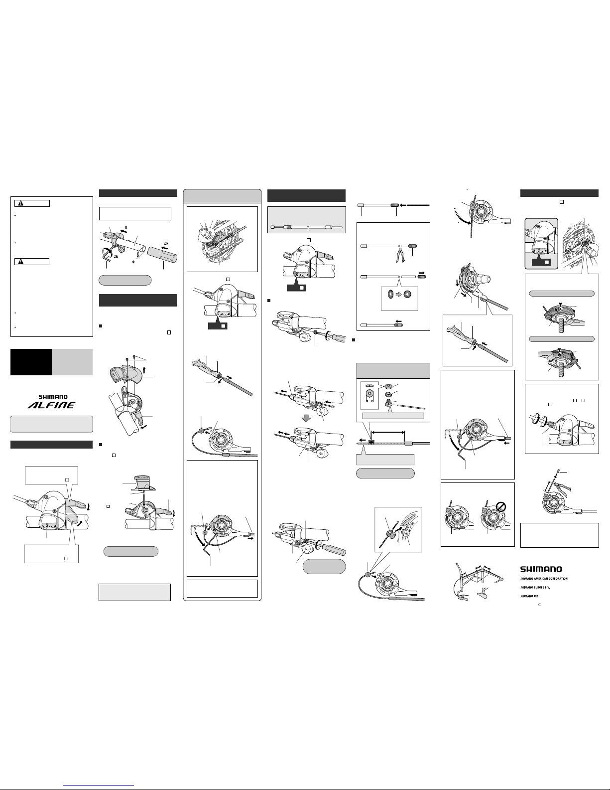
Shifting lever operation
After you release your finger from lever A /lever B once
shifting is complete, the lever will always return to its
original position.
Tighten
Handlebar
Grip
5 mm Allen key
Clamp bolt
22.2 mm
Tightening torque:
5 – 7 N·m {50 – 70 kgf·cm}
Tightening torque:
0.3 – 0.5 N·m {3 – 5 kgf·cm}
Tightening torque:
3.5 – 5.5 N·m {35 – 55 kgf·cm}
Installation of the shifting lever
Install the shifting lever as shown in the illustration.
Use a handlebar grip with a maximum outer
diameter of 32 mm.
Cover fixing screws
Indicator unit
Lever B
Pin of change plate
Lever B
Indicator unit
Hole in winder unit
( position)
Note:
If reusing the cable, refer to steps 7 to 9 in
"Installation of the shifting cable".
Do not disassemble the indicator unit or the
shifting lever unit. Disassembling them may
result in malfunctions.
1
Set the shifting lever to .
Pull the outer casing out from the outer
casing holder of the cassette joint, and then
remove the inner cable from the slit in the
bracket.
Remove the inner cable fixing bolt unit from
the cassette joint pulley.
Disconnecting the shifting cable when
removing the rear wheel from the frame
Cassette joint
Inner cable fixing bolt unit
Cassette joint pulley
Remove from
the slit
Pull out from outer
casing holder
Bracket
Wire end hooking cap
Hole in cable adjustment bolt
Groove in winder unit
Hole in winder unit
Inner cable drum
Wire end hooking cap
unit cover
Lever A
Slit
If it is difficult to pull the outer casing out
from the outer casing holder of the cassette
joint, insert a 2 mm Allen key or a #14
spoke into the hole in the cassette joint
pulley, and then turn the pulley to loosen
the inner cable. Then remove the inner
cable fixing bolt unit from the pulley first,
and after this remove the outer casing from
the outer casing holder.
Outer casing holder
CJ-8S20
JAPAN
2
1
Installation of the shifting
cable
Use a shifting cable with one inner cable drum.
Cable with one inner cable drum:
SIS-SP41/SP40 (4 mm dia.)
Replacement and assembly
of the indicator unit
Shifting lever side
Operate lever B 7 times or more to set it to .
Removal
101 mm
Gap in pulley
Bring the cable around to the cassette joint pulley,
hold so that the inner cable fixing nut is facing to
the outside (toward the fork end), and then slide
the flats part of the inner cable fixing washer into
the gap in the pulley.
Flats part of inner
cable fixing washer
Inner cable
fixing nut
Pulley
After checking that the end of the outer casing is
sitting securely in the cable adjustment bolt of the
shifting lever, attach the inner cable fixing bolt unit
to the inner cable.
Cassette joint side
Inner cable fixing bolt unit
Note: Do not use this inner cable fixing bolt
unit with the CJ-4S30 cassette joint.
Inner cable fixing nut
Inner cable fixing
washer
Inner cable fixing bolt
Pass the inner cable through the hole.
Pull the inner cable while attaching
the inner cable fixing bolt unit.
Pulley
Bracket
Guide
OK Not OK
Secure the cable to the frame with the outer
casing bands.
10 cm
10 cm
15 cm
Turn the
cable 60
Hook
Turn the cable 60 counterclockwise and attach it
to the hook.
Attach the inner cable to the pulley as shown in
the illustration, pass the inner cable through the
slit in the cassette joint bracket, and then insert
the end of the outer casing securely into the outer
casing holder.
Inner cable
Slit
Outer casing holder
Pass through
the slit.
Note:
Check that the inner cable is correctly seated
inside the pulley guide.
If first inserting the outer casing into the
outer casing holder is easier, then first insert
the outer casing into the outer casing holder,
and then insert a 2 mm Allen key or a #14
spoke into the hole in the cassette joint
pulley, and then turn the pulley so that the
inner cable fixing bolt unit fits into the gap in
the pulley.
Hole in pulley
Insert into the
outer casing
holder
Insert the inner cable
fixing bolt unit
Guide
Outer casing bands
Bracket
Insert into the
outer casing
holder.
2 mm Allen key
or #14 spoke
Turn the
pulley
These service instructions explain how to use and
maintain the Shimano bicycle parts which have been
used on your new bicycle. For any questions regarding
your bicycle or other matters which are not related to
Shimano parts‚ please contact the place of purchase or
the bicycle manufacturer.
Adjusting the cassette joint
Set the shifting lever to .
Check to be sure that the yellow setting lines on
the cassette joint bracket and pulley are aligned at
this time.
After adjusting the cassette joint, cut off the
excess length of inner cable and then install the
inner end cap.
4
Cable adjustment bolt
Cassette joint
pulley
Cassette joint
pulley
Yellow setting lines
15 – 20 mm
Should be straight
Should be straight
When bicycle is upside down
When bicycle is standing up
If the yellow setting lines are not aligned, turn
the cable adjustment bolt of the shifting lever
to align the setting lines. After this, move the
shifting lever once more from to and
then back to , and then re-check to be
sure that the yellow setting lines are aligned.
These service instructions are printed on recycled paper.
Please note: Specifications are subject to change for improvement
without notice. (English)
The yellow setting lines on the cassette joint
are located in two places. Use the one that
is easiest to see.
Cassette joint bracket
Cassette joint bracket
Pass the inner cable through the SIS-SP41/ SP40
outer casing through the end with the plastic cap.
If cutting the outer casing, cut it near the end
with the plastic cap while the cap is still
attached. Then make the cut end perfectly
round and attach the plastic cap.
(Lever side)
Remove the plastic cap.
Make the cut end
perfectly round.
Attach the plastic cap.
Aluminum cap
Plastic cap
Plastic cap
Disassembly and assembly should only be carried
out when removing and replacing the indicator unit.
1
Set the shifting lever to .
4
1 4
1
Pedaling becomes lighter.
Lever B:
(Indicator moves toward )
8
Pedaling becomes heavier.
Lever A:
(Indicator moves toward )
Set to
1
Set to
1
May 2006 by Shimano Inc. PIT. SZK. Printed in Japan
C
1.
1.
1.
Loosen and remove the wire end hooking cap.
2.
Insert the inner cable into the groove in the winder
unit, and then pass it through the hole in the cable
adjustment bolt. Next, pull the inner cable so that
the inner cable drum fits into the hole in the
winder unit.
3.
Screw in the wire end hooking cap as shown in
the illustration until it stops. If it is turned any
further, it will damage the screw thread in the
cover.
In addition, the unit cover may become bent,
which may cause an obstruction between the unit
cover and lever A, and lever A may not operate
correctly. If lever A does not return properly,
loosen the wire end hooking cap slightly to make
a gap between lever A and the unit cover, and
check that this improves the returning of lever A.
4.
5. 8.
1.
2.
9.
10.
6.
7.
2.
3.
Check that the needle of the indicator is on the left
side ( position), and then install the indicator
unit so that it is facing straight upward. Insert the
pin of the change plate that is protruding from the
bottom of the indicator unit into the hole in the
winder unit at this time.
Installation
4.
Loosen and remove the two cover fixing screws
which are securing the indicator unit.
2.
Remove the indicator unit as shown in the
illustration.
3.
Secure the indicator unit with the two cover fixing
screws.
5.
Operate lever A and lever B, and check their
operation. If they do not operate correctly, reinstall
the indicator unit while taking particular note of
step 4. above.
6.
1
1
1
Disconnect the cable from the cassette joint
when removing the rear wheel from the
frame.
Tightening torque:
0.3 – 0.5 N·m
{3 – 5 kgf·cm}
10 mm
Inner end cap
One Holland, Irvine, California 92618, U.S.A. Phone: +1-949-951-5003
Industrieweg 24, 8071 CT Nunspeet, The Netherlands Phone: +31-341-272222
3-77 Oimatsu-cho, Sakai-ku, Sakai, Osaka 590-8577, Japan
Set to
4
 Loading...