

Shimano Alfine S7000 Series Dealer's Manual

(English)
DM-SG0004-02
Dealer's Manual
ROAD MTB Trekking
City Touring/
Comfort Bike
URBAN SPORT E-BIKE
S7000 series
Inter-11
Inter-8

2
CONTENTS
IMPORTANT NOTICE .............................................................................................. 3
TO ENSURE SAFETY ............................................................................................... 4
LIST OF TOOLS TO BE USED ................................................................................ 10
INSTALLATION ..................................................................................................... 12
Installation of the CS-S500 sprocket with chain guard ............................................................................12
Installation of the cassette joint to the hub .............................................................................................13
Installation of the disc brake rotor ...........................................................................................................15
Installation of the hub to the frame .........................................................................................................16
Installation of the shifting lever ................................................................................................................18
Installation of the shifting cable ...............................................................................................................18
ADJUSTMENT ...................................................................................................... 31
Adjusting the cassette joint .......................................................................................................................31
MAINTENANCE .................................................................................................... 35
Replacement and assembly of the indicator unit ....................................................................................35
For internal 8-speed (oil maintenance kit: Y00298010) ...........................................................................39
In the case of 11-speed internal geared hub (Oil maintenance kit: Y13098023) ...................................41
3
IMPORTANT NOTICE
IMPORTANT NOTICE
•
This dealer’s manual is intended primarily for use by professional bicycle mechanics.
Users who are not professionally trained for bicycle assembly should not attempt to install the components themselves using the dealer’s manuals.
If any part of the information on the manual is unclear to you, do not proceed with the installation. Instead, contact your place of purchase or a local
bicycle dealer for their assistance.
•
Make sure to read all instruction manuals included with the product.
•
Do not disassemble or modify the product other than as stated in the information contained in this dealer’s manual.
•
All dealer’s manuals and instruction manuals can be viewed on-line on our website (http://si.shimano.com).
•
Please observe the appropriate rules and regulations of the country, state or region in which you conduct your business as a dealer.
For safety, be sure to read this dealer’s manual thoroughly before use, and follow it for correct use.
The following instructions must be observed at all times in order to prevent personal injury and physical damage to equipment and surroundings.
The instructions are classified according to the degree of danger or damage which may occur if the product is used incorrectly.
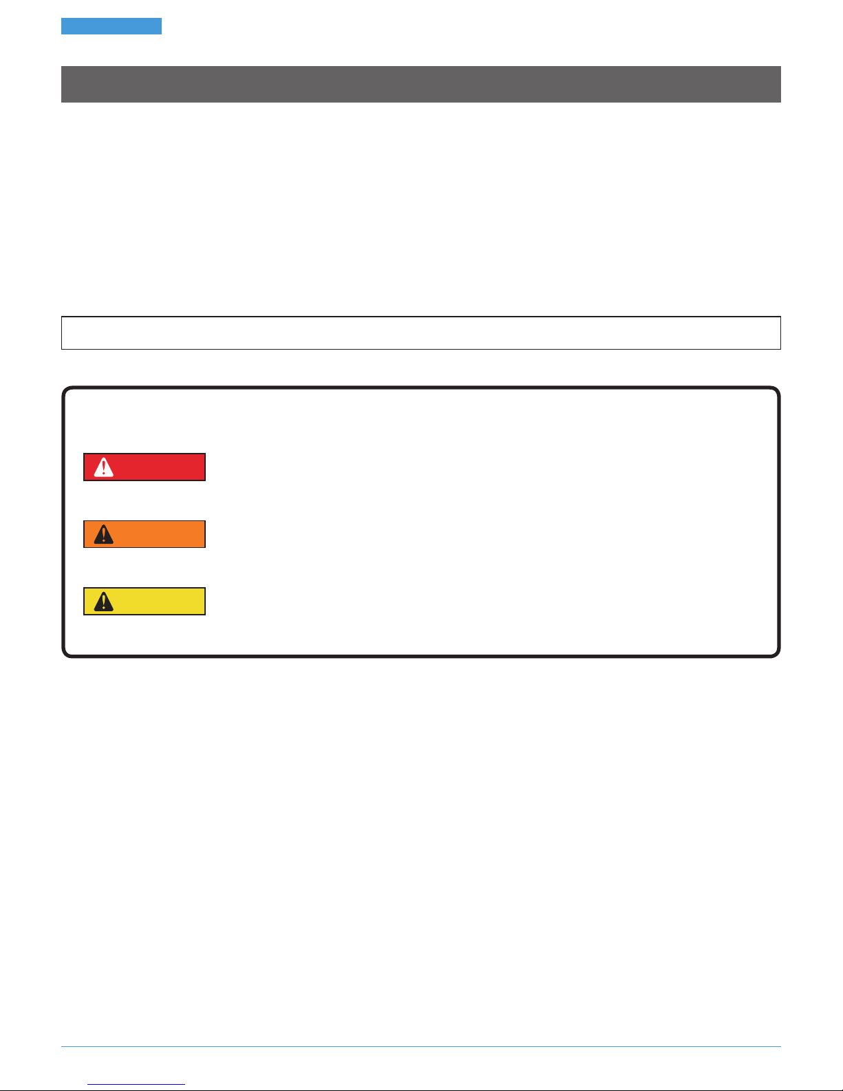
DANGER
Failure to follow the instructions will result in death or serious injury.
WARNING
Failure to follow the instructions could result in death or serious injury.
CAUTION
Failure to follow the instructions could cause personal injury or physical damage to equipment and surroundings.
4
TO ENSURE SAFETY
TO ENSURE SAFETY
WARNING
•
When installing components, be sure to follow the instructions that are given in the instruction manuals.
It is recommended that you use only genuine Shimano parts. If parts such as bolts and nuts become loose or damaged, the bicycle may suddenly fall
over, which may cause serious injury.
In addition, if adjustments are not carried out correctly, problems may occur, and the bicycle may suddenly fall over, which may cause serious injury.
•
Be sure to wear safety glasses or goggles to protect your eyes while performing maintenance tasks such as replacing parts.
•
After reading the dealer's manual thoroughly, keep it in a safe place for later reference.
Be sure to also inform users of the following:
•
Check that the wheels are fastened securely before riding the bicycle. If the wheels are loose in any way, they may come off the bicycle and serious
injury may result.
Brake
•
Each bicycle may handle slightly differently depending on the model. Therefore, be sure to learn the proper braking technique (including brake lever
pressure and bicycle control characteristics) and operation of your bicycle. Improper use of your bicycle's brake system may result in a loss of control or
a fall, which could lead to severe injury. For proper operation, consult a professional bicycle dealer or the bicycle's owner's manual. It is also important
to practice riding and braking, etc.
•
If the front brake is applied too strongly, the wheel may lock and the bicycle may fall forward, and serious injury may result.
•
Always make sure that the front and rear brakes are working correctly before riding the bicycle.
•
The required braking distance will be longer during wet weather. Reduce your speed and apply the brakes early and gently.
•
If the road surface is wet, the tires will skid more easily. If the tires skid, you may fall off the bicycle; therefore, to avoid this, reduce your speed and
apply the brakes early and gently.
Disc brake
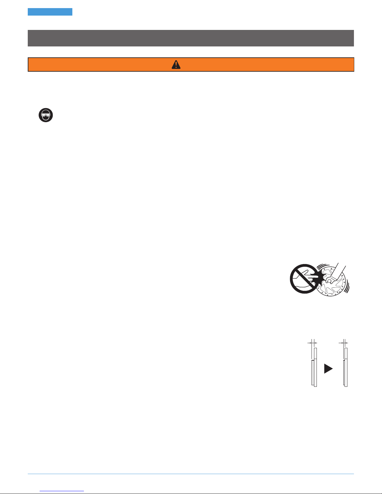
•
Please make sure to keep your fingers away from the rotating disc brake rotor. The disc brake rotor is sharp enough
to inflict severe injury to your fingers if caught in the openings of the disc brake rotor while it is moving.
•
The calipers and disc brake rotor will become hot when the brakes are operated; do not touch them while riding or immediately after dismounting
from the bicycle. Otherwise you may get burned.
•
Be careful not to allow any oil or grease to get onto the disc brake rotor and brake pads. Otherwise the brakes may not work correctly.
•
If any oil or grease gets on the brake pads, consult a dealer or an agency. Otherwise the brakes may not work correctly.
•
If noise occurs during brake operation, the brake pads may have been worn down to the usable limit.
After checking that the temperature of the brake system has cooled down sufficiently, check that the thickness of
each pad is 0.5mm or more. Or, consult a dealer or an agency.
0.5mm2mm
•
If the disc brake rotor is cracked or deformed, immediately stop using the brakes and consult a dealer or an agency.
•
If the disc brake rotor becomes worn down to a thickness of 1.5mm or less, or if the aluminum surface appears, immediately stop using the brakes and
consult a dealer or an agency. The disc brake rotor may break, and you may fall off the bicycle.

5
TO ENSURE SAFETY
For Installation to the Bicycle, and Maintenance:
•
When installing the hub to the frame, be sure to install the correct non-turn washers to the left and right sides, and securely tighten the hub nuts to
the specified torques. If the non-turn washers are installed to one side only, or if the hub nuts are not tightened sufficiently, the non-turn washer may
fall out, which could cause the hub axle to rotate and the cassette joint to turn.This may then cause the handlebars to be accidentally pulled by the
shifting cable, and an extremely serious accident could result.
•
Assemble the wheel with 3x or 4x spoke lacing. Do not spoke the wheel radially.
Otherwise, the spokes or the wheel may get damaged, or noise may occur when braking.
< CT-S500 / CT-S510 >
•
Use neutral detergent to clean the chain. Do not use alkali-based or acidbased detergents such as rust cleaners, as they may result in damage and/or
failure of the chain.
•
Use the reinforced connecting pin only for connecting the narrow type of chain.
•
If connecting pins other than reinforced connecting pins are used, or if a reinforced connecting pin or tool which is not suitable for that type of chain
is used, sufficient connection force may not be obtained, which could cause the chain to break or fall off.
•
If it is necessary to adjust the length of the chain due to a change in the number of sprocket teeth, make the cut at some other place than the place
where the chain has been joined using a reinforced connecting pin or an end pin.
The chain will be damaged if it is cut at a place where it has been joined with a reinforced connecting pin or an end pin.
End pin
Link pin Reinforced connecting pin
•
Check that the tension of the chain is correct and that the chain is not damaged.
If the tension is too weak or the chain is damaged, the chain should be replaced. If this is not done, the chain may break and cause serious injury.

6
TO ENSURE SAFETY
CAUTION
Be sure to also inform users of the following:
•
Shift the shifting lever one or two gears at a time. During shifting, reduce the force being applied to the pedals. If you try to force operation of the
shifting lever or shift three or more gears while the pedals are being turned strongly, your feet may come off the pedals and the bicycle may fall over,
which could result in serious injury.
Operating the shifting lever to multi-shift to a light gear may also cause the outer casing to spring out of the shifting lever. This does not affect the
capabilities of the shifting lever because the outer casing returns to the original position after shifting.
Disc brake
•
Disc brakes have a burn-in period, and braking force will gradually increase as the burn-in period progresses; therefore, make sure that you are aware
of any such increases in braking force when using the brakes during this period. The same thing will happen when the brake pads or disc brake rotor
are replaced.
NOTE
Be sure to also inform users of the following:
•
You can shift gears while lightly pedaling, but on rare occasions the pawls and ratchet inside the hub may produce some noise afterwards as part of
normal gear shifting operation.
•
The internal hub is not completely waterproof. Avoid using the hub in places where water might get inside it and do not use high-pressure water to
clean the hub, otherwise the internal mechanism may rust.
•
Do not disassemble the hub. If you need to disassemble it, consult the dealer where you made a purchase.
•
The internal geared hub has a built-in mechanism to support shifting, and when this support mechanism operates during shifting, noise or vibration
may occur. Depending on gear position, gear-shifting may feel different.
Noise may also occur if the gear is positioned at 5 to 8 (internal 8-speed hub) or 7 to 11 (internal 11-speed hub), when the crank is turned backward or
when the bicycle is pushed backward.
All of these phenomena occur due to the built-in gear-shifting structure and are not the failure of the internal components.
•
Products are not guaranteed against natural wear and deterioration from normal use and aging.
•
For maximum performance we highly recommend Shimano lubricants and maintenance products.

7
TO ENSURE SAFETY
For Installation to the Bicycle, and Maintenance:
•
The cassette joint should only be used with sprockets from 16T to 23T.
•
It is recommended that the chain ring of the front be set to the following gear ratio.
Sprocket
ratio
Front Rear
Model No. Gear
SM-GEAR FC-S5011 FC-S500
14 15 16 17 18 19 20 21 22 23 18 20 18 20
11-speed 1.8 - 2.0
FC-S5011
FC-C6000
38T - - - - - X X X - - - X - -
39T - - - - - - X X - - - X - -
42T - - - - - - - X X X - - - -
45T - - - - - - - - - X - - - -
8-speed 2.0 - 2.25
FC-S501
FC-S400
45T - - - - - - X X X - - - - X
42T - - - - - X X X - - - - - X
39T - - - - X X - - - - - - X -
•
In order to maintain proper performance, it is recommended that you contact the place of purchase or a bicycle dealer to carry out maintenance such
as internal oil replacement or lubrication after riding 1,000km from the start of use and then after about once every two years (or once about every
5,000km if the bicycle is used very frequently).
Also, it is recommended to use Shimano internal geared hub grease or a lubrication kit for the maintenance. If Shimano grease or a Shimano
lubrication kit is not used, problems such as a malfunction in gear shifting may occur.
•
If the wheel becomes stiff and difficult to turn, you should lubricate it with grease.
•
You should periodically wash the sprockets in a neutral detergent and then lubricate them again. In addition, cleaning the chain with neutral
detergent and lubricating it can be an effective way of extending the useful life of the sprockets and the chain.

8
TO ENSURE SAFETY
•
If the chain keeps coming off the sprockets during use, replace the sprockets and the chain.
•
If using a chain tensioner, use the special CS-S500 18T or 20T sprocket with chain guard. Do not use any other types of sprockets, otherwise the chain
may come off the sprockets.
< SG-S7001-11 >
•
When you perform oil maintenance, use the SG-S700 OIL or TL-S703 maintenance kit.
When you replace the oil, follow the manual for TL-S703. When you replace the seal on the right side, use TL-S704.
If SG-S700 OIL is not used, problems such as an oil leakage and gear shifting malfunction may occur.
< CT-S500 / CT-S510 >
•
Clean the chain tensioner periodically and lubricate all moving parts and pulleys.
•
If there is a large amount of play in the pulleys and an abnormal amount of noise is generated while riding, replace the pulleys.
•
Do not disassemble the pulley unit.
•
If the tension applied is too strong, noise may be generated while riding.
•
If the chain becomes elongated and excessive looseness occurs, readjust the chain tension.
< CT-S510 >
Applicable hubs Applicable sprockets Applicable fork end width Applicable fork end shape
Internal 7-speed / 8-speed 16 - 23T 4 - 9 mm Vertical
•
This product is for single front chainwheels only.
The actual product may differ from the illustration because this manual is intended chiefly to explain the procedures for using
the product.

LIST OF TOOLS TO BE USED

10
LIST OF TOOLS TO BE USED
LIST OF TOOLS TO BE USED
The following tools are required to assemble the product.
Tool Tool Tool
3mm hexagon wrench 15mm spanner TL-S700-B
4mm hexagon wrench Adjustable wrench TL-LR10
10mm spanner Screwdriver

INSTALLATION
12
INSTALLATION
Installation of the CS-S500 sprocket with chain guard
INSTALLATION
Installation of the CS-S500 sprocket with chain guard
1
(z)
(B)
(C) (D)
(A)
Install the chain guard to the right hand
dust cap of the hub body, and then
install right hand dust cap B to the
driver.
Install the right-hand dust cap B in the
orientation (z).
(A)
Right hand dust cap B
(B)
Chain guard
(C)
Right hand dust cap
(D)
Driver
2
(B)
(C) (A)
(D)
Install the CS-S500 sprocket to the driver
on the right side of the hub body with
the guard plate facing outward, and
secure it in place with the snap ring.
(A)
Driver
(B)
Snap ring
(C)
Guard plate
(D)
CS-S500 Sprocket
13
To be continued on next page
INSTALLATION
Installation of the cassette joint to the hub
Installation of the cassette joint to the hub
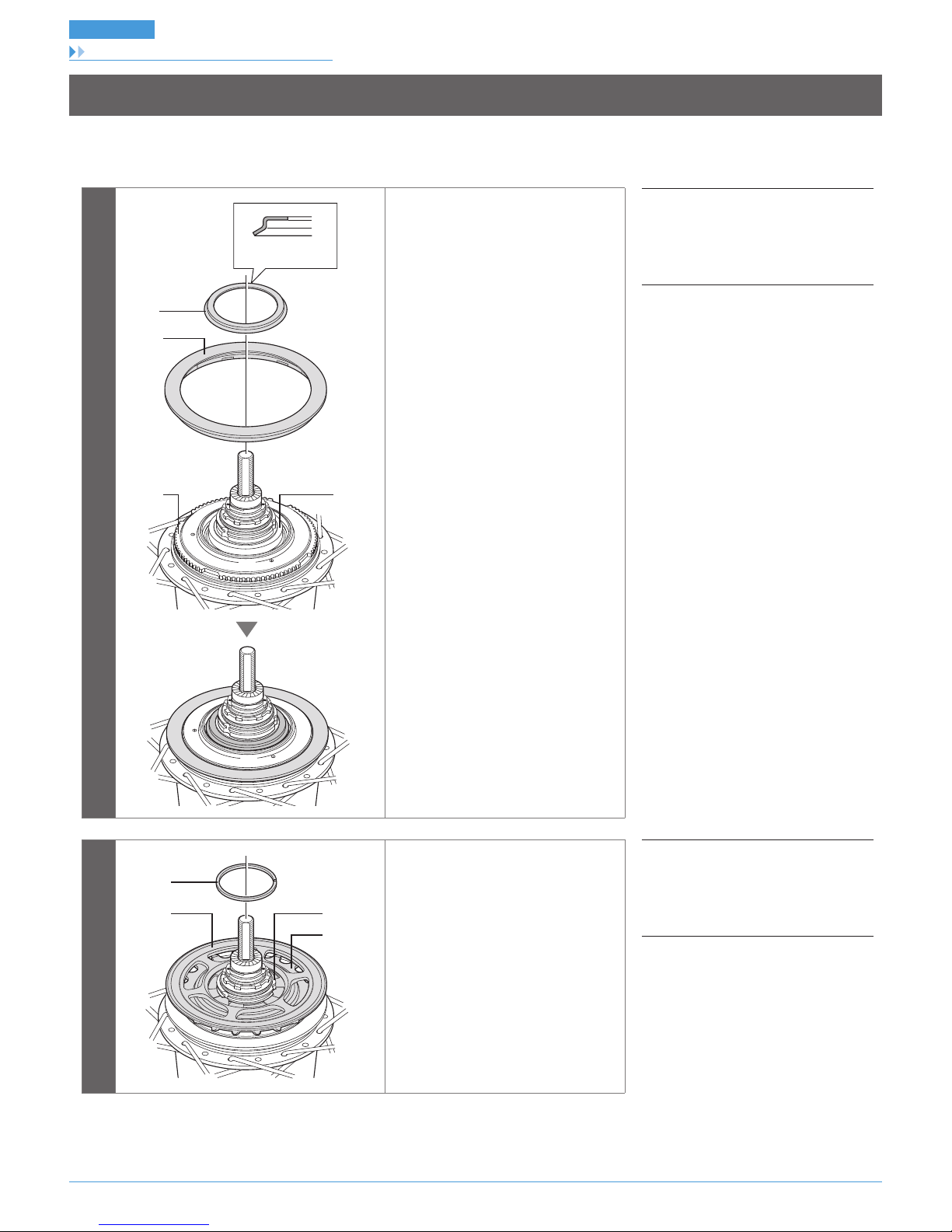
1
(z)
(A)
(B)
Install the driver cap to the driver on the
right side of the hub body.
Install the driver cap in the orientation
(z).
(A)
Driver cap
(B)
Driver
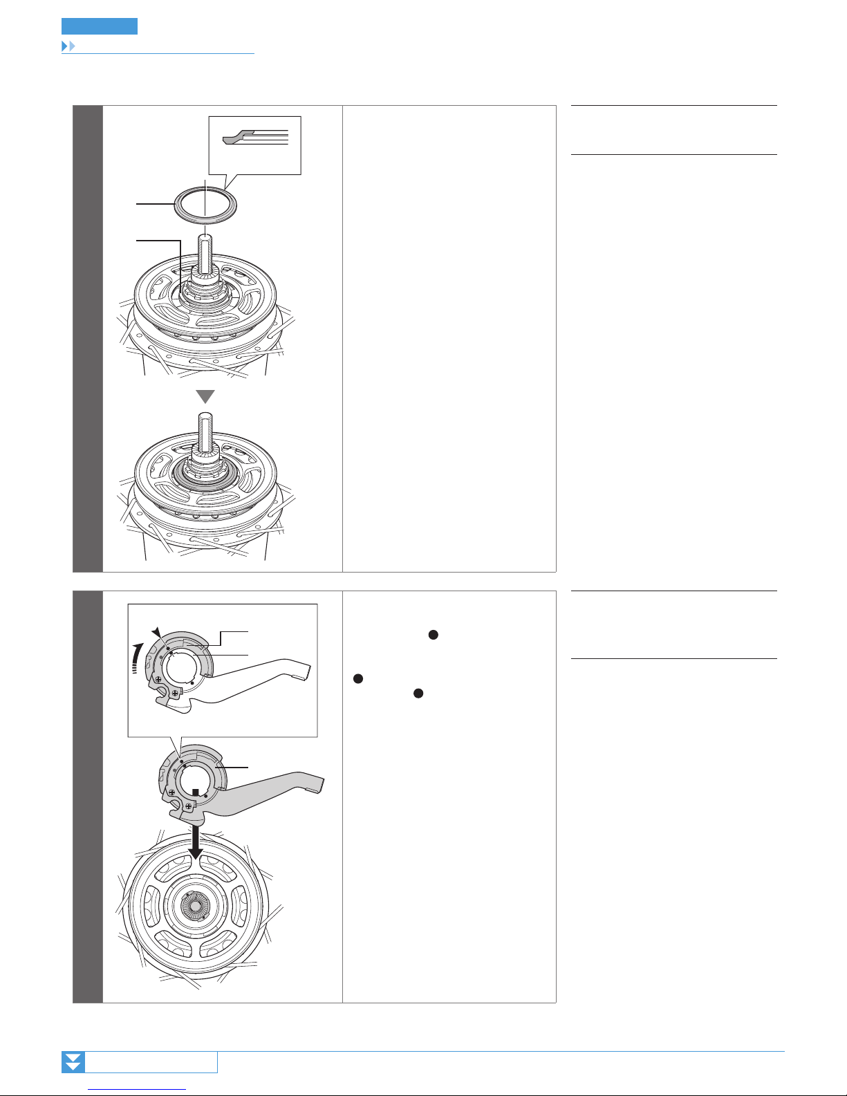
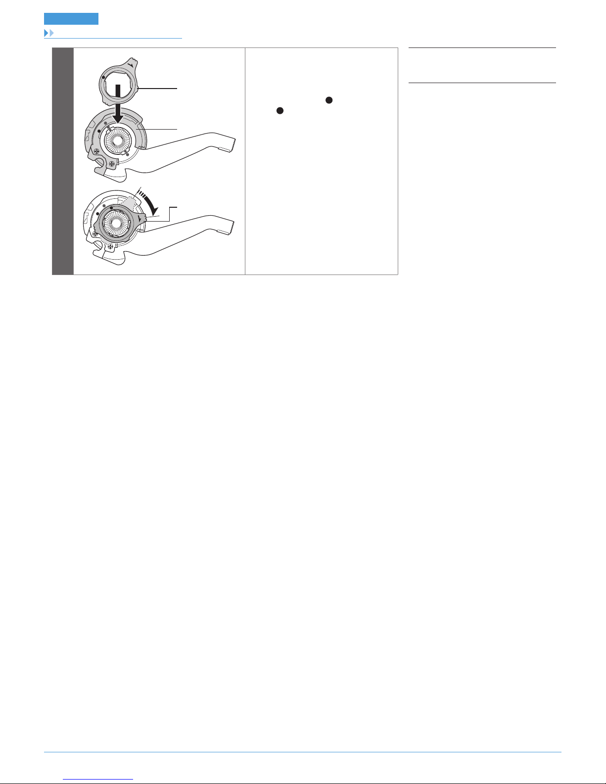
2
(A)
(B)
(C)
Turn the cassette joint pulley in the
direction of the arrow in the illustration
to align the red marks on the pulley
and the bracket.With the cassette joint
in this condition, install it so that the red
mark on the cassette joint is aligned
with the red mark on the right side of
the hub body.
(A)
Pulley
(B)
Bracket
(C)
Cassette joint
14
INSTALLATION
Installation of the cassette joint to the hub
3
LOCK
LOCK
(B)
(A)
(B)
Secure the cassette joint to the hub with
the cassette joint fixing ring.
When installing the cassette joint fixing
ring, align the yellow mark with the
yellow mark on the cassette joint
pulley, and then turn the cassette joint
fixing ring 45° clockwise.
(A)
Pulley
(B)
Cassette joint fixing ring
15
INSTALLATION
Installation of the disc brake rotor
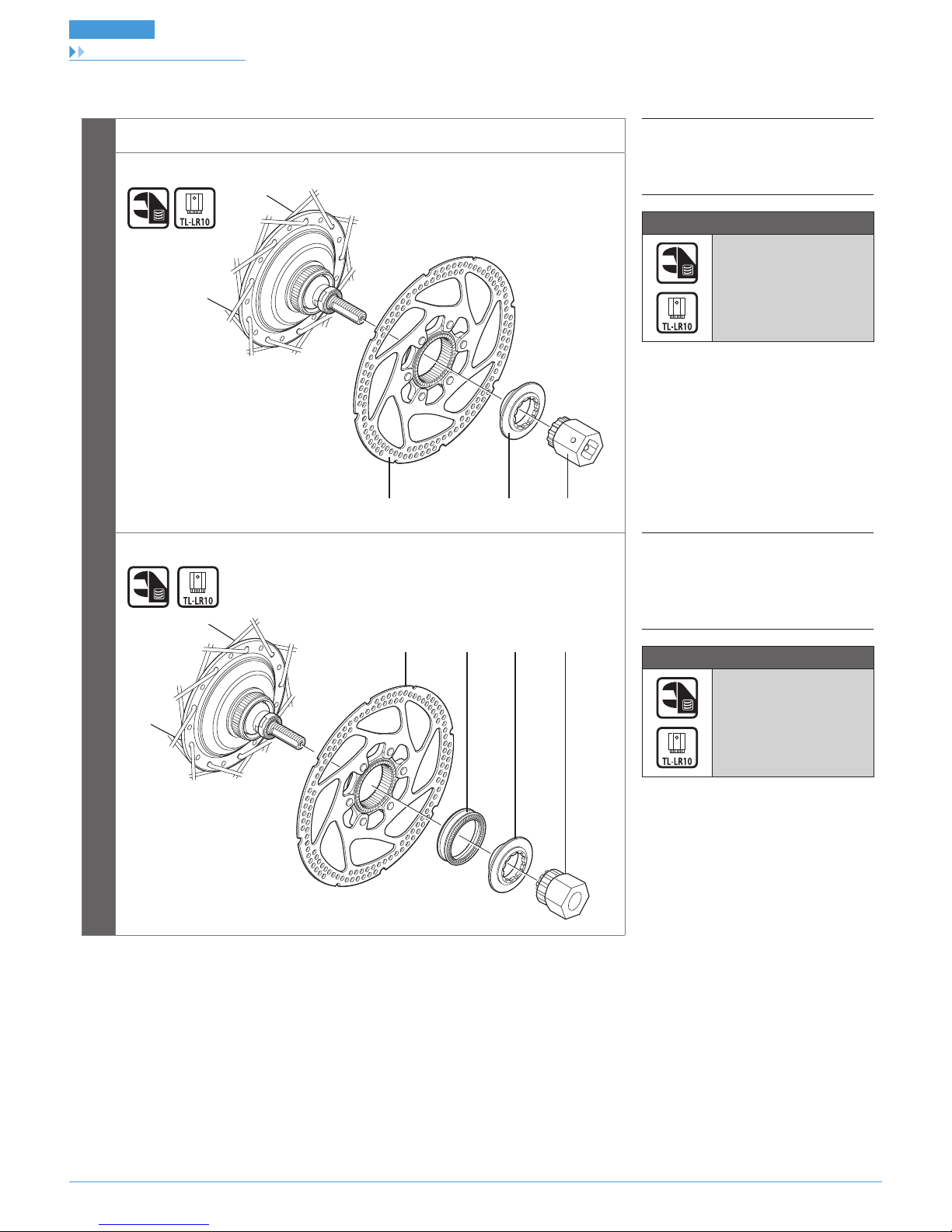
Installation of the disc brake rotor
Install the disc brake rotor as shown in the illustration.
(A)
Disc brake rotor
(B)
Disc brake rotor installation ring
(C)
TL-LR10
Tightening torque
40 N·m
SG-S7001-8
(A) (B) (C)
SG-S7001-11
(A) (B) (C) (D)
(A)
Disc brake rotor
(B)
Rotor spacer
(C)
Disc brake rotor installation ring
(D)
TL-LR10
Tightening torque
40 N·m
 Loading...