

Page 1

1. Features of the SC-7900
••••••••••••••••••••••••
6
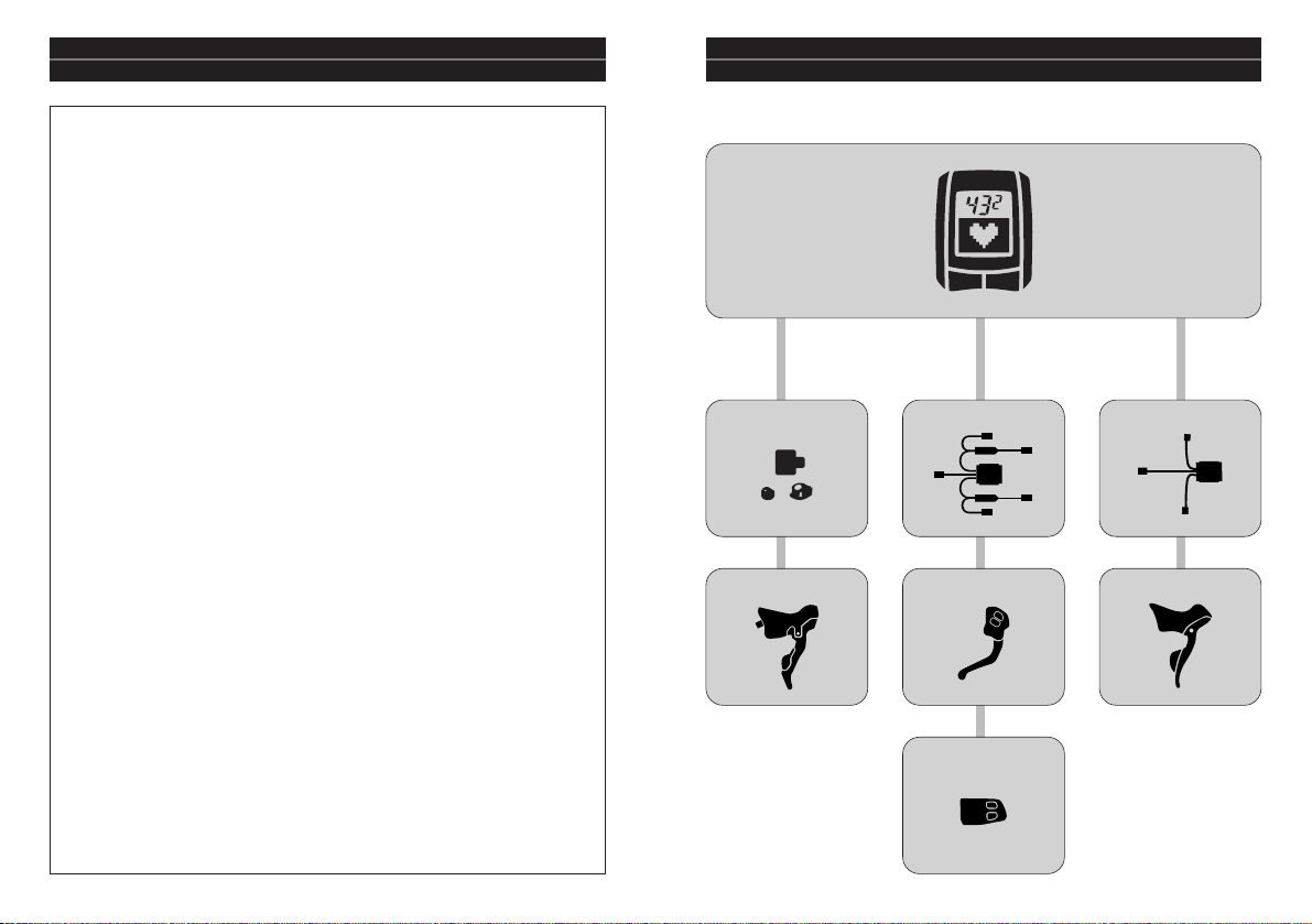
2. Table of Optional Item Combinations
••••••••••••••
7
• Bracket combinations
•••••••••••••••••••••••••••
7
3. Product Overview
•••••••••••••••••••••••••••••
8
• Package contents
••••••••••••••••••••••••••••••
8
• Options
•••••••••••••••••••••••••••••••••••••
9
4. Replacing the Batteries
•••••••••••••••••••••••••
11
5. Pairing Function
•••••••••••••••••••••••••••••••
13
6. Installation
•••••••••••••••••••••••••••••••••••
14
7. Basic Operation
•••••••••••••••••••••••••••••••
19
• Power supply (ON)
•••••••••••••••••••••••••••••
19
• Sleep mode (power saving function)
•••••••••••••••••
19
• Restarting in initialization mode
•••••••••••••••••••
20
• Restarting from sleep mode
•••••••••••••••••••••••
22
• Backlight illumination
•••••••••••••••••••••••••••
22
8. Display Functions
•••••••••••••••••••••••••••••
23
• LCD display details
•••••••••••••••••••••••••••••
23
• Low battery / low memory indicator
•••••••••••••••••
23
• Normal mode details
•••••••••••••••••••••••••••
25
9. Setting Modes
••••••••••••••••••••••••••••••••
26
• Main menu
••••••••••••••••••••••••••••••••••
27
• SETTING mode
••••••••••••••••••••••••••••••••
28
Bike settings
••••••••••••••••••••••••••••••••
28
System settings
••••••••••••••••••••••••••••••
30
User settings
••••••••••••••••••••••••••••••••
32
Setting your heart rate zone
•••••••••••••••••••••
35
Setting the altitude
•••••••••••••••••••••••••••
36
Checking the pairing
••••••••••••••••••••••••••
37
• FILE VIEW mode
•••••••••••••••••••••••••••••••
37
Viewing files
••••••••••••••••••••••••••••••••
37
Deleting files
•••••••••••••••••••••••••••••••
39
Cycle Computer SC-7900
English
3–52
Dutch
53–100
German
101–148
French
149–196
Spanish
197–244
Italian
245–292
Japanese
293–340
English
INDEX
3
Page 2
5
• Be careful not to pay excessive attention to the main unit LCD
while riding, otherwise you may have an accident.
• Do not use this product if you are using a heart pacemaker.
• This product is not a medical device. Data values should be used as
references only.
• Button batteries which have been removed after use should be
kept in a safe place out of the reach of children to avoid accidental
swallowing.
• If batteries are swallowed by mistake, seek medical advice
immediately.
• Do not use any batteries other than those specified. If the batteries
explode or leak, fire, personal injury or damage to surrounding
objects may occur.
• Used batteries should be disposed of in accordance with local
waste regulations.
Note:
* Equipment such as high-voltage power lines, signal devices, trams,
personal computers and LED lights may affect the cycle computer and
cause the heart rate to display incorrectly.
* Handle each unit carefully, and avoid subjecting them to any shocks.
* Avoid leaving the units exposed to extremely hot weather conditions for
long periods.
* The units are designed to be fully waterproofed to withstand wet
weather riding conditions; however, do not deliberately place them into
water.
* Never disassemble any of the SC-7900 components, as they cannot be
reassembled.
* The all clear (AC) switch is used to clear the date and time information.
* Do not use thinner or other solvents to clean any of the components.
Solvents may damage the main unit and sensor surfaces.
* To clean these parts, wipe them with a cloth soaked in a weak mixture of
neutral detergent and water.
* Natural wear and deterioration which occurs as a result of normal use is
not covered by warranty.
* If the button batteries are used incorrectly, they may leak or explode, so
make sure you observe the following points.
· Use only the specified batteries. Other types of battery cannot be used.
· Remove the batteries if they are not going to be used for long periods.
· If the batteries can no longer be used, they should be removed
immediately.
· Do not recharge the batteries.
· Insert the batteries so that the + and – sides are correctly aligned.
· Never throw the batteries into fire.
* None of the parts of the SC-7900 are interchangeable with the previous
FLIGHT DECK system, and cannot be used in conjunction with them.
* All units are connected wirelessly, and therefore there may be a slight
amount of time lag before displays appear.
Safety precautions
WARNING
10. Stopwatch Function / Recording Traveling Data
••••
40
11. FLIGHT DECK Manager
••••••••••••••••••••••••
43
FLIGHT DECK Manager functions
••••••••••••••••••
43
System requirements for using the software
••••••••••
44
Installing FLIGHT DECK Manager
••••••••••••••••••
45
Launching for the first time
•••••••••••••••••••••
46
Installing the driver for the USB dongle
•••••••••••••
47
Connecting to the main unit (PC-LINK)
••••••••••••••
48
12. Updating the Software
••••••••••••••••••••••••
49
13. Troubleshooting
•••••••••••••••••••••••••••••
49
14. Main Specifications/Display Ranges
••••••••••••••
50
4
Page 3
6 7
1. Features of the SC-7900 2. Table of Optional Item Combinations
Display can switch to show a variety of traveling data.
(Page 25)
Traveling data such as distance, time, heart rate condition, calorie
consumption, altitude and slope are displayed in the LCD of the main
unit.
Automated stopwatch counter (Page 40)
The stopwatch counter can be started and stopped automatically by
detecting the bicycle speed.
Remote operation from ST/SW (Page 25, 42)
Changing the display and recording lap data can be carried out by
remote using the dual control lever or the shifting switch.
Units are paired and connected wirelessly (Page 13, 21, 22)
The speed sensor, heart rate sensor and ST wireless units (optional)
are connected wirelessly. Up to a maximum of four bicycles can be
registered in a single main unit. The main unit can be shared between
the registered bicycles, and you can change which registered bicycle
you ride.
Managing your heart rate (Page 35, 36)
You can specify the minimum heart rate and maximum heart rate to
use as targets for indicating your level of activity. If your heart rate
goes outside the set limits, the main unit can notify you by means of
a buzzer and the heart rate value flashing on the display.
Checking the display in dark places (Page 22)
Backlight illumination lets you check the information appearing on
the LCD even in dark places.
Managing data using a computer (Page 43)
Communication between a personal computer and the main unit is
possible by means of a USB dongle (optional).
This can be used to retrieve traveling data from the main unit, display
this data in the form of graphs, change main unit settings and update
the main unit software.
Bracket combinations
SM-EW79F-E
ST-7970
SC-7900
SM-EW79F-I
For ST-7971
(Time Trials/Triathlon)
For ST-7900/6700 For ST-7970
ST-7971
SW-7971
SM-SC79
ST-7900/6700
Page 4
98
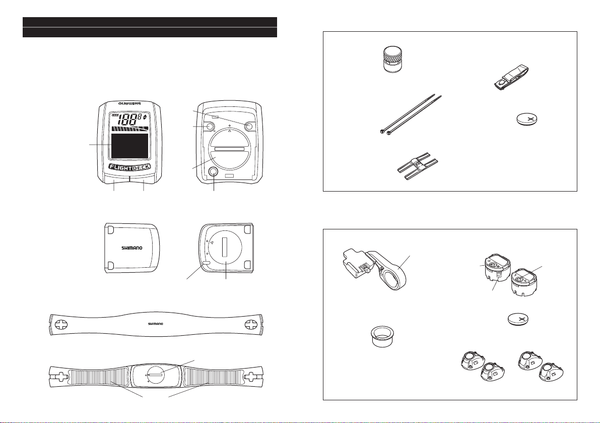
3. Product Overview
Package contents
Accessories
Check that all of the following products are present.
REC
AT
rpm
Km/h
Mile/h
■
Main unit
(cycle computer)
SC-7900
• Magnet
• Bracket • ST wireless units
(1 each for left and right)
• Top cover for ST wireless unit
Options
■
Bracket set for FLIGHT DECK SM-SC79 (for ST-7900/6700)
• Cable ties for
securing speed
sensor (x4)
• Rubber seat for
speed sensor
• Rubber belt for heart rate
sensor unit
• Battery
• Service Instructions
(This booklet)
• Application CD-ROM
• Bracket band adapter
For 25.8 mm inner diameter
■
Speed sensor
■
Heart rate sensor unit
SM-HR79
(Front) (Rear)
(Front)
(Front)
(Rear)
Electrode
Battery cap
Battery capSensor marker
Bracket band
Mode button
(right)
Battery eject slit
Lap
button
(left)
CR2450 (x1)
CR2032 (x1)
CR1632 (x1)
• Battery
CR1632 (x2)
Battery
cap
Button B
Set button
(Stopwatch button)
All clear (AC) switchSelect button
LCD
(Rear)
(for ST-7900)ST(for ST-6700)
Button A
• Bracket fixing screws
18mm (x1)
15mm (x1)
Page 5

■
Main unit
Battery used: CR2450 (x1)
10 11
■
Bracket set for FLIGHT DECK
SM-EW79F-E (for ST-7970)
Bracket band
Rear derailleur
adjustment button
• Bracket
■
USB dongle SM-DL79
USB port cover
• Bracket band adapter
For 25.8 mm inner diameter
■
Bracket set for FLIGHT DECK
SM-EW79F-I (for ST-7971/SW-7971)
• Bracket
• Bracket fixing screws
18mm (x1)
15mm (x1)
12mm (x1)
• Bracket band
• Bracket band adapter
For 25.8 mm inner diameter
4. Replacing the Batteries
Insert so that the + side is facing upward as shown in the illustration, and
then close the battery cap.
CAUTION:
• Always be sure to operate the buttons to force
the main unit into sleep mode before replacing
the main unit battery.
• If you replace the battery without setting the
main unit to sleep mode first, the main unit will
start up in initialization mode.
* For details on initialization mode,
refer to page 20.
• When replacing the battery of the main unit, remove the old battery
and then wait at least 10 seconds before inserting the new battery.
• If the low battery indicator appears in the main unit display, replace
the battery with a new one straight away.
• If carrying out pairing between the main unit and the other units,
batteries must be inserted into the other units too.
* Refer to page 13 for details on pairing.
■
Speed sensor
Battery used: CR1632 (x1)
CAUTION:
If the speed is not being displayed correctly in the
main unit display, repeat the pairing operation. If
this still does not solve the problem, replace the
speed sensor battery with a new one.
Open
Close
Open
Close
Adapter
Rear derailleur
adjustment button
• Bracket fixing screws
18mm (x1)
15mm (x1)
• Aero bar protective sticker
• Cable ties for securing
adapter (2 types x4)
The batteries for units other than the main unit should be inserted
when the units are being paired.
In order to increase the operating life of the battery, it is
recommended that you set the main unit to sleep mode after use so
that it consumes less power. (For details on sleep mode, refer to
page 19.)
Page 6

(1) Press button A and button B on the main unit simultaneously to start
up setting mode.
(For details on starting up setting mode, refer
to page 26.)
(2) Select “SETTING” in the main menu. Then
select “PAIRING” in the Setting menu so that
the pairing confirmation screen is displayed.
If pairing has not yet been carried out for a
particular unit, “–“ will appear beside the
name of the unit. If pairing has already been carried out for a unit,
“™” will appear.
1312
■
ST wireless units
Battery used: CR1632 (x1)
(1) Insert so that the - side is facing upward as
shown in the illustration.
(2) Close the battery cap so that it is back in its
original position.
* To remove the battery, insert a thin object into the
battery eject slit and push out the battery, while
being careful not to damage the battery or the unit.
• Button batteries which have been removed after use should be kept
in a safe place out of the reach of children to avoid accidental
swallowing.
• If batteries are swallowed by mistake, seek medical advice
immediately.
• Do not use any batteries other than those specified. If the batteries
explode or leak, fire, personal injury or damage to surrounding
objects may occur.
• Used batteries should be disposed of in accordance with local waste
regulations.
WARNING
■
Pairing setting method
5. Pairing Function
In order for the main unit to display information from each of the sensors,
the various units must first be registered with the SC-7900 system.
This is called ‘pairing’.
(3) Press the select button on the main unit to switch to pairing standby
mode.
While the main unit is in pairing standby mode,
insert the batteries into the units which you
would like to carry out pairing for.
* The units will switch to pairing mode for 30
seconds after their batteries are inserted.
* The SM-EW79F-E/I will switch to pairing mode
for 30 seconds once the battery for the gear
shifting system has been connected.
(4) Press the select button and the set button on
the main unit simultaneously within the 30
seconds that the unit to be paired is in pairing
mode.
“SCANNING” will appear in the data display
and pairing will then start.
The heart rate sensor unit will operate and battery
power will be consumed if the electrodes are
touched, even if it is not fitted to your body.
In order to avoid battery power being consumed
unnecessarily, remove the heart rate sensor unit and
set the main unit to sleep mode immediately after
use.
■
Heart rate sensor unit
Battery used: CR2032 (x1)
Open
Close
(–)
(+)
Page 7

(1) Determine the installation
position for the bracket,
and then attach the aero
bar protective sticker.
(2) Install the bracket to the
handlebar as shown in the
illustration. Tighten the cable tie along the groove in the adapter.
Tighten the cable tie along the groove in the adapter.
1514
(6) Repeat steps (3) and (4) for each unit until all units have been paired.
(7) Once pairing has been completed for all units, press the set button
(exit▼) to exit the pairing operation.
* If multiple SC-7900 users carry out pairing simultaneously, the units
for other users may become paired with your own system.
In order to make sure that pairing is carried out correctly, do not
carry out pairing near any other users who are also carrying out
pairing, or near any other devices which may operate wirelessly.
* After pairing has been completed, each user should check to make
sure that pairing has been carried out correctly.
* The st-R and st-L (ST wireless units) are optional.
* The ST wireless units will start operating once bot the left and right
units have finished being paired. They will not operate only by
themselves.
(SM-EW79F-E/I) (SM-SC79)
(5) When pairing is complete, “™”wil appear beside the name of the unit
which has just been paired. If you press the
select button, the main unit will switch to
pairing standby mode. You can then continue
to carry out pairing operations for any other
unit which has not yet been paired.
* Do not press the set button (exit▼) until
pairing has been completed for all units.
< SM-SC79, SM-EW79F-E/I >
(1) Install the bracket band to the middle of the
bicycle handlebars. Tighten the band using the
fixing bolt.
Handlebar installation diameter :
31.8 mm / 25.8 mm (using an adapter)
Tightening torque : 1.5 N·m {13 in.lbs}
(2) Install the bracket to the band.
Tightening torque = 1.0 N·m {8 in.lbs}
■
Installing the bracket
■
Installing the bracket to the aero bar
6. Installation
CAUTION:
Carry out pairing for a unit before installing the unit.
(For details on pairing, refer to page 13.)
< SM-EW79F-I >
(1) Before installing the main unit, switch it to setting mode and set the
user details and any other necessary settings.
(For details on starting up setting mode and methods of operation,
refer to page 26.)
(2) Slide the main unit into the bracket
as shown in the illustration to install
it. At this time, insert the main unit
securely until it clicks into place.
■
Installing the main unit
Aero bar protective sticker
* For the SM-EW79F-I, replace the adapter and
band to match the handlebars being used if
required.
Tightening torque = 1.0 N·m {8 in.lbs}
(For details on connecting the cables, refer to page 00.)
Adapter 12 mm
18 mm
15 mm
Page 8

■
Heart rate sensor unit
1716
(1) Use a screwdriver to secure the
accessory magnet (x1) to the right side
of the front wheel as shown in the
illustration.
(2) Use two of the accessory cable ties to
provisionally secure the speed sensor to
the front fork as shown in the
illustration.
■
Installing the speed sensor
(1) Attach the hook of the rubber belt onto the
plastic part (electrode). Attach the belt directly
to your body so that the plastic part is close
against your skin.
(2) The signal will be sent from the casing to the
main unit via a transmitter, so attach the belt
to the middle of your stomach area as shown in
the illustration.
• In order to eliminate measurement errors, it is recommended that
you moisten the electrode with water before attaching the belt.
• Dry skin or thick body hair may affect the reliability of measurement.
• If the weather is cold or your skin is dry, measurement errors may still
occur even if the sensor is fitted directly against your skin.
(3) Adjust the positions of the speed sensor and magnet so
that the magnet passes directly over the marker of the
speed sensor.
• Distance between speed sensor and magnet: 1 - 5 mm
• Distance between main unit and speed sensor
Horizontal: 10 cm or less
123
Vertical: 50 cm or less
(4) Once the installation positions have been
decided upon, securely tighten the speed
sensor and the magnet.
(1) Open up the bracket cover and remove the top
cover of the lever unit.
(2) Check whether the wireless unit is for the left or right, and then insert
it so that the markings are aligned correctly.
■
Installing the ST wireless units
(For the SM-SC79)
Page 9

1918
(3) Install the ST wireless unit as shown in the illustration,
and then fit the top cover and secure it by tightening
the screw.
Tightening torque = 0.13 - 0.15 N·m {1.1 - 1.3 in.lbs}
* The shape of the top cover to be installed is different
for the ST-7900 and the ST-6700.
7. Basic Operation
Power supply (ON)
The power supply for each component is supplied by the following
operations and actions.
■
Main unit
The power supply for the main unit turns on when any one of the set
button, select button, button A or button B is pressed.
■
Speed sensor
The power supply for the speed sensor turns on when the magnet
passes over the speed sensor.
■
Heart rate sensor unit
The power supply for the heart rate sensor unit turns on when the
sensor unit detects that the electrode has been placed against your
body.
■
ST wireless units
The power supply for the ST wireless units turns on when you press both
the mode button and the lap button on the ST wireless units.
* The power does not turn on when a gear shifting operation occurs.
Sleep mode
(power saving function)
The power supply for each component switches to sleep mode by the
following operations and actions.
■
Main unit
The main unit switches to sleep mode if no
buttons on the main unit or on the ST wireless
units have been pressed for over 30 minutes, or
if there have been no signals detected from the
speed sensor or heart rate sensor unit.
If you hold down the set button and the select
button simultaneously for 2 seconds or more, it
will force the main unit to switch to sleep mode.
(If the stopwatch is currently operating or if the main unit is in setting
mode, it will not switch to sleep mode.)
■
Connection of the electric cables
Cable connection diagram
R: Right L: Left
ST-7970(L)
White
(For the SM-EW79F-E) (For the SM-EW79F-I)
ST-7970(R)
Red
ST-7971(L)
White
ST-7971(R)
Red
SW-7971(L)
Yellow
SW-7971(R)
Green
To derailleur
To derailleur
Page 10

2120
■
ST wireless units
If there have been no button operations or gear shifting operations for
30 minutes or more, the ST wireless units will switch to sleep mode.
Restarting in initialization mode
If the language or the units have been changed, the main unit will start up
in initialization mode.
* The main unit will also start up in initialization mode when the power is
turned on for the first time.
■
Restarting in initialization mode
(1) Replace the main unit battery or press the all clear switch to reset the
main unit.
(2) Turn on the power supply for the main unit.
However, if the battery is replaced while the main unit has been in
sleep mode for less than 30 seconds, the main unit will not start up in
initialization mode.
(3) The startup screen for initialization mode will
be displayed (for 3 seconds).
(4) Press the select button, button A and button B
to select the display language.
(5) Press the set button to confirm the display
language selection.
(6) Press the select button, button A and button B
to select the units.
(7) Press the set button to confirm the units
selection.
(8) The startup screen will be displayed (for 3
seconds).
(9) The bike No. selection screen will be displayed
(for 3 seconds).
(10) If you press the select button while this screen
is displayed, the bike number will flash and
the bike number can then be changed. If you
press the select button once more, the bike
number can then be changed.
• Bike No.: 1-4
(11) Press the set button to confirm the bike
number selected.
(12) The remaining memory/remaining time
display will appear (for 3 seconds).
• User memory: 0% - 100%
(no remaining memory when 0%)
• Record time: Length of time that traveling
data can be recorded
CAUTION:
Check that there is enough memory
remaining before riding the bicycle.
(13) The normal mode screen will be displayed.
Page 11

2322
Restarting from sleep mode
(1) The startup screen will be displayed (for 3
seconds).
Backlight illumination
(1) Hold down the select button on the main unit (for 2 seconds or more).
(2) The backlight of the LCD will illuminate (for 3 seconds).
(6) The normal mode screen will be displayed.
(2) The bike No. selection screen will be displayed
(for 3 seconds).
(3) If you press the select button while this screen
is displayed, the bike number will flash and the
bike number can then be changed.
If you press the select button once more, the
bike number will increase.
• Bike No.: 1-4
(4) Press the set button to confirm the bike
number selected.
(5) The remaining memory/remaining time display
will appear (for 3 seconds).
• User memory: 0% - 100% (no remaining
memory when 0%)
• Record time: Length of time that traveling
data can be recorded
CAUTION:
Check that there is enough memory remaining
before riding the bicycle.
8. Display Functions
LCD display details
example shows the largest
chainring and the 6th sprocket.)
4. Information display
For details, refer to page 00.
5. Automatic mode display
Displayed when the stopwatch
mode is set to AUTO.
6. Memory operation display
Rec is displayed while traveling
data is being recorded.
7. Battery charge display
The battery charge for the gear
shifting system is displayed
when the bracket set (SMEW79F-E/I) is being used. (It is
not displayed when the SMSC79 is being used.)
(Display example)
1
2
6
5
3
4
7
<Low battery indicator>
When the battery level for any of the batteries in the units is at a low level, a
low battery confirmation screen is display by the main unit as a notification.
This display can be cleared by pressing the set button, select button, button A
or button B on the main unit.
■
Low battery/low memory indicator
1. Speed (km/h, mph)/
cadence display (rpm)
The cadence is displayed while
the speed is appearing in the
information display.
2. Pace arrow display
If the current traveling speed is
faster than the average speed,
an upward-pointing arrow will
be displayed, and if it is slower,
a downward-pointing arrow
will be displayed. (They are only
displayed while the stopwatch
counter is being displayed too.)
3. Gear indicator
This displays the gear being
used as an icon. (The display
Page 12

2524
Press button A or the mode button.
Press the select button, or hold
down the mode button (for 2
seconds or more).
Select button
Normal mode details
■
Display Mode 1
Button A
Mode button
Clock
(CLK)
Traveling distance
(DST)
Cumulative distance
(ODO)
Split display
(SPLT)
Lap display
(LAP)
■
Display Mode 2
Cadence
(CAD)
Speed
(VEL)
Maximum speed
(MAX)
Average speed
(AVE)
Calories
(CAL)
■
Heart rate mode
Calories
(CAL)
Average heart rate
(AVE)
Maximum heart
rate (MAX)
Zone transition
time (ZONE)
■
Altitude/slope mode
Altitude
(ALT)
Slope
(SLP)
Cumulative increased
altitude (CALT)
■
Battery/memory mode
Battery charge
display
Memory
remaining
For details on measurement of the traveling
time, refer to page 42.
If the low battery indicator is being displayed for a unit, replace the battery for
that unit as soon as possible.
* The respective units must be paired for this to happen.
Low battery icon
(Low battery
confirmation screen)
Main unit display Unit
sc Main unit
spd Speed sensor
hrm Heart rate sensor unit
st-R ST wireless unit /right (optional)
st-L ST wireless unit /left (optional)
Press a button on
the main unit
<Low memory indicator>
When the amount of spare memory for recording traveling data in the main
unit drops to 10% or less, the low memory confirmation screen is display by the
main unit as a notification. This display can be cleared by pressing the set
button, select button, button A or button B on the main unit.
If the low memory indicator appears, delete any unneeded traveling data to
make more free memory available.
(For details on how to delete data, refer to page 39.)
• If the low battery indicator and the low memory indicator are generated at
the same time, each screen will be displayed alternately for one second.
• If you clear the low battery indicator or low memory indicator while riding
the bicycle, the low battery or low memory confirmation screen will be
displayed once more when speed signals are no longer being input.
(Low memory
confirmation screen)
Press a button on
the main unit
• When using in combination with the bracket set (SM-EW79F-E/I), the low
battery indicator will not be displayed even when the battery level for the
gear shifting system is low.
• It is also not displayed during PC-LINK mode or while the pairing confirmation
screen is being displayed.
 Loading...