

Shimadzu UW420S, UW2200H, UW4200H, UW6200H, UW820S Instruction Manual
...
Electronic Balance
Instruction Manual
UW series
UX series
M054-E117D
Read These Pages Before Installation
READ AND UNDERSTAND THIS MANUAL BEFORE
OPERATION. SAVE THIS MANUAL.
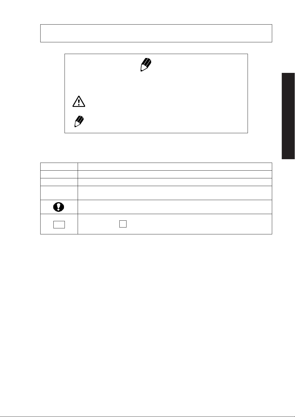
Notation Conventions
Note
This instruction manual uses the following notation conventions to indicate
Safety Precautions and additional information.
Caution
Note
Other conventions used in this manual include:
Item Description
1, 2, 3 .... Indicates the step number in a procedure or a sequence of changes in the balance display.
[ ] key Indicates the operation key on the balance. See 2.2.
mass display
No.
Indicates that the balance is in the weighing mode and mass is displayed in one of the weighing units.
These sections include information to make using the balance more convenient.
Indicates the menu item to be selected.
The number in the
See 7.2 “Menu Map”.
Indicates a potentially hazardous situation that may
result in injury to personnel or equipment damage.
Provides additional information needed to properly
use the balance.
is the number of the menu item on the Menu Map.
Read These Pages Before Installation
- I -
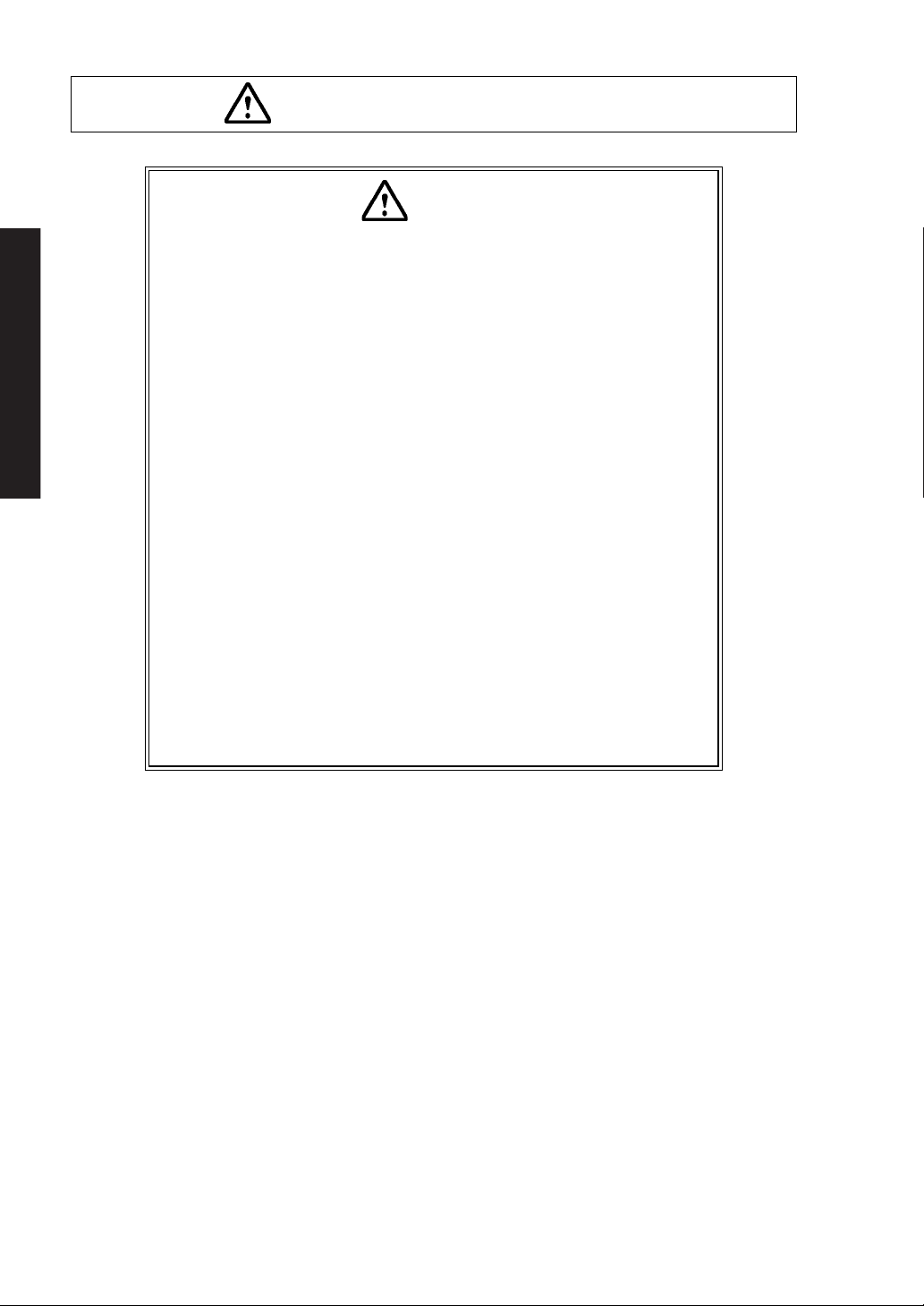
To ensure safe and proper operation of the balance, observe the following
precautions.
• Do not use the balance in hazardous areas.
This includes areas where the balance is expose to dust or flammable
gases and liquids.
• Use the AC adapter specified by Shimadzu.
To prevent electric shock, never disassemble the AC adapter.
The AC adapter is designed for indoor use. Do not use the AC adapter in
exterior environments or where it may be splashed by water.
Ensure that the power supply voltage meets the indicated range of the
Read These Pages Before Installation
AC adapter.
• Handle the balance carefully.
The balance is a precision instrument of solid design.
• Do not connect peripheral devices other than those recommended
by Shimadzu.
The balance may not operate properly if peripheral devices other than
those specified in this manual are used. The specifications of the RS-
232C/AUX connector are described in Appendix 4. Connect the periph-
eral devices according to the methods described in this instruction man-
ual.
• Do not disassemble the balance, accessories, or peripheral unit.
Safety Precautions
Caution
- II -

Declaration Of Conformity
Shimadzu Corporation declares that the following products:
UW Series and UX Series Electronic Balances
conform to the following directives.
Directives
EMC directive 89/336/EEC amended by 92/31/EEC, 93/68/EEC
EN55022: 1994 / A1: 1995 / A2: 1997 (Class B)
EN55024: 1998
EN61000-3-2: 1995 /A1: 1998 /A2: 1998, EN61000-3-3: 1995
Low Voltage directive 73/23/EEC amended by 93/68/EEC
EN60950: 1992 /A1: 1993 /A2: 1993
Weighing Instruments Department
Analytical & Measuring Instruments Division
SHIMADZU CORPORATION
1, Nishinokyo-Kuwabaracho
Nakagyo-ku, Kyoto-shi
604-8511 JAPAN
- III -

Shimadzu Balances and 21 CFR Part 11
21 CFR Part 11
21 CFR Part 11, Electronic Records, Electronic Signatures, Final
Rule (often referred to as Part 11) is the United States Food and
Drug Administration (FDA) regulation affecting computer resources
and electronic records that are used for any document that is
required to be kept and maintained by FDA regulations.
Requirements concerning computer resources security are key elements in Part 11.
The controls implemented as a result of security related requirements are intended to result in trusted records.
Shimadzu CLASS-Balance Agent
Shimadzu provides a means for compliance with 21 CFR Part 11
with Shimadzu CLASS-Balance Agent software, part of a comprehensive laboratory data management system, Shimadzu CLASS
Agent.
Ask your Shimadzu representative about it.
Shimadzu WindowsDirect
When Shimadzu balances are integrated with laboratory software by
means of our WindowsDirect function, no communication software is
required or used.
The Shimadzu balance functions as a primary device in the system,
just as a keyboard, mouse or other data entry hardware does.
For this reason, system validation and compliance may be greatly
simplified with the use of Shimadzu balances.
Two-way Communication
Shimadzu balances have always been computer friendly and they
can be set up for bi-directional communication as part of a fully automated production system or LIMS.
This manual includes the command codes and information needed
by programmers to integrate Shimadzu balances with their software.
- IV -

Contents
Notation Conventions
Safety Precautions
1. Introduction ........................................................................................................... 1
2. Name and Function of Components ......................................................... 2
2.1 Components ...................................................................................................... 2
2.2 Key Panel and Operation ................................................................................... 3
2.3 Balance Display and Function
3. Specifications ....................................................................................................... 5
4. Installation ............................................................................................................. 6
4.1 Choosing the Installation Site ............................................................................. 6
4.2 Unpacking and Delivery Inspection
4.3 Installation ......................................................................................................... 9
4.4 Turning ON the Power
4.5 Span Calibration
................................................................................................ 12
............................................................................ 4
..................................................................... 8
....................................................................................... 11
5. Basic Operation ................................................................................................... 14
5.1 Weighing ........................................................................................................... 14
5.2 Changing the Unit Display
.................................................................................. 15
6. WindowsDirect Function ................................................................................ 16
6.1 Introduction: Experience it! ................................................................................. 16
6.2 Set Up WindowsDirect
6.2.1 Setting Up the Balance
6.2.2 Cable Connection .................................................................................. 17
6.2.3 Setting Up the Computer
6.2.4 Start and Checking Operation
6.3 Troubleshooting
....................................................................................... 16
........................................................................... 16
........................................................................ 17
................................................................. 19
................................................................................................ 20
7. Menu Item Selection ......................................................................................... 22
7.1 What is the Menu? ............................................................................................. 22
7.2 Menu Map
7.3 Menu Item Selection Procedure
7.4 Setting Numeric Values
7.5 Related Useful Functions
7.5.1 Last Menu Recall
......................................................................................................... 22
.......................................................................... 23
...................................................................................... 25
................................................................................... 26
................................................................................... 26
- i -

Contents
7.5.2 Returning to the Default Settings (menu reset) ......................................... 26
7.5.3 Menu Lock
.............................................................................................. 27
8. Built-in Clock Set-up .......................................................................................... 28
8.1 Date ................................................................................................................... 28
8.2 Time
8.3 Setting Display During Stand-by .......................................................................... 29
................................................................................................................... 28
9. Display Selection ................................................................................................. 30
9.1 Bar graph display ................................................................................................ 30
9.2 Changing the Minimum Display Digit (10d:1d) ...................................................... 30
10. Calibration ........................................................................................................... 31
10.1 What is calibration? ............................................................................................ 31
10.2 Calibration Execution
10.2.1 Span Calibration Using the Built-in Weight (UW Series Only)
10.2.2 Calibration Check Using the Built-in Weight (UW Series Only)
10.2.3 Span Calibration Using External Weights ................................................. 34
10.2.4 Calibration Check Using External Weights
10.3 Calibration Setting
10.3.1 Selecting the Calibration Type
10.3.2 PSC Fully-automatic Calibration (UW series only)
10.3.3 Clock-CAL Fully-automatic Calibration (UW series only) ........................... 37
10.3.4 PCAL: Calibration of the Built-in Weight (UW series only)
10.3.5 PCAL Password Setting (UW series only)
10.4 For GLP/GMP/ISO Conformance
10.4.1 Calibration Report Setting
10.4.2 Balance ID Setting
......................................................................................... 32
................... 32
.................. 33
............................................... 35
.............................................................................................. 36
................................................................. 36
.................................... 36
......................... 38
................................................ 39
........................................................................ 40
....................................................................... 40
.................................................................................. 40
11. Environment ....................................................................................................... 41
11.1 Overview ............................................................................................................ 41
11.2 Stability and Response (Averaging)
11.3 Stability Detection Band
11.4 Tracking
............................................................................................................. 42
...................................................................................... 42
..................................................................... 41
12. Units ....................................................................................................................... 43
12.1 Unit Display Set-up ............................................................................................. 43
12.2 Percentage (%) Conversion
................................................................................ 44
13. Enhancing Productivity ................................................................................ 45
13.1 Checkweighing and Target Display ..................................................................... 45
- ii -

Contents
13.1.1 Checkweighing (Comparator) Display Type 1 .......................................... 46
13.1.2 Checkweighing (Comparator) Display Type 2
13.1.3 Target Mode
13.2 Piece Counting (PCS) ........................................................................................ 48
13.3 Auto Print .......................................................................................................... 49
13.4 Auto Zero
13.5 Zero Range
13.6 Taring/Printing at Stability .................................................................................. 51
13.7 Pretaring Value
.......................................................................................................... 50
....................................................................................................... 50
.......................................................................................... 47
................................................................................................. 52
.......................................... 46
14. Application Functions .................................................................................. 53
14.1 Solid Specific Gravity Measurement ................................................................... 53
14.2 Liquid Density Measurement
14.3 Peak Hold
14.4 Interval Timer
14.5 Auto-Memory and Zeroing
14.6 Animal Weighing
.......................................................................................................... 57
.................................................................................................... 58
................................................................................................ 60
.............................................................................. 55
.................................................................................. 59
15. Connecting Peripheral Instruments ...................................................... 62
15.1 Electronic Printer EP-50/EP-60A ........................................................................ 62
15.2 Personal Computer - RS-232C -
15.2.1 Connecting the Cable ............................................................................ 63
15.2.2 Data Format ........................................................................................... 64
15.2.3 Using Command Codes
15.2.4 Multi-Connection Mode
15.3 Communication Setting
15.3.1 Overview
15.3.2 Handshaking
15.3.3 Format ................................................................................................... 74
15.3.4 Communication Speed
15.3.5 Parity / Bit Length
15.3.6 Stop Bit
15.3.7 Delimiter
.................................................................................................. 74
...................................................................................... 73
............................................................................................... 73
.......................................................................................... 73
................................................................................................ 75
......................................................................... 63
......................................................................... 65
.......................................................................... 70
........................................................................... 74
................................................................................... 74
16. Maintenance and Transportation ........................................................... 76
16.1 Maintenance ...................................................................................................... 76
16.2 Moving the Balance
........................................................................................... 76
17. Troubleshooting .............................................................................................. 77
17.1 General Display ................................................................................................. 77
17.2 Error Display
17.3 Troubleshooting ................................................................................................. 79
...................................................................................................... 78
- iii -

Contents
17.4 LCD (Liquid Crystal Display) Check ..................................................................... 79
Appendix .......................................................................................................................... 80
A-1. Menu Map .......................................................................................................... 80
A-2. Standard Accessories and Maintenance Parts List ............................................... 85
A-3. Optional Accessories List
A-4. Specifications of the RS-232C Connector ............................................................ 87
A-5. Table of Unit Conversion Constants .................................................................... 88
A-6. Performance Checks
A-7. Below-Weigh Hook Dimensions .......................................................................... 90
A-8. Notes on WindowsDirect ..................................................................................... 91
A-9. Index
.................................................................................................................. 93
................................................................................... 86
.......................................................................................... 89
- iv -

1. Introduction
1. Introduction
Shimadzu UW/UX series of toploading balances are a product of our 80 year history of developing and
manufacturing weighing instruments.
Shimadzu UW/UX series of toploading balances utilize the patented Shimadzu UniBloc sensor, intro-
duced in 1989, to achieve high performance, fast response, and durability. Available features include
multiple units of measure, piece counting, checkweighing functions, auto print, and GLP/GMP/ISO out-
put including date and time data from a built-in clock.
The new series also features Shimadzu’s WindowsDirect communication, requiring no software instal-
lation to quickly integrate balances with lab or business software. This function eliminates data input
errors and offers extensive flexibility for application development without compromising compliance or
data security.
The UW series balance incorporates a motor-driven built-in calibration weight that can automatically
calibrate sensitivity without the use of external weights.
Read this manual carefully before using this instrument and keep it with the balance for future refer-
ence.
Read These Pages Before Installation
This manual refers to the different types of UW and UX series (UW/UX series) balances as follows:
H type: UW/UXxxxH
S type: UW/UXxxxS
Where: H indicates a balance with high resolution.
S indicates a balance with standard resolution.
The type of balance is classified as “large pan” or “small pan” depending on the size of the pan.
Large pan type: Balance model with a capacity of 2200g or more.
Small pan type: Balance model with a capacity of 820g or less.
Microsoft® and Windows® are registered trademarks of Microsoft Corporation.
Names of companies and products are trademarks or registered trademarks of the companies.
© Copyright 2002 by SHIMADZU CORPORATION, KYOTO JAPAN
1
2. Name and Function of Components
r
2. Name and Function of Components
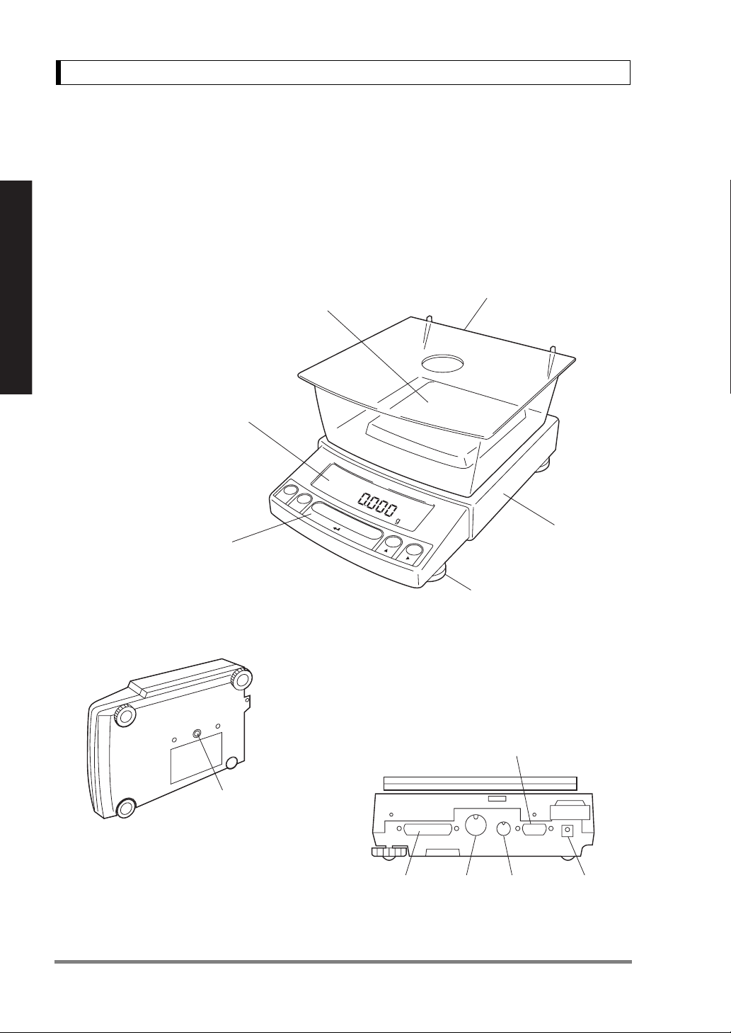
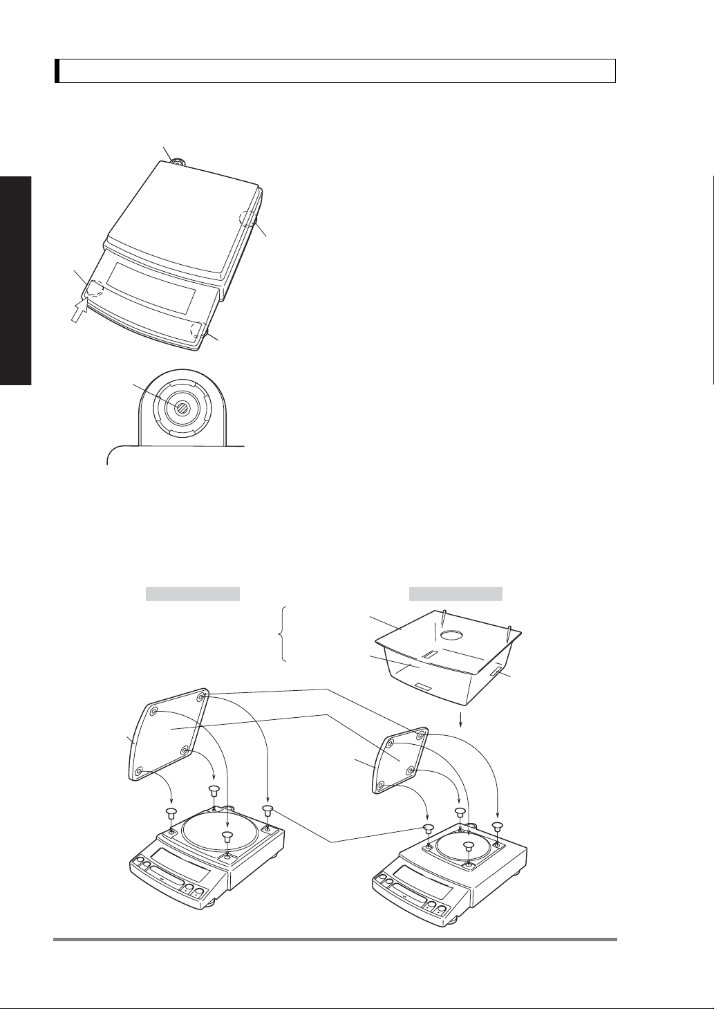
2.1 Components
Windbreak set
Pan
(Supports the object to be weighed)
Display panel
(Shows weighed result, information on
Read These Pages Before Installation
programming function, indicates current
setting, working function, necessary operation,
and error message)
(Included with models with minimum display of 0.001g.
Prevents possible affect by air flow)
Operation keys
(Used to tare, execute calibration
and functions, program functions,
input numerical values)
Below-weigh hook cap
Below-weigh hook cap
Main body
Level screws
(Adjust to level the balance)
Figure shows a small pan model with a windbreak set.
KEY Connector
RS-232C
Connector
DATA I/O
Connector
AUX
Connector
DC IN
Connecto
(Connectors on the back)
2
2. Name and Function of Components
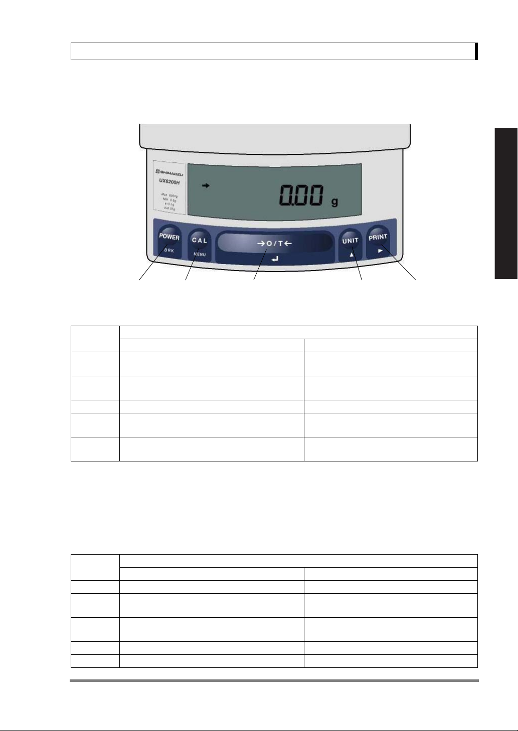
2.2 Key Panel and Operation
[POWER] key [CAL] key [O/T] key [UNIT] key [PRINT] key
Functions of the keys
Read These Pages Before Installation
Key
[POWER]
[CAL]
[O/T] Tares the balance. (Displays zero.) (*2) Displays the Pretare value.
[UNIT]
[PRINT] Sends the displayed value to a peripheral device.
*1 This key is used to set values when percent (%), number (PCS), solid specific gravity (Td), or liquid specific
gravity (d) are displayed.
*2 When a Pretare value is set, zero is not displayed and [- Pretare value] is displayed.
*3 Units other than “g” must be set up before they can be used for measurement. Only gram (g), percent (%), and
piece counting (PCS) are set-up before shipment. To set up other units or specific gravity measurement, refer
to section 12., or 14.1, 14.2.
*4 When the unit is set to 10d, the resolution of the minimum display is decreased by one decimal place.
Key
[POWER] Returns to the previous menu level Returns to the mass display.
[CAL] Moves to the next menu item.
[O/T]
[UNIT] Increases the numeric value of the blinking digit by 1. No operation.
[PRINT] Moves to the next digit during numeric value entry. No operation.
Switches between the operation and standby
modes.
Enters span calibration or menu item selection.
(*1)
Changes the weighing unit or selects specific
gravity measurement. (*3)
Selects or sets the currently displayed menu item,
or enter into the displayed menu.
Press Once and Release Press and Hold for About 3 Seconds
Press Once and Release Press and Hold for About 3 Seconds
During Weighing
Exits the application function and returns to
the mass display.
Displays the last menu item that was set.
(Last menu recall)
Switches between the 1d and 10d display. (*4)
Sends the date and time to a peripheral
device.
During Menu Item Selection
Displays the last menu item that was set.
(Last Menu Recall)
No operation.
3
2. Name and Function of Components
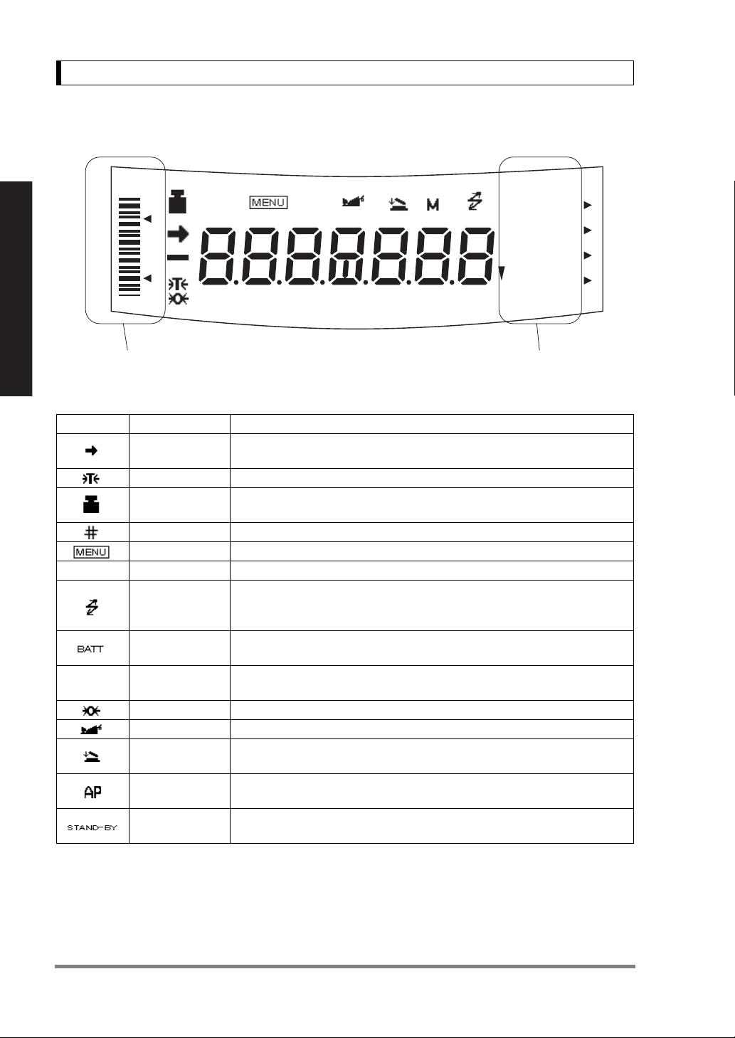
2.3 Balance Display and Function
HI
GO
LO
Analog display section Unit display section
Read These Pages Before Installation
Display Name Description
Stability mark
Tare symbol Indicates that a Pretare value has been set.
∗ Asterisk Indicates that the displayed numeric value is not a mass value.
Weight symbol
Number symbol Indicates numeric value entry.
Menu symbol Indicates that the menu lock is on. Illuminates during menu item selection.
Communication
Battery symbol
T
*1 Stability symbol
The displayed value may change while the stability symbol remains illuminated if the load is changing slowly or
if the stability detection band has been set to a large value.
Inverse triangle
Zero symbol Indicates the set-up of Auto Zero function.
Animal symbol Indicates the set-up of Animal Weighing function.
Auto-Memory &
Zeroing symbol
Stand-by symbol Illuminates when the balance power is in the standby mode.
symbol
symbol
Auto Print
symbol
# ∗
%NETBPTG
PCS lbGN
mg mom
ctdwt
kg
BATT
AP WARM-UP STAND-BY
Indicates that the weighed value is stable. (*1) In menu item selection, indicates currently selected item.
Illuminates during span calibration. In menu selection, indicates setting
related to calibration. Blinks before automatic span calibration starts.
Illuminates during communication to external equipment through the RS232C or DATA I/O connector. In menu selection, indicates setting related to
communication.
When the balance is operated with the optional battery pack, this symbol illuminates to indicate that the battery voltage has dropped.
Indicates the set-up of solid specific gravity measurement. Used as a substitute for the decimal point.
Indicates the set-up of Auto-Memory and Zeroing.
Indicates the set-up of Auto Print function.
Also illuminates when the application function has entered the standby mode.
oztl
4

3. Specifications
3. Specifications
UW Series Model UW220H UW420H UW620H UW2200H UW4200H UW6200H UW420S UW820S UW4200S UW8200S
Capacity 220g 420g 620g 2200g 4200g 6200g 420g 820g 4200g 8200g
Minimum display 0.001g 0.001g 0.001g 0.01g 0.01g 0.01g 0.01g 0.01g 0.1g 0.1g
Calibration range
with external weights
Repeatability (σ) ≤0.001g ≤0.01g ≤0.008g ≤0.08g
Linearity ±0.002g ±0.02g ±0.01g ±0.1g
Response time (s) 1.5 - 2.5 0.7 - 1.2
Ambient temperature (°C)
Temperature coefficient of sensitivity (ppm/°C) (10 - 30°C)
Pan size (mm) approx.
Main body dimensions (mm) approx.
Weight (kg) approx. 3.4 4.6 3.4 4.6
Display LCD with backlight
Power requirements DC, 10 to 15.5V, 500mA (plug polarity: center negative)
Data I/O RS-232C
Features
100 - 220g 100 - 420g 100 - 620g
108 X 105 170 X 180 108 X 105 170 X 180
Analog display, % display, PCS, User unit, Animal weighing, Specific gravity measurement S/W, Checkweighing
1000 - 2200g 1000 - 4200g 1000 - 6200g
5 - 40
±3 ±5
190W X 317D X 78H
WindowsDirect
PSC
Clock-CAL
GLP/GMP/ISO conformance
100 - 420g 100 - 820g
1000 - 4200g 1000 - 8200g
Read These Pages Before Installation
UX Series Model UX220H UX420H UX620H UX2200H UX4200H UX6200H UX420S UX820S UX4200S UX8200S
Capacity 220g 420g 620g 2200g 4200g 6200g 420g 820g 4200g 8200g
Minimum display 0.001g 0.001g 0.001g 0.01g 0.01g 0.01g 0.01g 0.01g 0.1g 0.1g
Calibration range
with external weights
Repeatability (σ) ≤0.001g ≤0.01g ≤0.008g ≤0.08g
Linearity ±0.002g ±0.02g ±0.01g ±0.1g
Response time (s) 1.5 - 2.5 0.7 - 1.2
Ambient temperature (°C)
Temperature coefficient of sensitivity (ppm/°C) (10 - 30°C)
Pan size (mm) approx.
Main body dimensions (mm) approx.
Weight (kg) approx. 2.7 2.9 2.7 2.9
Display LCD with backlight
Power requirement 12V 1A
Data I/O RS-232C
Features
100 - 220g 100 - 420g 100 - 620g
108 X 105 170 X 180 108 X 105 170 X 180
Analog display, % display, PCS, User unit, Animal weighing, Specific gravity measurement S/W, Checkweighing
1000 - 2200g 1000 - 4200g 1000 - 6200g
5 - 40
±3 ±5
190W X 317D X 78H
WindowsDirect
GLP/GMP/ISO conformance
100 - 420g 100 - 820g
1000 - 4200g 1000 - 8200g
5
4. Installation
4. Installation
4.1 Choosing the Installation Site
(1) Power supply
• Select an installation site that is near a power source to ensure that the attached AC adapter
is used properly. If this is not possible, an optional battery pack is available as a special
accessory.
• Verify that the supply power voltage conforms to that indicated on the AC adapter.
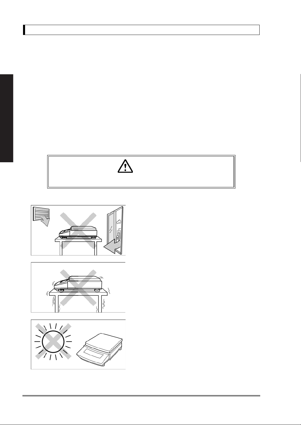
(2) Installation site
Read These Pages Before Installation
Caution
Avoid sites where the balance will be exposed to the following:
• Air flow from air-conditioner, open window, or venti-
lator
•Vibration
• Direct sunlight
(Continued)
6

4. Installation
• Extreme temperature, temperature changes or
humidity
• Corrosive or flammable gasses
• Dust, wind, electromagnetic waves, or magnetic fields
Large capacity balances should be installed on a sturdy floor and table that can support the total load
of the balance AND object to be weighed.
Read These Pages Before Installation
7
4. Installation
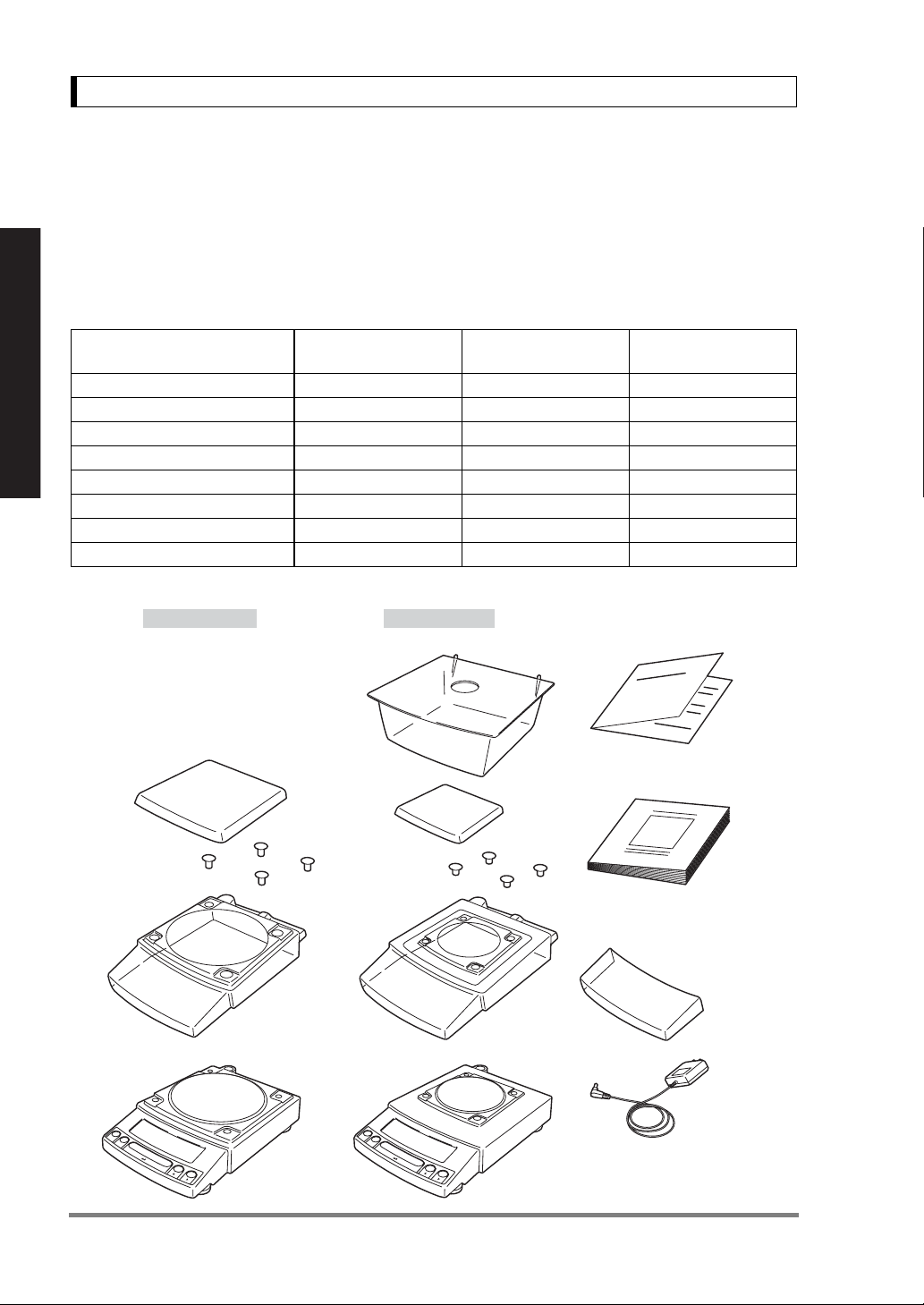
4.2 Unpacking and Delivery Inspection
Unpack and remove all the items from the delivery box. Check if all the listed items are present and
nothing has been damaged. Contact your local distributor in case of damaged or missing items.
Standard Packing List (Number of item)
Large pan model
Balance main body 111
Pan support cap 444
Pan 111
AC adapter 111
Protective in-use cover 111
Read These Pages Before Installation
Windbreak set 001
Instruction manual 111
Explanatory operation sheet 111
Large pan model Small pan model
Windbreak set
Pan
Small pan model
(Minimum display 0.01g)
Explanatory operation sheet
Small pan model
(Minimum display 0.001g)
Pan supporter caps
Protective
in-use cover*
Balance
main body
(The shape of the adapter supplied with
the balance may differ from this figure.)
Instruction manual
* Protective in-use
cover may be in
this shape.
AC adapter
8
4. Installation
4.3 Installation
(Start at step 3 when installing a UX series balance. Prepare a plus (+) screw driver for a UW series
balance.)
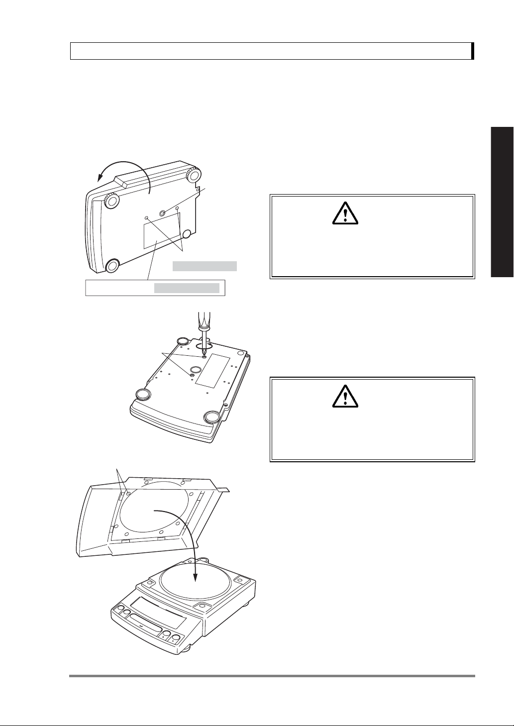
1 Place the balance main body upside down.
Below-weigh
hook cap
Transportation screws
(only for UW series)
Explanation label (only for UW series)
Transportation screws
(UW only)
Caution
Do not operate step 2 with the balance placed
on its side.
Place the balance on a smooth surface.
2 Referring to the explanation label on the bottom
of the balance, turn the two transportation screws
counterclockwise until they tighten again.
(UW only)
Read These Pages Before Installation
Double-sided tapes (16 places)
[ Large pan model]
Caution
When moving the balance again, turn the two
transportation screws clockwise until they
tighen. (UW only)
3 If you install the protective in-use cover, remove
the paper to expose the double-sided tapes on it
and place it on the balance main body. Press firm
so that the cover does not touch the pan.
[The shape of the protective in-use cover may be
different (See 4.2).]
9
4. Installation
r
Level
Level
screw
screw
Left front
Level indicator
Level indicator
Level screw
Level screw
(At the shortest
(At the shortest
point when
point when
starting
starting
adjustment)
adjustment)
Level screw
Level screw
4 Adjust the level.
This balance has four feet, three of which are
adjustable. For efficient level adjustment, follow
the procedure below.
(1) First, verify that all three leveling screws are at
their shortest point.
(2) While lightly pressing down on the left front of
the balance, turn both of the front leveling screws
to bring the air bubble into the center circle of the
level indicator.
(3) Finally, while still pressing down on the front of
the balance, adjust the leveling screw at the right
rear of the balance until the balance is stable.
Read These Pages Before Installation
Bubble
Large pan model Small pan model
Curved front
Level indicato
Windbreak set
5 Insert the four pan supporter caps into the
holes in the top of the balance. Place the pan on
top of them. Positioners of the pan must fit pan
supporter caps in this operation.
6 Before mounting the windbreak, remove the
paper to expose the double-sided tapes on it.
Attach the windbreak to the top of the balance.
The windbreak is a standard accessory for mod-
els with a minimum display of 0.001g.
Windbreak cover
Windbreak body
Positioners
Pan
Curved front
Double-sided tapes
(3 places)
10
Pan supporter caps
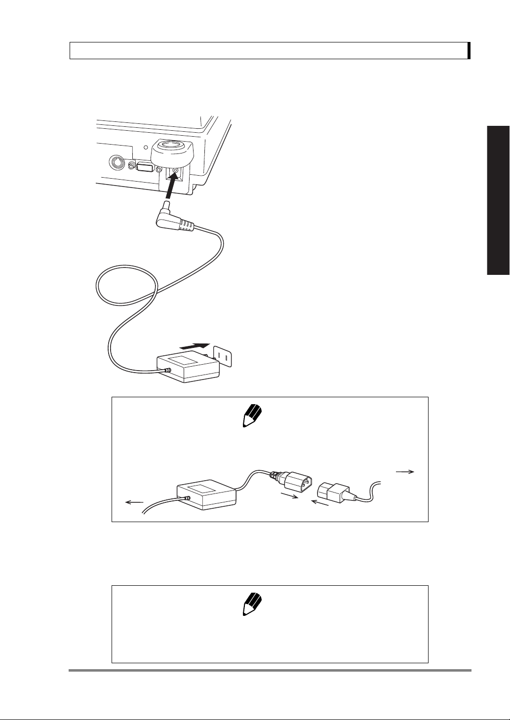
4.4 Turning ON the Power
1 Insert the plug of the AC adapter into the DC IN
connector on the rear of the balance.
2 Insert the AC adapter into the power source.
The balance self-check is activated and the fol-
lowing messages are displayed in the order indi-
cated. [HELLo], [CHE 5], [CHE 4], [CHE 3],
[CHE2], [CHE1], [CHE0], whole lighting, [oFF]
([CHE 5] and [CHE 4] are not displayed for the UX
series).
4. Installation
Read These Pages Before Installation
Note
A power cable may be necessary to connect the AC adapter to the power
source, depending on the type of the AC adapter.
AC Adapter
Balance
Power Source
Power cable
3 Press [POWER] key. The whole display illumi-
nates and then the display changes to indicate
the gram-display. The backlight is illuminated.
Note
When using the optional battery pack (special accessory), connect the fully
charged battery pack to the DC IN connector of the balance using the cable
attached to the battery pack.
11
4. Installation
4.5 Span Calibration
It is necessary to calibrate the balance after it is moved.
Verify that the balance is stable before performing the span calibration. To achieve a very stable state,
ensure that the balance has been turned on with the gram-display for at least one hour, that the tem-
perature is constant, that there are no breezes or vibrations and that the balance is in an area isolated
from the normal traffic flow.
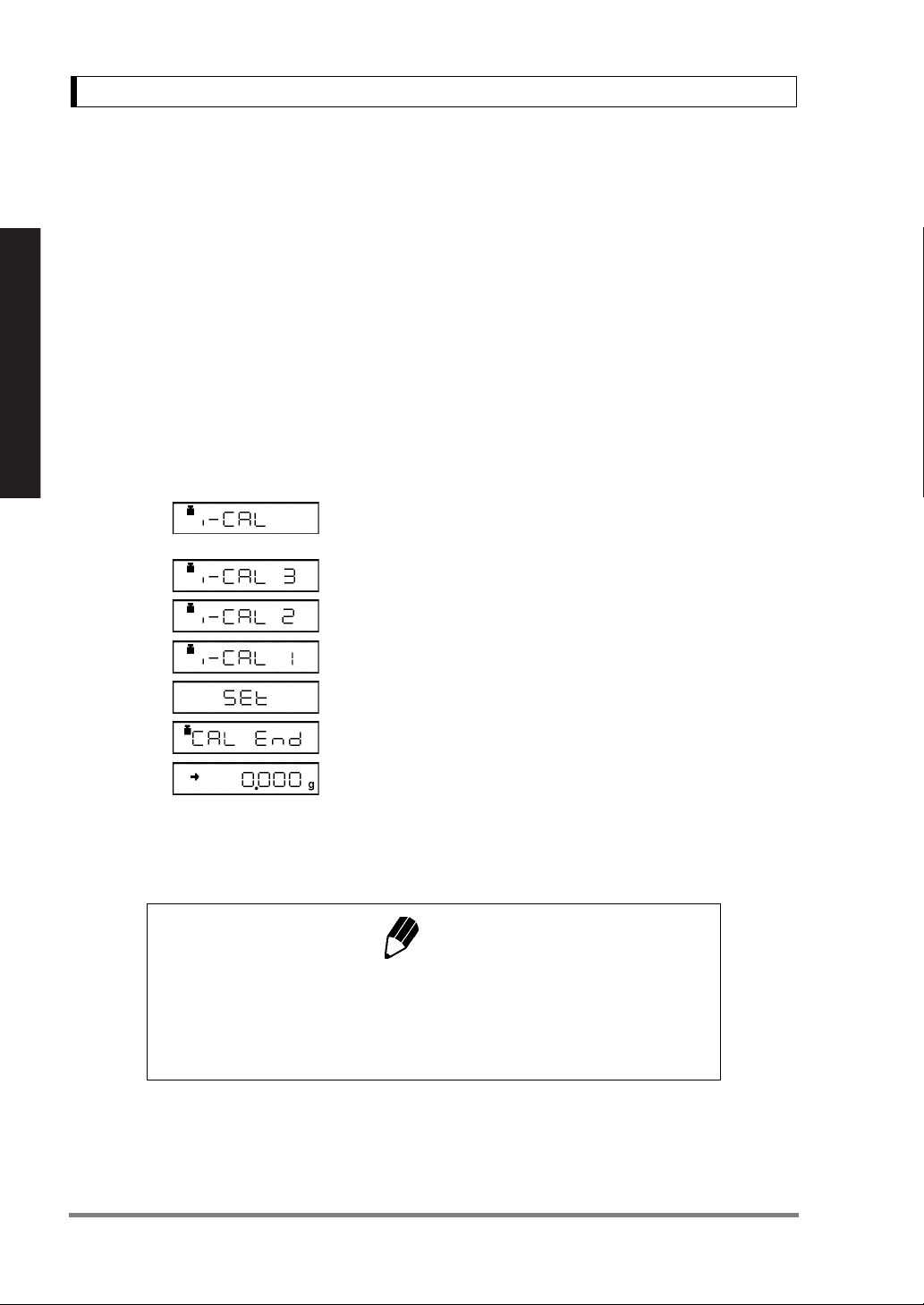
UW series [Span Calibration Using the Built-
in Weight]
1 Verify that the balance is in gram-display and
that the pan is empty.
Read These Pages Before Installation
2 Press the [CAL] key once. “i-CAL” is displayed.
3 Press the [O/T] key. After “i-CAL3”...“i-CAL1”,
“Set”, “CALEnd” are displayed indicating the com-
pletion of span calibration, the gram-display will
appear.
This is the standard calibration type. Refer to 10.3.1 for use of external weights.
Note
Span calibration is required again :
when the location of the balance is changed,
when the room temperature changes considerably,
periodically, according to the quality control plan of the user.
12
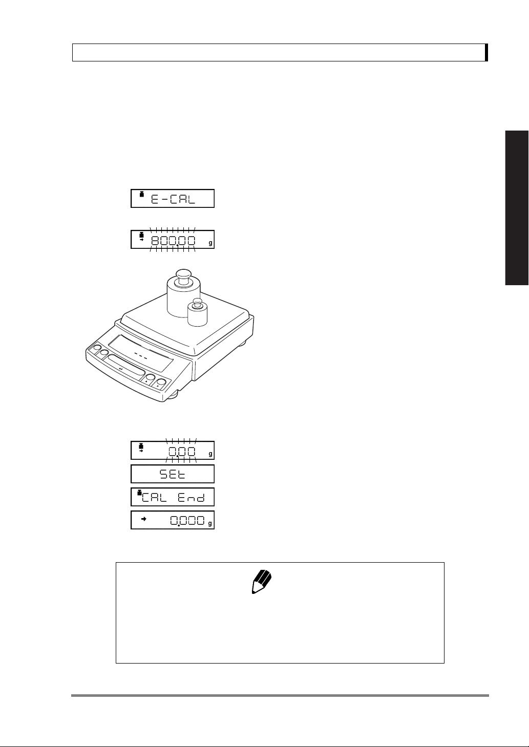
(Example)
4. Installation
UX series [Span Calibration Using External
Weights]
1 Verify that the balance is in gram-display and
unload the sample from the pan.
2 Press the [CAL] key once. “E-CAL” is displayed.
3 Press the [O/T] key.
The value of the correct calibration weight to be
loaded is displayed and blinks.
4 Load the indicated calibration weight and press
the [O/T] key.
5 When the zero display blinks, unload the weight
from the pan and press the [O/T] key. “Set” is dis-
played briefly to indicate completion of span cali-
bration. Then the gram-display will return.
Read These Pages Before Installation
Note
Span calibration is required again :
when the location of the balance is changed,
when the room temperature changes considerably,
periodically, according to the quality control plan of the user.
13

5. Basic Operation
5. Basic Operation
5.1 Weighing
Read These Pages Before Installation
1 If a weighing vessel (tare) is used, place it on
the pan and wait for the stability mark to illumi-
nate.
2 Press the [O/T] key to zero the display. (This
operation is called “taring”.)
Error Displays During Weighing
Overload: Weighing capacity has been exceeded.
Negative Overload: The load on the balance is too light.
The pan is not adjusted properly.
For D-type balances, [-oL] will appear if the load is below the low capacity range.
3 Place the object to be weighed on the pan.
4 Read the displayed value after the stability
mark is displayed.
14

5. Basic Operation
5.2 Changing the Unit Display
Every time the [UNIT] key is pressed, the unit display changes sequentially among those set-up in
12.1 Unit Display Set-up. Gram, %, and PCS have been set-up before delivery.
Notes
• Before a unit can be displayed it must be registered in 12.1 Unit Display
Set-up.
• The registered units are displayed sequentially according to the order of
the 12.1 Unit Display Set-up.
Read These Pages Before Installation
15
6. WindowsDirect Function
6. WindowsDirect Function
6.1 Introduction: Experience it!
The UW/UX series balance can transfer data directly to a personal computer running Lotus 1-2-3,
Excel, or other applications running on a Windows
typed from the keyboard. This function is called WindowsDirect. Because this function directly
accesses the Windows
nated. A cable and a few simple settings are all that is needed to enable data transmission from the
balance.
®
operating system, communication software-installation troubles are elimi-
6.2 Set Up WindowsDirect
Simple settings are made for the balance and the computer. Connection is by RS-232C cable specified
by shimadzu.
6.2.1 Setting Up the Balance
®
* operating system, as if the displayed value were
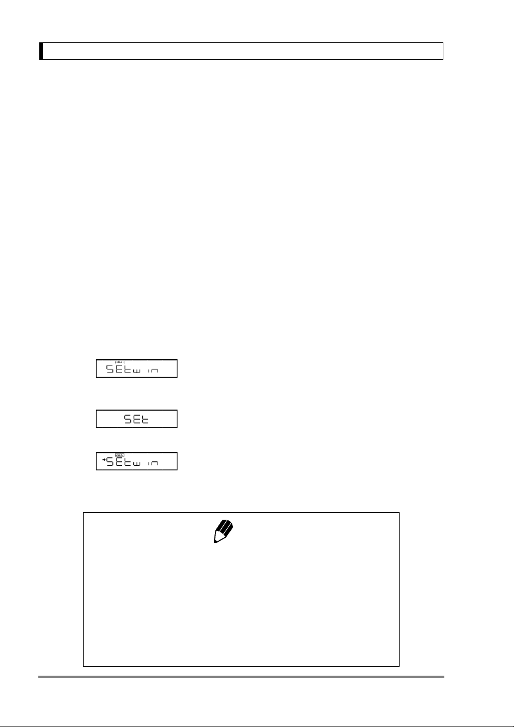
1 Press the [MENU] key twice from the gram-dis-
play. “Setwin” appears.
2 Press the [O/T] key. Verify the stability mark is
illuminated with “Setwin” display. All the communi-
cation settings for WindowsDirect have been made.
3 Go to “STAND-BY” by pressing the [POWER]
key several times and unplug the AC adapter
from the balance. Unpluging the balance once is
necessary after the above setting.
Note
When WindowsDirect settings are made using the "SEtwin" setting, indi-
vidual communications parameters can be changed using the Communi-
cations Settings menu (15.3). In this case, the → (stability mark) may still
appear with the "SEtwin" display but WindowsDirect may not operate. To
restore WindowsDirect optimal settings first go to the "SEtwin" display and
remove the stability mark by pressing the [O/T] key. This restores the
default Communications settings. Then, reset "SEtwin" following the pro-
cedure described in 6.2.1.
16
6.2.2 Cable Connection
6. WindowsDirect Function
1 Verify the balance display is “STAND-BY”.
2 Turn off the computer and disconnect the
power cord from the balance.
3 Connect the RS-232C cable to the balance.
RS-232C Connector
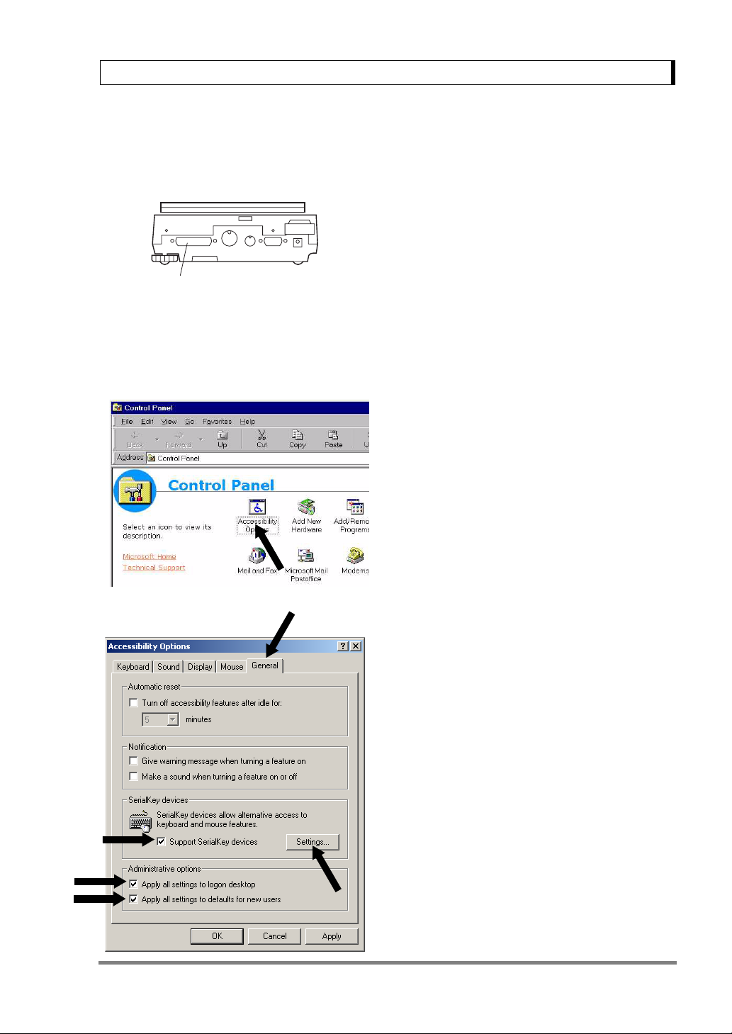
6.2.3 Setting Up the Computer
(leave the balance unplugged)
4 Connect the RS-232C cable to the computer.
1 Turn ON the power to the computer and start
Windows
®
*.
2 Click “Start”, choose “Settings”, and “Control
Panel”.
3 Select “Accessibility Options.”
4 Verify that there are no check marks for any
items on all five tabs including “General.”
5 Put a check mark at “Support Serialkey device”
in the “General” tab. This should be the only
check mark on all the tabs of Accessibility Options
unless “Administrative options” appears in the
“General” tab. Put check marks at both the items
of “Administrative options” to maintain the set-
tings even after restarting Windows
®
.
6 Open “Settings”.
17
6. WindowsDirect Function
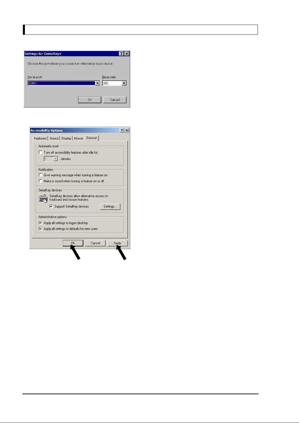
7 Select the serial port corresponding to the RS-
232C port of your personal computer. (Serial port:
any one of COM1 to 4. Usually, COM1)
8 Select a “Baud rate” of 300.
9 Click “OK”.
10 Click “Apply” and wait.
11 Click “OK”.
18
12 Click “Start”, point to “Shut Down” then select
“Restart the computer?”.
It is not necessary to perform the Windows
trol panel setting operation every time.
®
con-
6.2.4 Start and Checking Operation
6. WindowsDirect Function
1 Start Windows
2 After Windows
nect power cord from the AC adapter to the bal-
ance, when “oFF” is displayed, press the
[POWER] key. The mass display appears.
®
.
®
has completely started, con-
Note
Turning ON the balance before Windows®* is completely activated may
cause incorrect operation.
3 Open the “Note pad” accessory in Windows
(or start the application you wish to use).
4 Press the [PRINT] key of the balance.
Verify that the numeric value displayed on the bal-
ance appears at the cursor position on the screen
of computer. The effect is the same as typing the
value from the computer keyboard and pressing
the ENTER key. Characteristics indicating the unit
of measure are not sent to the computer.
®
*
Windows
5 Test combination with Auto Print function, if you
wish to use it.
6 End the operation using the standard close or
exit procedure.
®
* = Windows® 95, Windows® 98, Windows® Me, Windows® 2000, and higher.
19

6. WindowsDirect Function
6.3 Troubleshooting
• This function may not operate on a computer on which a normal U.S.
version of Microsoft Windows
sonal computers may not be able to use this function or some features
may be limited. Shimadzu does not guarantee that this function can be
used on all computers without any problems currently or in the future.
• Shimadzu is not liable for any direct or indirect problems caused by this
function. It is recommended that important data or programs on your
computer be backed-up before using this function. For the operation of
Windows
priate instruction manual.
• It is necessary to have the “Accessibility Options” function of Windows
installed on the PC. To install “Accessibility Options”, select “Start” →
“Setting” → “Control panel” → “Add /Remove Programs” and open the
“Windows
For more information, see the Windows
• When “Support Serialkey device” is selected in Accessability Options,
software which uses the same RS-232C port on that computer does not
operate correctly, until Serialkey support is discontinued. If another
device (an external modem, plotter or etc.) is to be connected, remove
the check mark placed on “Support Serialkey device” and re-activate
Windows
®
* or the computer, refer to commercial tutorials or the appro-
®
Setup” tab. Place a check mark on “Accessibility Options.”
®
after the balance is disconnected.
Notes
®
* does not operate. Some types of per-
®
* instruction manual.
®
*
When the WindowsDirect Function Does Not Operate At All:
• For some notebook computers, it is possible to shut off the RS-232C port for energy saving pur-
poses. Set the computer so that the RS-232C port can be used.
• Try different COM port settings from 1 to 4. Re-start Windows
®
* after each setting change.
• Verify that the correct RS-232C cable is being used.
For Windows
For Windows
®
98 and higher, try setting the computer again without restarting.
®
95 Version 4.00.950B, see A-8., “Compatibility Notification Regarding Linking of “Win-
dowsDirect” Function with WindowsR95 Version 4.00.950B.”.
Communication through LAN by other applications may interfere with Serialkey device set-up. Try with-
out LAN connection.
Windows
®
* = Windows® 95, Windows® 98, Windows® Me, Windows® 2000, and higher.
20
6. WindowsDirect Function
When the WindowsDirect Function Intermittently Malfunctions:
• Use a communication speed of 300bps. Depending on the processing ability of the computer, this
function may operate incorrectly if communication speed is too high.
• Send the next data only after the current one is displayed on the screen. Depending on the process-
ing ability of the PC, this function may operate incorrectly if the interval of data transmission is too
short.
• Do not touch the keyboard or the mouse while the balance is transmitting data.
• Stop the data transmission and confirm that no data is entering the computer before touching the
keyboard or the mouse.
Notes
• This function may generate incorrect data when the displayed value is
not a weight value (i.e. error code or time).
• The unit designation is not transmitted. The balance display unit
selected and the unit required by the application should be set the
same.
• This function may operate incorrectly depending on the settings of vari-
ous lock keys of the keyboard such as the NUMLOCK or cursor key
lock. Change the state of the lock and function keys on the computer
keyboard.
• Peripheral devices connected to the DATA I/O such as Electric Printer
EP-50 cannot be used with this function.
• When this function is used, a command cannot be sent from the periph-
eral device or computer to the balance.
• Set the data formats, such as decimal places and units, according to
each application.
21
 Loading...