

Page 1

Clarity Controls
Shimadzu LC-10/20 System
LC + DET + AS + CO ENG
Code/Rev.: M108/70B
Date: 11/30/2016
Phone: +420 251 013 400 DataApex Ltd.
Fax: +420 251 013 401 Petrzilkova 2583/13
clarity@dataapex.com 158 00 Prague 5
www.dataapex.com The Czech Republic
Page 2

Clarity®, DataApex®and
®
are trademarks of DataApex Ltd. Microsoft®and Windows
TM
are
trademarks of Microsoft Corporation.
DataApex reserves the right to make changes to manuals without prior notice. Updated manuals can be
downloaded from www.dataapex.com.
Author: DM
Page 3

Shimadzu LC-10/20 System Table of Contents
Contents
1 Shimadzu LC-10/20 System 1
2 Requirements 3
2.1 Minimal version of device firmware required 4
3 Installation Procedure 5
3.1 Shimadzu LC-10/20 System communication 5
3.2 Software Installation 7
3.3 Clarity Configuration 8
3.4 Shimadzu LC-10/20 System Setup 11
3.4.1 Shimadzu LC-10/20 System Setup - Setup 12
3.4.2 Shimadzu LC-10/20 System Setup - Controller 14
4 Using the control module 16
4.1 Pump 17
4.1.1 Shimadzu LC-10/20 System Setup - Pump 17
4.1.2 Method Setup - LC Gradient 19
4.1.2.1 Gradient Options 21
4.1.3 Method Setup - LC 23
4.1.4 Method Setup - Advanced 26
4.1.5 Device Monitor 27
4.1.6 Report Setup 29
4.2 Detector 30
4.2.1 Shimadzu LC-10/20 System Setup - Detector 30
4.2.2 Method Setup - Acquisition - Detector 32
4.2.2.1 Method Setup - Acquisition - RF Detector 34
4.2.2.2 Method Setup - Acquisition - RID Detector 36
4.2.3 Method Setup - Acquisition - Time Program 38
4.2.4 Method Setup - Acquisition - Analog Output 40
4.2.5 Device Monitor 41
4.2.6 Report Setup 43
4.3 Autosampler 45
4.3.1 Shimadzu LC-10/20 System Setup - Autosampler 45
4.3.2 Method Setup - AS - Sampler 47
4.3.2.1 Method Setup - AS - Sampler (SIL-10Axl) 49
4.3.2.2 Method Setup - AS - Sampler (SIL-10AF) 50
4.3.3 Method Setup - AS - Time Program 51
4.3.4 Method Setup - AS - Pretreatment 52
4.3.5 Device Monitor - Shimadzu LC-10/20 System 56
4.3.6 Report Setup 57
4.4 PDA 58
4.4.1 Shimadzu LC-10/20 System Setup - PDA Detector 58
4.4.2 Method Setup - PDA 60
4.4.3 Method Setup - Acquisition 62
4.4.4 Device Monitor 63
4.4.5 Report Setup 64
4.5 Thermostat 65
- i -
Page 4

Table of Contents Clarity Controls
4.5.1 Shimadzu LC-10/20 System Setup - Thermostat 65
4.5.2 Method Setup - Thermostat - Thermostat 66
4.5.3 Method Setup - Thermostat - Time Program 67
4.5.4 Device Monitor 68
4.5.5 Report Setup 69
5 Troubleshooting 70
6 Vial Plate Numbers 71
- ii -
Page 5

Shimadzu LC-10/20 System Table of Contents
To facilitate the orientation in the Shimadzu LC- 10/20 System manual and Clarity
chromatography station, different fonts are used throughout the manual. Meanings of these fonts
are:
Instrument (blue text) marks the name of the window to which the text refers.
Open File(italics) describes the commands and names of fields in Clarity, parameters that can
be entered into them or a window or dialog name (when you already are in the topic describing
the window).
WORK1 (capitals) indicates the name of the fileand/or directory.
ACTIVE (capital italics) marks the state of the station or its part.
The bold text is sometimes also used for important parts of the text and the name of the Clarity
station. Moreover, some sections are written in format other than normal text. These sections are
formatted as follows:
Note: Notifies the reader of relevant information.
Caution: Warns the user of possibly dangerous or very important
information.
▌ Marks the problem statement or trouble question.
Description: Presents more detailed information on the problem, describes its causes,
etc.
Solution: Marks the response to the question, presents a procedure how to remove it.
- iii -
Page 6

Page 7
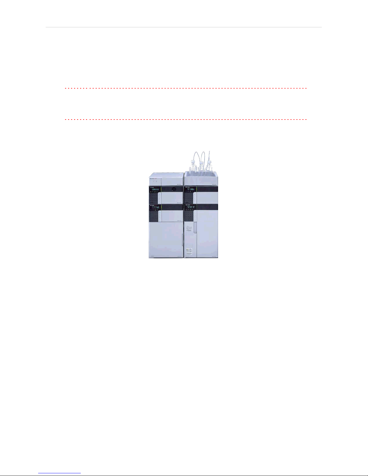
Shimadzu LC-10/20 System 1 Shimadzu LC-10/20 System
1 Shimadzu LC-10/20 System
This manual describes the setting of the Shimadzu LC-10/20 System.
The control module enables direct control of the instrument over serial line
or LAN (in case of LC-20 series).
Caution: The Shimadzu LC-10/20 System control module can not be combined
with Shimadzu LC- 10/20 Pump control module on a single PC where
Microsoft .NET Framework is installed.
Caution: A single Clarity station can only control one Shimadzu LC- 10/20
System. This is the restriction of MIMIC libraries used to perform the
instrument control.
Fig 1: Shimadzu Prominence system
As opposed to the Shimadzu LC- 10/20 Pump , this control module
operates the whole system (including detectors, autosampler, thermostat
etc.), not just the pump, but requires any of the supported controllers for
the operation of any other modules. Direct control means that the system
can be completely controlled from the Clarity environment. Instrument
method controlling the analysis conditions will be saved in the measured
chromatograms. Clarity can currently control following modules:
Controllers: SCL-10Avp, CBM-20A, CBM-20ALite
Pumps: LC- 6AD, LC-8A, LC-10AD, LC-10AS, LC- 10AT, LC- 10Ai, LC-
10ADvp, LC-10ATvp, LC-20AT*, LC-20AD*, LC-20ADXR*, LC-20AB*, LC20AS*
Detectors: SPD- 10A, SPD- 10Ai, SPD- 10AV, SPD- 10Avi, SPD- 10Avp,
SPD-10AVvp, SPD-20A*, SPD-20AV*, RID-10A, RID-20A**, RF-10A, RF10Axl, RF-20A**, RF-20Axs**
Autosamplers: SIL- 10ADvp, SIL- 10AF, SIL- 10Axl, SIL- HTA, SIL- HTC,
SIL- 20A*, SIL- 20AC*, SIL- 20AHT*°, SIL- 20ACHT*°, SIL- 20AXR*, SIL20ACXR*
PDA Detectors: SPD-M10Avp***, SPD-M20A*
- 1 -
Page 8

1 Shimadzu LC-10/20 System Clarity Controls
Thermostats: CTO-10A, CTO-10AC, CTO- 10Avp, CTO-10ACvp, CTO10ASvp, CTO-20A*, CTO-20AC*
The list continues to extend, for up to date list see the website
www.dataapex.com. Some devices also require a firmware of particular
minimal version for proper communication with Clarity(for more details
see the chapter Minimal version of device firmware required on pg 4).
* Devices marked with the asterisk will show in the System Configuration
dialog only after the CBM-20A (Lite) controller has been selected.
Caution: If any device from the LC-20 (Prominence) line is to be used with the
LC-10 line Controller, it is necessary to set it to the LC- 10 emulation
mode. This is done (for example on the LC-20AD pump) on the devices
display by pressing the VP key until the CALIBRATION screen appears.
Then press func key, enter the password and keep pressing the func
key until OP MODE screen shows. There, select the correct type of the
controller installed. Later in the System Configuration dialog it is
necessary to set the LC-20AD pump as LC-10AD when selecting the type
of the pump in the Shimadzu LC-10/20 System setup.
° The autosamplers SIL-20AHT and SIL-20ACHT marked with the circle
do not possess their specific option in the Shimadzu LC- 10/20 System
Autosampler dialog. In case of SIL-20AHT autosampler is present it
should be configured through SIL- 20A option. If the SIL- 20ACHT
autosampler is present it is necessary to configure it through SIL-20AC
option.
** RID-20A, RF-20A and RF-20AXS detectors must be always switched to
the LC- 10 emulation mode in order to be controlled (using MIMIC
libraries) in Clarity.
*** SPD-M10Avp PDA detector is not supported on 64-bit Windows.
RF-10AXL and RF-20AXS ( RF-20AXS with minimum firmware version
2.02) fluorescence detectors can be configured as a stand-alone control
module developed through Knauer company. This control module for RF-
10AXL and RF- 20AXS fluorescence detectors supports serial
communication via special RS232 cable (p/n SK 11) . If the RF-20A
detector was purchased through Knauer company (with special oem
firmware version) it can be connected to Clarity with above mentioned
special RS232 serial cable and controlled with above mentioned specific
control module.
Clarity does not control following controllers: CBM-10A, SCL-10A.
- 2 -
Page 9

Shimadzu LC-10/20 System 2 Requirements
2 Requirements
l Clarity installation CD ROM with LC control module (p/n A24) allowed.
Other parts of the system may need other modules or extensions, namely
the autosampler will need the AS control module (p/n A26) and the PDA
Detector will need the PDA extension (p/n A29) to operate.
l Supported Shimadzu system controller (see the full list of supported
controllers in the chapter "Shimadzu LC-10/20 System" on pg 1.). The
controller is needed even for the control of standalone PDA detector.
l Free serial port in the PC.
Note: Modern computers usually have only 1 (if any) serial (COM) port installed.
To use more devices requiring the RS232 port, the MultiCOM adapter
(p/n MC01) isavailable.
l Standard RS232-compliant cross DB9F-DB9F serial cable (p/n SK01) or
cross LAN cable (p/n SK08) in case of LC-20 system.
Note: Cables are not part of Clarity Control Module. It is strongly
recommended to order required cables together with the Control Module.
l SCSI card for use of the SPD- M10Avp PDA detector. SPD-M20A PDA
detector uses LAN communication.
Caution: It is recommended to use Adaptec SCSIcards. Drivers for Adaptec's
cards are located on Clarity installation CD ROM in directory HW_
DRIVERS\ASPI2 . Read the README.TXT file before you install the
drivers.
Caution: SPD-M10Avp PDA detector is not supported on 64-bit Windows.
- 3 -
Page 10

2 Requirements Clarity Controls
2.1 Minimal version of device firmware required
Tab 1: Controllers :
Name of Device: Minimal version of firmware required:
SCL-10Avp 5.33
Subcontroller 5.20
OptionBox-L 3.2
Tab 2: Pumps :
Name of Device: Minimal version of firmware required:
LC-10ADvp 5.26
LC-10ATvp 5.27
LC-10Ai 3.1
LC-10AD 3.1
LC-10AT 3.1
LC-10AS 3.1
LC-8A 1.5
LC-6AD 1.4
Tab 3: Autosamplers :
Name of Device: Minimal version of firmware required:
SIL-10ADvp 5.32
SIL-HTA 6.02
SIL-HTC 6.02
Tab 4: Column Ovens :
Name of Device: Minimal version of firmware required:
CTO-10Avp 5.24
CTO-10ACvp 5.24
CTO-10ASvp 5.24
CTO-10A[C] 3.0
Tab 5: Detectors :
Name of Device: Minimal version of firmware required:
SPD-10Avp 5.22
SPD-10AVvp 5.22
SPD-10Ai 3.0
SPD-10Avi 3.0
SPD-10A 3.0
SPD-10AV 3.0
RF-20A, Axs 1.10
- 4 -
Page 11

Shimadzu LC-10/20 System 3 Installation Procedure
3 Installation Procedure
3.1 Shimadzu LC-10/20 System communication
Shimadzu LC-10/20 System may be controlled either via standard serial
cross DB9F-DB9F cable or via cross LAN cable, depending on the type of
connector present on the controller. LAN communication is only present
on LC-20 line controllers.
Serial Connection
The Shimadzu LC- 10/20 System is controlled by serial (RS232)
communication. It uses standard serial cross DB9F-DB9F cable described
in the picture.
Fig 2: Serial cross DB9F - DB9F cable
LAN connection
For direct connection between chromatograph and computer, the cross
LAN cable should be used. On the other hand, for the connection to the
network, the straight LAN cable might be necessary (with older switches)
instead.
Shimadzu SCL-10Avp settings
In the controller it is necessary to set the Classvp parameter (accessible
from the main menu via the system submenu (key 4, it is located on the
bottom of the list) to 5.x value. Other communication parameters set in the
controller should be:
Interface: RS-232C
Baud Rate: 19200
Level: Enhanced
Caution: Only COM ports up to COM9 are supported. Serial ports with higher
numbers cannot be used. This also means that the Shimadzu LC-10/20
System cannot be connected to the serial port on Net- PAD (COM101
and COM102).
- 5 -
Page 12

3 Installation Procedure Clarity Controls
LC-20 components with SCL-10Avp controller
Shimadzu LC- 20 components have to be set to the LC-10 emulation
mode when they should be working under the LC-10 controller. This is
done from the device's keyboard according to this procedure (procedure
presented on the LC-20 series pump, may differ slightly for other devices):
l Press the VP button on the devices's front keyboard until the
CALIBRATION inscription is shown on the display.
l Press the func button to enter the configuration. The password has to be
filled in.
Note: The default password is 00000.
l Press the func button repeatedly until the OP MODE inscription is shown
on the display.
l Enter the desired number (1 for the pump) to switch the device to the SCL-
10Avp emulation mode and press the enter button.
l Switch the device off and on again. The new communication parameters
should be saved and used.
The procedure is in detail described in the LC- 20 hardware manual
provided by the Shimadzu company.
CBM-20A(Lite) settings
It is necessary to set the communication parameters in the controller. From
Clarity version 2.6.5, the parameters are:
Communication Mode: ClassVP
Interface: RS232/Ethernet (depending on the desired connection type)
The exact procedure is described in the controllers hardware manual.
- 6 -
Page 13

Shimadzu LC-10/20 System 3 Installation Procedure
3.2 Software Installation
Caution: If the PDA detector is to be used, it is necessary to switch it on before the
computer is turned on. This way, the SCSI controller will be detected
automatically. When turned on later, the PDA has to be added manually
using the Add Hardware function from the Windows Control Panel.
Install (or re-install) the Clarity software from the installation CD.
l Insert the installation CD into the CD-ROM of the computer and start the
installation.
l Select the target directory and press the Next button.
l Select Custom installation. The control module for the Shimadzu LC-
10/20 System is automatically included in it.
l If the PDA detector is to be used, select the Detector Control option (its
icon is checked, but grayed) and either click the checkbox to change it to
checked (not grayed) state or press the Details… button and check the
Shimadzu PDA option there.
l Follow the instructions given by the installation procedure until the
installation procedure ends.
- 7 -
Page 14
3 Installation Procedure Clarity Controls
3.3 Clarity Configuration
Caution: If the PDA detector will be used, it must be switched on prior to starting the
computer.
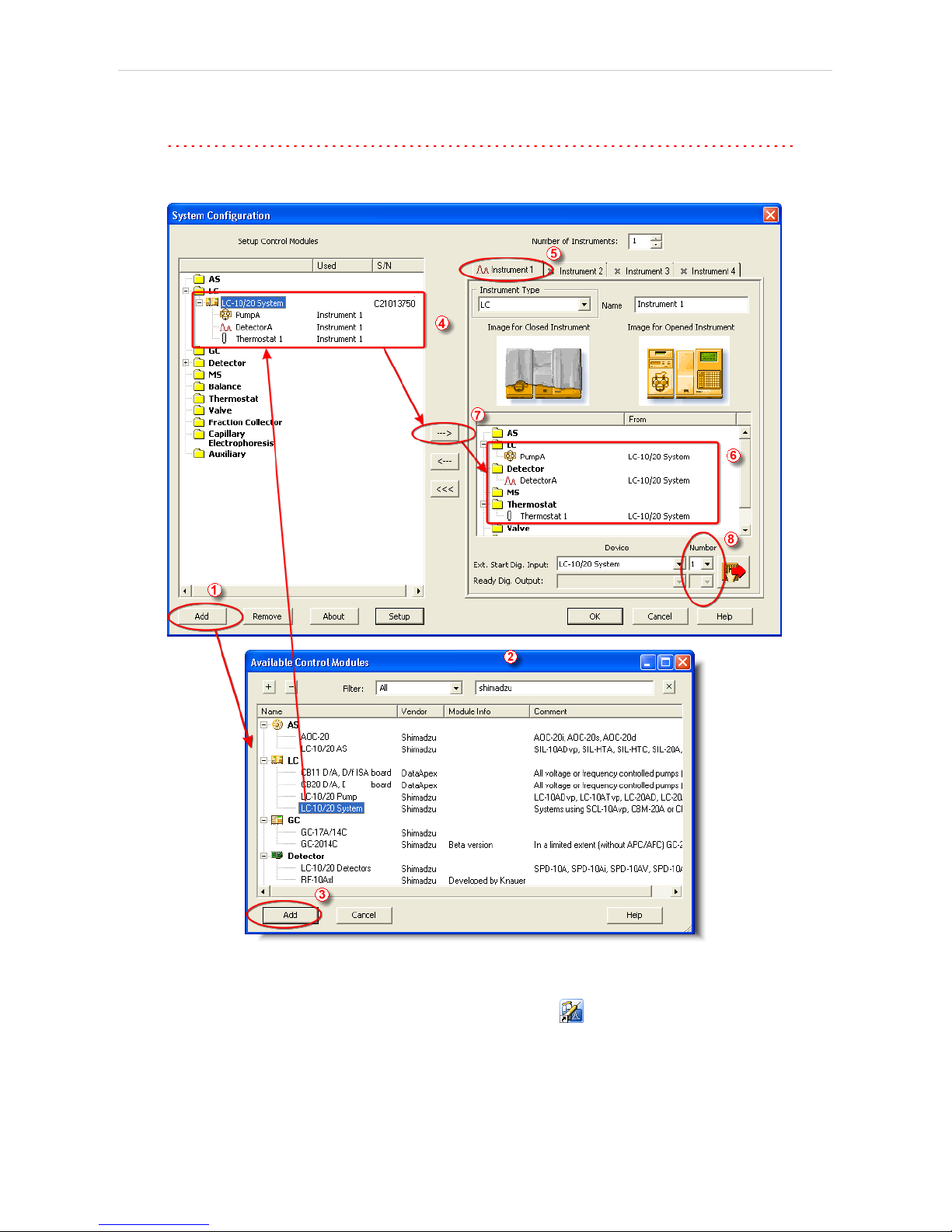
Fig 3: System Configuration
l
Start the Clarity station by clicking on the icon on the desktop.
l Invoke the System Configuration dialog accessible from the Clarity
window using the System - Configuration… command.
- 8 -
Page 15
Shimadzu LC-10/20 System 3 Installation Procedure
l Press the Add button ① (see Fig 3 on pg 8 .) to invoke the Available
Control Modules dialog.
l You can specify the searching filter ② to simplify the finding of the driver.
l Select the LC-10/20 System item and press the Add ③ button.
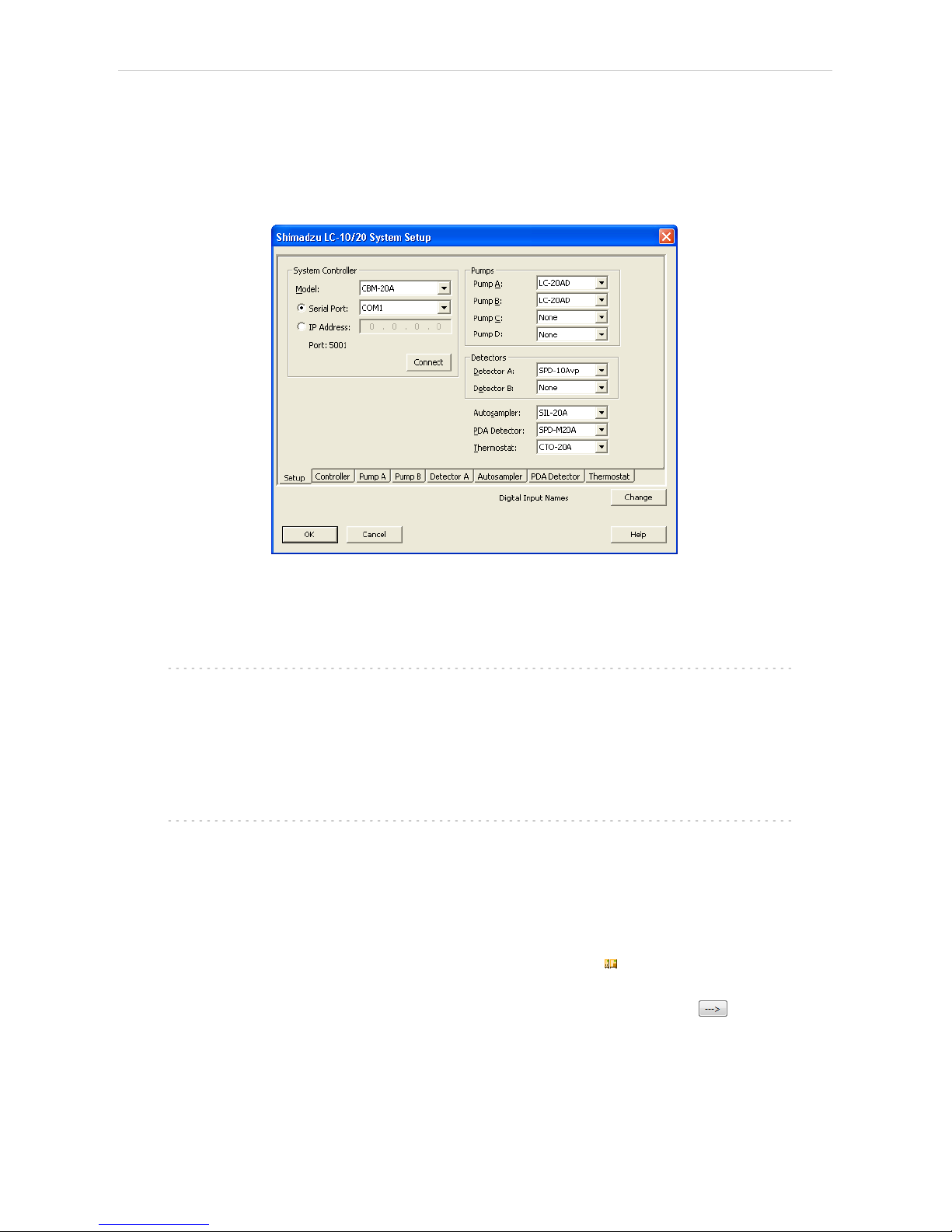
The Shimadzu LC-10/20 System Setup dialog will appear.
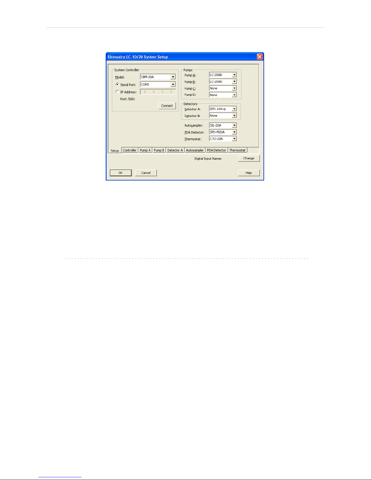
Fig 4: Shimadzu LC-10/20 System Setup
l Select the type of the controller in the Model field and the Serial Port or IP
Address to which the controller is connected.
Note: Only CBM- 20A and CBM- 20ALite controllers may be connected
through LAN.
l Select other parts of the system that are connected to the controller (such
as pumps, detectors, autosampler etc.). Each module selected will add its
own tab to the Shimadzu LC 10/20 System Setup dialog.
Note: Other fields and parameters of the Shimadzu LC- 10/20 System Setup
dialog are described later in the manual(for more details see the chapter
Shimadzu LC-10/20 System Setup - Setup on pg 12).
l Set the Instrument Type on the desired Instrument tab ④ to LC (or LC-
PDA when you want to use the PDA detector).
l Drag and drop the LC- 10/20 System icon from the Setup Control
Modules ④ list on the left side of the System Configuration dialog to the
desired Instrument ⑤ tab on the right side ⑥ (or use the button ⑦ to
do so).
- 9 -
Page 16

3 Installation Procedure Clarity Controls
Note: When you only change some of the already configured parts of the
Shimadzu LC-10/20 System, it is recommended to remove the system
from the given Instrument tab and add it there once more.
l Set the Ext. Start Dig. Input and Ready Dig. Output numbers ⑧ for your
acquisition card according to the wires being used for synchronization.
Caution: The Shimadzu LC- 10/20 System must have all subdevices configured
on the same Instrument (cannot have parts of it on different Instruments)
and no sub- device may be left unconfigured (if any subdevice is
configured on the Instrument, all subdevices must be).
- 10 -
Page 17
Shimadzu LC-10/20 System 3 Installation Procedure
3.4 Shimadzu LC-10/20 System Setup
Shimadzu LC-10/20 Pump Setup dialog (accessible through the System
Configuration dialog) is used to set the connection to the Shimadzu LC-
10/20 System , select it's configuration and set some other basic
parameters. The Setup tab is always opened by default.
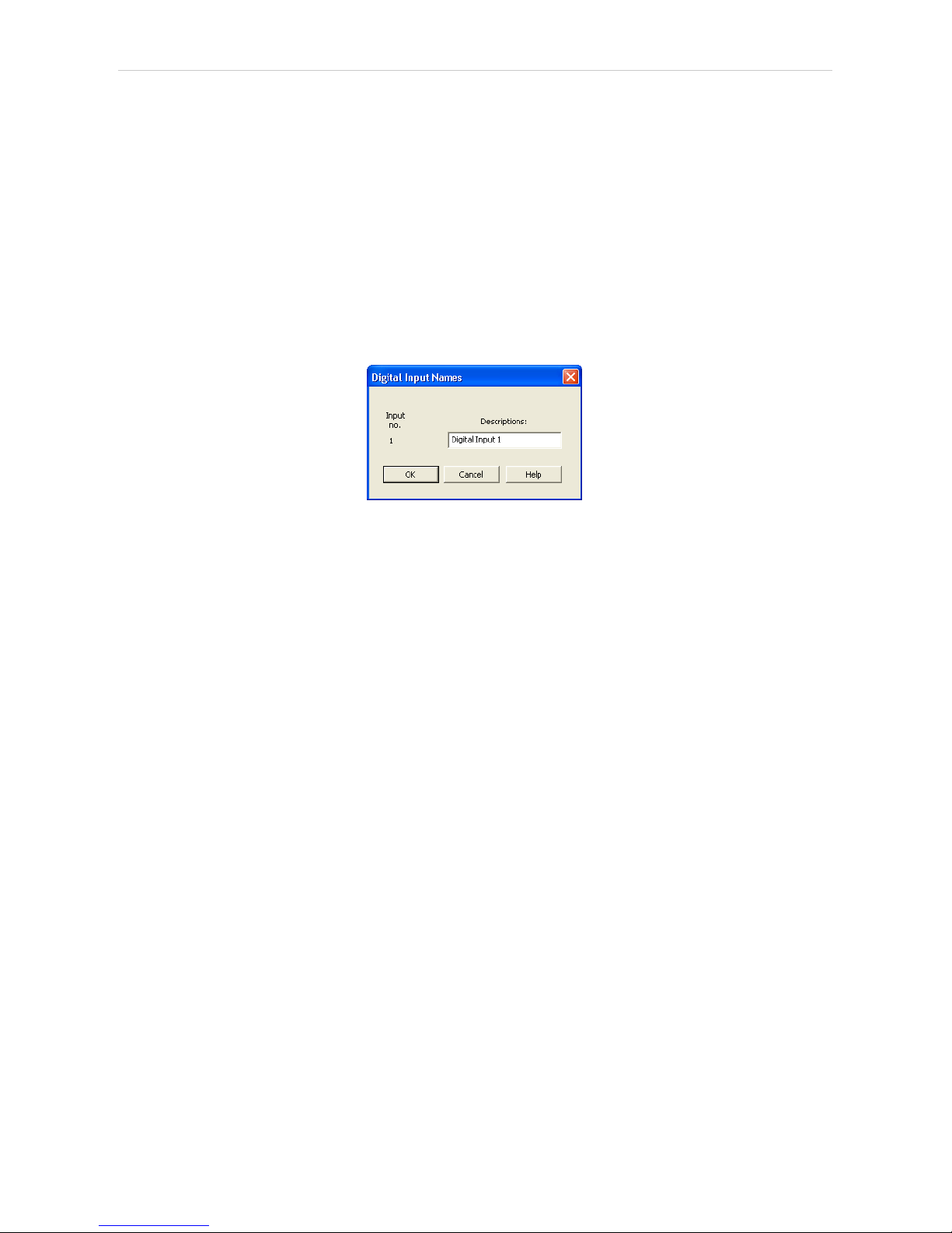
Digital Input Names
Pressing the Change button opens the Digital Input Names dialog which
allows to set the custom name for the virtual Shimadzu LC-10/20 System
digital input. This input allows to start Clarity run by the signal of the
Shimadzu LC-10/20 System controller.
Fig 5: Digital Input Names
- 11 -
Page 18
3 Installation Procedure Clarity Controls
3.4.1 Shimadzu LC-10/20 System Setup - Setup
Fig 6: Shimadzu LC-10/20 System Setup - Setup
System Controller
Section defining the type of the Shimadzu LC-10/20 System controller
and the connection to it.
Model
Sets the type of the controller unit. Only SCL-10Avp, CBM- 20A and
CBM-20ALite controllers are supported at the moment.
Note: The selection of the controller influences the number of options that will be
displayed when configuring other system devices. If any LC-20 modules
should be used with the SCL-10Avp controller, these devices have to be
switched to the LC- 10 emulation mode (for more details see the
chapter Installation Procedure on pg 5).
Serial Port
Selects the serial port to which the Shimadzu LC-10/20 System is
connected.
IP Address
Sets the IP Address if using the LAN connection. LAN can only be
used for the Shimadzu LC-20 controllers.
Connect
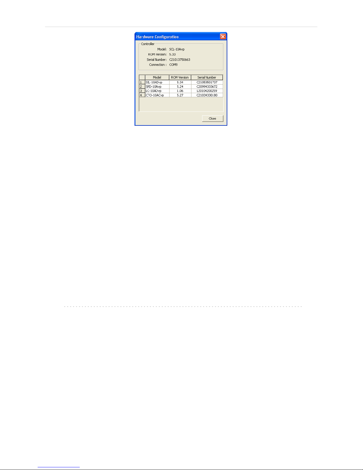
Tests the connection to the controller. If it is correctly set, the Hardware
Configuration dialog with all controller information and other
information on added modules will appear.
- 12 -
Page 19
Shimadzu LC-10/20 System 3 Installation Procedure
Fig 7: Hardware Configuration
Pumps
Sets the model of the pump connected. Up to three pumps may be
configured in a Shimadzu LC-10 and four pumps on Shimadzu LC-20
System.
The first pump may have valves configured, other pumps are not allowed
to have any valves. Any pump may be set as gradient or auxiliary, but
maximum of four solvents can be used in a gradient, so any further pumps
are automatically configured as auxiliary.
Detectors
Sets the model of the detector connected. Up to two detectors may be
configured in a Shimadzu LC-10/20 System.
Autosampler
Sets the model of the autosampler.
PDA Detector
Set the model of the PDA detector.
Thermostat
Sets the model of the thermostat.
Note: It is recommended to add the modules one by one and to check the
communication with the Connect button in between.
- 13 -
Page 20
3 Installation Procedure Clarity Controls
3.4.2 Shimadzu LC-10/20 System Setup - Controller
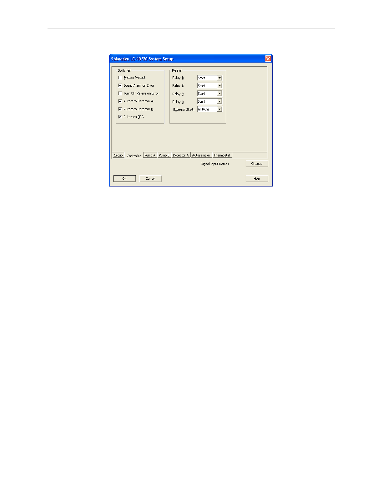
Fig 8: Shimadzu LC-10/20 System Setup - Controller
Switches
System Protect
While checked, in case of exceeding the maximal pressure the flow
rate will be decreased to one half of the set value. If unchecked, the
exceeding will shut-off the pump.
Sound Alarm on Error
Check to signalize error messages by sound.
Turn Off Relays on Error
If checked, in case of the controller error the AC power for devices
plugged in the multiple terminal box will be turned off.
Autozero Detector A (B)
If checked, the particular detector response will be set to zero at the
start of acquisition.
Autozero PDA
If checked, the PDA detector response will be set to zero at the start of
acquisition.
Relays
Relay 1 (..4)
These controls define the trigger criterion for each controller relay
outputs. Possible criteria are:
Start - Relay closed at the beginning of the analysis.
Stop - Relay closed at the end of the analysis or time program.
Error - Relay closed in the event of the system controller error.
Event - Relay closed on the time basis as the event of the HPLC time
program.
- 14 -
Page 21

Shimadzu LC-10/20 System 3 Installation Procedure
External Start
This control sets the conditions for closing the controllers start relays at
the beginning of the analysis. Possible options are:
Disable - External start is disabled.
All Runs - Closes start relays at each analysis start including starts
with no injection.
Inject Only - Closes start relays only after starting the analysis with the
injection performed.
- 15 -
Page 22

Shimadzu LC-10/20 System 4 Using the control module
4 Using the control module
Several new tabs appear in the Method Setup dialog, based on the
settings performed in the Shimadzu LC-10/20 System Setup dialog. These
new tabs enable the setting of the Shimadzu system operation program.
Note: The instrument method is always sent to the Shimadzu LC- 10/20
System as a whole.
- 16 -
Page 23
4 Using the control module Clarity Controls
4.1 Pump
4.1.1 Shimadzu LC-10/20 System Setup - Pump
This tab of the Shimadzu LC-10/20 System Setup dialog allows to set the
parameters of the given pump.
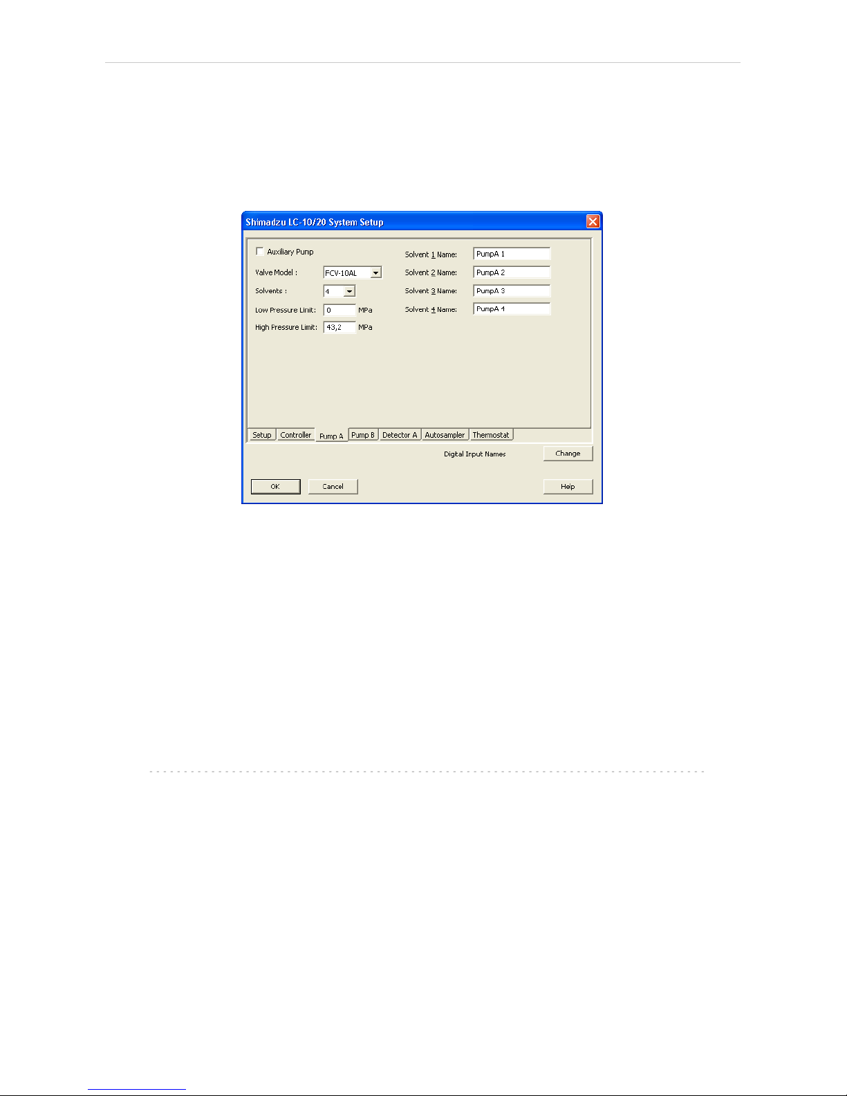
Fig 9: Shimadzu LC-10/20 System Setup - Pump
Auxiliary Pump
Check for the pump to become auxiliary pump (not part of the Gradient
Table). If there are more pumps added in the configuration and the first
one is set either as low- pressure gradient or binary pump, the other
pumps are automatically set as Auxiliary pumps.
Valve Model
Select the valve model installed in your pump. This selection influences
the number of solvents available.
Solvents
Select the number of solvents to be used.
Note: Only the first pump configured as a gradient pump allows to set the
number of solvents in the Low- pressure gradient. Available options
depend on the Valve Model configured.
Solvent 1 (..4) Name
Change names for the particular solvent.
Low Pressure Limit
Lower pressure limit. Number entered will be sent to the pump and
checked by the pump firmware.
- 17 -
Page 24

Shimadzu LC-10/20 System 4 Using the control module
High Pressure Limit
Upper pressure limit. Number entered will be sent to the pump and
checked by the pump firmware.
Note: Exceeding of High Pressure Limit or Low Pressure Limit defined here will
cause a system error, requiring the closure and reopening of the given
Instrument.
- 18 -
Page 25

4 Using the control module Clarity Controls
4.1.2 Method Setup - LC Gradient
The Method Setup - LC Gradient dialog serves for setting up the LC
instrument method.
Fig 10: Method Setup - LC Gradient
Gradient Table
A table for setting the composition of the mobile phase and the overall
flow rate as a function of time. Operation is analogous to that of
spreadsheets (Excel, Quatro Pro, etc.). To prepare the cell to receive
values, click it by the left mouse button; the cell will highlight by dots. A cell
that fails to highlight is not available for editing.
Time [min.]
Sets the time at which the ratio of flow rates and the overall flow rate
correspond to the values entered in the corresponding row. (These
values vary continuously from one time to the next in a manner
ensuring that the conditions specified in the next row are satisfied).
XXX1 (..4) [%]
Represents the percentage of a component. The designation XXX1-4
is in fact replaced by the name of the component (items Solvent 1 - 4
in the Gradient Options dialog). Should you enter a component value
such that the sum of all values exceeds 100 %, the percentage in the
last column is automatically adjusted; if the percentage of the last
compound is already zero, the value of the currently entered
component is adjusted instead. The flow rate of a compound is
calculated by multiplying the overall flow rate (indicated in the Flow
column) by the corresponding percentage divided by 100.
- 19 -
Page 26

Shimadzu LC-10/20 System 4 Using the control module
Flow [ml/min]
Indicates the overall flow rate through the column. The entered value
applies to the time specified in the corresponding row.
Note: The values of the Flow for the Shimadzu LC-10/20 pumps vary in certain
range according to the type of the pump. Check the device manual for
valid Flow ranges for your pump.
Graph
The graph depicts the percentage of components as a function of time
together with the overall flow rate. Data are taken over from the Gradient
Table. Changes effected in this table are immediately reflected in the
graph. Legend in the header of the graph indicates the assignment of
colors to individual components. The assignment is fixed and individual
components are displayed in the graph from bottom to top. The flow rate is
displayed as a black line.
The graph has two vertical axes: the axis on the left refers to the mixing
ratio, the one on the right to the overall flow rate.
Parameters
Standby Flow
Sets the overall flow rate through the column in the STANDBY state
reached after the last row of the table has been performed and the
time period defined in the Time to Standby field has passed. The
duration of this state is defined by the Standby Time item. The ratio of
individual components in the respective STANDBY and IDLE states is
given by the first row of the Gradient Table (the Initial row).
Time to Standby [min]
Indicates the time during which the flow rate and mobile phase
composition changes continuously between the last values entered in
the table and the values defined by Standby Flow field and the Initial
row mobile phase composition.
This time is included in the analysis time (the Instrument is in the
CONTROL state). In case when the Time to Standby is zero, there is
step change from flow and components percentage specified on the
last row of gradient table to that specified for STANDBY state.
Standby Time [min]
The time during which the flow rate is maintained at Standby Flow .
This time is included in the analysis time (the Instrument is in the
CONTROL state).
Idle State
An item specifying the overall flow rate through the column outside the
instrument method. The following options are possible:
Pump Off
The flow rates of all components are zero.
- 20 -
Page 27

4 Using the control module Clarity Controls
Caution: Be careful as this setting may damage the column in some cases.
Initial
The flow rate is defined by the first row of the Gradient Table (the
Initial row).
Standby
The flow rate is the same as in the STANDBY mode and, accordingly,
corresponds to the value entered in Standby Flow field.
Initial - Standby
The flow is defined by the first row of the gradient table (the Initial row)
after the method is sent, or by the value entered in the Standby Flow
field after the method finishes.
The IDLE state comes into effect each time an Instrument is opened, at the
end or after abortion of an analysis by the Abort command, and is also
maintained after the Clarity program is shut down.
The mixing ratio of individual components in both the IDLE and STANDBY
states is given by the first row of the Gradient Table (the Initial row).
Note: There is a step change in the flow and components percentage from the
values specified for the STANDBY state to those specified for the IDLE
state if the Idle State field is not set to Standby.
4.1.2.1 Gradient Options
Invoke the Options… button in the Method Setup - LC Gradient dialog to
open the Gradient Options dialog. This dialog allows to set the custom
name for particular solvents, to switch whether they are used or not in the
gradient and to set the warning levels for pressure to prevent the damage
to hardware.
The abovementioned pressure limits are checked in the software.
Pressure check for low pressure limit doesn’t start immediately after pump
is started, but with few minutes delay. During this delay the pressure in
chromatographic system can stabilize.
In addition to those limits, a pressure limits are set in the Shimadzu LC-
10/20 System Setup - Pump dialog. Those limits are checked in the pump
firmware. As they will cause a system error, they should be set outside the
limits defined here in the Gradient Options dialog.
Fig 11: Gradient Options
- 21 -
Page 28

Shimadzu LC-10/20 System 4 Using the control module
Min. Pressure
Sets the minimum pressure for the given pump. When pressure drops to
the set value, the pump will shut down. This prevents the solvent leakage.
Max. Pressure
Sets the maximum pressure for the given pump. When pressure reaches
the set value, all pumps on the Instrument will shut down. This serves to
prevent the damage to the pump when the column is blocked.
Note: Min. Pressure and Max. Pressure for the Shimadzu LC- 10/20 pumps
vary in certain range according to the type of the pump and valves used.
Check the device manual for valid values for your pump.
Solvent 1 (..4)
It is possible to enable/disable particular solvent, as well as to set custom
name to it.
- 22 -
Page 29

4 Using the control module Clarity Controls
4.1.3 Method Setup - LC
If the only pump was set to Auxiliary mode in the Shimadzu LC-10/20
System Setup - Pump dialog, the LC tab will appear instead of the LC
Gradient tab. The LC tab will also appear if the second pump is set to
Auxiliary mode (showing only the Auxiliary Pump sub- tab) or when
primary pump is configured with valve and only one solvent in the
Shimadzu LC-10/20 System Setup - Pump dialog (showing only the LC
Valve sub-tab).
In case that several pumps with the LC tab available are configured on the
same Clarity Instrument, it is possible to switch between them using the
Select LC menu on the top of the LC tab.
From LC
Acquires the status of the auxiliary pump from the controller.
LC Status
Invokes the hardware configuration dialog listing the settings of the
Shimadzu LC-10/20 System. The upper part shows the settings of the
controller, the lower part the settings of other modules.
Fig 12: Method Setup - LC - Hardware Configuration
- 23 -
Page 30

Shimadzu LC-10/20 System 4 Using the control module
Auxiliary Pump tab
Fig 13: Method Setup - LC - Auxiliary Pump
Initial Flow
Sets the initial flow of the auxiliary pump.
Solvent B Concentration
Allows to set the percentage of the second solvent in the mixture created
by auxiliary binary pump. This field is only present for the LC-20AB pump
(which is binary) in the auxiliary pump mode.
Low Pressure Limit
Sets the minimum pressure for the given auxiliary pump. When pressure
reaches the set value, the pump will shut down. This prevents the solvent
leakage.
High Pressure Limit
Sets the maximum pressure for the given auxiliary pump. When pressure
reaches the set value, the pump will shut down. This serves to prevent the
damage to the pump when the column is blocked.
Time Program
This table sets the flow changes for the auxiliary pump based on the
analysis time. Insert the desired time in minutes into the Time column, set
the Flow event in the Event column and the desired flow value into the
Parameter column.
- 24 -
Page 31

4 Using the control module Clarity Controls
LC Valve tab
Tab listing the Valve Position table. Each row defines the change of the
valve position in given time. These settings can be later printed as a part
of the report.
Note: The valves set on particular pumps may not be governed from the Method
Setup - Event Table dialog, only from the Time Table on the Method
Setup - LC - LC Valve tab.
Fig 14: Method Setup - LC - LC Valve
- 25 -
Page 32

Shimadzu LC-10/20 System 4 Using the control module
4.1.4 Method Setup - Advanced
Fig 15: Method Setup - Advanced
Shimadzu LC- 10/20 System provides the pump flow and pressure
auxiliary signals for use in Clarity. To save the auxiliary signals into each
chromatogram measured according to the given method, check the
particular checkbox in the lower section of the Method Setup - Advanced
dialog.
- 26 -
Page 33

4 Using the control module Clarity Controls
4.1.5 Device Monitor
The pump status dialog can be invoked by the Monitor - Device Monitor
command from the Instrument window or using the LC Monitor icon.
Device Monitor - LC Monitor
It displays the actual flows of particular solvents, as well as the total flow,
the total pressure and the analysis time.
Fig 16: LC Monitor
Stop Flow
The pumps can be stopped from this window using the Stop Flow button.
This action will stop the pump only, the analysis run will continue and
must be stopped or aborted from the Data Acquisition window or Single
Analysis dialog.
Purge
The pumps may be purged by pressing this button. Set the desired total
flow and solvent ratios in the opened Set Flow dialog.
Fig 17: Set Flow
Resume Idle
Returns the pumps to IDLE state as defined in the appropriate field on the
LC Gradient tab of the Method Setup dialog.
- 27 -
Page 34

Shimadzu LC-10/20 System 4 Using the control module
Device Monitor - Auxiliary Pump
Each Auxiliary pump has its own device monitor displaying the actual flow
and pressure on the device.
Fig 18: Device Monitor - Auxiliary pump
- 28 -
Page 35

4 Using the control module Clarity Controls
4.1.6 Report Setup
All of the pump settings accessible on the Method Setup - LC Gradient tab
and in the Gradient Options dialog are reported, if the pump is configured
as the part of the gradient. To do so, the Instrument Control parameter on
the Method tab of the Report Setup dialog must be checked.
Fig 19: Report - pump part of the gradient
If the pump is set as an Auxiliary pump, thus excluded of the Gradient
Table, the values set on the of the Method Setup - LC tab are reported,
including the Time Table. To do so, the Instrument Control parameter on
the Method tab of the Report Setup dialog must be checked.
Fig 20: Report - Auxiliary pump
- 29 -
Page 36

Shimadzu LC-10/20 System 4 Using the control module
4.2 Detector
4.2.1 Shimadzu LC-10/20 System Setup - Detector
The Shimadzu LC-10/20 System Setup - Detector tab for SPD detectors
and RF detectors looks the same, although some items may be missing
depending on the type of the detector.
Fig 21: Shimadzu LC-10/20 Detector setup
Base Period
Specifies the base rate of the detector signal acquisition. The value set
here is also limiting the available range of values for the Sampling Rate
as set in the Method Setup - Acquisition dialog - the lower Base Period is,
the higher can the Sampling Rate be. The possible values are influenced
by the checking/unchecking of the Dual Mode item.
Dual Mode
Check to perform the data acquisition on two wavelengths.
Use Recycle Valve
Defines whether the solvent recycling valve is used during the acquisition.
Signal 1 (2) Name
Sets the name of the given detector.
- 30 -
Page 37

4 Using the control module Clarity Controls
RID-10A Detector Setup
The Shimadzu LC- 10/20 System Setup - Detector tab for the RID-10A
detector differs somewhat from the classical one. All options are the same
except for the Large Scale Preparative Option Installed.
Fig 22: Shimadzu LC-10/20 Detector setup - RID-10A
Large Scale Preparative Option Installed
Defines whether the optional Large Scale Preparative Option is installed
in the RID-10A detector.
- 31 -
Page 38

Shimadzu LC-10/20 System 4 Using the control module
4.2.2 Method Setup - Acquisition - Detector
In case of greater number of detectors configured on one Instrument, it is
possible to switch to the desired detector by selecting it in the Select
Detector menu on the upper part of the Method Setup - Acquisition
window.
The chapter describes the SPD detectors, other detector types are
described later in the manual.
Fig 23: Method Setup - Acquisition - Detector
Wavelength Ch.1
Defines the initial wavelength of the first channel.
Wavelength Ch.2
Defines the initial wavelength of the second channel, available only in the
Dual Mode . Any changes made on the tab of one channel will be also
changed on the other channel of the Dual Mode detector.
Lamp
Sets the lamp used at the beginning of the analysis. Available options are
(based on the type of the detector): Off, D2, W, D2+W
Polarity
Selects the initial polarity of the detector.
Response
Defines the level of the digital noise filter. The higher the number set, the
lower the noise level is. On the other hand, some peaks may not be
detected.
- 32 -
Page 39

4 Using the control module Clarity Controls
Sampling Rate
Sets the sampling rate of the detector. The available detector sample rates
are dependent on the Base Period settings on the Shimadzu LC-10/20
System Setup - Detector tab - by using the shortest Base Period of 20 ms,
the Sampling Rate can be set up to 50 Hz. Please note that in dual mode
the Base Period is limited to 100 ms and maximum Sampling Rate to 10
Hz.
Cell Temperature
Sets the cell temperature of the given detector. The Value range is
between 9 and 50 °C.
Check Cell Temperature
If checked, doesn't allow the Instrument to become READY until the
temperature is not close to the temperature set in the Cell
Temperature field (with the tolerance of 1,5 °C).
- 33 -
Page 40

Shimadzu LC-10/20 System 4 Using the control module
4.2.2.1 Method Setup - Acquisition - RF Detector
This sub-tab replaces the Detector sub- tab when one of the configured
RF-10A and RF-10Axl detectors is selected in the Select Detector field.
Fig 24: Method Setup - Acquisition - RF Detector
Excitation Wavelength
Sets the excitation wavelength. The possible values are in the range 200
to 900 nm.
Emission Wavelength
Sets the emission wavelength. The possible values are in the range 200
to 900 nm.
Lamp
Sets whether the lamp should be activated prior to the analysis.
Gain
Selects the detector gain amplification value. Possible options are x1, x4
and x16.
Sensitivity
Sets the detector sensitivity by adjusting the voltage on the
photomultiplier.
Response
Defines the detector signal response. Possible values vary for the RF-10A
and RF-10Axl detector.
Sampling Rate
Sets the sampling rate of the detector. The available detector sample rates
are dependent on the Base Period settings on the Shimadzu LC-10/20
- 34 -
Page 41

4 Using the control module Clarity Controls
System Setup - Detector tab - by using the shortest Base Period of 20 ms,
the Sampling Rate can be set up to 50 Hz. Please note that in dual mode
the Base Period is limited to 100 ms and maximum Sampling Rate to 10
Hz.
- 35 -
Page 42

Shimadzu LC-10/20 System 4 Using the control module
4.2.2.2 Method Setup - Acquisition - RID Detector
This sub-tab replaces the Detector sub-tab when the configured RID-10A
detector is selected in the Select Detector field.
Fig 25: Method Setup - Acquisition - RID Detector
Mode
This field specifies the operating mode of the detector. The contents of the
field depend on the state of the Large Scale Preparative Option Installed
checkbox in the Shimadzu LC-10/20 System Setup - Detector dialog for
RID detector. If the checkbox is checked, the Large Scale Preparative text
is the only option to be selected in the field. If the checkbox is left
unchecked, the Analytical and Semi-preparative options are available.
Polarity
Sets whether the increasing refraction value will be counted as more
Positive or more Negative voltage signal.
Response
Defines the level of the digital noise filter. The higher the number set, the
lower the noise level is. On the other hand, some peaks may not be
detected.
Sampling Rate
Sets the sampling rate of the detector. The available detector sample rates
are dependent on the Base Period settings on the Shimadzu LC-10/20
System Setup - Detector tab - by using the shortest Base Period of 20 ms,
the Sampling Rate can be set up to 50 Hz. Please note that in dual mode
the Base Period is limited to 100 ms and maximum Sampling Rate to 10
Hz.
- 36 -
Page 43

4 Using the control module Clarity Controls
Cell Temperature
Sets the temperature of the detector cell.
Check Cell Temperature
When checked, the Instrument will not be ready until the actual
temperature will reach the set value (with the 1.5 °C tolerance). While
the checkbox is unchecked, no temperature verification will be
performed.
- 37 -
Page 44

Shimadzu LC-10/20 System 4 Using the control module
4.2.3 Method Setup - Acquisition - Time Program
This sub-tab allows to reset the detector parameters defined on other tabs
based on the analysis time. Note that the options listed in the Event
column depend on the type of the detector (not all events listed under the
picture are accessible).
Fig 26: Method Setup - Acquisition - Time Program
Time Table
The initial analysis settings defined on the Detector sub- tab can be
changed during the analysis by events programmed in the Time Table.
Possible events are:
Zero - Set the current absorbance value to zero.
Mark - Marks recorder output.
Polarity - Change the polarity of the signal.
Recorder Range - Change the range of the output signal.
Response - Change the settings of the digital noise filter.
Sensitivity - Changes the sensitivity parameter. Only available for RF
detectors.
Lamp - Select the lamp type to be used.
Wavelength - Set the wavelength of the chosen detector.
Cell Temperature - Set the desired cell temperature. Allowed values are in
range 9 - 50 °C, 0 means that the cell temperature control is off.
Flow - Switches the flow in the detector reference cell On and Off. Only
available for RID detectors. The function of the command is the same as
the function of the Flow Off/On button in the Device Monitor window.
Balance - Sends the Balance command to the detector. Only available for
RID detectors. The function of the command is the same as the function of
the Balance button in the Device Monitor window.
- 38 -
Page 45

4 Using the control module Clarity Controls
Gain - Change the current Gain parameter. Only available for RF
detectors.
Excitation Wavelength - Change the current Excitation Wavelength
parameter. Only available for RF detectors.
Emission Wavelength - Change the current Emission Wavelength
parameter. Only available for RF detectors.
- 39 -
Page 46

Shimadzu LC-10/20 System 4 Using the control module
4.2.4 Method Setup - Acquisition - Analog Output
Fig 27: Method Setup - Acquisition - Analog Output
Auxiliary Range
Sets output range of integrator terminals.
Caution: Auxiliary range will affect the acquired signal. For RID-10A and RID-20A
detectors use 0.25 mRIU/V to get correct signal values
Recorder Range
Sets the range of the recorder.
Synchronize with Auxiliary Range
Synchronizes the Recorder Range with the Auxiliary Range value.
Recorder Mode
Sets the output mode of the recorder terminals.
Ratio Range
Sets the range of the signal ratio calculation.
Ratio Threshold
Sets the threshold of the signal ration calculation.
- 40 -
Page 47

4 Using the control module Clarity Controls
4.2.5 Device Monitor
The Device Monitor window can be invoked by the Monitor - Device
Monitor command from the Instrument window or using the Device
Monitor icon. It displays the actual wavelength and the lamp used, the
cell temperature (if configured) and allows to perform the Autozero action
and switch the signal on outside of the analysis.
Fig 28: Device Monitor - Detector
It is possible to control the detector operation during the analysis in the
Device Monitor window.
Auto Zero
Sets the response of the detector to 0.
Wavelength
Displays the wavelength set in the method.
Lamp
Displays the type of lamp set in the detector.
Cell Temp.
Shows the actual temperature on the detector cell.
Check Signal On
Turns the detector signal monitoring on and off. Active only when analysis
is not running.
Note: This type of detectors is giving data only during analysis. Pressing this
button starts a "dummy" analysis run (all data discarded) that allows to
check the detector signal before the actual analysis. It should be turned
OFF before starting the analysis by external contact.
Caution: The Check Signal On function can not be activated when a Purge was
used to set the flow and composition manually from the Device Monitor .
You need to use the Resume Idle function from the LC Device Monitor
first.
- 41 -
Page 48

Shimadzu LC-10/20 System 4 Using the control module
Device Monitor - RID Detector
The RID detectors has slightly different Device Monitor window with other
options on the monitor pane. Only new items are described:
Fig 29: Device Monitor - RID Detector
Balance
When invoked, sends the Balance command to the detector. For the
description of the command see Shimadzu RID- 10A detector
documentation.
Flow Off/On
When invoked, the flow in the reference detector cell is switched off and
the button changes to the Flow On. If invoked again, the flow will be
renewed and the button returns to the Flow Off state.
Device Monitor - RF Detector
The RF detectors has slightly different Device Monitor window with other
options on the monitor pane. Only new items are described:
Fig 30: Device Monitor - RF Detector
Ex. Wavelength
Displays the currently set Excitation Wavelength . This value may be
changed in the Time Table on the Method Setup - Acquisition - Time
Program tab of the RF detectors.
Em. Wavelength
Displays the currently set Emission Wavelength . This value may be
changed in the Time Table on the Method Setup - Acquisition - Time
Program tab of the RF detectors.
- 42 -
Page 49

4 Using the control module Clarity Controls
4.2.6 Report Setup
All detector settings accessible on the Method Setup - Acquisition tab
(including sub-tabs) are reported if the Instrument Control parameter on
the Method tab of the Report Setup dialog is checked. For each detector
set in the Shimadyu LC-10/20 System Setup dialog, a specific section of
the report will be printed.
Fig 31: Report Setup
Two groups of parametres are then printed, one common to all channels
of a given detector, the other specific to particular channels. The first
section also includes the Time Table from the Method Setup - Acquisition
- Time Program tab. The other part of the report is the detector specific
parametres. When the Dual Mode is off, only one set of parametres will be
printed in this section, while in the Dual Mode, two sets will be present,
one for each channel.
Report Setup - RID Detector
Fig 32: Report Setup - RID Detector
- 43 -
Page 50

Shimadzu LC-10/20 System 4 Using the control module
The report setup of the RID- 10A detector differs only in the items
displayed, it is the same in all other respects.
Report Setup - RF Detector
Fig 33: Report Setup - RF Detector
The report setup of the RF detectors differ only in the items displayed, it is
the same in all other respects.
- 44 -
Page 51

4 Using the control module Clarity Controls
4.3 Autosampler
The autosamplers used with the Shimadzu LC-10/20 System allow for
automated injection of samples. This can only be performed from the
Sequence window, not from the Single Analysis dialog (where it is
impossible to specify from which position the injection will be performed).
4.3.1 Shimadzu LC-10/20 System Setup - Autosampler
Some options may be missing or shaded depending on the type of the
autosampler installed.
Fig 34: Shimadzu LC-10/20 System Setup - Autosampler
Name
Sets the name of the autosampler.
Sample Loop Size
Defines the volume of the injector loop. Some parameters are predefined,
but any whole number in certain range can be entered. The range
depends on the type of the autosampler.
Injection Triggered By External Device
Sets whether the injection will be performed only after the external start
contact on the controller is closed.
Skip Missing Vial
Defines whether the missing vial in the sequence measurement should be
skipped. Otherwise, the sequence would be stopped when encountering
the missing vial.
Sample Cooler Installed
Defines whether the tray cooler is installed.
- 45 -
Page 52

Shimadzu LC-10/20 System 4 Using the control module
MTP Sample Order
Defines the numbering of wells in the plate when the MTP Tray is used. If
other trays are used, this option is ignored. Possible parameters are
Horizontal or Vertical.
Rack Changer Installed
Enables the rack changer control in case a rack changer is installed.
Rinse Pump Installed
Enables the control of the rinse pump (if it is installed).
Supports Pretreatment
Enables the display of the Pretreatment sub-tab of the Method Setup - AS
dialog. For this option to function, it is necessary to have the Pretreatment
option installed in the hardware.
- 46 -
Page 53

4 Using the control module Clarity Controls
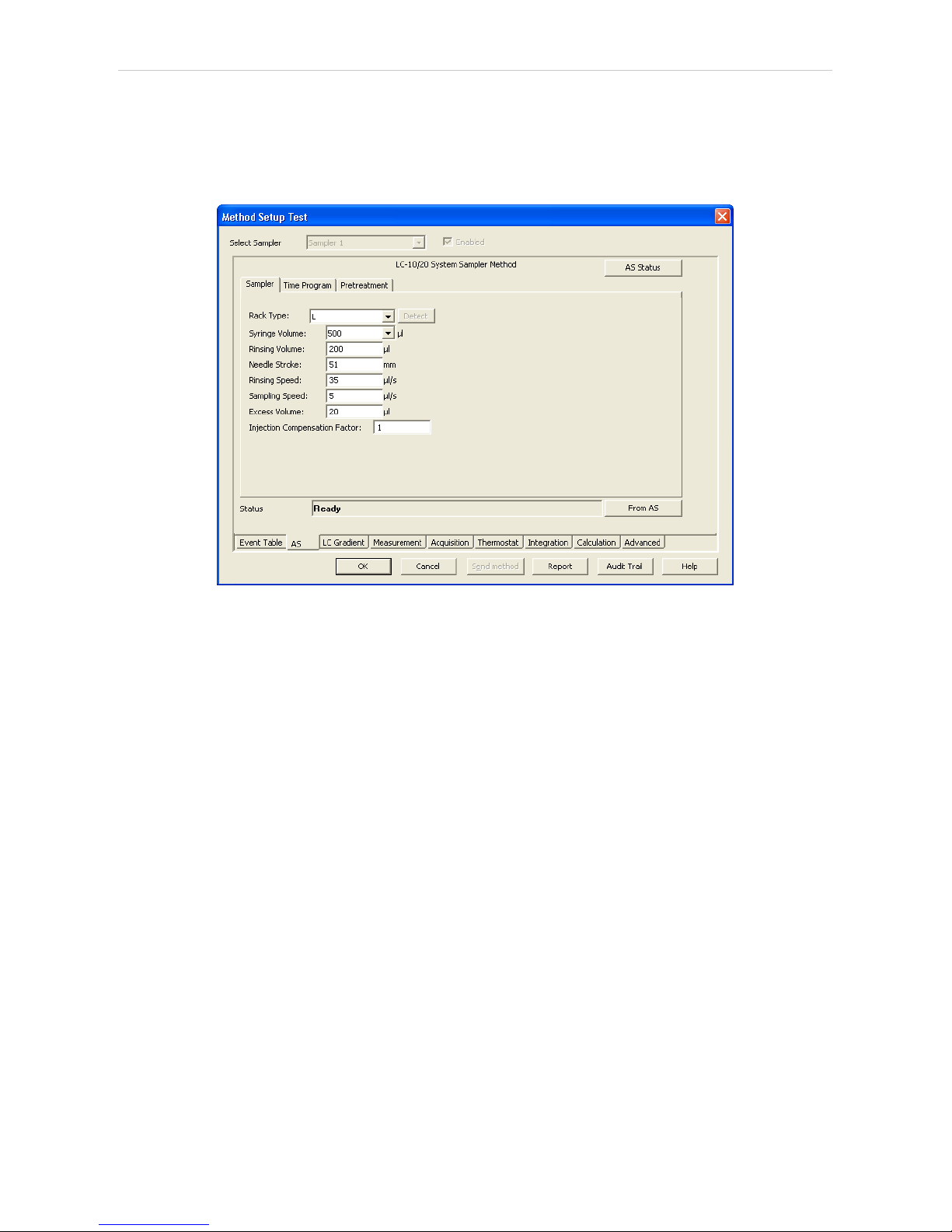
4.3.2 Method Setup - AS - Sampler
Fig 35: Method Setup - AS - Sampler
Rack Type
Defines the sample rack type. For some trays, it is also necessary to
choose the correct Tray Type (Single or Dual).
Detect
Auto detects the Rack Type and sets the Needle Stroke parameter.
Note: Vialnumber mapping on various types of trays can be found in the chapter
"Vial Plate Numbers" on pg 71.
Rinsing Volume
Sets the volume of the solvent used for rinsing the flow lines.
Needle Stroke
Sets the depth of the needle penetration into the vial. The Needle Stroke
is defined by the Rack Type installed.
Rinsing Speed
Sets the solvent discharge speed when rinsing.
Sampling Speed
Sets the speed of the sample aspiration into the syringe.
Purge Time
Sets the duration of the Purge operation.
Rinse Dip Time
Sets the time for which the needle tip will remain immersed in the rinsing
solvent.
- 47 -
Page 54

Shimadzu LC-10/20 System 4 Using the control module
Rinse Mode
Sets the time when the rinsing will be performed. Available options are No
Rinsing , Before Aspiration , After Aspiration and Before and After
Aspiration.
Cooler Temperature
Enables the cooling of the autosampler. This option is available only after
the Sample Cooler Installed option was checked in the Shimadzu LC-
10/20 System Setup - Autosampler dialog. The field than allows to set the
desired temperature.
Check Cooler Temperature
If checked, doesn't allow the Instrument to become READY until the
temperature is not close to the temperature set in the Cooler
Temperature field (with the tolerance of 1,5 °C).
Control Vial Needle Stroke
Sets the needle depth used when aspirating from the Control Rack (used
with the SIL-20 samplers).
Rinse Pump
Section enabled by checking the Rinse Pump Installed option in the
Shimadzu LC-10/20 System Setup - Autosampler dialog.
Rinse Method
Sets the method for the Rinse Pump. Port Only, Pump Only, Pump
Then Port, Port Then Pump, Pump And Port Between Analyses and
Auxiliary 1 (2) methods are available.
Rinse Time
Sets the length of the rinse. Possible values are integers in the range
1 - 9.
Rack Changer
Section enabled by checking the Rack Changer Installed option in the
Shimadzu LC-10/20 System Setup - Autosampler dialog.
Rack Type D..A
Sets the type of the rack for each position in the rack changer.
Needle Stroke D..A
Sets the needle stroke depth (in mm) for each particular rack in the
rack changer.
Note: When the Rack Changer tray type has been selected, the common
Needle Stroke parameter is not used and thus is disabled. Moreover, do
not use values less than 20 for rack types 4, 5, 14 or 15.
- 48 -
Page 55

4 Using the control module Clarity Controls
4.3.2.1 Method Setup - AS - Sampler (SIL-10Axl)
This sub-tab replaces the Sampler sub-tab when the SIL-10Axl sampler is
configured on the Instrument. The majority of items in the dialog is the
same, the differing items are described below:
Fig 36: Method Setup - AS - Sampler (SIL-10Axl)
Caution: Due to the error in the MIMIC Libraries, SIL- 10AXL sampler does not
support the non-default rack types. Only S rack type should be used while
operating this sampler from Clarity.
Check Cooler Temperature
While checked, the temperature set in the Cooler Temperature field is
validated against the real cooler temperature. When both values don't
match, the Instrument will not become ready.
Injection Compensation Factor
The value that is used to compensate the actual volume of different
injectors. The specified Injection volume is multiplied by the Injection
Compensation Factor value to produce the real injection volume. Possible
values are 1.00 - 1.30, although usually the value 1.00 is used.
- 49 -
Page 56
Shimadzu LC-10/20 System 4 Using the control module
4.3.2.2 Method Setup - AS - Sampler (SIL-10AF)
This sub-tab replaces the Sampler sub-tab when the SIL-10AF sampler is
configured on the Instrument. The majority of items in the dialog is the
same, the differing items are described below:
Fig 37: Method Setup - AS - Sampler (SIL-10AF)
Excess Volume
Allows to set the excess volume of the sample drawn into the syringe
during each injection. This portion of the sample is not injected, but serves
for better precision of the injection. Allowed values in the Excess Volume
field are between 10 and 100 μl.
Injection Compensation Factor
The value that is used to compensate the actual volume of different
injectors. The specified Injection volume is multiplied by the Injection
Compensation Factor value to produce the real injection volume. Possible
values are 1.00 - 1.30, although usually the value 1.00 is used.
- 50 -
Page 57

4 Using the control module Clarity Controls
4.3.3 Method Setup - AS - Time Program
Fig 38: Method Setup - AS - Time Program
Time Table
It is possible to set events to be performed during the analysis run based
on the analysis time, namely the Inject , Rinse and Start Pretreatment
actions.
Note: The time needed to perform the Rinse operation is longer than 1 minute,
for exact duration it is necessary to test it in the given configuration.
- 51 -
Page 58

Shimadzu LC-10/20 System 4 Using the control module
4.3.4 Method Setup - AS - Pretreatment
The logic for all calculations of pretreatment vials goes as follows: The vial
specified in the Sequence window for the injection (called the Sample
vial , SV ) needs to be empty when performing pretreatment. The actual
sample is in the Source Vial (specified on the Method Setup - AS -
Pretreatment tab), while the diluent is placed in the Diluent Vial and
reagents are placed in Reagent Vials 1..3.
When using the Auto calculation of the Source Vial, the source vials are
found on the second half of the vial tray; the first half of the tray is reserved
for the empty vials used for mixing (diluting). These vials are specified in
the Sequence window and from these vials the injection is performed.
Note: In case of racks with odd number of vials, the middle vial cannot be used
as Sample Vial with pretreatment operation as it would have no
corresponding Source Vial.
Fig 39: Method Setup - AS - Pretreatment (Dilution)
Mode
Selects the pretreatment mode. There are 3 types of pretreatment
available:
Standard - Standard type of autosampler operation with no special
pretreatment. No other parameter fields are available on the Pretreatment
tab. This mode is also used when the Pretreatment tab is unavailable.
Dilution - Sample will be diluted before the injection.
Reagent - Sample will be mixed with the reagent and then injected.
Inner Needle Wash - Sampler inner needle will be washed prior and/or
after the injection.
- 52 -
Page 59

4 Using the control module Clarity Controls
Note: The Advanced pretreatment mode is not currently supported by Clarity.
The set of other parameters available differ according to the Mode
selected.
Dilution
Source Vial
Specifies the source vial for the original sample (before dilution).
Note: The vial used for dilution and injection is specified in the Sequence
window.
Diluent Vial
Specifies the vial from which the diluent (solvent) will be taken.
Total Volume
Specifies the final volume of the diluted sample without the respect to the
volume contraction.
Dilution Factor
Specifies the factor for the dilution. For example, the factor 5 means that
the resulting diluted sample will consist of 1/5 of pure sample and 4/5 of
diluent.
Mixing Count
Specifies the number of mixing cycles the dilution will consist of (range 1 10 cycles).
Mixing Volume
Specifies the volume to be aspirated and flushed back in every mixing
step. This volume must be lower than the Total Volume.
Bubbling
When checked, a bubble is aspirated during the mixing cycle in addition
to the specified volume. The bubble is dispensed into the vial during
mixing.
Wait Time
Sets the time interval from the last mixing cycle to the injection. Possible
values are 0.1 - 120 minutes.
- 53 -
Page 60

Shimadzu LC-10/20 System 4 Using the control module
Reagent
Fig 40: Method Setup - AS - Pretreatment (Reagent)
Part of the fields (namely Mixing Count , Mixing Volume , Bubbling and
Wait Time) in the Reagent mode has the same meaning as in the Dilution
mode. Different fields are described lower:
Source Vial
Specifies the source vial for the original sample (before reaction). The
automatic calculation uses the same rules as in the Dilution mode.
Reagent Vial 1..3
Specifies vials used for particular reagents. It is possible to select the Not
Used option.
Volume
Specifies the volume of the sample and each reagent used.
- 54 -
Page 61

4 Using the control module Clarity Controls
Inner Needle Wash
Fig 41: Method Setup - AS - Pretreatment (Inner Needle Wash)
Pre-Rinse
Sets the rinsing prior to the injection (which is not recommended). The
same options as for the Rinse operation (see below) apply.
Rinse 1[2]
Sets the first (second) rinse solvent. It is possible to select from the Not
Used, Rinse 1, Rinse 2 and Mobile Phase options.
Replenish
Select whether or not to replenish the Inner Needle by the mobile phase
after rinsing. If any Pre- Rinse or Rinse step is used, the only option is
Mobile Phase, otherwise Not Used option is also available.
Wait Time
Sets the time for which the injection loop will be switched into the flow
path to wash away the sample from there. After elapsing of this time
period the Rinse 1 and Rinse 2 operations will be performed. Available
time span for this field is 0.1 - 120 minutes.
- 55 -
Page 62

Shimadzu LC-10/20 System 4 Using the control module
4.3.5 Device Monitor - Shimadzu LC-10/20 System
The Device Monitor window can be invoked by the Monitor - Device
Monitor command from the Instrument window or using the Device
Monitor icon. It displays the actual cooler temperature (if configured)
and allows to perform the Purge and Rinse actions.
Fig 42: Device Monitor - Autosampler
Purge
Runs the Purge operation according to the settings in the Method Setup -
AS - Sampler dialog.
Rinse
Rinses the syringe according to the settings in the Method Setup - AS -
Sampler dialog.
Cooler Temp.
Displays the temperature of the cooler. Only available when the
autosampler is equipped with the sample cooling unit and the Sample
Cooler Installed checkbox is checked in the Shimadzu LC-10/20 System
Setup - Autosampler dialog.
- 56 -
Page 63

4 Using the control module Clarity Controls
4.3.6 Report Setup
The autosampler settings accessible from the Method Setup - AS tab and
Shimadzu LC- 10/20 System Setup - Autosampler dialog may also be
included in the report. To do so, the Injection Control parameter on the
Method tab of the Report Setup dialog must be checked.
Fig 43: Report Setup - Autosampler
The first part of the parametres is taken from the Shimadzu LC- 10/20
System Setup - Autosampler dialog settings, the second part contains
parametres set on the Method Setup - AS tab (including the Time Table).
- 57 -
Page 64

Shimadzu LC-10/20 System 4 Using the control module
4.4 PDA
4.4.1 Shimadzu LC-10/20 System Setup - PDA Detector
Caution: It is necessary to switch the PDA detector on before switching on the PC.
Fig 44: Shimadzu LC-10/20 System Setup - PDA Detector
Name
Sets the name of the PDA Detector.
Host ID
Uniquely identifies the SCSI adapter board. This number is assigned by
the operation system and can be found in the Device Manager. The
default value is 0. See Shimadzu SPD-M10Avp manual for more details.
Device ID
Number of the PDA Detector unit (set on the back of the unit). The default
value is 4. See Shimadzu SPD-M10Avp manual for more details.
Note: When using the SPD-M20A device, the IP Address and Port commands
are displayed instead of Host ID and Device ID . These two specify the
parameters of the connection through LAN.
D/A Board Installed
Sets whether the optional D/A output converter (not autodetected) is
installed in the PDA unit.
Triggered by External Device
Check if the PDA should start acquisition based on the external signal (by
wire from the back of the device).
Note: In the standard operation mode, the PDA detector is started by the
controller (this checkbox should be unchecked).
- 58 -
Page 65

4 Using the control module Clarity Controls
Signal 1 (..4) Name
Defines the names of the particular detector signals.
- 59 -
Page 66

Shimadzu LC-10/20 System 4 Using the control module
4.4.2 Method Setup - PDA
Fig 45: Method Setup - PDA
Start Wavelength
Defines the lowest value of the wavelength to be used for the acquisition
of spectra. This value also influences the lowest possible value of the
Wavelength parameter on the Method Setup - Acquisition tab for the
single- wavelength PDA detector signals. The value must be in range
<190, 799> and lower than the End Wavelength value.
End Wavelength
Defines the highest value of the wavelength to be used for the acquisition
of spectra. This value also influences the highest possible value of the
Wavelength parameter on the Method Setup - Acquisition tab for the
single- wavelength PDA detector signals. The value must be in range
<191, 800> and greater than the Start Wavelength value.
Wave Step
Sets the wavelength step for the PDA spectra gathering. The lowest
possible value is 1 nm.
Lamp
Defines the lamp type that will be used in the measurement. Possible
options are Off, D2, W and D2+W.
Sampling Rate
Defines the sampling rate of the PDA detector, set in the Hz.
Time Constant
Sets the amount of time from which will the raw spectra be averaged to get
one reported spectrum. The value should be set so that it is longer than it
- 60 -
Page 67

4 Using the control module Clarity Controls
takes to gather one spectrum (based on the Sampling Rate parameter).
Slit Width
Defines the wavelength accuracy provided by the hardware.
Cell Temperature
Sets the temperature of the detector cell.
Check Cell Temperature
When checked, the Instrument will not be ready until the actual
temperature will reach the set value (with the 1.5 °C tolerance). While the
checkbox is unchecked, no temperature verification will be performed.
- 61 -
Page 68

Shimadzu LC-10/20 System 4 Using the control module
4.4.3 Method Setup - Acquisition
Fig 46: Method Setup - Acquisition - PDA Signal
Wavelength
Sets the wavelength of the desired analog signal. This value must lie in
the range set by the Start Wavelength and End Wavelength parameters
defined on the Method Setup - PDA tab.
Bandwidth
Sets how "wide" will the wavelength window be for the purpose of the
analog signal creation. This signal is created by calculation from several
wavelengths, not by hardware settings.
Polarity
Sets whether the increasing absorbance value will be counted as more
Positive or more Negative voltage signal.
Output Range
Defines the maximal output value of the analog signal.
- 62 -
Page 69

4 Using the control module Clarity Controls
4.4.4 Device Monitor
The Device Monitor window can be invoked by the Monitor - Device
Monitor command from the Instrument window or using the Device
Monitor icon. It allows to Autozero the detector, turn its lamp(s) on or off
and start the data monitoring outside of the analysis run. The Device
Monitor window also displays the actual lamp state and the detector cell
temperature.
Fig 47: Device Monitor - PDA Detector
Auto Zero
Sets the response of the detector to 0.
Lamp Off (On)
Turns the lamp Off and On again. The actual state of the lamp(s) can be
seen in the Lamp field.
Lamp
Shows the actual state of the detector lamp(s).
Cell Temp.
Shows the actual temperature on the detector cell.
Check Signal On (Off)
Turns the detector signal monitoring on and off. Active only when analysis
is not running.
Note: This type of detectors is giving data only during analysis. Pressing this
button starts a "dummy" analysis run (all data discarded) that allows to
check the detector signal before the actual analysis. It should be turned
OFF before starting the analysis by external contact.
Caution: The Check Signal On function can not be activated when a Purge was
used to set the flow and composition manually from the Device Monitor .
You need to use the Resume Idle function from the LC Device Monitor
first.
- 63 -
Page 70

Shimadzu LC-10/20 System 4 Using the control module
4.4.5 Report Setup
All PDA detector settings accessible on the Shimadzu LC-10/20 System
Setup - PDA tab, in the Method Setup - Acquisition tab for the PDA signals
and settings from the Method Setup - PDA tab are reported if the
Instrument Control parameter on the Method tab of the Report Setup
dialog is checked. For each detector set in the Shimadzu LC- 10/20
System Setup dialog, a specific section of the report will be printed, as
well as dedicated section for common PDA parameters.
Fig 48: Report Setup
- 64 -
Page 71

4 Using the control module Clarity Controls
4.5 Thermostat
The Method Setup - Thermostat tab serves for setting the temperature
program of the analysis using the thermostat (column oven) configured in
the Shimadzu LC-10/20 System Setup - Thermostat dialog.
Note: The Ready Range (temperature range, in which the actual temperature
is considered as matching the set value) and Wait Time (time to stabilize
the system between the temperature is reached and the device is ready)
could be set only from the thermostat keyboard, those parameters are not
supported in the software control.
4.5.1 Shimadzu LC-10/20 System Setup - Thermostat
Fig 49: Shimadzu LC-10/20 System Setup - Thermostat
Some options may be missing or shaded depending on the type of the
thermostat installed.
Name
Defines the name of the thermostat to be shown in the Method Setup
dialog and on other places.
Valves
When using the CTA-20A or CTA- 20AC thermostat, fill in the type of
valves installed (if any).
- 65 -
Page 72

Shimadzu LC-10/20 System 4 Using the control module
4.5.2 Method Setup - Thermostat - Thermostat
Fig 50: Method Setup - Thermostat - Thermostat
Enable Thermostat
Enables the temperature control of the thermostat. When unchecked, all
other fields on the tab will be grayed and no thermostat control will be
performed.
Target Temperature
Sets the target temperature. The control module will not switch to the
READY state until this temperature is reached.
Maximum Temperature
Sets the maximal allowed temperature. When the temperature in the
thermostat exceeds the value entered here, the controller will report error
and the analysis will stop.
Initial Valve Position
Sets the initial position of the valves (if there are any installed).
- 66 -
Page 73

4 Using the control module Clarity Controls
4.5.3 Method Setup - Thermostat - Time Program
Fig 51: Method Setup - Thermostat - Time Program
Time Table
The initial analysis settings defined on the Thermostat sub- tab can be
changed during the analysis by events programmed in the Time Table.
Possible events are:
Thermostat Off - At specified time, switches of the thermostat.
Temperature - Changes the temperature to the specified value in one
step.
Linear Temperature - Changes the temperature using the temperature
ramp.
Left Valve - Changes the position of the left valve.
Right Valve - Changes the position of the right valve.
- 67 -
Page 74

Shimadzu LC-10/20 System 4 Using the control module
4.5.4 Device Monitor
The Device Monitor window can be invoked by the Monitor - Device
Monitor command from the Instrument window or using the Device
Monitor icon. Thermostat Device Monitor serves for monitoring the
actual thermostat temperature and allows to switch the thermostat on and
off. The room temperature is also displayed.
Fig 52: Device Monitor - Thermostat
Switch Therm. On (Off)
Toggles the thermostat program (as set on the Method Setup - Thermostat
tab) on and off.
Actual Temperature
Field displaying the actual thermostat temperature.
Room Temperature
Field displaying the actual room temperature.
- 68 -
Page 75

4 Using the control module Clarity Controls
4.5.5 Report Setup
Both parameters set on the Shimadzu LC- 10/20 System Setup -
Thermostat tab (valve types used) and parameters set on the Method
Setup - Thermostat tab (including the Time Table) can be printed. To do
so, it is necessary to check the Instrument Control option on the Method
tab of the Report Setup dialog.
Fig 53: Report Setup
- 69 -
Page 76

Shimadzu LC-10/20 System 5 Troubleshooting
5 Troubleshooting
▌ The Shimadzu LC- MIMIC libraries are not correctly registered in the registration
database error message shows when adding theShimadzu LC- 10/20 System to the
configuration.
Fig 54: Missing MIMIC error message
Description:
MIMIC libraries (needed by the control module) were probably not installed.
Solution:To be able to use the Shimadzu LC-10/20 System control module it is
necessary to reinstall the Clarity station. During the installation, the
Custom installation must be chosen.
▌ The Shimadzu PDA detector is not present while trying to configure it.
Solution: The PDA detector was probably switched on after the computer. It will be
necessary to add the hardware manually to the Windows configuration. Use the
Control Panel section (available through the Start menu) in the MS Windows and
invoke the Add Hardware icon. You will be guided through the rest of the process.
▌ The SPD-M10Avp PDA detector does not work on 64-bit Windows.
Solution: Reset the SCSI card and run Clarity in Win XP Ser3 emulation mode.
▌ The switching of Ref. Flow Off/On function of the RID-10Avp detector from the Time
Table is not functioning.
Solution: This is known problem of the MIMIC libraries. The Ref. Flow Off/On functions can
still be invoked from the Device Monitor window by pressing the appropriate button
on the RID-10Avp detector section.
- 70 -
Page 77

Shimadzu LC-10/20 System 6 Vial Plate Numbers
6 Vial Plate Numbers
The following tables show the Vial Number mapping on the various trays
used with Shimadzu LC-10/20 System autosamplers:
Tab 6: Vial numbers on vial trays:
Rack type Subtype or model Vial numbers
1, 11 0 - 149
2, 12, 12A 0 - 69
3, 13 0 - 59
4, 4U, 14, 14A, 14DDW
Single 1 - 96
Dual 1 - 192
5, 5U, 15
Single 1 - 384
Dual 1 - 768
6, 16 0 - 99
7 0 - 69
S 0 - 99
S Peltier 0 - 59
L 0 - 79
L Peltier 0 - 49
LL 0 - 24
MTP Dual 1 - 192
1.5ml Standard
SIL-HTA, SIL-HTC 1001 - 1105, 2001 - 2105
Other 1 - 105
1.5ml Cooled
SIL-HTA, SIL-HTC 1001 - 1070, 2001 - 2070
Other 1 - 70
1ml Standard, 1ml Cooled
SIL-HTA, SIL-HTC 1007 - 1175, 2001 - 2175
Other 1 - 175
4ml Standard, 4ml Cooled
SIL-HTA, SIL-HTC 1001 - 1050, 2001 - 2050
Other 1 - 50
MTP96 Standard, MTP96
Cooled, DW96 Standard,
DW96 Cooled
SIL-HTA, SIL-HTC
1001 - 1096, 2001 - 2096,
3001 - 3096, 4001 - 4096
Other 1001 - 1096, 2001 - 2096
MTP384 Standard,
MTP384 Cooled
SIL-HTA, SIL-HTC
1001 - 1384, 2001 - 2384,
3001 - 3384, 4001 - 4384
Other 1001 - 1384, 2001 - 2384
With a Rackchanger (device usable with the SIL-20 autosamplers) the
vial number mapping changes a bit: A Rackchanger has four holders,
each with three trays. All vial trays in a single holder must be the same,
but can differ between different holders. The vial's numbering is performed
- 71 -
Page 78

6 Vial Plate Numbers Clarity Controls
so that each tray has its own number (1- 12) and vials on that tray are
numbered according to the tray number multiplied by 1000 and the vial
position on that tray (based on the tray type):
Tab 7: Vial numbers in the Rackchanger:
Tray type Vial numbers
MTP96, DWP96 1001 - 1096, 2001 - 2096, ..., 12001 - 12096
MTP384, DWP384 1001 - 1384, 2001 - 2384, ..., 12001 - 12384
1.5ml Standard, 1.5ml Cooled 1001 - 1054, 2001 - 2054, ..., 12001 - 12054
The Control Rack used on SIL- 20 autosamplers has vials numbered
20001 - 20010.
- 72 -
 Loading...