

Page 1

AMPHOS DC MANUAL
AMPHOS
DIVE COMPUTER MANUAL
© 2002 Design, 2012 Doc. No. 12-5301-r01 (12/17/12)
1
Page 2

CONTENTS
AMPHOS DC MANUAL
NOTICES, WARRANTY, MODEL ......................................................... 3
GLOSSARY...........................................................................................4
DISPLAY ICONS, ABBREVIATIONS & TERMS .................................. 5
FEATURES & DISPLAYS ..................................................................... 6
CONTROL BUTTONS ......................................................................7
OPERATING MODE STRUCTURE .................................................. 7
OPERATION AS A DIVE COMPUTER ............................................. 7
AUDIBLE ALARM .............................................................................7
BACKLIGHT .....................................................................................8
POWER SUPPLY .............................................................................. 8
WATCH FEATURES & DISPLAYS .......................................................9
LOCAL DEFAULT TIME .................................................................10
MAIN TIME ...................................................................................... 10
WATCH ALT .................................................................................... 10
SET MAIN TIME .............................................................................. 10
Set Date Format .........................................................................10
Set Hour Format ........................................................................10
Set Time......................................................................................11
Set Date ...................................................................................... 11
ALTERNATE TIME .......................................................................... 11
Set Alternate Time ..................................................................... 11
WATCH CDT (COUNTDOWN TIMER) STATUS............................. 11
Set CDT ......................................................................................12
CHRONOGRAPH STATUS ............................................................. 12
DAILY ALARM STATUS .................................................................12
Set Daily Alarm .......................................................................... 12
DIVE COMPUTER FEATURES & DISPLAYS .................................... 13
BAR GRAPHS ................................................................................14
ALPHA/NUMERIC DISPLAYS ........................................................14
DIVE COMPUTER SURFACE MODES ..............................................15
OPERATING MODES .....................................................................16
SURFACE MODE ...........................................................................16
NORM SURF MAIN.........................................................................16
NORM SURF ALT 1 ........................................................................16
NORM SURF ALT 2 ........................................................................16
NORM PLAN MODE .......................................................................21
FLY MODE ......................................................................................21
DESAT MODE .................................................................................22
NORM/GAUG LOG MODE ............................................................. 22
HISTORY MODE ............................................................................. 23
NORM DIVE MODES ..........................................................................24
DIVE TIME REMAINING (DTR) ...................................................... 25
No Deco Time Remaining (NDC) ..............................................25
O2 Time Remaining (OTR) ........................................................25
ASCENT RATE INDICATOR (ASC)................................................25
NORM NO DECOMPRESSION DIVE MODE .................................25
NORM NO DECO MAIN..................................................................25
NORM NO DECO ALTS ..................................................................25
NO DECO DEEP STOP .................................................................. 26
NO DECO SAFETY STOP .............................................................. 26
CAUTIONARY MODES .......................................................................27
DECOMPRESSION ........................................................................28
CONDITIONAL VIOLATION (CV) ................................................... 28
DELAYED VIOLATION 1 (DV1) ......................................................29
DELAYED VIOLATION 2 (DV2) ......................................................29
DELAYED VIOLATION 3 (DV3) ......................................................29
VIOLATION GAUGE MODE (VGM) ................................................30
HIGH PO2 .......................................................................................30
HIGH O2 .......................................................................................... 31
SWITCHING GAS MIXES ...................................................................32
SWITCHING (NORM)......................................................................33
GAUGE OPERATING MODE ............................................................. 34
SURF MAIN.....................................................................................35
SURF ALT .......................................................................................35
DIVE MAIN ......................................................................................35
DIVE ALT ........................................................................................ 35
DELAYED VIOLATION 3 (DV3) ......................................................35
NORM/GAUG SET MODES............................................................17
Setting FO2 for Nitrox Dives ....................................................17
FO2 Set for Air ........................................................................... 17
SET F GROUP (FO2) ...................................................................... 17
Set FO2 Gas 1 ............................................................................17
Set FO2 Gas 2 ............................................................................17
Set FO2 50% Default .................................................................18
SET A GROUP (ALARMS) .............................................................18
Set Audible Alarm ......................................................................18
Set Depth Alarm .........................................................................18
Set EDT Alarm ............................................................................18
Set NIBG Alarm .......................................................................... 19
Set DTR Alarm ...........................................................................19
Set PO2 Alarm ............................................................................19
SET U GROUP (UTILITIES) ...........................................................19
Set Wet Activation .....................................................................19
Set Units .....................................................................................19
Set NORM Deep Stop ................................................................ 20
Set NORM Safety Stop .............................................................. 20
Set Conservative Factor (CF) ................................................... 20
Set Backlight Duration ..............................................................20
Set Sampling Rate .....................................................................20
SERIAL NUMBER ...........................................................................21
FREE DIVE OPERATING MODE ........................................................36
SURF MAIN.....................................................................................37
SURF ALT 1 ....................................................................................37
SURF ALT 2 ....................................................................................37
FREE CDT (COUNTDOWN TIMER) ............................................... 37
FREE ELAPSED DIVE TIME (EDT) Alarm .................................... 38
FREE DEPTH ALARMS (DA) ......................................................... 38
FREE DIVE MAIN AND ALTS ......................................................... 38
FREE DIVE ALARMS ..................................................................... 39
REFERENCE ......................................................................................41
CARE AND CLEANING .................................................................. 42
INSPECTIONS AND SERVICE .......................................................42
BATTERY REPLACEMENT ............................................................ 42
ALTITUDE SENSING AND ADJUSTMENT .................................... 43
UPLOADING SETTINGS AND DOWNLOADING DATA ................ 43
ERROR (RESET DURING A DIVE) ................................................44
SPECIFICATIONS ...........................................................................45
INSPECTION/SERVICE RECORD ..................................................... 49
© 2002 Design, 2012 Doc. No. 12-5301-r01 (12/17/12)
2
Page 3

AMPHOS DC MANUAL
NOTICES
LIMITED TWO-YEAR WARRANTY
Sherwood Scuba guarantees, to the original purchaser only, that the AMPHOS will be free of defects in materials and/or craftsmanship under normal recreational multilevel scuba use for two years from date of purchase, provided proper care and annual service are performed as described within this owner’s
guide. Should your AMPHOS prove to be defective for any reason (other than those listed in the limitations section below) it will be repaired or replaced
(at Sherwood Scuba's discretion) free of charge excluding shipping and handling charges.
This warranty will be considered void if the computer is not registered online at SherwoodScuba.com within 30 days of the purchase date, and if the annual
inspection is not done according to this owner’s manual. This warranty is not transferable and applies to the original purchaser only. All correspondence
concerning this warranty must be accompanied by a copy of the original sales receipt and the serial number of the device submitted for warranty coverage.
Once each year you must return the AMPHOS to an Authorized Sherwood Dealer within 30 days of the original purchase date anniversary to
keep the two year limited warranty in force. Annual inspection includes verication of depth accuracy and proper general function. Labor charges for
the annual inspection are not covered by the warranty. You must provide a copy of the original sales receipt and a copy of the owner’s portion of the warranty registration card including the annual service record to obtain warranty service.
STATEMENT OF LIMITATIONS - GENERAL:
Warranty does not cover damage from accident, abuse, battery leakage, tampering, lack of proper care and maintenance and/or proper annual
servicing, or improper use of the AMPHOS. Modications or repair by anyone other than a Sherwood Sales and Service Center authorized to service
the AMPHOS will void the warranty. Sherwood Scuba will not be responsible for recovery or replacement of the product in the event of loss or theft. Sherwood Scuba, its distributors, and retailers make no warranties, either expressed or implied, with respect to this product or its owner’s manual except those
stated in the preceding paragraphs. In consideration of the sale of the AMPHOS to you, you agree and understand that in no event will Sherwood
Scuba, its distributors or retailers, be held liable for any personal injuries resulting from its operation, or for any other damages whether direct,
indirect, incidental, or consequential even if Sherwood Scuba is advised of such damages.
Some states do not allow the exclusion or limitation of implied warranties or liabilities for incidental or consequential damages, so the above limitation may
not apply to you.
Warranty does not extend to the plastic gauge face, o-rings, batteries, or damage due to accident, abuse, modication, or tampering.
COPYRIGHT NOTICE
This manual is copyrighted, all rights are reserved. It may not, in whole or in part, be copied, photocopied, reproduced, translated, or reduced to any
electronic medium or machine readable form without prior consent in writing from Sherwood Scuba LLC / 2002 Design.
AMPHOS DC Manual, Doc. No. 12-5301
© 2002 Design, 2012
TRADEMARK NOTICE
Sherwood Scuba, the Sherwood Scuba logo, and HydroGlo are registered or unregistered trademarks of Sherwood Scuba LLC. AMPHOS and the
AMPHOS logo are trademarks of Sherwood Scuba LLC. All rights are reserved.
PATENT NOTICE
U.S. Patents, registered in the U.S. Patent and Trademark Ofce, have been issued to protect the following design features:
Data Sensing and Processing Device (U.S. Patent no. 4,882,678), Dive Time Remaining (U.S. Patent no. 4,586,136), and Ascent Rate Indicator (U.S.
Patent no. 5,156,055).
DECOMPRESSION MODEL
The programs within the AMPHOS simulate the absorption of nitrogen into the body by using a mathematical model. This model is merely a way to apply a
limited set of data to a large range of experiences. The AMPHOS dive computer model is based upon the latest research and experiments in decompression
theory. Still, using the AMPHOS, just as using the U.S. Navy (or other) No Decompression Tables, is no guarantee of avoiding decompression
sickness (i.e., the bends). Every diver’s physiology is different, and can even vary from day to day. No machine can predict how your body will react to
a particular dive prole.
© 2002 Design, 2012 Doc. No. 12-5301-r01 (12/17/12)
3
Page 4

AMPHOS DC MANUAL
GLOSSARY
Air Dive - A dive conducted using air (approximately 21% oxygen & 79% nitrogen) as the breathing gas.
Algorithm - A step-by-step mathematical formula designed to accomplish a particular result (i.e. Dive Time Remaining in the Wisdom 3).
Alternate Display - Additional information accessible by pressing a control button.
Altitude Dive - A dive made at an elevation above sea level (> 3,000 feet/915 meters) when no decompression limits are reduced .
Ascent Rate - The speed that a diver ascends toward the surface.
Ascent Rate Indicator - A display that shows ascent rate as a bar graph.
Audible Alarm - A computer emitted tone that alerts the diver to potential danger.
Battery Indicator - An icon displayed while in Surface Time/Wet Mode, indicates a Low Battery Condition.
Caution Zone - The sections of the Nitrogen Bar Graph , O2 Bar Graph, and Ascent Rate Indicator that give a visual warning of a diver ’s proximity to
decompression limits, oxygen tolerance limits, and ascent rate, respectively.
Ceiling - See decompression ceiling.
Clean Dive - A dive preceded by 24 hours of no diving activity.
CNS - Abbreviation for the Central Nervous System of the body.
Competitive Dive - A dive conducted for prot or prize.
Compartment - A term applied to the hypothetical modeling of nitrogen absorption in the tissues (more accurate than the term “tissue” because dive com-
puter models have no direct relation to human tissues).
DCS - Abbreviation for decompression sickness, i.e., “the bends”.
DECO - Abbreviation for Decompression.
Decompression Ceiling - The shallowest depth a diver may reach upon ascent without risking decompression sickness.
Decompression Stop - The depth(s) at which a diver must pause during ascent to allow absorbed nitrogen to escape naturally from the tissues.
Deep Stop - A depth at which a diver may choose, but is not required, to pause during ascent to allow absorbed nitrogen to escape naturally from the tissues.
Depth Sensor - an electro-mechanical device that converts water pressure into an electrical signal, that is converted to a visual depth display.
Display - A visual readout of information.
Dive Log Mode - A computer display of previous dive information.
Dive Planner - A display of available dive times at 10 foot (3 meter) intervals from 30 to 190 feet. (9 to 57 meters) used when dive planning.
Dive Time Remaining - A display of the time before a diver must surface based on no decompression dive time remaining or O2 time remaining.
Elapsed Dive Time - Total time spent underwater during a dive between 5 feet (1.5 meters) on initial descent to 3 feet (1 meter) on nal ascent.
FO2 - The fraction (percent / 100) of oxygen (O2) in the breathing gas mixture.
Icon - a small pictorial representation of an operational mode
LCD - Abbreviation for liquid crystal display, an easily viewed low voltage display usually found on dive computers
Maximum Depth - The deepest depth attained during a dive.
Mode - A specic set of functions in a dive computer.
Multi-level Dive - A type of dive prole where the diver spends various times at different depths (opposite of a “Square Wave” dive prole).
Nitrogen Bar Graph - A graphic display of simulated nitrogen absorption on Sherwood dive computers.
Nitrox - A nitrogen-oxygen breathing gas mixture that contains a higher fraction of oxygen than air.
Nitrox Dive - A dive conducted using nitrox (22 to 50 % O2) as the breathing gas.
NOAA - Abbreviation for National Oceanic and Atmospheric Administration.
No Deco - Abbreviation for No Decompression.
No Deco Time Remaining (NDC) - The amount of dive time remaining based on no-decompression status.
No Decompression - Any part of a dive where the diver can surface without requiring a decompression stop.
O2 Bar Graph - A visual representation of oxygen accumulation on a dive computer display.
OTU - Abbreviation for oxygen tolerance unit. A Hamilton's Repex method term for oxygen dose.
Out of Range - The point at which a dive computer can no longer supply correct dive information.
Oxygen Tolerance - Dose or exposure to the physiological affects of elevated levels of oxygen.
Oxygen Toxicity - The adverse physiological affects of exposure to elevated levels of oxygen.
Partial Pressure - The proportion of the total pressure contributed by a single gas in a mixture of gases.
PO2 - Partial pressure of oxygen. The proportion of total pressure of a gas mixture contributed by oxygen.
Repetitive Dive - Any dive that takes place within 12 hours of a previous dive.
Safety Stop - A depth at which a diver may choose, but is not required, to pause during ascent to allow absorbed nitrogen to escape naturally from the tissues.
Square Wave Dive - A type of dive prole where the entire dive is spent at one depth between descent and ascent.
Tissue Compartment - See Compartment.
Transducer - An electro-mechanical device in a dive computer that acts as a depth or pressure sensor.
Transition Period - The rst 10 minutes of surface time after ascending above 3 feet (1 meter) from a dive.
© 2002 Design, 2012 Doc. No. 12-5301-r01 (12/17/12)
4
Page 5

go Up
value is Max Depth
value is PO2
Gas #
a Gas is Nitrox
Depth id
DISPLAY ICONS
Depth/Time
is for Stop
Depth id
Bar Graph id
Daily
AL On
Low Batt
AMPHOS DC MANUAL
Time id
Surface Interval
go Down
Total Ascent Time
value is FO2
Time value
Time is No Deco
Temperature
Activ = Activation
ALRM = Alarm
Alt = Alternate
AMPH = Amphos
ASC = Ascent Rate Indicator
ATA = Atmospheres Absolute
AUD = Audible
AVAIL = Available
BATT = Battery (bAtt)
C = Centigrade (temperature)
CDT = Countdown Timer
CF = Conservative Factor
CHRO = Chronograph
CV = Conditional Violation
D - M = Day - Month
DA = Depth Alarm
DC = Dive Computer
DECO = Decompression
DFLT = Default
DSP = Deep Stop Preview
DS = Deep Stop
DSAT = Desaturation (time)
DTR = Dive Time Remaining
dur = Duration (backlight)
DV = Delayed Violation
EDT = Elapsed Dive Time
EL = Elevation (altitude)
ERR = Error
F = Fahrenheit (temperature)
ABBREVIATIONS/TERMS
FO2 = Fraction of Oxygen (%)
FPM = Feet Per Minute (ascent rate)
FREE = Free Dive Mode
FT = Feet (depth)
GAUG = Digital Gauge Dive Mode (GAU)
GLO = Glow (backlight)
HR = Hour (Hr)
HIST = History
Lo = Low (battery)
M = Meters (depth)
M - D = Month - Day
MAX = Maximum
MIN = Minutes (min)
MPM = Meters Per Minute (ascent rate)
NDC = No Deco DTR
NDL = No Deco Limit
NIBG = Nitrogen Bar Graph
NO-D = No Decompression
NORM = Normal Dive Mode (Nor)
O2 = Oxygen
PC = Personal Computer
PO2 = Partial Pressure of O2 (ATA)
SAFE = Safety (stop)
SEC = Seconds (sec)
SN = Serial Number
SURF = Surface
tot = Total
VGM = Violation Gauge Mode
Vio = Violation (VIOL)
© 2002 Design, 2012 Doc. No. 12-5301-r01 (12/17/12)
5
Page 6

FEATURES
AMPHOS DC MANUAL
&
DISPLAYS
© 2002 Design, 2012 Doc. No. 12-5301-r01 (12/17/12)
6
Page 7
INTRODUCTION
Welcome to Sherwood and thank you for choosing the AMPHOS !
It is extremely important that you read this Owner's Manual in sequence and understand it completely before attempting to use
the AMPHOS as a dive computer.
Remember that technology is no substitute for common sense, and a dive computer only provides the person using it with data,
not the knowledge to use it.
CONTROL BUTTONS
The AMPHOS features 4 Control Buttons that allow you to select mode options and access specific information. They are also
used to enter Settings, activate the Backlight, and acknowledge the Audible Alarm.
Throughout this manual they will be referred to as the M, S, L, and A buttons.
• Upper/Left - Mode (M) button
• Upper/Right - Select (S) button
• Lower/Right - Light (L) button
• Lower/Left - Advance (A) button
OPERATING MODE STRUCTURE
Unless it is operating in Dive Computer mode, the AMPHOS will be On in the default Watch Main Time (home time) mode (Fig.
1), like a standard watch, until the mode is changed.
The M button is used to access 4 other Modes that include Alternate Time Mode, Countdown Timer, Chronograph (stop watch/
lap timer), and Daily Alarm. It is also used to revert to the Local Default Time display and access Computer Modes.
AMPHOS DC MANUAL
M
A
BUTTONS
S
L
The screens of the Main Modes and Sub Modes will remain on display until a button is pressed to access another screen or
Mode, activate a sequence, or for 2 minutes if no button is pressed. The Chronograph remains on display as long as it is running
unless another Mode is accessed.
When Wet Activation is set On, the AMPHOS will enter the selected Dive Mode upon descent to 5 FT (feet)/1.5 M (meters) for 5
seconds, regardless of what operating mode it is in.
WARNING: When Wet Activation is set OFF, the AMPHOS must be in Dive Surface Mode (NORM,
GAUG, or FREE) prior to the first dive of a new series. Commencing a dive while in Watch modes will
not activate Dive Mode unless Wet Activation is set ON.
OPERATION AS A DIVE COMPUTER
The AMPHOS features 3 Dive Computer (DC) Operating Modes, NORM (Fig. 2A) which is used for Air and Nitrox dives, GAUG
(Fig. 2B) used for dives in which Nitrogen-Oxygen calculations are not performed, and FREE (Fig. 2C) used for breath hold activities that do not use SCUBA.
NORM and GAUG Modes allow access to Fly, Log, History, and Set Modes.
NORM Mode (only) allows access to Desat Mode.
FREE Mode has it's own group of settings. Shared features such as Backlight duration can be set by accessing NORM or GAUG.
AUDIBLE ALARM
Most warning situations that activate the Audible Alarm while operating in NORM or GAUG Mode will sound 1 beep per second
for 10 seconds, or until the situation is corrected, or it is acknowledged by pressing and releasing the S button (less than 2
seconds). After being acknowledged and the situation corrected, the Alarm will sound again upon reentry into the warning situation, or entry into another type of warning situation.
FREE Dive Mode has its own set of Alarms which emit 3 beeps either 1 or 3 times which cannot be acknowledged or set Off.
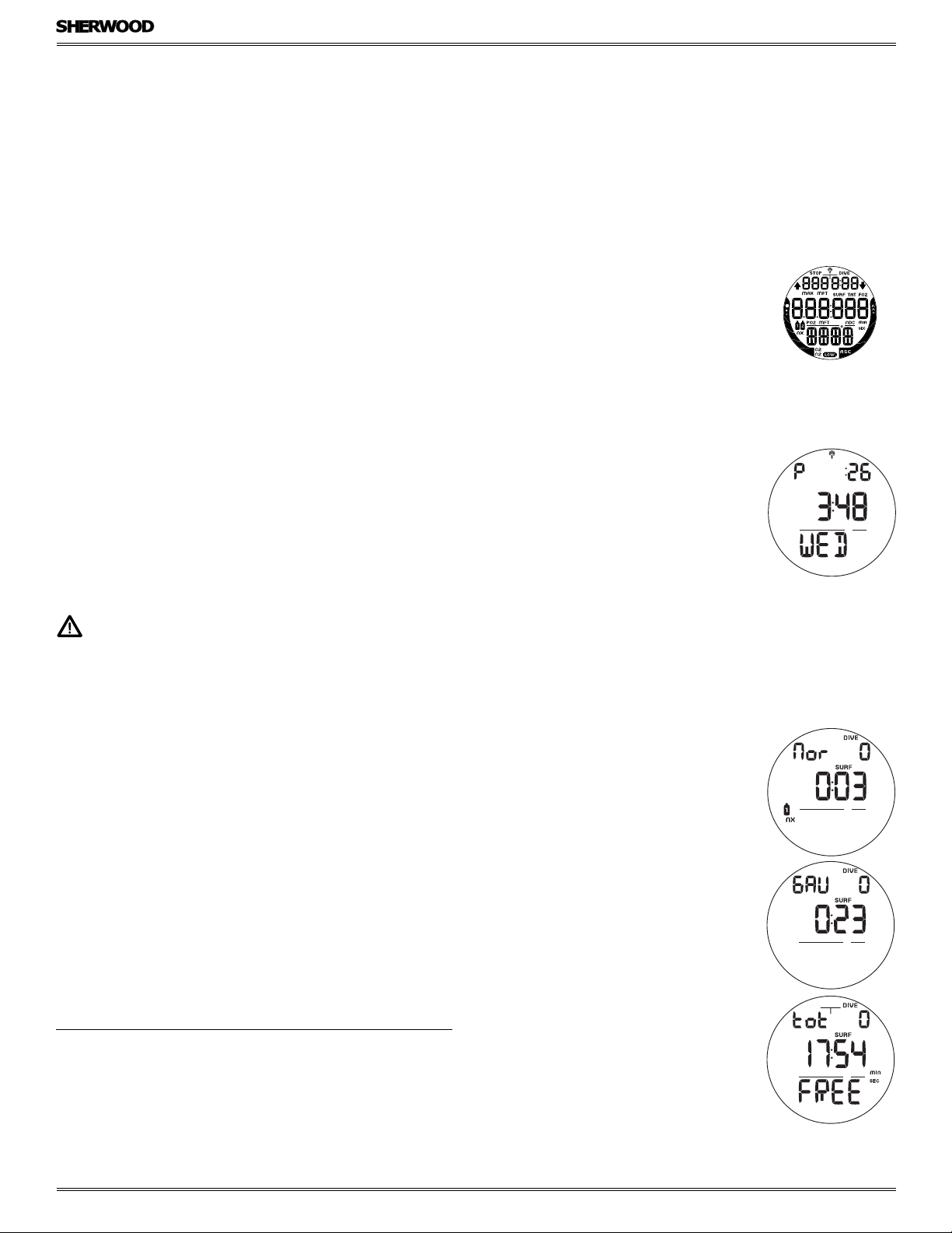
Fig. 1 - WATCH MAIN TIME
A
B
The Audible will not be active if it is Set OFF (a group A setting).
Situations that will activate the NORM/GAUG 10 second Alarm include -
C
• Descent deeper than the Max Depth value selected.
• Dive Time Remaining decreases to the value selected.
• Elapsed Dive Time at the value selected.
• High PO2 increases to the value selected.
• O2 reaches 300 OTU (100% of allowed single or daily exposure).
• Nitrogen Bar Graph at the value (segment) selected.
• NORM/GAUG Ascent Rate Alarm - rate exceeds 60 FPM (18 MPM) when deeper than 60 FT (18 M), or 30 FPM (9 MPM)
at 60 FT (18 M) and shallower.
Fig. 2 - SURFACE MAINS
• Entry into Decompression (NORM).
© 2002 Design, 2012 Doc. No. 12-5301-r01 (12/17/12)
7
Page 8
• Conditional Violation (above a required Deco Stop Depth for less than 5 minutes).
• Delayed Violation (above a required Deco Stop Depth for more than 5 minutes).
• Delayed Violation (a Deco Stop Depth greater than 60 FT/18 M is required).
• Delayed Violation (Maximum Operating Depth of 330 FT/100 M is exceeded).
• A Gas Switch to another tank would expose the diver to PO2 greater than 1.60 ATA.
• Watch Daily Alarm reaches time set (on surface only).
• Watch Countdown Timer reaches 0:00 (on surface only).
A single short beep (which cannot be disabled) is emitted for the following -
• Upon completion of a battery change.
• Change from Delayed to Full Violation 5 minutes after the dive.
3 short beeps (which cannot be disabled) are emitted for the following -
• NORM/GAUG Ascent Rate Warning - rate is 51 to 60 FPM (15.1 to 18 MPM) when deeper than 60 FT (18 M), or 26 to
30 FPM (7.5 to 9 MPM) at 60 FT (18 M) and shallower.
• FREE Dive Elapsed Dive Time Alarm - 3 beeps at each 30 second interval, if set On.
• FREE Dive Depth Alarms 1/2/3 (set sequentially deeper) - each 3 beeps 3 times.
• FREE Dive NIBG Alarm (Caution zone, 4 segments) - 3 beeps 3 times.
• Entry into Deco during a FREE Dive (Violation) - 3 beeps 3 times.
• Free Mode Countdown Timer reaches 0:00 - 3 beeps 3 times.
During the following NORM Dive situations, the 10 second continuous tone will be followed by a 5 second steady beep that
cannot be acknowledged/silenced -
• Ascending above a required Decompression Stop Depth for more than 5 minutes (referred to as a Delayed Violation).
• Decompression requires a Stop Depth of 70 FT (21 M) or deeper.
• Being on the Surface for 5 minutes after a Conditional Violation.
BACKLIGHT
To activate the Backlight, press the L (lower/right) button.
• The Backlight will activate and illuminate the display for button depression time* plus the Duration time set (0, 5, or 10
seconds) for a maximum of 20 seconds.
*The Backlight turns Off if the button is held depressed for more than 10 seconds.
• Press L again to activate as desired.
AMPHOS DC MANUAL
a
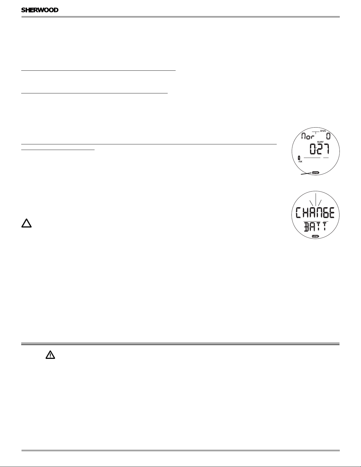
Fig. 3 - LOW BATTERY
WARNING
NOTE: Extensive use of the Backlight reduces estimated Battery life. Also, the Backlight does not
operate during a Low Battery condition or when the AMPHOS is connected to a PC.
POWER SUPPLY
The AMPHOS uses (1) 3 volt CR2430 Lithium Battery. Used as a Dive Computer, the battery should operate normally for 1 year
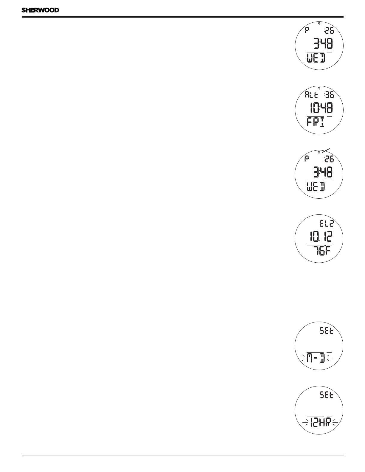
Fig. 4 - LOW BATTERY
ALARM
or 300 dive hours if 2 dives are conducted during each dive period. Voltage is checked every 2 minutes on the surface.
• If voltage decreases to the Warning level (2.75 volts), the Battery icon will appear on Surface Main (Fig. 3a) as an
indication that the Battery should be changed prior to commencing a series of dives.
• If the voltage decreases to the Alarm level (2.50 volts), the Battery icon will flash and the message CHANGE BATT will flash
(Fig. 4) for 5 seconds, then operation will revert to Watch Main Time. The AMPHOS would then only operate in Watch
modes until the Battery becomes completely depleted.
• Low Battery conditions are not displayed during dives.
• If a Low Battery Condition was not displayed prior to starting a Dive, and a Low Battery Condition occurs during the dive,
there will be sufficient Battery power remaining to maintain operation for the remainder of that dive.
WARNINGS AND SAFETY RECOMMENDATIONS
• It should not be considered that the capabilities built into the AMPHOS provide an implied approval or consent from Sherwood for individuals to exceed the dened limits for recreational diving, as agreed on by all internationally recognized training agencies.
• The oxygen features of the AMPHOS are intended for use by recreational divers trained for Nitrox diving by an instructor certied by a
recognized training agency to teach diving with Nitrox.
• Conducting repetitive dives using enriched nitrogen-oxygen mixtures can lead to oxygen buildup, reducing oxygen tolerance while increasing the risk of pulmonary oxygen toxicity.
• The AMPHOS provides information based upon a personal dive prole, and therefore must not be shared between divers. It is impossible
for two divers to stay precisely together underwater, and your computer's dive prole tracking of previous dives will be pertinent to you
only. Nitrogen and oxygen loading of a second user may be signicantly different and swapping dive computers could lead to inaccurate
and dangerous predictions of decompression and oxygen accumulation status.
© 2002 Design, 2012 Doc. No. 12-5301-r01 (12/17/12)
8
Page 9

WATCH
AMPHOS DC MANUAL
FEATURES & DISPLAYS
© 2002 Design, 2012 Doc. No. 12-5301-r01 (12/17/12)
9
Page 10
LOCAL DEFAULT TIME
Watch Main Time (Fig. 5) is the current Time at your home location and is normally selected as the Local Default Time.
The normal Watch screen sequence accessed with momentary presses (less than 2 seconds each) of the M button is -
Main Time >> Alternate Time >> Countdown Timer >> Chronograph >> Daily Alarm
AMPHOS DC MANUAL
Watch Alternate Time (Fig. 6), which is set by Hour Differential, is the current Time at a remote travel location. Upon arrival
at the location, Alternate Time can be interchanged with Main Time to make it the Local Default Time.
While viewing Alternate Time, depressing the S button for 2 seconds will replace Main Time with Alternate Time that will then
become the Local Default Time until changed.
While viewing any of the Watch Mode displays, depressing the M button for 2 seconds or if no button is pressed for 2 minutes,
operation will revert to the Watch Default Time screen selected.
MAIN TIME, information displayed includes (Fig. 7):
> Daily Alarm icon (clock) if it is set On (Fig. 7a).
> Time of Day (hr:min:sec) with P icon (if PM), no icon if AM or if 24 Hour Format.
> Day of the Week graphic MON (or TUE, WED, THU, FRI, SAT, SUN).
> Battery icon, if a Low Battery Condition exists.
> Nitrogen Bar Graph, if any after NORM/FREE dives.
• M (< 2 sec) will access Watch ALT Time (remote, set for travel location).
• M (2 sec) will access Dive Computer Surface Mode (NORM, GAUG, or FREE).
• A (< 2 sec) will access NORM/GAUG Log and History Modes.
• A (2 sec) will access the ALT (Alternate) screen (Elev, Temp, Date).
• S (< 2 sec) will silence/acknowledge the Daily Alarm.
• L (press) will activate the Backlight.
• A + S (simultaneously 2 sec) will access the Set Time menu.
WATCH ALT, information includes (Fig. 8):
> Altitude graphic (EL2 to EL7), if above 3000 feet (915 meters), blank if Sea level.
> Date (Month.Day or Day.Month).
> Temperature with ° icon and graphic F (or C).
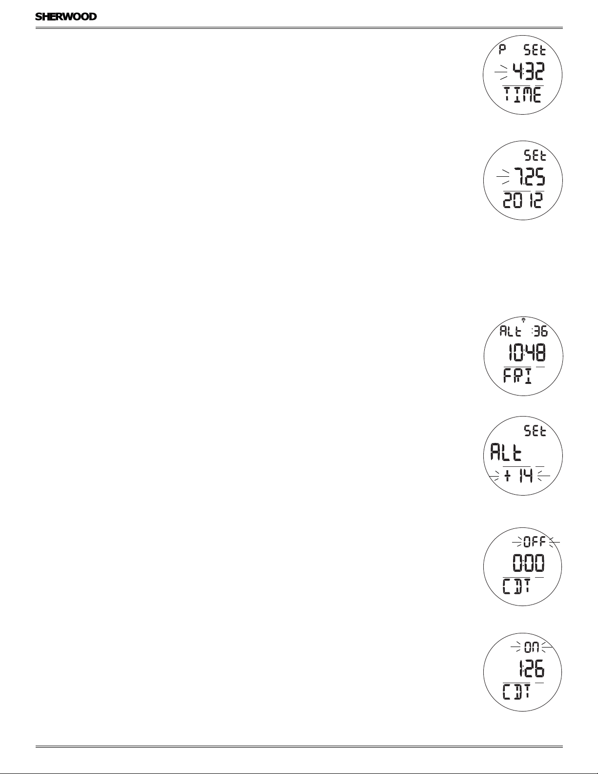
Fig. 5 - MAIN TIME
Fig. 6 - ALTERNATE TIME
a
Fig. 7 - MAIN TIME
(12 Hour Format)
• After 5 seconds, operation will revert to the Watch Time screen.
• A (< 2 sec) will revert to the Watch Default Time screen.
• L (press) will activate the Backlight.
SET MAIN TIME
This mode allows the Date and Time of Day to be set which will also serve as the basis for Watch Alternate Time values.
> Set items include Date Format, Hour Format, Time, and Date
> Day of the Week is set automatically when the Date is set.
> When the AMPHOS is operating in Dive Computer mode, Date is displayed only to identify dives when they are accessed in
the Log Mode
• A (repeatedly, < 2 sec each time) will step through the menu items.
• M (2 sec) at any time, or if no button is pressed during a period of 2 minutes, operation will revert to Watch Default Time.
Set Date Format
While viewing the Watch Default Time screen, depressing the A and S buttons simultaneously for 2 seconds will access the Set
Date Format screen displaying the graphic SEt and the Set Point M - D (or D - M) flashing (Fig. 9).
> M - D means that Month will be displayed to the left of Day.
> D - M means that Day will be displayed to the left of Month.
• S (< 2 sec) will toggle between M - D and D - M.
• A (< 2 sec) will save the setting and access Set Hour Format.
Set Hour Format
The Set Hour Format screen displays the graphic SEt with the Set Point 12HR (or 24HR) flashing (Fig. 10).
• S (< 2 sec) will toggle between 12 and 24.
• A (< 2 sec) will save the setting and access Set Time.
Fig. 8 - WATCH ALT
Fig. 9 - SET DATE FORMAT
Fig. 10 - SET HOUR FORMAT
© 2002 Design, 2012 Doc. No. 12-5301-r01 (12/17/12)
10
Page 11
Set Time
The Set Time screen displays the graphics SEt and TIME with the Time of Day (hr:min) with the Hour digits flashing (Fig. 11). The
graphic P is displayed when PM, no graphic if AM or 24 Hour Format.
• S (press/hold) will scroll upward through the Hour Set Points in 1 hour increments at a rate of 8 per second.
• S (< 2 sec) will step upward through the Set Points one at a time.
• A (< 2 sec) will save the Hour setting and flash the Minute digits.
• S (press/hold) will scroll upward through the Minute Set Points in 1 minute increments at a rate of 8 per second.
• S (< 2 sec) will step upward through the Set Points one at a time.
• A (< 2 sec) will save the Minute Set Point and access Set Date.
Set Date
The Set Date screen displays the graphic SEt and Month.Day (or Day.Month) with the Year digits flashing (Fig. 12).
• S (press/hold) will scroll upward through the Year Set Points in 1 Year increments at a rate of 8 per second from 2011 to
2054 (with leap year corrections).
• S (< 2 sec) will step upward through the Year Set Points one at a time.
• A (< 2 sec) will save the Year setting and flash the Month digits (regardless of their position on the display).
• S (press/hold) will scroll upward through the Month Set Points in 1 month increments at a rate of 8 per second.
• S (< 2 sec) will step upward through the Month Set Points one at a time.
• A (< 2 sec) will save the Month Set Point and flash the Day digits.
• S (hold) will scroll upward through the Day Set Points in 1 Day increments at a rate of 8 per second.
• S (repeatedly, < 2 sec each time) will step upward through the Day Set Points one at a time.
• A (< 2 sec) will save the Date setting and revert to Watch Default Time.
> Year will not be displayed in any mode other than Set Date.
> Main Time/Date can also be set using the PC Interface program.
> Prior to shipment from the factory, any error of the Main Time is corrected.
AMPHOS DC MANUAL
Fig. 11 - SET TIME
Fig. 12 - SET DATE
ALTERNATE TIME, information includes (Fig. 13):
> Alarm icon, if the Daily Alarm is set On, blank if Off.
> Graphic ALt, indicating Time as Alternate (remote location).
> Time of Day (hr:min:sec), blank if Off.
> Day of the Week graphic MON (or TUE, WED, THU, FRI, SAT, SUN), or OFF.
• S (< 2 sec) will silence/acknowledge the Daily Alarm.
• S (2 sec) will interchange ALT Time with Main Time making ALT Time the local Watch Default Time screen.
• A + S (2 sec) will access Set ALT Time.
• M (< 2 sec) will access the Watch CDT Status (Countdown Timer).
• M (2 sec) will revert to the Watch Default Time screen.
• L (press) will activate the Backlight.
Set Alternate Time
• ALT TIME can be set OFF, or to an Hour Differential ranging from + 1 through +23 through - 23 through -1 (hours).
• Once the Differential is selected and saved, values of ALT Time will be based upon the Main Time setting.
Information includes (Fig. 14):
> Graphics SEt and ALt.
> Graphic OFF (or numeric value) flashing.
• S (press/hold) will scroll through the Set Points in increments of 1 Hour at a rate of 8 per second.
• S (< 2 sec) will step upward through the Set Points one at a time.
• A (< 2 sec) will save the Set Point and revert to the Watch ALT Time screen.
• M (2 sec) will revert to the Watch Default Time screen.
• If no button is pressed during a period of 2 minutes, operation will revert to the Watch Default Time screen.
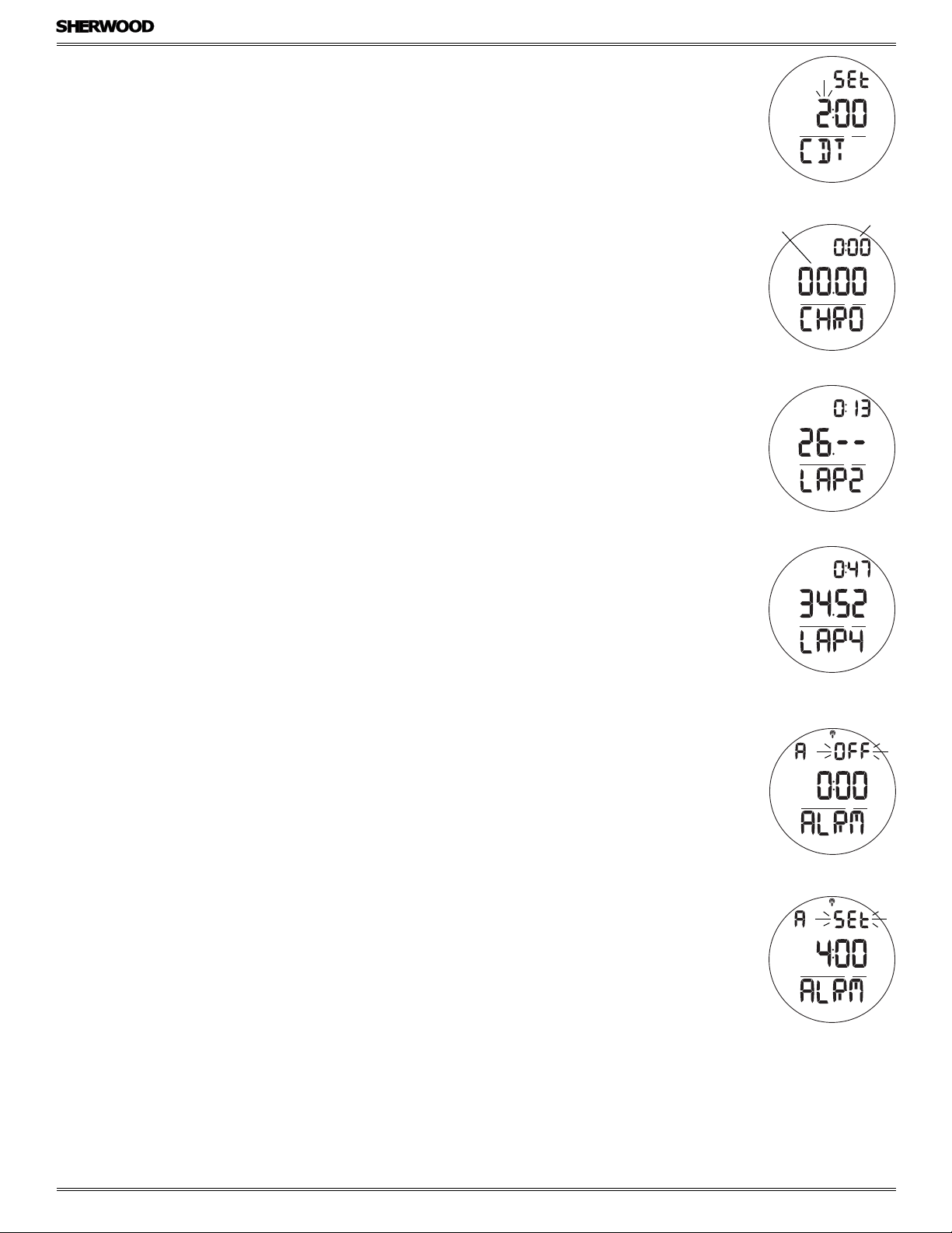
WATCH CDT (COUNTDOWN TIMER) STATUS, information includes (Fig. 15, 16):
> Graphic OFF (or ON) flashing, with 0:00 if no time was previously set, the remaining Countdown Time (hr:min) if running,
or the Countdown Time previously set.
> Graphic CDT.
• S (< 2 sec) will toggle between ON and OFF. A toggle to ON will Start the Timer if a Time has been set.
>> If OFF is selected, the CD Time in progress will stop counting down. Access to Set will be allowed.
>> If ON is selected, the CD Time displayed (time previously set, or the time remaining when stopped) will start counting
down. Access to Set will be blocked.
• A + S (2 sec) will display the graphic SEt in place of OFF, allowing the Time to be set.
• M (< 2 sec) will access Chrono.
• M (2 sec) will revert to the Watch Default Time screen.
• L (press) will activate the Backlight.
Fig. 13 - ALTERNATE TIME
Fig. 14 - SET ALTERNATE
TIME
Fig. 15 - CDT STATUS
(no time set)
Once set ON, a CDT will run in the background (on surface) until turned OFF, or it counts down to 0:00 at which time the
alarm will strike. Upon entry into Dive Mode the CDT will turn OFF with the Time reverting to the value previously set.
© 2002 Design, 2012 Doc. No. 12-5301-r01 (12/17/12)
11
Fig. 16 - CDT STATUS
(running)
Page 12
Set CDT, information includes (Fig. 17):
> Graphic SEt with last Time (hr:min) set, Hour digits flashing.
> Graphic CDT.
• S (press/hold) will scroll upward through the Hour Set Points in 1 hour increments at a rate of 8 per second.
• S (< 2 sec) will step upward through the Set Points one at a time.
• A (< 2 sec) will save the Hour setting and flash the Minute digits.
• S (press/hold) will scroll upward through the Minute Set Points in 1 minute increments at a rate of 8 per second.
• S (< 2 sec) will step upward through the Set Points one at a time.
• A (< 2 sec) will save the Minutes setting and revert to the CDT Status screen with the graphic OFF flashing in place of SEt.
• S (< 2 sec) will toggle from OFF to ON, starting countdown.
• M (2 sec), or no button press for 2 min, will revert to Watch Default Time.
CHRONOGRAPH STATUS (Stop Watch, Lap Timer), information includes (Fig. 18, 19):
> 0:00:00.00, or total elapsed run time (hr:min & sec. 1/100th sec) if previously started and running.
> Graphic CHRO if not running, or LAP1 (2 to 9, the one in progress) if running.
• S (< 2 sec) will Start the Timer which will begin counting up from 0:00:00.00 to 9:59:59.99 (hr:min_ _sec.1/100th sec) in
increments of .01 (1/100th sec).
During the first 4 seconds the 1/100th second values will be displayed after which 2 dashes ( . - - ) will be displayed.
The 1/100th values will be recorded and displayed when Laps are frozen and when later recalled.
• Subsequent presses of S (< 2 sec) will freeze Lap Times (LAP 1 through LAP 9). After 9 Laps are recorded, additional Laps
will replace LAP 9, shift the others to lower LAP numbers, while discarding LAP 1.
If the Timer reaches 9:59:59.99, it will stop and save that as a LAP. Subsequent presses of S will then have no effect.
AMPHOS DC MANUAL
Fig. 17 - SET WATCH CDT
sec_.01 sec
Fig. 18 - CHRONO STATUS
(not running)
hr:min
• A (< 2 sec) will Stop the Timer and Recall LAP 1, displaying the graphic LAP1 and Lap Time. Repeat presses will display
other Laps (2 to 9).
• A (2 sec) will Stop the Timer and Reset the Time to 0:00:00.00.
• M (< 2 sec) will access Daily Alarm Status.
• M (2 sec), or no button press for 2 min, will revert to Watch Default Time.
While the Chrono is running, it will remain on the screen until a button operation is performed. If another screen is accessed, it
will then continue to run in the background.
Upon descending on a dive, Chrono operation will be terminated and reset to 0:00:00.00.
DAILY ALARM STATUS, information includes (Fig. 21):
> Graphic ON (or OFF), flashing.
> Alarm Time last set (hr:min) with A (or P) icon.
> Graphic ALRM and alarm icon.
• S (< 2 sec) will toggle between ON and OFF.
>> If OFF is selected, alarm activation is disabled. Access to Set will be allowed.
>> If ON is selected, the alarm time set is enabled. Access to Set will be blocked.
• A + S (2 sec) will display the graphic SEt in place of OFF, allowing the Time to be set.
• M (< 2 sec) will revert to Watch Default Time.
• M (2 sec), or no button press for 2 min, will revert to Watch Default Time.
• L (press) will activate the Backlight.
Set Daily Alarm, information provided includes (Fig. 22):
> Graphic SEt.
> Alarm Time previously set (hr:min), Hour digits flashing.
> Graphic ALRM and alarm icon.
• S (press/hold) will scroll upward through the Hour Set Points in 1 hour increments at a rate of 8 per second.
• S (< 2 sec) will step upward through the Set Points one at a time.
• A (< 2 sec) will save the Hour setting and flash the Minute digits.
• S (press/hold) will scroll upward through the Minute Set Points in 1 minute increments at a rate of 8 per second.
• S (< 2 sec) will step upward through the Set Points one at a time.
• A (< 2 sec) will save the Minutes setting and revert to the Daily Alarm Status, the graphic OFF flashing in place of SEt.
• S (< 2 sec) will toggle from OFF to ON, starting countdown.
Fig. 19 - CHRONO STATUS
(Lap in progress)
Fig. 20 - LAP RECALL
Fig. 21 - DAILY ALARM
Fig. 22 - SET DAILY ALARM
Once the Daily Alarm has been set and turned ON, it will run in the background while on the surface until turned OFF.
Alarm time is synchronized with the local Default Time selected for the current location. It will also run in the background
while in Dive Computer modes but will not sound the audible or flash the icon when the alarm time is reached during dives.
© 2002 Design, 2012 Doc. No. 12-5301-r01 (12/17/12)
12
Page 13

DIVE COMPUTER
AMPHOS DC MANUAL
FEATURES & DISPLAYS
© 2002 Design, 2012 Doc. No. 12-5301-r01 (12/17/12)
13
Page 14
BAR GRAPHS
The AMPHOS features 2 bar graphs, one on each side of the LCD.
• The one on the left (Fig. 23a) is dual function. It represents either Nitrogen loading or Oxygen accumulation. The icons N2
and O2 identify which is displayed at that time.
Regardless of which parameter the Bar Graph is representing at the time,
nitrogen and oxygen calculations will continue to be performed in the background.
• The one on the right (Fig. 23b) represents Ascent Rate. It is referred to as the ASC (Ascent Rate Indicator).
NIBG (Nitrogen Bar Graph)
The NIBG represents tissue loading of nitrogen, showing your relative no decompression or decompression status. As your
depth and elapsed dive time increase, segments will add to the NIBG, and as you ascend to shallower depths, the segments will
recede, indicating that additional no decompression time is allowed for multilevel diving.
The NIBG monitors 12 different nitrogen compartments simultaneously and displays the one that is in control of your dive. It is divided into a No Decompression (normal) zone, a Caution zone (also No Decompression), and a Decompression (danger) zone.
While you cannot provide a guarantee against the occurrence of decompression sickness, you may choose your own personal
zone of caution based upon age, physique, excessive weight, etc., to reduce the statistical risk.
NOTE: Information associated with oxygen and the O2BG will only be displayed when FO2 has been
set for Nitrox (e.g., a numerical value).
Oxygen Bar Graph (O2BG)
The O2BG represents oxygen accumulation, showing the maximum of either per dive accumulated oxygen, or 24 hour period
accumulated oxygen.
As your oxygen exposure (accumulation) increases during the dive, segments will add to the O2BG, and as saturation decreases,
it will begin to recede, indicating that additional exposure is allowed for that dive and 24 hour period.
AMPHOS DC MANUAL
a
Fig. 23 - BAR GRAPHS
ASC values
Deeper than 60 FT (18 M)
Segments Ascent Rate =
Displayed FPM MPM
0 0 - 20 0 - 6
1 21-50 6.5-15
2 51-60 15.5-18
3 >60 >18
60 FT (18 M) & Shallower
Segments Ascent Rate =
Displayed FPM MPM
0 0 - 10 0 - 3
1 11-25 3.5-7.5
2 26-30 8-9
3 >30 >9
a
b
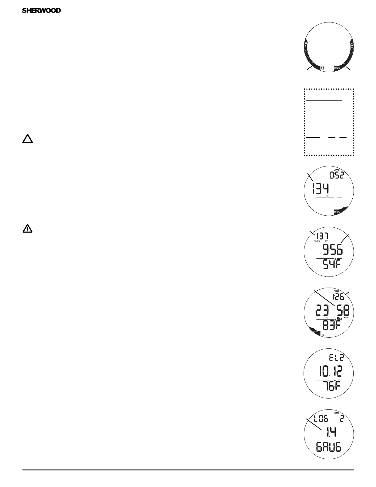
Ascent Rate Indicator (ASC)
The ASC provides a visual representation of ascent speed (i.e., an ascent speedometer).
The segments of the ASC represent two sets of speeds that change at a reference Depth of 60 FT (18 M).
See chart at right.
WARNING: At depths greater than 60 FT (18 M), ascent rates should not exceed 60 FPM (18 MPM).
At depths of 60 FT (18 M) and shallower, ascent rates should not exceed 30 FPM (9 MPM).
ALPHA / NUMERIC DISPLAYS
Depth
During dives, the Current Depth display (Fig. 24a) and Maximum Depth which is on an Alternate Display (Fig. 25a) indicate
Depths from 0 to 330 FT (100 M) in increments of 1 FT (0.1 M).
No Deco Deep and Safety Stops, as well as Decompression Stops, display required Stop Depths.
Time and Date
Most Time displays like Time of Day (Fig. 25b) are shown in hour:minute format (i.e., 9:56 represents 9 hours and 56 minutes,
not 956 minutes!). The colon that separates hr:min (min;sec) blinks once per second when the display is indicating real time
(e.g., Time of Day).
Other times displayed include NDC (No Deco Time Remaining, Fig. 26a), and EDT (Elapsed Dive Time, Fig. 26b).
No Deco Stops and FREE Dive Mode times are displayed in minute:second format.
Temperature, Date, Elevation
Elevation, Date, and Temperature can be viewed by accessing the Watch Alternate Display (Fig. 27).
The only other place that Date is displayed is on Log Preview screens that identify dives (Fig. 28a).
Fig. 24 - DEPTH
a
Fig. 25 - MAX DEPTH, TIME
a
Fig. 26 - NDC, EDT
b
b
When above the sea level range, which extends up to 3000 feet (915 meters), Altitude is displayed as EL (Elevation Level) from 2
up to 7.
EL2 = 3,01 to 5000 feet (916 to 1525 meters)
EL3 = 5001 to 7000 feet (1526 to 2135 meters)
EL4 = 7001 to 9000 feet (2136 to 2745 meters)
EL5 = 9001 to 11000 feet (2746 to 3355 meters)
EL6 = 11001 to 13000 feet (3356 to 3965 meters)
EL7 = 13001 to 14000 feet (3966 to 4270 meters)
© 2002 Design, 2012 Doc. No. 12-5301-r01 (12/17/12)
14
Fig. 27 - ELEV, DATE, TEMP
a
Fig. 28 - DATE
Page 15

DIVE COMPUTER
AMPHOS DC MANUAL
SURFACE MODES
© 2002 Design, 2012 Doc. No. 12-5301-r01 (12/17/12)
15
Page 16

DIVE COMPUTER (DC) OPERATING MODES
The AMPHOS features 3 DC Operating Modes -
• NORM >> for normal Air or Nitrox SCUBA dives.
• GAUG >> for SCUBA dives with no nitrogen/oxygen calculations.
• FREE >> for dives with no SCUBA.
SURFACE MODE
Depressing the M button for 2 seconds while Watch Default Time is displayed will access NORM Surface Main (Fig. 29) which is
the default dive computer mode until another is selected.
• GAUG and FREE Surface Main screens (Fig. 30, 31) can be accessed by pressing M for 2 seconds while viewing NORM
Surface Main. Their graphics will flash indicating that they can be selected as the Operating Dive Mode.
• To select GAUG or FREE for diving, press/release M (< 2 sec) while the mode graphic (GAU or FREE) is flashing. When the
graphic becomes solid, that Mode is selected.
• The operating mode selected will remain on display for 2 hours until a dive is made or another mode is selected.
Once a dive has been conducted, the Surface Main for that mode will be displayed.
AMPHOS DC MANUAL
Fig. 29 - NORM SURF MAIN
Operation will enter Dive Mode upon descent to 5 FT (1.5 M) for 5 seconds.
• During the 2 hour pre dive surface period, if the M button is pressed to access Watch Mode, DC Surface Mode must again
be accessed prior to the first dive of a series (if Wet Activation is set OFF).
• When Wet Activation is set ON, the wet contacts will activate the selected Dive Mode regardless of what Mode the
AMPHOS is operating in at the time of the descent.
The AMPHOS will enter post dive Surface Mode upon ascent to 2 FT (0.6 M) for 1 second. The Surface Interval Time colon will
flash during the first 10 minutes after a NORM or GAUG dive, or 1 minute after a FREE dive.
During the first 10 minutes after a dive, the Surface Main screen for the operating mode remains on display. Watch Default Time
can be viewed for 5 seconds during that period by pressing/releasing M (< 2 sec).
When the 10 minute Surface Time has elapsed, Watch Default Time will replace the DC Surface Main which can then be accessed by depressing M (2 sec).
NORM SURF MAIN, information includes (Fig. 32):
> Graphic Nor (indicating NORM mode).
> Number of recent dive completed (0 if no dive made yet) with DIVE icon.
> Surface Interval Time (hr:min) with SURF icon.
> Gas (tank) 1 icon, 1 is the default on the surface.
> NX icon, if either gas is set for Nitrox.
> Battery icon if a Low Battery warning condition exists.
> NIBG with N2 icon, if any residual nitrogen after a NORM or FREE dive.
• A (2 sec) will access NORM SURF ALT 1.
• A (< 2 sec) will access Log Mode, then again History.
• A + S (2 sec) will access the Set Modes.
• M (2 sec) will access GAUG Surface Main, then another 2 seconds FREE Surface Main.
• M (< 2 sec) will revert to Watch Default Time.
• S (< 2 sec) will access Plan Mode, then again after dives Time to Fly, then Dsat Time.
• L (press) will activate the Backlight.
Fig. 30 - GAUG SURF MAIN
Fig. 31 - FREE SURF MAIN
Fig. 32 - NORM SURF MAIN
(post dive)
NORM SURF ALT 1, information includes (Fig. 33):
> Altitude graphic EL2 to EL7, if above 3000 feet (915 meters), blank if Sea level.
> Time of Day (hr:min).
> Temperature with ° icon and graphic F (or C).
• A (< 2 sec) will access ALT 2 (after Nitrox dives), or revert to NORM SURF Main.
Fig. 33 - NORM SURF ALT 1
• After 5 sec, operation will revert to NORM SURF Main.
• L (press) will activate the Backlight.
NORM SURF ALT 2, information includes (Fig. 34):
> FO2 set for Gas in use at end of dive.
> Gas (tank) 1 (or 2) icon, one in use at end of dive.
> O2BG with O2 icon, current level of O2.
• A (< 2 sec) will revert to NORM SURF Main.
• After 5 sec, operation will revert to NORM SURF Main.
• L (press) will activate the Backlight.
© 2002 Design, 2012 Doc. No. 12-5301-r01 (12/17/12)
16
Fig. 34 - NORM SURF ALT 2
(only after Nitrox dives)
Page 17

NORM/GAUG SET MODES
Sequence >> SURF Main > Set F (FO2) > Set A (Alarms) > Set U (Utilities) > SN (Serial Number).
> Access and step through of the sequence is gained by simultaneous 2 second presses of A and S.
> Alarms and Utilities can also be set/changed using the PC Interface program. FO2 must be set using the push buttons.
> Settings remain at the values saved until they are changed.
SETTING FO2 FOR NITROX DIVES
For each value of FO2, the MOD (Max Operating Depth) that can be achieved for the PO2 Alarm value set will be displayed.
When the FO2 50% Default is set On and FO2 Gas 1 is set for a numerical value, 10 minutes on the surface after that dive, FO2
for Gas 1 will be displayed as 50 and further dives will be calculated based on 50% O2 for oxygen calculations and 21% O2
for Nitrogen calculations (79% Nitrogen), unless the FO2 for Gas 1 is set before the dive.
FO2 for Gas 1 continues to reset to the FO2 50% Default after subsequent repetitive dives until 24 hours elapse after the last
dive, or the FO2 50% Default is turned Off.
When the FO2 50% Default is set Off, the FO2 for Gas 1 will remain at the last value saved for the remainder of that series of
repetitive dives.
FO2 SET FOR AIR
The default FO2 for Gas 1 each new dive period is AIR.
When FO2 for Gas 1 is set for AIR, calculations are the same as when it is set for 21%. When FO2 for Gas 1 is set to AIR, it
remains set for AIR until it is set for a numerical FO2 value (21 to 50%).
When FO2 is set only to AIR, the O2BG and PO2 values and/or warnings will not be displayed during the dive.
MODs affected by the PO2 limit set will not be displayed when FO2 for Gas 1 is set to AIR.
AMPHOS DC MANUAL
Internally, the AMPHOS keeps track of the O2 so that if FO2 for Gas 1 is subsequently set for a numerical value, the O2 accumulated during previous AIR dives will be accounted for in the next Nitrox dive (during that dive period and series of repetitive
dives).
Once FO2 Gas 1 is set for a numerical value (21 to 50%) and a dive is made, the AIR option is disabled until 24 hours elapse
after the last dive. The AIR option will not be displayed in Set FO2 Gas 1 until a full 24 hour Surface Interval has elapsed.
If FO2 for Gas 1 is set for 21%, it will remain set for 21% for that series of dives until set for a higher numerical value.
If the FO2 50% Default is set Off, FO2 for Gas 2 will remain as previously set until it is changed. If the FO2 50% Default is set
On, FO2 for Gas 2 will Default to 50% after the dive.
SET F GROUP (FO2)
Selections >> Gas 1 > Gas 2 > 50% Default.
> A + S (2 sec), while viewing NORM SURF Main, will access Set F (Fig. 35).
> A (< 2 sec) will then access Set FO2 Gas 1.
SET FO2 GAS 1, information includes (Fig. 36):
> Max Depth with MAX and FT (or M) icons, allowed for the PO2 Alarm Set, blank if Air.
> PO2 Alarm set with PO2 icon, blank if Air.
> FO2 setting flashing with FO2 icon, either the graphic Air or Nitrox (numerical) value with NX icon.
> Tank 1 icon, representing gas (mix) 1.
> Graphic GAS1.
• S (hold) will scroll upward through the Set Points from Air to 21 through 50% in 1% increments, at a rate of 8 per second.
• The scroll will stop when S is released, or momentarily at 32% (even if S is held depressed).
• Depressing S again will resume the scroll from 32 through 50%, then stop at Air (or 21%).
• S (< 2 sec) will step upward through the Set Points one at a time.
• A (< 2 sec) will save the setting and access Set FO2 Gas 2.
• A + S (2 sec) will save the setting and revert to Set F.
• M (2 sec), or if no button is pressed within 2 minutes, operation will revert to the Surface Main.
Fig. 35 - SET F GROUP
Fig. 36 - SET FO2 GAS 1
SET FO2 GAS 2, information includes (Fig. 37):
> Max Depth with MAX and FT (or M) icons, allowed for the PO2 Alarm Set, blank if Air.
> PO2 Alarm set with PO2 icon, blank if Air.
> FO2 setting flashing graphic Air or Nitrox (numerical) value with NX icon.
> Tank 2 icon, representing gas (mix) 2.
> Graphic GAS2.
• S (hold) will scroll through the Set Points from AIR to 21 through 100% in 1% increments, at a rate of 8 per second.
• The scroll will start at the FO2 Gas 1 Set Point* and stop when S is released, or momentarily at 50%, then again at 80%,
then at the Gas 1 Set Point or at AIR (or 21%).
© 2002 Design, 2012 Doc. No. 12-5301-r01 (12/17/12)
17
Fig. 37 - SET FO2 GAS 2
Page 18

• S (< 2 sec) will step through the Set Points one at a time.
• A (< 2 sec) will save the setting and access Set FO2 Default.
• A + S (2 sec) will save the setting and revert to Set F.
• M (2 sec), or if no button is pressed within 2 minutes, operation will revert to the Surface Main.
*
The AMPHOS is programmed to prevent FO2 for Gas 2 from being set at a value lower than the FO2 set for Gas 1. When
setting FO2 for Gas 2, the lowest value available will be the Set Point of Gas 1.
SET FO2 50% DEFAULT, information includes (Fig. 38):
> Graphics FO2, dFLt, and 50.
> Set Point graphic OFF (or ON), flashing.
• S (< 2 sec) will toggle between OFF and ON.
• A (< 2 sec) will save the setting and revert to SET F.
• M (2 sec), or if no button is pressed within 2 minutes, operation will revert to the Surface Main.
AMPHOS DC MANUAL
SET A GROUP (ALARMS)
Selections >> Audible > Depth > EDT > NIBG > DTR > PO2.
> A + S (2 sec), while viewing Set F, will access Set A (Fig. 39).
> A (< 2 sec) will then access Set Audible.
SET AUDIBLE, information includes (Fig. 40):
This option allows the Audible Alarm to be disabled. Due to their importance, some cautionary situations will cause the Audible
to sound even if this feature is set to Off.
> Graphic ON (or OFF), flashing.
> Graphic AUD.
• S (< 2 sec) will toggle between ON and OFF.
• A (< 2 sec) will save the setting and access Set Depth Alarm.
• A + S (2 sec) will save the setting and revert to Set A.
• M (2 sec), or if no button is pressed within 2 minutes, operation will revert to the Surface Main.
SET DEPTH ALARM information includes (Fig. 41):
> Graphic ON (or OFF), flashing.
> Depth value with MAX and FT (or M) icons.
> Graphic DEEP.
• S ( < 2 sec) will step through the selections OFF, ON, and SEt.
• A (< 2 sec) will save the selection >> if ON or OFF is saved, advance to Set EDT Alarm.
>> if SEt is saved, the Depth digits flash (SEt goes solid).
• S (hold) will scroll upward from 30 to 330 FT (9 to 99 M) in 10 FT (1 M) increments at 8 per sec.
• S ( < 2 sec) will step up through the Set Points one at a time.
• A (< 2 sec) will save the setting and flash SEt allowing ON or OFF to be selected..
• A + S (2 sec) will save the setting and revert to Set A.
• M (2 sec), or if no button is pressed within 2 minutes, operation will revert to the Surface Main.
Fig. 38 - SET FO2 DEFAULT
Fig. 39 - SET A GROUP
Fig. 40 - SET AUDIBLE
Fig. 41 - SET DEPTH ALARM
SET EDT ALARM, information includes (Fig. 42):
> Graphic ON (or OFF), flashing.
> Elapsed Dive Time (hr:min).
> Graphic EDT.
• S ( < 2 sec) will step through the selections OFF, ON, and SEt.
• A (< 2 sec) will save the selection >> if ON or OFF is saved, advance to Set NIBG Alarm.
>> if SEt is saved, the Time digits flash (SEt goes solid).
Fig. 42 - SET EDT ALARM
• S (hold) will scroll upward from 0:10 to 3:00 (hr:min) in 0:05 (5 min) increments at 8 per sec.
• S ( < 2 sec) will step up through the Set Points one at a time.
• A (< 2 sec) will save the setting and flash SEt allowing ON or OFF to be selected..
• A + S (2 sec) will save the setting and revert to Set A.
• M (2 sec), or if no button is pressed within 2 minutes, operation will revert to the Surface Main.
© 2002 Design, 2012 Doc. No. 12-5301-r01 (12/17/12)
18
Page 19

SET NIBG ALARM, information includes (Fig. 43):
> Graphic ON (or OFF), flashing.
> Bar graph segments with N2 icon.
> Graphic NIBG.
• S ( < 2 sec) will step through the selections OFF, ON, and SEt.
• A (< 2 sec) will save the selection >> if ON or OFF is saved, advance to Set DTR Alarm.
>> if SEt is saved, the bar graph segments flash (SEt goes solid).
• S (< 2 sec) will step up from 1 to 5 segments in 0:05 (5 min) increments one at a time.
• A (< 2 sec) will save the setting and flash SEt allowing ON or OFF to be selected.
• A + S (2 sec) will save the setting and revert to Set A.
• M (2 sec), or if no button is pressed within 2 minutes, operation will revert to the Surface Main.
SET DTR (DIVE TIME REMAINING or RESERVE TIME) ALARM, information includes (Fig. 44):
> Graphic ON (or OFF), flashing.
> Reserve Time (min) with min icon.
> Graphic DTR.
• S ( < 2 sec) will step through the selections OFF, ON, and SEt.
• A (< 2 sec) will save the selection >> if ON or OFF is saved, advance to Set PO2 Alarm.
>> if SEt is saved, the Time digits flash (SEt goes solid).
• S (hold) will scroll upward from 5 to 20 (min) in 1 min increments at 4 per sec.
• S ( < 2 sec) will step up through the Set Points one at a time.
• A (< 2 sec) will save the setting and flash SEt allowing ON or OFF to be selected.
• A + S (2 sec) will save the setting and revert to Set A.
• M (2 sec), or if no button is pressed within 2 minutes, operation will revert to the Surface Main.
AMPHOS DC MANUAL
Fig. 43 - SET NiBG ALARM
Fig. 44 - SET DTR ALARM
SET PO2 ALARM information includes (Fig. 45):
> Graphic ON (or OFF), flashing.
> PO2 value with PO2, MAX, and NX icons.
> Graphic PO2.
• S ( < 2 sec) will step through the selections OFF, ON, and SEt.
• A (< 2 sec) will save the selection >> if ON or OFF is saved, revert to Set A.
>> if SEt is saved, the PO2 digits flash (SEt goes solid).
• S (< 2 sec) will step up from 1.20 to 1.60 (ATA) in .10 increments one at a time.
• A (< 2 sec) will save the setting and flash SEt allowing ON or OFF to be selected.
• A + S (2 sec) will save the setting and revert to Set A.
• M (2 sec), or if no button is pressed within 2 minutes, operation will revert to the Surface Main.
SET U GROUP (UTILITIES)
Selections >> Wet Activation > Units > Deep Stop > Safety Stop > Conservative Factor > Backlight Duration > Sampling Rate.
> A + S (2 sec), while viewing Set A, will access Set U (Fig. 46).
> A (< 2 sec) will then access Set Wet Activation.
SET WET ACTIVATION, information includes (Fig. 47):
> Graphic OFF (or ON) flashing.
> Graphics Activ WET.
• S (< 2 sec) will toggle between ON and OFF.
• A (< 2 sec) will save the setting and access Set Units.
• A + S (2 sec) will save the setting and revert to Set U.
• M (2 sec), or if no button is pressed within 2 minutes, operation will revert to the Surface Main.
Fig. 45 - SET PO2 ALARM
Fig. 46 - SET U GROUP
Fig. 47 - SET WET
ACTIVATION
SET UNITS, information includes (Fig. 48):
> FT (or M) icons flashing.
> Graphics UNIT.
• S (< 2 sec) will toggle between Imperial and Metric.
• A (< 2 sec) will save the setting and access Set Deep Stop.
• A + S (2 sec) will save the setting and revert to Set U.
• M (2 sec), or if no button is pressed within 2 minutes, operation will revert to the Surface Main.
Fig. 48 - SET UNITS
© 2002 Design, 2012 Doc. No. 12-5301-r01 (12/17/12)
19
Page 20

SET NORM DEEP STOP, information includes (Fig. 49):
> Graphic OFF (or ON) flashing.
> Graphics dEEP STOP.
• S (< 2 sec) will toggle between OFF and ON.
• A (< 2 sec) will save the setting and access Set Safety Stop.
• A + S (2 sec) will save the setting and revert to Set U.
• M (2 sec), or if no button is pressed within 2 minutes, operation will revert to the Surface Main.
When the Deep Stop is set On, a Stop screen will appear upon ascent to within 10 FT (3 M) below the calculated Stop Depth
which is at 1/2 the Max Depth achieved after being deeper than 80 FT (24 M) for 1 second.
SET NORM SAFETY STOP, information includes (Fig. 50):
> Graphic OFF (or ON) flashing.
> Graphics SAFEtY STOP.
• S (< 2 sec) will toggle between OFF and ON.
• A (< 2 sec) will save the setting and access Set Conservative Factor.
• A + S (2 sec) will save the setting and revert to Set U.
• M (2 sec), or if no button is pressed within 2 minutes, operation will revert to the Surface Main.
When the Safety Stop is set On, a Stop screen will appear upon ascent to 20 FT (6 M) indicating that a Stop is to be taken at
15 FT (5 M) for 3 minutes after being deeper than 30 FT (9 M) for 1 second.
SET CONSERVATIVE FACTOR (CF), information includes (Fig. 51):
> Graphic OFF (or ON) flashing.
> Graphics CF.
AMPHOS DC MANUAL
Fig. 49 - SET DEEP STOP
Fig. 50 - SET SAFETY STOP
• S (< 2 sec) will toggle between OFF and ON.
• A (< 2 sec) will save the setting and access Set Backlight Duration.
• A and S (simultaneously for 2 sec) will save the setting and revert to SET U.
• M (2 sec), or if no button is pressed within 2 minutes, operation will revert to the Surface Main.
When the Conservative Factor is set ON, the No Deco Limits are reduced to those that would be available at the next higher
3000 foot (915 meter) Altitude.
SET BACKLIGHT DURATION, information includes (Fig. 52):
> Graphic OFF (or ON) flashing.
> Graphics dur GLO.
> Duration time (min) with min icon.
• S ( < 2 sec) will step through the selections OFF, ON, and SEt.
• A (< 2 sec) will save the selection >> if ON or OFF is saved, advance to Set Sampling Rate.
>> if SEt is saved, the Time digits flash (SEt goes solid).
• S (< 2 sec) will toggle between 5 and 10 (seconds).
• A (< 2 sec) will save the setting and flash SEt allowing ON or OFF to be selected.
• A + S (2 sec) will save the setting and revert to Set U.
• M (2 sec), or if no button is pressed within 2 minutes, operation will revert to the Surface Main.
When the Backlight Duration is set On, the Backlight will remain On for the time set after the L button is pressed/released.
SET SAMPLING RATE, information includes (Fig. 53):
> Sampling Time (sec) flashing with SEC icon.
> Graphics PC SAMP.
• S (< 2 sec) will step through the selections of 2, 15, 30, and 60 (sec).
• A (< 2 sec) will save the setting and revert to Set U.
• A + S (2 sec) will save the setting and revert to Set U.
• M (2 sec), or if no button is pressed within 2 minutes, operation will revert to the Surface Main.
Fig. 51 - SET CONSERVA-
TIVE FACTOR
Fig. 52 - SET BACKLIGHT
DURATION
Sampling Rate is the frequency (time interval) at which data is sampled and stored in the unit's memory for subsequent download to the PC Interface program.
© 2002 Design, 2012 Doc. No. 12-5301-r01 (12/17/12)
20
Fig. 53 - SET SAMPLING
RATE
Page 21

SERIAL NUMBER, information includes (Fig. 54):
> A + S (2 sec), while viewing Set U, will access the Serial Number screen.
> Graphic SN (Serial Number).
> Factory programmed Serial Number, up to 6 digits.
> Firmware (operating software) revision (e.g., graphic R1A).
• A + S (2 sec) will revert to the Surface Main.
• M (2 sec), or if no button is pressed within 2 minutes, operation will revert to the Surface Main.
The Serial Number and Firmware Revision will be requested in the event that you contact Sherwood regarding the AMPHOS.
Enter them in the Records section provided in the back of this Manual.
NORM PLAN MODE
Sherwood strongly recommends that you review the Plan Mode prior to every NORM dive to help you
plan your dive as required to avoid exceeding no decompression or oxygen exposure limits. This is espe-
cially important for repetitive dives when the Plan Mode indicates adjusted dive times that are available for the next dive, based
on residual nitrogen or oxygen accumulation (whichever is in control) following the last dive and surface interval.
NOTE: No Decompression dive times in Plan Mode are based on the FO2 setting for Gas 1. The FO2
setting for Gas 2 is not utilized for Plan calculations.
• S (< 2 sec), while viewing NORM SURF Main, will access Plan Lead-in.
PLAN LEAD-IN, information includes (Fig. 55, 56):
> PO2 Alarm Set Point with PO2 icon if FO2 is set for Nitrox, blank if set for Air.
> Graphic Air, or 21 to 50 (%), with FO2 and Tank (Gas) 1 icons.
> NX icon, if Nitrox.
> Graphic PLAN.
• A (< 2 sec), after dives, will access Time to Fly, then again Desat Time.
• S (< 2 sec) will access the first Plan Depth/No Deco Dive time screen, then step through the sequence.
AMPHOS DC MANUAL
Fig. 54 - SERIAL NUMBER
(view only)
Fig. 55 - PLAN LEAD-IN
(FO2 set for Air)
Plan will sequence through screens displaying Depths with NDLs from 30 up to 190 FT (9 to 57 M), or the Max Depth that will
allow theoretical No Deco Dive Time of at least 1 minute based upon the previous dive profiles in a series of repetitive dives
and taking into account descent and ascent rates of 60 FPM (18 MPM).
NOTE: When the Conservative Factor is set On, No Decompression Dive times are reduced to the values of the next 3000 foot (915 meter) higher Altitude.
PLAN DEPTH/TIME, information includes (Fig. 57):
> Max Depth allowed for the PO2 Alarm value set with MAX and FT (or M) icons, blank if FO2 is set for Air.
> Plan Depth with FT (or M) icon.
> Dive Time (min) allowed for the Depth displayed with min icon, NDC or OTL up to 199 minutes.
> Tank 1 icon indicating Gas (mix) 1.
> N2, or O2, icon, indicating that Nitrogen or Oxygen is the limiting time factor in control of calculations.
• S (< 2 sec), repeatedly, will step upward through the Planned Depths in increments of 10 FT (3 M).
• M (2 sec), or if no button is pressed within 2 minutes, operation will revert to the Surface Main.
FLY MODE
Time to Fly is a counter that begins counting down 10 minutes after surfacing from a dive from 23:50 to 0:00 (hr:min).
Ten minutes after a dive, operation reverts to Watch Default Time and the Time to Fly countdown continues in the background.
Access to the Fly screen is then gained by first accessing NORM (or GAUG) SURF Main.
NORM SURF Main >> A (< 2 sec), while viewing Plan Lead-in, will access Fly.
GAUG SURF Main >> S (< 2 sec) will access Fly.
Fig. 56 - PLAN LEAD-IN
(FO2 set for Nitrox)
Fig. 57 - PLAN DEPTH/TIME
(FO2 set for Nitrox)
TIME TO FLY, information includes (Fig. 58):
> Countdown Time (hr:min).
> Graphic FLY.
• A (< 2 sec) will access Desat Time if in NORM, or revert to Surface Main if in GAUG.
• M (2 sec), or if no button is pressed within 2 minutes, operation will revert to the Surface Main.
• L (press) will activate the Backlight.
© 2002 Design, 2012 Doc. No. 12-5301-r01 (12/17/12)
21
Fig. 58 - TIME TO FLY
Page 22

DESAT MODE (NORM only)
The Time to Desaturate counter provides calculated time for Tissue Desaturation at sea level taking into consideration the Conservation Factor setting. It begins counting down 10 minutes after surfacing from a dive, counting down from 23:50 (hr:min) max
to 0:00. When the Countdown reaches 0:00, which will generally occur prior to the Fly countdown reaching 0:00, the Desat
screen remains accessible displaying 0:00 until the Fly counter shuts the Dive Computer operations Off 24 hours after a last dive.
> The Desat screen is not displayed after a Violation dive.
> Desaturation requiring Times greater than 24 hours will display 23: - - .
> In the event that Time to Desaturate still remains at the end of 24 hours, the added time will be zeroed.
> Ten minutes after a dive, operation reverts to Watch Default Time and the Desat countdown continues in the background.
Access to the Desat screen is then gained by first accessing NORM SURF Main.
• A (< 2 sec), while viewing Time to Fly while in NORM mode, will access the Desat Time screen.
DESAT TIME, information includes (Fig. 59):
> Graphic SAT.
> Countdown Time (hr:min) with clock icon.
• A (< 2 sec) will revert to NORM Surface Main..
• M (2 sec), or if no button is pressed within 2 minutes, operation will revert to the Surface Main.
• L (press) will activate the Backlight.
NORM/GAUG LOG MODE
Log Mode displays information from the latest 24 NORM and/or GAUG dives sequentially in reverse order (the most recent first).
Log information is retained until overwritten by another dive.
AMPHOS DC MANUAL
Fig. 59 - DESAT TIME
Battery removal will not affect the Log data stored for viewing.
After exceeding 24 dives, data from the most recent dive completed will be recorded in the Log and the oldest dive's data
deleted.
Dives will be numbered 1 to 24 starting at #1 each time a new series of dives begins. When a dive period ends, 24 hours after
the last dive, the first dive of the next new period will be #1.
• A (< 2 sec), while viewing Watch Default Time, NORM SURF Main, or GAUG SURF Main, will access Log Mode displaying
the most recent dive’s Log Preview screen.
• S (hold) will scroll through the previous dives' Preview screens at 8 per second, from most recent to oldest recorded.
• S (< 2 sec), while viewing a Preview screen, will display that dive’s Log Data 1 screen.
> Log screens remain on display until further button action occurs.
• M (2 sec), or if no button is pressed within 2 minutes, operation will revert to the Surface Main.
• L (press) will activate the Backlight.
LOG PREVIEW, information includes (Fig. 60):
> Graphic LOG.
> Dive number (1 to 24) for that period with DIVE icon.
> Date (month.day or day.month) the dive was conducted.
> Graphic NO-D, DECO, GAUG, or VIOL describing the type of dive.
> NX icon, if a Nitrox dive.
• S (< 2 sec) will access that dive's Log Data 1 screen.
• A (< 2 sec) will bypass Log Mode and access History Data 1.
LOG DATA 1, information includes (Fig. 61):
> Graphic SEA (or EL2 o EL7), altitude at which the dive was conducted.
> Time of Day the dive began (hr:min) with graphic A (or P) if 12 Hour Format.
> NX icon, if a Nitrox dive.
Fig. 60 - LOG PREVIEW
• S (< 2 sec) will access Log Data 2.
• A (< 2 sec) will revert to NORM (or GAUG) SURF Main.
• M (2 sec), or if no button is pressed within 2 minutes, operation will revert to the Surface Main.
• L (press) will activate the Backlight.
Fig. 61 - LOG DATA 1
© 2002 Design, 2012 Doc. No. 12-5301-r01 (12/17/12)
22
Page 23

LOG DATA 2, information includes (Fig. 62):
> Max Depth with MAX and FT (or M) icons.
> Elapsed Dive Time (hr:min) with DIVE icon.
> Pre dive Surface Interval (hr:min) with SURF icon, 3 dashes ( - : - - ) if no previous dive that period.
> Temperature with ° icon and graphic F (or C), minimum recorded during that dive.
> NIBG with N2 icon, the max segment flashing, others fixed up to end of dive accumulation. All flashing if Violation.
> ASC, segments representing max Ascent Rate recorded, sustained for 4 seconds.
AMPHOS DC MANUAL
• S (< 2 sec) will access Log Data 3.
• A (< 2 sec) will revert to NORM (or GAUG) SURF Main.
• M (2 sec), or if no button is pressed within 2 minutes, operation will revert to the Surface Main.
• L (press) will activate the Backlight.
LOG DATA 3 (only if NORM Nitrox), information includes (Fig. 63):
> Max PO2 achieved (ATA) with MAX icon and graphic PO2.
> FO2 Set for the Gas in use at the end of the dive with Gas (tank) 1 (or 2), FO2, and NX icons.
> O2BG with O2 icon, segments representing O2 accumulated at the end of the dive.
• S (< 2 sec) will access the previous dive's Log Preview.
• A (< 2 sec) will revert to NORM (or GAUG) SURF Main.
• M (2 sec), or if no button is pressed within 2 minutes, operation will revert to the Surface Main.
• L (press) will activate the Backlight.
HISTORY MODE
History Mode displays information for up to 999 NORM and/or GAUG Dives, 9999 Dive Hours, and the Maximum Depth
achieved. History information is retained indefinitely. Battery removal will not affect the History data stored for viewing.
• A (< 2 sec), while viewing the Log Preview of the most recent dive, will access History Data 1.
HISTORY 1, information includes (Fig. 64):
> Total number of all dives recorded up to 999 with DIVE icon.
> Total hours of dive time recorded up to 9999 with graphic Hr.
> Graphic HIST.
• S (< 2 sec) will access History 2 Data.
• A (< 2 sec) will revert to NORM (or GAUG) SURF Main.
HISTORY 2, information includes (Fig. 65):
> Max Depth with MAX and FT (or M) icons, deepest ever recorded.
> EDT (hr:min) with DIVE icon, longest dive time recorded for a single dive.
> Graphic SEA (or EL 2 through EL 7), max Altitude at which a dive was conducted.
> Temperature with ° icon and graphic F (or C), lowest ever recorded during a dive.
Fig. 62 - LOG DATA 2
Fig. 63 - LOG DATA 3
(only NORM Nitrox)
Fig. 64 - HISTORY 1
• A (< 2 sec) will revert to NORM (or GAUG) SURF Main.
• M (2 sec), or if no button is pressed within 2 minutes, operation will revert to the Surface Main.
• L (press) will activate the Backlight.
NOTE: FREE Dives are not recorded in the viewable Log or History. The data is stored in memory
which can be downloaded to the Sherwood PC Interface program.
Fig. 65 - HISTORY 2
© 2002 Design, 2012 Doc. No. 12-5301-r01 (12/17/12)
23
Page 24

NORM
AMPHOS DC MANUAL
DIVE MODES
© 2002 Design, 2012 Doc. No. 12-5301-r01 (12/17/12)
24
Page 25

DIVE TIME REMAINING (DTR)
The AMPHOS constantly calculates No Deco Time Remaining (NDC) and O2 Time Remaining (OTR), and displays whichever one
is the least amount available at the time as Dive Time Remaining (DTR).
AMPHOS DC MANUAL
No Deco Time Remaining (NDC)
NDC is the maximum amount of time that you can stay at your present Depth before entering Decompression. It is calculated
based on the amount of Nitrogen absorbed by hypothetical tissue compartments.
The rates each of these compartments absorb and release Nitrogen is mathematically modeled and compared against a maximum allowable Nitrogen level.
Whichever one is closest to this maximum level is the controlling compartment for that Depth. Its resulting value will be displayed
on the Dive Main screen as minutes NDC time (Fig. 66a) and graphically as the NIBG (Fig. 66b).
As you ascend from Depth during a dive, the NIBG segments will recede as control shifts to slower compartments.
This is a feature of the Decompression model that is the basis for multilevel diving, one of the most important advantages that
the AMPHOS offers.
O2 Time Remaining (OTR)
When FO2 is set for a numerical value (Nitrox), the O2BG (Fig. 67a) will add segments to represent oxygen accumulation for
that dive, or 24 hour period, whichever amount is greater.
When OTR becomes less than NDC, it is displayed as DTR on the Main Dive screen.
ASCENT RATE INDICATOR (ASC)
The ASC shows how fast you are ascending. When you exceed the maximum recommended Ascent Rate for the depth you are
at, the Audible will sound during which time all segments of the ASC and the graphic SLOW will flash on the Dive Main screen
(Fig. 68). The flashing will stop and normal information will be restored when the audible is silenced or your Ascent Rate is
slowed below the allowed rate.
The Ascent Rate alarm is based upon 2 sets of speeds which change at a reference depth of 60 FT (18 M). See page 13.
b
Fig. 66 - DTR (NDC)
a
Fig. 67 - O2BG
a
WARNING: At depths greater than 60 FT (18 M), ascent rates should not exceed 60 FPM (18 MPM).
At depths of 60 FT (18 M) and shallower, rates should not exceed 30 FPM (9 MPM).
NORM NO DECOMPRESSION DIVE MODE
When the Wet Activation feature is set ON, the AMPHOS will enter the NORM No Decompression Dive Mode any time you
descend to 5 FT (1.5 M) for 5 seconds.
When the Wet Activation feature is set OFF, the AMPHOS will not enter Dive Mode upon descent unless it is operating in one of
the NORM Dive Computer modes (menus) at that time. Modes such as Surface Mode, Plan, Fly, etc.
NORM NO DECO MAIN, information includes (Fig. 69) -
> Elapsed Dive Time (hr:min) with DIVE icon.
> Current Depth with FT (or M) icon.
> Dive Time Remaining (min) with NDC (or O2) and min icons.
> Gas (tank) icon, Gas in use (1 or 2).
> NX icon, if either gas is set for Nitrox.
> NIBG with N2 icon, representing nitrogen loading.
> ASC, while ascending, flashing when too fast.
• A (< 2 sec) to access ALT 1.
• A (2 sec) to access Deep Stop Preview, if set On and triggered.
• M (2 sec) to access the Gas Switch Preview.
• S (< 2 sec) to acknowledge/silence alarms.
• L (press) to activate Backlight.
NORM NO DECO ALT 1,information includes (Fig. 70) -
> Max Depth with MAX and FT (or M) icons.
> Time of Day (hr:min).
> Temperature with ° icon and graphic F (or C).
Fig. 68 - ASCENT ALARM
M
A
Fig. 69 - NO DECO MAIN
S
L
• A (< 2 sec) to access ALT 2.
• Operation will revert to Main after 5 seconds, if A is not pressed.
• L (press) to activate Backlight.
© 2002 Design, 2012 Doc. No. 12-5301-r01 (12/17/12)
25
Fig. 70 - NO DECO ALT 1
Page 26

NORM NO DECO ALT 2, information includes (Fig. 71) -
> PO2 (x.xx ATA) with PO2 icon.
> FO2 setting for Gas in use with FO2 and NX icons.
> Gas (tank) icon, one in use (1 or 2)
> O2BG with O2 icon.
• A (< 2 sec) to access ALT 3.
• Operation will revert to Main after 5 seconds, or if A is pressed.
• L (press) to activate Backlight.
ALT screens cannot be accessed during the time while the Audible is sounding.
NO DECO DEEP STOP
On any No Deco dive in which Depth exceeds 80 FT (24 M), a Deep Stop Preview screen (Fig. 72) can be accessed that will
display the graphic DSP (meaning Deep Stop Preview) and a recommended Stop Depth calculated to be 1/2 the Max Depth and
a Stop Time of 2:00 (2 minutes) with STOP and FT (or M) icons. It will revert to the Main after 5 seconds.
• The intent of this screen is to suggest that a Stop should be made as indicated to help reduce tissue nitrogen loading prior to
final ascent.
• The Preview screen will not be available for viewing once you ascend above the Stop Depth.
NOTE: The Deep Stop is not required and although recommended, it does not have to be taken.
There is no penalty if the Stop is ignored and ascent (or other activity) is continued.
Upon ascending to within 10 FT (3 M) below the calculated Stop Depth, the DS Main screen (Fig. 73) will appear displaying the
calculated Stop Depth with FT (or M) and STOP icons and the Timer that counts down from 2:00 to 0:00 (min:sec). Also displayed will be Current Depth, DTR, and bar graphs.
AMPHOS DC MANUAL
Fig. 71 - NO DECO ALT 2
Fig. 72 - DS PREVIEW
• A (< 2 sec) to access ALT displays, similar to No Deco ALTs with EDT on ALT 1.
• M (2 sec) to access Gas Switch Preview.
• L (press) to activate Backlight.
When the DS countdown reaches 0:00, the No Deco Main will be displayed and the DS feature will be disabled for the remainder of that dive.
If you descend 10 FT (3 M) below, or ascend 10 FT (3 M) above the Stop Depth, for more than 10 seconds during the countdown, the No Deco Main will be displayed and the DS feature will be disabled for the remainder of that dive.
If you return to within the +/- 10 FT (3 M) range during the 10 seconds, the DS Main will reappear with the countdown still
in progress.
The DS feature will be disabled, and it's screens not displayed, for the remainder of that dive, if you enter Deco or O2 increases
to (80%), or you descend deeper than 190 FT (63 M).
During High PO2 (=> Alarm Set Point), the DS screen information will be replaced with High PO2 information.
NO DECO SAFETY STOP (Fig. 74)
Upon ascending to 20 FT (6 M) on any No Deco dive in which Depth exceeded 30 FT (9 M), a Safety Stop (SS) screen will appear displaying a recommended Stop at 15 FT (5 M) with a Countdown Timer that counts down from 3:00 to 0:00 (min:sec).
The SS will be displayed until the countdown times out, or you descend below 30 FT (9 M) during the countdown, or you surface
during the countdown.
• Like the DS, there is no Penalty for surfacing prior to completing the SS.
• There is no Preview screen associated with the Safety Stop.
SS Main display information includes Stop Depth (15 FT or 5 M) with STOP and FT (or M) icons, Countdown Timer (min:sec), Current Depth, DTR, Pressure, and bar graphs.
Fig. 73 - DS MAIN
Fig. 74 - SS MAIN
• A (< 2 sec) to view ALTs, similar to those for DS.
• M (2 sec) to access Gas Switch Preview.
• L (press) to activate Backlight.
© 2002 Design, 2012 Doc. No. 12-5301-r01 (12/17/12)
26
Page 27

CAUTIONARY
AMPHOS DC MANUAL
MODES
© 2002 Design, 2012 Doc. No. 12-5301-r01 (12/17/12)
27
Page 28

DECOMPRESSION
Decompression mode activates when theoretical No Decompression time and depth limits (NDLs) are exceeded.
Upon Entry into Deco, the Audible will sound until acknowledged or time out of 10 seconds. While it is sounding, the UP Arrow
icon and graphic DECO will flash to alert you.
DECO ENTRY, information includes (Fig. 75)
> Stop Depth with STOP and FT (or M) icons.
> Stop Time (hr:min).
> UP Arrow icon, flashing until you ascend to within 10 FT (3 M) below the Stop Depth indicated, then it is removed.
> Current Depth with FT (or M) icon.
> TAT (min) with TAT and min icons.
TAT represents Total Ascent Time which includes time required for all deco stops plus
vertical ascent time to the surface.
> Graphic DECO, flashing while audible sounds then blank.
> Gas (tank) icon, one in use (1 or 2).
> NX icon, if Nitrox.
> Full NIBG with N2 icon.
> ASC while ascending.
• S (< 2 sec) to acknowledge/silence the Audible.
• L (press) to activate Backlight.
NOTE: Upon entry into Deco, the Deep and Safety Stop features are disabled for the remainder of
that dive, even if No Deco status is regained.
MANAGING DECOMPRESSION STOPS
To fulfill your decompression obligation, you should make a safe controlled Ascent to a depth slightly deeper than, or equal to,
the Stop Depth indicated and decompress for the Time indicated.
AMPHOS DC MANUAL
Fig. 75 - DECO ENTRY
(during audible)
The amount of decompression credit time that you receive is dependent on Depth, with slightly less credit given the deeper you
are below the Stop Depth indicated.
DECO STOP MAIN, information includes (Fig. 76) -
> Stop Depth with STOP and FT (or M) icons.
> Stop Time (hr:min).
> Current Depth with FT (or M) icon.
> TAT (min) with TAT and min icons.
> Gas (tank) icon, one in use (1 or 2).
> NX icon, if Nitrox.
> Full NIBG with N2 icon.
• A (< 2 sec) to view ALTs (similar to those for DS).
• M (2 sec) to access the Gas Switch Preview.
• S (< 2 sec) to acknowledge/silence alarms.
• L (press) to activate Backlight.
CONDITIONAL VIOLATION (CV)
If you ascend above a calculated Deco Stop, no off gassing credit will be given. While above the Stop, a penalty time equal
to 1 +1/2 minutes will be added to Stop Time for each minute above the Stop. If you descend below the Stop Depth before 5
minutes elapse, operation will continue to function in Deco and off gassing credit will resume.
CV MAIN, information includes (Fig. 77) -
> Stop Depth with STOP and FT (or M) icons.
> Stop Time (hr:min).
> Down Arrow icon flashing until below the Stop Depth indicated..
> Current Depth with FT (or M) icon.
> TAT (min) with TAT and min icons.
> Graphic DOWN flashing while the audible sounds, then blank.
> Gas (tank) icon, one in use (1 or 2).
> NX icon, if Nitrox.
> Full NIBG with N2 icon.
Fig. 76 - DECO STOP MAIN
Fig. 77 - CV MAIN
• A (< 2 sec) to view ALTs (similar to those for DS).
• M (2 sec) to access the Gas Switch Preview.
• S (< 2 sec) to acknowledge/silence alarms.
• L (press) to activate Backlight.
© 2002 Design, 2012 Doc. No. 12-5301-r01 (12/17/12)
28
Page 29

Upon entry into the following Violation modes, the Alarm will sound, even if set Off.
When these events occur, the Alarm cannot be acknowledged (silenced) by pressing S.
DELAYED VIOLATION 1 (DV1)
If you surface during the 5 minute CV or remain above a required Deco Stop Depth for more than 5 minutes, the audible will
sound during which the full NIBG will flash. The penalty time equal to 1 +1/2 minutes will continue to be added to Stop Time for
each minute above the Stop. This is a continuation of CV.
DV1 MAIN, information includes (Fig. 78) -
> Stop Depth with STOP and FT (or M) icons.
> Stop Time (hr:min).
> Down Arrow icon flashing until below the Stop Depth indicated..
> Current Depth with FT (or M) icon.
> TAT (min) with TAT and min icons.
> Graphic DOWN flashing while the audible sounds, then solid until below the Stop.
> Gas (tank) icon, one in use (1 or 2).
> NX icon, if Nitrox.
> Full NIBG with N2 icon, flashing while the audible sounds.
• A (< 2 sec) to view ALTs (similar to those for DS).
• M (2 sec) to access the Gas Switch Preview.
• S (< 2 sec) to acknowledge/silence other alarms.
• L (press) to activate Backlight.
AMPHOS DC MANUAL
Fig. 78 - DV1 MAIN
(during audible)
DELAYED VIOLATION 2 (DV2)
If Decompression requires a Stop Depth between 60 and 70 FT (18 and 21 M), the full NIBG and TAT digits will flash. When
this occurs, you must make a controlled ascent to just deeper than, and stay as close as possible to, 60 FT (18 M) without causing
the NIBG to flash. When the Deco Stop Depth indicates 50 FT (15 M), etc., you can ascend to those Stop Depths and continue
decompressing.
DV2 MAIN, information includes (Fig. 79) -
> Stop Depth with STOP and FT (or M) icons.
> Stop Time (hr:min).
> Current Depth with FT (or M) icon.
> TAT (min) with TAT and min icons.
> Gas (tank) icon, one in use (1 or 2).
> NX icon, if Nitrox.
> Full NIBG with N2 icon, flashing while the audible sounds.
• A (< 2 sec) to view ALTs (similar to those for DS).
• M (2 sec) to access the Gas Switch Preview.
• S (< 2 sec) to acknowledge/silence other alarms.
• L (press) to activate Backlight.
DELAYED VIOLATION #3 (DV3)
If you descend deeper than the MOD (Max Operating Depth) of 330 FT (100 M), the Up Arrow icon and graphic UP will flash,
and the Current Depth will only display 3 dashes ( - - - ) signifying that you are out of range. Max Depth on the ALT screen will
only indicate 3 dashes ( - - - ).
Upon ascending above 330 FT (100 M), the Current Depth display will be restored, however, Max Depth will only display 3
dashes for the remainder of that dive. Also, the Log for that dive will display 3 dashes as the Max Depth achieved.
Fig. 79 - DV2 MAIN
(during audible)
DV3 MAIN, information includes (Fig. 80) -
> Up Arrow icon with graphic UP, flashing until above MOD then removed.
> Elapsed Dive Time (hr:min) with DIVE icon.
> Current Depth, as 3 dashes ( - - - ), with FT (or M) icon.
> Dive Time Remaining (min) if accurate, or 2 dashes ( - - ) if not, with NDC and min icons.
> Gas (tank) icon, Gas in use (1 or 2).
> NX icon, if either gas is set for Nitrox.
> NIBG with N2 icon, representing nitrogen loading.
> ASC, while ascending.
Fig. 80 - DV3 MAIN
• A (< 2 sec) to view ALTs (similar to those for No Deco).
• M (2 sec) to access the Gas Switch Preview.
• S (< 2 sec) to acknowledge/silence other alarms.
• L (press) to activate Backlight.
© 2002 Design, 2012 Doc. No. 12-5301-r01 (12/17/12)
29
Page 30

VIOLATION GAUGE MODE (VGM)
If calculations require a Deco Stop Depth greater than 70 FT (21 M), operation will enter Violation Gauge Mode (VGM) for the
remainder of that dive and for 24 hours after surfacing.
The AMPHOS will also enter VGM if Deco is entered while operating in FREE Mode (described later).
VGM turns the AMPHOS into a digital instrument without any nitrogen or oxygen calculations or monitoring functions or displayed information until 24 contiguous hours elapse on the surface with no dives.
VGM Main, information includes (Fig. 81) -
> Up Arrow icon with graphic UP, flashing until on surface then removed.
> Elapsed Dive Time (hr:min) with DIVE icon.
> Current Depth with FT (or M) icon.
> Gas (tank) icon, Gas in use (1 or 2).
> NX icon, if either gas is set for Nitrox.
> Full NIBG with N2 icon, flashing while audible sounds then removed.
> ASC, while ascending.
AMPHOS DC MANUAL
• A (< 2 sec) to view ALTs (similar to those for No Deco).
• M (2 sec) to access the Gas Switch Preview.
• S (< 2 sec) to acknowledge/silence other alarms.
• L (press) to activate Backlight.
The AMPHOS will also enter VGM 5 minutes surfacing from a dive in which a Delayed Violation (1, 2, or 3), or 100% O2 condition occurred.
Once on the surface, VGM does not allow access to the Set F, Plan, and Desat features/screens.
This condition is a Permanent Violation, and in the event that a dive is made during the 24 hour period, a full 24 hour surface
interval must then be served before all functions are restored.
VGM MAIN (on surface), information includes (Fig. 82) -
> Graphic Vio during the first 10 minutes, then alternating with Nor for 24 hours.
> Number of recent dive completed with DIVE icon.
> Surface Interval Time (hr:min) with SURF icon.
> Tank icon (1 or 2) representing the Gas in use, default to #1 after 10 minutes.
> Battery icon if a Low Battery condition exists.
• A (2 sec) will access NORM SURF ALT.
• A (< 2 sec) will access Log Mode, then again History.
• A + S (2 sec) will access the Set Modes.
• M (2 sec) will access GAUG Surface Main, then another 2 seconds FREE Surface Main.
• M (< 2 sec) will revert to Watch Default Time.
• S (< 2 sec) will access the Time to Fly countdown screen*.
• L (press) will activate the Backlight.
*The countdown timer that appears when you access Fly is only provided to inform you of the time remaining before normal
Dive Computer operation can resume with full features and functions.
Fig. 81 - VGM DIVE MAIN
Fig. 82 - VGM SURF MAIN
HIGH PO2
Warning at 0.20 (ATA) less than the PO2 Alarm value set*.
Alarm at the value set*.
*While in Deco, High PO2 will only alarm at 1.60 (no warning).
When PO2 increases to the Warning level, the audible will sound until acknowledged or time out during which the graphic UP
and Up Arrow icon will flash and the graphic PO2 value with PO2 icon will flash on the Dive Main in place of Depth (Fig. 83).
After the audible is silenced, Depth will be restored, while the graphic UP and Up Arrow icon will remain on solid (Fig. 84) until
PO2 decreases below the Warning level when they will be removed.
Fig. 83 - HIGH PO2
(during Audible)
When PO2 reaches the Alarm level, the Audible will sound again and information will be displayed as indicated above with the
exception the PO2 value will alternate with Depth until it decreases below the Alarm level.
• S (< 2 sec) to acknowledge/silence the Audible.
• A (< 2 sec) to view ALTs.
• M (2 sec) to access the Gas Switch Preview.
• L (press) to activate Backlight.
Fig. 84 - HIGH PO2
(after Audible)
© 2002 Design, 2012 Doc. No. 12-5301-r01 (12/17/12)
30
Page 31

HIGH O2
Warning at 80% (240 OTU).
Alarm at 100% (300 OTU).
O2 Warning
If the theoretical amount of oxygen accumulated reaches 80% of the limit for a single exposure or 24 hour period, the Audible
will sound during which the Up Arrow icon and graphics O2 - 80 will flash in place of EDT time (or if in Deco Stop Depth/Time)
(Fig. 85).
When the audible is acknowledged/silenced, EDT (or if in Deco Stop Depth/Time) will be restored and the Up Arrow will remain
on solid until O2 decreases below 80% then it will be removed.
O2 Alarm
If O2 continues to increase and reaches 100% of the limit (300 OTU), the Audible will sound again during which the Up Arrow
icon and graphics O2 - 100 will flash in place of EDT time (or if in Deco Stop Depth/Time), the graphic UP will flash in place of
DTR, and the full O2BG will be displayed in place of the NIBG (Fig. 86).
AMPHOS DC MANUAL
Fig. 85 - O2 WARNING
(during audible)
When the audible is acknowledged/silenced, EDT will be restored (even if in Deco when Stop Depth/Time will be removed),
while the Up Arrow and graphics O2 and UP will continue to flash until on the surface (Fig. 87).
• S (< 2 sec) to acknowledge/silence the Audible.
• A (< 2 sec) to view ALTs.
• M (2 sec) to access the Gas Switch Preview.
• L (press) to activate Backlight.
O2 Alarm on Surface
Upon surfacing while O2 is 100%, the graphic O2 will flash in place of Nor for the first 10 minutes (Fig. 88) then alternate with
Nor until O2 decreases below 100% (O2BG recedes to 4 segments) at which time O2 will be removed.
WARNINGS:
Making decompression dives without the proper preparation and training will place
you in an unnecessarily dangerous situation.
Existing data for making planned decompression dives is limited, and virtually nonexistent for repetitive decompression diving.
Decompression diving greatly increases your risk of decompression sickness.
Special training, equipment, and support are necessary for diving deeper than the
maximum recommended sport diving depth limit(s).
Fig. 86 - O2 ALARM
(during audible)
Fig. 87 - O2 ALARM
(after audible)
Fig. 88 - O2 ALARM
(on surface < 10 min)
RESPONSIBLE COMPUTER DIVING
• Plan each dive, and dive your plan. The AMPHOS was not designed to make decisions for you, only to provide you with the
information you need to make responsible decisions for yourself. This begins with a dive Plan that will help you avoid a low air
or decompression situation.
• Do not plan any dive that exceeds your training or experience level.
• Inspect your AMPHOS before every dive. If it shows any signs of damage or abnormal function, DO NOT dive with it until it has
received factory prescribed service.
• Make a Safety Stop at 15 to 20 FT (4.5 to 6 M) at the end of every dive. It's important, don't forget it.
• You should make every effort to complete all of your ascents with the Nitrogen Bar Graph inside the No Decompression zone.
• If you inadvertently entered Decompression, you should not complete your ascent until the Nitrogen Bar Graph is at least inside
the No Decompression Caution Zone.
• While you cannot provide a guarantee against the occurrence of decompression sickness, you may choose your own personal
zone of caution based upon your individual age, physique, excessive weight, training, experience, etc. to reduce the statistical
risk. By not pushing the limits, you can establish and adjust your personal level of conservatism and margin of safety.
© 2002 Design, 2012 Doc. No. 12-5301-r01 (12/17/12)
31
Page 32

SWITCHING
AMPHOS DC MANUAL
GAS MIXES
© 2002 Design, 2012 Doc. No. 12-5301-r01 (12/17/12)
32
Page 33

SWITCHING (NORM)
During NORM Dives, the AMPHOS can be manually switched from Gas 1 to Gas 2, changing FO2 displays and calculations.
Every dive begins with Gas 1, and 10 minutes after surfacing from a multiple gas dive, operation defaults to the Gas 1 FO2.
Access to Switching screens can only be accomplished during the time that a Dive Main screen is being displayed and cannot be
performed during the time that an Alarm is sounding or while on the surface.
If a Switch to a new Gas would expose the diver to a prohibitive PO2 level of 1.60 ATA or greater, the Audible will sound during
which a message will be displayed for 10 seconds (Fig. 89).
Due to the possibility that sufficient air may not be available in the Switch From tank to complete the dive, the Switch to the
prohibitive mix can still be made. If the Switch is made to the prohibitive mix, the High PO2 Alarm will activate.
Switching of Gas mixes can only to be performed during the time that a Gas Switch Preview screen is being displayed. These
are accessed from a Dive Main screen.
AMPHOS DC MANUAL
• M (2 sec) while viewing a Dive Main will access the Gas 1 Switch Preview screen.
GAS 1 SWITCH PREVIEW, information includes (Fig. 90) -
> Graphic GAS 1.
> Current PO2 value with PO2 icon, based on current depth and FO2 displayed.
> FO2 set for Gas 1 with FO2 icon.
> Gas (tank) 1 icon.
> NX icon if Nitrox.
• M (< 2 sec) to access the Gas 2 Switch Preview.
• S (< 2 sec) to switch to Gas 1, after 3 sec, then revert to the Main with calculations/displays based on Gas 1*.
• Operation will revert to the Dive Main after 10 seconds if no button action.
GAS 2 SWITCH PREVIEW, information includes (Fig. 91) -
> Graphic GAS 2.
> Current PO2 value with PO2 icon, based on current depth and FO2 displayed.
> FO2 set for Gas 2 with FO2 icon.
> Gas (tank) 2 icon.
> NX icon if Nitrox.
• M (< 2 sec) to revert to Dive Main.
• S (< 2 sec) to switch to Gas 2, after 3 sec, then revert to the Main with calculations/displays based on Gas 2*.
• Operation will revert to the Dive Main after 10 seconds if no button action.
Fig. 89 - DON'T SWITCH
GAS ALARM
Fig. 90 - GAS 1
PREVIEW
Fig. 91 - GAS 2
PREVIEW
© 2002 Design, 2012 Doc. No. 12-5301-r01 (12/17/12)
33
Page 34

GAUGE
AMPHOS DC MANUAL
OPERATING MODE
NOTE: Once a dive is made in Digital Gauge Mode, you must
wait 24 contiguous hours after surfacing before the AMPHOS
resets and will operate as an Air or Nitrox dive computer in
NORM Mode or FREE Dive Mode.
© 2002 Design, 2012 Doc. No. 12-5301-r01 (12/17/12)
34
Page 35

DIGITAL GAUGE MODE
When Digital Gauge Mode (GAUG) is selected as the operating mode, the AMPHOS will operate as a Digital Depth Gauge/
Timer without performing nitrogen and oxygen calculations.
• M (2 sec), while the NORM SURF Main is displayed, will access GAUG SURF Main.
• M (< 2 sec), while the graphic GAU is flashing, will select GAUG as the operating dive mode. The graphic GAU becomes
solid and GAUG Mode is selected.
• If no GAUG dive has been conducted, M (2 sec) will access FREE SURF Main.
GAUG SURF MAIN, information includes (Fig. 92) -
> Graphic GAU (indicating mode).
> Number of recent dive completed (0 if no dive made yet) with DIVE icon.
> Surface Interval Time (hr:min) with SURF icon.
> Battery icon if a Low Battery warning condition exists.
• A (2 sec) will access GAUG SURF ALT.
• A (< 2 sec) will access Log Mode, then again History.
• A + S (2 sec) will access the Set Modes.
See page 15.
See page 20.
• M (2 sec), if no GAUG dive yet, will access FREE Surface Main, then NORM Surface Main.
• M (< 2 sec) will revert to Watch Default Time.
• S (< 2 sec), after a dive, will access Time to Fly.
See page 19.
• L (press) will activate the Backlight.
GAUG SURF ALT, information includes (Fig. 93):
> Altitude graphic EL2 to EL7, if above 3000 feet (915 meters), blank if Sea level.
> Time of Day (hr:min).
> Temperature with ° icon and graphic F (or C).
AMPHOS DC MANUAL
Fig. 92 - GAUG SURF MAIN
• A (< 2 sec) will revert to GAUG SURF Main.
• After 5 sec, operation will revert to GAUG SURF Main.
• L (press) will activate the Backlight.
GAUGE DIVE MAIN, information includes (Fig. 94) -
> Elapsed Dive Time (hr:min) with DIVE icon.
> Current Depth with FT (or M) icon.
> ASC, while ascending, flashing when too fast.
• A (< 2 sec) to access ALT.
• S (< 2 sec) to acknowledge/silence alarms.
• L (press) to activate Backlight.
GAUG DIVE ALT,information includes (Fig. 95) -
> Max Depth with MAX and FT (or M) icons.
> Time of Day (hr:min).
> Temperature with ° icon and graphic F (or C).
• A (< 2 sec) to revert to Main.
• Operation will revert to Main after 5 seconds, if A is not pressed.
• L (press) to activate Backlight.
DELAYED VIOLATION #3 (DV3)
If you descend deeper than the MOD (Max Operating Depth) of 330 FT (100 M), the Up Arrow icon and graphic UP will flash,
and the Current Depth will only display 3 dashes ( - - - ) signifying that you are out of range.
Upon ascending above 330 FT (100 M), the Current Depth display will be restored, however, Max Depth will only display 3
dashes for the remainder of that dive. Also, the Log for that dive will display 3 dashes as the Max Depth achieved.
Fig. 93 - GAUG SURF ALT
Fig. 94 - GAUG DIVE MAIN
Fig. 95 - GAUG DIVE ALT
DV3 MAIN, information includes (Fig. 96) -
> Up Arrow icon with graphic UP, flashing in place of Max Depth until above MOD then Max Depth as 3 dashes ( - - - ).
> Elapsed Dive Time (hr:min) with DIVE icon.
> Current Depth, as 3 dashes ( - - - ), with FT (or M) icon.
> ASC, while ascending.
• A (< 2 sec) to view ALT.
• S (< 2 sec) to acknowledge/silence other alarms.
• L (press) to activate Backlight.
Fig. 96 - GAUG DV 3
© 2002 Design, 2012 Doc. No. 12-5301-r01 (12/17/12)
35
Page 36

FREE DIVE
AMPHOS DC MANUAL
OPERATING MODE
FREE Mode uses the NORM/GAUG settings for >>
Time/Date, Wet Activation, Units, Conservative Factor,
and Backlight Duration.
© 2002 Design, 2012 Doc. No. 12-5301-r01 (12/17/12)
36
Page 37

FREE DIVE MODE
When Free Dive Mode is selected, nitrogen loading is calculated based on a default FO2 of Air. The amount of nitrogen remaining during 24 hours is carried over between FREE and NORM operating modes.
• M (2 sec), while viewing GAUG SURF Main, will access FREE SURF Main.
• M (< 2 sec), while the graphic FREE is flashing, will select it as the operating mode.
AMPHOS DC MANUAL
FREE SURFACE MAIN, information includes (Fig. 97) -
> Graphic tot with Total number of repetitive Free dives conducted (0 if none yet) in that series with DIVE icon.
> Surface Interval after the most recent dive (min:sec with icons to 59:59, then hr:min) with SURF icon.
> Graphic FREE.
> NIBG with N2 icon if any after FREE or NORM dives.
> Battery icon if a Low Battery condition exists
• A (< 2 sec) to access SURF ALT 1.
• A (2 sec) to access CDT Status.
• A + S (2 sec) to access the Set EDT Alarm.
• M (< 2 sec) to access Watch Default Time.
• M (2 sec) to access NORM SURF Main.
• L (press) to activate Backlight.
FREE SURFACE ALT 1, information includes (Fig. 98) -
> Max Depth of last dive with MAX and FT (or M) icons.
> EDT (min:sec) of last dive with DIVE icon.
> Surface Interval prior to last dive (min:sec) with SURF, min, and sec icons.
> Graphic LAST.
• A (< 2 sec) to access ALT 2.
• Revert to Main after 5 seconds if A is not pressed.
• L (press) to activate Backlight.
FREE SURFACE ALT 2, information includes (Fig. 99) -
> Altitude graphic EL2 to EL7, if above 3000 feet (915 meters), blank if Sea level.
> Time of Day (hr:min).
> Temperature with ° icon and graphic F (or C).
• A (< 2 sec) to revert to the Main, or after 5 seconds if A is not pressed.
• L (press) to activate Backlight.
FREE CDT STATUS (COUNTDOWN TIMER), information includes (Fig. 100, 101):
> Graphic OFF (or ON) flashing, with 0:00 if no time was previously set, the remaining Countdown Time (min:sec) if running,
or the Countdown Time previously set.
> Graphic CDT.
Fig. 97 - FREE SURF MAIN
Fig. 98 - FREE SURF ALT 1
Fig. 99 - FREE SURF ALT 2
Fig. 100 - CDT STATUS
(Off, not set)
• S (< 2 sec) will toggle between ON and OFF. A toggle to ON will Start the Timer if a Time has been set.
• A (< 2 sec) will save the selection.
>> If OFF is saved, the CD Time in progress will stop counting down and access to Set will be allowed.
>> If ON is saved, the CD Time displayed (previously set) will start counting down and access to Set will be blocked.
• A + S (2 sec) will display the graphic SEt in place of OFF, allowing the Time to be set.
• M (2 sec) will revert to the FREE SURF Main.
• L (press) will activate the Backlight.
Fig. 101 - CDT STATUS
(On, Running)
SET CDT, information includes (Fig. 102):
> Graphic SEt with last Time (min:sec) set, Minute digits flashing.
> Graphic CDT.
• S (press/hold) will scroll upward through the Minute Set Points in 1 minute increments at a rate of 8 per second.
• S (< 2 sec) will step upward through the Set Points one at a time.
• A (< 2 sec) will save the Minute setting and flash the Second digits.
• S (press/hold) will scroll upward through the Second Set Points in 1 second increments at a rate of 8 per second.
• S (< 2 sec) will step upward through the Set Points one at a time.
Fig. 102 - SET FREE CDT
• A (< 2 sec) will save the Seconds setting and revert to the CDT Status screen, with OFF flashing in place of SEt.
• S (< 2 sec) will toggle from OFF to ON, starting countdown.
• M (2 sec), or no button press for 2 min, will revert to FREE SURF Main.
Once set ON, the CDT will run in the background (on surface and during dives) until turned OFF, or it counts down to 0:00 at
which time the alarm will strike with 0:00 flashing (Fig. 103). Upon entry into Dive Mode the CDT will continue to run in the
background and can be viewed as an ALT screen and turned Off and On.
© 2002 Design, 2012 Doc. No. 12-5301-r01 (12/17/12)
37
Fig. 103 - FREE SURF MAIN
(during CDT Alarm)
Page 38

FREE ELAPSED DIVE TIME (EDT) ALARM
The Free EDT Alarm is factory set for 30 seconds. When set On, the audible will sound 3 short beeps and the graphic EDT and
Time digits will flash every 30 seconds.
• A + S (2 sec), while viewing FREE SURF Main, will access Set Free EDT Alarm.
> The EDT Alarm can only be Set while on the Surface and cannot be changed during a Dive.
SET FREE EDT ALARM, information includes (Fig. 103) -
> Graphic OFF (or ON) flashing.
> Graphic 30 with sec icon and graphic EDT.
• S (< 2 sec) will toggle between OFF and ON.
• A (< 2 sec) will save the setting and access Set DA 1.
• M (2 sec), or if no button is pressed during a period of 2 minutes, operation will revert to FREE SURF Main.
AMPHOS DC MANUAL
FREE DEPTH ALARMS (DA)
Free mode features 3 Depth Alarms (DAs) that can be Set at progressively deeper Depths and turned OFF/ON.
> If Alarm 1 is set OFF, then Alarms 2 and 3 will be disabled.
> If Alarm 2 is set OFF, Alarm 3 will be disabled.
When each alarm Depth set is reached during a dive, 3 short beeps will sound 3 times and the graphic DA1 (DA2, DA3) and
Depth digits will flash.
• A (< 2 sec), while viewing Set Free EDT Alarm to access Set DA1 (Depth Alarm 1).
SET FREE DA1, information includes (Fig. 104) -
> Graphic DA1.
> Set Point OFF (or ON) flashing.
> Depth digits, flashing if ON is selected, with MAX and FT (or M) icons.
• S (< 2 sec) will step through selections OFF, ON, and SEt.
• A (< 2 sec) will save the selection.
> If OFF or ON is saved, operation advances to Set DA2.
> If SEt is selected, the Depth digits will flash allowing them to be set.
• S (hold) will scroll upward through the Depth Set Points from 30 to 330 FT (9 to 99 M) in increments of 10 FT (1 M) at a
rate of 8 per second.
• S (< 2 sec each time) will step upward through the Set Points one at a time.
• A (< 2 sec) will save the setting (Depth digits solid) and flash the graphic SEt allowing ON or OFF to be selected.
• M (2 sec), or if no button is pressed during a period of 2 minutes, operation will revert to FREE SURF Main.
SET FREE DA2 & DA3 >> are similar to Set DA1.
The set range for DA2 begins 1 increment deeper than the Depth value set for DA1 and the set range for DA3 begins 1 increment deeper than the Depth value set for DA.
When DA1 (or DA2) is set Off, a message (Fig. 105) will flash for 5 seconds when an attempt is made to set DA2 (or DA3) On.
Fig. 103 - SET EDT ALARM
Fig. 104 - SET DEPTH
ALARM
Fig. 105 - SET DEPTH
ALARM MESSAGE
<< Upon descent to 5 FT (1.5 M) for 5 seconds, operation will enter FREE Dive Mode. >>
FREE DIVE MAIN, information includes (Fig. 106) -
> EDT (min:sec) with DIVE icon.
> Current Depth with FT (or M) icon.
> NDC Time (min) with NDC and min icons.
> Temperature with ° icon and graphic F (or C).
> NIBG with N2 icon, if any nitrogen after NORM or FREE dives.
• A (< 2 sec) to access ALT 1.
• L (press) will activate Backlight.
Fig. 106 - FREE DIVE MAIN
FREE DIVE ALT 1 (CDT), information includes (Fig. 107) -
> Graphic ON (or OFF).
> Remaining CD Time (min:sec) with icon if On and a CD is in progress; 0:00 if On and no time remains. If OFF, the CD Time
previously set will be displayed indicating that it is set and ready to Start.
> Graphics CDT.
• S (< 2 sec) to toggle ON/OFF (Start/Stop countdown).
• A (< 2 sec) to access ALT 2.
• If no button is pressed during a period of 10 seconds, operation will revert to FREE Dive Main.
• L (press) to activate Backlight.
© 2002 Design, 2012 Doc. No. 12-5301-r01 (12/17/12)
38
Fig. 107 - FREE DIVE ALT 1
Page 39

FREE DIVE ALT 2, information includes (Fig. 108) -
> Max Depth with MAX and FT (or M) icons.
> Time of Day (hr:min).
• A (< 2 sec) to revert to the Main, or after 5 seconds if A is not pressed.
• L (press) to activate Backlight.
AMPHOS DC MANUAL
FREE DIVE ALARMS
Free Dive alarms sound 3 short beeps (1 or 3 times) as an indication that an event is occurring and as a reminder to view the
display to identify an event. The audible cannot be silenced using a button.
As the Audible sounds, a graphic identifying the event will flash in place of Temperature.
Free Dive alarms are separate and unaffected by NORM/GAUG mode alarm settings, and the Alarms that occur in those modes
are separate and unaffected by Free Dive alarms.
FREE CDT ALARM
When the Free CDT decreases to 0:00 (min:sec), 3 short beeps will sound 3 times during which 0:00 with min and sec icons will
flash in place of Depth and NDC, and the graphic CDT will flash in place of Temperature (Fig. 109).
FREE EDT ALARM
When the Free EDT Alarm is set ON, 3 short beeps will sound at each 30 second interval during which the EDT digits will flash
and the graphic EDT will flash in place of Temperature (Fig. 110).
FREE DEPTH ALARMS (DA)
When Depth reaches the DA1 Set Point, 3 short beeps will sound 3 times during which the Depth digits will flash and the graphic
DA1 will flash in place of Temperature (Fig. 111).
The audible and flashing will be repeated when Depth reaches the DA 2 and DA 3 Set Points when they are set On.
If Ascent is made above a Free Depth Alarm Set Point and then a descent is made below it, the respective Alarm (DA) will reset
and sound again.
Fig. 108 - FREE ALT 2
Fig. 109 - CDT ALARM
Fig. 110 - EDT ALARM
FREE NIBG ALARM
While operating in FREE mode, residual nitrogen remaining from dives conducted within the past 24 hours, including those from
NORM, is displayed as the NIBG.
When nitrogen loading increases to the caution level (4 NIBG segments), 3 short beeps will sound 3 times during which the 4
NIBG segments will flash and the graphic NIBG will flash in place of Temperature (Fig. 112).
In the event that nitrogen loading increases to the Deco level, operation will enter Violation Gauge Mode for 24 hours.
ENTRY INTO DECO (VIOLATION)
Upon entry into Deco, 3 short beeps will sound 3 times during which the full NIBG will flash, the Up Arrow icon with graphic UP
will flash, the graphic VIOL will flash in place of Temperature, and NDC will be displayed as 0 min (Fig. 113).
After the audible is silenced, the NIBG and NDC will be removed, and Temperature will be restored. The Up Arrow icon and
graphic UP will remain on flashing until on the surface.
Upon surfacing, the Up Arrow icon and graphic UP will be removed. The graphic VIOL will alternate with FREE with operation reverting to Violation Gauge Mode for 24 hours with access to Watch Mode allowed. Access to NORM or GAUG will be
blocked.
Fig. 111 - DEPTH ALARM
Fig. 112 - NIBG ALARM
Fig. 113 - VIOLATION (DECO)
© 2002 Design, 2012 Doc. No. 12-5301-r01 (12/17/12)
39
Page 40

AMPHOS DC MANUAL
ADDITIONAL INFORMATION PERTAINING TO FREE DIVE MODE
Although breathing apparatus is not utilized for FREE Dive activities, nitrogen tissue loading remains a factor. Nitrogen loading is calculated based upon
a fixed FO2 of AIR. Since a user has the option of alternating between NORM (SCUBA) and FREE Dive activities within a 24 hour period, nitrogen calculations and the displayed value of NDC Time are carried over from one operating mode to the other, which permits the user to maintain awareness of
nitrogen absorption and off gassing status.
The mathematical model currently used in the AMPHOS is based on no decompression/decompression multilevel repetitive dive schedules. This algorithm
does not take into account the physiological changes associated with the high pressures that competitive type Free diving can expose a diver to.
WARNINGS:
• Ensure that you know which Operating Mode is selected (NORM, GAUG, or FREE) prior to commencing any dive.
• Conducting Free dives within a 24 hour period after conducting SCUBA dives, combined with the effects of multiple rapid
Free Dive ascents, increases your risk of decompression sickness. Such activities may result in accelerated entry into
decompression which could cause serious injury or death.
• Combining competitive type Free dive activities that involve multiple descents/ascents with activities utilizing SCUBA during
the same 24 hour period is not recommended. Presently, there is no data relating to such activities.
• It is highly recommended that anyone planning to become involved in competitive type Free dive activities obtain proper
instruction and training from a recognized Free Diving trainer. It is imperative that the physiological affects be understood
and the diver is physically prepared.
© 2002 Design, 2012 Doc. No. 12-5301-r01 (12/17/12)
40
Page 41

REFERENCE
AMPHOS DC MANUAL
© 2002 Design, 2012 Doc. No. 12-5301-r01 (12/17/12)
41
Page 42

CARE AND CLEANING
Protect your AMPHOS from shock, excessive temperatures, exposure to chemicals, and tampering. Protect the lens against
scratches with a Instrument Lens Protector. Small scratches will naturally disappear underwater.
• Soak and rinse the AMPHOS in fresh water at the end of each day of diving, and check to ensure that the areas around the
Low Pressure (Depth) Sensor (Fig. 114a), PC Interface Data Port (Fig. 114b), and Buttons are free of debris or obstructions.
• To dissolve salt crystals, use lukewarm water or a slightly acidic bath (50% white vinegar/50% fresh water). After removal
from the bath, place the AMPHOS under gently running water and towel dry before storing.
• Transport your AMPHOS system cool, dry, and protected.
INSPECTIONS AND SERVICE
Your AMPHOS should be inspected annually by an Authorized Sherwood Dealer who will perform a factory prescribed function
check and inspection for damage or wear. To keep the 2 year limited warranty in effect, this inspection must be completed one
year after purchase (+/- 30 days).
Sherwood recommends that you continue to have an inspection performed every year to ensure it is working properly. The costs
of annual inspections are not covered under the terms of the 2 year limited warranty.
To Obtain Service:
Take your AMPHOS to an Authorized Sherwood Dealer.
AMPHOS BATTERY REPLACEMENT
NOTE: The procedures that follow must be closely adhered to. Damage due to improper Battery replacement is not covered by the product's warranty.
AMPHOS DC MANUAL
b
a
Fig. 114 - CASE BACK
The Battery Compartment should only be opened in a dry and clean environment with extreme care taken to prevent the entrance
of moisture or dust.
As an additional precautionary measure, to prevent formation of moisture in the Battery Compartment, it is recommended that the
Battery be changed in an environment equivalent to the local outdoor temperature and humidity (e.g., do not change the Battery
in an air conditioned environment then take it outside during a hot sunny day).
Inspect the Buttons, Lens, and Housing to ensure they are not cracked or damaged. If there is any sign of moisture in the AMPHOS, DO NOT attempt to use it for diving (NORM, GAUG, or FREE) until it receives proper factory service by Sherwood.
NOTE: When the old battery is removed, settings and calculations for repetitive dives will be retained
in non volatile memory for subsequent operations.
CAUTION: Damage due to improper Battery replacement is not covered by the product's warranty.
Battery Removal
• Locate the Battery Compartment on the back of the unit.
• Rotate the Battery Cover clockwise 10 degrees using the special Battery Cover Tool provided (Fig. 115), or -
by pushing the lower portion to the left while pushing the upper portion to the right using your fingers (Fig. 116).
• Lift the Cover with O-ring up and away from the Housing.
• Using care not to damage the Battery Contact (Fig. 117a), slide the Battery up and out of the left side of the Battery
Compartment.
• Discard the Battery according to local regulations governing disposal of Lithium batteries.
CAUTION: DO NOT allow a metal object to short circuit the top of the Battery which is positive (+) to
the negative ( - ) contact of the Battery Compartment.
Inspection
• Closely check all of the sealing surfaces for any signs of damage that might impair proper sealing.
• Inspect the Buttons, Lens, and Housing to ensure they are not cracked or damaged.
• Remove the Battery Cover O-ring and inspect it for any signs of deterioration or deformity. DO NOT use tools to remove the
O-ring.
• To ensure proper sealing, O-ring replacement is highly recommended each time a Battery is replaced.
• Closely examine the Battery Cover and Housing for any signs of damage that might prevent proper sealing.
• Closely examine the inside of the Battery Compartment for any signs of corrosion indicating entrance of moisture into the
unit.
Fig. 115 - BATTERY COVER
REMOVAL (Tool)
Fig. 116 - ALTERNATE
COVER REMOVAL
a
Fig. 117 - AMPHOS BAT-
TERY REMOVAL
Fig. 118 - BATTERY
INSTALLATION
WARNING: If damage or corrosion is found, return your AMPHOS to an Authorized Sherwood Dealer,
and DO NOT attempt to use it until it has received factory prescribed service.
Battery Installation
• Slide a new 3 volt type CR2430 Lithium Battery, negative side down into the cavity of the compartment. Slide it in from the
left side (Fig. 118) and ensure that it slides under the contact clip on the lower/right rim of the cavity.
• Lightly lubricate the new Cover O-ring with silicone grease and place it on the inner rim of the Battery Cover. Ensure that it
is evenly seated (Fig. 119).
© 2002 Design, 2012 Doc. No. 12-5301-r01 (12/17/12)
42
Fig. 119 - COVER O-RING
Page 43

NOTE: The Cover O-ring must be a genuine Sherwood part that can be purchased from an Authorized
Sherwood Dealer. Use of any other O-ring will void the warranty.
• Carefully place the Battery Cover (with O-ring) into position on the rim of the Battery Compartment, then press it evenly and
completely down into place.
• Maintain the Cover securely in place and turn it counter clockwise 10 degrees using the Cover tool (Fig. 120), or by pushing
the lower portion to the right while pushing the upper portion to the left using your fingers (Fig. 121).
Testing
• Activate the unit and observe the LCD is consistently clear and sharp in contrast throughout the screen.
• Set the Watch functions.
• Verify all Set Points prior to diving.
• If any portions of the display are missing or appear dim, or if a Low Battery condition is indicated, return your AMPHOS to
an Authorized Sherwood Dealer for a complete evaluation before attempting to use it.
AMPHOS DC MANUAL
Fig. 120 - BATTERY COVER
INSTALLATION
ALTITUDE SENSING AND ADJUSTMENT
Prior to the first dive of a series of repetitive dives, Altitude (i.e., Ambient Pressure) is measured upon activation of Dive Surface
Mode and every 15 minutes until a dive is made or operation reverts to Watch Default Time.
> While it is operating in Watch mode after a dive, measurements are taken every 15 minutes during the 24 hour period after
surfacing.
> Measurements are only taken when the unit is dry.
> Two readings are taken, the second reading 5 seconds after the first. The readings must be within 1 foot (30 cm) of each
other to record that Ambient Pressure as the current Altitude.
The Mathematical Model in the AMPHOS accounts for the reduced No Deco Dive Times (NDLs) available based on National
Oceanic and Atmospheric Administration (NOAA) guidelines.
When diving in high altitude waters from 3,001 to 14,000 feet (916 to 4,270 meters), the AMPHOS automatically adjusts to
these conditions providing corrected Depth, reduced No Deco Dive Times, and reduced Oxygen Accumulation Times at Altitude
intervals of 1,000 feet (305 meters).
No adjustments are made during any time that the Wet Contacts are wet.
At an elevation of 3,001 feet (916 meters), Depth Calibration automatically changes from feet of seawater to feet of fresh water.
This is the first adjustment to the Algorithm.
When the Conservative Factor feature is set On, allowable dive times are calculated based upon the next higher 3,000 foot (915
meter) Altitude. All adjustments for Altitudes greater than 11,000 feet (3,355 meters) are then made to allowable dive times for
14,000 feet (4,270 meters). If the Conservative Factor is set On while at Sea Level, calculations are based upon an Altitude of
6,000 feet.
The AMPHOS will not function as a Dive Computer above 14,000 feet (4,270 meters).
UPLOADING SETTINGS AND DOWNLOADING DATA
The AMPHOS is configured with a Data Port that enables it to be connected to a PC USB port using a special Interface Cable
available as a separate option.
Fig. 121 - ALT BATTERY
COVER INSTALLATION
A USB Driver is provided as part of the interface system, a separate option.
The Settings Upload portion of the program can be used to set/change Main Time, Date, Set A group (Alarms), and Set U group
(Utilities). The Set F group (FO2) and FREE Mode Alarms must be entered using the AMPHOS's button controls.
Information available for retrieval (Download) from the AMPHOS to the PC Download portion of the program includes dive
number, surface interval time, maximum depth, elapsed dive time, start date, start time, lowest temperature underwater, sampling
rate, dive profile, Set Points, NiBG, O2BG, and Gas Switching events.
The AMPHOS checks for the presence of an interface device connection to the Data Port once every second while in Watch
Default Time mode. Checks are not made if the Wet Activation contacts are wet. Upon sensing an interface connection, the
requesting device (PC) connects to the AMPHOS and is prepared for Upload of settings or Download of data which are then initiated using the PC program.
Prior to attempting to Download data from your AMPHOS or Upload Settings to it, review the Help section of the interface program. Recommended is to print those sections of Help that you consider appropriate for your Interface activities.
© 2002 Design, 2012 Doc. No. 12-5301-r01 (12/17/12)
43
Page 44

ERROR (RESET DURING A DIVE)
If for any reason, the AMPHOS shuts Off then turns On again for any reason during any Dive, the message ERR (Error) will be
displayed with the Up Arrow and current Depth.
If this occurs, it is highly recommended that you terminate the dive and begin a safe ascent to the surface.
Upon surfacing, and any time thereafter, when access to Dive Computer Operating Mode is attempted from Watch Mode, only
the message ERR will be displayed.
No Dive Computer Modes/screens will be accessible.
If this occurs, the AMPHOS must be returned to the factory for evaluation/service prior to any further use for diving activities.
AMPHOS DC MANUAL
ERROR DURING A DIVE
ERROR AFTER SURFACING
© 2002 Design, 2012 Doc. No. 12-5301-r01 (12/17/12)
44
Page 45

SPECIFICATIONS
CAN BE USED AS
• Watch
• Air Computer
• Nitrox Computer
• Digital Depth Gauge/Timer
• Free Dive Depth Gauge/Timer
NO DECOMPRESSION MODEL
Basis:
• Modied Haldanean Algorithm
• 12 tissue compartments
Data Base:
• Diving Science and Technology (DSAT) - Rogers/Powell
Performance:
• Tissue compartment halftimes (mins.) Spencer’s “M” values 5, 10, 20, 40, 80, 120, 160, 200, 240, 320, 400, 480
• Reciprocal subsurface elimination
• 60 minute surface credit control for compartments faster than 60 minutes
• Tissue compartments tracked up to 24 hours after last dive
Decompression Capabilities (stop ceilings):
• 10, 20, 30, 40, 50, and 60 FT (3, 6, 9, 12, 15, and 18 M)
Altitude Algorithm:
• Based on NOAA tables
AMPHOS DC MANUAL
Oxygen Exposure Limits:
• Based on NOAA tables
WATCH MODES
• Default Time (selected for current location)
>> ALT (Altitude, Temp, Date)
>> Set - - Date Format, Time Format, Time, Date
• Alternate Time (remote location)
>> Set by hour differential
• Countdown Timer
>> Off, On, Set
• Chronograph (Stop Watch/Lap Timer)
>> Start, Stop, Lap Recall, Reset
• Daily Alarm
>> Off, On, Set
DIVE COMPUTER SURFACE SEQUENCE/MODES
• NORM >> GAUG >> FREE Surface Main
• SURF ALT (Altitude, Temp, Time)
• Plan (30 to 190 FT, 9 to 57 M) - - NORM only
• Time to Fly - - NORM/GAUG
• Time to Desaturate - - NORM only
• Dive Log, History - - NORM/GAUG
• Set - - FO2, Alarms, Utilities - NORM/GAUG
NORM/GAUG SET MODES
• Set F Group (FO2 items):
• FO2 GAS 1 (Air, 21 to 50%)
• FO2 GAS 2 (Air, 21 to 100%)
• FO2 Default (Off/On)
• Set A Group (Alarms):
• Audible (Off/On)
• Depth (30 to 330 FT, 9 to 99 M)
• Elapsed Dive Time (:10 to 3:00 hr:min)
• NIBG (1 to 5 segments)
• Dive Time Remaining (5 to 20 min)
• PO2 (1.20 to 1.60 ATA)
© 2002 Design, 2012 Doc. No. 12-5301-r01 (12/17/12)
45
Page 46

SPECIFICATIONS (CONTINUED)
• Set U Group (Utilities):
• Wet Activation (Off/On)
• Units of Measure (Imperial/Metric)
• No Deco Deep Stop (Off/On)
• No Deco Safety Stop (Off/On)
• Conservative Factor (Off/On)
• Backlight Duration (Off, 5, 10 sec)
• Sampling Rate (2, 15, 30, 60 sec)
NUMERIC DISPLAYS: Range: Resolution:
• Time of Day 0:00:00 to 23:59:59 hr:min:sec 1 second
• Temperature 0 to 140°F (-9 to 60°C) 1°
• Watch CDT 23:59 to 0:00 hr:min 1 minute
• Chronograph 0:00:00.00 to 9:59:59.99 .01 second
hr:min:sec .01 sec
• PC Countdown 120 to 0 sec 1 second
• Surface Interval 0:00 to 23:59 hr:min 1 minute
• Time to Fly 23:50 to 0:00 hr:min* 1 minute
(* starting 10 min after the dive)
• Time to Desaturate 23:50 max to 0:00 hr:min* 1 minute
(* starting 10 min. after the dive)
• Dive Number 0 to 24 1
AMPHOS DC MANUAL
• Depth (Current, Max) 0 to 330 FT (99.9 M) 1 FT (0.1 M )
• Gas 1 FO2 Set Point Air, 21 to 50 % 1 %
• Gas 2 FO2 Set Point Air, 21 to 100 % 1 %
• PO2 Value 0.00 to 5.00 ATA .01 ATA
• DTR (NDC) 0 to 199 min 1 minute
• Deep Stop Time 2:00 to 0:00 min:sec 1 second
• Safety Stop Time 3:00 to 0:00 min:sec 1 second
• Deco Stop Time 0:00 to 1:59 hr:min 1 minute
• Deco TAT 0 to 199 min 1 minute
• EDT 0:00 to 9:59 hr:min 1 minute
• Free Dive Number 0 to 99 1
• Free Surface Interval 0:00 to 59:59 min:sec 1 second
1:00 to 23:59 hr:min 1 minute
• Free CDT 59:59 to 0:00 min:sec 1 second
• Free EDT 0:00 to 59:59 min:sec 1 second
• Depth Out of Range => 330 FT (99.9 M)
• Violation Countdown 23:50 to 0:00 hr:min (after surfacing)
BAR GRAPHS
Nitrogen Bar Graph:
segments
• No Deco Normal zone 3
• No Deco Caution zone 1
• Deco Warning zone 1
Oxygen (O2) Bar Graph:
segments
• Normal zone 3
• Caution zone 1
• Danger zone 1
Ascent Rate Indicator:
60 FT (18 M) & Shallower Deeper than 60 FT (18 M)
segments FPM MPM segments FPM MPM
0 0 - 10 0 - 3 0 0 - 20 0 - 6
• Normal 1 11 - 25 3.5 - 7.5 1 21 - 50 6.5 - 15
• Caution 2 26 - 30 8 - 9 2 51 - 60 15.5 - 18
• Too Fast (ashing) 3 (all) > 30 > 9 3 (all) > 60 > 18
© 2002 Design, 2012 Doc. No. 12-5301-r01 (12/17/12)
46
Page 47

AMPHOS DC MANUAL
SPECIFICATIONS (CONTINUED)
OPERATIONAL PERFORMANCE
Function: Accuracy:
• Depth ±1% of full scale
• Timers 1 second per day
Dive Counter:
• NORM/GAUG displays Dives #1 to 24.
• FREE displays #1 to 99 (0 if no dive made yet).
• Resets to Dive #1, upon diving (after 24 hours with no dives).
NORM/GAUG Dive Log Mode:
• Stores 24 most recent NORM/GAUG dives in memory for viewing.
• After 24 dives, adds 25th dive in memory and deletes the older dive.
Altitude:
• Operational from sea level to 14,000 feet (4,270 meters) elevation
• Measures ambient pressure every 30 minutes in Watch Mode, and every 15 minutes while in NORM/GAUG/FREE Surface Modes.
• Does not measure ambient pressure when wet.
• Compensates for Altitudes above sea level beginning at 3,001 feet (916 meters) elevation and every 1,000 feet (305 meters) higher.
Conservative Factor:
• Reduces NORM/FREE NDLs to those for the Altitude 3,000 feet (915 meters) higher.
Power:
• Battery (1) 3 vdc, CR2430, Lithium battery
• Shelf life Up to 7 years (when shipped from factory in Deep Sleep mode)
• Replacement User replaceable (annual recommended)
• Use Life 1 year or 300 dive hours if (2) 1 hour dives per dive day
Battery Indicator:
• Warning - - icon on solid at 2.75 volts, Battery change recommended
• Alarm - - icon on ashing at 2.50 volts, change the Battery
Dive Computer Mode Activation:
• Manual - - push button (recommended), required if Wet Activation is set OFF.
• Automatic - - by immersion in water (if set ON)
• Cannot be manually activated deeper than 4 FT (1.2 M), if Wet Activation is set OFF.
• Cannot operate as a Dive Computer at elevations higher than 14,000 feet (4,270 meters)
• Reverts to Watch Default Time if no dive is made within 2 hours after entry into a Surface Mode.
• Reverts to Watch Default Time 10 minutes after dive.
Operating Temperature:
• Out of the water - - between 20 °F and 140 °F (-6 and 60 °C).
• In the water - - between 28 °F and 95 °F (-2 and 35 °C).
• At extremely low temperatures, the LCD may become sluggish, but this will not affect it's accuracy.
• If stored or transported at temperatures below freezing, you should warm the unit and its battery with body heat before diving.
Storage Temperature:
• Out of the water (in storage case provided - - between 14 °F and 158 °F (-8 and 70 °C).
PC requirements:
• IBM®, or compatible, Personal Computer with Mouse, USB Port, CD drive, and printer
• Intel® Pentium 200 MHz or better microprocessor
• Microsoft
• Super VGA card or compatible video graphics adaptor (256 color or greater) with a minimum 800 X 600 pixel screen area of display settings
Windows® XP, Vista, or 7
®
• 20MB of available hard drive storage
• 16MB of available RAM
© 2002 Design, 2012 Doc. No. 12-5301-r01 (12/17/12)
47
Page 48

AMPHOS DC MANUAL
NO DECOMPRESSION LIMITS AT ALTITUDE (IMPERIAL)
Altitude> 0 1000 2000 3000 4000 5000 6000 7000 8000 9000 10000 11000 12000 13000
Depth
30 4:20 4:20 3:35 3:21 3:07 2:55 2:45 2:36 2:28 2:21 2:15 2:10 2:04 1:58
40 2:17 2:17 1:53 1:43 1:36 1:30 1:25 1:20 1:16 1:12 1:09 1:06 1:03 1:01
50 1:21 1:21 1:07 1:03 1:00 0:58 0:55 0:52 0:48 0:45 0:43 0:41 0:39 0:37
60 0:57 0:57 0:46 0:43 0:40 0:38 0:36 0:34 0:33 0:31 0:30 0:29 0:28 0:27
70 0:40 0:40 0:33 0:31 0:30 0:28 0:27 0:26 0:24 0:23 0:22 0:20 0:19 0:18
80 0:30 0:30 0:26 0:24 0:23 0:21 0:20 0:19 0:18 0:17 0:16 0:16 0:14 0:13
90 0:24 0:24 0:20 0:19 0:18 0:17 0:16 0:15 0:14 0:13 0:12 0:11 0:10 0:10
100 0:19 0:19 0:16 0:15 0:14 0:13 0:12 0:11 0:10 0:10 0:09 0:09 0:08 0:08
110 0:16 0:16 0:13 0:12 0:11 0:10 0:09 0:09 0:08 0:08 0:08 0:07 0:07 0:07
120 0:13 0:13 0:10 0:09 0:09 0:08 0:08 0:08 0:07 0:07 0:07 0:06 0:06 0:06
130 0:11 0:11 0:09 0:08 0:08 0:07 0:07 0:07 0:06 0:06 0:06 0:06 0:05 0:05
140 0:09 0:09 0:07 0:07 0:07 0:06 0:06 0:06 0:06 0:05 0:05 0:05 0:05 0:05
150 0:08 0:08 0:07 0:06 0:06 0:06 0:05 0:05 0:05 0:05 0:05 0:04 0:04 0:04
160 0:07 0:07 0:06 0:06 0:05 0:05 0:05 0:05 0:05 0:04 0:04 0:04 0:04 0:04
170 0:07 0:07 0:05 0:05 0:05 0:05 0:04 0:04 0:04 0:04 0:04 0:04 0:04 0:03
180 0:06 0:06 0:05 0:05 0:05 0:04 0:04 0:04 0:04 0:04 0:04 0:03 0:03 0:03
190 0:05 0:05 0:05 0:04 0:04 0:04 0:04 0:04 0:04 0:03 0:03 0:03 0:03 0:03
NO DECOMPRESSION LIMITS AT ALTITUDE (METRIC)
Altitude> 0 305 610 915 1220 1525 1830 2135 2440 2745 3050 3355 3660 3965
Depth
9 4:43 4:43 3:51 3:37 3:24 3:10 2:58 2:48 2:39 2:31 2:24 2:18 2:12 2:07
12 2:24 2:24 2:03 1:52 1:44 1:37 1:30 1:25 1:21 1:17 1:13 1:10 1:07 1:04
15 1:25 1:25 1:10 1:06 1:03 1:00 0:57 0:55 0:52 0:49 0:46 0:43 0:41 0:39
18 0:59 0:59 0:49 0:45 0:42 0:40 0:38 0:36 0:34 0:32 0:31 0:30 0:29 0:28
21 0:41 0:41 0:34 0:33 0:31 0:29 0:28 0:27 0:26 0:24 0:23 0:21 0:20 0:19
24 0:32 0:32 0:27 0:26 0:24 0:22 0:21 0:20 0:19 0:18 0:17 0:16 0:15 0:14
27 0:25 0:25 0:21 0:19 0:18 0:17 0:16 0:16 0:14 0:13 0:12 0:12 0:11 0:10
30 0:20 0:20 0:17 0:16 0:15 0:13 0:12 0:12 0:11 0:10 0:10 0:09 0:09 0:08
33 0:17 0:17 0:13 0:12 0:11 0:11 0:10 0:09 0:09 0:08 0:08 0:08 0:07 0:07
36 0:14 0:14 0:11 0:10 0:09 0:09 0:08 0:08 0:07 0:07 0:07 0:06 0:06 0:06
39 0:11 0:11 0:09 0:08 0:08 0:07 0:07 0:07 0:06 0:06 0:06 0:06 0:05 0:05
42 0:09 0:09 0:08 0:07 0:07 0:07 0:06 0:06 0:06 0:05 0:05 0:05 0:05 0:05
45 0:08 0:08 0:07 0:06 0:06 0:06 0:06 0:05 0:05 0:05 0:05 0:05 0:04 0:04
48 0:07 0:07 0:06 0:06 0:06 0:05 0:05 0:05 0:05 0:04 0:04 0:04 0:04 0:04
51 0:06 0:06 0:06 0:05 0:05 0:05 0:05 0:04 0:04 0:04 0:04 0:04 0:04 0:03
54 0:06 0:06 0:05 0:05 0:05 0:04 0:04 0:04 0:04 0:04 0:04 0:03 0:03 0:03
57 0:05 0:05 0:05 0:04 0:04 0:04 0:04 0:04 0:04 0:03 0:03 0:03 0:03 0:03
© 2002 Design, 2012 Doc. No. 12-5301-r01 (12/17/12)
48
Page 49

INSPECTION / SERVICE RECORD
AMPHOS Serial Number: ___________________________________________________________________________________________________
AMPHOS Firmware Rev: ___________________________________________________________________________________________________
Date of Purchase: ___________________________________________________________________________________________________
Purchased from: ___________________________________________________________________________________________________
Below to be filled in by an Authorized Sherwood Dealer:
Date Service Performed Dealer/Technician
AMPHOS DC MANUAL
WARNING: If your AMPHOS stops working for any reason while operating as a Dive Computer, it is
important that you have anticipated this possibility and are prepared for it. This is an important reason
for not pushing the no decompression and oxygen exposure limits, and a critical reason to avoid entering
decompression. If you dive in situations where your trip would be ruined or your safety would be
jeopardized by losing the use of your AMPHOS, a backup instrument system is highly recommended.
© 2002 Design, 2012 Doc. No. 12-5301-r01 (12/17/12)
49
Page 50

AMPHOS
AMPHOS DC MANUAL
DIVE COMPUTER
MANUAL
© 2002 Design, 2012 Doc. No. 12-5301-r01 (12/17/12)
50
 Loading...