

Sherwood Brut SRB2100 Assembly & Maintenance Manual

Assembly & Maintenance Guide
(SRB2100)
®
™

FIRST STAGE - BRUT™ SRB2100
ITEM # CATALOG # DESCRIPTION
SRB2105 . . . . . . .First Stage Complete
1 . . . . . . . . . . .3701-12 . . . . . . . .Label for Handwheel
2 . . . . . . . . . . .3701-70 . . . . . . . .Handwheel Assembly
3 . . . . . . . . . . .3504-6 . . . . . . . . .Star Washer
J2790056B . . . . . .Filter Retaining Ring
4 . . . . . . . . . . .1390-7 . . . . . . . . .Filter
5 . . . . . . . . . . .29-3106-13A . . . . .Moving orifice
6 . . . . . . . . . . .3601-20 . . . . . . . .Complete Moving Orifice Assembly
7 . . . . . . . . . . .19-8010-8 . . . . . . .Disc Spring
8 . . . . . . . . . . .MS28774-007 . . . .Back-up Ring (for Moving Orifice) 10
9 . . . . . . . . . . .G007A . . . . . . . . .O-ring (for Moving Orifice, 2 ea.)
10 . . . . . . . . . .3801-20 . . . . . . . .Dust Cap
11 . . . . . . . . . .1-1665-17 . . . . . . .Yoke Nut
12 . . . . . . . . . .2-3801-4 . . . . . . .Yoke
13 . . . . . . . . . .1-3105-6 . . . . . . .L.P. Port Plug
14 . . . . . . . . . .G011B . . . . . . . . .O-ring (for L.P. Port Plugs)
15 . . . . . . . . . .3106-6 . . . . . . . . .One Way Bleed Valve
16 . . . . . . . . . .J07-S1024-08DB .Locking Allen Screw
17 . . . . . . . . . .2-3601 -1 A . . . . .Main Body
18 . . . . . . . . . .G904A . . . . . . . . .O-ring (for H.P. Port Plug)
19 . . . . . . . . . .1-3405-4 . . . . . . .H.P. Port Plug 16
20 . . . . . . . . . .G024A . . . . . . . . .O-ring (fits on large end of Body)
21 . . . . . . . . . .2-3601-7 . . . . . . .Pressure Adjusting Ring 15
22 . . . . . . . . . .G025A . . . . . . . . .O-ring (fits on Pressure Adj. Ring)
23 . . . . . . . . . .3801-12B . . . . . . .Main Spring
24 . . . . . . . . . .G007A . . . . . . . . .O-ring (for small end of Piston)
25 . . . . . . . . . .3801-5 . . . . . . . . .Piston Seat
26 . . . . . . . . . .3601-10 . . . . . . . .Piston Assembly
27 . . . . . . . . . .G022A . . . . . . . . .O-ring (for large end of Piston)
28 . . . . . . . . . .2-3601-8 . . . . . . .Cap
29 . . . . . . . . . .3601-15 . . . . . . . .Cap Label

TABLE OF CONTENTS
Page
Topic Number
Introduction . . . . . . . . . . . . . . . . . . . . . . . . . . . . . . . . . . . . . . . . . . . . . . . . . . .1
Specifications . . . . . . . . . . . . . . . . . . . . . . . . . . . . . . . . . . . . . . . . . . . . . . . . . .1
O-rings Reference Chart . . . . . . . . . . . . . . . . . . . . . . . . . . . . . . . . . . . . . . . . . .2
Tools Required for First Stage Servicing . . . . . . . . . . . . . . . . . . . . . . . . . . . . . .2
Disassembly of First Stage . . . . . . . . . . . . . . . . . . . . . . . . . . . . . . . . . . . . . . . .3
Assembly of First Stage . . . . . . . . . . . . . . . . . . . . . . . . . . . . . . . . . . . . . . . . . .5
Testing of SRB 2105 First Stage . . . . . . . . . . . . . . . . . . . . . . . . . . . . . . . . . . . .6
Tools Required for Second Stage Servicing . . . . . . . . . . . . . . . . . . . . . . . . . . .8
Disassembly of Second Stage . . . . . . . . . . . . . . . . . . . . . . . . . . . . . . . . . . . . .8
Assembly of Second Stage . . . . . . . . . . . . . . . . . . . . . . . . . . . . . . . . . . . . . . .10
Set-Up of Second Stage . . . . . . . . . . . . . . . . . . . . . . . . . . . . . . . . . . . . . . . . .10
Testing of Second Stage . . . . . . . . . . . . . . . . . . . . . . . . . . . . . . . . . . . . . . . . .12
Troubleshooting Regulators . . . . . . . . . . . . . . . . . . . . . . . . . . . . . . . . . . . . . .13
Parts Cleaning Recommendations . . . . . . . . . . . . . . . . . . . . . . . . . . . . . . . . .14
Maintenance & Handling Tips . . . . . . . . . . . . . . . . . . . . . . . . . . . . . . . . . . . . .14
IMPORTANT
Read all instructions and procedures in this manual carefully before
servicing the regulator. The procedures in this manual apply to all
Brut regulators. Parts have changed cosmetically over the years, but
newer style parts can usually be used in place of older parts. The
most current part numbers can be obtained by calling your
Sherwood Distributor. If you have any questions, contact your
Sherwood Sales Representative or Sherwood Distributor.

1
INTRODUCTION
This manual is a guide for the annual servicing and maintenance of the Sherwood Brut SRB2100 regulator. It
gives breakdowns of regulator parts, equipment specifications, servicing instructions, troubleshooting
recommendations, and guidelines for proper care of these regulators. This manual is intended for use
only by
persons specially trained and authorized to service Sherwood Scuba equipment.
Because of the many unique features found only in Sherwood regulators, Sherwood conducts seminars on a
regular basis throughout North America to train technicians in proper service and repair procedures for all current
Sherwood regulators. In addition, all Sherwood dealers and their staff members are encouraged to attend the
seminars to gain an in-depth understanding of the construction, special features and operation of Sherwood
regulators.
NOTE: You must be authorized by Sherwood to work on Sherwood Scuba equipment. You can obtain proper
authorization by attending all appropriate seminars given in your area. This is the only way you can become an
authorized Sherwood technician.
For information on the dates and locations of upcoming Sherwood service seminars near you, contact your
Sherwood Distributor or Sherwood Sales Representative.
IMPORTANT
Anyone attempting to service or repair Sherwood Scuba regulators must have a thorough understanding of the
principles of operation of scuba regulators and valves, as well as the appropriate mechanical ability. The technician
must also be properly trained in the safe use of compressed air and the various tools and cleaning solutions involved
in the procedures outlined in this manual.
SPECIFICATIONS
REGULATOR MODEL . . . . . . . . . . . . . . . . . . . . . . .Sherwood Brut SRB2100
AIR FLOW . . . . . . . . . . . . . . . . . . . . . . . . . . . . . . . .27 cu. ft. / min. @ 1 atmosphere
INHALATION RESISTANCE . . . . . . . . . . . . . . . . . . .1. 1" w.c @ 1 atmosphere
EXHALATION RESISTANCE . . . . . . . . . . . . . . . . . .0.8" w.c. max. @ 1 atm.
RECOMMENDED LUBRICANTS . . . . . . . . . . . . . . .LTI Christo-Lube #11 1®Dow Corning 111 Compound®,
Parker Super O-Lube
®
, or equivalent
FIRST STAGE REGULATOR . . . . . . . . . . . . . . . . . .SRB2105
TYPE . . . . . . . . . . . . . . . . . . . . . . . . . . . . . . . . . . . .Flow-by piston with Dry Air Bleed — U.S. Pat. #4,226,257
WEIGHT . . . . . . . . . . . . . . . . . . . . . . . . . . . . . . . . . .1 lb.
INTERSTAGE PRESSURE . . . . . . . . . . . . . . . . . . . .140-150 psi
MAXIMUM INLET PRESSURE . . . . . . . . . . . . . . . . .3600 psi (with DIN adaptor)
POSITIVE AIR PURGE FLOW RATE . . . . . . . . . . . .13-27 cc/minute
# LOW PRESSURE PORTS . . . . . . . . . . . . . . . . . . .3 (3/8" - 24 UNF)
# HIGH PRESSURE PORTS . . . . . . . . . . . . . . . . . .1 (7/16" - 20 UNF)
MATERIALS . . . . . . . . . . . . . . . . . . . . . . . . . . . . . . .Body - CDA-360 Brass
O-rings Buna-N
Bleed Valve Ethylene Propylene
Piston Seat Teflon
®

SECOND STAGE REGULATOR . . . . . . . . . . . . . . SR2104P
TYPE . . . . . . . . . . . . . . . . . . . . . . . . . . . . . . . . . . . Downstream valve, diaphragm, with Variable Fulcrum
U.S. Pat. #3,991,785
WEIGHT . . . . . . . . . . . . . . . . . . . . . . . . . . . . . . . . 7.6 oz. (w/o hose)
HOSE LENGTH . . . . . . . . . . . . . . . . . . . . . . . . . . . 31 in.
MATERIALS . . . . . . . . . . . . . . . . . . . . . . . . . . . . . Cover -Thermoplastic Triax
®
Case -Thermoplastic Triax
®
Poppet Seat - Buna-N
O-rings - Buna-N
Diaphragm —TufeI
®
(Blue)
Exhaust Valve -Thermoplastic Elastomer
Mouthpiece - C-Flex
®
O-RING REFERENCE CHART
NOTE: Before you begin disassembly of the regulator, test the first and second stages for output pressures
and leakage. Pretesting in this way will help you to pinpoint any specific problems requiring repair.
The work area must be clean and well lighted, with clean compressed air available to blow sand and dirt
from parts.
TOOLS REQUIRED FOR FIRST STAGE SERVICING
— Bench vise
— 5/32" Allen wrench
— 6" or 8" adjustable wrenches
2
— Pocket screwdriver
— Small Phillips screwdriver
— Sherwood Combination Wrench (p/n 9-TL101), or 15" adjustable wrench
— Sherwood O-ring Installation Cones, brass-colored (p/n TL106) -for O-ring on piston tip
— Sherwood 50 cc Graduated Cylinder (p/n TL110)
— Sherwood Piston Seat Removal Tool (p/n TL112)
— Sherwood Regulator Support Handle (p/n TL113)
— Sherwood Hose Protector Installation Tool (p/n TL114)
— Sherwood Inlet Filter Screen Installation Tool (p/n TL115)
— Sherwood Intermediate Pressure Gauge (p/n TL119)
NOTE: For more information on Sherwood tools and their use, see Sherwood's Tools, Repair Kits and
Accessories -Assembly & Maintenance Guide, available from your authorized Sherwood Distributor.
DISASSEMBLY OF FIRST STAGE
To view the complete parts list of the first stage, fold out the front cover of this manual.
(1) Use 6" or 8" adjustable wrenches to disconnect all hoses from the first stage. Pull back the hose protectors
using the Sherwood hose protector installation tool (p/n TL114). Inspect the hoses for wear. Pay particular
attention to the area where the metal ferrules meet the rubber hose material. Replace hoses if necessary.
(2) Unscrew and remove the handwheel (item 1).
(3) Remove the dust cap (item 5).
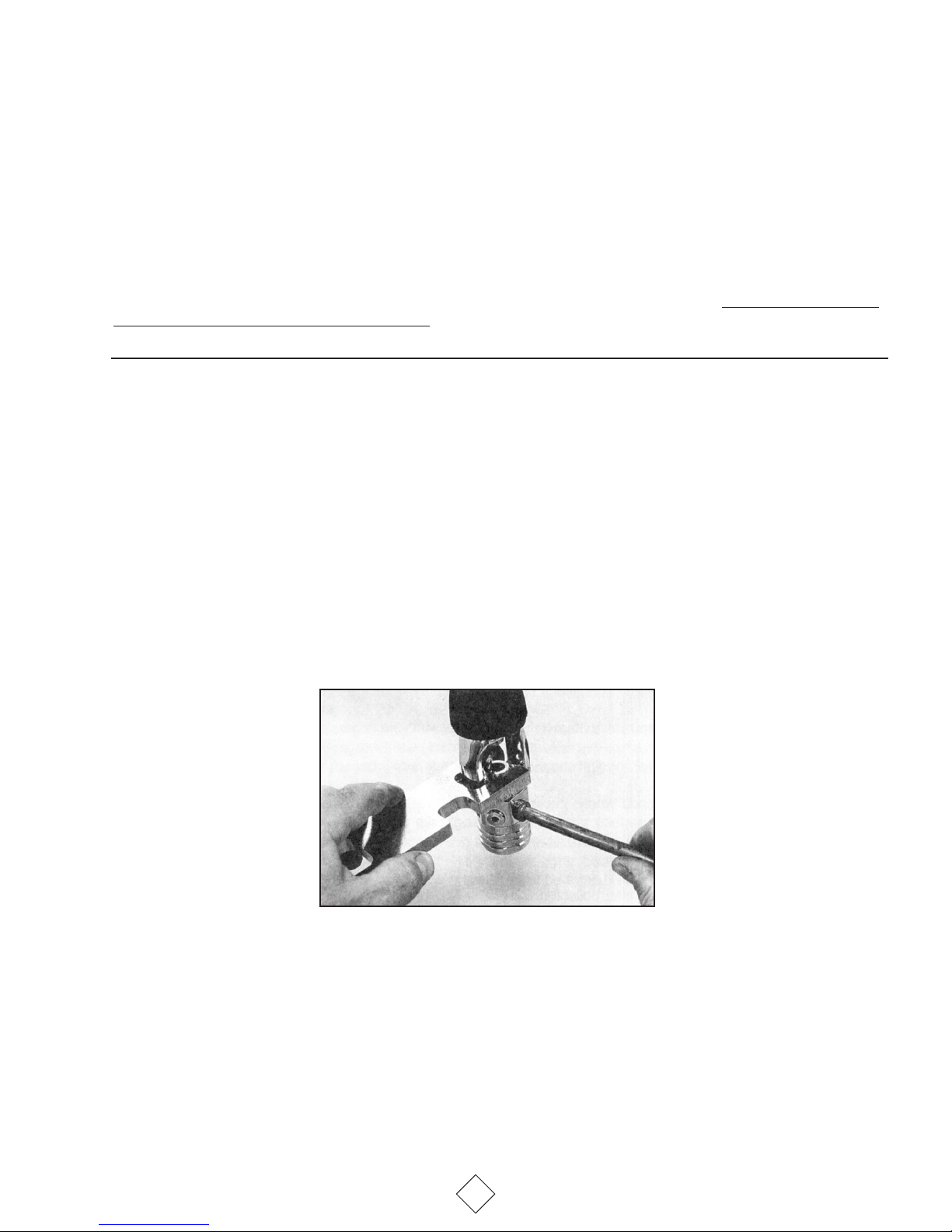
(4) Install a Sherwood regulator support handle (p/n TL113) into one of the low-pressure ports. Use the
support handle and a Sherwood combination wrench (p/n 9-TL101) or bench vise to loosen the yoke nut (Item 6)
from the body (Item 11). See Photo #1.
PHOTO
#1
NOTE: If a Sherwood DIN adaptor (p/n SAA5300) is installed in place of the normal yoke assembly, remove
it at this time. (See Sherwood Technical Bulletin #104 for servicing procedures for the SAA5300 DIN adaptor.)
(5) Remove the yoke (item 7) and yoke nut from the body.
(6) Use a 5/32" Allen wrench to remove all remaining port plugs (Items 9 & 13) from the body.
(7) Use a Sherwood regulator support handle (p/n TL113) and a 15" adjustable wrench or bench vise to
remove the cap (item 21) from the main body.
3
 Loading...