

Sharp XV-ZW99U Service Manual
I
xv-zw99u
SHARP
SERVICE MANUAL
SY8A9XV-ZW99U
LCD PROJECTOR
In the interests of user-safety (Required by safety regulations in some countries) the set should be restored
to its original condition and only parts identical to those specified should be used.
/
l SPECIFICATIONS .............................................. 2
l IMPORTANT SERVICE SAFETY NOTES. ......... 3
l NOTE TO SERVICE PERSONNEL.. .................. 4
l OPERATION MANUAL ...................................... 7
. REMOVING OF MAJOR PARTS.. .................... 12
l RESETTING THE LAMP TIMER.. .................... 17
l THE OPTICAL UNIT OUTLINE ........................ 18
l CONVERGENCEAND
FOCUS ADJUSTMENT .................................... 19
l ELECTRICAL ADJUSTMENT .......................... 23
l TROUBLE SHOOTING TABLE ........................ 29
l CHASSIS LAYOUT.. ......................................... 42
CONTENTS
Page
l OVERALL WIRING DIAGRAM AND
BLOCK DIAGRAM . . . . . . . . . . . . . . . . . . . . . . . . . . . . . . . . . . . . . . . . . . . 44
l DESCRIPTION OF SCHEMATIC DIAGRAM ..a. 46
l WAVEFORMS . . . . . . . . . . . . . . . . . . . . . . . . . . . . . . . . . . . . . . . . . . . . . . . . . . 47
l SCHEMATIC DIAGRAM . . . . . . . . . . . . . . . . . . . . . . . . . . . . . . . . . . . 48
. PRINTED WIRING BOARD ASSEMBLIES . . . . . . 88
l PARTS LIST
l PACKING OF THE SET . . . . . . . . . . . . . . . . . . . . . . . . . . . . . . . . . . 135
Page
n ELECTRICAL PARTS . . . . . . . . . . . . . . . . . . . . . . . . . . . . . . . . . 97
n CABlNETAND MECHANICAL PARTS..... 129
n ACCESSORIES PARTS . ..a....................... 134
n PACKING PARTS . . . . . . . . . . . . . . . . . . . . . . . . . . . . . . . . . . . . . . 134
SHARP CORPORATlON
This document has been published to be used for
after sales service only.
The contents are subject to change without notice.
xv-zw99u
1
Specifications
Product type
Model
Video system
Display method
LCD panel
Lens
Projection lamp
Brightness (ANSI lumen)
Contrast ratio
Video input signal
S-video input signal
Video (monitor) output signal
Component video input signal
Horizontal resolution
Audio output
Computer RGB input signal
RGB input signal
Speaker system
Rated voltage
Input current
Rated frequency
Power consumption
Operating temperature
Storage temperature
Cabinet
I/R Carrier frequency
Dimensions (approx.)
Weight (approx.)
Supplied accessories
Replacement parts
LCD Projector
xv-zw99u
NTSC 3.58
LCD panel x 3. RGB optical shutter method
Panel size: 1.3” (19.8 [H] x 26.4 [W] mm)
Display method: Translucent TN liquid crystal panel
Drive method: TFT (Thin Film Transistor) Active Matrix panel
No. of dots: 519,168 dots (832 [H] x 624 [VI)
1-1.6x zoom lens, F2.5-3.2, f = 48-76 mm
370 W Metal halide lamp
400 ANSI lumens (during RGB input and SVGA display)
1OO:l
RCA Connector: VIDEO, composite video, 1 .O Vp-p, sync negative, 75 R terminated
RCA Connector: AUDIO, 0.5 Vrms more than 22 kR (stereo)
4-pin mini DIN connector
Y (luminance signal): 1 .O Vp-p, sync negative, 75 R terminated
C (chrominance signal): Burst 0.286 Vp-p, 75 R terminated
RCA Connector: VIDEO. composite video, 1 .O Vp-p sync negative, 75 R terminated
RCA Connector: AUDIO, 0.5 Vrms more than 2.2 kR (stereo)
RCA Connector: Y (luminance signal): 1 ,O Vp-p, sync negative, 75 R terminated
PB (Ce) (chrominance signal): 0.7 Vp-p, 75 R terminated
PR (CR) (chrominance signal): 0.7 Vp-p, 75 R terminated
RCA Connector: AUDIO, 470 mVrms, more than 22 kR (stereo)
580 TV lines (video input)
3 W + 3 W (stereo)
video signal
15-PIN MINI D-SUa CONNECTOR (RGB Input Port):
RGB separate type analog input:
O-O.7 Vp-p, positive, 75 0 terminated
STEREO MINIJACK:
AUDIO, 0.5 Vrms, more than 22 kR (stereo)
HORIZONTAL SYNC. SIGNAL:
TTL level (positive/negative) or composite sync (Apple only)
VERTICAL SYNC. SIGNAL:
Same as above
g-pin D-sub male connector (RS-232C Input Port)
3 3%z” (8 cm) round x 2
AC 110-120 V
1.8 All .O A
50/60 Hz
500w
41°F to 104°F (+5”C to +4O”C)
- 4°F to 140°F ( - 20°C to + 60%)
Plastic
40 kHz
14 %” (W) x 7 %&4”(H) x 20 %z” (D) (359 x 195 x 528 mm) (projector only)
17 3%” (W) x 7 43/M” (H) x 20 %z” (D) (444 x 195 x 528 mm) (including terminal
cover)
30.8 Ibs. (14.0 kg)
Remote control, Four AA batteries, Computer (VGA) cable (9’ lo”, 3 m), Macintosh
adaptor, A/V cable, Extra air filter, Lens cap (attached), Power cord (9’ lo”, 3 m),
Terminal cover, Inverted labels, Lens shipping block
Remote control (RRMCG1461CESA), Computer (VGA) cable (QCNW-5050CEZZ),
Macintosh adaptor (QPLGJ1512CEZZ), AN cable (QCNW-3740CEZZ), Air filter
(PFILD0082CEZZ), Lens cap (PCAPH1049CESB), Power cord (QACCU5013CEZZ),
Terminal cover (GCOVA1690CEK/), Inverted labels (HINDP4946CESQ Lens shipping
block (SPAKX2842CEZZ)
This SHARP projector uses LCD (Liquid Crystal Display) panels.
These very sophisticated panels contain 519,168 pixels (X RGB)
TFk (Thin Film Transistors).
As with any high technology electronic equipment such as large
screen TVs, video systems and video cameras, there are certain
acceotable tolerances that the eauioment must conform to. This
unit his some inactive TFk with6 acceptable tolerances which
may result in illuminated or inactive dots on the picture screen.
Specifications are subject to change without notice
This will not affect the picture quality or the life expectancy of the
unit.
If you have any questions about this matter, please call toll free
1 -WI-BE-SHARP (l-800-237-4277). [u.s]
2
1 xv-zw99u
IMPORTANT SERVICE SAFETY NOTES
n Service work should be performed only by qualified service technicians who are
thoroughly familiar with all safety checks and servicing guidelines as follows:
WARNING
1. For continued safety, no modification of any circuit
should be attempted.
2. Disconnect AC power before servicing.
BEFORE RETURNING THE PROJECTOR:
(Fire & Shock Hazard)
Before returning the projector to the user, perform
the following safety checks:
1.
Inspect lead wires are not pinched between the
chassis and other metal parts of the projector.
Inspect all protective devices such as non-metallic
2.
control knobs, insulating materials, cabinet backs,
adjustment and compartment covers or shields,
isolation resistor-capacity networks, mechanical
insulators, etc.
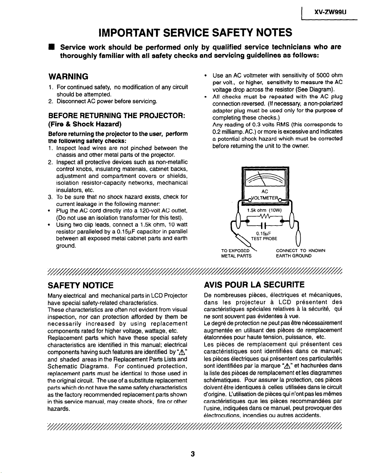
To be sure that no shock hazard exists, check for
3.
current leakage in the following manner:
.
Plug the AC cord directly into a 120~volt AC outlet,
(Do not use an isolation transformer for this test).
.
Using two clip leads, connect a 1 Sk ohm, 10 watt
resistor paralleled by a 0.15yF capacitor in parallel
between all exposed metal cabinet parts and earth
ground.
Use an AC voltmeter with sensitivity of 5000 ohm
per volt., or higher, sensitivity to measure the AC
voltage drop across the resistor (See Diagram).
All checks must be repeated with the AC plug
connection reversed. (If necessary, a non-polarized
adapter plug must be used only for the purpose of
completing these checks.)
Any reading of 0.3 volts RMS (this corresponds to
0.2 milliamp. AC.) or more is excessive and indicates
a potential shock hazard which must be corrected
before returning the unit to the owner.
METAL PARTS
EARTH GROUND
0 KNOWN
SAFETY NOTICE
Many electrical and mechanical parts in LCD Projector
have special safety-related characteristics.
These characteristics are often not evident from visual
inspection, nor can protection afforded by them be
necessarily increased by using replacement
components rated for higher voltage, wattage, etc.
Replacement parts which have these special safety
characteristics are identified in this manual; electrical
components having such features are identified by “8”
and shaded areas in the Replacement Parts Lists and
Schematic Diagrams. For continued protection,
replacement parts must be identical to those used in
the original circuit. The use of a substitute replacement
parts which do not have the same safety characteristics
as the factory recommended replacement parts shown
in this service manual, may create shock, fire or other
hazards.
L
AVIS POUR LA SECURITE
De nombreuses pieces, electriques et mecaniques,
dans les projecteur a LCD presentent des
caracteristiques speciales relatives a la securite, qui
ne sont souvent pas evidentes a vue.
Le degre de protection ne peut pas Qtre necessairement
augmentee en utilisant des pieces de remplacement
etalonnees pour haute tension, puissance, etc.
Les pieces de remplacement qui presentent ces
caracteristiques sont identifiees dans ce manuel;
les pieces electriques qui presentent ces particularites
sont identifiees par la marque “A” et hachurees dans
la liste des pieces de remplacement et les diagrammes
schematiques. Pour assurer la protection, ces pieces
doivent Qtre identiques a celles utilisees dans le circuit
d’origine. L’utilisation de pieces qui n’ont pas les memes
caracteristiques que les pieces recommandees par
I’usine, indiquees dans ce manuel, peut provoquer des
electrocutions, incendies ou autres accidents.
3
xv-zw99u
I
NOTE TO SERVICE
PERSONNEL
UV-RADIATION PRECAUTION
k
The light source, metal halide lamp, in the LCD
projector emits small amounts of UV-Radiation.
AVOID DIRECT EYE AND SKIN
EXPOSURE.
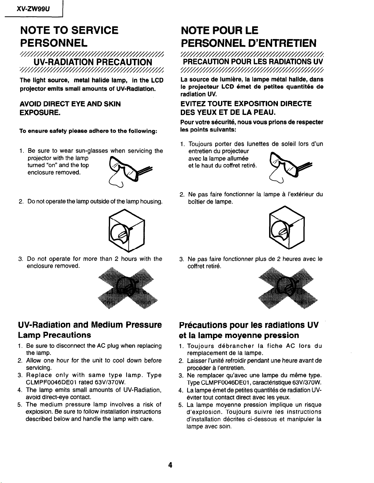
To ensure safety please adhere to the following:
1. Be sure to wear sun-glasses when servicing the
projector with the lamp
turned “on” and the top
enclosure removed.
2. Do not operate the lamp outside of the lamp housing.
NOTE POUR LE
PERSONNEL D’ENTRETIEN
Y
PRECAUTION POUR LES RADIATIONS UV
‘///////////////////
La source de lumiere, la lampe metal halide, dans
le projecteur LCD 6met de petites quantites de
radiation UV.
EVITEZ TOUTE EXPOSITION DIRECTE
DES YEUX ET DE LA PEAU.
Pour votre securite, nous vous prions de respecter
les points suivants:
Toujours porter des lunettes de soleil lors d’un
1.
entretien du projecteur
avec la lampe allumee
et le haut du coffret retire.
Ne pas faire fonctionner la lampe a I’exterieur du
2
boitier de lampe.
*P
/
?Y@
3. Do not operate for more than 2 hours with the
enclosure removed.
UV-Radiation and Medium Pressure
Lamp Precautions
Be sure to disconnect the AC plug when replacing
1.
the lamp.
Allow one hour for the unit to cool down before
2.
servicing.
Replace only with same type lamp. Type
3.
CLMPF0046DEOl rated 63V/37OW.
4.
The lamp emits small amounts of UV-Radiation,
avoid direct-eye contact.
The medium pressure lamp involves a risk of
5.
explosion. Be sure to follow installation instructions
described below and handle the lamp with care.
Ne pas faire fonctionner plus de 2 heures avec le
3.
coff ret retire.
Prkautions pour les radiations UV
et la lampe moyenne pression
1.
Toujours debrancher la fiche AC lors du
remplacement de la lampe.
Laisser I’unite refroidir pendant une heure avant de
2.
proceder a I’entretien.
Ne remplacer qu’avec une lampe du mQme type.
3.
Type CLMPF0046DE01, caracteristique 63V/37OW.
La lampe emet de petites quantites de radiation UV-
4.
dviter tout contact direct avec les yeux.
La lampe moyenne pression implique un risque
5.
d’explosion. Toujours suivre les instructions
d’installation d&rites ci-dessous et manipuler la
lampe avec soin.
xv-zw99u
////////////////////
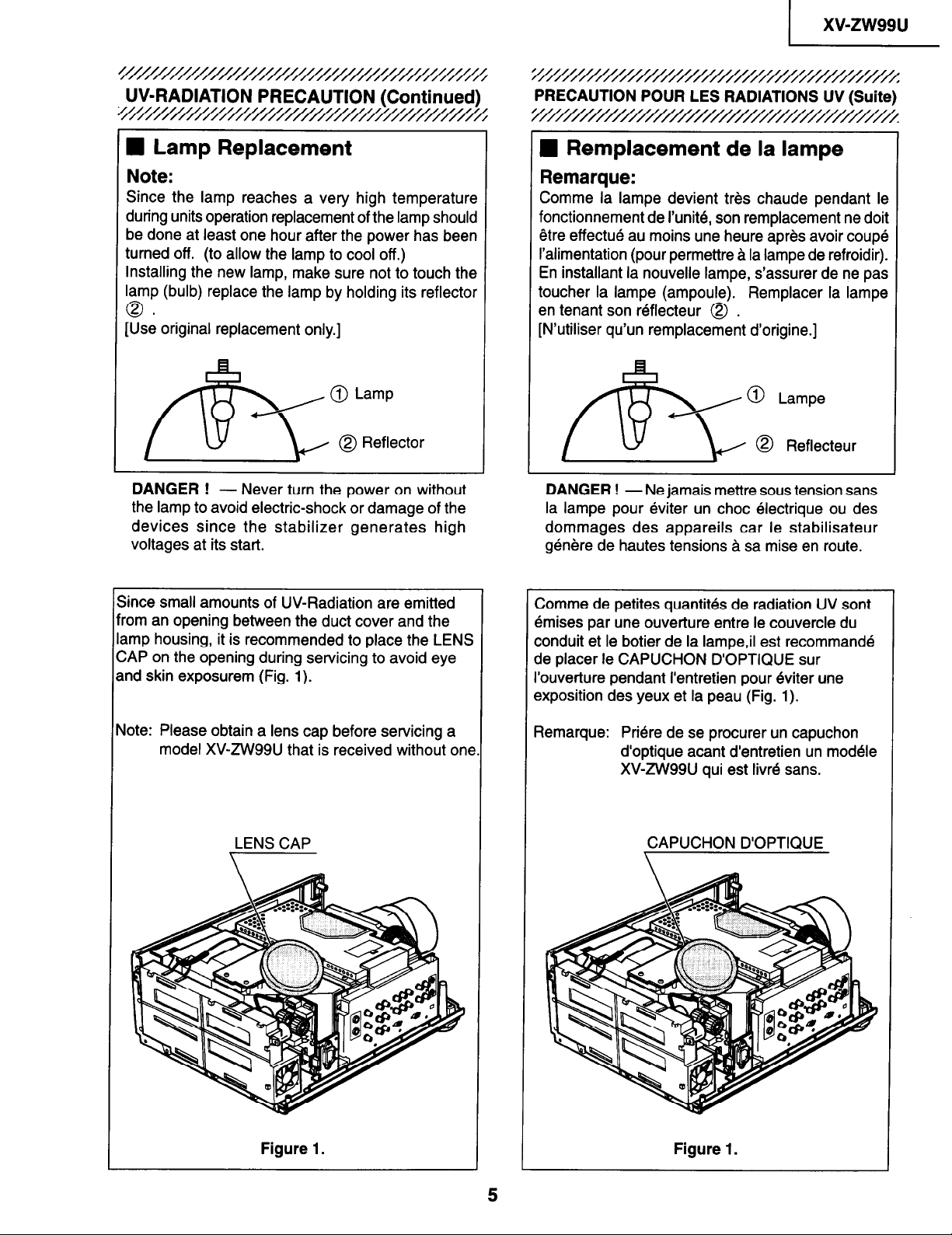
UV-RADIATION PRECAUTION (Continued)
1
n Lamp Replacement
Note:
Since the lamp reaches a very high temperature
during units operation replacement of the lamp should
be done at least one hour after the power has been
turned off. (to allow the lamp to cool off.)
Installing the new lamp, make sure not to touch the
lamp (bulb) replace the lamp by holding its reflector
0.
[Use original replacement only.]
@ Lamp
@ Reflector
f&5
DANGER !
the lamp to avoid electric-shock or damage of the
devices since the stabilizer generates high
voltages at its start.
- Never turn the power on without
v
PRECAUTION POUR LES RADIATIONS UV (Suite)
9
I Remplacement de la lampe
Remarque:
Comme la lampe devient tres chaude pendant le
fonctionnement de I’unite, son remplacement ne doit
etre effectue au moins une heure apres avoir coupe
I’alimentation (pour permettre a la lampe de refroidir).
En installant la nouvelle lampe, &assurer de ne pas
toucher la lampe (ampoule). Remplacer la lampe
en tenant son reflecteur @ .
[N’utiliser qu’un remplacement d’origine.]
0 Lampe
&
DANGER ! - Ne jamais mettre sous tension sans
la lampe pour eviter un choc electrique ou des
dommages des appareils car le stabilisateur
genere de hautes tensions a sa mise en route.
0 Reflecteur
Since small amounts of UV-Radiation are emitted
‘ram an opening between the duct cover and the
amp housing, it is recommended to place the LENS
ZAP on the opening during servicing to avoid eye
and skin exposurem (Fig. 1).
\lote: Please obtain a lens cap before servicing a
model XV-ZW99U that is received without one
LENS CAP
Comme de petites quantites de radiation UV sont
emises par une ouverture entre le couvercle du
conduit et le botier de la lampe,il est recommande
de placer le CAPUCHON D’OPTIQUE sur
I’ouverture pendant I’entretien pour dviter une
exposition des yeux et la peau (Fig. 1).
Remarque:
Priere de se procurer un capuchon
d’optique acant d’entretien un modele
XVZW99U qui est livre sans.
CAPUCHON D’OPTIQUE
Figure 1.
Figure 1.
5
xv-zw99u
I
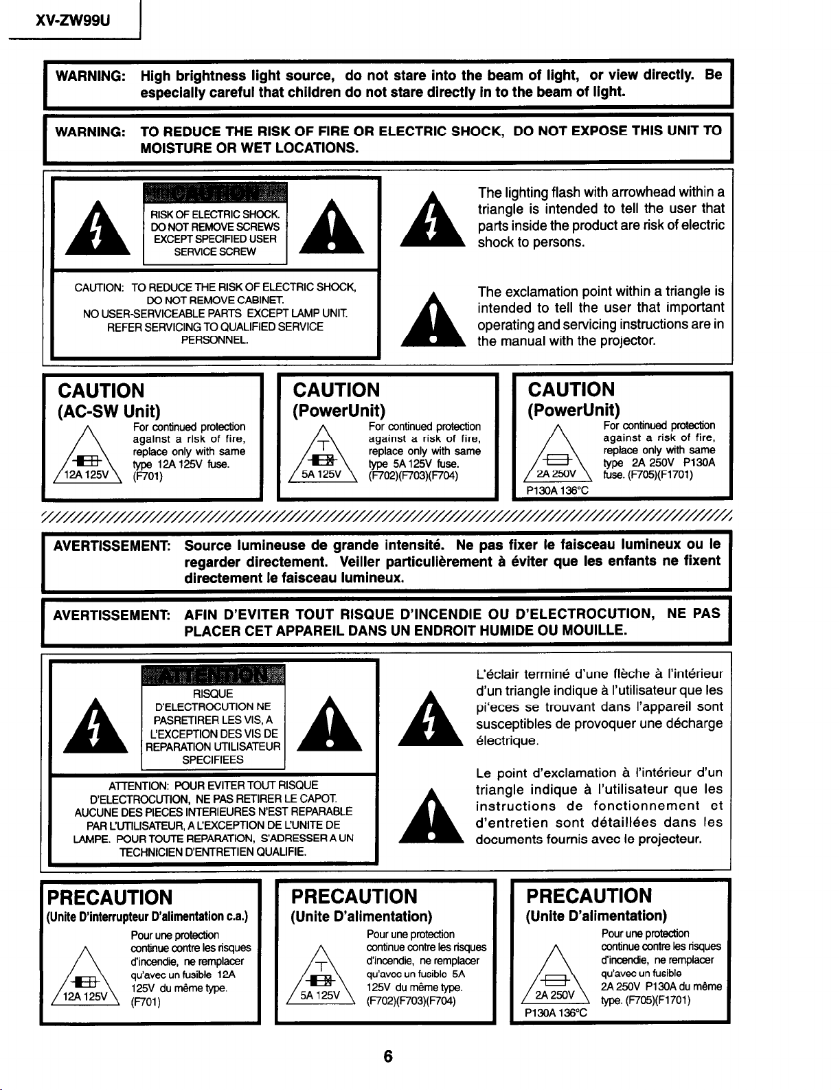
WARNING- High brightness light source,
-
WARNING: TO REDUCE THE RISK OF FIRE OR ELECTRIC SHOCK, DO NOT EXPOSE THIS UNIT TO
I
CAUTION: TO REDUCE THE RISK OF ELECTRIC SHOCK,
NO USER-SERVICEABLE PARTS EXCEPT LAMP UNIT.
CAUTION
(AC-SW Unit)
especially careful that children do not stare directly in to the beam of light.
MOISTURE OR WET LOCATIONS.
DO NOT REMOVE CABINET
REFER SERVICING TO QUALIFIED SERVICE
PERSONNEL.
CAUTION
(PowerUnit)
For continued protection
against a risk of fire,
replace only with same
type 12A125V fuse.
(no1 )
do not stare into the beam of light, or view directly. Be
The lighting flash with arrowhead within a
triangle is intended to tell the user that
parts inside the product are risk of electric
A
A
shock to persons.
The exclamation point within a triangle is
intended to tell the user that important
operating and servicing instructions are in
the manual with the projector.
CAUTION
For continued protection
against a risk of fire,
replace only with same
type 5A 125V fuse.
(F7’02)(F703)(F704)
(PowerUnit)
2A 250v
A
P13OA 136°C
For continued protection
against a risk of fire,
replace only with same
type 2A 250V P13OA
fuse. (F705)(F1701)
I
I
AVERTISSEMENT: Source lumineuse de grande intensitk
regarder directement. Veiiler particulkement a 6viter que les enfants ne fixent
directement ie faisceau lumineux.
AVERTISSEMENT: AFIN D’EVITER TOUT RISQUE D’INCENDIE OU D’ELECTROCUTION, NE PAS
PLACER CET APPAREIL DANS UN ENDROIT HUMIDE OU MOUILLE.
D’ELECTROCUTION NE
PASRETIRER LES VIS, A
CEXCEPTION DES VIS DE
A
D’ELECTROCUTION, NE PAS RETIRER LE CAPOT.
AUCUNE DES PIECES INTERIEURES N’EST REPARABLE
PAR CUTlLISATEUR, A CEXCEPTION DE CUNITE DE
LAh,lPE. POUR TOUTE REPARATION, S’ADRESSER A UN
REPARATION UTILISATEUR
SPECIFIEES
ATTENTION: POUR EVITER TOUT RISQUE
TECHNICIEN D’ENTRETIEN QUALIFIE.
A
A
A
Ne pas fixer le faisceau lumineux ou ie
L’&lair termin d’une fi&che A I’interieur
d’un triangle indique A I’utilisateur que les
pi‘eces se trouvant dans I’appareil sont
susceptibles de provoquer une d6charge
klectrique.
Le point d’exclamation A I’interieur d’un
triangle indique A I’utilisateur que les
instructions de fonctionnement et
d’entretien sont d6tailEes dans les
documents fournis avec le projecteur.
I1
PRECAUTION
Unite DTnterrupteur D’alimentation c.a.)
Pour uns probction
continue c0ntre les risques
d’incendie, ne remplacer
qu’avec un fusible 12A
125V du m6me lype.
(no1 1
PRECAUTION
(Unite D’alimentation)
Pour une protection
continue contre les risques
d’incendie, ne remplacer
qu’avec un fusible 5A
125V du m&me type.
(F702)(F703)(F704)
PRECAUTION
(Unite D’alimentation)
Pour une protection
continue contre les risques
d’incendii, ne remplacer
qu’avec un fusible
2A 250v
/4
P13OA 136°C
2A 250V P13OA du mdme
type. (F705)(F1701)
6

1
Location of Controls
For details on the use of each control and terminal, refer to the page number indicated in the brackets.
Projector
POWER button (ON/OFF)
Speakers
POWER indicator
LAMP REPLACEMENT
indicator
TEMPERATURE WARNING
Cooling fan (Intake vent)
Cooling fan
(Exhaust vent)
Carrying handle
Lamp cage cover
(Natural ventilation)
Adjuster release
F indicator
Remote control sensor
xv-zw99u
S-VIDEO INPUT 1
terminal: 4-pin mini DIN
VIDEO INPUT 2 terminal:
S-VIDEO INPUT 2
terminal: 4-pin mini DIN
MAIN POWER switch
ENTER button
ANALOG COMPONENT
AUDIO INPUT 1 terminals: AUDIO INPUT 1 terminals:
ANALOG COMPONENT
AUDIO INPUT 2
RGB AUDIO INPUT
terminal (3.5 mm stereo
DC 12V200mA
OUTPUT terminal
2C port (g-pin D-sub)
COMPONENT VIDEO
RCA
AUDIO INPUT 2 terminals: RGB INPUT port
RCA
INOrr
l If a current of 200 mA or more is drawn from the DC 12 V OUTPUT terminal, a protection device will automatically stop
output from the projector.
(HD-15)
terminals: RCA
7
xv-zw99u
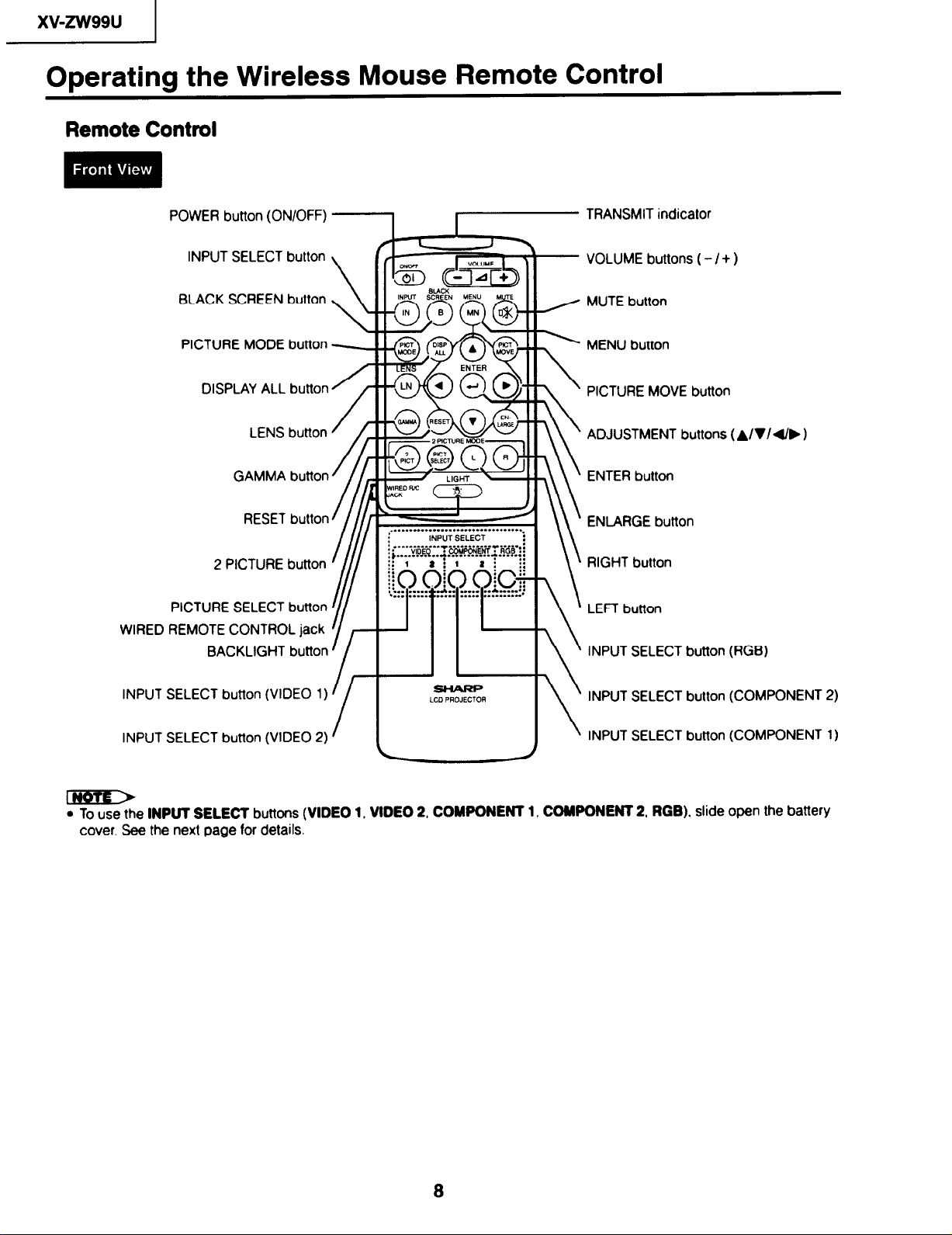
Operating the Wireless Mouse Remote Control
Remote Control
POWER button (ON/OFF)
INPUT SELECT button
BLACK SCREEN button
PICTURE MODE button -
DISPLAY ALL button
LENS button
GAMMA button
RESET button
2 PICTURE button
PICTURE SELECT button
WIRED REMOTE CONTROL jack
BACKLIGHT button
TRANSMIT indicator
- VOLUME buttons ( - / + )
/ MUTE button
’ MENU button
\
\ ’ PICTURE MOVE button
ADJUSTMENT buttons (A/V/d//, 1
ENTER button
ENLARGE button
\ RIGHT button
\
LEFT button
\
INPUT SELECT button (RGB)
\
INPUT SELECT button (VIDEO 1)
INPUT SELECT button (VIDEO 2)
l To use the INPUT SELECT buttons (VIDEO 1, VIDEO 2, COMPONENT 1, COMPONENT 2, RGB). slide open the battery
cover. See the next page for details.
INPUT SELECT button (COMPONENT 2)
\
INPUT SELECT button (COMPONENT 1)
a
I
@
t
Battery
cover
xv-zw99u
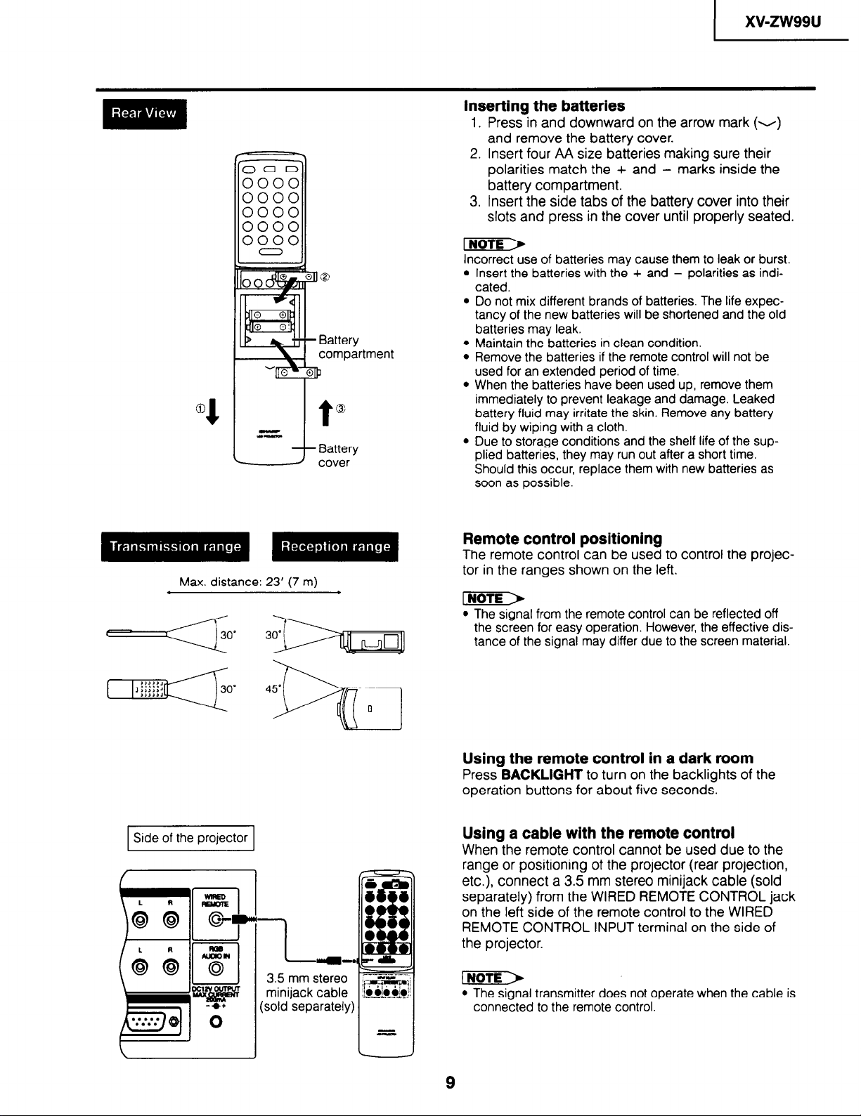
Inserting the batteries
1. Press in and downward on the arrow mark (v)
and remove the battery cover.
2. Insert four AA size batteries making sure their
polarities match the + and - marks inside the
battery compartment.
3. Insert the side tabs of the battery cover into their
slots and press in the cover until properly seated.
Incorrect use of batteries may cause them to leak or burst.
Insert the batteries with the + and - polarities as indicated.
Do not mix different brands of batteries. The life expectancy of the new batteries will be shortened and the old
batteries may leak.
Maintain the batteries in clean condition.
Remove the batteries if the remote control will not be
used for an extended period of time.
When the batteries have been used up, remove them
immediately to prevent leakage and damage. Leaked
battery fluid may irritate the skin. Remove any battery
fluid by wiping with a cloth.
Due to storage conditions and the shelf life of the supplied batteries, they may run out after a short time.
Should this occur, replace them with new batteries as
soon as possible.
Max. distance: 23’ (7 m)
1 Side of the projector 1
-L
3.5 mm stereo
minijack cable
(sold-separately)
ml-
Remote control positioning
The remote control can be used to control the projector in the ranges shown on the left.
. The signal from the remote control can be reflected off
the screen for easy operation. However, the effective distance of the signal may differ due to the screen material.
Using the remote control in a dark room
Press BACKLIGHT to turn on the backlights of the
operation buttons for about five seconds.
Using a cable with the remote control
When the remote control cannot be used due to the
range or positioning of the projector (rear projection,
etc.), connect a 3.5 mm stereo minijack cable (sold
separately) from the WIRED REMOTE CONTROL jack
on the left side of the remote control to the WIRED
REMOTE CONTROL INPUT terminal on the side of
the projector.
INoTE)
l The signal transmitter does not operate when the cable is
connected to the remote control.
xwzw99u
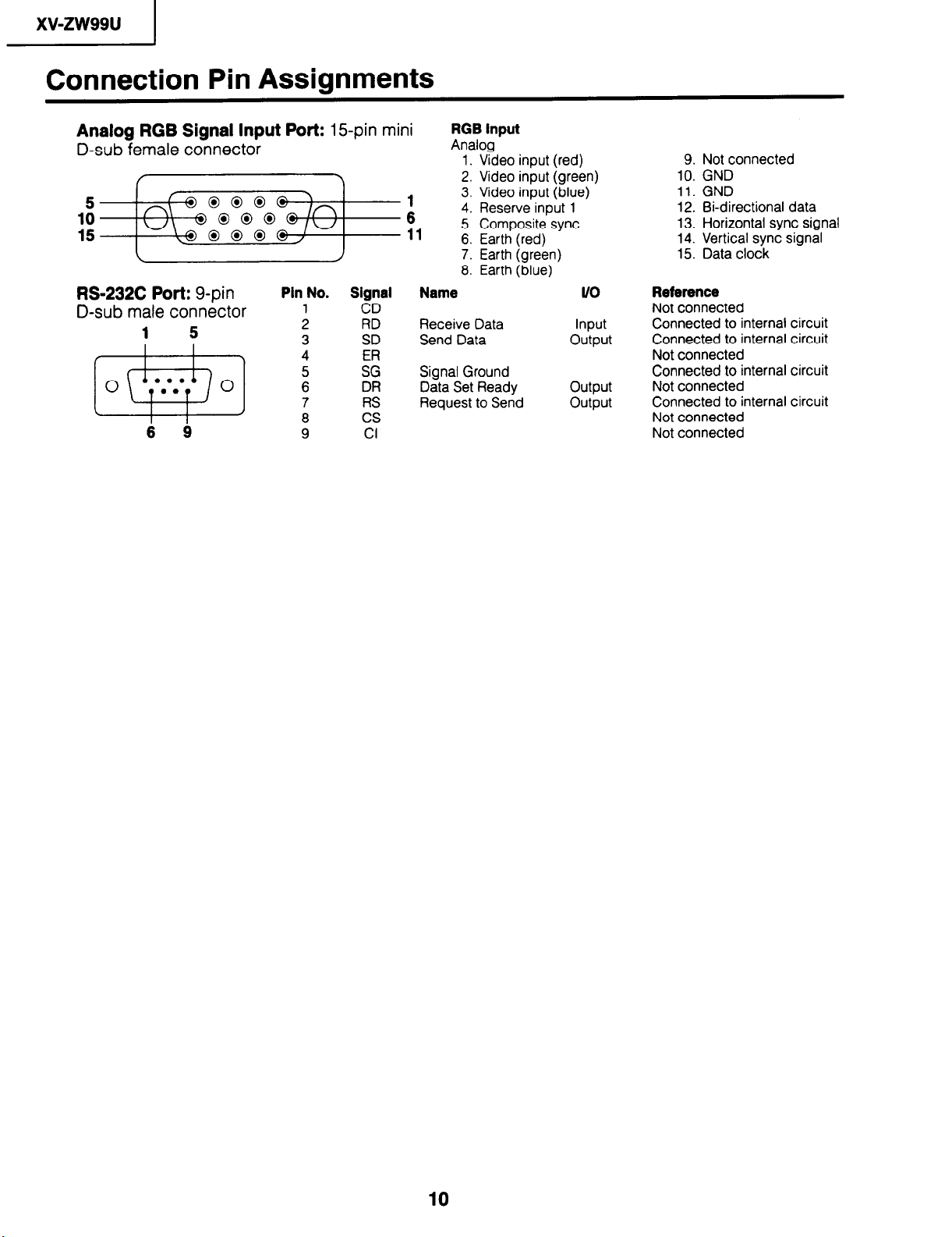
Connection Pin Assignments
Analog RGB Signal Input Port: 15-pin mini
D-sub female connector
f Y
\ / 7. Earth (green)
RS-232C Port: g-pin
D-sub male connector
1 5 2 Receive Data Input
6 g 9 Cl
Pin No. Signal Name It0
1
3 z:: Send Data output
4 5 :: Signal Ground
CD
6 DR Data Set Ready output
RS Request to Send output
;
cs
RGB input
Analog
1. Video input (red)
2. Video input (green)
3. Video input (blue)
4. Reserve input 1
5. 15 +z 0 0 0 @, 11 Composite sync
6. Earth (red)
6. Earth (blue)
9. Not connected
10. GND
11. GND
12. B-directional data
13. Horizontal sync signal
14. Vertical sync signal
15. Data clock
Reference
Not connected
Connected to internal circuit
Connected to internal circuit
Not connected
Connected to internal circuit
Not connected
Connected to internal circuit
Not connected
Not connected
10
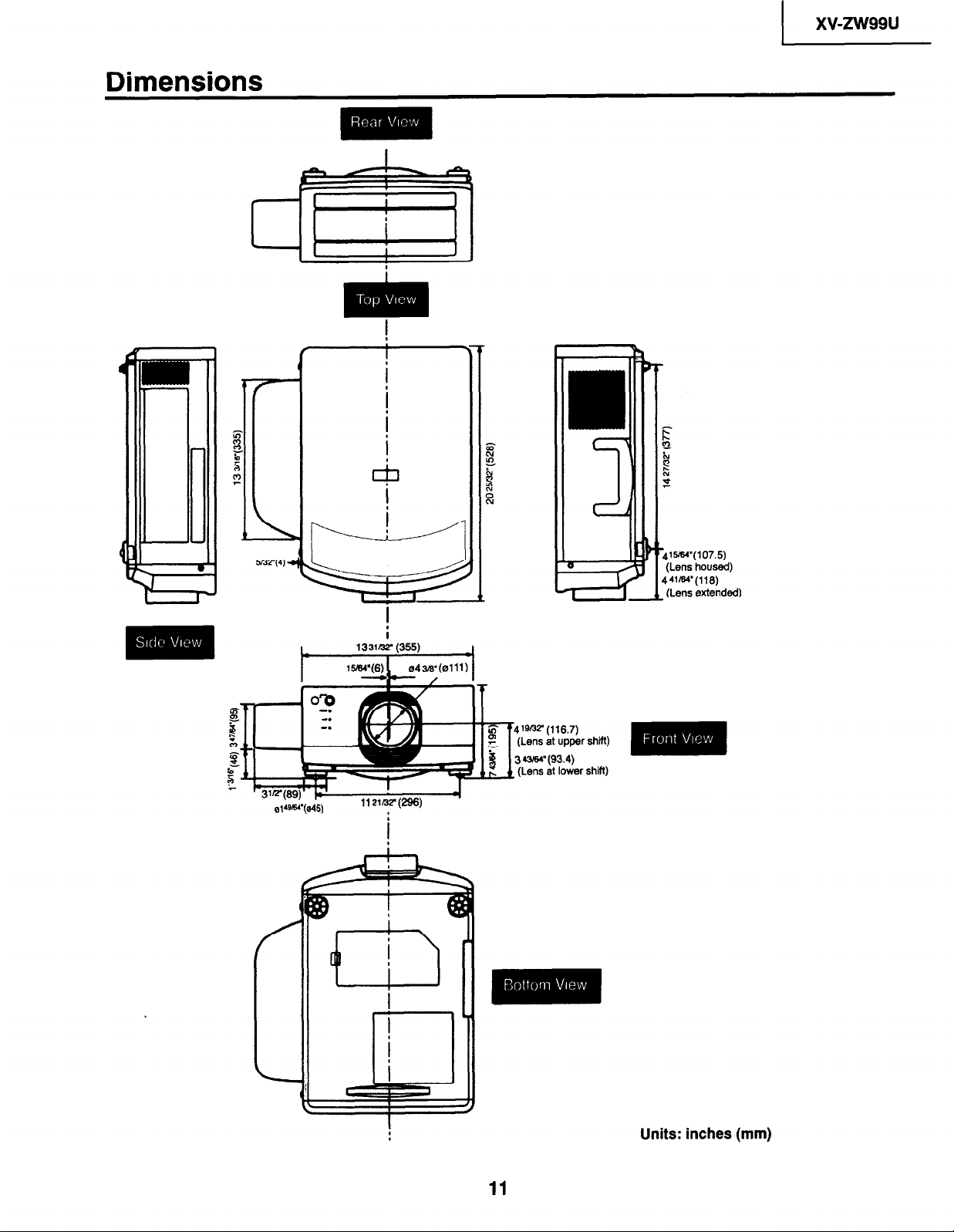
Dimensions
1
5my4) a
1~37.. (116.7)
Lens at upper shift)
4!%64” (93.4)
Lens at lower shift)
11
Units: inches (mm)
xv-m99u
I
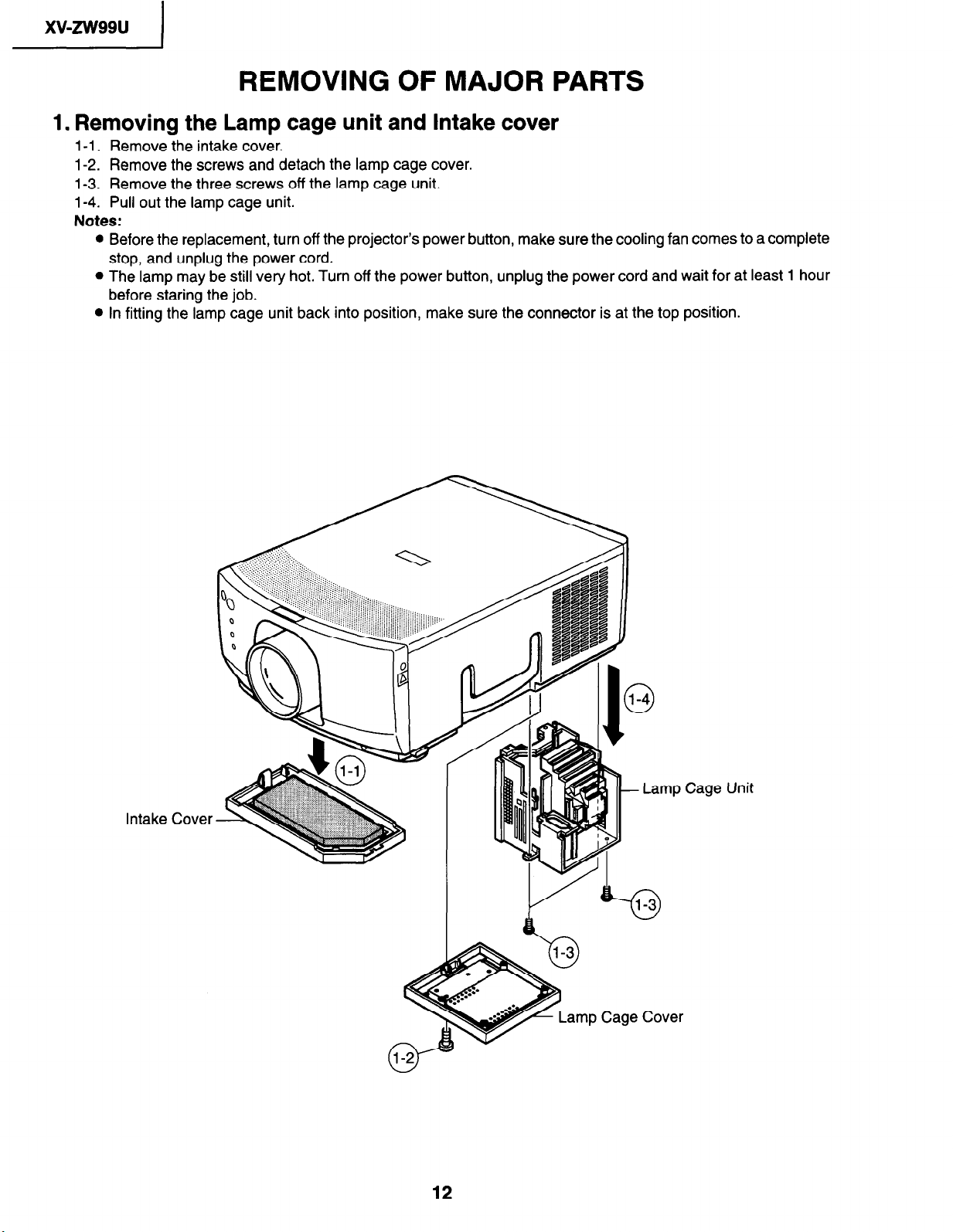
REMOVING OF MAJOR PARTS
1. Removing the Lamp cage unit and Intake cover
l-l. Remove the intake cover.
l-2. Remove the screws and detach the lamp cage cover.
l-3. Remove the three screws off the lamp cage unit.
l-4. Pull out the lamp cage unit.
Notes:
l Before the replacement, turn off the projector’s power button, make sure the cooling fan comes to a complete
stop, and unplug the power cord.
l The lamp may be still very hot. Turn off the power button, unplug the power cord and wait for at least 1 hour
before staring the job.
l In fitting the lamp cage unit back into position, make sure the connector is at the top position.
Intake Cover
12
Cage
Unit
1 xwzw99u
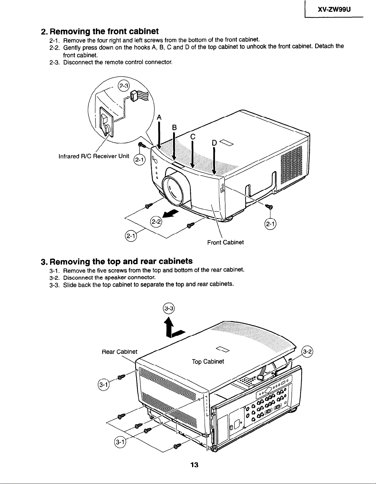
2. Removing the front cabinet
2-l.
Remove the four right and left screws from the bottom of the front cabinet.
2-2. Gently press down on the hooks A, B, C and D of the top cabinet to unhook the front cabinet. Detach the
front cabinet.
2-3. Disconnect the remote control connector.
3. Removing the top and rear cabinets
3-1. Remove the five screws from the top and bottom of the rear cabinet.
3-2.
Disconnect the speaker connector.
3-3. Slide back the top cabinet to separate the top and rear cabinets.
xv-m99u
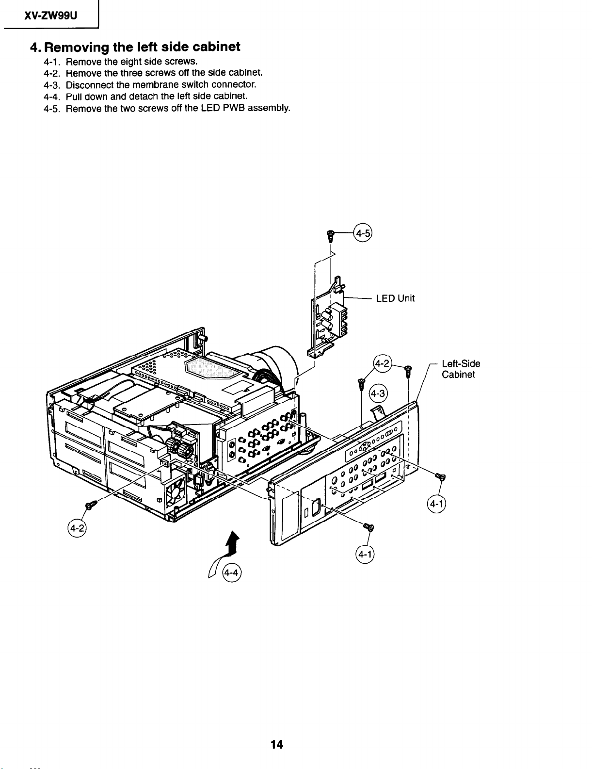
4. Removing the left side cabinet
4-1. Remove the eight side screws.
4-2. Remove the three screws off the side cabinet.
4-3. Disconnect the membrane switch connector.
4-4. Pull down and detach the left side cabinet.
4-5. Remove the two screws off the LED PWB assembly.
14
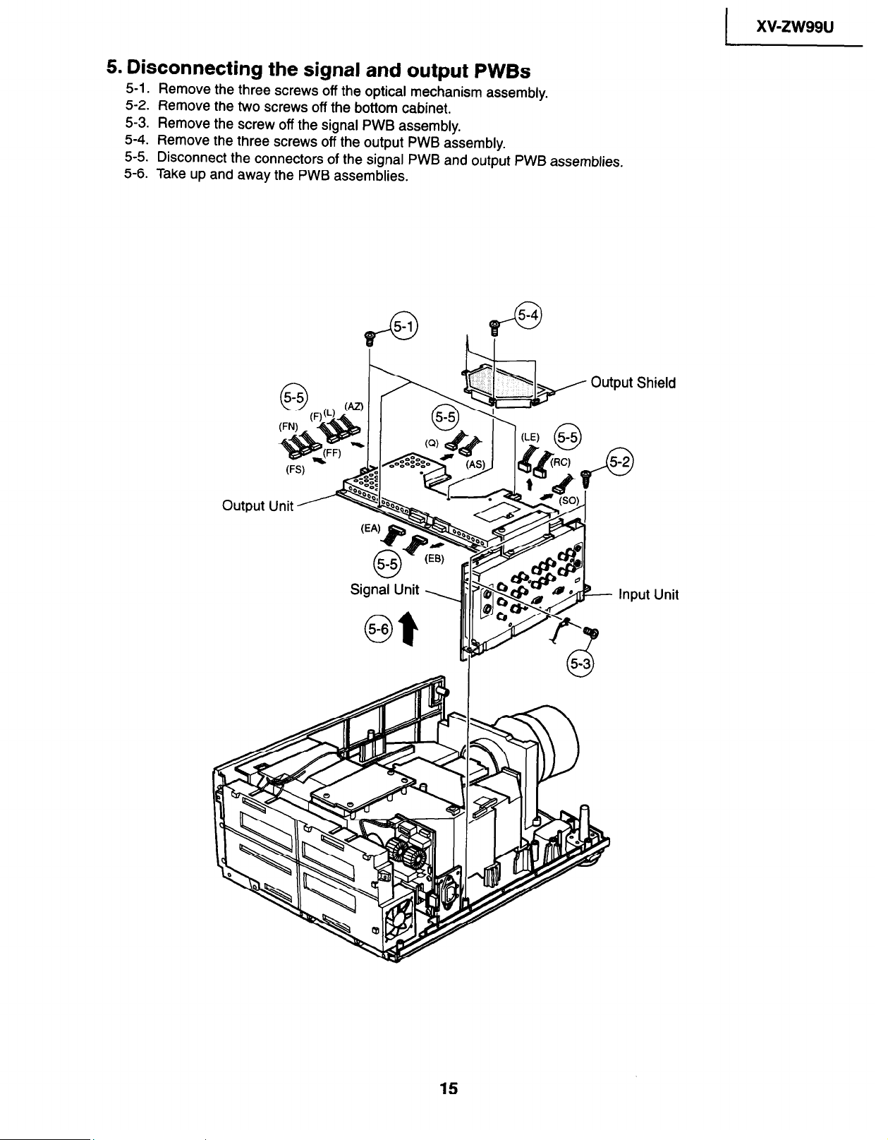
5. Disconnecting the signal and output PWBs
5-l. Remove the three screws off the optical mechanism assembly.
5-2. Remove the two screws off the bottom cabinet.
5-3. Remove the screw off the signal PWB assembly.
5-4. Remove the three screws off the output PWB assembly.
5-5. Disconnect the connectors of the signal PWB and output PWB assemblies.
5-6. Take up and away the PWB assemblies.
1 xwzw99u
15
1
xv-zw99u
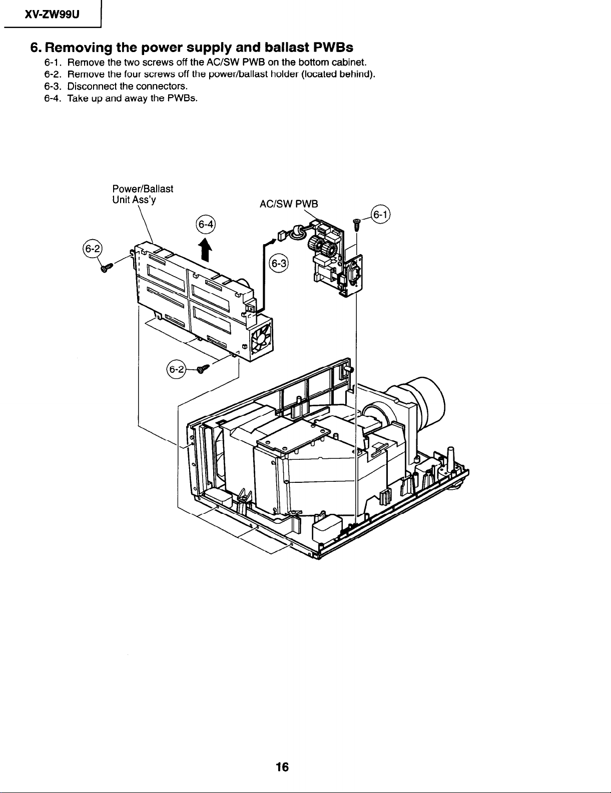
6. Removing the power supply and ballast PWBs
6-1. Remove the two screws off the AC/SW PWB on the bottom cabinet.
6-2. Remove the four screws off the power/ballast holder (located behind).
6-3. Disconnect the connectors.
6-4. Take up and away the PWBs.
Power/Ballast
Unit A\ss’y
AC/SW PWB
6-l
I&
16
I
xv-zw99u
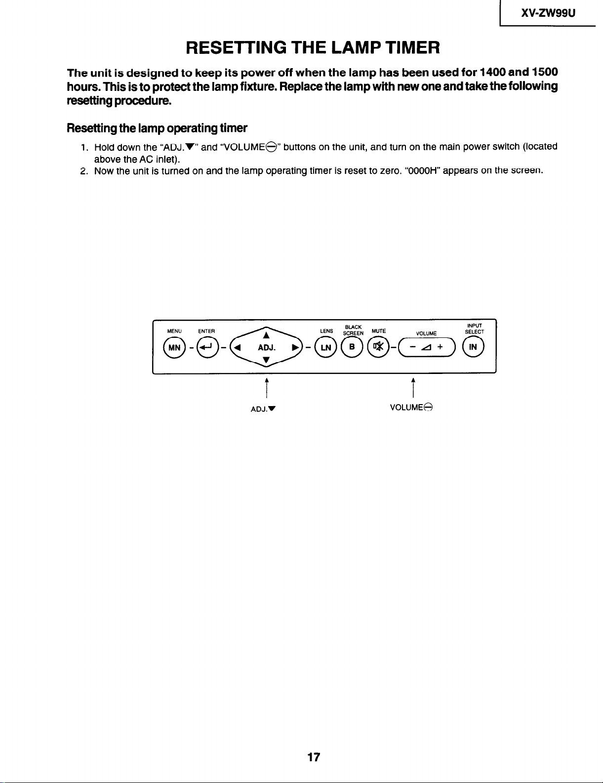
RESElTlNG THE LAMP TIMER
The unit is designed to keep its power off when the lamp has been used for 1400 and 1500
hours. This is to protect the lamp fixture. Replace the lamp with new one and take the following
resetting procedure.
Resetting the lamp operating timer
1. Hold down the “ADJ.W’ and “VOLUME@” buttons on the unit, and turn on the main power switch (located
above the AC inlet).
2. Now the unit is turned on and the lamp operating timer is reset to zero. “OOOOH” appears on the screen.
1
T
ADJ.v
T
VOLUME@
I
17
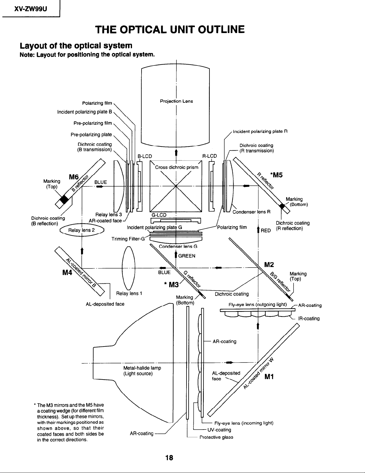
THE OPTICAL UNIT OUTLINE
Layout of the optical system
Note: Layout for positioning the optical system.
r-l-l
Polarizing film
Incident polarizing plate B
Pre-polarizing film
Pre-polarizing plate
Dichroic coating
(B transmission)
I
Projection Lens
Incident polarizing plate R
Dichroic coating
transmission)
Dichroic coating
(B -.
I AR-coated face
Y
AL-deposited face
Relay lens 1
I
Dichroic coating
RED (R reflection)
Fly-eye lens (bUtgOing light) - AR-coating
‘w I R-coating
Metal-halide lamp
(Light source)
l The M3 mirrors and the M5 have
a coating wedge (for different film
thickness). Set up these mirrors,
with their markings positioned as
shown above, so that their
coated faces and both sides be
in the correct directions.
AR-coating 1
18
- Fly-eye lens (incoming light)
- UV-coating
l-
Protective glass
xv-zw99u
CONVERGENCE AND FOCUS ADJUSTMENT
l Start the convergence and focus adjustments with the top cabinet and the signal
shield removed but the power on. Use the remote control to adjust the image. Take the
following procedures.
1. Focusing the projection lens
(A) Replacing all the 3 LCD panels
1. Before replacing all the 3 LCD panels, project an image on the screen and bring it into focus.
2. Replace the panels with new ones. But until the focus has been completely readjusted, be careful not to
change the distance between the set and the screen, nor to move the projection lens focus and zoom
rings.
If the focus is readjusted with a different positional relation, the relation between the projection distance
and the screen size is affected. In other words, a short-distance image (40 WIDE, for example) may
get out of the focus range, or a long-distance image (300 WIDE, for example) may come out of focus.
(B) Replacing 1 or 2 of the 3 LCD panels
1. In adjusting the focus after replacement of one or two LCD panels, project an image on the screen and
turn the projection lens focus ring to get the non-replaced LCD panel into focus.
2. But until the focus has been completely adjusted for the new LCD panels, be careful not to change the
distance between the set and the screen, nor to move the projection lens focus and zoom rings.
(If the distance has been changed or the projection lens readjusted, repeat the above steps 1 and 2.)
2. Adjusting the G-LCD panel
(A) Focus adjustment. (Make this adjustment on the white-only screen.)
1. Right-and-left focus adjustment (r3Y direction) .
Loosen the lock screws “b” and “c” and insert the eccentric screwdriver into the notch and hole “b” or “c”.
Turn the screwdriver until the right and left halves on the screen get into focus.
First get the right and left halves in balance. Then improve the accuracy while making the adjustment
2 below.
2. Top-center-bottom focus adjustment (OX and Z directions).
Loosen the lock screws “a” and “b” and insert the eccentric screwdriver into the notch and hole “a”. Turn
the screwdriver until the top, center and bottom on the screen get into focus.
bottom focus, temporarily tighten the lock screw “b” to fix the 8Y direction adjustment.
3. Repeat the above steps 1 and 2 to finely adjust the focus. Finally tighten up all the lock screws.
Notes :
@ Carefully proceed with the focus adjustment because the adjusting directions are correlated.
@ In adjusting the convergence and focus, do not move the projection lens zoom and focus rings until the
end of all the adjustments.
(B) Convergence adjustment
l The G-LCD panel has no convergence adjustment mechanism. Use this panel as convergence adjustment
reference.
3. B-LCD panel adjustment (the same for the R-LCD panel)
(A) Focus adjustment
l Take the same procedure as for the G-LCD panel focus adjustment. Note that the adjustment range is
small in the Z direction. If the convergence is quite different between the B-LCD and G-LCD panels,
roughly adjust the convergence first and then the focus.
(B) Convergence adjustment
l Use a crosshatch pattern signal for this adjustment.
Make the adjustment just for the G-color and the relevant color.
Loosen the convergence lock screw “d”.
(1)
With the G-LCD panel’s screen center as reference, adjust the B-LCD panel in the X, Y and 8Z directions.
(2)
Finally tighten up the convergence lock screw “d”.
(3)
1
In adjusting this top-to-
19
xv-zw99u
I
Notes :
The eccentric cam is used for convergence adjustment. This means that the cam’s turning and the linear
0
movement are not always uniform.
This model is not equipped with the LCD image adjustment mechanism. This is because the dichroic
0
prism is used for image formation. When the LCD panels all get into the best focus, the images are
almost completely converged.
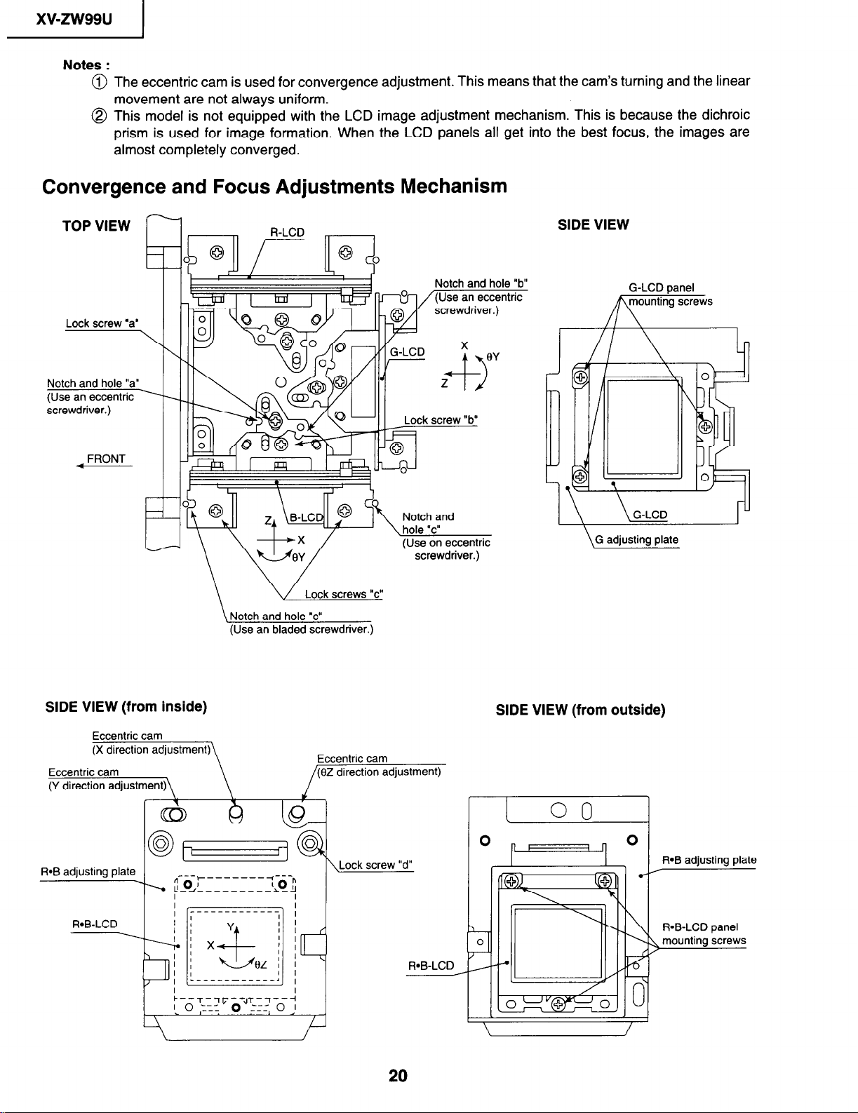
Convergence and Focus Adjustments Mechanism
SIDE VIEW
G-LCD panel
/yys
Notch and hole “a”
(Use an eccentric
screwdriver.)
FRONT
SIDE VIEW (from inside)
Eccentric cam
IJ
“b”
(Use an bladed screwdriver.)
SIDE VIEW (from outside)
Eccentric cam
(f3Z direction adjustment)
\Lock screw “d”
R-B-LCD
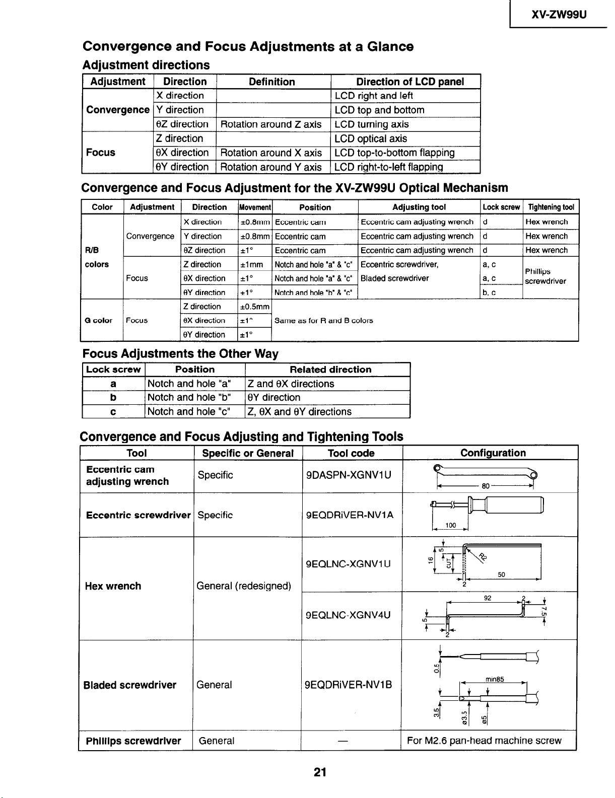
Convergence and Focus Adjustments at a Glance
Adjustment directions
Adjustment
Convergence Y direction
Focus
Convergence and Focus Adjustment for the XV-ZW99U Optical Mechanism
Direction Definition Direction of LCD panel
X direction
LCD right and left
LCD top and bottom
6Z direction Rotation around Z axis LCD turning axis
Z direction
LCD optical axis
8X direction Rotation around X axis LCD top-to-bottom flapping
8Y direction Rotation around Y axis LCD right-to-left flapping
xv-zw99u
Color Adjustment Direction
X direction
Convergence Y direction
WB BZ direction *la Eccentric cam Eccentric cam adjusting wrench 1 d
colors
Focus
G color Focus 8X direction *lo
Z direction *1 mm Notch and hole “a’ 8 “c” Eccentric screwdriver,
8X direction *lo Notch and hole ‘a” 8 “c” Bladed screwdriver
8Y direction ilo
Z direction i0.5mm
8Y direction 21’
Movement Position
*0.8mm Eccentric cam
*0.8mm Eccentric cam
Notch and hole ‘b” & 7’
Same as for R and B colors
Eccentric cam adjusting wrench d
Eccentric cam adjusting wrench d
Adjusting tool
Focus Adjustments the Other Way
Lock screw
a Notch and hole “a” Z and 8X directions
b Notch and hole “b” BY direction
I c
1 Notch and hole “c” IZ. 8X and 6Y directions
Position
Related direction
I
Convergence and Focus Adjusting and Tightening Tools
Tool
Eccentric cam
adjusting wrench
Specific or General
Specific
Tool code
SDASPN-XGNVl U
Configuration
Lock screw Tightening tool
Hex wrench
Hex wrench
1 Hex wrench
Phillips
screwdriver
b, c
Eccentric screwdriver Specific
Hex wrench
Bladed screwdriver
Phillips screwdriver
General (redesigned)
General
General
SEQDRiVER-NVlA
SEQLNC-XGNVl U
SEQLNC-XGNV4U
,
SEQDRiVER-NV1 B
21
For M2.6 pan-head machine screw
xv-zw99u
I
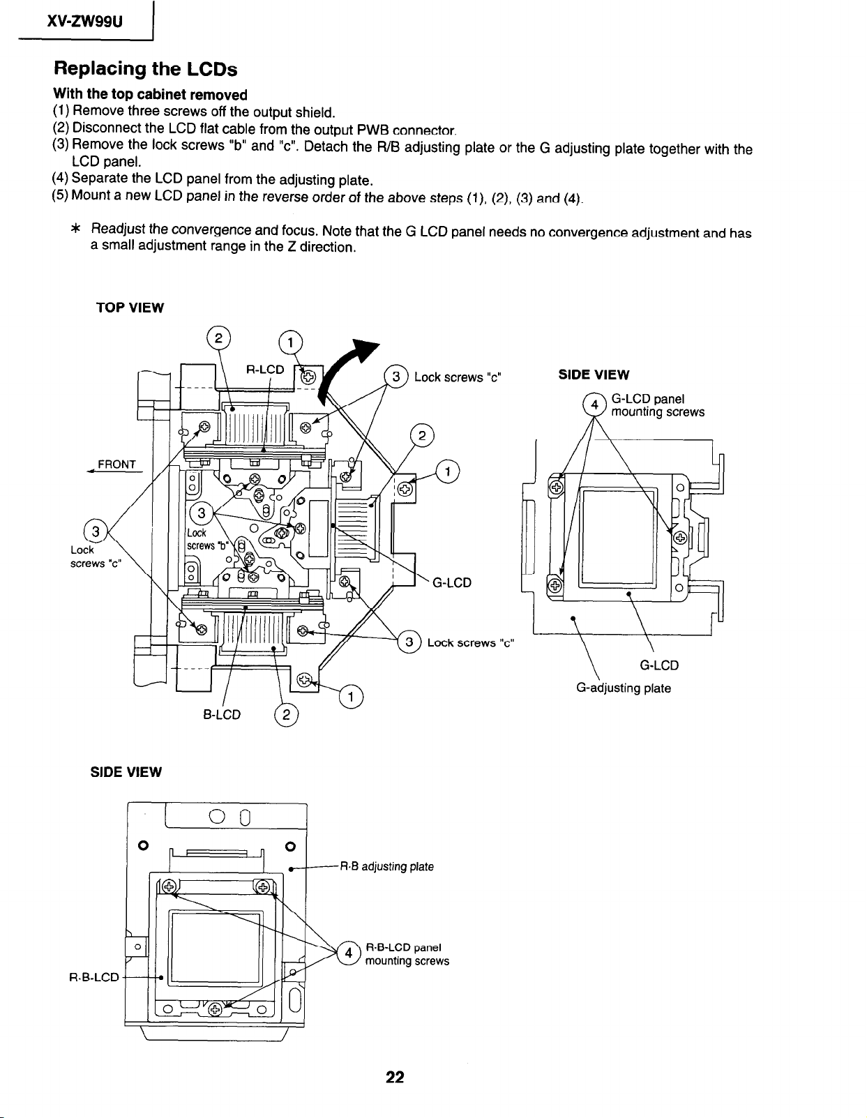
Replacing the LCDs
With the top cabinet removed
(1) Remove three screws off the output shield.
(2) Disconnect the LCD flat cable from the output PWB connector.
(3) Remove the lock screws “b” and “c”. Detach the R/B adjusting plate or the G adjusting plate together with the
LCD panel.
(4) Separate the LCD panel from the adjusting plate.
(5) Mount a new LCD panel in the reverse order of the above steps (l), (2) (3) and (4).
* Readjust the convergence and focus. Note that the G LCD panel needs no convergence adjustment and has
a small adjustment range in the Z direction,
TOP VIEW
FRONT
SIDE VIEW
Lock screws “c”
Lock screws “c”
SIDE VIEW
\
G-adjusting plate
G-LCD
FbB adjusting plate
FbB-LCD panel
mounting screws
FbB-LCD
I
xv-zw99u
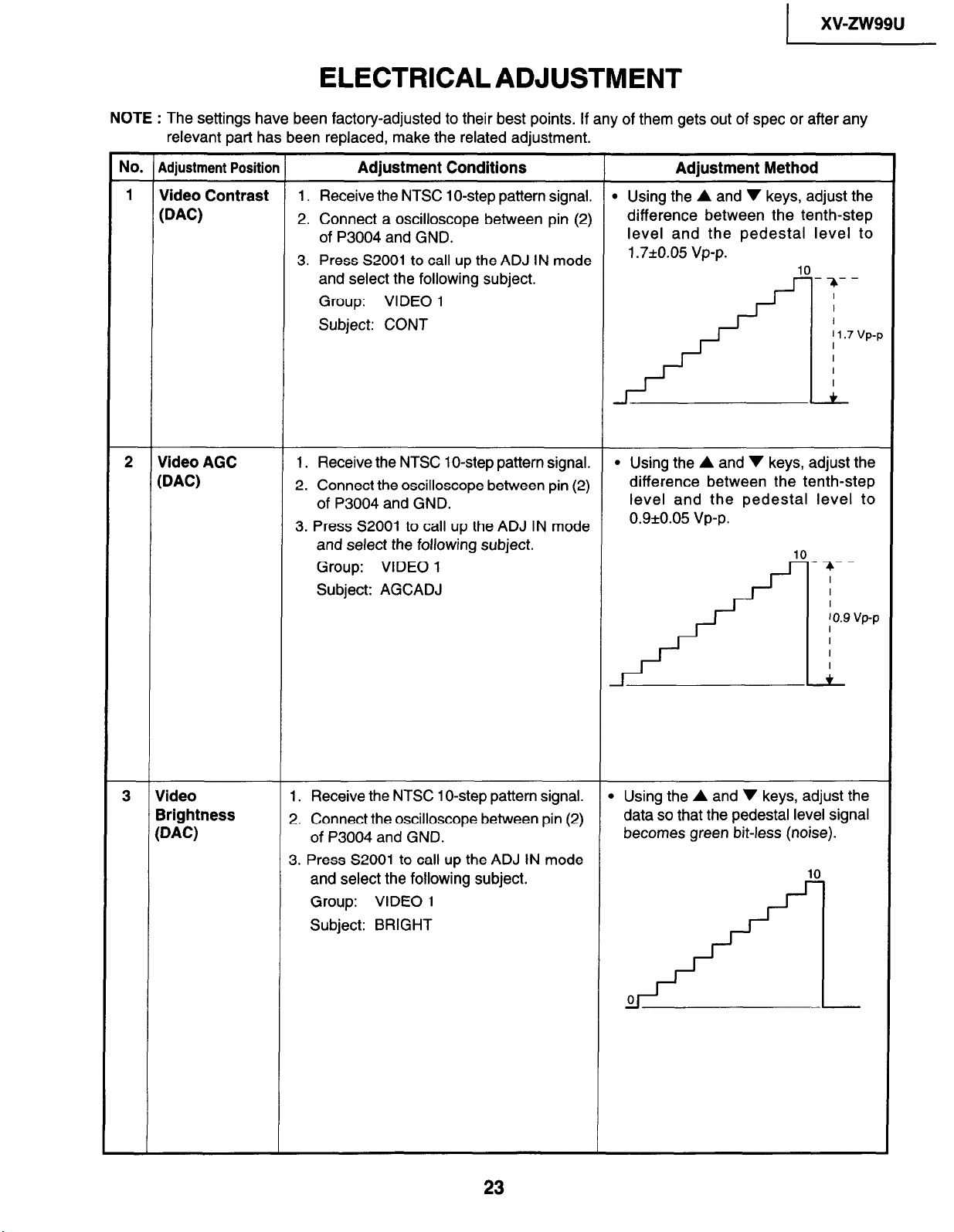
ELECTRICAL ADJUSTMENT
NOTE : The settings have been factory-adjusted to their best points. If any of them gets out of spec or after any
relevant part has been replaced, make the related adjustment.
NO. Adjustment Position
1
Video Contrast 1. Receive the NTSC 1 O-step pattern signal.
WC)
2. Connect a oscilloscope between pin (2)
Adjustment Conditions
of P3004 and GND.
3. Press S2001 to call up the ADJ IN mode
and select the following subject.
Group: VIDEO 1
Subject: CONT
2
Video AGC 1. Receive the NTSC 1 O-step pattern signal.
WC)
2. Connect the oscilloscope between pin (2)
of P3004 and GND.
3. Press S2001 to call up the ADJ IN mode
and select the following subject.
Group: VIDEO 1
Subject: AGCADJ
Adjustment Method
l Using the A and v keys, adjust the
difference between the tenth-step
level and the pedestal level to
1.7*0.05 vp-p.
10
-;c--
I
I
I
' 1.7 VP-F
I
I
I
I
+
l Using the A and v keys, adjust the
difference between the tenth-step
level and the pedestal level to
0.9*0.05 vp-p.
10
- ;c- -
I
I
3 Video
Brightness
WC)
1. Receive the NTSC 1 O-step pattern signal.
2. Connect the oscilloscope between pin (2)
of P3004 and GND.
3. Press S2001 to call up the ADJ IN mode
and select the following subject.
Group: VIDEO 1
Subject: BRIGHT
) 0.9 vp-p
I
I
I
I
+
l Using the A and v keys, adjust the
data so that the pedestal level signal
becomes green bit-less (noise).
10
23
xv-zw99u
1
No. ( Adjustment Position
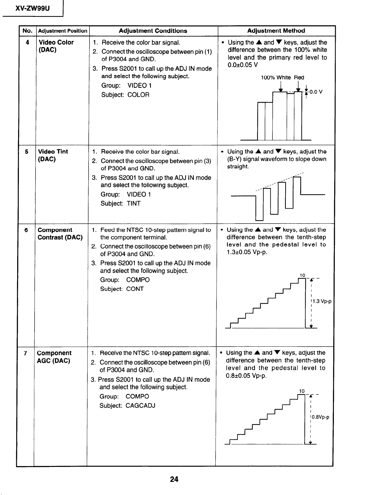
4 Video Color
@AC)
5 Video Tint 1. Receive the color bar signal.
@AC)
1. Receive the color bar signal. l Using the A and v keys, adjust the
2. Connect the oscilloscope between pin (1)
3. Press S2001 to call up the ADJ IN mode
2. Connect the oscilloscope between pin (3)
3. Press S2001 to call up the ADJ IN mode
Adjustment Conditions
of P3004 and GND.
and select the following subject.
Group: VIDEO 1
Subject: COLOR
of P3004 and GND.
and select the following subject.
Group: VIDEO 1
Subject: TINT
Adjustment Method
difference between the 100% white
level and the primary red level to
0.0*0.05 v
100% White Red
l Using the A and v keys, adjust the
(B-Y) signal waveform to slope down
straight.
0s
Component 1. Feed the NTSC lo-step pattern signal to
6
Contrast (DAC)
the component terminal.
2. Connect the oscilloscope between pin (6)
of P3004 and GND.
3. Press S2001 to call up the ADJ IN mode
and select the following subject.
Group: COMPO
Subject: CONT
7 Component
AGC (DAC)
1. Receive the NTSC 1 O-step pattern signal.
2. Connect the oscilloscope between pin (6)
of P3004 and GND.
3. Press S2001 to call up the ADJ IN mode
and select the following subject.
Group: COMPO
Subject: CAGCADJ
l Using the A and v keys, adjust the
difference between the tenth-step
level and the pedestal level to
1.3*0.05 vp-p.
10
-c-
I
I
I
Il.3 vp-p
I
I
I
I
+
l Using the A and v keys, adjust the
difference between the tenth-step
level and the pedestal level to
0.8kO.05 Vp-p.
10
-c I
I
24
I o.svp-p
I
I
I
I
+

1
xv-zw99u
Adjustment Position
No.
Component
8
Brightness
WAC)
Component
9
Color (DAC)
Adjustment Conditions Adjustment
1. Feed the
component
the
2. Connect
of P3004
and
S2001 to
select
3. Press
NTSC
the oscilloscope
lo-step pattern
terminal. data
and GND.
up the
call
the following
subject.
Group: COMPO
Subject: BRIGHT
Feed the
1.
NTSC color
bar signal to the
component terminal.
2. Connect the oscilloscope between pin (5)
of P3004 and GND.
Press S2001 to call up the ADJ IN mode
3.
and select the following subject.
Group: COMPO
Subject: COLOR
signal to
between
pin
ADJ IN mode
(6)
A and v keys, adjust the
the
Using
l
so that the pedestal level signal
becomes green
0
/-+-l-I
voltage
If the
l
following subject
the
select
again.
Group: COMPO
Subject: BRT2
Using the
l
A and v keys, adjust the
difference between
level and
the red level to
0.2kO.05 V
Method
bit-less (noise).
10
not properly adjusted,
is
and
100% white
the
White Red
100%
+r
L -To.*’
adjust
10 RGB
Brightness
@AC)
I1 R Offset
Offset
6
If the voltage is not
l
select the
following subject and adjust
properly adjusted,
again.
Group: COMPO
Subject: COL2
1. Feed the 16-step pattern signal(VGA or
computer input terminal.
SVGA) to
the
2. Connect the oscilloscope between pin (2)
9 Using the A and v keys, adjust
so that the pedestal level signal
data
becomes bit-less
(noise). 16
of P3004 and GND.
3. Press S2001 to call up the ADJ IN mode
and select the following subject.
Group: RGB
Subject: BRIGHT
Using the A and v keys, adjust the
1. Feed the 16-step pattern signal(VGA or
l
SVGA) to the computer input terminal. data so that the pedestal level
2. Connect the dual-beam oscilloscope
becomes bit-less (noise).
between pin (1) of P3004,pin(3) of P3004
and GND.
3. Press S2001 to call up the ADJ IN mode
and select the following subject.
Group:
RGB, RGB
Subject: R-OS, B-OS
the
16
xv-zw99u
1
NO. Adjustment Position
Adjustment Conditions
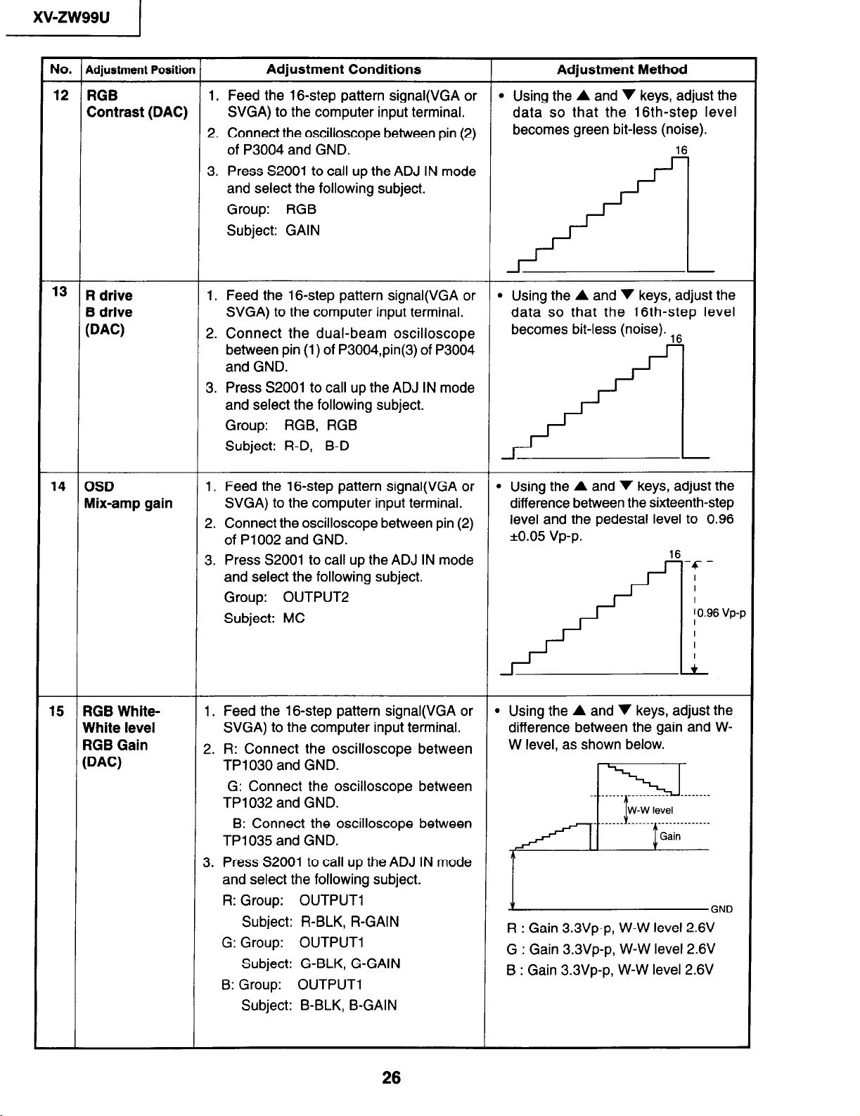
12 RGB 1. Feed the 16-step pattern signal(VGA or
Contrast (DAC) SVGA) to the computer input terminal.
2. Connect the oscilloscope between pin (2)
of P3004 and GND. 16
3. Press S2001 to call up the ADJ IN mode
and select the following subject.
Group: RGB
Subject: GAIN
l3 R drive
B drive
(DAC)
1. Feed the 16-step pattern signal(VGA or
SVGA) to the computer input terminal.
2. Connect the dual-beam oscilloscope
between pin (1) of P3004,pin(3) of P3004
and GND.
3. Press S2001 to call up the ADJ IN mode
and select the following subject.
Group: RGB, RGB
Subject: R-D, B-D
Adjustment Method
l Using the A and v keys, adjust the
data so that the 16th~step level
becomes green bit-less (noise).
l Using the A and ‘I keys, adjust the
data so that the 16th-step level
becomes bit-less (noise). ,6
14 OSD
Mix-amp gain
15 RGB White-
White level
RGB Gain
@AC)
1. Feed the 16-step pattern signal(VGA or l Using the A and 7 keys, adjust the
SVGA) to the computer input terminal.
2. Connect the oscilloscope between pin (2)
of P1002 and GND.
3. Press S2001 to call up the ADJ IN mode
and select the following subject.
difference between the sixteenth-step
level and the pedestal level to 0.96
*0.05 vp-p.
16
-c-
Group: OUTPUT2
Subject: MC
1. Feed the 16-step pattern signal(VGA or l Using the A and v keys, adjust the
SVGA) to the computer input terminal. difference between the gain and W-
2. R: Connect the oscilloscope between
W level, as shown below.
TP1030 and GND.
G: Connect the oscilloscope between
TP1032 and GND.
B: Connect the oscilloscope between
TP1035 and GND.
3. Press S2001 to call up the ADJ IN mode
A
.________ __.....____
W-W level
7
_.______ __....-
__________.___
Gain
________
and select the following subject.
R: Group: OUTPUT1
Subject: R-BLK, R-GAIN
G: Group: OUTPUT1
Subject: G-BLK, G-GAIN
V
R : Gain 3.3Vp-p, W-W level 2.6V
G : Gain 3.3Vp-p, W-W level 2.6V
B : Gain 3.3Vp-p, W-W level 2.6V
GNO
B: Group: OUTPUT1
Subject: B-BLK, B-GAIN
26
1
xwzw99u
No. Adjustment Position Adjustment Conditions
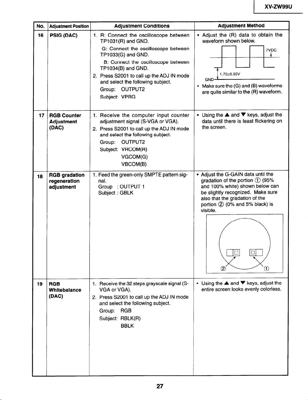
16 PSIG @AC) 1. R: Connect the oscilloscope between
TP1031(R) and GND.
G: Connect the oscilloscope between
TP1033(G) and GND.
6: Connect the oscilloscope between
TP1034(B) and GND.
2. Press S2001 to call up the ADJ IN mode
and select the following subject.
Group: OUTPUT2
Subject: VPRG
17 RGB Counter
Adjustment
@AC)
1. Receive the computer input counter
adjustment signal (S-VGA or VGA).
2. Press S2001 to call up the ADJ IN mode
and select the following subject.
Group:
OUTPUT2
Subject: VRCOM(R)
VGCOM(G)
VBCOM(B)
Adjustment Method
l Adjust the (R) data to obtain the
waveform shown below.
o*
l
Make sure the (G) and (B) waveforms
are quite similar to the (R) waveform.
l Using the A and v keys, adjust the
data until there is least flickering on
the screen.
13 RGB gradation 1. Feed the green-only SMPTE pattern sig-
regeneration
adjustment
nal.
Group : OUTPUT 1
Subject : GBLK
19 RGB
Whitebalance
@AC)
1. Receive the 32 steps grayscale signal (S-
VGA or VGA). entire screen looks evenly colorless.
2. Press S2001 to call up the ADJ IN mode
and select the following subject.
Group: RGB
Subject: RBLK(R)
BBLK
l Adjust the G-GAIN data until the
gradation of the portion @ (95%
and 100% white) shown below can
be slightly recognized. Make sure
also that the gradation of the
portion @ (0% and 5% black) is
visible.
. Using the A and ‘I keys, adjust the
27
)
xv-zw99u
No. Adiustment Position
.__. . .-,___“‘_.‘_ --._.-.. .-,-.--...-..- _ _.._._._.._
Adiustment Conditions
Adiustment Method
a
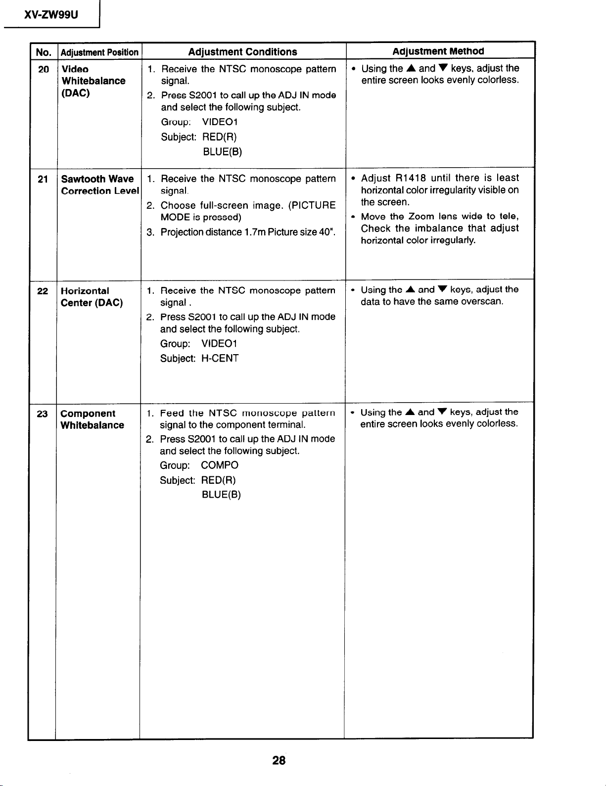
20 Video 1. Receive the NTSC monoscope pattern l Using the A and v keys, adjust the
Whitebalance signal.
WC)
2. Press S2001 to call up the ADJ IN mode
entire screen looks evenly colorless.
and select the following subject.
Group: VIDEO1
Subject: RED(R)
BLUE(B)
21 Sawtooth Wave 1. Receive the NTSC monoscope pattern l Adjust R1418 until there is least
Correction Level signal.
2. Choose full-screen image. (PICTURE
MODE is pressed)
3.
Projection distance 1.7m Picture size 40”.
horizontal color irregularity visible on
the screen.
l Move the Zoom lens wide to tele,
Check the imbalance that adjust
horizontal color irregularly.
22 Horizontal
Center (DAC)
1. Receive the NTSC monoscope pattern
signal .
l Using the A and v keys, adjust the
data to have the same overscan.
2. Press S2001 to call up the ADJ IN mode
and select the following subject.
Group: VIDEO1
Subject: H-CENT
23 Component
Whitebalance
1. Feed the NTSC monoscope pattern
signal to the component terminal.
2. Press 52001 to call up the ADJ IN mode
and select the following subject.
Group: COMPO
Subject: RED(R)
BLUE(B)
l Using the A and v keys, adjust the
entire screen looks evenly colorless.
28
(
xv-zw99u
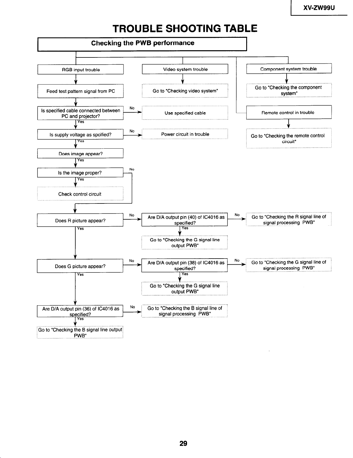
TROUBLE SHOOTING TABLE
Checking the PWB performance
1
I
RGB input trouble
1
I
I
J
Feed test pattern signal from PC
PC and projector?
Is supply voltage as spcified?
Does image appear?
Yes
\1
Check control circuit i
Does R picture appear?
I Yes
’ ”
NO
Use specified cable
Power circuit in trouble
0..
( Go to “Checking the G signal line
output PWB”
j : Go to “Checking video system”
: Go to “Checking the component !
system”
-’
:’ “‘.’
: Go to “Checking the remote control
circuit”
No +’ Go to “Checking the R signal line of
signal processing PWB”
i
v
Does G picture appear?
Yes
Yes
‘Go to “Checking the B signal line output:
1 No
Are D/A 07 No ) Go to “Checking the G Signal line of i
specified?
! .“‘.“’
: Go to “Checking the G signal line
output PWB”
Go to “Checking the B signal line of
signal processing PWB”
signal processing PWB”
:
:
29
 Loading...