

Page 1
Connections
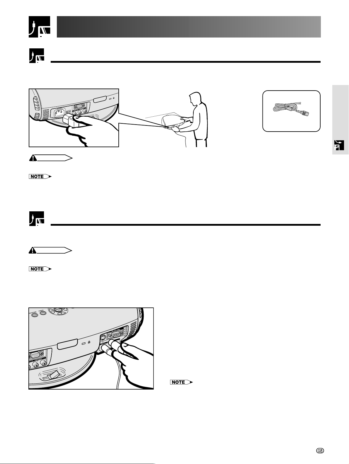
Power Supply
Connecting the Power Cord
Plug the supplied power cord into the AC socket on the back of the projector.
Power cord
CAUTION
• Make sure the power cord is firmly connected into the AC socket.
• The projector will enter the standby mode as you re-plug it into the AC socket, when unplugging the power cord after turning the power
off by pressing the POWER button. However, if the projector was turned off by disconnecting the power cord or by a power failure, the
projector will automatically turn on when plugging the power cord again.
Setup & Connections
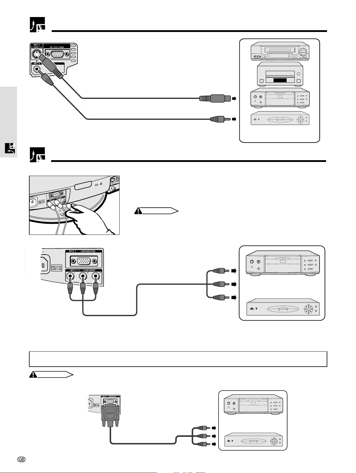
Connecting to Video Equipment
You can connect your projector to a VCR, laser disc player, DVD player, DTV* decoder and other video equipment.
* DTV is the umbrella term used to describe the new digital television system in the United States.
CAUTION
• Make sure to turn both the projector and the video equipment off, before connecting.
• As this projector is not equipped with audio input terminals, commercially available audio equipment or your own equipment (such as
speakers or amplifiers) should be used.
Connecting a video source (VCR, laser disc player, DVD player or DTV decoder) using the INPUT 3
S-VIDEO and INPUT 4 VIDEO terminals
1 Connect one end of the S-video cable (commercially
available) to the INPUT 3 S-VIDEO terminal, or one end
of the video cable to the INPUT 4 VIDEO terminal on
the projector.
2 Connect the other end of the S-video cable or the video
cable to the S-video output or Video output terminal of
the video source.
The S-video input terminal uses a video signal system where
the picture is separated into a colour and luminance signal
to realise a higher-quality image.
• For higher quality video, you may use the S-video input terminal on the
projector. An S-video cable is commercially available.
• If your video equipment does not have an S-video output terminal, use
the composite video output terminal.
-12
Page 2
Projector
Connecting to Video Equipment
1
1
Setup & Connections
S-video cable (commercially available)
2 To S-video output terminal
Video cable
2 To video output terminal
VCR, Laser disc player,
DVD player or DTV decoder
Connecting to a DVD Player and DTV Decoder
Connecting to a DVD player and DTV decoder with Component output (for INPUT 1)
1 Connect each RCA connector of a component cable to the corresponding
RCA INPUT 1 terminals on the projector.
2 Connect the other end of the cable to the corresponding terminals on a DVD
player or DTV decoder.
CAUTION
• Make sure to turn both the projector and the video equipment off, before
connecting.
Projector
2 To component output
terminals
DVD player
Component cable
(commercially available)
1
or
DTV decoder
Connecting to a DVD player and DTV decoder with component output (for INPUT 2)
1 Connect the 3 RCA to 15-pin D-Sub cable to INPUT 2 COMPONENT/RGB port on the projector.
2 Use the above cables to connect the DTV decoder or DVD player.
When connecting this projector to analog RGB output of the DTV decoder, select “Component” for “Signal Type” on the
OSD menu or press RGB/COMP. on the remote control. (See page 36.)
CAUTION
• Make sure to turn both the projector and the video equipment off, before connecting.
Projector
1
3 RCA to 15-pin D-sub cable
(sold separately AN-C3CP)
2
DVD player
or
DTV decoder
-13
Page 3
Connecting to a DVD Player and DTV Decoder
Connecting to a DTV decoder with analog RGB output
1 Connect the computer-RGB cable to the INPUT 2 COMPONENT/RGB port.
2 Connect the other end to the corresponding terminal on a DTV decoder.
When connecting this projector to analog RGB output of the DTV decoder, select “Component” for “Signal Type” on the
OSD menu or press RGB/COMP. on the remote control. (See page 36.)
CAUTION
• Make sure to turn both the projector and the video equipment off, before connecting.
Projector
1
Computer-RGB cable
2
DTV decoder
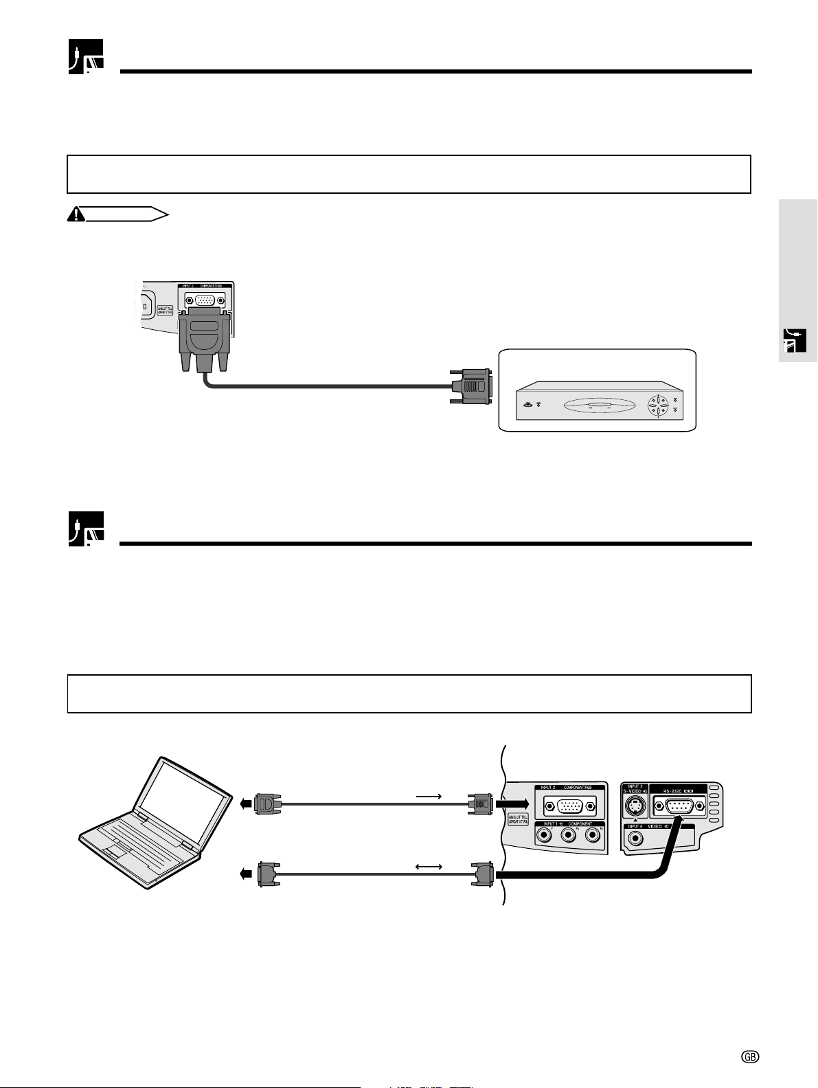
Connecting to a Computer
When the RS-232C port on the projector is connected to a computer with an RS-232C cable (null modem, cross
type, commercially available), the computer can be used to control the projector and check the status of the
projector. See pages 52 and 53 for details.
Setup & Connections
Connecting a computer with analog RGB output
1 Connect the computer-RGB cable end to the INPUT 2 COMPONENT/RGB port on the projector.
2 Connect the other end to the computer.
When connecting this projector to a DVD player or DTV decoder, select “RGB” for “Signal Type” on the OSD menu or press
RGB/COMP. on the remote control. (See page 36.)
Computer-RGB cable
RS-232C cable
(null modem, cross type, commercially available)
12
-14
Page 4
Connecting to a Computer
Connecting a computer with RGB output
1 Connect one of the computer-RGB cable to the INPUT 2 COMPONENT/RGB port on the projector.
2 Connect the other end to the Corresponding terminal on a computer.
• Make sure to turn both the projector and the video equipment off, before connecting.
Computer-RGB cable
Connect an RS-232C cable (null modem, cross type, commercially available) to the serial port on the computer.
Setup & Connections
12
CAUTION
• Do not connect or disconnect an RS-232C cable to or from the computer while it is on. This may damage your computer.
• Refer to “Computer Compatibility Chart” on page 54 for a list of computer signals compatible with the projector. Use with computer
signals other than those listed may cause some of the functions not to work.
• The RS-232C function may not operate if your computer port is not correctly set up. Please refer to the operation manual of the computer for
details.
• The arrows (→, ↔) in the configuration above indicate the direction of the signals.
• A Macintosh adaptor may be required for use with some Macintosh computers. Contact your nearest Sharp Authorised Projector Dealer or
Service Centre.
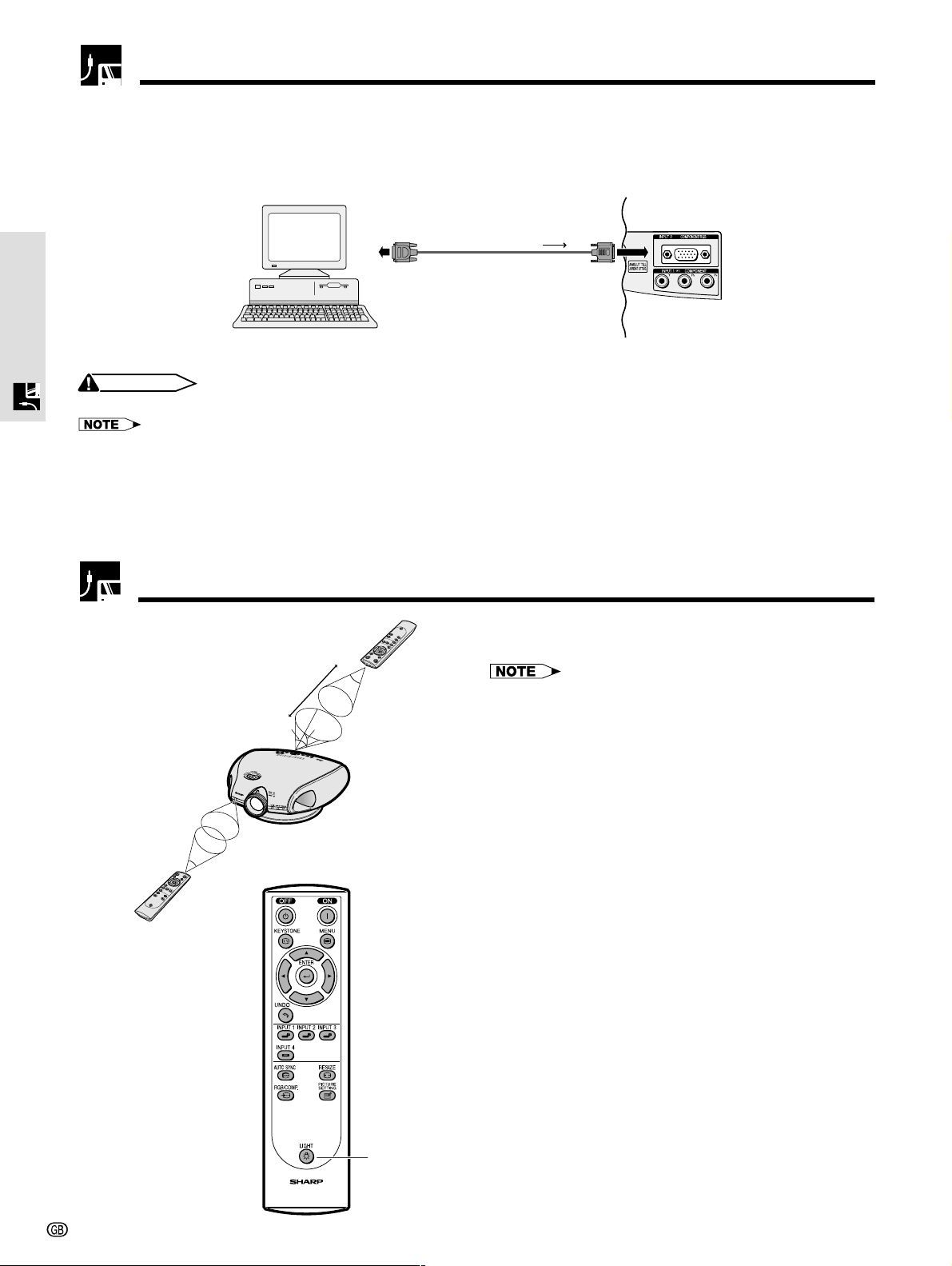
Operating the Remote Control
Remote Control
7 m
45˚
30˚
30˚
The remote control can be used to control the projector within the range shown on the left.
• The signal from the remote control can be reflected off a
screen for easy operation. However, the effective distance
of the signal may differ due to the screen material.
Remote Control
-15
45˚
30˚
Using the remote control in a dark
room
The backlights of the operation buttons can be turned
on for five seconds and off by pressing LIGHT. If you
want to turn off the backlights while they are on, press
LIGHT again.
LIGHT button
Page 5

Power ON/OFF
POWER (ON/OFF)
buttons
TEMP. LAMP POWER
Press POWER ON.
• The blinking green LAMP REPLACEMENT indicator
shows that the lamp is warming up. Wait until the
indicator stops blinking before operating the projector.
• If the power is turned off and then immediately turned
on again, it may take a short while before the lamp
turns on.
• After the projector is unpacked and turned on for the first
time, a slight odor may be emitted from the exhaust
ventilative hole. This odor will soon disappear with use.
When the power is on, the LAMP REPLACEMENT
indicator illuminates, indicating the status of the
lamp.
Green: Lamp is ready.
Green blinking: Warming up. / Cooling down.
Red: Change the lamp.
Press POWER OFF.
• Press POWER OFF again while the confirmation
message is displayed. Then, message “Terminating.
Please wait.” will appear.
Setup & Connections
• If you accidentally pressed POWER OFF and do not want
to turn off the power, wait until the confirmation message
disappears.
• When POWER OFF is pressed twice, the POWER indicator
will illuminate in red and the cooling fan will run for about
90 seconds. The projector will then enter standby mode.
• Wait until the cooling fan stops running before disconnecting
the power cord.
• The power can be turned on again by pressing POWER
ON. When the power is turned on, the POWER indicator
and the LAMP REPLACEMENT indicators illuminate in
green.
A dimly lit screen is displayed for a short time
(about 20 seconds) to reduce lamp damage.
Zooming and Focusing
The picture can be zoomed in or out, and focused by the Zoom knob and the Focus ring.
1 Slide the Zoom knob. The image can be adjusted
to the desired size within the zoom range.
2 Rotate the Focus ring until the image on the screen
becomes clear.
1
2
-16
Page 6

Setting Up the Screen
Using the Swivel Stand
1
2
Setup & Connections
3
You can adjust the angle and direction of the projected image by using
the Swivel Stand.
1 Unlock the lever on the Swivel Stand.
2 Adjust the angle and direction of the projected image as you want
by lifting up the projector and rotating the projector on the Swivel
Stand.
3 Lock the lever on the Swivel Stand.
Adjustable up to
±10° from the
standard position.
Adjustable up to
±25° from the
standard position.
Adjustable up to
±3° from the
standard position.
-17
2
Removing the Swivel Stand
Lift the projector (2) with pressing the removing-stand button on the
back of the projector (1).
Attaching the Swivel Stand
Align the tabs on the front bottom of the projector (1). While holding
down the button (2), place the projector onto the Swivel Stand (3) to
1
Removingstand button
1
3
2
attach.
Press the projector down firmly to attach
it to the Swivel Stand to make sure it is
securely attached to the Swivel Stand.
CAUTION
• Do not hold the lens when lifting, lowering or rotating the projector.
• When lowering the projector, be careful not to get your fingers caught in the
area between the Swivel Stand and the projector.
• When the height or direction of the projector is adjusted, the image may become
distorted (keystoned), depending on the relative positions of the projector
and the screen. See page 19 for details on the keystone correction.
Page 7

Using the Lens Shift
The picture can be adjusted within the shift range of the lens by rotating the lens shift dial on the top of the
projector using your finger.
Projector
DOWN UP
Lens shift dial
Projected Image
UP
DOWN
Setup & Connections
-18
Page 8

Keystone Correction
1, 4
This function can be used to adjust the Keystone
settings.
• For details about using the menu screen, see page 26.
Description of 2D Keystone Correction
Selected item Description
H Keystone Horizontally adjusts the keystone settings.
V Keystone Vertically adjusts the keystone settings.
Reset V and H Keystone adjustments are returned to the factory
preset settings.
Setup & Connections
2, 3
Horizontal Keystone Correction
Vertical Keystone Correction
1 Press KEYSTONE on the projector or on the
remote control.
2 Press / to select “H Keystone” or “V
Keystone”.
3 Press / to move the mark on the selected
adjustment item to the desired setting.
-19
4 To return to the normal screen, press KEYSTONE
again.
• Straight lines and the edges of the displayed image may
appear jagged, when adjusting the Keystone setting.
• When adjusting “H Keystone” and “V Keystone” at the same
time, the values of adjustable angles for each setting
become smaller.
• The “Digital Shift” and “Subtitle” cannot be adjusted when
Keystone correction is applied.
Page 9

Placement of the Projected Image Using the Keystone Correction
Place the projector at a distance from the screen that allows images to
be projected onto the screen by referring to “Adjusting the Projection
Distance” on pages 21 and 22.
: Screen area
Setup & Connections
1 Project the test pattern of the Keystone correction function onto the
screen. Rotate the Focus ring until the image on the screen becomes
clear. (See page 16.)
2 Change the projection angle using the Swivel Stand to properly
project images onto the screen. (See page 17).
3 Align the edge of the screen closest to the projector with the test
pattern by adjusting the zoom and the Swivel Stand. (See pages 16
and 17.)
4 Adjust the Keystone function so that the size of the projected image
matches the screen size. (See page 19.)
5 Align the image on the screen by adjusting the zoom function and the
Swivel Stand.
6 Adjust the focus so that the projected image is in focus at the centre
of the screen. (See page 16.)
• The aspect ratio of the projected image shifts slightly when the lens
shift is at a position other than the top position.
• The aspect ratio of the projected image also shifts slightly when the “H
Keystone” and “V Keystone” functions are adjusted simultaneously.
-20
Page 10

Adjusting the Projection Distance
• Refer to pages 19 and 20 about the function of Keystone correction and placement of projector using the correction.
• Decide the placement of the projector referring to the figures on the table and the diagram below according to the size of
your screen and the input signal.
(b)
Setup & Connections
(a)
When using a
normal screen (4:3)
4
: Screen area
Centre of the screen
(d)
(c)
±10°
(e)
508cm (200")
381cm (150")
3
254cm (100")
213cm (84")
183cm (72")
152cm (60")
102cm (40")
(f)
Screen size
(4:3)(x)
Diag.
Placement range
Projection
distance (a)
–
5.6 m (18' 5")
3.7 m (12' 3")
3.1 m (10' 2")
2.7 m (8' 9")
2.2 m (7' 3")
1.5 m (4' 11")
Maximum projection distance
Horizontal Placement range (c)
Composite, S-video
480I/P, 1080I
–
1.7 m (5' 7")
1.1 m (3' 7")
0.9 m (2' 11")
0.8 m (2' 7")
0.6 m (1' 12")
0.4 m (1' 4")
1.2 m (3' 11")
0.8 m (2' 7")
0.6 m (1' 12")
0.5 m (1' 8")
0.4 m (1' 4")
0.3 m (12")
(a) Maximum projection distance
(b) Minimum projection distance
(c) Horizontal placement range when projection distance is maximum.
(d) Horizontal placement range when projection distance is minimum.
(e) Vertical placement range when projection distance is maximum.
(f) Vertical placement range when projection distance is minimum.
• The aspect ratio of the projected image shifts slightly when the
lens shift is at a position other than the top position.
• The aspect ratio of the projected image also shifts slightly
when the “H Keystone” and “V Keystone” functions are
adjusted simultaneously.
• Keystone correction cannot be applied to On Screen Display.
• When Keystone correction is applied, the resolution of image
can be deteriorated to some extent.
• There are errors of ±3% in the formulas below.
Projection distance and Keystone correction
Minimum projection distance
Horizontal Placement range (d)
Composite, S-video
480I/P, 1080I
1.5 m (4'11")
1.1 m (3' 7")
0.7 m (2' 4")
0.6 m (1'12")
0.5 m (1' 8")
0.4 m (1' 4")
0.3 m (12")
1.1 m (3' 7")
0.8m (2' 7")
0.5m (1' 8")
0.4 m (1' 4")
0.3m (12")
0.3 m (12")
0.2 m ( 8")
720P
RGB
0.8 m (2' 7")
0.6 m (1'12")
0.4 m (1' 4")
0.3 m (12")
0.3 m (12")
0.2 m ( 8")
0.1 m ( 4")
720P
Vertical
placement range
RGB
–
–
0.9 m (2' 11")
0.6 m (1' 12")
0.5 m (1' 8")
0.4 m (1' 4")
0.3 m (12")
0.2 m ( 8")
1.2 m (3'11")
0.8 m (2' 7")
0.7 m (2' 4")
0.6 m (1'12")
0.5 m (1' 8")
0.3 m (12")
Projection
distance (b)
(e)
–
6.2 m (20' 4")
4.6 m (15' 3")
3.1 m (10' 2")
2.6 m (8' 6")
2.2 m (7' 3")
1.8 m (6")
1.2 m (3' 11")
Vertical
placement range
(f)
1.4 m (4' 7")
1.0 m (3' 3")
0.7 m (2' 4")
0.5 m (1' 8")
0.5 m (1' 8")
0.4 m (1' 4")
0.2 m ( 8")
When using a wide
screen (16:9)
16
: Picture area
: Area covered by the
projection panel of
the projector
9
Screen size
(16:9)(x)
Diag.
508cm (200")
381cm (150")
338cm (133")
269cm (106")
254cm (100")
234cm (92")
213cm (84")
183cm (72")
152cm (60")
102cm (40")
Projection
distance (a)
8.2 m (26'11")
6.1 m (20' 1")
5.4 m (17'10")
4.3 m (14' 2")
4.1 m (13' 4")
3.7 m (12' 3")
3.4 m (11' 2")
2.9 m (9' 7")
2.4 m (7' 11")
1.6 m (5' 3")
Projection distance and Keystone correction
Maximum projection distance Minimum projection distance
Horizontal Placement range (c) Horizontal Placement range (d)
Composite, S-video
480I/P, 1080I
2.5 m (8' 2")
1.8 m (5'11")
1.6 m (5' 3")
1.3 m (4' 3")
1.2 m (3'11")
1.1 m (3' 7")
1.0 m (3' 3")
0.8 m (2' 7")
0.7 m (2' 4")
0.4 m (1' 4")
720P
1.8 m (5' 11")
1.3 m (4' 3")
1.1 m (3' 7")
0.9 m (2' 11")
0.9 m (2' 11")
0.8 m (2' 7")
0.7 m (2' 4")
0.6 m (1' 12")
0.5 m (1' 8")
0.3 m (12")
RGB
1.4 m (4' 7")
1.0 m (3' 3")
0.9 m (2'11")
0.7 m (2' 4")
0.7 m (2' 4")
0.6 m (1'12")
0.5 m (1' 8")
0.4 m (1' 4")
0.4 m (1' 4")
0.2 m ( 8")
Vertical
placement range
(e)
1.8 m (5'11")
1.4 m (4' 7")
1.2 m (3'11")
0.9 m (2'11")
0.9 m (2'11")
0.8 m (2' 7")
0.7 m (2' 4")
0.6 m (1'12")
0.5 m (1' 8")
0.3 m (12")
Projection
distance (b)
6.8 m (22' 2")
5.1 m (16' 7")
4.5 m (14' 9")
3.6 m (11' 8")
3.4 m (11')
3.1 m (10' 2")
2.8 m (9' 3")
2.4 m (7'11")
2.0 m (6' 7")
1.3 m (4' 3")
Composite, S-video
480I/P, 1080I
1.6 m (5' 3")
1.2 m (3'11")
1.1 m (3' 7")
0.8 m (2' 7")
0.8 m (2' 7")
0.7 m (2' 4")
0.6 m (1'12")
0.5 m (1' 8")
0.4 m (1' 4")
0.3 m (12")
1.2 m (3' 11")
0.9 m (2' 11")
0.8 m (2' 7")
0.6 m (1' 12")
0.6 m (1' 12")
0.5 m (1' 8")
0.5 m (1' 8")
0.4 m (1' 4")
0.3 m (12")
0.2 m ( 8")
720P
RGB
0.9 m (2'11")
0.7 m (2' 4")
0.6 m (1'12")
0.5 m (1' 8")
0.4 m (1' 4")
0.4 m (1' 4")
0.4 m (1' 4")
0.3 m (12")
0.2 m ( 8")
0.1 m ( 4")
Vertical
placement range
(f)
1.5 m (4'11")
1.1 m (3' 7")
1.0 m (3' 3")
0.8 m (2' 7")
0.7 m (2' 4")
0.7 m (2' 4")
0.6 m (1'12")
0.5 m (1' 8")
0.4 m (1' 4")
0.2 m ( 8")
-21
Page 11

Adjusting the Projection Distance
Upper and Lower Lens Shift Position
• This projector is equipped with a lens shift function that lets you adjust the projection height.
• Adjust it to match the setup configuration.
• The screen can be moved maximum the length of one screen vertically using the lens shift.
• Optimal image quality is produced with the projector positioned perpendicular to the screen with all feet flat and level. Tilting or angling
the projector will reduce the effectiveness of the lens shift function.
Screen size: 254 cm (100 inches)
Aspect ratio: 4:3
Setup & Connections
Screen
90°
90°
Lower edge of screen (White portion) =
Standard (0) point
Lens centre
Upper lens shift position
(High mount setup)
Lens centre
Lower lens shift position
(Desktop setup)
Upper and Lower Lens Shift Position (Ceiling Mount)
When the projector is in the inverted position, use the upper edge of the screen as the base line, and exchange
the lower and upper lens shift values.
Screen size: 254 cm (100 inches)
Aspect ratio: 4:3
Screen
90°
90°
-22
Page 12

Rear Projection
Setup & Connections
Projection Using a Mirror
Image Projection
• Place a translucent screen between the projector and
the audience.
• Use the projector’s menu screen to reverse the
projected image. (See page 42 for use of this
function.)
• Optimal image quality can be achieved when the projector
is positioned perpendicular to the screen with all feet flat
and leveled.
• When the distance between the projector and a
screen is not sufficient for normal rear projection, you
can use a mirror to reflect the image onto the screen.
• Place a mirror (normal flat type) in front of the lens.
• Project the normal image onto the mirror.
• The image reflected from the mirror is projected onto
the translucent screen.
• When using a mirror, be sure to carefully position both the
projector and the mirror so the light does not shine into the
eyes of the audience.
Ceiling-mount Projection
• It is recommended that you use the optional Sharp
ceiling-mount bracket for this installation.
• Before mounting the projector, remove the Swivel
Stand. (See page 17 for removing and attaching the
Swivel Stand.)
• Before mounting the projector, contact your nearest
Sharp Authorised Projector Dealer or Service Centre
to obtain the recommended ceiling-mount bracket
(sold separately). (AN-TK202 ceiling-mount bracket,
AN-TK201 extension tube, AN-60KT ceiling adaptors
for AN-TK202 or AN-TK201)
• When the projector is in the inverted position, use the
upper edge of the screen as the base line.
• Use the projector’s menu screen to select the
appropriate projection mode. (See page 42 for use
of this function.)
CAUTION
-23
 Loading...