

Page 1
SERVICE MANUAL
THEATOR PROJECTOR
XV-Z90U
XV-Z90U
DT-200
S02S1XV-Z90U/
MODELS
In the interests of user-safety (Required by safety regulations in some countries) the set should be restored
to its original condition and only parts identical to those specified should be used.
CONTENTS
» SPECIFICATIONS ......................................................................................................................................2
» IMPORTANT SERVICE SAFETY
NOTES (for USA) .......................................................................................................................................3
» NOTE TO SERVICE PERSONNEL............................................................................................................4
» OPERATION MANUAL ...............................................................................................................................8
» REMOVING OF MAJOR PARTS ..............................................................................................................13
» RESETTING THE TOT AL LAMP TIMER..................................................................................................18
» ELECTRICAL ADJUSTMENT ....................................................................................................................19
» TROUBLE SHOOTING TABLE ................................................................................................................24
» CHASSIS LAYOUT ...................................................................................................................................34
» BLOCK DIAGRAM....................................................................................................................................36
» OVERALL WIRING DIAGRAM .................................................................................................................38
» SCHEMATIC DIAGRAM ...........................................................................................................................40
» PRINTED WIRING BOARD ASSEMBLIES..............................................................................................75
» PARTS LIST
Ë
ELECTRICAL PARTS ............................................................................................................................81
Ë
CABINET AND MECHANICAL PARTS..................................................................................................94
Ë
ACCESSORIES PA RTS ........................................................................................................................98
Ë
PACKING PARTS ..................................................................................................................................98
» PACKING OF THE SET............................................................................................................................99
DT-200
Page
SHARP CORPORATION
This document has been published to be used for
after sales service only.
The contents are subject to change without notice.
Page 2

XV-Z90U
DT-200
Specifications
Product type Theater Projector
Model XV-Z90U/DT-200
Video system PAL/PAL 60/PAL-M/PAL-N/SECAM/NTSC 3.58/NTSC 4.43/DTV 480i/480P/720P/1080i
Display method DLP chip, RGB optical shutter method
DLP panel Panel size: 0.55” (140mm)
Display method: Single Panel Digital Micromirror Device (DMD™) by Texas Instruments
Drive method: Digital Light Processing (DLP)
No. of dots: 480,000 dots (800 [H] x 600 [V])
Lens 1–1.2 x zoom lens, F1.75–2.04, f=28–33.5 mm (XV-Z90U) F2–2.4, f=16.9–20.2 mm (DT-200)
Projection lamp DC150 W SHP lamp
Video input signal RCA Connector: VIDEO (INPUT 4), composite video, 1.0 Vp-p, sync negative, 75 Ω terminated
S-video input signal 4-pin Mini DIN connector (INPUT 3)
Y (luminance signal): 1.0 Vp-p, sync negative, 75 Ω terminated
C (chrominance signal): Burst 0.286 Vp-p, 75 Ω terminated
Component input signal RCA Connector
(INPUT 1) Y: 1.0 Vp-p, sync negative, 75 Ω terminated
PB: 0.7 Vp-p, 75 Ω terminated
PR: 0.7 Vp-p, 75 Ω terminated
Component input signal 29-pin connector
(INPUT 2) DVI input signal: Digital 250–1,000 mV 50 Ω
Y: 1.0 Vp-p, sync negative, 75 Ω terminated
PB: 0.7 Vp-p, 75 Ω terminated
PR: 0.7 Vp-p, 75 Ω terminated
Component RGB input signal 29-pin connector
(INPUT 2) RGB separate/sync on green type analog input: 0–0.7 Vp-p, positive, 75 Ω terminated
HORIZONTAL SYNC. SIGNAL: TTL level (positive/negative)
VERTICAL SYNC. SIGNAL: Same as above
Horizontal resolution 520 TV lines (NTSC 3.58 input)
RGB input signal 29-PIN CONNECTOR (INPUT 2):
RGB separate/composite sync/sync on green type analog input: 0–0.7 Vp-p, positive,75 Ω terminated
HORIZONTAL SYNC. SIGNAL: TTL level (positive/negative) or composite sync (Apple only)
VERTICAL SYNC. SIGNAL: Same as above
Pixel clock 12–110 MHz
Vertical frequency 43–75 Hz
Horizontal frequency 15–70 kHz
Computer control signal 9-pin D-sub connector (RS-232C Port)
Rated voltage AC 100–240 V
Input current 2.1 A
Rated frequency 50/60 Hz
Power consumption 200 W
Heat dissipation 750 BTU/hour
Operating temperature 41°F to 95°F (+5°C to +35°C)
Storage temperature – 4°F to 140°F (– 20°C to +60°C)
Cabinet Plastic
I/R carrier frequency 38 kHz
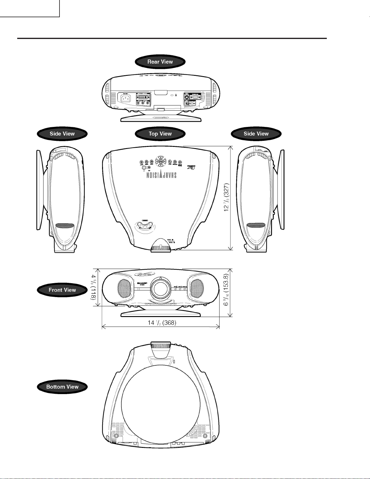
Dimensions (approx.) 14 1⁄2” (W) x 6 9⁄16” (H) x 12 7⁄8” (D) (368 x 153.8 x 327 mm) (including swivel stand)
14 1⁄2” (W) x 4 5⁄8” (H) x 12 7⁄8” (D) (368 x 118 x 327 mm) (main body only)
Weight (approx.) 9.5 lbs. (4.3 kg) (including swivel stand)
8.4 lbs. (3.8kg) (main body only)
Supplied accessories Remote control, Two AA size batteries, Power cord (1.8 m), Terminal cover (XV-Z90U), Lens cap (attached
on the body), Lens cap strap, Operation manual, Screws for terminal cover (XV-Z90U)
Replacement parts Lamp unit (Lamp/cage module) (BQC-XVZ90+++1), Remote control (RRMCGA064WJSA:XV-Z90U,
RRMCGA088WJSA:DT-200), AA size batteries, Power cord (QACCDA007WJPZ), Terminal cover
(GCOVAA116WJKA:XV-Z90U), Lens cap (CCAPHA004WJ01), Lens cap strap (UBNDT0013CEZZ), Operation manual (TiNS-A286WJZZ:XV-Z90U,TiNS-A287WJZZ:DT-200), Screws for terminal cover
(XBBSN40P10000:XV-Z90U)
Analog 0.7 Vp-p 75 Ω
This SHARP projector uses a DMD chip. This very sophisticated chip
contains 480,000 pixels. As with any high technology electronicequipment
such as large screen TVs, video systems and videocameras, there are
certain acceptable tolerances that the equipment must conform to.
Specifications are subject to change without notice.
This unit has some inactive pixels within acceptable tolerances which
may result in inactive dots on the picture screen. This will not affect the
picture quality or the life expectancy of the unit. If you have any questions about this matter, please call toll free 1-877-DTV-SHARP (1-877388-7427). U.S.A. ONLY
2
Page 3

XV-Z90U
2
2
DT-200
IMPORTANT SERVICE SAFETY NOTES (for USA)
Ë Service work should be performed only by qualified service technicians who are
thoroughly familiar with all safety checks and servicing guidelines as follows:
WARNING
1. For continued safety, no modification of any circuit
should be attempted.
2. Disconnect AC power before servicing.
BEFORE RETURNING THE PROJECTOR:
(Fire & Shock Hazard)
Before returning the projector to the user, perform
the following safety checks:
1. Inspect lead wires are not pinched between the
chassis and other metal parts of the projector.
2. Inspect all protective devices such as non-metallic
control knobs, insulating materials, cabinet backs,
adjustment and compartment covers or shields,
isolation resistor-capacity networks, mechanical
insulators, etc.
3. To be sure that no shock hazard exists, check for
current leakage in the following manner:
» Plug the AC cord directly into a 120-volt AC outlet,
(Do not use an isolation transformer for this test).
» Using two clip leads, connect a 1.5k ohm, 10 watt
resistor paralleled by a 0.15µF capacitor in parallel
between all exposed metal cabinet parts and earth
ground.
» Use an AC voltmeter with sensitivity of 5000 ohm
per volt., or higher, sensitivity to measure the AC
voltage drop across the resistor (See Diagram).
» All checks must be repeated with the AC plug
connection reversed. (If necessary, a non-polarized
adapter plug must be used only for the purpose of
completing these checks.)
Any reading of 0.3 volts RMS (this corresponds to
0.2 milliamp. AC.) or more is excessive and indicates
a potential shock hazard which must be corrected
before returning the unit to the owner.
AC
VOLTMETER
1.5k ohm (10W)
0.15µF
TEST PROBE
TO EXPOSED
METAL PARTS
CONNECT TO KNOWN
EARTH GROUND
234567890123456789012345678901212345678901234567890123456789012123456789012345678901234567890121
SAFETY NOTICE
Many electrical and mechanical parts in Projector have
special safety-related characteristics.
These characteristics are often not evident from visual
inspection, nor can protection afforded by them be
necessarily increased by using replacement
components rated for higher voltage, wattage, etc.
Replacement parts which have these special safety
characteristics are identified in this manual; electrical
components having such features are identified by “å”
and shaded areas in the Replacement Parts Lists and
Schematic Diagrams. For continued protection,
replacement parts must be identical to those used in
the original circuit. The use of a substitute replacement
parts which do not have the same safety characteristics
as the factory recommended replacement parts shown
in this service manual, may create shock, fire or other
hazards.
AVIS POUR LA SECURITE
De nombreuses pièces, électriques et mécaniques,
dans les projecteur à présentent des caractéristiques
spéciales relatives à la sécurité, qui ne sont souvent
pas évidentes à vue.
Le degré de protection ne peut pas être nécessairement
augmentée en utilisant des pièces de remplacement
étalonnées pour haute tension, puissance, etc.
Les pièces de remplacement qui présentent ces
caractéristiques sont identifiées dans ce manuel;
les pièces électriques qui présentent ces particularités
sont identifiées par la marque “å” et hachurées dans
la liste des pièces de remplacement et les diagrammes
schématiques. Pour assurer la protection, ces pièces
doivent être identiques à celles utilisées dans le circuit
d’origine. L’utilisation de pièces qui n’ont pas les mêmes
caractéristiques que les pièces recommandées par
l’usine, indiquées dans ce manuel, peut provoquer des
électrocutions, incendies ou autres accidents.
WARNING: The bimetallic component has the primary
conductive side exposed. Be very careful in
handling this component when the power is on.
234567890123456789012345678901212345678901234567890123456789012123456789012345678901234567890121
AVERTISSEMENT: La composante bimétallique dispose du
conducteur primaire dénudé. Faire
attention lors de la manipulation de cette
composante sous tension.
3
Page 4

XV-Z90U
DT-200
NOTE TO SERVICE
PERSONNEL
UV-RADIATION PRECAUTION
The light source, metal halide lamp, in the projector
emits small amounts of UV-Radiation.
A VOID DIRECT EYE AND SKIN EXPOSURE.
To ensure safety please adhere to the following:
1. Be sure to wear sun-glasses when servicing the
projector with the lamp
turned “on” and the top
enclosure removed.
2. Do not operate the lamp outside of the lamp housing.
NOTE POUR LE PERSONNEL
D’ENTRETIEN
PRECAUTION POUR LES RADIA TIONS UV
La source de lumière, la lampe métal halide,
dans le projecteur émet de petites quantités de
radiation UV.
EVITEZ TOUTE EXPOSITION DIRECTE
DES YEUX ET DE LA PEAU.
Pour votre sécurité, nous vous prions de respecter
les points suivants:
1. Toujours porter des lunettes de soleil lors d’un
entretien du projecteur
avec la lampe allumée
et le haut du coffret retiré.
2. Ne pas faire fonctionner la lampe à l’extérieur du
boîtier de lampe.
3. Do not operate for more than 2 hours with the
enclosure removed.
UV-Radiation and Medium Pressure
Lamp Precautions
1. Be sure to disconnect the AC plug when replacing
the lamp.
2. Allow one hour for the unit to cool down before
servicing.
3. Replace only with same type lamp. Type BQCXVZ90+++1 rated 370V/150W.
4. The lamp emits small amounts of UV-Radiation,
avoid direct-eye contact.
5. The medium pressure lamp involves a risk of
explosion. Be sure to follow installation instructions
described below and handle the lamp with care.
3. Ne pas faire fonctionner plus de 2 heures avec le
coffret retiré.
Précautions pour les radiations UV
et la lampe moyenne pression
1. Toujours débrancher la fiche AC lors du
remplacement de la lampe.
2. Laisser l’unité refroidir pendant une heure avant de
procéder à l’entretien.
3. Ne remplacer qu’avec une lampe du même type.
Type BQC-XVZ90+++1 caractéristique 370V/150W.
4. La lampe émet de petites quantités de radiation UVéviter tout contact direct avec les yeux.
5. La lampe moyenne pression implique un risque
d’explosion. Toujours suivre les instructions
d’installation décrites ci-dessous et manipuler la
lampe avec soin.
4
Page 5
XV-Z90U
4
5
DT-200
UV-RADIATION PRECAUTION (Continued)
23456789012345678901234567890121234567890123
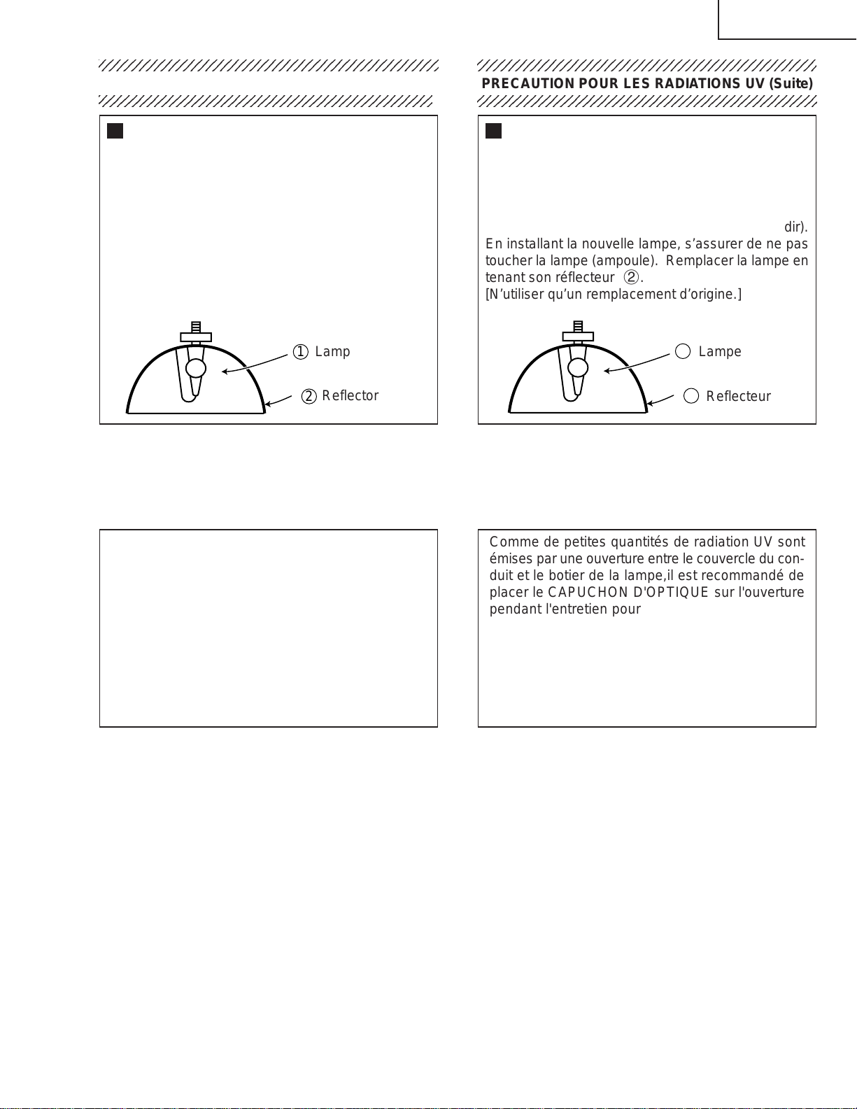
Lamp Replacement
Note:
Since the lamp reaches a very high temperature
during units operation replacement of the lamp
should be done at least one hour after the power
has been turned off. (to allow the lamp to cool off.)
Installing the new lamp, make sure not to touch the
lamp (bulb) replace the lamp by holding its reflector
2.
[Use original replacement only.]
Lamp
1
Reflector
2
DANGER ! –– Never turn the power on without the
lamp to avoid electric-shock or damage of the
devices since the stabilizer generates high voltages
at its start.
PRECAUTION POUR LES RADIATIONS UV (Suite)
234567890123456789012345678901212345678901234
Remplacement de la lampe
Remarque:
Comme la lampe devient très chaude pendant le
fonctionnement de l’unité, son remplacement ne doit
être effectué au moins une heure après avoir coupé
l’alimentation (pour permettre à la lampe de refroidir).
En installant la nouvelle lampe, s’assurer de ne pas
toucher la lampe (ampoule). Remplacer la lampe en
tenant son réflecteur 2.
[N’utiliser qu’un remplacement d’origine.]
1
Lampe
2
Reflecteur
DANGER ! –– Ne jamais mettre sous tension sans
la lampe pour éviter un choc électrique ou des
dommages des appareils car le stabilisateur génère
de hautes tensions à sa mise en route.
Since small amounts of UV-Radiation are emitted
from an opening between the duct cover and the
lamp housing, it is recommended to place the LENS
CAP on the opening during servicing to avoid eye
and skin exposure.
Note: Please obtain a lens cap before servicing a
models XV-Z90U/DT-200 that is received
without one.
Comme de petites quantités de radiation UV sont
émises par une ouverture entre le couvercle du conduit et le botier de la lampe,il est recommandé de
placer le CAPUCHON D'OPTIQUE sur l'ouverture
pendant l'entretien pour éviter une exposition des
yeux et la peau.
Remarque: Priére de se procurer un capuchon
d'optique acant d'entretien un modéle
XV-Z90U/DT-200 qui est livré sans.
5
Page 6
XV-Z90U
DT-200
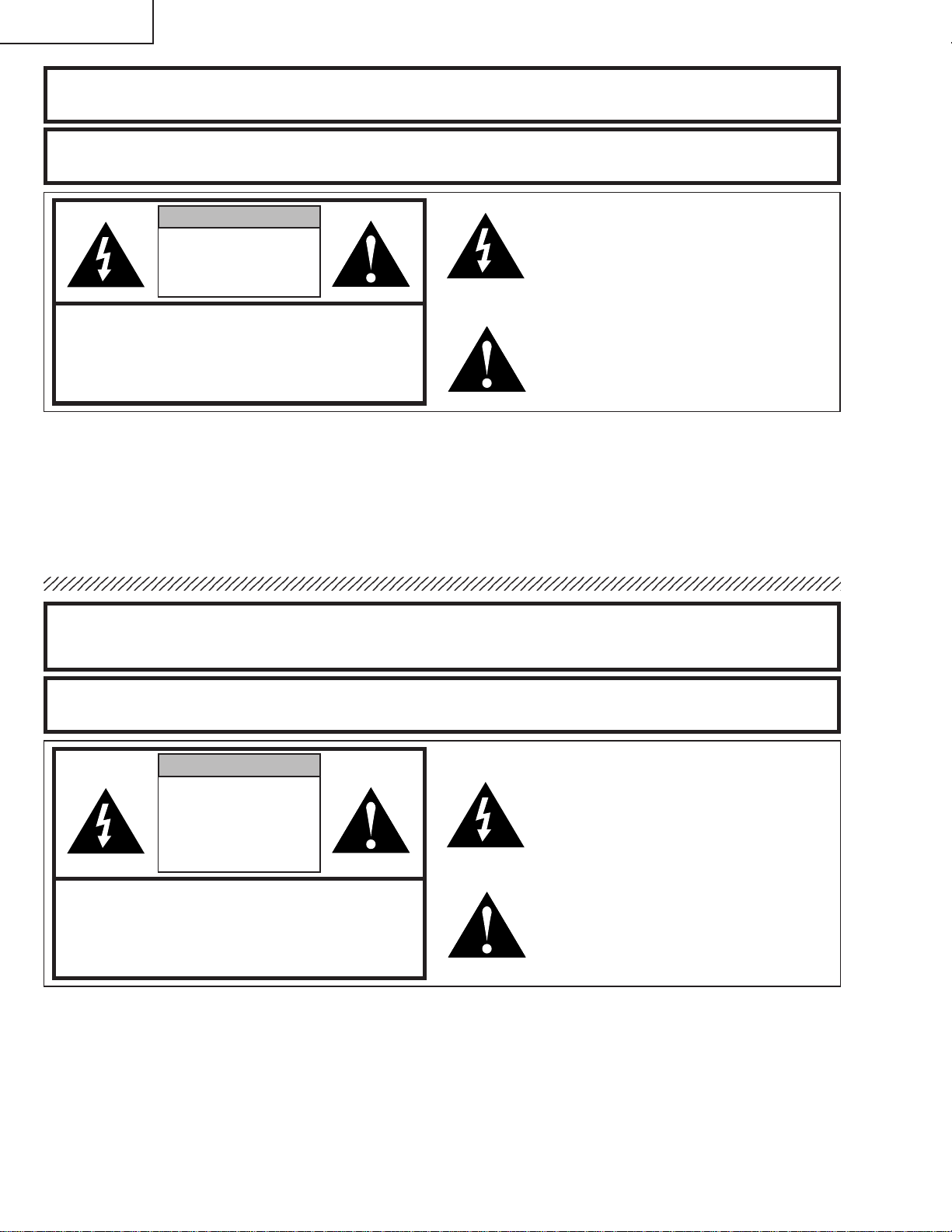
WARNING: High brightness light source, do not stare into the beam of light, or view directly . Be especially
careful that children do not stare directly in to the beam of light.
WARNING: TO REDUCE THE RISK OF FIRE OR ELECTRIC SHOCK, DO NOT EXPOSE THIS UNIT TO
MOISTURE OR WET LOCATIONS.
CAUTION
RISK OF ELECTRIC SHOCK.
DO NOT REMOVE SCREWS
EXCEPT SPECIFIED USER
SERVICE SCREWS
CAUTION: TO REDUCE THE RISK OF ELECTRIC SHOCK,
DO NOT REMOVE CABINET.
NO USER-SERVICEABLE P ARTS EXCEPT LAMP UNIT.
REFER SERVICING TO QUALIFIED SERVICE
PERSONNEL.
The lighting flash with arrowhead within
a triangle is intended to tell the user that
parts inside the product are risk of electric
shock to persons.
The exclamation point within a triangle is
intended to tell the user that important
operating and servicing instructions are
in the manual with the projector.
AVERTISSEMENT: Source lumineuse de grande intensité. Ne pas fixer le faisceau lumineux ou le regarder
directement. Veiller particulièrement à éviter que les enfants ne fixent directement le
faisceau lumineux.
AVERTISSEMENT: AFIN D’EVITER TOUT RISQUE D’INCENDIE OU D’ELECTROCUTION, NE P AS PLACER
CET APPAREIL DANS UN ENDROIT HUMIDE OU MOUILLE.
ATTENTION
RISQUE
D’ELECTROCUTION NE
PASRETIRER LES VIS, A
L’EXCEPTION DES VIS DE
REPARATION UTILISATEUR
SPECIFIEES
ATTENTION: POUR EVITER TOUT RISQUE
D’ELECTROCUTION, NE PAS RETIRER LE CAPOT.
AUCUNE DES PIECES INTERIEURES N’EST REP ARABLE
PAR L ’UTILISATEUR, A L ’EXCEPTION DE L ’UNITE DE
LAMPE. POUR TOUTE REP ARATION, S’ADRESSER A UN
TECHNICIEN D’ENTRETIEN QUALIFIE.
L’éclair terminé d’une flèche à l’intérieur
d’un triangle indique à l’utilisateur que les
pi‘eces se trouvant dans l’appareil sont
susceptibles de provoquer une décharge
électrique.
Le point d’exclamation à l’intérieur d’un
triangle indique à l’utilisateur que les
instructions de fonctionnement et
d’entretien sont détaillées dans les
documents fournis avec le projecteur.
6
Page 7
XV-Z90U
DT-200
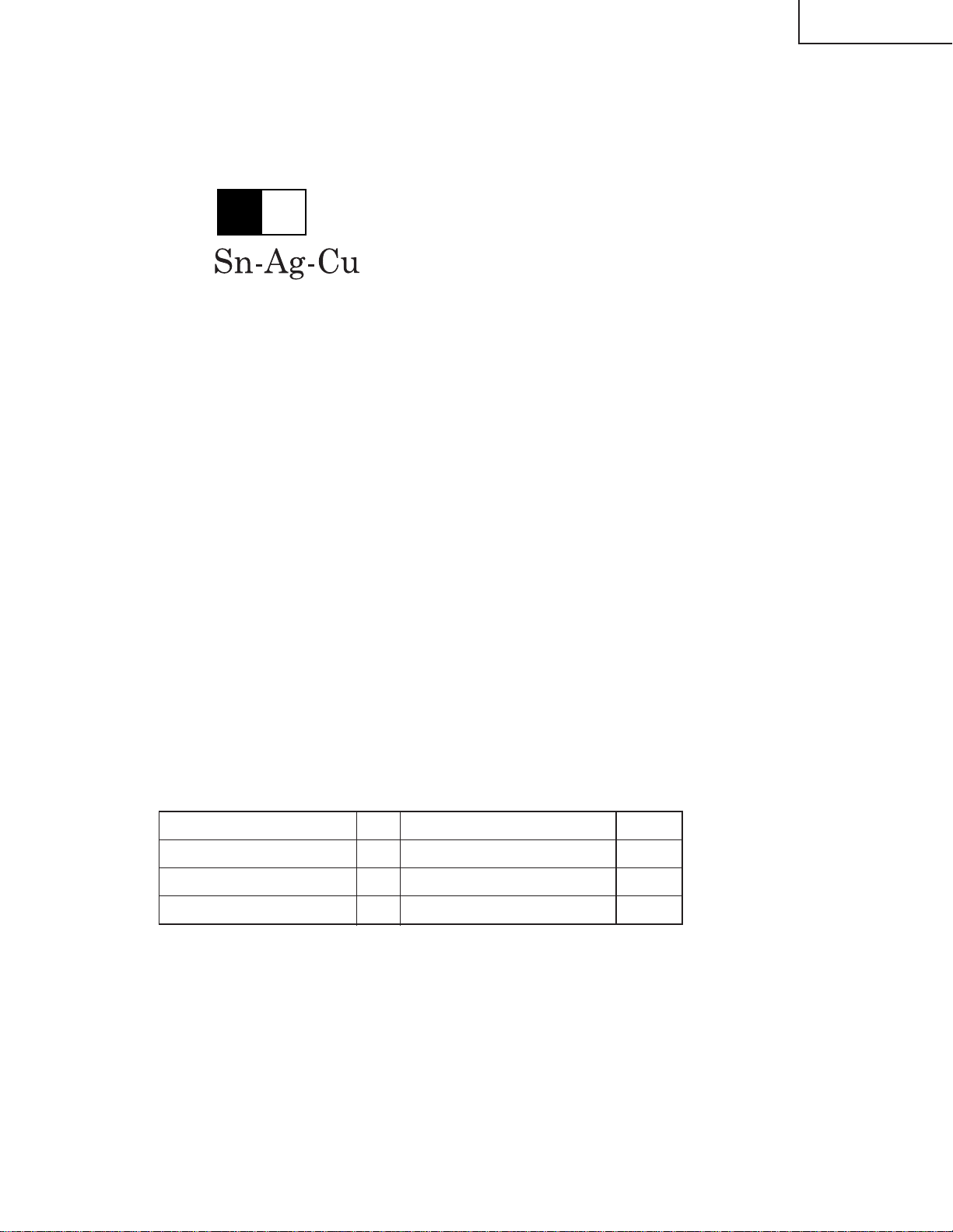
Precautions for using lead-free solder
1 Employing lead-free solder
"Front-R/C, LED, DVi-TANi, terminal 2,Rear-R/C and key PWBs" of this model employs lead-free solder. The LF
symbol indicates lead-free solder, and is attached on the PWBs and service manuals. The alphabetical character
following LF shows the type of lead-free solder.
Example:
L Fa
Indicates lead-free solder of tin, silver and copper.
2 Using lead-free wire solder
When fixing the PWB soldered with the lead-free solder, apply lead-free wire solder. Repairing with conventional
lead wire solder may cause damage or accident due to cracks.
As the melting point of lead-free solder (Sn-Ag-Cu) is higher than the lead wire solder by 40°C, we recommend you
to use a dedicated soldering bit, if you are not familiar with how to obtain lead-free wire solder or soldening bit,
contact our service station or service ranch in your area.
3 Soldering
As the melting point of lead-free solder (Sn-Ag-Cu) is about 220°C which is higher than the conventional lead solder
by 40°C, and as it has poor solder wettabillty, you may be apt to keep the soldering bit in contact with the PWB for
extended period of time. However, Since the land may be peeled of f or the maximum heat-resistance temperature of
parts may be excoeded, remove the bit from the PWB as soon as you conurm the steady soldering condition.
Lead-free solder contains more tin, and the end of the soldering bit may be easily corroded. Make sure to tum on and
off the power of the bit as required.
if a different type of solder stays on the tip of the soldering bit, it is alloyed with lead-free solder. Clean the bit after
every use of it.
When the tip of the soldering bit is blackened during use, file it with steel wool or fine sandpaper.
Becareful when replacing parts with polarity indication on the PWB silk.
Lead-free wire solder for servicing
Part No. ★ Description Code
ZHNDAi123250E J φ0.3mm 250g(1roll) BL
ZHNDAi126500E J φ0.6mm 500g(1roll) BK
ZHNDAi12801KE J φ1.0mm 1kg(1roll) BM
7
Page 8
XV-Z90U
DT-200
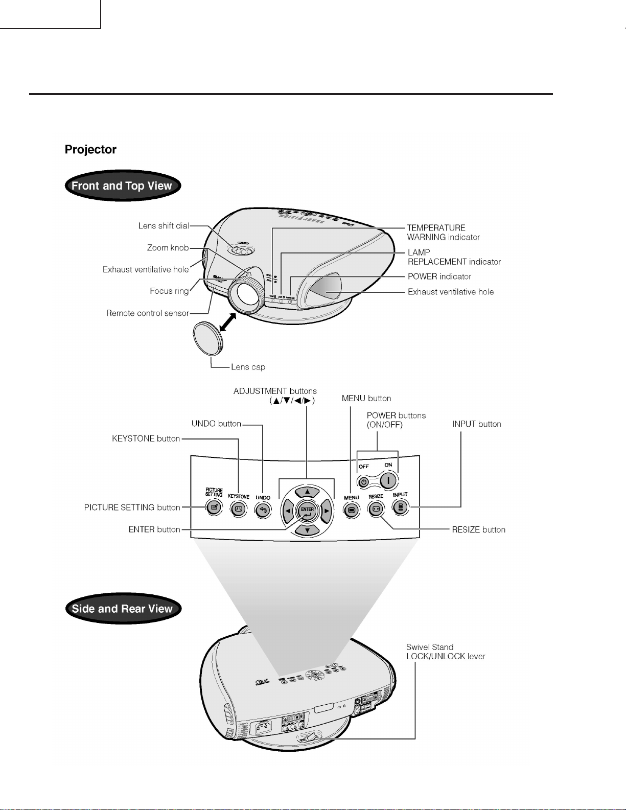
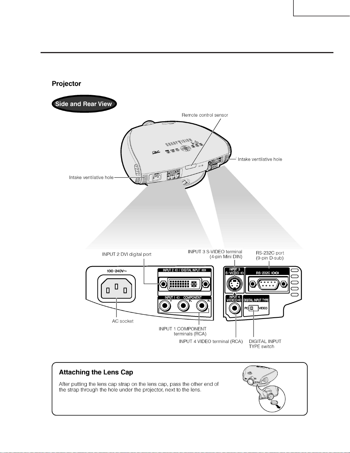
OPERATION MANUAL
Location of Controls
This illustration is XV-Z90U. A body logo is different from DT-200.
8
Page 9
XV-Z90U
DT-200
9
Page 10
XV-Z90U
DT-200
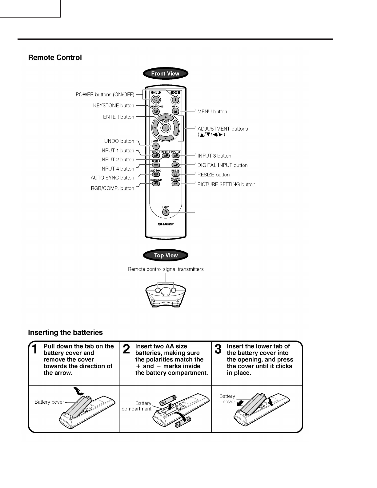
LIGHT button (XV-Z90U)
FREEZE button (DT-200)
10
Page 11
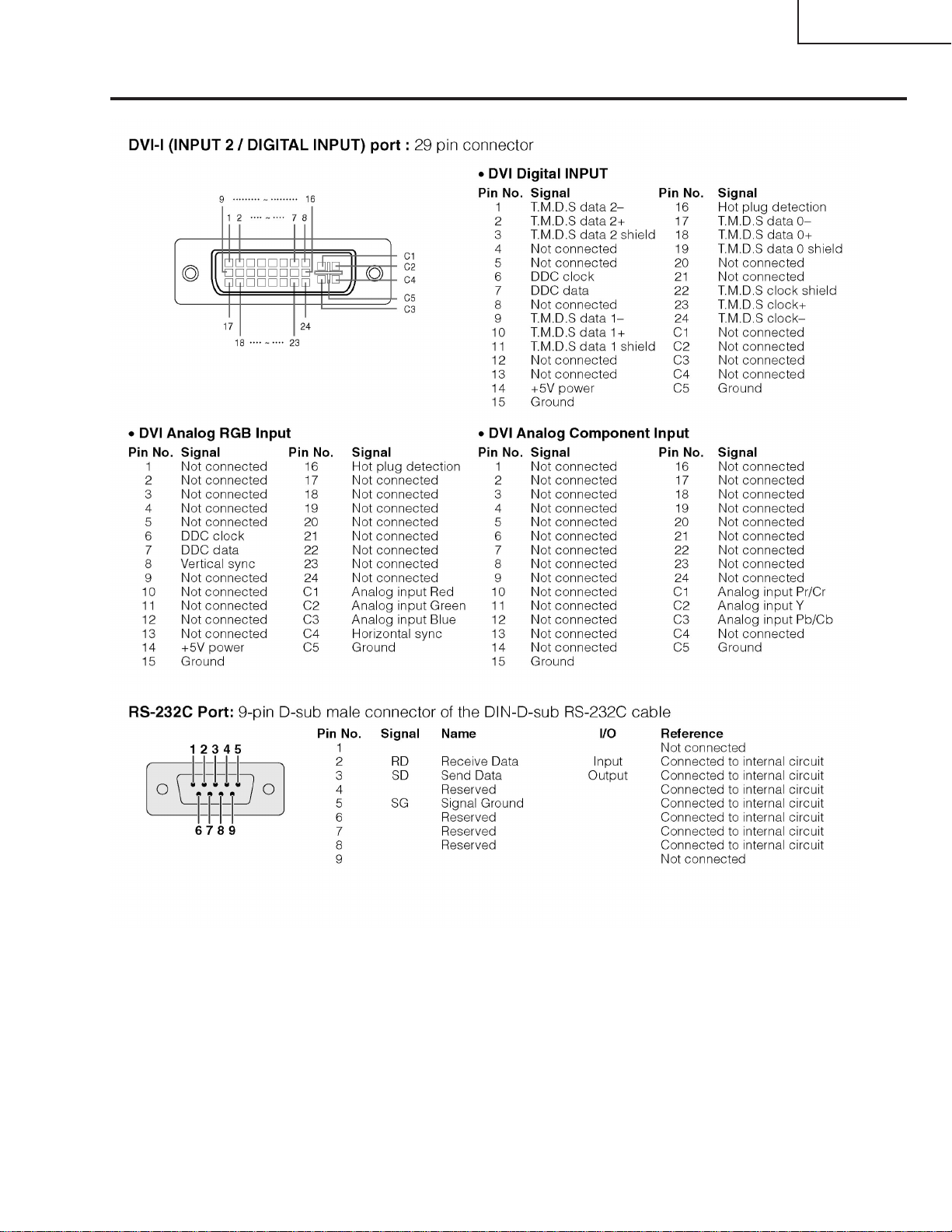
Connection Pin Assignments
XV-Z90U
DT-200
11
Page 12
XV-Z90U
DT-200
Dimensions
This illustration is XV-Z90U. A body logo is different from DT-200.
12
Units: inches (mm)
Page 13
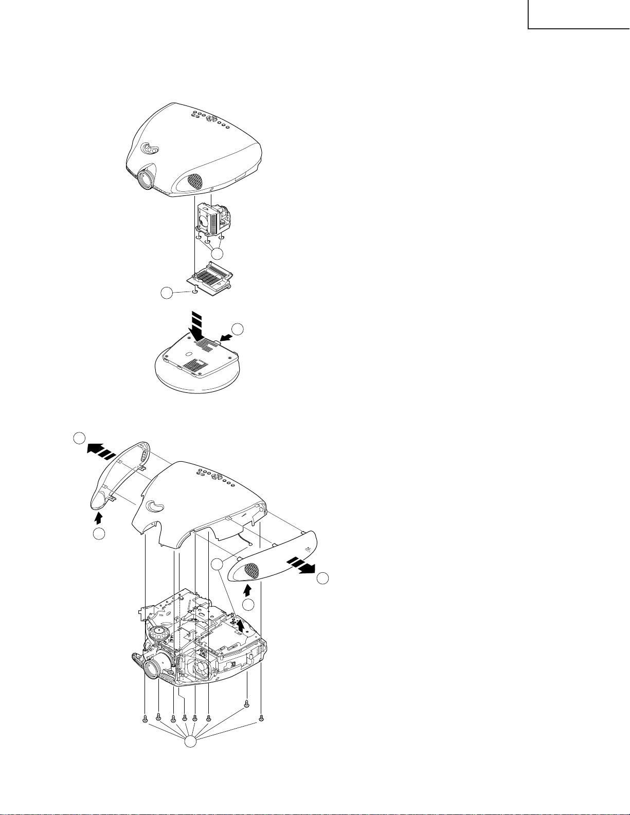
REMOVING OF MAJOR PARTS
1. Removing the swivel stand and the lamp box.
1-1. Remove lock lever, and remove the swivel stand.
1-2. Loosen 1 scrwew, and remove the lamp door .
1-3. Loosen 3 screws, and take out a lamp box.
Lamp Box
1-3
XV-Z90U
DT-200
1-2
Lamp Door
Swivwl Stand Lock Lever
1-1
Swivwl Stand
2. Removing the side covers and the top body.
2-2
Side Cover
Top Body
2-1
2-3
2-2
Side Cover
2-1
[KY]
2-1. Push front end of the side cover from bottom, and
remove a hook.
2-2. Pull the side cover in the direction of the arrow, and
remove it.
2-3. Remove 8 screws and 1connector, and remove a top
body .
2-3
13
Page 14
XV-Z90U
DT-200
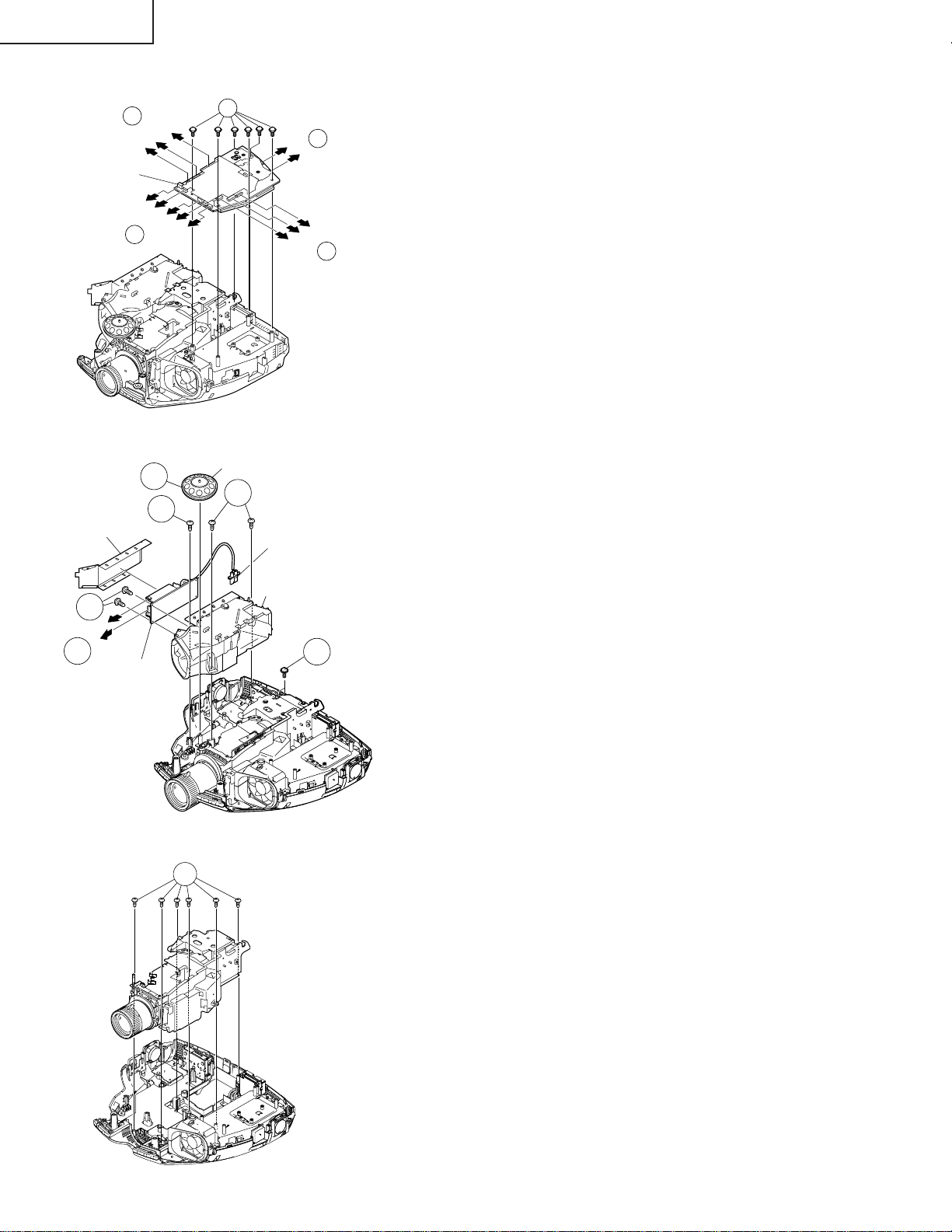
3. Removing the main PWB.
3-1
[TF]
[FA]
[FC]
Main PWB
3-2
[BA]
3-2
[FD]
[FB]
[TD]
[PG]
[DA]
[TH]
4. Removing the Ballast unit.
Lens Shift Knob
4-1
4-3
4-3
Shielding Plate
4-5
[BA]
[EC]
4-4
Ballast PWB
Ballast Socket
Exhaust Duct Unit
[ED]
[RB]
3-2
[TC]
4-2
3-1. Remove 6 screws.
3-2. Remove each connector on the main PWB.
3-2
4-1. Remove lens shift knob.
4-2. Remove 2 screws, and remove the ballast socket.
4-3. Remove 3 screws, and remove the ballast unit.
4-4. Remove shielding plate, and remove 2 connectors
on the ballast PWB.
4-5. Remove 2 screws, and remove ballast PWB.
5. Removing the optic mechanism unit.
5-1
Optic mechanism unit
5-1. Remove 5 screws, and remove the optic mechanism
unit.
14
Page 15
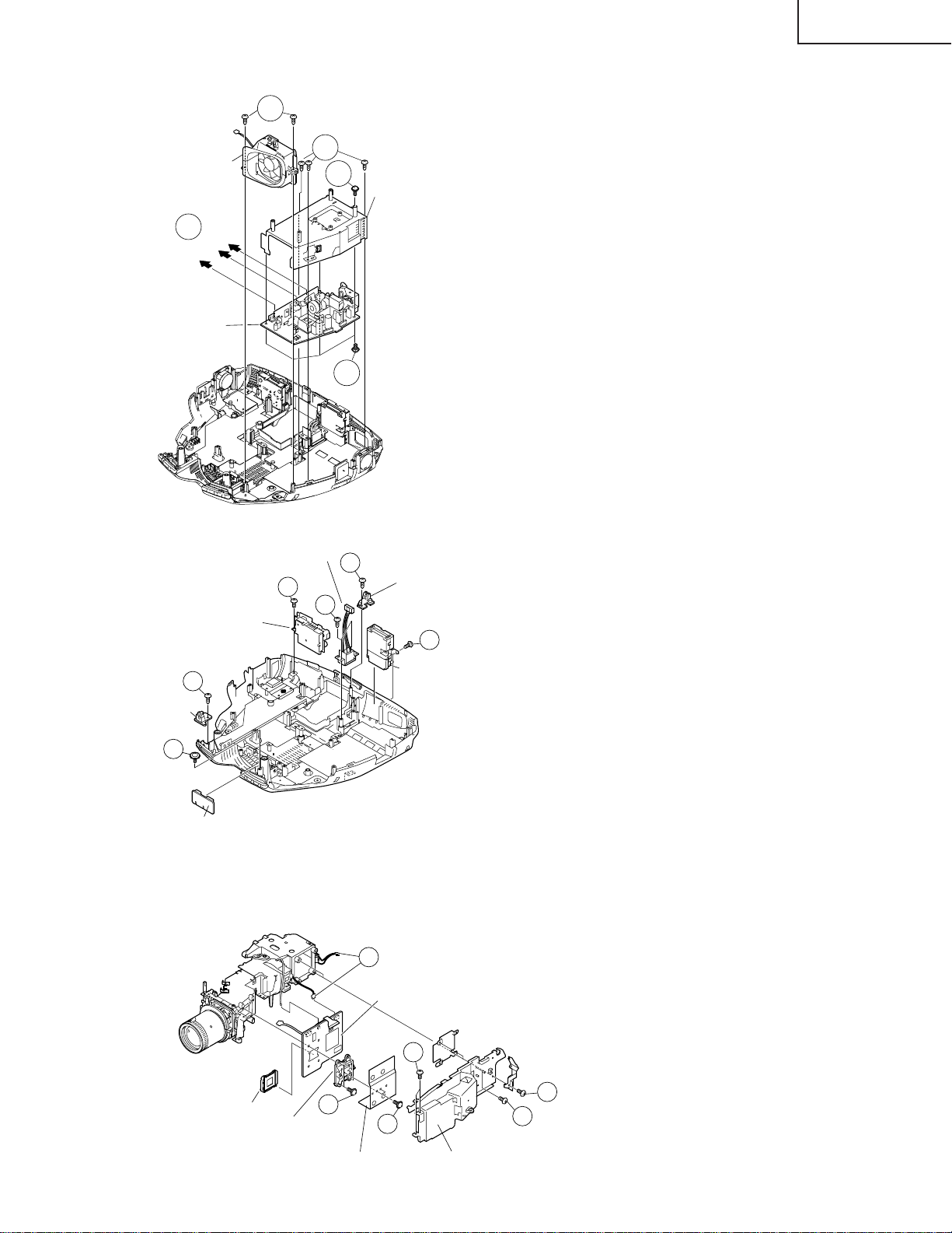
6. Removing the power unit.
6-2
Power Unit
Fan
6-1
[EA]
[EC]
Power PWB
[EB]
6-3
6-4
6-4
Power Shield
XV-Z90U
DT-200
6-1. Remove each connector on the power PWB.
6-2. Remove 2 screws, and remove the power unit fan.
6-3. Remove 3 screws, and take out the power unit as-
sembly.
6-4. Remove 5 screws, and remove power shield.
7. Removing the each other PWBs.
AC Socket
7-3
Terminal 2 PWB
7-1
Front R/C
Receiver PWB
7-2
LED PWB
7-4
7-5
Rear R/C
Receiver PWB
DVI-TAN1 PWB
8. Removing the formatter PWB.
8-4
Formatter PWB
7-6
7-1. Remove 1 screw, and remove front R/C receiver PWB
unit .
7-2. Remove 1 screw, and remove LED PWB unit.
7-3. Remove 1 screw, and remove a terminal-2 PWB unit.
7-4. Remove 2 screws, and remove an AC socket.
7-5. Remove 1 screw, and remove rear R/C receiver PWB
unit.
7-6. Remove 1 screw, and remove DVI-TAN1 PWB unit.
8-1. Remove 2 screws, and remove the angle.
8-2. Remove 3 screws, and remove the blower fan unit.
8-3. Remove 2 screws, and remove the heat sink.
8-4. Remove 4 screws and two connectors, and remove
the formatter PWB.
DMD
Backer Plate
8-4
Heat Sink
8-3
8-2
8-1
8-2
Blower Fan Unit
15
Page 16
XV-Z90U
DT-200
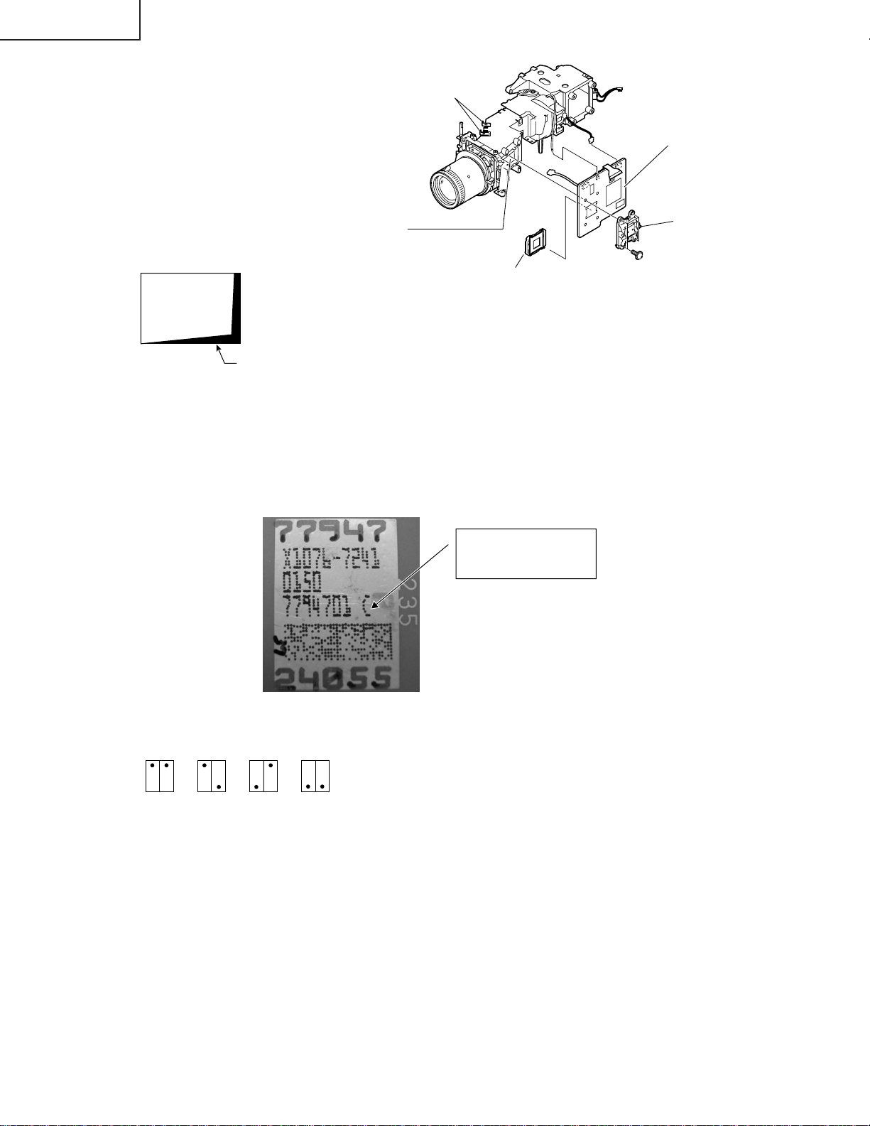
Precautions in replacing the DMD chip
Note: Be careful not to allow dust and fingerprint
Mirror adjusting plate
on the cover glass of DMD chip and prism
surface of optical engine.
1. When you fix 4screws of backer plate assembly,
press backer plate to formatter PWB and fix by
Formatter PWB
cross multiply step by step.
2. If something shade appears on the projection
screen like Fig1, release 2 screws on mirror
adjusting plate and move that plate to adjust
Prism surface
Backer Plate
illumination area of DMD chip.
DMD
(Digital Micromirror
Device) chip
+Outer Frame
+ C-Spring
Fig.1
Shade
* Precautions in setting up the DMD (Digital Micromirror Device) unit
Before connecting the formatter PWB to the optical engine, take the following steps. Look at the voltage rank marking
that is on the DMD itself. Referring to this marking, set the DIP switches on the formatter PWB. And connect this PWB
to the optical engine. Wrong settings will adversely affect the system performance.
Voltage ranking system with the switch switches on formatter PWB
BCDE
Voltage rank marking
This sample is "C".
16
Page 17
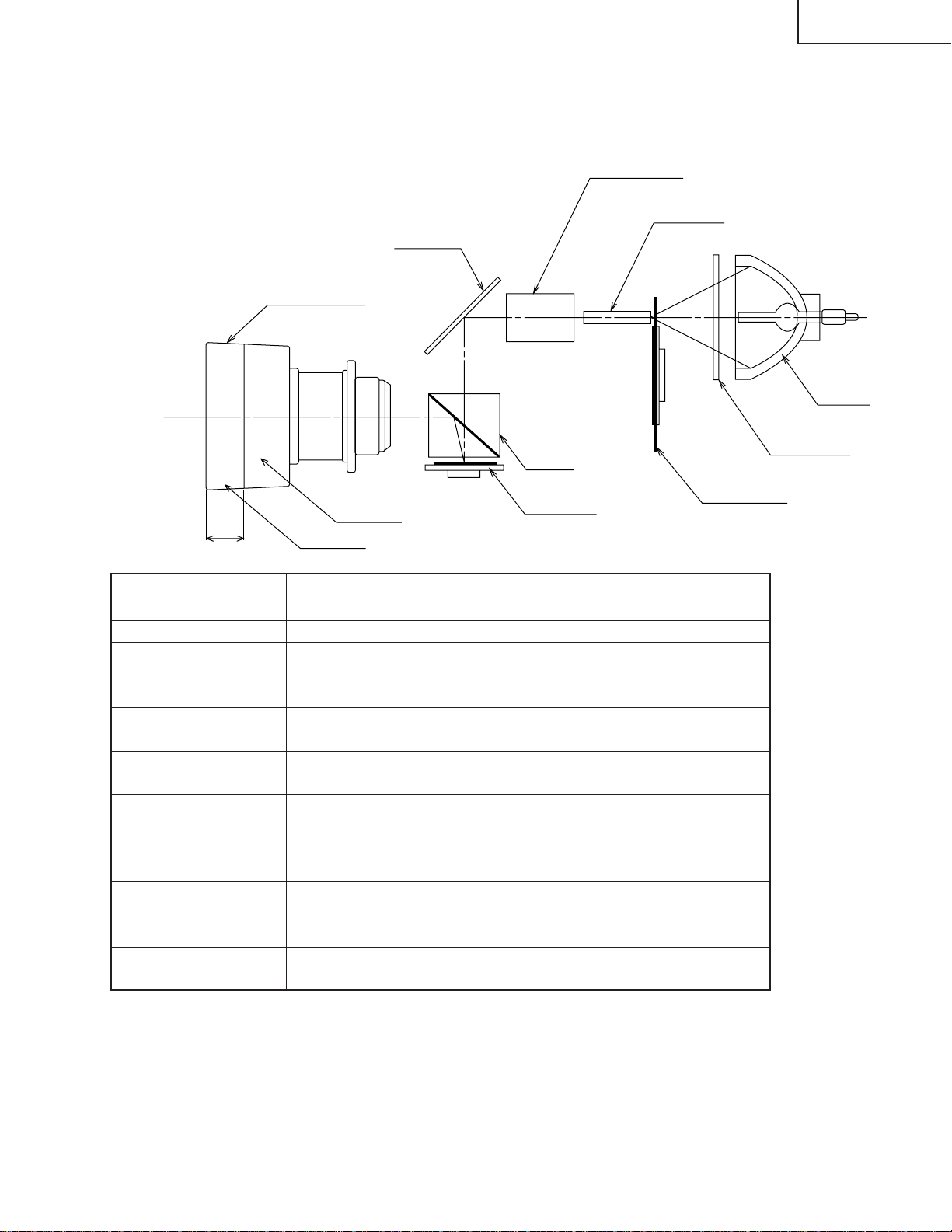
Outline of the optical unit
<Layout>
Projection lens
XV-Z90U
DT-200
Relay lenses
Rod lens
Reflector
Lamp
UV/IR filter
Prism
Width
Item
Lamp
UV/IR filter
Color wheel
Rod lens
Relay lenses
Reflector
Prism
DMD chip
Projection lens
Color wheel
Zoom ring
Focus ring
DMD chip
Function
Light source. DC-driven high-pressure mercury vapor lamp.
Used to absorb ultraviolet and infrared rays.
Used to let the source light through the color filter and to
separate it into R, G and B colors.
Used to make for uniform light beams.
Used to collect the light from the rod lens into the DMD
chip.
Used to reflect the light from the relay lenses against the
DMD chip.
Used to introduce the light from the reflector over the effective surface of the DMD chip. When the micromirror gets
tilted (ON) as specified, the reflected light is guided to the
projection lens.
Used to turn on and off the micromirror in response to the
ratio of color components at each dot and thus to reflect the
incoming light accordingly.
Used to enlarge the light from the DMD chip and to get the
light projected on the screen.
Distinction between long and short focal length lens
• Long focal length lens: focus ring width: about 18 mm | XV-Z90U
• Short focal length lens: focus ring width: about 27 mm | DT-200
Caution when repairing without top cabinet
To repair this set without top cabinet, attach the left side body beforehand. (Since the exhaust heat gets in around the
set and the temperature sensor detects it giving the TEMP error and the lamp goes off.)
17
Page 18
XV-Z90U
DT-200
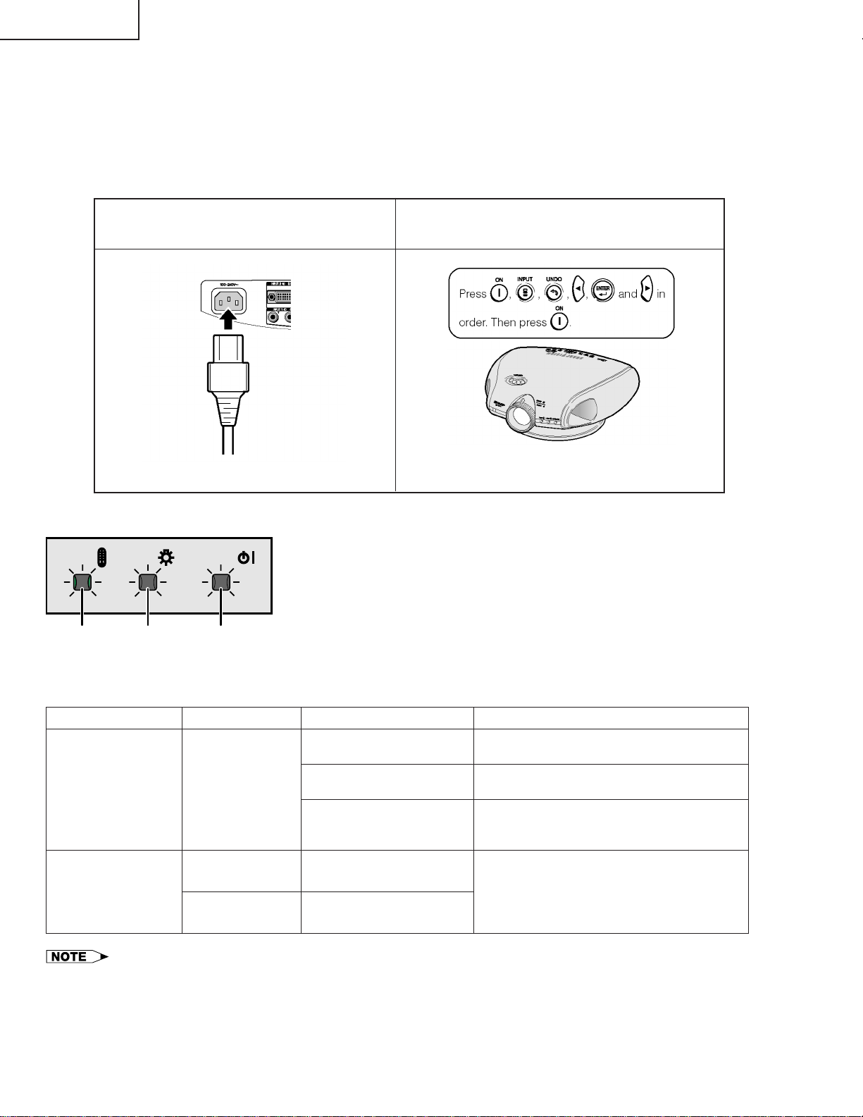
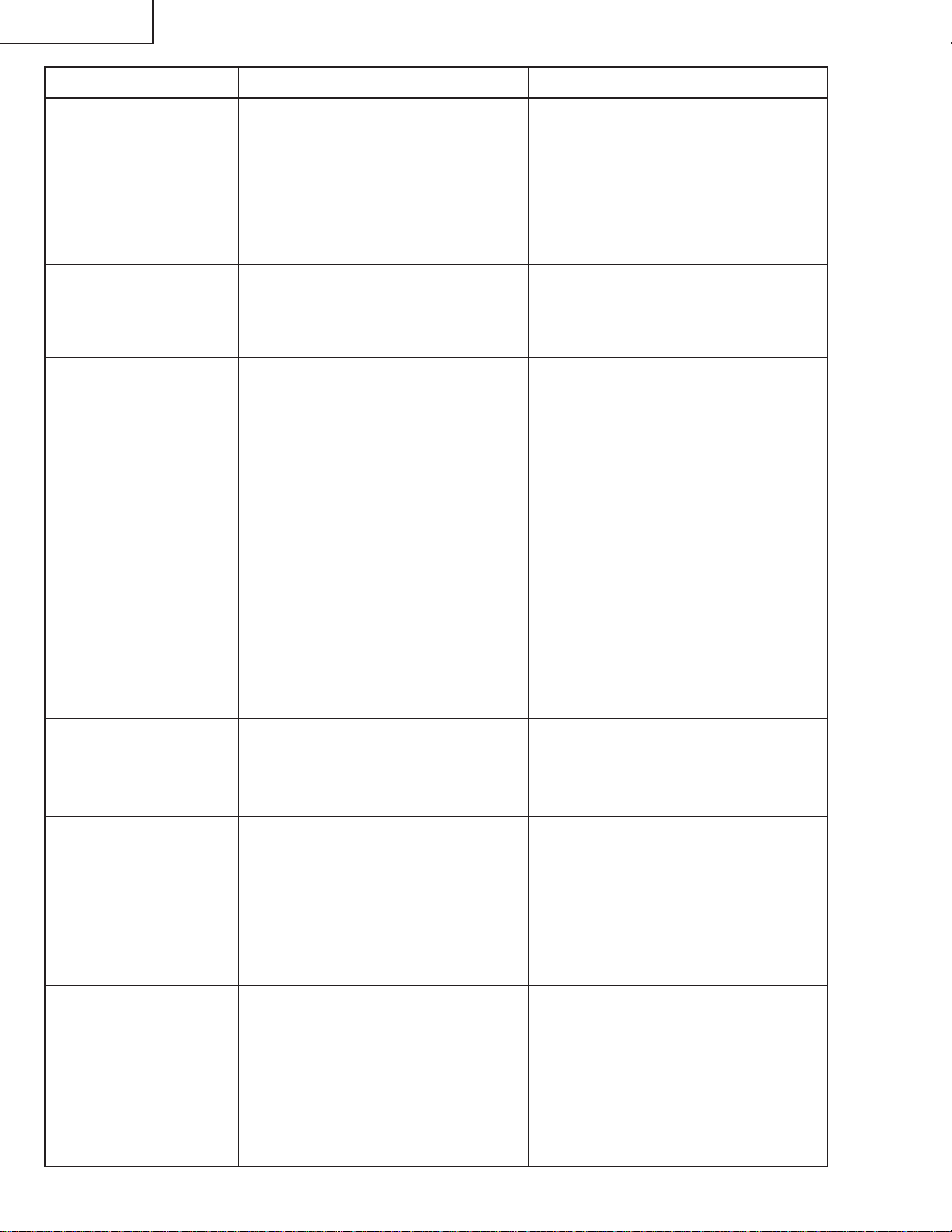
RESETTING THE TOTAL LAMP TIMER
You need to reset the lamp timer every time you replace the lamp and confirm it is reset on the
“Lamp Timer” menu.
How to reset the total lamp timer.
1. Plug the power cord 2. Press POWER ON on the projector to reset the lamp timer.
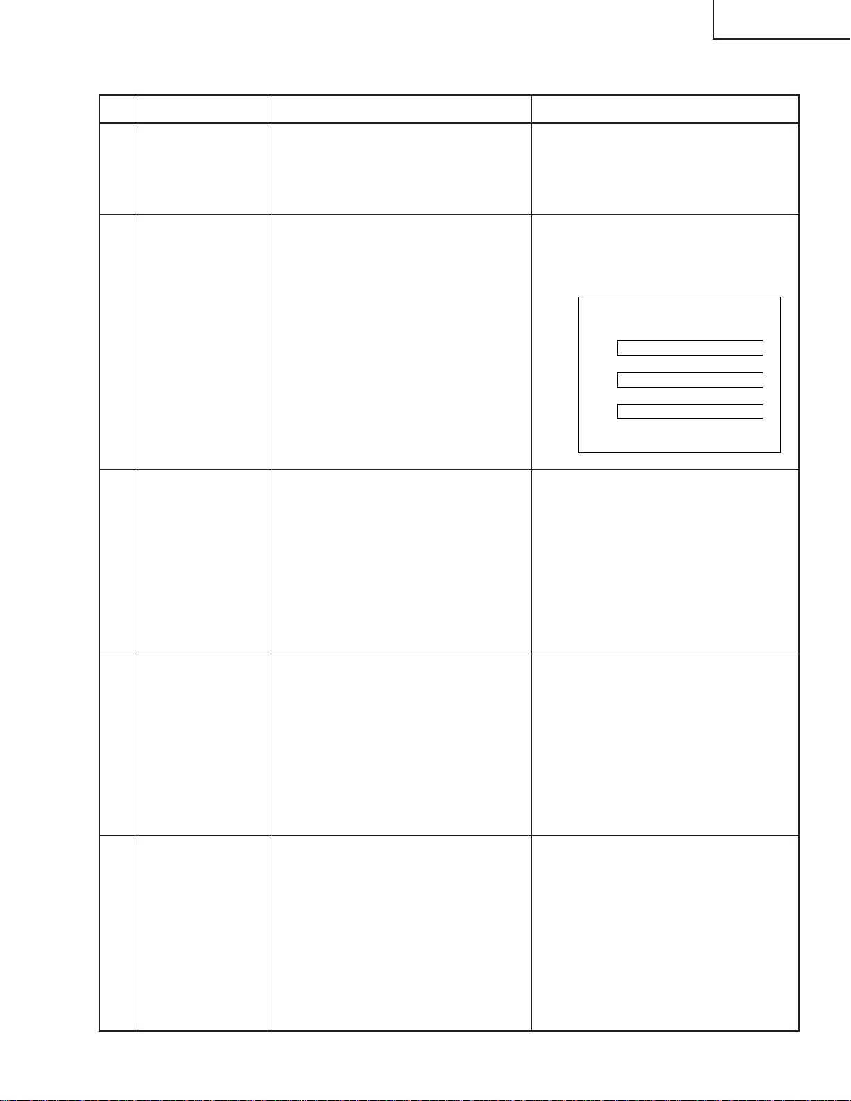
Maintenance Indicators
TEMP. LAMP POWER
TEMPERATURE
WARNING
indicator
Maintenance Indicator
TEMPERATURE W ARNING indicator
LAMP REPLACEMENT
indicator
LAMP
REPLACEMENT
indicator
POWER
indicator
Condition
The internal temperature is abnormally high.
The lamp does not light
up.
The lamp requires replacement.
“LAMP 0000H” is displayed on the
screen.
• The warning lights on the projector indicate problems
inside the projector.
• There are two types of warning lights: a TEMPERATURE
WARNING indicator that warns you when the projector
is too hot, and a LAMP REPLACEMENT indicator that
warns you when to change the lamp.
• If a problem occurs, either the TEMPERATURE WARNING indicator or the LAMP REPLACEMENT indicator
will illuminate in red. After turning off the power, follow
the procedures given below.
Problem
• Blocked air intake.
• Clogged ventilative hole.
• Cooling fan breakdown.
• Internal circuit failure.
• Burnt-out lamp.
• Lamp circuit failure.
• Lamp has been used for over
2,400 hours.
Possible Solution
• Relocate the projector to an area with proper ventilation.
• Clean the ventilative holes.
• Take the projector to your nearest Authorized
SharpVision Service Center or Dealer for repair.
• Carefully replace the lamp.
• Take the projector to your nearest Authorized
SharpVision Service Center or Dealer for repair.
• If the TEMPERATURE WARNING indicator lights up, follow the above possible solutions and then wait until the
projector has cooled down completely before turning the power back on. (At least 5 minutes.)
• If the power is turned off and then turned on again, for example during a brief rest, the may be triggered,
preventing the power from going on. Should this occur, unplug the power cord from the wall outlet and plug it
back in again.
18
Page 19
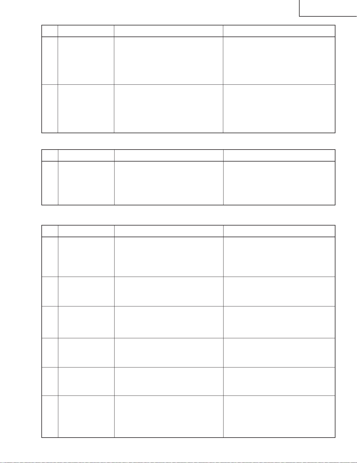
ELECTRICAL ADJUSTMENT
No. Adjustment Items Adjustment Conditions Adjustment Procedures
XV-Z90U
DT-200
1 Initialization of
EEPROM
2 Adjustment of CW
index
3-1 Adjustment of R
brightness/contrast
1. Turn on the power (the lamp lights
up) and warm up the system for 15
minutes.
1. Input the gradation pattern of RGB.
2. Select the following group and subject.
Group: DLP
Subject: Select CW-INDEX.
1. Select the following group and subject.
Group: AD
Subject: R-Bright
R-Contrast
2. Feed the window pattern having
91%(0.64Vp-p) R signal and 0%.
(Process gamma interlock)
1. Carry out the following setting.
Using the remote controller or press
S2002 to enter the process mode,
and execute SS2 on SS menu.
1. Select subject and make adjustment
so that the lamp gradation patterns
of R, G and B should be smooth without noise.
R
G
B
1. On the bit-less screen, adjust in the
order of black side R-bright and white
side R-contrast.
Adjust the black level so that bright
red bit-less may disappear and may
turn pale red.
Adjust the white level so that red bitless may appear from black.
3-2 Adjustment of G
brightness/contrast
3-3 Adjustment of B
brightness/contrast
1. Select the following group and subject.
Group: AD
Subject: G-Bright
G-Contrast
2. Feed the window pattern having
91%(0.64Vp-p) G signal and 0%.
(Process gamma interlock)
1. Select the following group and subject.
Group: AD
Subject: B-Bright
B-Contrast
2. Feed the window pattern having
91% (0.64Vp-p) B signal and 0%.
(Process gamma interlock)
1. On the bit-less screen, adjust in the
order of black side G-bright and white
side G-contrast.
Adjust the black level so that bright
green bit-less may disappear and
may turn pale green.
Adjust the white level so that green
bit-less may appear from black.
1. On the bit-less screen, adjust in the
order of black side B-bright and white
side B-contrast.
Adjust the black level so that bright
blue bit-less may disappear and may
turn pale blue.
Adjust the white level so that blue
bit-less may appear from black.
19
Page 20
XV-Z90U
DT-200
No. Adjustment Items Adjustment Conditions Adjustment Procedures
4 Adjustment of
DTV brightness/
contrast
5 Adjustment of
DTV tint
6 Adjustment of
DTV color saturation
7 Adjustment of
DVD brightness/
contrast
1. Feed 480P 100% Black/White window pattern signal.
2. Select the following group and subject.
Group: DTV
Subject: Bright
Contrast
(Process gamma interlock)
1. Select the following group and subject.
Group: DTV
Subject: Tint
1. Select the following group and subject.
Group: DTV
Subject: Color
1. Feed 480I 10STEP signal (without
setup).
2. Select the following group and subject.
Group: DVD
Subject: Bright
Contrast
(Process gamma interlock)
1. On the bit-less screen, adjust in the
order of black side Bbright and white
side Contrast.
Adjust the black level so that bright
green bit-less may disappear and
may turn pale green.
Adjust the white level so that bit-less
may appear from black.
1. Confirm the fixed value.
Tint: 8
1. Confirm the fixed value.
Color: 13
1. On the bit-less screen, adjust in the
order of black side Bbright and white
side Contrast.
Adjust the black level so that bright
green bit-less may disappear and
may turn pale green.
Adjust the white level so that bit-less
may appear from black.
8 Adjustment of
DVD tint
9 Adjustment of
DVD color saturation
10 Adjustment of
Video brightness/
contrast
11 Adjustment of
Video tint
1. Select the following group and subject.
Group: DVD
Subject: Tint
1. Select the following group and subject.
Group: DVD
Subject: Color
1. Feed NTSC 10STEP signal (without setup).
2. Select the following group and subject.
Group: VIDEO
Subject: Bright
Contrast
(Process gamma interlock)
1. Select the following group and subject.
Group: VIDEO
Subject: N-Tint
P-Tint
S-Tint
1. Confirm the fixed value.
Tint: 8
1. Confirm the fixed value.
Color: 10
1. Adjust the setting value of Bright become the same as DVD-Bright.
2. On the bit-less screen, adjust in the
order of black side Bbright and white
side Contrast.
Adjust the white level so that bit-less
may appear from black.
1. Confirm the fixed value.
N-Tint: 8
P-Tint: 8
S-Tint: 8
20
Page 21
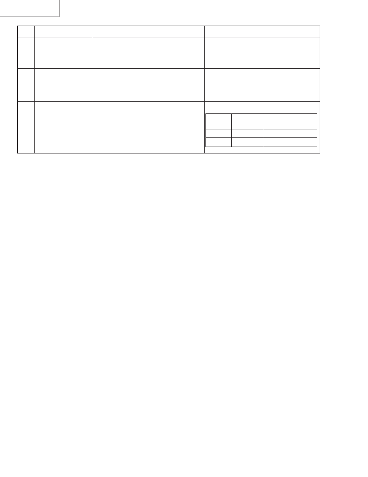
No. Adjustment Items Adjustment Conditions Adjustment Procedures
XV-Z90U
DT-200
12 Adjustment of
Video color
saturation
13 Adjustment of
DTV white balance
1. Select the following group and subject.
Group: VIDEO
Subject: N-Color
P-Color
S-Color
1. Feed 480I75% gray signal.
2. Select the following group and subject.
Group: DLP
Subjects: R-Contrast(R)
B-Contrast(B)
1. Confirm the fixed value.
N-Color: 10
P-Color: 10
S-Color: 10
1. Confirm the fixed value.
R-Contrast
B-Contrast
(x=289, y=323)
Adjustment when assembling
No. Adjustment Items Adjustment Conditions Adjustment Procedures
14 Adjustment of
DLP voltage
(Reference)
1. Read voltage rank of DLP description.
2. Set the switch corresponding to the
rank which has been read. (on the
formatter PWB)
1. Carry out adjustment when DLP chip
has been replaced or combination of
chip and formatter has been changed.
2. Rank: BCDE
Setting value: 1234
Confirmation
No. Adjustment Items Adjustment Conditions Adjustment Procedures
15 Check and re-
adjustment of the
white balance
16 Confirmation of
color-related
operation
17 Confirmation of
picture-related
operation
18 Confirmation of
RGB
19 Confirmation of
DVI digital
The adjustment conditions of the item
13 for the DTV input.
1. Receive the color bar signal. 1. Select L1 in the process mode.
1. Receive monoscope pattern signal. 1. Select L2 in the process mode.
1. Receive the RGB signal. 1. Select L4 on the process mode.
1. Receive the digital signal. 1. Confirm that the picture is outputted.
Check that the white balance is in the
best condition.
In case to re-adjust, carry out DVD input only.
Check the performance of color and
tint.
Check Picture, Brightness and Sharpness.
Check Picture, Brightness, Red, Blue,
Clock, Phase, H-POS and V-POS.
20 Confirmation of
off-timer operation
1. Select OFF in the process mode.
Confirm that the off-timer starts with
5-minute display , counts 1 minute for
1 second, and turns off when 0 minute
is displayed.
21
Page 22
XV-Z90U
DT-200
No. Adjustment Items Adjustment Conditions Adjustment Procedures
21 Confirmation of
thermistor opera-
1. Heat the thermistor by dryer.
1. Confirm that the temperature is displayed.
tion
22 Automatic sync
operation
1. Receive the phase checking pattern
signal.
1. Confirm that Clock, Phase, H-POS
and V-POS can be automatically
adjusted in the VGA/S-VGA/XGA
mode.
23 Factory settings 1. Make the following settings.
Model Process Remote controller
adjustment settings
XV-Z90U SS4 "Factory Setting 4"
DT-200 SS5 "Factory Setting 5"
22
Page 23
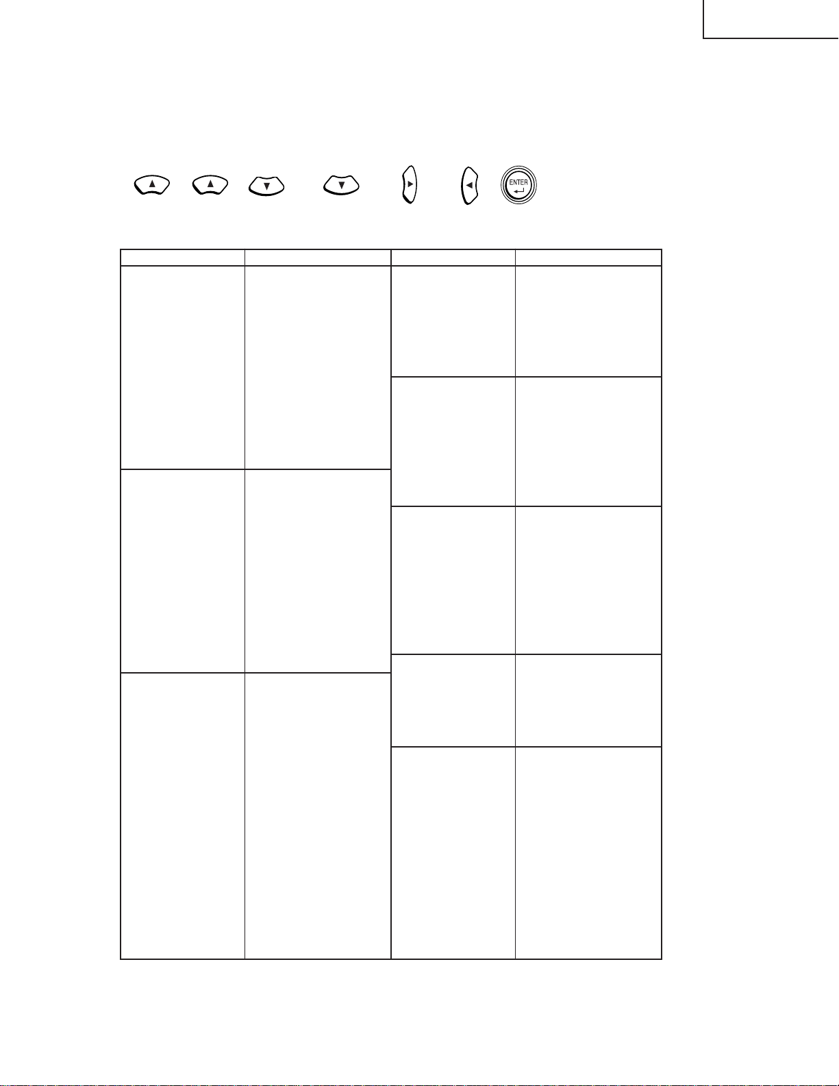
» Entering the adjustment process mode
There are following two mothods.
» Press the SW2002 on the MAIN PWB.
» Press the following keys in this order.
Adj up→Adj up→Adj down→Adj down→Adj right→Adj left→Enter
» Adjustment mode process menu
XV-Z90U
DT-200
Group Subject
DTV Contrast
Tint
Color
Sharpness
CTI-Level
LTI-Level
CB-Offset
CR-Offset
Bright
B-DRIVE
R-DRIVE
DVD Contrast
Tint
Color
Sharpness
CTI-Level
LTI-Level
CB-Offset
CR-Offset
Bright
B-DRIVE
R-DRIVE
VIDEO Contrast
N-Tint
P-Tint
S-Tint
N-Color
P-Color
S-Color
Sharpness
CTI-Level
LTI-Level
CB-Offset
CR-Offset
Bright
B-DRIVE
R-DRIVE
Group Subject
AD R-Bright
R-Contrast
G-Bright
G-Contrast
B-Bright
B-Contrast
DLP Index Delay
R-Bright
R-Contrast
G-Bright
G-Contrast
B-Bright
B-Contrast
VIDEO1 N-Contrast
P-Contrast
S-Contrast
Color
NT3.58 Delay
NT4.43 Delay
PAL Delay
SECAM Delay
VIDEO2 SS-Cont1
SS-C0nt2
Color
SS1 Delay
SS2 Delay
Pedestal R-Bright
R-Contrast
G-Bright
G-Contrast
B-Bright
B-Contrast
23
Page 24
XV-Z90U
DT-200
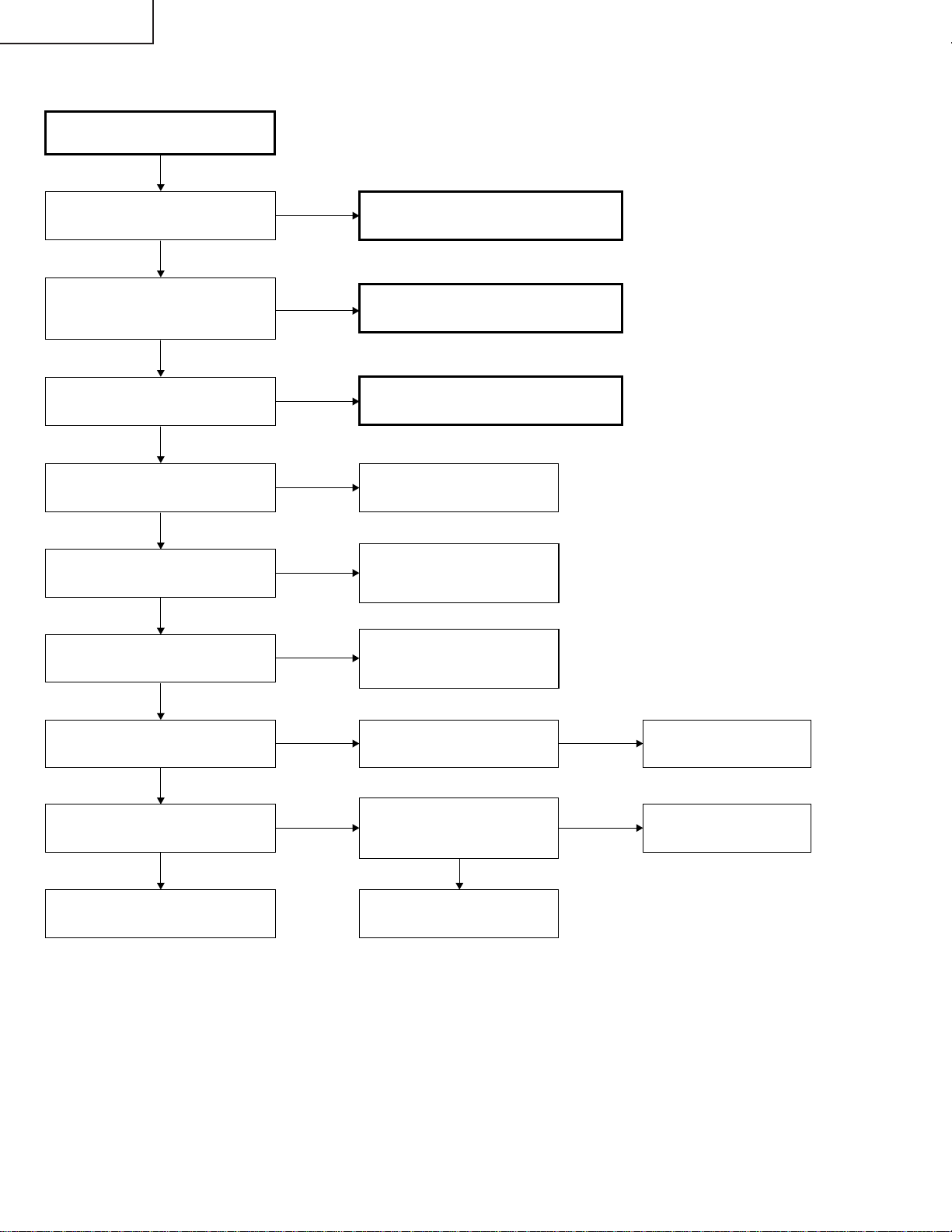
Checking of Basic Operation
TROUBLE SHOOTING TABLE
Does the POWER LED light up or
flicker in red or green?
Yes
Does the set operate by the set's
key or the remote controller's
power key?
Yes
Does the cooling fan rotate and
does the lamp light up?
Yes
Is the user menu displayed?
Yes
Is the analog RGB input acting
normally?
Yes
Does the digital RGB input
operate normally?
Yes
No
No
No
No
No
No
Go to "Checking of Power Unit".
Go to the "Check of IC2002 and
around I/O".
Go to "Checking of Lamp Lighting-up"
Check the formatter circuit and
its periphery.
Check of IC6004 (AD) or
IC3104 and check of analog
RGB input
Check of IC502 of the DVITAN1 PWB and peripheral
circuits.
Is the component input acting
normally?
Yes
Does the video input operate
normally?
Yes
End
No
No
Is there input signal at pins
(16), (18) and (20) of IC3104?
Go to "Checking of Video
Input". Is the input signal of
IC3105 coming?
Yes
Check IC3102 and its
peripheral circuit.
No
No
Check IC3104 and its
peripheral circuit.
Check IC3105 and its
peripheral circuit.
24
Page 25
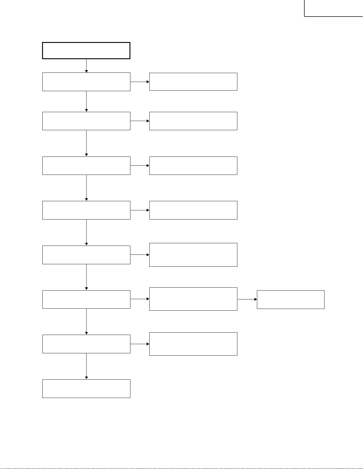
Checking of Power Unit
XV-Z90U
DT-200
Are connectors in the power unit
completely inserted?
Yes
Is the lamp door closed
completely?
Yes
Is the bimetal switch not cut?
Yes
Is AC voltage applied to AC input
both ends of D7001?
Yes
Is DC voltage about 6V on C7105
both ends?
Yes
No
No
No
No
No
Securely insert each connector.
Close the lamp door completely by
screws.
Replace the bimetal switch or
press the red button to recover.
Replace F7001.
Replace if any other damages, etc.
Check around IC7003 of the
primary side and D7103.
Replace if any damages, etc.
Is voltage about 360 V DC on the
cathode of D7004?
Yes
Is there rated voltage at the output
terminals of CN7101 and CN7102?
Yes
Check the PWB circuits of relevant
output sides.
No
No
Check the primary side circuit of
IC7001, etc. Replace if any
damages, etc.
Check the secondly side circuit of
T7001, etc. Replace if any
damages, etc.
25
No
Replace the ballast power
source side.
Page 26

XV-Z90U
DT-200
Lamp does not light up.
Yes
Is the cooling fan rotating?
Yes
Is the color wheel rotating sound
heard?
Yes
Is the lamp discharging sound
heard?
No
No
No
Yes
Check the power circuit or the fan
circuit of the main circuit.
Check around IC9101 circuit, motor
driver IC and IC9102, 9003.
Replace the color
wheel.
Normal Abnormal
Check the
formatter PWB.
Check the socket
No
Replace the lamp.
Is DC 340V voltage applied across
the ballast power?
Yes
Lamp failure to light up. Go to
"Formatter Unit Troubleshooting".
No
Is the P1701 (22) pin H level?
Check the control line P-SAVE.
Yes
Is the level converted at IC8001,
B5 output, RN4904?
No
Yes
No
Check the power circuit.
Check IC8001 and the
peripheral circuit.
26
Page 27

No
Yes
Does POWER LED flicker in red ?
Yes
Turn on the power again.
Yes
Is P1701 (9) pin (P CON0) H?
Is the FAN voltage supplied?
No
Is it in the stand-by due to
an error?
No
This is the failure of
IC2002.
Yes
FAN_ERROR is being detected.
Check around Q1701 and around
IC2002 (21) pin.
Yes
No
No
No
Is 13 V outputted to P1701 (17)
(18) (19) pins?
Go to "Checking of Power Unit"
Check IC1708, IC1710 and
around these ICs.
Yes
No
Is BU 5 V outputted from
IC1701?
Yes
Is Bu+6.5V outputted to P1701
(12) (13) (14) pins?
Check IC1701 and its
periphery."
Yes
No
Is BU 3.3 V outputted from
IC1702?
Check IC1702 and its
periphery.
Check IC1703 and its
periphery.
Yes
No
Is BU 2.5 V outputted from
IC1703?
Check IC8001 and the circuit
around the IC.
Check of IC2002 and around I/O
XV-Z90U
DT-200
27
Page 28

XV-Z90U
DT-200
Checking of SOG Circuit
Measure the (7) pin of IC5012
with an oscilloscope.
Is the composite synchronized
signal regenerated at proper timing?
No
Measure the (7) pin of IC5010
with an oscilloscope.
Is there the Y signal including sync
signal?
Yes Yes
This is the failure of the SOG
synchronization separator circuit.
Check of the S terminal input.
Input the S terminal (Y, C) signal to
INPUT 3. Select INPUT 3 with the
keys on the main body or the
remote controller.
Yes
No
The SOG circuit is normal.
End.
Is there output of the (25) pin
of IC3102?
No
Check around Q5002.
Does the picture appear? Is the picture disturbed? End.
No Yes
Is the picture signal inputted to the
connector TC (5) (7) pins?
No
Check the input side PWB .
Memo
Only in case of N358, the noise reduction
function of IC3505 is used and the noise is
reduced, so it is inputted to IC3105 (5), (7).
Yes No
1
Yes
In the picture signal inputted to
IC3105 (43) (44) pins?
Yes
Is the signal N358?
Yes
Check IC3505 and the
peripheral circuits of the IC.
No
No
28
Check the Y, C signal
lines.
Check IC3105 and the
peripheral circuits of the
IC.
Page 29

Checking of Video Input
Feed the composite video signal to
INPUT 4. Select INPUT 4 using the
set's key or the remote controller.
Does the picture appear? Is the picture disturbed?
No
Yes
End.
No
Yes
XV-Z90U
DT-200
1
Is synchronized signal
coming to IC3102 (28) (29)
pins?
Is the picture signal inputted to the
connector TC (9) pin?
Yes
Is the picture signal inputted to the
(1) pin of IC3105?
Yes
Is it N358 signal?
No
Is it PAL?
No
Is it SECAM?
No
Check the color system, around IC3105. Others.
Is input coming to IC3104 (1) (3) (5)?
No
No
Yes
Yes
Yes
Check the TERMINAL2 PWB.
Check the VIDEO-IN signal
line of IC3503.
Check around IC3501, 3505.
Check around IC3504, 3506.
Check around IC 3105.
Malfunction of the color
system is thinkable.
No
Check IC3102 peripheral circuits.
NoYes
Check IC3102 peripheral
circuits.
3
Yes
Is output coming from IC3104 (16) (18) (20)?
Yes
Is the picture signal inputted to IC6004 (43) (48) (54)
and the synchronized signal inputted to (30) (31)?
Yes
Is each digital output coming on IC6004 (64) (65) (66) (67)?
Yes
Is output coming from IC8001, DPORT?
Yes
Check the formatter PWB.
No
2
No
No
No
Memo
In case of N358, Y/C separates at IC3505 3 DY/C and inputted
to IC3105 (5) (7) pins.
In case of PAL system, Y/C separates at IC3506 3 Line COM
and inputted to (39) (41) of IC3105.
The video is outputted from (21) (22) (23) at color difference
from IC3105.
Check IC3104 peripheral circuits.
Check around IC3104, IC6001 and IC6002.
Check IC6004 peripheral circuits.
Check IC8001 peripheral circuits.
29
Page 30

XV-Z90U
DT-200
Check of component DTV input
Input the DTV signal from INPUT 1.
Select INPUT 1 with the keys on the main body or the
remote control.
Is picture outputted?
No
Yes No
Is the picture disturbed?
1
Yes
End.
Is the signal coming to the
P6001?
Yes
Is the picture signal coming to
IC3102 (3) (4) (5)?
Yes
Are IC3102 (76) (77) (78)
outputting and the signals inputted
to (73) (74) (75)?
Yes
3
No
No
No
Check of the DVI-TAN1 PWB.
Check between the P6001 and
IC3102.
Check IC3102 and around it.
30
Page 31

Checking of Sync Signal
XV-Z90U
DT-200
Is the horizontal synchronized
signal on IC5001 (6) pin?
Yes
Is the vertical synchronized signal
on IC5002 (6) pin?
Yes
Is the synchronized signal is
outputted from IC5009, IC5005,
IC5006, IC5007, IC5008?
Yes
Is the vertical synchronized signal
on IC6004 (31) pin?
Yes
Is the horizontal synchronized
signal on IC6004 (30) pin?
Yes
No
No
No
No
No
Check the PWB of the signal input
part.
Check each IC and the peripheral
circuit of IC.
Check IC6001, IC6002 and IC
peripheral circuits.
Is the vertical synchronized signal
on IC6004 (64) pin?
Yes
Is the horizontal synchronized
signal on IC6004 (66) pin?
Yes
Are the timing of both vertical and
horizontal synchronized signals
correct?
No
Is the signal generator (input
source) correct?
Yes
IC8001 and its periphery is
defective.
No
No
Yes
No
Failure of IC6004 and IC
peripheral circuit.
The sync signal is normal.
End of checking.
Set the signal source appropriately.
2
31
Page 32

XV-Z90U
DT-200
» Formatter Unit Troubleshooting -1/2
Abnormal picture
Rainbow-like colors onscreen.
No proper matching in
red, green and blue.
Adjustments made on
"PROCESS MENU")
"DLP" ) "INDEX", but
correction impossible.
Yes
IC9003 and/or IC9004
defective.
Check the main PWB
and power unit.
IC9301 or its peripheral
circuit defective.
Blackout
Are connections made
properly with the
SC9101 and SC9001
sockets?
Is the color wheel
running?
Is the specified voltage
No
applied to the P9002
connector?
Is the voltage at the
No
positive-polarity pin of
C9308 as specified
(+5V)?
IC9101, IC9102 or their
peripheral circuit, or
color wheel defective.
No
No
Yes
Yes
Others
Is connection made
properly with the
SC9001 socket?
Is the voltage at pin (3)
Yes
of IC9007 as specified
(+2.3V)?
Are there 400-MHz
sine-wave signals at
pins (18) and (20) of
IC9001?
IC9003, IC9004, IC9006
or their peripheral circuit
defective.
No
Yes
Yes
Yes
Thick, white vertical
stripes (flashing).
Are there dust deposits on
DMD, formatter board and
cLGA contact terminal?
Refit the DMD, optical
mechanism and formatter
board PWB.
No
IC9301 or its peripheral
circuit defective.
No
Yes
2
Check the color wheel
sensor PWB.
IC9301 or its peripheral
circuit defective.
No
Is a lamp turned on?
Is there 150-Hz pulse
No
signal at pin (2) of
P9003 with no signal
input?
Is the voltage at pin (9)
No
of IC9301 as specified
(+23 to +26V)?
Is the voltage at pin (13)
No
of IC9301 as specified
(—26V)?
Is the voltage at pin (49)
No
of IC9301 as specified
(+7V)?
Yes
Yes
Yes
Yes
Yes
1
32
Page 33

» Formatter Unit Troubleshooting-2/2
XV-Z90U
DT-200
1 2
IC9301 or its peripheral
circuit defective.
No
Is there 60-MHz pulse
signal at TP9025?
Is the voltage at pin (1)
of the P2002 main PWB
at high level?
No
Is the P2002 connector
properly connected?
Yes
Is the specified voltage
applied to the CN7004
connector?
Yes
Is the fan running?
Yes
IC2007, IC2002 or their
peripheral circuit
defective.
No
Check the ballast unit and
power unit.
No
Check the fan circuit.
33
Page 34

XV-Z90U
DT-200
H
G
F
XV-Z90U
DT-200
CHASSIS LAYOUT/CHASSIS-ANORDNUNG
E
D
C
B
A
87109654321
1716 19181514131211
3534
Page 35

XV-Z90U
DT-200
H
G
F
XV-Z90U
DT-200
BLOCK DIAGRAM/BLOCKSCHALTBILD
E
D
C
B
A
87109654321
1716 19181514131211
3736
Page 36

XV-Z90U
DT-200
H
G
F
XV-Z90U
DT-200
OVERALL WIRING DIAGRAM/GESAMTSCHALTPLAN
E
D
C
B
A
87109654321
1716 19181514131211
3938
Page 37

XV-Z90U
DT-200
DESCRIPTION OF SCHEMATIC
DIAGRAM
VOLTAGE MEASUREMENT CONDITION:
1. Voltages at test points are measured at the supply
voltage of AC 230V. Signals are fed by a colour bar
signal generator for servicing purpose and the above
voltages are measured with a 20k ohm/V tester.
WAVEFORM MEASUREMENT CONDITION:
1. Waveforms at test points are observed at the supply
voltage of AC 230V. Signals are fed by a colour bar
signal generator for servicing purpose.
INDICATION OF RESISTOR & CAPACITOR:
RESISTOR
1. The unit of resistance “Ω” is omitted.
(K=kΩ=1000 Ω, M=MΩ).
2. All resistors are ± 5%, unless otherwise noted.
(J= ± 5%, F= ± 1%, D= ± 0.5%)
3. All resistors are 1/16W, unless otherwise noted.
4. All resistors are Carbon type, unless otherwise
noted.
C : Solid
S : Oxide Film T : Special
N : Metal Coating
CAPACITOR
1. All capacitors are µF, unless otherwise noted.
(P=pF=µµF).
2. All capacitors are 50V, unless otherwise noted.
3. All capacitors are Ceramic type, unless otherwise
noted.
(ML): Mylar (TA): Tantalum
(PF): Polypro Film (ST): Styrol
W
: Cement
CAUTION:
This circuit diagram is original one, therefore there may be a
slight difference from yours.
SAFETY NOTES:
1. DISCONNECT THE AC PLUG FROM THE AC
OUTLET BEFORE REPLACEING PARTS.
2. SEMICONDUCTOR HEAT SINKS SHOULD BE
REGARDED AS POTENTIAL SHOCK HAZARDS
WHEN THE CHASSIS IS OPERATING.
IMPORTANT SAFETY NOTICE:
PARTS MARKED WITH “ å ( ) ARE
IMPORTANT FOR MAINTAINING THE SAFETY OF
THE SET. BE SURE TO REPLACE THESE PARTS
WITH SPECIFIED ONES FOR MAINTAINING THE
SAFETY AND PERFORMANCE OF THE SET.
40
Page 38

WAVEFORMS
XV-Z90U
DT-200
IC3102(28)PIN
(VS-OUT)
H : 5ms/div
V : 1V/div
IC3102(37)PIN
(G-OUT)
H : 20 s/div
V : 1V/div
IC3506(7)PIN
(YCIN)
H : 10 s/div
V : 500mV/div
IC3102(29)PIN
(HS-OUT)
H : 10 s/div
V : 1V/div
IC3102(39)PIN
(B-OUT)
H : 20 s/div
V : 1V/div
IC3506(19)PIN
(FSC)
H : 200ns/div
V : 500mV/div
IC3102(31)PIN
(SCP-IN)
H : 10 s/div
V : 1V/div
IC3105(43)PIN
(C2-IN)
H : 10 s/div
V : 500mV/div
IC3506(25)PIN
(Y-OUT)
H : 10 s/div
V : 500mV/div
IC3102(35)PIN
(R-OUT)
H : 20 s/div
V : 1V/div
IC3105(44)PIN
(CVBS2/Y2-IN)
H : 10 s/div
V : 500mV/div
IC3506(27)PIN
(C-OUT)
H : 10 s/div
V : 500mV/div
SC8001(78)PIN
(DCLK)
H : 200 s/div
V : 1V/div
P9003:DB(2)PIN
(CWINDEX)
H : 2ms/div
V : 1V/div
SC8001(76)PIN
(DHS)
H : 5 s/div
V : 1V/div
IC9101(16)PIN
(OSC)
H : 100ns/div
V : 2V/div
41
SC8001(74)PIN
(DVS)
H : 5ms/div
V : 1V/div
SC9101:DD(1)PIN
(CWY1)
H : 500 s/div
V : 2V/div
P2002:BA(5)PIN
(LAMPSYNC)
H : 1ms/div
V : 1V/div
SC9101:DD(4)PIN
(CWCTR)
H : 200 s/div
V : 2V/div
Page 39

XV-Z90U
DT-200
H
G
F
Ë
MAIN UNIT-1/8 / HAUPT EINHEIT-1/8
XV-Z90U
DT-200
E
D
C
B
A
87109654321
1716 19181514131211
4342
Page 40

XV-Z90U
DT-200
H
G
F
Ë
MAIN UNIT-2/8 / HAUPT EINHEIT-2/8
XV-Z90U
DT-200
E
D
C
B
A
87109654321
1716 19181514131211
4544
Page 41

XV-Z90U
DT-200
H
G
F
Ë
MAIN UNIT-3/8 / HAUPT EINHEIT-3/8
XV-Z90U
DT-200
E
D
C
B
A
87109654321
1716 19181514131211
4746
Page 42

XV-Z90U
DT-200
H
G
F
Ë
MAIN UNIT-4/8 / HAUPT EINHEIT-4/8
XV-Z90U
DT-200
E
D
C
B
A
87109654321
1716 19181514131211
4948
Page 43

XV-Z90U
DT-200
H
G
F
Ë
MAIN UNIT-5/8 / HAUPT EINHEIT-5/8
XV-Z90U
DT-200
E
D
C
B
A
87109654321
1716 19181514131211
5150
Page 44

XV-Z90U
DT-200
H
G
F
Ë
MAIN UNIT-6/8 / HAUPT EINHEIT-6/8
XV-Z90U
DT-200
E
D
C
B
A
87109654321
1716 19181514131211
5352
Page 45

XV-Z90U
DT-200
H
G
F
Ë
MAIN UNIT-7/8 / HAUPT EINHEIT-7/8
XV-Z90U
DT-200
E
D
C
B
A
87109654321
1716 19181514131211
5554
Page 46

XV-Z90U
DT-200
H
G
F
Ë
MAIN UNIT-8/8 / HAUPT EINHEIT-8/8
XV-Z90U
DT-200
E
D
C
B
A
87109654321
1716 19181514131211
5756
Page 47

XV-Z90U
DT-200
H
G
F
Ë
FORMATTER UNIT-1/5 / FORMATIERER EINHEIT-1/5
XV-Z90U
DT-200
E
D
C
B
A
87109654321
1716 19181514131211
5958
Page 48

XV-Z90U
DT-200
H
G
F
Ë
FORMATTER UNIT-2/5 / FORMATIERER EINHEIT-2/5
XV-Z90U
DT-200
E
D
C
B
A
87109654321
1716 19181514131211
6160
Page 49

XV-Z90U
DT-200
H
G
F
Ë
FORMATTER UNIT-3/5 / FORMATIERER EINHEIT-3/5
XV-Z90U
DT-200
E
D
C
B
A
87109654321
1716 19181514131211
6362
Page 50

XV-Z90U
DT-200
H
G
F
Ë
FORMATTER UNIT-4/5 / FORMATIERER EINHEIT-4/5
XV-Z90U
DT-200
E
D
C
B
A
87109654321
1716 19181514131211
6564
Page 51

XV-Z90U
DT-200
H
G
F
Ë
FORMATTER UNIT-5/5 / FORMATIERER EINHEIT-5/5
XV-Z90U
DT-200
E
D
C
B
A
87109654321
1716 19181514131211
6766
Page 52

XV-Z90U
DT-200
H
G
F
Ë
DVI-TAN1 UNIT / DVI-TAN1 EINHEIT
XV-Z90U
DT-200
E
D
C
B
A
87109654321
1716 19181514131211
6968
Page 53

XV-Z90U
DT-200
Ë
H
G
F
LED UNIT
E
Ë
KEY UNIT
D
C
B
A
654321
70
Page 54

XV-Z90U
DT-200
Ë
FRONT R/C UNIT
H
G
F
E
Ë
REAR R/C UNIT
D
C
B
A
654321
71
Page 55

XV-Z90U
DT-200
H
G
F
Ë
POWER UNIT / NETZEINHEIT
XV-Z90U
DT-200
E
D
C
B
A
87109654321
1716 19181514131211
7372
Page 56

XV-Z90U
DT-200
Ë
H
G
F
TERMINAL2 UNIT
E
D
C
B
A
654321
74
Page 57

PRINTED WIRING BOARD ASSEMBLIES
H
G
LED Unit (Side-A) LED Unit (Side-B)
F
XV-Z90U
DT-200
E
D
FRONT R/C Unit (Side-A) FRONT R/C Unit (Side-B)
C
B
A
REAR R/C Unit (Side-A) REAR R/C Unit (Side-B)
75
654321
Page 58

XV-Z90U
DT-200
H
G
F
E
D
C
B
A
MAIN Unit (Side-A)
654321
76
Page 59

XV-Z90U
DT-200
H
G
F
E
D
C
B
A
MAINUnit (Side-B)
654321
77
Page 60

XV-Z90U
DT-200
H
G
F
FORMATTER Unit (Side-A)
E
D
C
DVI-TAN1 Unit (Side-A) TERMINAL2 Unit (Side-A)
B
A
KEY Unit (Side-A)
654321
78
Page 61

XV-Z90U
DT-200
H
G
F
FORMATTER Unit (Side-B)
E
D
C
TERMINAL2 Unit (Side-B) DVI-TAN1 Unit (Side-B)
B
A
KEY Unit (Side-B)
654321
79
Page 62

XV-Z90U
DT-200
H
G
F
E
POWER Unit (Side-A)
D
C
B
A
POWER Unit (Side-B)
654321
80
Page 63

XV-Z90U
DT-200
Ref. No. Part No. ★ Description Code Ref. No. Part No. ★ Description Code
PARTS LIST
PARTS REPLACEMENT
Parts marked with “å” are important for maintaining the safety of
the set. Be sure to replace these parts with specified ones for maintaining the safety and performance of the set.
Les pieces marquées “å” sont importantes pour maintenir la sécurité
de l’appareil. Ne remplacer ces pieces que par des pieces dont le
numéro est spécifié pour maintenir la sécurité et protéger le bon
fonctinnement de l’appareil.
“HOW TO ORDER REPLACEMENT PARTS”
To have your order filled promptly and correctly, please furnish the
following informations.
1. MODEL NUMBER 2. REF. NO.
3. P AR T N O. 4. DESCRIPTION
5. CODE 6. QUANTITY
in USA: Contact your nearest SHARP Parts Distributor.
For location of SHARP Parts Distributor,
Please call Toll-Free; 1-800-BE-SHARP
in CANADA: Contact SHARP Electronics of Canada Limited
Phone (416) 890-2100.
★ MARK: SPARE PARTS-DELIVERY SECTION
Ref. No. Part No. ★ Description Code
PRINTED WIRING BOARD ASSEMBLIES
(NOT REPLACEMENT ITEM)
XV-Z90U
DUNTKB226FE01 - MAIN Unit —
DUNTKB269DE01 - FORMATTER Unit —
DUNTKB439DE01 - DVI-TAN1 Unit —
DUNTKB447DE01 - TERMINAL2 Unit —
DUNTKB448DE01 - LED Unit —
DUNTKB449DE01 - KEY Unit —
DUNTKB450DE01 - FRONT R/C Unit —
DUNTKB451DE01 - REAR R/C Unit —
RDENCA018WJZZ - POWER Unit —
RDENCA019WJZZ J BALLAST Unit BU
(Unit Replacement)
DT-200
DUNTKB226FE01 - MAIN Unit —
DUNTKB269DE01 - FORMATTER Unit —
DUNTKB439DE02 - DVI-TAN1 Unit —
DUNTKB447DE02 - TERMINAL2 Unit —
DUNTKB448DE02 - LED Unit —
DUNTKB449DE02 - KEY Unit —
DUNTKB450DE02 - FRONT R/C Unit —
DUNTKB451DE02 - REAR R/C Unit —
RCORFA018WJZZ - POWER Unit —
RDENCA019WJZZ J BALLAST Unit BU
(Unit Replacement)
DUNTKB226FE01
MAIN UNIT
INTEGRATED CIRCUITS
IC1701 VHiPQ05DZ1U-1Y J PQ05DZ1U AG
IC1702 VHiPQ3DZ13U-1Y J PQ3DZ13U AG
IC1703 VHiPQ025EZ5-1Y J PQ025EZ5MZP AE
IC1704 VHiPQ05DZ1U-1Y J PQ05DZ1U AG
IC1705 VHiPQ12DZ1U-1Y J PQ12DZ1U AG
IC1706 VHiPQ09DZ1U-1Y J PQ09DZ1U AG
IC1707 VHiPQ05DZ1U-1Y J PQ05DZ1U AG
IC1708 VHiPQ20WZ11-1Y J PQ20WZ1U AF
IC1710 VHiPQ20WZ11-1Y J PQ20WZ1U AF
IC2002 VHiTE7780++-1Q J IC AU
IC2003 VHiTC7SH08U-1Y J TC7SH08FU AF
IC2005 VHiTL712CPW-1Y J TL712CPWR AK
IC2006 VHiSP3220E+-1Y J SP3220ECY/TR AM
IC2007 VHiAHCT08PW-1Y J SN74AHCT08PW AD
IC3101 VHiSN2G04CT-1Y J SN74AHC2G04HDC AE
IC3102 VHiCXA2101Q-1Q J CXA2101AQ-TL BE
IC3104 VHiAD8183++-1Y J AD8183ARU AW
IC3105 VHiTB1274AF1EQ J TB1274AF AV
IC3501 VHiTK15420/-1Y J TK15420MTL AG
IC3503 VHiNJM2233V-1Y J NJM2233V AE
IC3504 VHiTK15420/-1Y J TK15420MTL AG
IC3505 VHiPD64083+-1Q J UPD64083GF-3BA BC
IC3506 VHiTC90A69F-1Y J TC90A69F AR
IC3507 VHiPQ025EZ5-1Y J PQ025EZ5MZP AE
IC5001 VHiTL712CPW-1Y J TL712CPWR AK
IC5002 VHiTL712CPW-1Y J TL712CPWR AK
IC5003 VHiTHC4538T-1Y J TC74HC4538AFT AL
IC5004 RH-iXA202WJN2Y J IC AP
IC5005 VHiM52347FP-1Y J M52347FP AK
IC5006 VHiTHC4538T-1Y J TC74HC4538AFT AL
IC5007 VHiTC7S00U/-1Y J IC AC
IC5008 VHiTC7S32U/-1Y J TC7S32FU AE
IC5009 VHi7WH126FU-1Y J TC7WH126FU AD
IC5010 VHiNJM2137V-1Y J NJM2137V AF
IC5011 VHiTL712CPW-1Y J TL712CPWR AK
IC5012 VHiTL712CPW-1Y J TL712CPWR AK
IC5013 VHiLM4040C/-1Y J LM4040CIM3X4.1 AK
IC5015 VHiLM2663M+-1Y J LM2663MX AS
IC6001 VHi7WH157FK-1Y J TC7WH157FK AF
IC6002 VHi7WH157FK-1Y J TC7WH157FK AF
IC6004 VHiAD9883A1-1Q J AD9883AKST-110 BD
IC6005 VHiSNCL257P-1Y J IC AK
IC6006 VHiMM3033D+-1Y J MM3033DURE AC
IC6007 VHiMM3033D+-1Y J MM3033DURE AC
IC6008 VHiPQ1L333M-1Y J IC AC
IC8001 VHiPW365+++-1Q J IC BX
IC8002 VHiPST600iM-1Y J IC-PST600IMT AE
IC8004 VHiTC7W14U/-1Y J TC7W14FU AG
IC8005 VHiTC7S32U/-1Y J TC7S32FU AE
IC8202 RH-iXA203WJN1Q J IC AQ
IC8203 VHiBR24C64F-1Y J BR24C64F-E2 AL
IC8204 VHiTC7W66U/-1Y J TC7W66FU AE
Note: When exchanging the following parts, it becomes unit
replacement correspondence.
IC8001 — – IC —
TRANSISTORS
Q1701 VSDTC114EE/-1Y J DTC114EE AB
Q1703 VS2SA1037KQ-1Y J 2SA1037KQ AA
Q1704 VSDTC114EE/-1Y J DTC114EE AB
Q2004 VS2SC3928AR-1Y J 2SC3928AR AB
Q2005 VS2SA1530AR-1Y J 2SA1530AR AB
Q3101 VS2SC2735//-1Y J 2SC2735 AB
Q3102 VS2SC2735//-1Y J 2SC2735 AB
Q3103 VS2SC2735//-1Y J 2SC2735 AB
Q3104 VS2SC3928AR-1Y J 2SC3928AR AB
Q3105 VS2SA1530AR-1Y J 2SA1530AR AB
Q3106 VS2SA1530AR-1Y J 2SA1530AR AB
Q3107 VS2SA1530AR-1Y J 2SA1530AR AB
Q3108 VS2SA1530AR-1Y J 2SA1530AR AB
Q3109 VS2SC3928AR-1Y J 2SC3928AR AB
Q3111 VS2SC3928AR-1Y J 2SC3928AR AB
Q3112 VS2SC3928AR-1Y J 2SC3928AR AB
Q3113 VS2SC3928AR-1Y J 2SC3928AR AB
Q3114 VS2SC3928AR-1Y J 2SC3928AR AB
Q3502 VS2SA1530AR-1Y J 2SA1530AR AB
Q3504 VS2SA1530AR-1Y J 2SA1530AR AB
Q3505 VS2SC3928AR-1Y J 2SC3928AR AB
81
Page 64

XV-Z90U
DT-200
Ref. No. Part No. ★ Description Code Ref. No. Part No. ★ Description Code
DUNTKB226FE01
MAIN UNIT (Continued)
Q3507 VS2SA1530AR-1Y J 2SA1530AR AB
Q3508 VS2SA1530AR-1Y J 2SA1530AR AB
Q3509 VS2SA1530AR-1Y J 2SA1530AR AB
Q3510 VS2SA1530AR-1Y J 2SA1530AR AB
Q3511 VS2SA1530AR-1Y J 2SA1530AR AB
Q3513 VS2SC3928AR-1Y J 2SC3928AR AB
Q3514 VS2SA1530AR-1Y J 2SA1530AR AB
Q3515 VS2SC3928AR-1Y J 2SC3928AR AB
Q3516 VS2SA1530AR-1Y J 2SA1530AR AB
Q3517 VS2SA1530AR-1Y J 2SA1530AR AB
Q3518 VS2SA1530AR-1Y J 2SA1530AR AB
Q5001 VSDTC114EE/-1Y J DTC114EE AB
Q5002 VS2SA1530AR-1Y J 2SA1530AR AB
Q5003 VS2SC3928AR-1Y J 2SC3928AR AB
Q8002 VSRN4904///-1Y J RN4904 AB
Q8003 VSHN1K03FU+-1Y J HN1K03FU+ AD
Q8004 VSRN4904///-1Y J RN4904 AB
Q8005 VSRN4904///-1Y J RN4904 AB
Q8201 VSHN1B04FU/-1Y J HN1B04FU AC
DIODES AND THERMISTER
D1701 VHDHSU119//-1Y J HSU119 AB
D1702 VHDHSU119//-1Y J HSU119 AB
D1703 VHDHSU119//-1Y J HSU119 AB
D1704 VHDHSU119//-1Y J HSU119 AB
D1705 VHDHSU119//-1Y J HSU119 AB
D1706 VHDHSU119//-1Y J HSU119 AB
D1707 VHDHSU119//-1Y J HSU119 AB
D1708 VHDHSU119//-1Y J HSU119 AB
D1710 VHDDAN202K/-1Y J DAN202K AB
D1711 VHDDAN202K/-1Y J DAN202K AB
D1712 VHDHSU119//-1Y J HSU119 AB
D2002 RH-EX1247CEZZY J Zener Diode AB
D2005 RH-EX1271CEZZY J Zener Diode AB
D2006 RH-EX1271CEZZY J Zener Diode AB
D2007 RH-EX1271CEZZY J Zener Diode AB
D2008 RH-EX1271CEZZY J Zener Diode AB
D2009 RH-EX1244CEZZY J Zener Diode AB
D3101 RH-EX1247CEZZY J Zener Diode AB
D3105 VHDKDS226//-1Y J KDS226 AB
D3106 VHDKDS226//-1Y J KDS226 AB
D3107 VHDKDS226//-1Y J KDS226 AB
D3108 VHDKDS226//-1Y J KDS226 AB
D3109 VHDKDS226//-1Y J KDS226 AB
D3110 VHDKDS226//-1Y J KDS226 AB
D3114 RH-EX1247CEZZY J Zener Diode AB
D3115 VHDKDS226//-1Y J KDS226 AB
D3116 VHDKDS226//-1Y J KDS226 AB
D3117 VHDKDS226//-1Y J KDS226 AB
D3501 RH-EX1262CEZZY J Zener Diode AB
D3502 RH-EX1262CEZZY J Zener Diode AB
D3503 RH-EX1262CEZZY J Zener Diode AB
D3504 VHDHSU119//-1Y J HSU119 AB
TH2001 RH-HXA001WJZZ J Thermister AD
PACKAGED CIRCUIT
X2001 RCRSC0141TAZZY J Crystal AG
X3101 RCRSAA025WJZZ J Crystal AE
X3501 RCRSB0258CEZZ J Crystal AG
X8001 RCRUAA012WJZZY J Crystal AL
X8003 RCRUAA013WJZZY J Crystal AP
COILS AND FILTERS
FL3101 RFiLNA006WJZZY J Filter AD
FL3102 RFiLNA006WJZZY J Filter AD
FL3103 RFiLNA006WJZZY J Filter AD
FL3104 RFiLNA006WJZZY J Filter AD
FL3507 RCiLF0306CEZZY J Filter Coil AH
FL3508 RCiLV0108GEZZY J Band-Pass Coil AG
FL3509 RCiLF0306CEZZY J Filter Coil AH
FL3510 RCiLFA034WJZZY J Filter Coil AD
FL6001 RFiLN0130CEZZY J Filter AD
FL6002 RFiLN0130CEZZY J Filter AD
FL6003 RFiLN0130CEZZY J Filter AD
FL8001 RFiLN0003TAZZY J Filter AD
FL8002 RFiLN0003TAZZY J Filter AD
L3104 VPCKM4R7JR88NY J Peaking 4.7µH AA
L3105 VPCKM680J6R2NY J Peaking 68µH AA
L3106 VPCKM4R7JR88NY J Peaking 4.7µH AA
L3107 VPCKM680J6R2NY J Peaking 68µH AA
L3502 VPCKM220J2R1NY J Peaking 22µH AA
L3503 VPCKM220J2R1NY J Peaking 22µH AA
L3504 VPCKM5R6JR94NY J Peaking 5.6µH AA
L3505 VPCKM101J6R0NY J Peaking 100µH AA
L3506 VPCKM101J6R0NY J Peaking 100µH AA
L3507 VPCKM4R7JR88NY J Peaking 4.7µH AA
L3508 VPCKM220J2R1NY J Peaking 22µH AA
L3509 VPCKM100J1R3NY J Peaking 10µH AA
L3510 VPCKM100J1R3NY J Peaking 10µH AA
L5001 VPCKM100J1R3NY J Peaking 10µH AA
L5002 VPCKM100J1R3NY J Peaking 10µH AA
CAPACITORS
C1701 VCEAPF1CW336MY J 33 16V Electrolytic AD
C1702 VCKYCY1EF104ZY J 0.1 25V Ceramic AA
C1703 VCEAPF1CW107MY J 100 16V Electrolytic AC
C1704 VCKYCY1EF104ZY J 0.1 25V Ceramic AA
C1705 VCEAPF1CW107MY J 100 16V Electrolytic AC
C1706 VCEAPF1CW336MY J 33 16V Electrolytic AD
C1707 VCKYCY1EF104ZY J 0.1 25V Ceramic AA
C1708 VCEAPF1CW107MY J 100 16V Electrolytic AC
C1709 VCEAPF1CW476MY J 47 16V Electrolytic AC
C1710 VCEAPF1CW336MY J 33 16V Electrolytic AD
C1711 VCKYCY1EF104ZY J 0.1 25V Ceramic AA
C1712 VCEAPF1CW107MY J 100 16V Electrolytic AC
C1713 VCAAPD1CJ826MY J 82 16V Electrolytic AF
C1714 VCKYCY1EF104ZY J 0.1 25V Ceramic AA
C1715 VCEAPX1CW227MY J 220 16V Electrolytic AD
C1716 VCKYCY1EF104ZY J 0.1 25V Ceramic AA
C1718 VCEAPF1EW336MY J 33 25V Electrolytic AD
C1719 VCKYCY1EF104ZY J 0.1 25V Ceramic AA
C1720 VCEAPF1EW226MY J 22 25V Electrolytic AD
C1721 VCKYCY1EF104ZY J 0.1 25V Ceramic AA
C1722 VCEAPF1CW107MY J 100 16V Electrolytic AC
C1723 VCAAPD0JJ127MY J 120 6.3V Electrolytic AF
C1724 VCEAPF1EW336MY J 33 25V Electrolytic AD
C1725 VCKYCY1EF104ZY J 0.1 25V Ceramic AA
C1726 VCEAPF1EW226MY J 22 25V Electrolytic AD
C1730 VCEAPF0JW226MY J 22 6.3V Electrolytic AB
C1732 VCKYCY1EF104ZY J 0.1 25V Ceramic AA
C1733 VCKYCY1EF104ZY J 0.1 25V Ceramic AA
C1734 VCKYCY1EF104ZY J 0.1 25V Ceramic AA
C1735 VCKYCY1EF104ZY J 0.1 25V Ceramic AA
C1737 VCEAPF0JW107MY J 100 6.3V Electrolytic AC
C1738 VCEAPF0JW107MY J 100 6.3V Electrolytic AC
C1739 VCEAPF1CW336MY J 33 16V Electrolytic AD
C1740 VCEAPF1EW336MY J 33 25V Electrolytic AD
C2001 VCKYCY1HF103ZY J 0.01 50V Ceramic AA
C2002 VCKYCY1EF104ZY J 0.1 25V Ceramic AA
C2005 VCKYCY1EF104ZY J 0.1 25V Ceramic AA
C2006 VCKYCY1HF103ZY J 0.01 50V Ceramic AA
C2007 VCEAPF1CW106MY J 10 16V Electrolytic AB
C2008 VCCCCY1HH220JY J 22p 50V Ceramic AA
C2009 VCCCCY1HH220JY J 22p 50V Ceramic AA
C2011 VCKYCY1EF104ZY J 0.1 25V Ceramic AA
C2012 VCKYCY1EF104ZY J 0.1 25V Ceramic AA
C2013 VCKYCY1EF104ZY J 0.1 25V Ceramic AA
C2014 VCKYCY1EF104ZY J 0.1 25V Ceramic AA
C2015 VCKYCY1EF104ZY J 0.1 25V Ceramic AA
C2016 VCKYCY1EF104ZY J 0.1 25V Ceramic AA
C2017 VCKYCY1EF104ZY J 0.1 25V Ceramic AA
C2018 VCKYCY1EF104ZY J 0.1 25V Ceramic AA
C2019 VCKYCY1EF104ZY J 0.1 25V Ceramic AA
C2020 VCKYCY1EF104ZY J 0.1 25V Ceramic AA
C2023 VCEAPF1CW106MY J 10 16V Electrolytic AB
C3101 VCEAPF1HW105MY J 1 50V Electrolytic AB
C3102 VCE9PF1HW105MY J 1 50V Elect.(N,P) AC
82
Page 65

XV-Z90U
DT-200
Ref. No. Part No. ★ Description Code Ref. No. Part No. ★ Description Code
DUNTKB226FE01
MAIN UNIT (Continued)
C3103 VCE9PF1HW105MY J 1 50V Elect.(N,P) AC
C3104 VCEAPF1HW105MY J 1 50V Electrolytic AB
C3105 VCEAPF1HW105MY J 1 50V Electrolytic AB
C3106 VCEAPF1HW105MY J 1 50V Electrolytic AB
C3107 VCEAPF1HW105MY J 1 50V Electrolytic AB
C3108 VCEAPF1HW105MY J 1 50V Electrolytic AB
C3109 VCKYCY1EF104ZY J 0.1 25V Ceramic AA
C3110 VCKYCY1EF104ZY J 0.1 25V Ceramic AA
C3111 VCEAPF1HW105MY J 1 50V Electrolytic AB
C3112 VCKYCY1HB103KY J 0.01 50V Ceramic AA
C3113 VCKYCY1EF104ZY J 0.1 25V Ceramic AA
C3114 VCEAPF1CW476MY J 47 16V Electrolytic AC
C3115 VCKYCY1EF104ZY J 0.1 25V Ceramic AA
C3116 VCEAPF1CW106MY J 10 16V Electrolytic AB
C3117 VCKYCY1EF104ZY J 0.1 25V Ceramic AA
C3118 VCKYCY1EF104ZY J 0.1 25V Ceramic AA
C3119 VCEAPF1CW106MY J 10 16V Electrolytic AB
C3120 VCKYCY1EF104ZY J 0.1 25V Ceramic AA
C3121 VCKYCY1EF104ZY J 0.1 25V Ceramic AA
C3122 VCKYCY1EF104ZY J 0.1 25V Ceramic AA
C3123 VCKYCY1EF104ZY J 0.1 25V Ceramic AA
C3124 VCKYCY1EF104ZY J 0.1 25V Ceramic AA
C3126 VCKYCY1EF104ZY J 0.1 25V Ceramic AA
C3127 VCKYCY1EF104ZY J 0.1 25V Ceramic AA
C3131 VCKYCY1EF104ZY J 0.1 25V Ceramic AA
C3132 VCKYCY1EF104ZY J 0.1 25V Ceramic AA
C3133 VCKYCY1EF104ZY J 0.1 25V Ceramic AA
C3134 VCKYCY1EF104ZY J 0.1 25V Ceramic AA
C3135 VCKYCY1EF104ZY J 0.1 25V Ceramic AA
C3136 VCKYCY1EF104ZY J 0.1 25V Ceramic AA
C3137 VCKYCY1CF474ZY J 0.47 16V Ceramic AB
C3138 VCEAPF1CW106MY J 10 16V Electrolytic AB
C3139 VCKYCY1CF474ZY J 0.47 16V Ceramic AB
C3140 VCKYCY1CF474ZY J 0.47 16V Ceramic AB
C3143 VCKYCY1HB222KY J 2200p 50V Ceramic AA
C3144 VCEAPF1CW106MY J 10 16V Electrolytic AB
C3145 VCKYCY1EF104ZY J 0.1 25V Ceramic AA
C3146 VCKYCY1EF104ZY J 0.1 25V Ceramic AA
C3147 VCKYCY1HF103ZY J 0.01 50V Ceramic AA
C3148 VCKYCY1EF104ZY J 0.1 25V Ceramic AA
C3149 VCKYCY1HB103KY J 0.01 50V Ceramic AA
C3150 VCKYCY1EF104ZY J 0.1 25V Ceramic AA
C3151 VCEAPF1HW474MY J 0.47 50V Electrolytic AC
C3152 VCEAPF1HW225MY J 2.2 50V Electrolytic AB
C3153 VCKYCY1EF104ZY J 0.1 25V Ceramic AA
C3154 VCKYCY1EF104ZY J 0.1 25V Ceramic AA
C3155 VCKYCY1HB103KY J 0.01 50V Ceramic AA
C3156 VCKYCY1HB222KY J 2200p 50V Ceramic AA
C3157 VCEAPF1CW106MY J 10 16V Electrolytic AB
C3158 VCCCCY1HH7R0DY J 7p 50V Ceramic AA
C3159 VCKYCY1EF104ZY J 0.1 25V Ceramic AA
C3160 VCEAPF1CW106MY J 10 16V Electrolytic AB
C3161 VCKYCY1EF104ZY J 0.1 25V Ceramic AA
C3162 VCEAPF1CW106MY J 10 16V Electrolytic AB
C3163 VCKYCY1EF104ZY J 0.1 25V Ceramic AA
C3166 VCEAPF0JW107MY J 100 6.3V Electrolytic AC
C3167 VCKYCY1EF104ZY J 0.1 25V Ceramic AA
C3168 VCE9PF1CW106MY J 10 16V Elect.(N,P) AC
C3169 VCKYCY1HF103ZY J 0.01 50V Ceramic AA
C3171 VCEAPF0JW476MY J 47 6.3V Electrolytic AB
C3173 VCE9PF1CW106MY J 10 16V Elect.(N,P) AC
C3175 VCE9PF1CW106MY J 10 16V Elect.(N,P) AC
C3176 VCKYCY1EF104ZY J 0.1 25V Ceramic AA
C3177 VCAAPD0JJ127MY J 120 6.3V Electrolytic AF
C3178 VCEAPF0JW226MY J 22 6.3V Electrolytic AB
C3179 VCEAPF0JW226MY J 22 6.3V Electrolytic AB
C3180 VCEAPF1EW475MY J 4.7 25V Electrolytic AB
C3181 VCKYCY1EF104ZY J 0.1 25V Ceramic AA
C3182 VCKYCY1EF104ZY J 0.1 25V Ceramic AA
C3183 VCKYCY1EF104ZY J 0.1 25V Ceramic AA
C3188 VCKYCY1EF104ZY J 0.1 25V Ceramic AA
C3189 VCKYCY1EF104ZY J 0.1 25V Ceramic AA
C3191 VCKYCY1EF104ZY J 0.1 25V Ceramic AA
C3192 VCKYCY1EF104ZY J 0.1 25V Ceramic AA
C3193 VCKYCY1EF104ZY J 0.1 25V Ceramic AA
C3194 VCKYCY1EF104ZY J 0.1 25V Ceramic AA
C3195 VCKYCY1EF104ZY J 0.1 25V Ceramic AA
C3196 VCKYCY1EF104ZY J 0.1 25V Ceramic AA
C3197 VCKYCY1EF104ZY J 0.1 25V Ceramic AA
C3198 VCKYCY1EF104ZY J 0.1 25V Ceramic AA
C3199 VCKYCY1EF104ZY J 0.1 25V Ceramic AA
C3200 VCKYCY1EF104ZY J 0.1 25V Ceramic AA
C3201 VCKYCY1EF104ZY J 0.1 25V Ceramic AA
C3202 VCKYCY1EF104ZY J 0.1 25V Ceramic AA
C3203 VCKYCY1EF104ZY J 0.1 25V Ceramic AA
C3204 VCKYCY1EF104ZY J 0.1 25V Ceramic AA
C3501 VCEAPF1CW106MY J 10 16V Electrolytic AB
C3502 VCEAPF1CW106MY J 10 16V Electrolytic AB
C3503 VCEAPF1CW106MY J 10 16V Electrolytic AB
C3506 VCKYCY1EF104ZY J 0.1 25V Ceramic AA
C3507 VCKYCY1EF104ZY J 0.1 25V Ceramic AA
C3512 VCCCCY1HH100DY J 10p 50V Ceramic AA
C3513 VCKYCY1HB103KY J 0.01 50V Ceramic AA
C3515 VCCCCY1HH120JY J 12p 50V Ceramic AA
C3516 VCCCCY1HH270JY J 27p 50V Ceramic AA
C3517 VCCCCY1HH100DY J 10p 50V Ceramic AA
C3519 VCKYCY1EF104ZY J 0.1 25V Ceramic AA
C3520 VCE9PF1HW105MY J 1 50V Elect.(N,P) AC
C3521 VCCCCY1HH120JY J 12p 50V Ceramic AA
C3523 VCKYCY1EF104ZY J 0.1 25V Ceramic AA
C3524 VCCCCY1HH270JY J 27p 50V Ceramic AA
C3525 VCEAPF1CW106MY J 10 16V Electrolytic AB
C3526 VCKYCY1EF104ZY J 0.1 25V Ceramic AA
C3527 VCKYCY1EF104ZY J 0.1 25V Ceramic AA
C3528 VCEAPF1CW106MY J 10 16V Electrolytic AB
C3529 VCKYCY1EF104ZY J 0.1 25V Ceramic AA
C3530 VCEAPF1CW106MY J 10 16V Electrolytic AB
C3531 VCKYCY1EF104ZY J 0.1 25V Ceramic AA
C3532 VCEAPF1HW105MY J 1 50V Electrolytic AB
C3533 VCKYTV1CF105ZY J 1 16V Ceramic AB
C3534 VCKYCY1EF104ZY J 0.1 25V Ceramic AA
C3535 VCKYCY1EF104ZY J 0.1 25V Ceramic AA
C3536 VCKYCY1EF104ZY J 0.1 25V Ceramic AA
C3537 VCEAPF1CW106MY J 10 16V Electrolytic AB
C3538 VCKYCY1EF104ZY J 0.1 25V Ceramic AA
C3539 VCKYCY1EF104ZY J 0.1 25V Ceramic AA
C3540 VCKYCY1EF104ZY J 0.1 25V Ceramic AA
C3541 VCKYCY1EF104ZY J 0.1 25V Ceramic AA
C3542 VCKYCY1EF104ZY J 0.1 25V Ceramic AA
C3543 VCKYCY1EF104ZY J 0.1 25V Ceramic AA
C3544 VCEAPF0GW476MY J 47 4V Electrolytic AB
C3545 VCKYCY1EF104ZY J 0.1 25V Ceramic AA
C3546 VCKYCY1EF104ZY J 0.1 25V Ceramic AA
C3547 VCEAPF0GW476MY J 47 4V Electrolytic AB
C3548 VCEAPF0GW476MY J 47 4V Electrolytic AB
C3549 VCKYCY1EF104ZY J 0.1 25V Ceramic AA
C3550 VCCCCY1HH471JY J 470p 50V Ceramic AA
C3551 VCKYCY1HB103KY J 0.01 50V Ceramic AA
C3553 VCKYCY1EF104ZY J 0.1 25V Ceramic AA
C3554 VCEAPF1HW474MY J 0.47 50V Electrolytic AC
C3555 VCEAPF0JW476MY J 47 6.3V Electrolytic AB
C3556 VCKYCY1EF104ZY J 0.1 25V Ceramic AA
C3557 VCKYCY1EF104ZY J 0.1 25V Ceramic AA
C3558 VCKYCY1EF104ZY J 0.1 25V Ceramic AA
C3559 VCEAPF0JW476MY J 47 6.3V Electrolytic AB
C3560 VCKYCY1HF103ZY J 0.01 50V Ceramic AA
C3561 VCKYCY1EF104ZY J 0.1 25V Ceramic AA
C3562 VCEAPF0JW476MY J 47 6.3V Electrolytic AB
C3563 VCKYCY1EF104ZY J 0.1 25V Ceramic AA
C3564 VCKYCY1EF104ZY J 0.1 25V Ceramic AA
C3565 VCKYCY1EF104ZY J 0.1 25V Ceramic AA
C3566 VCKYCY1EF104ZY J 0.1 25V Ceramic AA
C3567 VCCCCY1EH681JY J 680p 25V Ceramic AA
C3568 VCEAPF1CW106MY J 10 16V Electrolytic AB
C3569 VCCCCY1HH220JY J 22p 50V Ceramic AA
C3570 VCCCCY1HH270JY J 27p 50V Ceramic AA
C3571 VCKYCY1HB103KY J 0.01 50V Ceramic AA
C3572 VCKYCY1EF104ZY J 0.1 25V Ceramic AA
83
Page 66

XV-Z90U
DT-200
Ref. No. Part No. ★ Description Code Ref. No. Part No. ★ Description Code
DUNTKB226FE01
MAIN UNIT (Continued)
C3573 VCKYCY1HB103KY J 0.01 50V Ceramic AA
C3574 VCEAPF0JW476MY J 47 6.3V Electrolytic AB
C3575 VCKYCY1EB473KY J 0.047 25V Ceramic AA
C3576 VCKYCY1HB103KY J 0.01 50V Ceramic AA
C3577 VCKYCY1EF104ZY J 0.1 25V Ceramic AA
C3578 VCCCCY1HH561JY J 560p 50V Ceramic AB
C3579 VCKYCY1HB103KY J 0.01 50V Ceramic AA
C3580 VCCCCY1HH821JY J 820p 50V Ceramic AB
C3581 VCKYCY1HB103KY J 0.01 50V Ceramic AA
C3582 VCKYCY1HB103KY J 0.01 50V Ceramic AA
C3586 VCEAPF1CW107MY J 100 16V Electrolytic AC
C3587 VCKYCY1EF104ZY J 0.1 25V Ceramic AA
C3588 VCEAPF0JW476MY J 47 6.3V Electrolytic AB
C3589 VCKYCY1EF104ZY J 0.1 25V Ceramic AA
C3590 VCAAPD0GJ686MY J 68 4V Electrolytic AE
C3591 VCKYCY1EF104ZY J 0.1 25V Ceramic AA
C3592 VCEAPF0JW226MY J 22 6.3V Electrolytic AB
C5001 VCCCCY1HH330JY J 33p 50V Ceramic AA
C5002 VCKYCY1EF104ZY J 0.1 25V Ceramic AA
C5003 VCKYCY1EF104ZY J 0.1 25V Ceramic AA
C5004 VCCCCY1HH330JY J 33p 50V Ceramic AA
C5005 VCKYCY1EF104ZY J 0.1 25V Ceramic AA
C5006 VCKYCY1EF104ZY J 0.1 25V Ceramic AA
C5007 VCKYCY1EF104ZY J 0.1 25V Ceramic AA
C5008 VCCCCY1HH330JY J 33p 50V Ceramic AA
C5009 VCCCCY1EH821JY J 820p 25V Ceramic AB
C5010 VCKYCY1EF104ZY J 0.1 25V Ceramic AA
C5011 VCKYCY1EF104ZY J 0.1 25V Ceramic AA
C5012 VCEAPF1HW105MY J 1 50V Electrolytic AB
C5014 VCKYCY1CB683KY J 0.068 16V Ceramic AC
C5015 VCEAPF1HW475MY J 4.7 50V Electrolytic AC
C5016 VCEAPF1CW106MY J 10 16V Electrolytic AB
C5017 VCFRED1HM152JY J 1500p 50V AC
C5018 VCEAPF1CW106MY J 10 16V Electrolytic AB
C5019 VCCCCY1EH821JY J 820p 25V Ceramic AB
C5020 VCEAPF1HW105MY J 1 50V Electrolytic AB
C5021 VCE9PF1HW474MY J 0.47 50V Elect.(N,P) AD
C5022 VCKYCY1EF104ZY J 0.1 25V Ceramic AA
C5023 VCKYCY1HB222KY J 2200p 50V Ceramic AA
C5024 VCCCCY1HH101JY J 100p 50V Ceramic AA
C5025 VCKYCY1EF104ZY J 0.1 25V Ceramic AA
C5026 VCKYCY1EF104ZY J 0.1 25V Ceramic AA
C5027 VCKYCY1EF104ZY J 0.1 25V Ceramic AA
C5028 VCKYCY1EF104ZY J 0.1 25V Ceramic AA
C5030 VCKYCY1EF104ZY J 0.1 25V Ceramic AA
C5031 VCEAPF0JW226MY J 22 6.3V Electrolytic AB
C5032 VCEAPF1CW476MY J 47 16V Electrolytic AC
C5033 VCEAPF1CW106MY J 10 16V Electrolytic AB
C5034 VCAAPC0JJ476MY J 47 6.3V Electrolytic AD
C5035 VCKYCY1EF104ZY J 0.1 25V Ceramic AA
C5036 VCCCCY1HH221JY J 220p 50V Ceramic AA
C5037 VCKYCY1EF104ZY J 0.1 25V Ceramic AA
C5038 VCEAPF0JW226MY J 22 6.3V Electrolytic AB
C5039 VCKYCY1EF104ZY J 0.1 25V Ceramic AA
C5040 VCKYCY1EF104ZY J 0.1 25V Ceramic AA
C5041 VCEAPF0JW226MY J 22 6.3V Electrolytic AB
C5042 VCKYCY1EF104ZY J 0.1 25V Ceramic AA
C5043 VCKYCY1EF104ZY J 0.1 25V Ceramic AA
C5044 VCKYCY1EF104ZY J 0.1 25V Ceramic AA
C5048 VCCCCY1HH100DY J 10p 50V Ceramic AA
C6003 VCKYCY1EF104ZY J 0.1 25V Ceramic AA
C6006 VCEAPF0JW226MY J 22 6.3V Electrolytic AB
C6007 VCKYCY1EB473KY J 0.047 25V Ceramic AA
C6008 VCKYCY1EB473KY J 0.047 25V Ceramic AA
C6009 VCKYCY1HB102KY J 1000p 50V Ceramic AA
C6010 VCKYCY1EB473KY J 0.047 25V Ceramic AA
C6011 VCAAPF1AJ566MY J 56 10V Electrolytic AE
C6012 VCKYCY1EF104ZY J 0.1 25V Ceramic AA
C6013 VCKYCY1EF104ZY J 0.1 25V Ceramic AA
C6014 VCKYCY1EF104ZY J 0.1 25V Ceramic AA
C6015 VCKYCY1EF104ZY J 0.1 25V Ceramic AA
C6016 VCKYCY1EF104ZY J 0.1 25V Ceramic AA
C6017 VCKYCY1EF104ZY J 0.1 25V Ceramic AA
C6018 VCKYCY1EF104ZY J 0.1 25V Ceramic AA
C6019 VCKYCY1EF104ZY J 0.1 25V Ceramic AA
C6020 VCEAPF0JW226MY J 22 6.3V Electrolytic AB
C6021 VCKYCY1EF104ZY J 0.1 25V Ceramic AA
C6022 VCKYCY1EB822KY J 8200p 25V Ceramic AA
C6023 VCKYCY1EF104ZY J 0.1 25V Ceramic AA
C6024 VCKYCY1CB823KY J 0.082 16V Ceramic AH
C6025 VCKYCY1EF104ZY J 0.1 25V Ceramic AA
C6026 VCKYCY1EF104ZY J 0.1 25V Ceramic AA
C6027 VCKYCY1EF104ZY J 0.1 25V Ceramic AA
C6028 VCKYCY1EF104ZY J 0.1 25V Ceramic AA
C6029 VCKYCY1EF104ZY J 0.1 25V Ceramic AA
C6030 VCEAPF0JW226MY J 22 6.3V Electrolytic AB
C6031 VCEAPF0JW226MY J 22 6.3V Electrolytic AB
C6032 VCEAPF0JW226MY J 22 6.3V Electrolytic AB
C6033 VCKYCY1EF104ZY J 0.1 25V Ceramic AA
C6034 VCEAPF0JW226MY J 22 6.3V Electrolytic AB
C6035 VCEAPF0JW226MY J 22 6.3V Electrolytic AB
C6036 VCEAPF0JW226MY J 22 6.3V Electrolytic AB
C8001 VCAAPC1CJ396MY J 39 16V Electrolytic AG
C8003 VCKYCY1EF104ZY J 0.1 25V Ceramic AA
C8004 VCKYCY1EF104ZY J 0.1 25V Ceramic AA
C8005 VCKYCY1EF104ZY J 0.1 25V Ceramic AA
C8006 VCKYCY1EF104ZY J 0.1 25V Ceramic AA
C8007 VCKYCY1EF104ZY J 0.1 25V Ceramic AA
C8008 VCKYCY1EF104ZY J 0.1 25V Ceramic AA
C8009 VCKYCY1EF104ZY J 0.1 25V Ceramic AA
C8010 VCKYCY1EF104ZY J 0.1 25V Ceramic AA
C8011 VCKYCY1EF104ZY J 0.1 25V Ceramic AA
C8012 VCKYCY1EF104ZY J 0.1 25V Ceramic AA
C8013 VCKYCY1EF104ZY J 0.1 25V Ceramic AA
C8014 VCKYCY1EF104ZY J 0.1 25V Ceramic AA
C8015 VCKYCY1EF104ZY J 0.1 25V Ceramic AA
C8016 VCKYCY1EF104ZY J 0.1 25V Ceramic AA
C8017 VCKYCY1EF104ZY J 0.1 25V Ceramic AA
C8018 VCKYCY1EF104ZY J 0.1 25V Ceramic AA
C8019 VCKYCY1EF104ZY J 0.1 25V Ceramic AA
C8020 VCKYCY1EF104ZY J 0.1 25V Ceramic AA
C8021 VCKYCY1EF104ZY J 0.1 25V Ceramic AA
C8022 VCKYCY1EF104ZY J 0.1 25V Ceramic AA
C8023 VCKYCY1EF104ZY J 0.1 25V Ceramic AA
C8024 VCKYCY1EF104ZY J 0.1 25V Ceramic AA
C8025 VCKYCY1EF104ZY J 0.1 25V Ceramic AA
C8027 VCKYCY1EF104ZY J 0.1 25V Ceramic AA
C8029 VCKYCY1EF104ZY J 0.1 25V Ceramic AA
C8030 VCKYCY1EF104ZY J 0.1 25V Ceramic AA
C8032 VCKYCY1EF104ZY J 0.1 25V Ceramic AA
C8034 VCKYCY1EF104ZY J 0.1 25V Ceramic AA
C8035 VCKYCY1EF104ZY J 0.1 25V Ceramic AA
C8036 VCKYCY1EF104ZY J 0.1 25V Ceramic AA
C8037 VCKYCY1EF104ZY J 0.1 25V Ceramic AA
C8038 VCKYCY1EF104ZY J 0.1 25V Ceramic AA
C8039 VCKYCY1EF104ZY J 0.1 25V Ceramic AA
C8040 VCKYCY1EF104ZY J 0.1 25V Ceramic AA
C8041 VCKYCY1EF104ZY J 0.1 25V Ceramic AA
C8046 VCKYCY1EF104ZY J 0.1 25V Ceramic AA
C8047 VCKYCY1EF104ZY J 0.1 25V Ceramic AA
C8048 VCKYCY1EF104ZY J 0.1 25V Ceramic AA
C8051 VCKYCY1EF104ZY J 0.1 25V Ceramic AA
C8052 VCKYCY1EF104ZY J 0.1 25V Ceramic AA
C8055 VCKYCY1EF104ZY J 0.1 25V Ceramic AA
C8056 VCAAPC0JJ476MY J 47 6.3V Electrolytic AD
C8057 VCKYCY1EF104ZY J 0.1 25V Ceramic AA
C8058 VCKYCY1EF104ZY J 0.1 25V Ceramic AA
C8202 VCKYCY1EB223KY J 0.022 25V Ceramic AA
C8203 VCKYCY1EF104ZY J 0.1 25V Ceramic AA
C8204 VCKYCY1EF104ZY J 0.1 25V Ceramic AA
C8205 VCCCCY1HH470JY J 47p 50V Ceramic AA
C8206 VCKYCY1EF104ZY J 0.1 25V Ceramic AA
RESISTORS
R1701 VRS-TX2HF1R0JY J 1 1/2W Metal Oxide AB
R1702 VRS-TX2HF1R0JY J 1 1/2W Metal Oxide AB
R1703 VRS-CY1JF103JY J 10k 1/16W Metal Oxide AA
R1704 VRS-TX2HF3R3JY J 3.3 1/2W Metal Oxide AB
84
Page 67

XV-Z90U
DT-200
Ref. No. Part No. ★ Description Code Ref. No. Part No. ★ Description Code
DUNTKB226FE01
MAIN UNIT (Continued)
R1705 VRS-TX2HF3R3JY J 3.3 1/2W Metal Oxide AB
R1706 VRS-CY1JF103JY J 10k 1/16W Metal Oxide AA
R1707 VRS-TX2HF1R5JY J 1.5 1/2W Metal Oxide AB
R1708 VRS-TX2HF1R5JY J 1.5 1/2W Metal Oxide AB
R1709 VRS-CY1JF103JY J 10k 1/16W Metal Oxide AA
R1710 VRS-TX2HF1R5JY J 1.5 1/2W Metal Oxide AB
R1711 VRS-TX2HF1R5JY J 1.5 1/2W Metal Oxide AB
R1712 VRS-CY1JF103JY J 10k 1/16W Metal Oxide AA
R1713 VRS-TX2HF1R0JY J 1 1/2W Metal Oxide AB
R1714 VRS-TX2HF1R0JY J 1 1/2W Metal Oxide AB
R1715 VRS-CY1JF103JY J 10k 1/16W Metal Oxide AA
R1716 VRS-CY1JF103JY J 10k 1/16W Metal Oxide AA
R1719 VRS-TX2HF2R2JY J 2.2 1/2W Metal Oxide AB
R1720 VRS-TX2HF2R2JY J 2.2 1/2W Metal Oxide AB
R1721 VRS-CY1JF103JY J 10k 1/16W Metal Oxide AA
R1722 VRN-CY1JF333DY J 33k 1/16W Metal Film AA
R1723 VRN-CY1JF272DY J 2.7k 1/16W Metal Film AA
R1724 VRN-CY1JF103DY J 10k 1/16W Metal Film AA
R1725 VRS-TX2HF1R0JY J 1 1/2W Metal Oxide AB
R1726 VRS-TX2HF1R0JY J 1 1/2W Metal Oxide AB
R1727 VRS-TX2HF150JY J 15 1/2W Metal Oxide AB
R1728 VRS-TX2HF150JY J 15 1/2W Metal Oxide AB
R1731 VRS-CY1JF000JY J 0 1/16W Metal Oxide AA
R1732 VRS-TX2HF2R2JY J 2.2 1/2W Metal Oxide AB
R1733 VRS-TX2HF2R2JY J 2.2 1/2W Metal Oxide AB
R1734 VRS-CY1JF103JY J 10k 1/16W Metal Oxide AA
R1735 VRN-CY1JF333DY J 33k 1/16W Metal Film AA
R1736 VRN-CY1JF272DY J 2.7k 1/16W Metal Film AA
R1737 VRS-CY1JF103JY J 10k 1/16W Metal Oxide AA
R1738 VRN-CY1JF134DY J 130k 1/16W Metal Film AA
R1739 VRS-CY1JF102JY J 1k 1/16W Metal Oxide AA
R1740 VRS-CY1JF102JY J 1k 1/16W Metal Oxide AA
R1741 VRS-CY1JF103JY J 10k 1/16W Metal Oxide AA
R1742 VRS-CA1JF472JY J 4.7k 1/16W Metal Oxide AA
R1745 VRS-CA1JF472JY J 4.7k 1/16W Metal Oxide AA
R1746 VRS-CY1JF101JY J 100 1/16W Metal Oxide AA
R1747 VRS-CY1JF682JY J 6.8k 1/16W Metal Oxide AA
R1748 VRS-CY1JF562JY J 5.6k 1/16W Metal Oxide AA
R1751 VRS-CY1JF103JY J 10k 1/16W Metal Oxide AA
R1752 VRS-TV1JD000JY J 0 1/10W Metal Oxide AA
R1753 VRS-TV1JD000JY J 0 1/10W Metal Oxide AA
R1754 VRS-TV1JD000JY J 0 1/10W Metal Oxide AA
R1759 VRS-TW2ED240JY J 24 1/4W Metal Oxide AA
R1761 VRS-TW2ED430JY J 43 1/4W Metal Oxide AA
R1763 VRS-CY1JF103JY J 10k 1/16W Metal Oxide AA
R1768 VRS-CY1JF000JY J 0 1/16W Metal Oxide AA
R1797 VRS-TV1JD000JY J 0 1/10W Metal Oxide AA
R1798 VRS-TV1JD000JY J 0 1/10W Metal Oxide AA
R1799 VRS-TV1JD000JY J 0 1/10W Metal Oxide AA
R2001 VRS-CY1JF103FY J 10k 1/16W Metal Oxide AA
R2002 VRS-CY1JF184JY J 180k 1/16W Metal Oxide AA
R2004 VRS-CY1JF183FY J 18k 1/16W Metal Oxide AA
R2005 VRN-CY1JF472DY J 4.7k 1/16W Metal Film AA
R2007 VRS-CB1JF102JY J 1k 1/16W Metal Oxide AA
R2008 VRS-CB1JF100JY J 10 1/16W Metal Oxide AA
R2010 VRS-CY1JF103JY J 10k 1/16W Metal Oxide AA
R2011 VRS-CY1JF100JY J 10 1/16W Metal Oxide AA
R2012 VRS-CA1JF100JY J 10 1/16W Metal Oxide AA
R2015 VRS-CB1JF100JY J 10 1/16W Metal Oxide AA
R2017 VRS-CY1JF100JY J 10 1/16W Metal Oxide AA
R2018 VRS-CY1JF103JY J 10k 1/16W Metal Oxide AA
R2019 VRS-CY1JF103JY J 10k 1/16W Metal Oxide AA
R2021 VRS-CB1JF102JY J 1k 1/16W Metal Oxide AA
R2022 VRS-CY1JF000JY J 0 1/16W Metal Oxide AA
R2023 VRS-CB1JF103JY J 10k 1/16W Metal Oxide AA
R2025 VRS-CB1JF100JY J 10 1/16W Metal Oxide AA
R2026 VRS-CY1JF100JY J 10 1/16W Metal Oxide AA
R2028 VRS-CY1JF100JY J 10 1/16W Metal Oxide AA
R2029 VRS-CY1JF101JY J 100 1/16W Metal Oxide AA
R2030 VRS-CA1JF000JY J 0 1/16W Metal Oxide AB
R2031 VRS-CY1JF105JY J 1M 1/16W Metal Oxide AA
R2032 VRS-CB1JF103JY J 10k 1/16W Metal Oxide AA
R2034 VRS-CY1JF101JY J 100 1/16W Metal Oxide AA
R2035 VRS-CA1JF472JY J 4.7k 1/16W Metal Oxide AA
R2036 VRS-CA1JF332JY J 3.3k 1/16W Metal Oxide AB
R2037 VRS-CA1JF472JY J 4.7k 1/16W Metal Oxide AA
R2042 VRS-CA1JF100JY J 10 1/16W Metal Oxide AA
R2043 VRS-CY1JF102JY J 1k 1/16W Metal Oxide AA
R2044 VRS-CA1JF102JY J 1k 1/16W Metal Oxide AA
R2045 VRS-CY1JF103JY J 10k 1/16W Metal Oxide AA
R2047 VRS-CY1JF000JY J 0 1/16W Metal Oxide AA
R2049 VRS-CB1JF473JY J 47k 1/16W Metal Oxide AC
R2050 VRS-CA1JF101JY J 100 1/16W Metal Oxide AA
R2053 VRS-CY1JF101JY J 100 1/16W Metal Oxide AA
R2054 VRS-CY1JF101JY J 100 1/16W Metal Oxide AA
R2055 VRS-CY1JF822JY J 8.2k 1/16W Metal Oxide AA
R2056 VRS-CY1JF223JY J 22k 1/16W Metal Oxide AA
R2057 VRS-CY1JF103JY J 10k 1/16W Metal Oxide AA
R2058 VRS-CY1JF473FY J 47k 1/16W Metal Oxide AA
R2059 VRS-CY1JF473FY J 47k 1/16W Metal Oxide AA
R2060 VRS-CY1JF103JY J 10k 1/16W Metal Oxide AA
R2061 VRS-CA1JF000JY J 0 1/16W Metal Oxide AB
R3101 VRS-CY1JF101JY J 100 1/16W Metal Oxide AA
R3102 VRS-CY1JF101JY J 100 1/16W Metal Oxide AA
R3103 VRS-CY1JF101JY J 100 1/16W Metal Oxide AA
R3104 VRS-CY1JF000JY J 0 1/16W Metal Oxide AA
R3105 VRS-CY1JF000JY J 0 1/16W Metal Oxide AA
R3108 VRS-CY1JF000JY J 0 1/16W Metal Oxide AA
R3113 VRS-CY1JF101JY J 100 1/16W Metal Oxide AA
R3115 VRS-CY1JF471JY J 470 1/16W Metal Oxide AA
R3117 VRS-CY1JF473FY J 47k 1/16W Metal Oxide AA
R3119 VRS-CY1JF101JY J 100 1/16W Metal Oxide AA
R3121 VRS-CY1JF101JY J 100 1/16W Metal Oxide AA
R3122 VRS-CY1JF000JY J 0 1/16W Metal Oxide AA
R3123 VRS-CY1JF000JY J 0 1/16W Metal Oxide AA
R3124 VRS-CY1JF000JY J 0 1/16W Metal Oxide AA
R3126 VRS-CY1JF470JY J 47 1/16W Metal Oxide AA
R3129 VRS-CY1JF223FY J 22k 1/16W Metal Oxide AA
R3131 VRS-CY1JF101JY J 100 1/16W Metal Oxide AA
R3134 VRS-CY1JF101JY J 100 1/16W Metal Oxide AA
R3136 VRS-CY1JF102JY J 1k 1/16W Metal Oxide AA
R3137 VRS-CY1JF470JY J 47 1/16W Metal Oxide AA
R3138 VRS-CY1JF101JY J 100 1/16W Metal Oxide AA
R3139 VRS-CY1JF102JY J 1k 1/16W Metal Oxide AA
R3141 VRS-CY1JF222JY J 2.2k 1/16W Metal Oxide AA
R3142 VRS-CA1JF103JY J 10k 1/16W Metal Oxide AA
R3145 VRS-CY1JF103JY J 10k 1/16W Metal Oxide AA
R3146 VRS-CA1JF472JY J 4.7k 1/16W Metal Oxide AA
R3148 VRS-CY1JF472JY J 4.7k 1/16W Metal Oxide AA
R3149 VRS-CA1JF101JY J 100 1/16W Metal Oxide AA
R3153 VRS-CY1JF335JY J 3.3M 1/16W Metal Oxide AA
R3154 VRS-CY1JF102JY J 1k 1/16W Metal Oxide AA
R3155 VRS-CY1JF472JY J 4.7k 1/16W Metal Oxide AA
R3156 VRS-CY1JF470JY J 47 1/16W Metal Oxide AA
R3157 VRS-CY1JF560JY J 56 1/16W Metal Oxide AA
R3158 VRS-CY1JF682JY J 6.8k 1/16W Metal Oxide AA
R3160 VRS-CY1JF103JY J 10k 1/16W Metal Oxide AA
R3161 VRS-CY1JF470JY J 47 1/16W Metal Oxide AA
R3162 VRS-CY1JF103JY J 10k 1/16W Metal Oxide AA
R3163 VRS-CY1JF102JY J 1k 1/16W Metal Oxide AA
R3164 VRS-CY1JF102JY J 1k 1/16W Metal Oxide AA
R3165 VRS-CY1JF101JY J 100 1/16W Metal Oxide AA
R3166 VRS-CY1JF102JY J 1k 1/16W Metal Oxide AA
R3167 VRS-CY1JF473JY J 47k 1/16W Metal Oxide AA
R3168 VRS-CY1JF473JY J 47k 1/16W Metal Oxide AA
R3169 VRS-CY1JF681JY J 680 1/16W Metal Oxide AA
R3170 VRS-CY1JF473JY J 47k 1/16W Metal Oxide AA
R3171 VRS-CY1JF273JY J 27k 1/16W Metal Oxide AA
R3172 VRS-CY1JF392JY J 3.9k 1/16W Metal Oxide AA
R3173 VRS-CY1JF103JY J 10k 1/16W Metal Oxide AA
R3174 VRS-CY1JF101JY J 100 1/16W Metal Oxide AA
R3176 VRS-CY1JF103JY J 10k 1/16W Metal Oxide AA
R3177 VRS-CY1JF100JY J 10 1/16W Metal Oxide AA
R3179 VRS-CY1JF100JY J 10 1/16W Metal Oxide AA
R3181 VRS-CY1JF100JY J 10 1/16W Metal Oxide AA
R3183 VRS-CY1JF100JY J 10 1/16W Metal Oxide AA
R3185 VRS-CY1JF100JY J 10 1/16W Metal Oxide AA
R3186 VRS-CY1JF103JY J 10k 1/16W Metal Oxide AA
85
Page 68

XV-Z90U
DT-200
Ref. No. Part No. ★ Description Code Ref. No. Part No. ★ Description Code
DUNTKB226FE01
MAIN UNIT (Continued)
R3187 VRS-CY1JF101JY J 100 1/16W Metal Oxide AA
R3189 VRS-CY1JF100JY J 10 1/16W Metal Oxide AA
R3190 VRS-CA1JF101JY J 100 1/16W Metal Oxide AA
R3194 VRS-CY1JF103JY J 10k 1/16W Metal Oxide AA
R3195 VRS-CY1JF103JY J 10k 1/16W Metal Oxide AA
R3196 VRS-CY1JF103JY J 10k 1/16W Metal Oxide AA
R3206 VRS-CY1JF101JY J 100 1/16W Metal Oxide AA
R3207 VRS-CY1JF391JY J 390 1/16W Metal Oxide AA
R3208 VRS-CY1JF471JY J 470 1/16W Metal Oxide AA
R3209 VRS-CY1JF101JY J 100 1/16W Metal Oxide AA
R3210 VRS-CY1JF391JY J 390 1/16W Metal Oxide AA
R3211 VRS-CY1JF471JY J 470 1/16W Metal Oxide AA
R3212 VRS-CY1JF101JY J 100 1/16W Metal Oxide AA
R3213 VRS-CY1JF391JY J 390 1/16W Metal Oxide AA
R3214 VRS-CY1JF471JY J 470 1/16W Metal Oxide AA
R3215 VRS-CY1JF221JY J 220 1/16W Metal Oxide AA
R3216 VRS-CY1JF471JY J 470 1/16W Metal Oxide AA
R3502 VRS-CY1JF000JY J 0 1/16W Metal Oxide AA
R3503 VRS-CY1JF000JY J 0 1/16W Metal Oxide AA
R3504 VRS-CY1JF000JY J 0 1/16W Metal Oxide AA
R3505 VRS-CY1JF000JY J 0 1/16W Metal Oxide AA
R3507 VRS-CY1JF391FY J 390 1/16W Metal Oxide AA
R3509 VRS-CY1JF222FY J 2.2k 1/16W Metal Oxide AA
R3510 VRS-CY1JF821FY J 820 1/16W Metal Oxide AA
R3514 VRS-CY1JF471FY J 470 1/16W Metal Oxide AA
R3515 VRS-CY1JF181FY J 180 1/16W Metal Oxide AA
R3516 VRS-CY1JF122JY J 1.2k 1/16W Metal Oxide AA
R3517 VRS-CY1JF182JY J 1.8k 1/16W Metal Oxide AA
R3518 VRS-CY1JF471FY J 470 1/16W Metal Oxide AA
R3519 VRS-CY1JF391FY J 390 1/16W Metal Oxide AA
R3520 VRS-CY1JF562JY J 5.6k 1/16W Metal Oxide AA
R3522 VRS-CY1JF911JY J 910 1/16W Metal Oxide AB
R3523 VRS-CY1JF222FY J 2.2k 1/16W Metal Oxide AA
R3525 VRS-CY1JF223JY J 22k 1/16W Metal Oxide AA
R3526 VRS-CY1JF223JY J 22k 1/16W Metal Oxide AA
R3527 VRS-CY1JF102JY J 1k 1/16W Metal Oxide AA
R3530 VRS-CY1JF392JY J 3.9k 1/16W Metal Oxide AA
R3532 VRS-CY1JF102JY J 1k 1/16W Metal Oxide AA
R3533 VRS-CY1JF911JY J 910 1/16W Metal Oxide AB
R3534 VRS-CY1JF682JY J 6.8k 1/16W Metal Oxide AA
R3536 VRS-CY1JF105JY J 1M 1/16W Metal Oxide AA
R3537 VRS-CY1JF102JY J 1k 1/16W Metal Oxide AA
R3539 VRS-CY1JF105JY J 1M 1/16W Metal Oxide AA
R3540 VRS-CY1JF102FY J 1k 1/16W Metal Oxide AA
R3541 VRS-TV1JD000JY J 0 1/10W Metal Oxide AA
R3543 VRS-CY1JF391JY J 390 1/16W Metal Oxide AA
R3544 VRS-CY1JF102JY J 1k 1/16W Metal Oxide AA
R3545 VRS-CY1JF472FY J 4.7k 1/16W Metal Oxide AA
R3548 VRS-CY1JF102JY J 1k 1/16W Metal Oxide AA
R3549 VRS-CY1JF102JY J 1k 1/16W Metal Oxide AA
R3551 VRS-CY1JF100JY J 10 1/16W Metal Oxide AA
R3552 VRS-CY1JF102JY J 1k 1/16W Metal Oxide AA
R3553 VRS-CY1JF681JY J 680 1/16W Metal Oxide AA
R3554 VRS-CY1JF100JY J 10 1/16W Metal Oxide AA
R3556 VRS-TX2HF2R2JY J 2.2 1/2W Metal Oxide AB
R3558 VRS-CY1JF000JY J 0 1/16W Metal Oxide AA
R3559 VRS-CY1JF221JY J 220 1/16W Metal Oxide AA
R3560 VRS-CY1JF821FY J 820 1/16W Metal Oxide AA
R3562 VRS-CY1JF471FY J 470 1/16W Metal Oxide AA
R3563 VRS-CY1JF181FY J 180 1/16W Metal Oxide AA
R3564 VRS-CY1JF122JY J 1.2k 1/16W Metal Oxide AA
R3565 VRS-CY1JF471FY J 470 1/16W Metal Oxide AA
R3566 VRS-TV1JD000JY J 0 1/10W Metal Oxide AA
R3567 VRS-CY1JF473JY J 47k 1/16W Metal Oxide AA
R3568 VRS-CY1JF224JY J 220k 1/16W Metal Oxide AA
R3569 VRS-CY1JF682JY J 6.8k 1/16W Metal Oxide AA
R3571 VRS-CY1JF392JY J 3.9k 1/16W Metal Oxide AA
R3572 VRS-CY1JF102JY J 1k 1/16W Metal Oxide AA
R3573 VRS-CY1JF222JY J 2.2k 1/16W Metal Oxide AA
R3574 VRS-CY1JF471JY J 470 1/16W Metal Oxide AA
R3575 VRS-CY1JF472JY J 4.7k 1/16W Metal Oxide AA
R3576 VRS-CY1JF391JY J 390 1/16W Metal Oxide AA
R3577 VRS-CY1JF102JY J 1k 1/16W Metal Oxide AA
R3578 VRS-CY1JF102JY J 1k 1/16W Metal Oxide AA
R3579 VRS-CY1JF681JY J 680 1/16W Metal Oxide AA
R3580 VRS-CY1JF100JY J 10 1/16W Metal Oxide AA
R3583 VRS-CY1JF100JY J 10 1/16W Metal Oxide AA
R3584 VRS-CA1JF271JY J 270 1/16W Metal Oxide AB
R3585 VRS-CA1JF101JY J 100 1/16W Metal Oxide AA
R3587 VRS-CY1JF000JY J 0 1/16W Metal Oxide AA
R3588 VRS-CY1JF000JY J 0 1/16W Metal Oxide AA
R3589 VRS-CY1JF000JY J 0 1/16W Metal Oxide AA
R3590 VRS-CY1JF331JY J 330 1/16W Metal Oxide AA
R3591 VRS-TV1JD000JY J 0 1/10W Metal Oxide AA
R3592 VRS-CY1JF471JY J 470 1/16W Metal Oxide AA
R3593 VRS-CY1JF361JY J 360 1/16W Metal Oxide AA
R3595 VRS-CY1JF000JY J 0 1/16W Metal Oxide AA
R3596 VRS-TV1JD000JY J 0 1/10W Metal Oxide AA
R3597 VRS-CY1JF103JY J 10k 1/16W Metal Oxide AA
R3598 VRS-TX2HF2R2JY J 2.2 1/2W Metal Oxide AB
R3599 VRS-TX2HF2R2JY J 2.2 1/2W Metal Oxide AB
R5001 VRS-CY1JF271JY J 270 1/16W Metal Oxide AA
R5002 VRS-CY1JF102JY J 1k 1/16W Metal Oxide AA
R5003 VRS-CY1JF102JY J 1k 1/16W Metal Oxide AA
R5004 VRS-CY1JF392JY J 3.9k 1/16W Metal Oxide AA
R5005 VRS-CY1JF222JY J 2.2k 1/16W Metal Oxide AA
R5006 VRS-CY1JF101JY J 100 1/16W Metal Oxide AA
R5007 VRS-CY1JF000JY J 0 1/16W Metal Oxide AA
R5008 VRS-CY1JF271JY J 270 1/16W Metal Oxide AA
R5009 VRS-CY1JF102JY J 1k 1/16W Metal Oxide AA
R5010 VRS-CY1JF102JY J 1k 1/16W Metal Oxide AA
R5011 VRS-CY1JF392JY J 3.9k 1/16W Metal Oxide AA
R5012 VRS-CY1JF222JY J 2.2k 1/16W Metal Oxide AA
R5013 VRS-CY1JF000JY J 0 1/16W Metal Oxide AA
R5014 VRS-CY1JF473JY J 47k 1/16W Metal Oxide AA
R5015 VRS-CY1JF123FY J 12k 1/16W Metal Oxide AA
R5016 VRS-CY1JF101JY J 100 1/16W Metal Oxide AA
R5017 VRS-CY1JF822FY J 8.2k 1/16W Metal Oxide AA
R5018 VRS-CY1JF392JY J 3.9k 1/16W Metal Oxide AA
R5019 VRS-CY1JF122JY J 1.2k 1/16W Metal Oxide AA
R5020 VRS-CY1JF471JY J 470 1/16W Metal Oxide AA
R5022 VRS-CY1JF000JY J 0 1/16W Metal Oxide AA
R5024 VRS-CY1JF470JY J 47 1/16W Metal Oxide AA
R5025 VRS-CY1JF392FY J 3.9k 1/16W Metal Oxide AA
R5026 VRS-CY1JF272FY J 2.7k 1/16W Metal Oxide AA
R5027 VRS-CY1JF000JY J 0 1/16W Metal Oxide AA
R5028 VRS-CY1JF221JY J 220 1/16W Metal Oxide AA
R5029 VRS-CY1JF102JY J 1k 1/16W Metal Oxide AA
R5030 VRS-CY1JF683JY J 68k 1/16W Metal Oxide AA
R5032 VRS-CY1JF102JY J 1k 1/16W Metal Oxide AA
R5033 VRS-CY1JF102JY J 1k 1/16W Metal Oxide AA
R5034 VRS-CY1JF333JY J 33k 1/16W Metal Oxide AA
R5035 VRS-CY1JF821JY J 820 1/16W Metal Oxide AA
R5036 VRS-CY1JF331JY J 330 1/16W Metal Oxide AA
R5037 VRS-CY1JF101JY J 100 1/16W Metal Oxide AA
R5038 VRS-CY1JF470JY J 47 1/16W Metal Oxide AA
R5039 VRS-CY1JF123JY J 12k 1/16W Metal Oxide AA
R5041 VRS-CY1JF151FY J 150 1/16W Metal Oxide AA
R5042 VRS-CY1JF103JY J 10k 1/16W Metal Oxide AA
R5043 VRS-CY1JF000JY J 0 1/16W Metal Oxide AA
R5044 VRS-CY1JF272FY J 2.7k 1/16W Metal Oxide AA
R5045 VRS-CY1JF101JY J 100 1/16W Metal Oxide AA
R5046 VRS-CY1JF102FY J 1k 1/16W Metal Oxide AA
R5047 VRS-CY1JF122JY J 1.2k 1/16W Metal Oxide AA
R5051 VRS-CY1JF392FY J 3.9k 1/16W Metal Oxide AA
R5052 VRS-CY1JF102JY J 1k 1/16W Metal Oxide AA
R5053 VRS-CY1JF101JY J 100 1/16W Metal Oxide AA
R5055 VRS-CY1JF103JY J 10k 1/16W Metal Oxide AA
R5056 VRS-CY1JF472JY J 4.7k 1/16W Metal Oxide AA
R5057 VRS-CY1JF000JY J 0 1/16W Metal Oxide AA
R6008 VRS-CY1JF000JY J 0 1/16W Metal Oxide AA
R6009 VRS-CY1JF000JY J 0 1/16W Metal Oxide AA
R6010 VRS-CY1JF000JY J 0 1/16W Metal Oxide AA
R6011 VRS-CA1JF101JY J 100 1/16W Metal Oxide AA
R6012 VRS-CY1JF000JY J 0 1/16W Metal Oxide AA
R6013 VRS-CB1JF470JY J 47 1/16W Metal Oxide AA
R6015 VRS-CY1JF272JY J 2.7k 1/16W Metal Oxide AA
R6016 VRS-CB1JF101JY J 100 1/16W Metal Oxide AA
86
Page 69

XV-Z90U
DT-200
Ref. No. Part No. ★ Description Code Ref. No. Part No. ★ Description Code
DUNTKB226FE01
MAIN UNIT (Continued)
R6017 VRS-CB1JF101JY J 100 1/16W Metal Oxide AA
R6020 VRS-CB1JF101JY J 100 1/16W Metal Oxide AA
R6021 VRS-CB1JF101JY J 100 1/16W Metal Oxide AA
R6022 VRS-CB1JF101JY J 100 1/16W Metal Oxide AA
R6023 VRS-CB1JF101JY J 100 1/16W Metal Oxide AA
R6024 VRS-CB1JF101JY J 100 1/16W Metal Oxide AA
R6025 VRS-CY1JF000JY J 0 1/16W Metal Oxide AA
R6026 VRS-TV1JD000JY J 0 1/10W Metal Oxide AA
R6027 VRS-TV1JD000JY J 0 1/10W Metal Oxide AA
R6028 VRS-TV1JD000JY J 0 1/10W Metal Oxide AA
R6029 VRS-TV1JD000JY J 0 1/10W Metal Oxide AA
R6030 VRS-TV1JD000JY J 0 1/10W Metal Oxide AA
R6038 VRS-CA1JF000JY J 0 1/16W Metal Oxide AB
R6039 VRS-CY1JF000JY J 0 1/16W Metal Oxide AA
R6040 VRS-CY1JF000JY J 0 1/16W Metal Oxide AA
R6041 VRS-CY1JF000JY J 0 1/16W Metal Oxide AA
R6042 VRS-CY1JF000JY J 0 1/16W Metal Oxide AA
R6043 VRS-CY1JF000JY J 0 1/16W Metal Oxide AA
R6044 VRS-CY1JF000JY J 0 1/16W Metal Oxide AA
R6045 VRS-CY1JF000JY J 0 1/16W Metal Oxide AA
R6046 VRS-CY1JF000JY J 0 1/16W Metal Oxide AA
R6047 VRS-CY1JF000JY J 0 1/16W Metal Oxide AA
R6048 VRS-CY1JF000JY J 0 1/16W Metal Oxide AA
R6049 VRS-CY1JF000JY J 0 1/16W Metal Oxide AA
R6050 VRS-CY1JF000JY J 0 1/16W Metal Oxide AA
R6051 VRS-CY1JF000JY J 0 1/16W Metal Oxide AA
R6052 VRS-CY1JF000JY J 0 1/16W Metal Oxide AA
R6056 VRS-TW2ED2R2JY J 2.2 1/4W Metal Oxide AA
R6057 VRS-TW2ED2R2JY J 2.2 1/4W Metal Oxide AA
R6058 VRS-TW2ED2R2JY J 2.2 1/4W Metal Oxide AA
R6059 VRS-CY1JF102JY J 1k 1/16W Metal Oxide AA
R8001 VRS-CB1JF332JY J 3.3k 1/16W Metal Oxide AC
R8004 VRS-CY1JF182JY J 1.8k 1/16W Metal Oxide AA
R8005 VRS-CY1JF103JY J 10k 1/16W Metal Oxide AA
R8007 VRS-CY1JF222JY J 2.2k 1/16W Metal Oxide AA
R8010 VRS-CA1JF000JY J 0 1/16W Metal Oxide AB
R8011 VRS-CY1JF000JY J 0 1/16W Metal Oxide AA
R8012 VRS-CB1JF000JY J 0 1/16W Metal Oxide AC
R8014 VRS-CB1JF470JY J 47 1/16W Metal Oxide AA
R8015 VRS-CY1JF000JY J 0 1/16W Metal Oxide AA
R8016 VRS-CA1JF470JY J 47 1/16W Metal Oxide AB
R8018 VRS-CA1JF000JY J 0 1/16W Metal Oxide AB
R8019 VRS-CB1JF332JY J 3.3k 1/16W Metal Oxide AC
R8020 VRS-CY1JF104JY J 100k 1/16W Metal Oxide AA
R8021 VRS-CY1JF332JY J 3.3k 1/16W Metal Oxide AA
R8023 VRS-CY1JF000JY J 0 1/16W Metal Oxide AA
R8027 VRS-CY1JF000JY J 0 1/16W Metal Oxide AA
R8030 VRS-CB1JF220JY J 22 1/16W Metal Oxide AC
R8031 VRS-CB1JF220JY J 22 1/16W Metal Oxide AC
R8032 VRS-CB1JF220JY J 22 1/16W Metal Oxide AC
R8033 VRS-CB1JF220JY J 22 1/16W Metal Oxide AC
R8034 VRS-CB1JF220JY J 22 1/16W Metal Oxide AC
R8035 VRS-CB1JF220JY J 22 1/16W Metal Oxide AC
R8036 VRS-CB1JF220JY J 22 1/16W Metal Oxide AC
R8037 VRS-CB1JF220JY J 22 1/16W Metal Oxide AC
R8038 VRS-CB1JF220JY J 22 1/16W Metal Oxide AC
R8039 VRS-CB1JF220JY J 22 1/16W Metal Oxide AC
R8040 VRS-CB1JF220JY J 22 1/16W Metal Oxide AC
R8041 VRS-CB1JF220JY J 22 1/16W Metal Oxide AC
R8042 VRS-CB1JF220JY J 22 1/16W Metal Oxide AC
R8043 VRS-CB1JF220JY J 22 1/16W Metal Oxide AC
R8044 VRS-CB1JF220JY J 22 1/16W Metal Oxide AC
R8045 VRS-CY1JF220JY J 22 1/16W Metal Oxide AA
R8048 VRS-CB1JF220JY J 22 1/16W Metal Oxide AC
R8049 VRS-CB1JF220JY J 22 1/16W Metal Oxide AC
R8050 VRS-CB1JF220JY J 22 1/16W Metal Oxide AC
R8055 VRS-CB1JF220JY J 22 1/16W Metal Oxide AC
R8056 VRS-CB1JF220JY J 22 1/16W Metal Oxide AC
R8057 VRS-CY1JF332JY J 3.3k 1/16W Metal Oxide AA
R8058 VRS-CY1JF102JY J 1k 1/16W Metal Oxide AA
R8059 VRS-CY1JF102JY J 1k 1/16W Metal Oxide AA
R8060 VRS-CY1JF102JY J 1k 1/16W Metal Oxide AA
R8062 VRS-CY1JF470JY J 47 1/16W Metal Oxide AA
R8063 VRS-CY1JF102JY J 1k 1/16W Metal Oxide AA
R8064 VRS-CY1JF103JY J 10k 1/16W Metal Oxide AA
R8065 VRS-CY1JF470JY J 47 1/16W Metal Oxide AA
R8067 VRS-CY1JF103JY J 10k 1/16W Metal Oxide AA
R8084 VRS-CY1JF102JY J 1k 1/16W Metal Oxide AA
R8086 VRS-CY1JF102JY J 1k 1/16W Metal Oxide AA
R8088 VRS-CY1JF102JY J 1k 1/16W Metal Oxide AA
R8089 VRS-CY1JF102JY J 1k 1/16W Metal Oxide AA
R8091 VRS-CY1JF332JY J 3.3k 1/16W Metal Oxide AA
R8201 VRS-CY1JF102JY J 1k 1/16W Metal Oxide AA
R8202 VRS-CY1JF102JY J 1k 1/16W Metal Oxide AA
R8203 VRS-CY1JF103FY J 10k 1/16W Metal Oxide AA
R8204 VRS-CY1JF332FY J 3.3k 1/16W Metal Oxide AA
R8205 VRS-CY1JF332JY J 3.3k 1/16W Metal Oxide AA
R8206 VRS-CA1JF101JY J 100 1/16W Metal Oxide AA
R8208 VRS-CY1JF332JY J 3.3k 1/16W Metal Oxide AA
SWITCH
S2002 QSW-K0099TAZZY J Key Switch AC
MISCELLANEOUS PARTS
FB1701 RBLN-0064TAZZY J Ferrite Bead AB
FB1702 RBLN-0064TAZZY J Ferrite Bead AB
FB1703 RBLN-0064TAZZY J Ferrite Bead AB
FB1704 RBLN-0064TAZZY J Ferrite Bead AB
FB1705 RBLN-0064TAZZY J Ferrite Bead AB
FB1706 RBLN-0059CEZZY J Ferrite Bead AB
FB1707 RBLN-0064TAZZY J Ferrite Bead AB
FB1708 RBLN-0064TAZZY J Ferrite Bead AB
FB1709 RBLN-0095CEZZY J Ferrite Bead AD
FB1710 RBLN-0095CEZZY J Ferrite Bead AD
FB1711 RBLN-0058TAZZY J Ferrite Bead AC
FB1712 RBLN-0095CEZZY J Ferrite Bead AD
FB1713 RBLN-0095CEZZY J Ferrite Bead AD
FB1714 RBLN-0058TAZZY J Ferrite Bead AC
FB1715 RBLN-0058TAZZY J Ferrite Bead AC
FB1716 RBLN-0095CEZZY J Ferrite Bead AD
FB1717 RBLN-0095CEZZY J Ferrite Bead AD
FB1718 RBLN-0095CEZZY J Ferrite Bead AD
FB2001 RBLN-0059CEZZY J Ferrite Bead AB
FB2002 RBLN-0059CEZZY J Ferrite Bead AB
FB2005 RBLN-0059CEZZY J Ferrite Bead AB
FB2006 RBLN-0059CEZZY J Ferrite Bead AB
FB2007 RBLN-0061TAZZY J Ferrite Bead AD
FB2008 RBLN-0061TAZZY J Ferrite Bead AD
FB2009 RBLN-0061TAZZY J Ferrite Bead AD
FB2010 RBLN-0061TAZZY J Ferrite Bead AD
FB3101 RBLN-0059CEZZY J Ferrite Bead AB
FB3501 RBLN-0061TAZZY J Ferrite Bead AD
FB3502 RBLN-0061TAZZY J Ferrite Bead AD
FB3503 RBLN-0061TAZZY J Ferrite Bead AD
FB3504 RBLN-0061TAZZY J Ferrite Bead AD
FB3505 RBLN-0061TAZZY J Ferrite Bead AD
FB3506 RBLN-0255TAZZY J Ferrite Bead AA
FB3507 RBLN-0255TAZZY J Ferrite Bead AA
FB6005 RBLN-1037CEZZY J Ferrite Bead AB
FB8002 RBLN-0210TAZZY J Ferrite Bead AB
FB8003 RBLN-0210TAZZY J Ferrite Bead AB
P1701 QPLGN0582FJZZY J Plug, 30pin(ED) AE
P1702 QPLGN0581FJZZY J Plug, 20pin(PG) AE
P1703 QPLGN0464TAZZY J Plug, 4pin(FA) AC
P1704 QPLGN0364TAZZY J Plug, 3pin(FB) AC
P1705 QPLGN0176FJZZY J Plug, 4pin(FC) AD
P1706 QPLGN0175FJZZY J Plug, 3pin(FD) AC
P2001 QPLGN0174FJZZY J Plug, 2pin(TH) AC
P2002 QPLGN0055CEZZY J Plug, 5pin(BA) AD
P2003 QPLGN0059CEZZY J Plug, 9pin(KY) AE
P2004 QPLGN0364TAZZY J Plug, 3pin(RB) AC
P2011 QPLGN1058REZZY J Plug, 10pin(TD) AD
P3501 QPLGN0963TAZZY J Plug, 9pin(TC) AD
P3503 QPLGN0363TAZZY J Plug, 3pin(TF) AC
P6001 QCNCW0031CEZZY J Plug, 120pin AM
SC8001 QSOCN8003WJZZY J Socket, 80pin(DA) AM
87
Page 70

XV-Z90U
DT-200
Ref. No. Part No. ★ Description Code Ref. No. Part No. ★ Description Code
DUNTKB269DE01
FORMATTER UNIT
IC9001 VHiTCDCR83D-1Y J CDCR83DBQR AR
IC9004 RH-iXA444WJN1Q J IC AQ
IC9007 VHiLP3962M1-1Y J LP3962EMPX-1.8 AM
IC9101 VHiA8902CLB-1Y J A8902CLBATR BA
IC9102 VHiSNT1G14C-1Y J SN74AHCT1G14DC AD
IC9301 RH-iXA384WJZZQ J IC BP
Note: When exchanging the following parts, it becomes unit
replacement correspondence.
IC9003 — – 2501963-0004 —
IC9006 — – K4R271669D-TCS —
D9008 VHDSFPA73//2EY J SFPA73 AD
D9102 VHDBAT54SWT-1Y J BAT54SWT AC
D9103 VHDBAT54SWT-1Y J BAT54SWT AC
D9104 VHDBAT54SWT-1Y J BAT54SWT AC
D9105 VHDBAT54SWT-1Y J BAT54SWT AC
D9301 VHDSFPB76//2EY J SFPB76 AD
D9302 VHDSFPB76//2EY J SFPB76 AD
TH9003 RH-HXA001WJZZ J Thermister AD
X9001 RCRUAA041WJZZY J Crystal AN
X9002 RCRUAA042WJZZY J Crystal AM
L9301 RCiLP0325TAZZY J Peaking Coil AC
L9302 RCiLP0325TAZZY J Peaking Coil AC
C9001 VCEAPF1CW106MY J 10 16V Electrolytic AB
C9002 VCKYCY1EF104ZY J 0.1 25V Ceramic AA
C9003 VCKYCY1EF104ZY J 0.1 25V Ceramic AA
C9004 VCKYCY1EF104ZY J 0.1 25V Ceramic AA
C9006 VCKYCY1EF104ZY J 0.1 25V Ceramic AA
C9007 VCKYCY1EF104ZY J 0.1 25V Ceramic AA
C9008 VCCCCY1HH680JY J 68p 50V Ceramic AA
C9009 VCKYCY1EF104ZY J 0.1 25V Ceramic AA
C9010 VCCCCY1HH680JY J 68p 50V Ceramic AA
C9011 VCKYCY1EF104ZY J 0.1 25V Ceramic AA
C9013 VCKYCY1EF104ZY J 0.1 25V Ceramic AA
C9014 VCKYCY1AB104ZY J 0.1 25V Ceramic
C9015 VCKYCY1AB154KY J 0.15 25V Ceramic
C9016 VCKYCY1AB154KY J 0.15 25V Ceramic
C9019 VCSNDE0GP107MY J 100 4V
C9021 VCKYCY1EF104ZY J 0.1 25V Ceramic AA
C9022 VCEAPF1CW106MY J 10 16V Electrolytic AB
C9023 VCKYCY1CB104KY J 0.1 16V Ceramic AB
C9024 VCCCCY1HH680JY J 68p 50V Ceramic AA
C9025 VCKYCY1EF104ZY J 0.1 25V Ceramic AA
C9026 VCCCCY1HH680JY J 68p 50V Ceramic AA
C9027 VCKYCY1EF104ZY J 0.1 25V Ceramic AA
C9028 VCEAPF1HW105MY J 1 50V Electrolytic AB
C9029 VCKYCY1CB104KY J 0.1 16V Ceramic AB
C9030 VCCCCY1HH4R0CY J 4p 50V Ceramic AA
C9032 VCKYCY1CB104KY J 0.1 16V Ceramic AB
C9034 VCKYCY1CB104KY J 0.1 16V Ceramic AB
C9035 VCKYCY1EF104ZY J 0.1 25V Ceramic AA
C9036 VCKYCY1EF104ZY J 0.1 25V Ceramic AA
C9038 VCKYCY1CB104KY J 0.1 16V Ceramic AB
C9041 VCKYCY1CB104KY J 0.1 16V Ceramic AB
C9042 VCKYCY1EF104ZY J 0.1 25V Ceramic AA
C9043 VCKYCY1CB104KY J 0.1 16V Ceramic AB
C9044 VCKYCY1EF104ZY J 0.1 25V Ceramic AA
C9045 VCKYCY1CB104KY J 0.1 16V Ceramic AB
C9050 VCKYCY1EF104ZY J 0.1 25V Ceramic AA
C9053 VCKYCY1CB104KY J 0.1 16V Ceramic AB
C9055 VCKYCY1EF104ZY J 0.1 25V Ceramic AA
C9057 VCKYCY1CB104KY J 0.1 16V Ceramic AB
C9059 VCKYCY1CB104KY J 0.1 16V Ceramic AB
INTEGRATED CIRCUITS
DIODES AND THERMISTER
PACKAGED CIRCUIT AND COILS
CAPACITORS
Neo Capacitor
AF
C9061 VCKYCY1CB104KY J 0.1 16V Ceramic AB
C9062 VCKYCY1CB104KY J 0.1 16V Ceramic AB
C9063 VCSNDE0GP107MY J 100 4V
C9065 VCEAPF1CW106MY J 10 16V Electrolytic AB
C9067 VCAAPC1AJ106MY J 10 10V Electrolytic AE
C9069 VCSNDE0GP107MY J 100 4V
C9071 VCKYCY1EF104ZY J 0.1 25V Ceramic AA
C9072 VCKYCY1EF104ZY J 0.1 25V Ceramic AA
C9073 VCKYCY1EF104ZY J 0.1 25V Ceramic AA
C9102 VCKYCY1EF104ZY J 0.1 25V Ceramic AA
C9103 VCKYCY1EF104ZY J 0.1 25V Ceramic AA
C9104 VCKYCY1EF104ZY J 0.1 25V Ceramic AA
C9105 VCAAPC1CJ396MY J 39 16V Electrolytic AG
C9106 VCKYCY1EF104ZY J 0.1 25V Ceramic AA
C9107 VCKYCY1HB332KY J 3300p 50V Ceramic AA
C9108 VCKYCY1HB332KY J 3300p 50V Ceramic AA
C9109 VCKYCY1HB472KY J 4700p 50V Ceramic AA
C9110 VCEAPF1HW105MY J 1 50V Electrolytic AB
C9111 VCKYCY1EF104ZY J 0.1 25V Ceramic AA
C9112 VCKYCY1HF224ZY J 0.22 50V Ceramic AA
C9113 VCKYCY1HB562KY J 5600p 50V Ceramic AA
C9115 VCKYCY1AB154KY J 0.15 10V Ceramic AB
C9116 VCKYCY1HB102KY J 1000p 50V Ceramic AA
C9117 VCKYCY1HB102KY J 1000p 50V Ceramic AA
C9118 VCKYCY1HB102KY J 1000p 50V Ceramic AA
C9302 VCKYCY1EF104ZY J 0.1 25V Ceramic AA
C9303 VCKYCY1EF104ZY J 0.1 25V Ceramic AA
C9305 VCKYCY1EF104ZY J 0.1 25V Ceramic AA
C9306 VCKYCY1HF104ZY J 0.1 50V Ceramic AA
C9307 VCKYCY1HF104ZY J 0.1 50V Ceramic AA
C9308 VCEAPF1HW105MY J 1 50V Electrolytic AB
C9309 VCKYCY1EF104ZY J 0.1 25V Ceramic AA
C9310 VCKYCY1HF104ZY J 0.1 50V Ceramic AA
C9311 VCKYCY1HF104ZY J 0.1 50V Ceramic AA
C9314 VCEAPF1CW106MY J 10 16V Electrolytic AB
C9315 VCKYCY1EF104ZY J 0.1 25V Ceramic AA
C9316 RC-KZ0046TAZZY J 4.7 35V Ceramic AD
C9317 RC-KZ0046TAZZY J 4.7 35V Ceramic AD
C9319 RC-KZA048WJZZY J 10 25V Ceramic AD
C9320 RC-KZ0046TAZZY J 4.7 35V Ceramic AD
C9321 VCKYCY1HF224ZY J 0.22 50V Ceramic AA
C9503 VCKYCY1EF104ZY J 0.1 25V Ceramic AA
C9504 VCKYCY1HB102KY J 1000p 50V Ceramic AA
C9505 VCKYCY1EF104ZY J 0.1 25V Ceramic AA
C9510 VCKYCY1EF104ZY J 0.1 25V Ceramic AA
C9511 VCKYCY1EF104ZY J 0.1 25V Ceramic AA
C9513 VCKYCY1EF104ZY J 0.1 25V Ceramic AA
C9514 VCKYCY1EF104ZY J 0.1 25V Ceramic AA
C9515 VCKYCY1EF104ZY J 0.1 25V Ceramic AA
C9516 VCKYCY1EF104ZY J 0.1 25V Ceramic AA
C9517 VCKYCY1EF104ZY J 0.1 25V Ceramic AA
C9519 VCKYCY1EF104ZY J 0.1 25V Ceramic AA
C9520 VCKYCY1EF104ZY J 0.1 25V Ceramic AA
C9521 VCKYCY1EF104ZY J 0.1 25V Ceramic AA
C9522 VCKYCY1EF104ZY J 0.1 25V Ceramic AA
C9523 VCEAPF1CW106MY J 10 16V Electrolytic AB
C9524 VCKYCY1EF104ZY J 0.1 25V Ceramic AA
C9525 VCKYCY1EF104ZY J 0.1 25V Ceramic AA
C9528 VCKYCY1EF104ZY J 0.1 25V Ceramic AA
C9529 VCKYCY1EF104ZY J 0.1 25V Ceramic AA
C9530 VCKYCY1EF104ZY J 0.1 25V Ceramic AA
C9531 VCKYCY1EF104ZY J 0.1 25V Ceramic AA
C9532 VCKYCY1EF104ZY J 0.1 25V Ceramic AA
C9533 VCKYCY1EF104ZY J 0.1 25V Ceramic AA
C9535 VCKYCY1EF104ZY J 0.1 25V Ceramic AA
C9536 VCKYCY1EF104ZY J 0.1 25V Ceramic AA
C9537 VCKYCY1EF104ZY J 0.1 25V Ceramic AA
C9538 VCKYCY1EF104ZY J 0.1 25V Ceramic AA
C9542 VCKYCY1EF104ZY J 0.1 25V Ceramic AA
C9544 VCKYCY1EF104ZY J 0.1 25V Ceramic AA
C9545 VCKYCY1EF104ZY J 0.1 25V Ceramic AA
C9546 VCKYCY1EF104ZY J 0.1 25V Ceramic AA
C9547 VCKYCY1EF104ZY J 0.1 25V Ceramic AA
C9548 VCKYCY1EF104ZY J 0.1 25V Ceramic AA
C9549 VCKYCY1EF104ZY J 0.1 25V Ceramic AA
C9550 VCKYCY1EF104ZY J 0.1 25V Ceramic AA
Neo Capacitor
Neo Capacitor
AF
AF
88
Page 71

XV-Z90U
DT-200
Ref. No. Part No. ★ Description Code Ref. No. Part No. ★ Description Code
DUNTKB269DE01
FORMATTER UNIT (Continued)
C9551 VCKYCY1EF104ZY J 0.1 25V Ceramic AA
C9552 VCKYCY1EF104ZY J 0.1 25V Ceramic AA
C9553 VCKYCY1EF104ZY J 0.1 25V Ceramic AA
C9554 VCKYCY1EF104ZY J 0.1 25V Ceramic AA
C9555 VCKYCY1EF104ZY J 0.1 25V Ceramic AA
C9558 VCEAPF0GW227MY J 220 4V Electrolytic AD
C9564 VCKYCY1EF104ZY J 0.1 25V Ceramic AA
C9565 VCKYCY1EF104ZY J 0.1 25V Ceramic AA
RESISTORS
FB9005 VRS-TV1JD000J J 0 1/10W Metal Oxide AA
R9001 VRS-CY1JF000JY J 0 1/16W Metal Oxide AA
R9003 VRS-CY1JF103JY J 10k 1/16W Metal Oxide AA
R9005 VRS-CY1JF103JY J 10k 1/16W Metal Oxide AA
R9006 VRS-CY1JF111FY J 110 1/16W Metal Oxide AA
R9007 VRS-CY1JF111FY J 110 1/16W Metal Oxide AA
R9008 VRS-CY1JF103JY J 10k 1/16W Metal Oxide AA
R9010 VRS-CY1JF560FY J 56 1/16W Metal Oxide AA
R9011 VRS-CY1JF560FY J 56 1/16W Metal Oxide AA
R9116 VRS-CY1JF000JY J 0 1/16W Metal Oxide AA
R9118 VRS-CB1JF101JY J 100 1/16W Metal Oxide AA
R9120 VRS-CB1JF101JY J 100 1/16W Metal Oxide AA
R9131 VRS-CY1JF184JY J 180k 1/16W Metal Oxide AA
R9132 VRN-CY1JF472DY J 4.7k 1/16W Metal Film AA
R9135 VRS-CY1JF103JY J 10k 1/16W Metal Oxide AA
R9136 VRS-CY1JF390FY J 39 1/16W Metal Oxide AA
R9137 VRS-CY1JF102JY J 1k 1/16W Metal Oxide AA
R9138 VRS-CY1JF220FY J 22 1/16W Metal Oxide AA
R9140 VRS-CB1JF102JY J 1k 1/16W Metal Oxide AA
R9141 VRS-CY1JF000JY J 0 1/16W Metal Oxide AA
R9143 VRS-CY1JF000JY J 0 1/16W Metal Oxide AA
R9145 VRS-CY1JF000JY J 0 1/16W Metal Oxide AA
R9147 VRS-CY1JF305JY J 3M 1/16W Metal Oxide AA
R9148 VRS-TW2ED151JY J 150 1/4W Metal Oxide AA
R9149 VRS-TW2ED151JY J 150 1/4W Metal Oxide AA
R9150 VRS-TW2ED151JY J 150 1/4W Metal Oxide AA
R9201 VRK-CD1JJ390FY J 39 1/16W AC
Metal Composition
R9202 VRK-CD1JJ390FY J 39 1/16W AC
Metal Composition
R9203 VRK-CD1JJ390FY J 39 1/16W AC
Metal Composition
R9204 VRS-CY1JF390FY J 39 1/16W Metal Oxide AA
R9205 VRS-CY1JF390FY J 39 1/16W Metal Oxide AA
R9206 VRS-CY1JF390FY J 39 1/16W Metal Oxide AA
R9207 VRS-CY1JF390FY J 39 1/16W Metal Oxide AA
R9301 VRS-CF1JP220JY J 22 1/16W Metal Oxide AC
R9302 VRS-CF1JP220JY J 22 1/16W Metal Oxide AC
R9303 VRS-CB1JF220JY J 22 1/16W Metal Oxide AC
R9304 VRS-CF1JP220JY J 22 1/16W Metal Oxide AC
R9305 VRS-CF1JP220JY J 22 1/16W Metal Oxide AC
R9306 VRS-CF1JP220JY J 22 1/16W Metal Oxide AC
R9307 VRS-CF1JP220JY J 22 1/16W Metal Oxide AC
R9308 VRS-CF1JP220JY J 22 1/16W Metal Oxide AC
R9309 VRS-CF1JP220JY J 22 1/16W Metal Oxide AC
R9310 VRS-CA1JF220JY J 22 1/16W Metal Oxide AA
R9312 VRS-CY1JF000JY J 0 1/16W Metal Oxide AA
R9315 VRS-CA1JF102JY J 1k 1/16W Metal Oxide AA
R9316 VRS-CY1JF000JY J 0 1/16W Metal Oxide AA
R9319 VRS-CY1JF103JY J 10k 1/16W Metal Oxide AA
R9502 VRS-CY1JF222JY J 2.2k 1/16W Metal Oxide AA
R9503 VRS-CY1JF102JY J 1k 1/16W Metal Oxide AA
R9506 VRS-CY1JF240FY J 24 1/16W Metal Oxide AA
R9507 VRS-CY1JF103JY J 10k 1/16W Metal Oxide AA
R9508 VRS-CA1JF102JY J 1k 1/16W Metal Oxide AA
R9509 VRS-CY1JF102JY J 1k 1/16W Metal Oxide AA
R9510 VRS-CY1JF240FY J 24 1/16W Metal Oxide AA
R9512 VRS-CY1JF222JY J 2.2k 1/16W Metal Oxide AA
R9518 VRS-CY1JF240FY J 24 1/16W Metal Oxide AA
R9522 VRS-CA1JF103JY J 10k 1/16W Metal Oxide AA
R9532 VRS-CY1JF102JY J 1k 1/16W Metal Oxide AA
R9542 VRS-CY1JF111FY J 110 1/16W Metal Oxide AA
R9554 VRS-CY1JF102JY J 1k 1/16W Metal Oxide AA
R9559 VRS-CY1JF470JY J 47 1/16W Metal Oxide AA
R9560 VRS-CY1JF102JY J 1k 1/16W Metal Oxide AA
R9562 VRS-CY1JF330FY J 33 1/16W Metal Oxide AA
R9565 VRS-CY1JF103JY J 10k 1/16W Metal Oxide AA
R9567 VRS-CY1JF121FY J 120 1/16W Metal Oxide AA
R9569 VRS-CY1JF102JY J 1k 1/16W Metal Oxide AA
R9574 VRS-CY1JF222JY J 2.2k 1/16W Metal Oxide AA
R9575 VRS-CY1JF222JY J 2.2k 1/16W Metal Oxide AA
R9591 VRS-TW2ED000JY J 0 1/4W Metal Oxide AB
R9592 VRS-CY1JF103JY J 10k 1/16W Metal Oxide AA
SWITCHES
S9001 QSW-S0203TAZZY J Slide Switch AD
S9002 QSW-S0203TAZZY J Slide Switch AD
MISCELLANEOUS PARTS
FB9004 RBLN-0210TAZZY J Ferrite Bead AB
FB9006 RBLN-0061TAZZY J Ferrite Bead AD
FB9007 RBLN-0095CEZZY J Ferrite Bead AD
FB9008 RBLN-0095CEZZY J Ferrite Bead AD
FB9009 RBLN-0095CEZZY J Ferrite Bead AD
FB9101 RBLN-0210TAZZY J Ferrite Bead AB
FB9102 RBLN-0095CEZZY J Ferrite Bead AD
FB9502 RBLN-0210TAZZY J Ferrite Bead AB
FB9507 RBLN-0210TAZZY J Ferrite Bead AB
P9002 QPLGN0581FJZZY J Plug, 20pin(PG) AE
P9003 QPLGN0363TAZZY J Plug, 3pin(DB) AC
SC9001 QSOCN8003WJZZY J Socket, 80pin(DA) AM
SC9101 QCNCW0040CEZZY J Socket, 4pin(DD) AA
89
Page 72

XV-Z90U
DT-200
Ref. No. Part No. ★ Description Code Ref. No. Part No. ★ Description Code
DUNTKB439DE01 (XV-Z90U)
DUNTKB439DE02 (DT-200)
DVI-TAN1 UNIT
INTEGRATED CIRCUITS
IC501 VHi24LC2BiN-1Y J 24LC2BiN
IC502 VHiSii169++-1Q J SII169 BA
IC503 VHiPST3620N-1Y J PST3620NR AC
IC505 VHiMM3033D+-1Y J MM3033DURE AC
IC506 VHi24LC21//-1Y J 24LC21T-I/SN AH
IC507 VHiBU4053V/-1Y J BU4053BCFV-E2 AE
TRANSISTOR
Q501 VSHN1K03FU+-1Y J HN1K03FU+ AD
DIODES
D503 VHDHSU119//-1Y J HSU119 AB
D504 VHDHSU119//-1Y J HSU119 AB
D505 VHDMA157A//-1Y J MA157A AC
D506 VHDMA157A//-1Y J MA157A AC
D507 VHDMA157A//-1Y J MA157A AC
D508 VHDMA157A//-1Y J MA157A AC
D509 VHDMA157A//-1Y J MA157A AC
D510 VHDMA157A//-1Y J MA157A AC
D511 VHDMA157A//-1Y J MA157A AC
D512 VHDMA157A//-1Y J MA157A AC
CAPACITORS
C501 VCKYCY1EF104ZY J 0.1 25V Ceramic AA
C502 RC-KZ0044TAZZY J 4.7 10V Ceramic AD
C503 VCKYCY1EF104ZY J 0.1 25V Ceramic AA
C504 VCEAPF1EW475MY J 4.7 25V Electrolytic AB
C505 VCKYCY1EF104ZY J 0.1 25V Ceramic AA
C506 VCKYCY1EF104ZY J 0.1 25V Ceramic AA
C507 VCKYCY1EF104ZY J 0.1 25V Ceramic AA
C508 VCKYCY1EF104ZY J 0.1 25V Ceramic AA
C509 VCKYCY1EF104ZY J 0.1 25V Ceramic AA
C510 VCEAPF0JW226MY J 22 6.3V Electrolytic AB
C511 VCKYCY0JB105KY J 1 6.3V Ceramic AC
C512 VCCCCY1HH101JY J 100p 50V Ceramic AA
C513 RC-KZ0097TAZZY J 10 10V Ceramic AB
C514 RC-KZ0097TAZZY J 10 10V Ceramic AB
C516 VCKYCY1EF104ZY J 0.1 25V Ceramic AA
C517 VCCCCY1HH181JY J 180p 50V Ceramic AA
C518 VCKYCY1EF104ZY J 0.1 25V Ceramic AA
C519 VCKYCY1EF104ZY J 0.1 25V Ceramic AA
C520 VCKYCY1EF104ZY J 0.1 25V Ceramic AA
C521 VCKYCY1EF104ZY J 0.1 25V Ceramic AA
C522 VCKYCY1EF104ZY J 0.1 25V Ceramic AA
C523 VCKYCY1EF104ZY J 0.1 25V Ceramic AA
C524 VCKYCY1EF104ZY J 0.1 25V Ceramic AA
C525 VCEAPF1CW106MY J 10 16V Electrolytic AB
R532 VRS-CY1JF000JY J 0 1/16W Metal Oxide AA
R536 VRS-CB1JF151JY J 150 1/16W Metal Oxide AC
R541 VRS-CY1JF102JY J 1k 1/16W Metal Oxide AA
R546 VRS-CY1JF332JY J 3.3k 1/16W Metal Oxide AA
R548 VRS-CB1JF151JY J 150 1/16W Metal Oxide AC
R549 VRS-CY1JF102JY J 1k 1/16W Metal Oxide AA
R551 VRS-CY1JF102JY J 1k 1/16W Metal Oxide AA
R555 VRS-CB1JF151JY J 150 1/16W Metal Oxide AC
R558 VRS-CB1JF151JY J 150 1/16W Metal Oxide AC
R561 VRS-CB1JF151JY J 150 1/16W Metal Oxide AC
R562 VRS-CA1JF100JY J 10 1/16W Metal Oxide AB
R563 VRS-CA1JF100JY J 10 1/16W Metal Oxide AB
R564 VRS-CA1JF100JY J 10 1/16W Metal Oxide AB
R565 VRS-CA1JF100JY J 10 1/16W Metal Oxide AB
R566 VRS-CB1JF151JY J 150 1/16W Metal Oxide AC
R570 VRS-CB1JF151JY J 150 1/16W Metal Oxide AC
R571 VRS-CY1JF472JY J 4.7k 1/16W Metal Oxide AA
R572 VRS-CY1JF472JY J 4.7k 1/16W Metal Oxide AA
R573 VRS-CY1JF101JY J 100 1/16W Metal Oxide AA
R574 VRS-CY1JF101JY J 100 1/16W Metal Oxide AA
R576 VRS-CB1JF151JY J 150 1/16W Metal Oxide AC
R580 VRS-CB1JF560JY J 56 1/16W Metal Oxide AA
R581 VRS-CB1JF151JY J 150 1/16W Metal Oxide AC
R588 VRS-CB1JF151JY J 150 1/16W Metal Oxide AC
R590 VRS-CB1JF151JY J 150 1/16W Metal Oxide AC
R595 VRS-CY1JF102JY J 1k 1/16W Metal Oxide AA
MISCELLANEOUS PARTS
FB501 RBLN-0058CEZZY J Ferrite Bead AB
FB502 RBLN-0058CEZZY J Ferrite Bead AB
FB503 RBLN-0058CEZZY J Ferrite Bead AB
FB504 RBLN-0058CEZZY J Ferrite Bead AB
FB505 RBLN-0058CEZZY J Ferrite Bead AB
FB506 RBLN-0058CEZZY J Ferrite Bead AB
FB507 RBLN-0058CEZZY J Ferrite Bead AB
FB508 RBLN-0058CEZZY J Ferrite Bead AB
FB509 RBLN-0210TAZZY J Ferrite Bead AB
FB511 RBLN-0210TAZZY J Ferrite Bead AB
J501 QJAKGA019WJZZ J Jack AE
P501 QCNCM0039CEZZY J Plug, 120pin AK
P502 QSOCNA071WJZZ J DVI-Terminal AG
R501 VRS-TV1JD000JY J 0 1/10W Metal Oxide AA
RESISTORS
R502 VRS-TV1JD000JY J 0 1/10W Metal Oxide AA
R503 VRS-TW2ED101JY J 100 1/4W Metal Oxide AA
R504 VRS-TW2ED750JY J 75 1/4W Metal Oxide AA
R505 VRS-TW2ED750JY J 75 1/4W Metal Oxide AA
R506 VRS-TW2ED750JY J 75 1/4W Metal Oxide AA
R507 VRS-TW2ED750JY J 75 1/4W Metal Oxide AA
R508 VRS-TW2ED750JY J 75 1/4W Metal Oxide AA
R509 VRS-TW2ED750JY J 75 1/4W Metal Oxide AA
R510 VRS-CY1JF473JY J 47k 1/16W Metal Oxide AA
R511 VRS-CY1JF103JY J 10k 1/16W Metal Oxide AA
R512 VRS-CB1JF101JY J 100 1/16W Metal Oxide AA
R513 VRS-CY1JF103JY J 10k 1/16W Metal Oxide AA
R514 VRS-CY1JF101JY J 100 1/16W Metal Oxide AA
R515 VRS-CY1JF103JY J 10k 1/16W Metal Oxide AA
R524 VRS-TV1JD000JY J 0 1/10W Metal Oxide AA
R525 VRS-TV1JD000JY J 0 1/10W Metal Oxide AA
R526 VRS-CB1JF151JY J 150 1/16W Metal Oxide AC
R528 VRS-CY1JF000JY J 0 1/16W Metal Oxide AA
R530 VRS-CY1JF391JY J 390 1/16W Metal Oxide AA
R531 VRS-CY1JF102JY J 1k 1/16W Metal Oxide AA
90
Page 73

XV-Z90U
DT-200
Ref. No. Part No. ★ Description Code Ref. No. Part No. ★ Description Code
DUNTKB447DE01 (XV-Z90U)
DUNTKB447DE02 (DT-200)
TERMINAL2 UNIT
RESISTORS
R401 VRS-TW2ED750JY J 75 1/4W Metal Oxide AA
R402 VRS-TW2ED750JY J 75 1/4W Metal Oxide AA
R403 VRS-TW2ED750JY J 75 1/4W Metal Oxide AA
R408 VRS-CY1JF000JY J 0 1/16W Metal Oxide AA
R409 VRS-CY1JF000JY J 0 1/16W Metal Oxide AA
SWITCH
S401 QSW-S0180GEZZ J Slide Switch, VIDEO/PC AC
MISCELLANEOUS PARTS
FB401 RBLN-0058CEZZY J Ferrite Bead AB
FB402 RBLN-0058CEZZY J Ferrite Bead AB
FB403 RBLN-0058CEZZY J Ferrite Bead AB
FB407 RBLN-0058CEZZY J Ferrite Bead AB
FB408 RBLN-0058CEZZY J Ferrite Bead AB
J401 QSOCD0439CEZZ J DIN JACK Socket AF
J402 QJAKE0106GJZZ J Jack AC
P402 QPLGN1263TAZZY J Plug, 12pin(TC) AD
SC401 QSOCN0345FJZZ J RS-232C Terminal AM
DUNTKB449DE01 (XV-Z90U)
DUNTKB449DE02 (DT-200)
KEY UNIT
RESISTORS
R2502 VRS-CY1JF000JY J 0 1/16W Metal Oxide AA
R2503 VRS-CB1JF101JY J 100 1/16W Metal Oxide AA
R2504 VRS-CB1JF101JY J 100 1/16W Metal Oxide AA
SWITCHES
S2501 QSW-KA001WJZZY J Key Switch, KEYSTONE AD
S2502 QSW-KA001WJZZY J Key Switch, LEFT AD
S2503 QSW-KA001WJZZY J Key Switch, UNDO AD
S2504 QSW-KA001WJZZY J Key Switch, UP AD
S2505 QSW-KA001WJZZY J Key Switch, ENTER AD
S2506 QSW-KA001WJZZY J Key Switch, DOWN AD
S2507 QSW-KA001WJZZY J Key Switch, MENU AD
S2508 QSW-KA001WJZZY J Key Switch, RIGHT AD
S2509 QSW-KA001WJZZY J Key Switch, OFF AD
S2510 QSW-KA001WJZZY J Key Switch, MEMORY AD
S2511 QSW-KA001WJZZY J Key Switch, INPUT AD
S2512 QSW-KA001WJZZY J Key Switch, RESIZE AD
S2514 QSW-KA001WJZZY J Key Switch, ON AD
MISCELLANEOUS PART
P2501 QPLGN0974TAZZY J Plug, 9pin(KY) AD
DUNTKB450DE01 (XV-Z90U)
DUNTKB450DE02 (DT-200)
FRONT R/C UNIT
CAPACITORS
C1551 VCKYCY1EF104ZY J 0.1 25V Ceramic AA
C1552 VCEAPF1CW107MY J 100 16V Electrolytic AC
DUNTKB448DE01 (XV-Z90U)
DUNTKB448DE02 (DT-200)
LED UNIT
TRANSISTORS
Q2551 VSDTC144EUA-1Y J DTC144EUA AB
Q2552 VSRN1704///-1Y J RN1704 AC
Q2553 VSRN1704///-1Y J RN1704 AC
DIODES
D2551 RH-PX0210TAZZY J LED, RED/GREEN AC
D2552 RH-PX0210TAZZY J LED, RED/GREEN AC
D2553 RH-PX0196TAZZY J LED, RED AC
CAPACITORS
C2551 VCKYCY1EF104ZY J 0.1 25V Ceramic AA
C2552 VCEAPF1CW106MY J 10 16V Electrolytic AB
RESISTORS
R2551 VRS-TV1JD471JY J 470 1/10W Metal Oxide AA
R2552 VRS-TV1JD122JY J 1.2k 1/10W Metal Oxide AA
R2553 VRS-TV1JD471JY J 470 1/10W Metal Oxide AA
R2554 VRS-TV1JD122JY J 1.2k 1/10W Metal Oxide AA
R2555 VRS-TV1JD122JY J 1.2k 1/10W Metal Oxide AA
MISCELLANEOUS PARTS
P2551 QPLGN1063TAZZY J Plug, 10pin(TD) AD
P2552 QPLGN0364TAZZY J Plug, 3pin(RA) AC
R1551 VRS-CY1JF471JY J 470 1/16W Metal Oxide AA
R1552 VRS-TX2HF220JY J 22 1/2W Metal Oxide AB
MISCELLANEOUS PARTS
RESISTORS
P1551 QPLGN0364TAZZY J Plug, 3pin(RA) AC
RMC1551
RRMCU0237CEZZ J R/C Receiver AF
DUNTKB451DE01 (XV-Z90U)
DUNTKB451DE02 (DT-200)
REAR R/C UNIT
C1501 VCKYCY1EF104ZY J 0.1 25V Ceramic AA
C1502 VCEAPF1CW107MY J 100 16V Electrolytic AC
R1501 VRS-CY1JF471JY J 470 1/16W Metal Oxide AA
R1502 VRS-TX2HF220JY J 22 1/2W Metal Oxide AB
P1501 QPLGN0364TAZZY J Plug, 3pin(RB) AC
RMC1501
RRMCU0237CEZZ J R/C Receiver AF
CAPACITORS
RESISTORS
MISCELLANEOUS PARTS
91
Page 74

XV-Z90U
DT-200
Ref. No. Part No. ★ Description Code Ref. No. Part No. ★ Description Code
RDENCA018WJZZ
POWER UNIT
INTEGRATED CIRCUITS
å IC7001 9HU59350207 J UCC3818D
å IC7003 9HU59850007 J L6574D
IC7102 9HU51300311 J SI8033S
IC7103 9HU59600007 J HA17431UA
IC7104 9HU51113011 J PQ07VK02FZ
TRANSISTORS
Q7001 9HU49120107 J 2SC2712GR
Q7002 9HU49100607 J 2SA1213Y
Q7003 9HU49120107 J 2SC2712GR
Q7004 9HU49120107 J 2SC2712GR
Q7005 9HU49120107 J 2SC2712GR
Q7006 9HU49100607 J 2SA1213Y
Q7007 9HU49100107 J 2SA1162GR
Q7008 9HU42400211 J 2SK3235
Q7009 9HU42400111 J 2SK3233
Q7010 9HU42400111 J 2SK3233
Q7011 9HU49300207 J DTA114EKA
Q7012 9HU49310007 J DTC114EKA
Q7013 9HU40221104 J 2SC2655
Q7101 9HU49120107 J 2SC2712GR
Q7102 9HU49310007 J DTC114EKA
DIODES
å D7001 9HU33005011 J D10XB60
D7002 9HU39100007 J 1SS181
D7003 9HU39451507 J M1FS4
D7004 9HU31125111 J SF10L60U
D7005 9HU39100107 J 1SS184
D7006 9HU39100107 J 1SS184
D7007 9HU39100107 J 1SS184
D7010 9HU39100007 J 1SS181
D7011 9HU39100107 J 1SS184
D7012 9HU39100107 J 1SS184
D7013 9HU39100307 J 1SS226
D7014 9HU39150107 J U1DL44A
D7015 9HU39101607 J 1SS352
D7016 9HU39451507 J M1FS4
D7101 9HU39100107 J 1SS184
D7102 9HU31125311 J SF10SC4
D7103 9HU31121011 J SF5LC20U
D7104 9HU31300111 J FMB-24M
D7107 9HU39100007 J 1SS181
ZD7001 9HU32006801 J Zener Diode, 18V
ZD7002 9HU39325507 J Zener Diode, 2.4V
ZD7003 9HU39326707 J Zener Diode, 18V
ZD7004 9HU39330107 J Zener Diode, 16V
ZD7005 9HU39331207 J Zener Diode, 6.2V
ZD7101 9HU39331707 J Zener Diode, 9.1V
ZD7102 9HU39330607 J Zener Diode, 24V
COILS AND TRANSFORMER
å L7001 9HU60311811 J FK-050C-3020
L7002 9HU60310011 J SK-10M5Y
L7003 9HU60306311 J HKS-12D080-1121RZ
L7005 9HU69400007 J N3216ZP501
L7006 9HU69400007 J N3216ZP501
L7008 9HU69400007 J N3216ZP501
L7009 9HU64100204 J B-01-RS
L7010 9HU64550511 J MA055 R-14/7/7B
L7101 9HU60306411 J HK-05S040-1510
å T7001 9HU60131811 J T23861A
PACKAGED CIRCUIT
å PC7001 9HU52001611 J Photo Coupler, PC123
å PC7002 9HU52001611 J Photo Coupler, PC123
å PC7003 9HU52001611 J Photo Coupler, PC123
å PC7004 9HU52001611 J Photo Coupler, PC123
å TH7001 9HU16511466 J Thermister, 5.1
TH7003 9HU16570611 J Thermister,
PTH9M04BB222TS2F333
CAPACITORS
å C7001 9HU23605266 J 2200p
å C7002 9HU23605266 J 2200p
å C7003 9HU22910366 J 0.22
C7004 9HU22910266 J 1
C7005 9HU28220007 J 1000p 50V
C7006 9HU28220007 J 1000p 50V
C7007 9HU22900711 J 0.01 450V
C7008 9HU28145507 J 2.2 6.3V
C7009 9HU22580011 J 41 450V
C7010 9HU28202107 J 680p 50V
C7011 9HU28220607 J 0.01 50V
C7012 9HU28025007 J 1 25V
C7013 9HU28125707 J 0.22 25V
C7014 9HU28202007 J 470p 50V
C7015 9HU28220607 J 0.01 50V
C7016 9HU28220907 J 0.1 25V
C7017 9HU21228105 J 33 35V
C7018 9HU28320607 J 1000p 630V
C7019 9HU28220607 J 0.01 50V
C7020 9HU28320607 J 1000p 630V
C7021 9HU21517466 J 68 400V Electrolytic
C7022 9HU28220607 J 0.01 50V
C7023 9HU21143105 J 10 16V Electrolytic
C7024 9HU28235007 J 0.22 10V
C7025 9HU28255007 J 0.47 6.3V
C7026 9HU28235007 J 0.22 10V
C7027 9HU28201807 J 330p 50V
C7028 9HU28220907 J 0.1 25V
C7029 9HU21226305 J 100 25V Electrolytic
C7030 9HU28220907 J 0.1 25V
C7031 9HU28265007 J 0.1 25V
C7032 9HU28121207 J 0.1 50V
C7033 9HU28220007 J 1000p 50V
C7034 9HU28125707 J 0.22 50V
C7035 9HU28202007 J 470p 50V
C7037 9HU21470204 J 100 50V Electrolytic
C7038 9HU28020007 J 0.1 50V
C7039 9HU28165407 J 2.2 25V
C7040 9HU28205407 J 1000p 25V
C7041 9HU21230705 J 22 50V Electrolytic
C7042 9HU28321407 J 100p 1kV
C7043 9HU28321407 J 100p 1kV
C7044 9HU22763266 J 0.012 630V
C7045 9HU21230905 J 47 50V
C7046 9HU28320307 J 330p 1kV
C7047 9HU28320307 J 330p 1kV
C7048 9HU28025007 J 1 25V
C7050 9HU21517466 J 68 400V Electrolytic
C7051 9HU23605166 J 1500p TYPE-KX
C7052 9HU28326007 J 0.022 630V
C7053 9HU28326007 J 0.022 630V
C7054 9HU23604266 J 220p TYPE-KX
C7055 9HU23604266 J 220p TYPE-KX
C7056 9HU28220907 J 0.1 25V
C7101 9HU28220907 J 0.1 25V
C7102 9HU21466704 J 1500 25V Electrolytic
C7103 9HU28270007 J 0.22 25V
C7105 9HU21462104 J 3300 10V Electrolytic
C7107 9HU28130107 J 1 16V
C7108 9HU21462004 J 1000 10V
C7110 9HU28265007 J 0.1 25V
C7111 9HU21230705 J 22 50V Electrolytic
C7112 9HU28265007 J 0.1 25V
SA7001 9HU24010104 J ENE 471D-10A
AC250V
AC250V
AC250V
AC250V
TYPE-KX
TYPE-KX
RESISTORS
R7001 9HU18900107 J 220k 1/8W
R7002 9HU18900107 J 220k 1/8W
R7003 9HU18900107 J 220k 1/8W
R7004 9HU18030007 J 2.7k 1/16W
R7005 9HU18030307 J 22k 1/16W
R7006 9HU18000907 J 4.7k 1/16W
92
Page 75

XV-Z90U
DT-200
Ref. No. Part No. ★ Description Code Ref. No. Part No. ★ Description Code
R7102 9HU18204907 J 1k 1/8W
RDENCA018WJZZ
POWER UNIT (Continued)
R7007 9HU18004807 J 30k 1/16W
R7008 9HU18036907 J 1.5k 1/16W
R7009 9HU14107311 J 0.0822W
R7010 9HU18210507 J 220k 1/8W
R7011 9HU18135607 J 1.5k 1/10W
R7012 9HU18210507 J 220k 1/8W
R7013 9HU18210507 J 220k 1/8W
R7014 9HU18201307 J 33 1/8W
R7015 9HU18300707 J 18 1/4W
R7016 9HU18300707 J 18 1/4W
R7017 9HU18300107 J 10 1/4W
R7018 9HU18032707 J 15k 1/16W
R7019 9HU18003307 J 3.9k 1/16W
R7020 9HU18031507 J 2.2k 1/16W
R7021 9HU18002907 J 12K 1/16W
R7022 9HU18300707 J 18 1/4W
R7023 9HU18300707 J 18 1/4W
R7024 9HU18001007 J 47k 1/16W
R7025 9HU18031907 J 18k 1/16W
R7026 9HU18000607 J 22k 1/16W
R7027 9HU18031907 J 18k 1/16W
R7028 9HU18031607 J 12k 1/16W
R7029 9HU18214007 J 4.7 1/8W
R7030 9HU18033807 J 2.4k 1/16W
R7031 9HU18033807 J 2.4k 1/16W
R7032 9HU18240907 J 330k 1/8W
R7033 9HU18240907 J 330k 1/8W
R7034 9HU18240907 J 330k 1/8W
R7035 9HU18002107 J 27k 1/16W
R7036 9HU18240907 J 330k 1/8W
R7037 9HU18240907 J 330k 1/8W
R7038 9HU18240907 J 330k 1/8W
R7039 9HU18033807 J 2.4k 1/16W
R7040 9HU18000207 J 10k 1/16W
R7041 9HU18003907 J 2.2k 1/16W
R7042 9HU18000207 J 10k 1/16W
R7043 9HU18001607 J 1k 1/16W
R7044 9HU18000907 J 4.7k 1/16W
R7045 9HU18109507 J 82k 1/10W
R7046 9HU18239607 J 91k 1/8W
R7047 9HU18000207 J 10k 1/16W
R7048 9HU18208507 J 33k 1/8W
R7049 9HU18206807 J 6.2k 1/8W
R7050 9HU18035907 J 91k 1/16W
R7051 9HU18001007 J 47k 1/16W
R7052 9HU18000207 J 10k 1/16W
R7053 9HU18036107 J 9.1k 1/16W
R7054 9HU18001007 J 47k 1/16W
R7055 9HU18000207 J 10k 1/16W
R7056 9HU18209307 J 68k 1/8W
R7058 9HU13170924 J 150k 2W
R7059 9HU18208907 J 47k 1/8W
R7060 9HU18200107 J 10 1/8W
R7061 9HU18200107 J 10 1/8W
R7062 9HU18237107 J 8.2k 1/8W
R7063 9HU18036407 J 36k 1/16W
R7064 9HU18202507 J 100 1/8W
R7065 9HU18202507 J 100 1/8W
R7066 9HU18001007 J 47k 1/16W
R7067 9HU18001007 J 47k 1/16W
R7068 9HU18300107 J 10 1/4W
R7069 9HU18032807 J 360 1/16W
R7070 9HU13045124 J 10k 2W
R7073 9HU18208907 J 47k 1/8W
R7074 9HU18001607 J 1k 1/16W
R7075 9HU18214007 J 4.7 1/8W
R7076 9HU18240907 J 330k 1/8W
R7077 9HU18240907 J 330k 1/8W
R7078 9HU18240907 J 330k 1/8W
R7079 9HU18032707 J 15k 1/16W
R7080 9HU18001607 J 1k 1/16W
R7101 9HU18001607 J 1k 1/16W
R7103 9HU18001607 J 1k 1/16W
R7104 9HU18204907 J 1k 1/8W
R7106 9HU18001607 J 1k 1/16W
R7107 9HU18205707 J 2.2k 1/8W
R7109 9HU18000207 J 10k 1/16W
R7110 9HU18036507 J 3k 1/16W
R7111 9HU18032207 J 1.2k 1/16W
R7112 9HU18030007 J 2.7k 1/16W
R7114 9HU18000207 J 10k 1/16W
R7115 9HU18032907 J 1k 1/16W
R7116 9HU18206507 J 4.7k 1/8W
R7117 9HU18206107 J 3.3k 1/8W
R7118 9HU18032907 J 1k 1/16W
R7119 9HU18036607 J 82 1/16W
R7120 9HU18205307 J 4.7k 1/8W
R7122 9HU18206507 J 4.7k 1/8W
R7123 9HU18000207 J 10k 1/16W
R7125 9HU18230107 J 10 1/8W
R7126 9HU18032807 J 360 1/16W
MISCELLANEOUS PARTS
CN7001 9HU62100911 J Connector (FG),
NC-174-10ND-L2
CN7002 9HU66311311 J Connector (EA), B5P-VH
CN7003 9HU66305111 J Connector (EB), B2P-VH
CN7004 9HU66308211 J Connector (EC), B4P-VH
CN7101 9HU66324811 J Connector (ED),
B10B-ZR-3.4
CN7102 9HU66324911 J Connector (EE),
B12B-ZR-3.4
å F7001 9HU63220311 J Fuse, T5AH/250V
å 9HU63100404 J Fuse Holder
93
Page 76

XV-Z90U
DT-200
CABINET AND MECHANICAL PARTS
H
3-1
G
5
F
5-2
22
E
55
67
H
34
D
8
41
I
Z
C
2-3-12
B
2-3-9
V
2-9
A
2-10
3
74
73
70
I
2-9
52
T
S
71
67
1-1-3 1-1-4 1-1-5
37
C
F
67
K
67
U
4-1
30
35
A
48
50
J
36
71
71
A
N
25
P
L
53
72
49
Y
38
B
54
2-6
2-8
1-1-1
3-3
3-4
5-1
3-2
1-1
1-2
1
1-3
24
67
1-3
1-1-2
66
4
4-4
21
72
G
20
18
4-2
4-3
B
42
19
44
39
51
C
5-1
5-2
X
6
7
G
67
2-4
67
2-5
12
69
28
W
2-5
Z
V
46
Q
67
31
2-3-5
45
F
13
14
68
63
J
X
72
Q
2-3
2-3-4
2
T
29
69
2-3-8
2-1-4
2-1-3
2-1
2-1-2
23
2-3-3
2-3-2
W
67
U
2-7
S
D
E
17
26
10
15
62
67
2-3-10
67
2-3-11
2-3-6
11
65
U
M
73
16
64
K
61
43
67
67
9
60
27
53
N
40
32
Y
2-3-1
2-2-1-3
33
33
70
R
2-3-7
2-2-3
2-1-1
2-1-1-1
2-2-1-4
2-2
2-2-1
2-2-1-1
68
O
59
2-2-1-4
2-2-1-2
H
R
56
54
33
2-2-1-5
2-2-3
2-2-2
2-2-1-5
M
94
654321
Page 77

XV-Z90U
DT-200
Ref. No. Part No. ★ Description Code Ref. No. Part No. ★ Description Code
CABINET AND MECHANICAL PARTS
1
1-1 DBDYTA003WJ01 J Top Body Ass'y (XV-Z90U) BP
1-1 DBDYTA005WJ01 J Top Body Ass'y (DT-200) BM
1-1-1
1-1-2 HiNDP5799CESA J Lens Caution Label AD
1-1-3 JBTN-A034WJZZ J Key Button Base (XV-Z90U) AF
1-1-3 JBTN-A034WJZZ J Key Button Base (DT-200) AF
1-1-4 JBTN-A035WJSA J key Button Cursol AX
1-1-4 JBTN-A035WJSB J key Button Cursol (DT-200) AP
1-1-5 JBTN-A036WJSA J Key Button Top AR
1-2 GCOVAA088WJKA J Lens Cover (Top) AF
1-3 XEBSD30P10000 J Screw AA
2
2-1
2-1-1 DDORUA002WJ01 J Lamp Door Ass'y (XV-Z90U) AU
2-1-1 DDORUA002WJ02 J Lamp Door Ass'y (DT-200) AU
2-1-1-1
2-1-2 LX-BZ1009CEFN J Screw AE
2-1-3 MSPRC0202CEFW J Spring AB
2-1-4 XRESJ30-06000 J E Ring AA
2-2
2-2-1 DDUC-A004WJ01 J Fan Duct Ass'y AP
2-2-1-1
2-2-1-2 PDUC-A005WJKZ J Duct (Top) AG
2-2-1-3 LHLDW1173CEZZ J Wire Holder AD
2-2-1-4 PSPAZA053WJKZ J Spacer A AB
2-2-1-5 PSPAZA052WJKZ J Spacer B AB
2-2-2 NFANRA008WJ00 J Power Unit Fan AS
2-2-3 PSPAZA064WJ00 J Fan Spacer AD
2-3 DBDYUA006WJ01 J Bottom Body Ass'y (XV -Z90U) BP
2-3 DBDYUA009WJ01 J Bottom Body Ass'y (DT-200) BP
2-3-1
2-3-2 GCOVAA080WJKA J Panel Dec.(L) AH
2-3-3 GCOVAA081WJKA J Panel Dec.(R) AH
2-3-4 GCOVAA086WJKA J LED Guide AG
2-3-5 GCOVAA090WJKA J R/C Cover (Front) AG
2-3-6 GCOVAA091WJKA J R/C Cover (Rear) AK
2-3-7 HiNDPA230WJZZ J Lamp Caution Label AM
2-3-8 HiNDPA232WJZZ J Label AM
2-3-9 PMLT-A054WJZZ J Molt for Bottom AH
2-3-10 LANGF2134CEFW J K Lock AE
2-3-11 HPNC-A009WJ00 J Ballast Punching AD
2-3-12 PCOVPA010WJZZ J Bottom Cover x 3
2-4 GCOVAA087WJKA J Lens Cover (Bottom) AF
2-5 LX-BZ3266CEFD J Screw AA
2-6 PSLDMA050WJFW J Bottom Shield (L) AH
2-7 PSLDMA051WJFW J Bottom Shield R) AH
2-8 PZETKA011WJKZ J Base AL
2-9 QEARBA003WJFW J Earth AF
2-10 RH-HZ0091CEZZ J Thermistor AL
3 CCOVAA165WJ01 J Side Cover (L) Ass'y BE
3-1
3-2 HPNC-A007WJ00 J Punching (L) AL
3-3 LX-NZ3172CEFJ J Speed Nut AD
3-4 PDUC-A007WJKZ J Vent Duct (L) AW
4 CCOVAA166WJ01 J Side Cover (R) Ass'y BE
4-1
4-2 HPNC-A006WJ00 J Punching (L) AL
4-3 LX-NZ3172CEFJ J Speed Nut AD
4-4 PDUC-A006WJKZ J Vent Duct (R) AW
5 CHLDZA070WJ01 J Lens Shutter Ass'y AK
5-1
5-2 PSPAZA057WJ00 J Lens Cover AF
6 Refer to Optics Mechanism Parts —
7 CCAPHA004WJ01 J Lens cap AG
Not Available
Not Available
Not Available
Not Available
Not Available
Not Available
Not Available
Not Available
Not Available
Not Available
Not Available
- Top Body Ass'y —
- Top Body —
(XV-Z90U)
- Bottom Body Ass'y —
- Lamp Door Ass'y —
- Lamp Door —
- Fan Duct Ass'y —
- Duct (Bottom) —
- Bottom Body —
- Side Cover (L) —
- Side Cover (R) —
- Lens Shutter —
8 CDUC-A008WJ01 J Exhaust Fan Ass'y BC
8-1
8-2 PDUC-A009WJKZ J Exhaust Duct (Bottom) AP
8-3 NFANRA007WJ00 J Ballast Fan AT
8-4 NFANRA006WJ00 J Exshaust Fan AV
8-5 PSPAZA063WJ00 J Ballast Fan Spacer AD
8-6 PSPAZA065WJ00 J Exhaust Fan Spacer AD
8-7 XEPSD30P10000 J Screw (M3 x 10) AA
9 CHLDZA048WJ01 J Blower Fan Ass'y AY
9-1
9-2 PDUC-A010WJKZ J Blower Fan Duct AH
9-3 NFANSA004WJ00 J Blower Fan AX
9-4 PSPAGA039WJKZ J Fan Spacer A AB
9-5 PSPAGA040WJKZ J Fan Spacer B AB
10 CHLDZ0141CE01 J DMD Mounting Plate Ass'y AV
11 PRDARA016WJZZ J DMD Radiator AE
12 LHLDZ0140CEKZ J Outer Frame AE
13 RDMDPA005WJZZQ J DMD **
14 QSOCZA038WJZZ J C-Spring BC
15 XBPSD30P12JS0 J Screw (M3 x 12) AA
16 XBPSD30P08KS0 J Screw (M3 x 8) AA
17 PSLDHA012WJFW J Lamp Shield AB
18 LHLDZ0142CEKZ J Bimetal Holder AF
19 RBIM-A002WJZZ J Bimetal AK
20 XEBSD30P06000 J Screw (M3 x 6) AA
21 XEBSD26P08000 J Screw (M2.6 x 8) AA
22 UBNDT0013CEZZ J Lens Cap Strap AF
23 GDAI-A017WJSA J Tilt T op Table BH
24 JKNBZ1082CEKB J Lens Shift Knob AL
25 DUNTKB226FE01 - Main PWB Unit —
26 DUNTKB269DE01 - Formatter PWB Unit —
27 DUNTKB439DE01 - DVI TAN1 PWB Unit —
27 DUNTKB439DE02 - DVI TAN1PWB Unit —
28 DUNTKB447DE01 - Terminal2 PWB Unit —
28 DUNTKB447DE02 - Termina2 PWBl Unit —
29 DUNTKB448DE01 - LED PWBUnit (XV-Z90U) —
29 DUNTKB448DE02 - LED PWB Unit (DT-200) —
30 DUNTKB449DE01 - KEY PWB Unit (XV-Z90U) —
30 DUNTKB449DE02 - KEY PWB Unit (DT-200) —
31 DUNTKB450DE01 - Front R/C PWB Unit —
31 DUNTKB450DE02 - Front R/C PWB Unit —
32 DUNTKB451DE01 - Rear R/C PWB Unit —
32 DUNTKB451DE02 - Rear R/C PWB Unit —
33 RDENCA018WJZZ - Power Unit —
34 RDENCA019WJZZ J Ballast Unit BU
35 QCNW-A667WJZZ J Connecting Wire (KY) AH
36 QCNW-A670WJZZ J Connecting Wire (TC) AM
37 QCNW-A671WJZZ J Connecting Wire (TD) AG
38 QCNW-A672WJZZ J Connecting Wire (ED) AL
39 QCNW-A678WJZZ J Connecting Wire (BA) AG
40 QCNW-A676WJZZ J Connecting Wire (RB) AE
41 QCNW-A679WJZZ J Connecting Wire (EC) AG
42 QCNW-A681WJZZ J Connecting Wire (Bimetal) AD
43 QCNW-A680WJZZ J Connecting Wire (EA) AQ
44 QPWBHB482WJZZ J FPC (Main-Formatter) AS
45 QCNW-A677WJZZ J Connecting Wire (PG) AL
46 QCNW-A669WJZZ J Connecting Wire (RA) AE
47 QCNW-A682WJZZ J Connecting Wire (DB) AE
48 PSHEPA058WJZZ J Covering Sheet AF
49 LHLDW1220CEZZ J Power Holder AD
50 LHLDW1060CEZZ J Wire Holder AB
51 LHLDW1003GEZZ J Wire Holder AA
52 LHLDW1064CEZZ J Wire Holder AB
53 QEARBA004WJFW J Earth AH
54 PZETKA008WJKZ J Power Insulation Sheet AN
Not Available
Not Available
- Exhaust Duct (Top) —
- Blower Fan Holder —
(XV-Z90U)
(DT-200)
(XV-Z90U)
(DT-200)
(XV-Z90U)
(DT-200)
(XV-Z90U)
(DT-200)
95
Page 78

XV-Z90U
DT-200
Ref. No. Part No. ★ Description Code Ref. No. Part No. ★ Description Code
CABINET AND MECHANICAL
PARTS (Continued)
56 PSLDMA029WJFW J Power Shield AT
55 PZETKA007WJKZ J Ballast Cover AM
59 HPNLHA005WJK1 J Panel (L) AP
60 PSLDMA030WJFW J Terminal Shield (L) AE
61 PSLDMA031WJFW J Terminal Shield B AF
62 HPNLHA002WJK1 J Panel (R) AP
63 PSLDMA049WJFW J Terminal Shield (R) AE
64 LHLDZ0141CEKZ J Backer Plate AA
65 PRDAR0113CEFW J Plate AM
66 LX-EZA004WJFD J Screw AA
67 XEPSD30P08000 J Screw (M3 x8) AA
68 NSFTZ0135CEFW J Shaft AD
69 XEBSN30P10000 J Screw AA
70 XBBSN30P08000 J Screw AA
71 XBPSD30P06R00 J Screw AB
72 XBPSD26P06JS0 J Screw (M2.6 x6) AA
73 XBPSD30P06000 J Screw AA
74 PZETKA010WJKZ J Cover AG
OPTICS MECHANISM PARTS
6
6-1 CCHSKA003WJ01 J Optic Engine Unit DA
6-1 CCHSKA003WJ02 J Optic Engine Unit DB
6-1-1
6-1-2 95U29A1018678 J Color Wheel CD
6-1-3 95U41B1018017 J Support AK
6-1-4 95U110M200353M J Screw (M2 x 3.5) AD
6-1-5 XBBSF26P06000 J Screw (M2.6 x 6) AA
6-1-6 95U11B1018812 J Color Wheel Cover AK
6-1-7 95U49B1019446 J Color Wheel Insulation Plate AG
6-1-8 95U12B1018810 J Lamp Box AZ
6-1-9 95U72B1018897 J Shield (Top) AH
6-1-10 XBBSF20P05000 J Screw (M2 x4) AA
6-1-20 95U72B1018837 J Shield(Upper) AG
6-1-21 95U110A1018253 J Sensor PWB Ass'y AU
6-1-22 95U53K108340 J Sensor PWB Fixing Screw AD
6-1-33 95U27B1018652 J DMD Aperture AL
6-1-34 95U60B1018653 J DMD Sealing Spacer AK
6-1-35 XBPSD30P06WS0 J Screw (M3 x 6) AA
6-1-36 XBBSF26P06000 J Screw (M2.6 x 6) AA
6-2 PLNS-A013WJZZ J Projection Lens (XV-Z90U) CC
6-2 PLNS-A014WJZZ J Projection Lens (DT-200) CD
å 6-3 BQC-XVZ90++++1 J Lamp Case Ass'y CQ
6-4 95U280M31107K J Screw (M3 x 10) AD
Not Available
Not Available
- Optic Engine Ass’y —
(XV-Z90U)
(DT-200)
- Unit Base —
96
Page 79

OPTICS MECHANISM PARTS
H
8-7
8-1
G
F
E
D
8-7
8-6
8-4
8-5
P
8-3
8-5
8-2
8
8-6
Z
6-1-9
6
6-1
6-1-10
O
6-1-2
6-1-5
6-1-4
6-1-3
6-1-1
XV-Z90U
DT-200
6-1-36
6-1-6
6-1-35
E
6-1-35
6-1-20
6-1-7
21
6-1-8
6-1-21
47
G
6-1-22
D
18
19 42
20
B
6-1-18
6-1-19
6-1-34
6-1-33
12
6-3
44
C
D
E
F
13
14
26
10
15
9-2
9-5
17
11
9-4
9-3
L
16
9-1
9
6-4
6-2
22
C
7
B
A
654321
97
Page 80

XV-Z90U
DT-200
Ref. No. Part No. ★ Description Code Ref. No. Part No. ★ Description Code
SUPPLIED ACCESSORIES
GCOVAA116WJKA J Terminal Cover (XV-Z90U) AP
SPAKPA070WJZZ J Polystylene Cover —
XBBSN40P10000 J Screw for Terminal Cover AB
(XV-Z90U)
å QACCDA007WJPZ J AC Cord AR
QCNWGA001WJZZ J Video Cable (DT-200) AN
RRMCGA064WJSA J Infrared R/C Unit BB
(XV-Z90U)
RRMCGA088WJSA J Infrared R/C Unit AZ
(DT-200)
TiNS-A286WJZZ J Operation Manual AV
(XV-Z90U)
TiNS-A287WJZZ J Operation Manual AV
(DT-200)
TCADEA016WJZZ J Questionnaries Card AF
SSAKAA006WJZZ J Polystylene Cover AC
P ACKING PARTS
(NOT REPLACEMENT ITEM)
SPAKCA132WJZZ - Packing Case (XV-Z90U) —
SPAKCA203WJZZ - Packing Case (DT-200) —
SPAKFA055WJZZ - Sleeve —
SPAKPA035WJZZ - Polystylene Cover —
SPAKXA071WJZZ - Buffer Material —
SSAKA0170CEZZ - Polystylene Cover, for —
Accessories
TLABK0001TAZZ - Carton Label —
SERVICE JIG
(Use for servicing)
QCNW-A760WJZZ J Extension Cable 30-pin BE
MAIN-POWER
98
Page 81

Infrared R/C Unit
(RRMCGA064WJSA :XV-Z90U)
(RRMCGA088WJSA :DT-200)
XV-Z90U
DT-200
PACKING OF THE SET
Polystylene Cover
(SPAKPA070WJZZ )
Screw for Terminal Cover (XV-Z90U)
(XBBSN40P10000)
Operation Manual
(TiNS-A286WJZZ:XV-Z90U)
(TiNS-A287WJZZ:DT-200)
Questionnaries Card
(TCADEA016WJZZ)
Polystylene Cover
(SSAKAA006WJZZ)
AC Cord
(QACCDA007WJPZ)
Video Cable (DT-200)
(QCNWGA001WJZZ)
Terminal Cover(XV-Z90U)
(GCOVAA116WJKA)
Sleeve
(SPAKFA055WJZZ)
Buffer Material
(SPAKXA071WJZZ )
Polystylene Cover
(SPAKPA035WJZZ)
Packing Case
(SPAKCA132WJZZ :XV-Z90U)
(SPAKCA203WJZZ :DT-200)
99
Use tape to fix the top
side of packing case.
Carton Label
(TLABK0001TAZZ)
Use 6 staples to
fix the bottom side
of packing case.
Page 82

XV-Z90U
DT-200
COPYRIGHT © 2002 BY SHARP CORPORATION
ALL RIGHTS RESERVED.
No part of this publication may be reproduced,
stored in a retrieval system, or transmitted in
any form or by any means, electronic, mechanical,
photocopying, recording, or otherwise, without
prior written permission of the publisher.
TQ1435-S
Dec. 2002 Printed in Japan
In Japan gedruckt
Design and Production Information
Design : Japan
Production : Japan
SY. DS
SHARP CORPORATION
AV Systems Group
Quality & Reliability Control Center
Yaita, Tochigi 329-2193, Japan
 Loading...