

Sharp XVZ90E User Manual
Connecting Pin Assignments
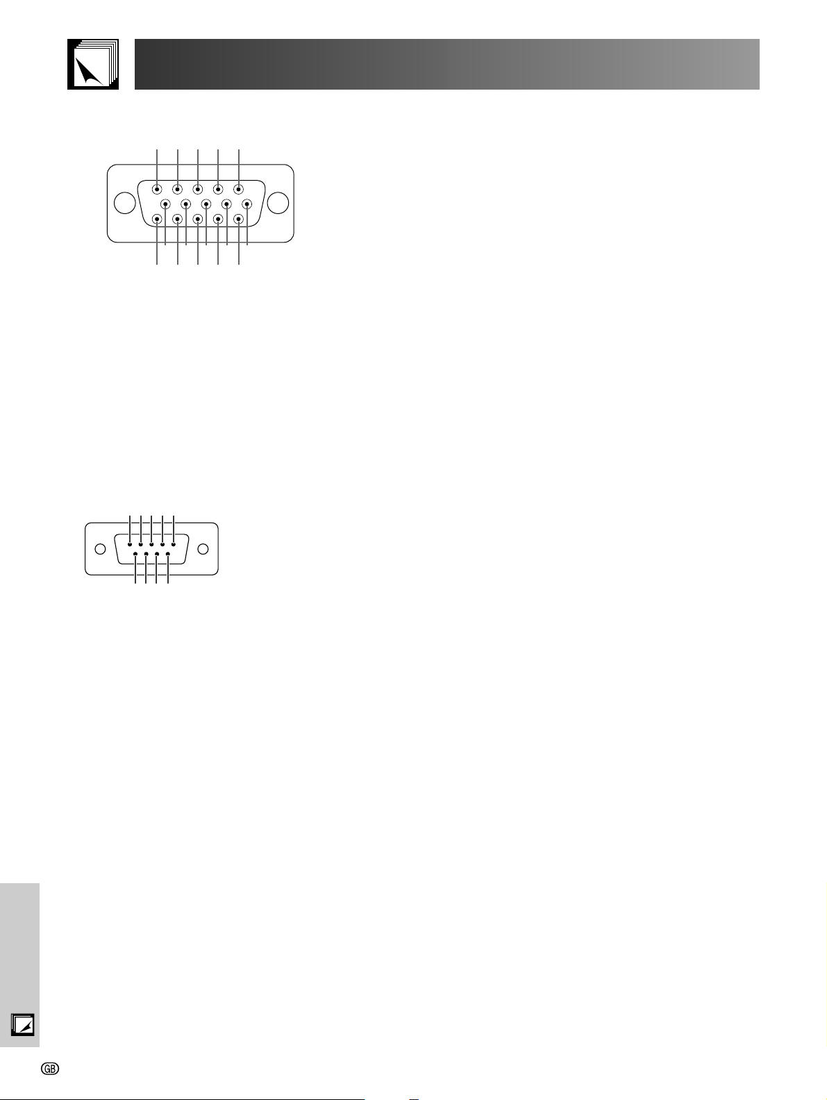
INPUT 2 COMPONENT/RGB Port: 15-pin Mini D-sub female connector
5 4 3 2 1
10 9 8 7 6
15 14 13 12 11
• RGB Input
Pin No. Signal
1 Video input (red)
2 Video input
(green/sync on green)
3 Video input (blue)
4 Not connected
5 Composite sync
6 Ground (red)
7 Ground (green/sync on green)
• Component Input
Pin No. Signal
1 Video input P
R (CR)
2 Video input Y
3 Video input P
B (CB)
4 Not connected
5 Not connected
6 Ground (P
R)
7 Ground (Y)
Pin No. Signal
8 Ground (blue)
9 Not connected
10 Ground
11 Ground
12 Bi-directional data
13 Horizontal sync signal
14 Vertical sync signal
15 Data clock
Pin No. Signal
8 Ground (P
B)
9 Not connected
10 Not connected
11 Not connected
12 Not connected
13 Not connected
14 Not connected
15 Not connected
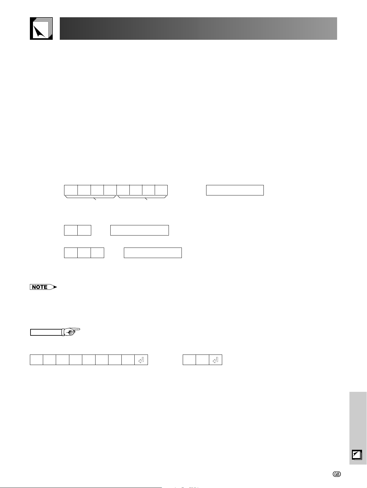
RS-232C Port: 9-pin D-sub male connector of the DIN-D-sub RS-232C cable
Pin No. Signal Name I/O Reference
1
2 3 4 5
6 7 8 9
1 Not connected
2 RD Receive Data Input Connected to internal circuit
3 SD Send Data Output Connected to internal circuit
4 Reserved Connected to internal circuit
5 SG Signal Ground Connected to internal circuit
6 Reserved Connected to internal circuit
7 Reserved Connected to internal circuit
8 Reserved Connected to internal circuit
9 Not connected
Appendix
-51
(RS-232C) Specifications and Command Settings
PC control
A computer can be used to control the projector by connecting an RS-232C cable (null modem, cross type,
commercially available) to the projector. (See page 14 for connection.)
Communication conditions
Set the serial port settings of the computer to match those of the table on the next page.
Signal format: Conforms to RS-232C standard.
Baud rate: 9,600 bps
Data length: 8 bits
Parity bit: NONE
Stop bit: 1 bit
Flow control: None
Basic format
Commands from the computer are sent in the following order: command, parameter, and return code. After the
projector processes the command from the computer, it sends a response code to the computer.
Command format
Return code (0DH)C1 C2 C3 C4 P1 P2 P3 P4
Command 4-digits Parameter 4-digits
Response code format
Normal response
O K
Problem response (communication error or incorrect command)
E R R
When more than one code is being sent, send each command only after the OK response code for the previous
command from the projector is verified.
• When using the computer control function of the projector, the projector operating status cannot be read to the computer.
Therefore, confirm the status by transmitting the display commands for each adjustment menu and checking the status with
the On-screen Display.
Return code (0DH)
Return code (0DH)
Commands
EXAMPLE
• When power on.
ProjectorComputer
POWR 1_ OK
__
→
←
Appendix
-52
(RS-232C) Specifications and Command Settings
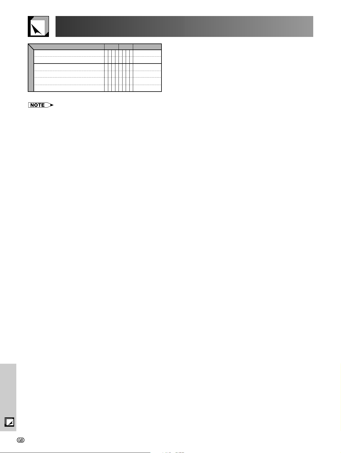
CONTROL CONTENTS
POWER ON
POWER OFF
INPUT 1 (COMPONENT 1)
INPUT 2 (COMPONENT 2)
INPUT 3 (S-VIDEO)
INPUT 4 (VIDEO)
BUTTONS & REMOTE CONTROL BUTTONS
COMMAND
W
O
P
W
O
P
E
V
I
E
V
I
E
V
I
E
V
I
PARAMETER
_
R
_
R
_
D
_
D
_
D
_
D
RETURN
1
_
_
OK OR ERR
0
_
_
OK OR ERR
1
_
_
OK OR ERR
2
_
_
OK OR ERR
3
_
_
OK OR ERR
4
_
_
OK OR ERR
• If an underbar (_) appears in the parameter column, enter a space.
Appendix
-53
 Loading...