

Page 1
XV-Z9000U/E
SERVICE MANUAL
SERVICE-ANLEITUNG
S81Y7XVZ9000U
DLP PROJECTOR
DLP PROJEKTOR
MODELS
MODELLE XV-Z9000U/E
In the interests of user-safety (Required by safety regulations in some countries) the set should be restored
to its original condition and only parts identical to those specified should be used.
Im lnteresse der Benutzersicherheit (erforderliche Sicherheitsregeln in einigen Ländern) muß das Gerät in seinen
Originalzustand gebracht werden. Außerdem dürfen für die spezifizierten Bauteile nur identische Teile verwendet
werden.
SHARP CORPORATION
This document has been published to be used for
after sales service only.
The contents are subject to change without notice.
1
Page 2

XV-Z9000U/E
• SPECIFICATIONS ............................................. 3
• INPOTANT SERVICE SAFETY NOTES ............ 4
• OPERATION MANUAL ...................................... 8
• REMOVING OF MAJOR PARTS ..................... 14
• RESETTING THE TOT AL LAMP TIMER ......... 20
• THE OPTICAL UNIT OUTLINE........................ 21
• ELECTRICAL ADJUSTMENT.......................... 24
• TROUBLE SHOOTING TABLE........................ 32
• CHASSIS LAYOUT .......................................... 92
• BLOCK DIAGRAM ........................................... 94
• OVERALL WIRING DIAGRAM ........................ 96
• DESCRIPTION OF SCHEMATIC DIAGRAM... 98
• WAVEFORMS.................................................. 99
CONTENTS
Page Page
• SCHEMATIC DIAGRAM ................................ 100
• PRINTED WIRING BOARD ASSEMBLIES ... 133
• P ARTS LIST
Ë
ELECTRICAL PARTS............................... 140
Ë
CABINET AND MECHANICAL PARTS .... 154
Ë
ACCESSORIES PARTS........................... 158
Ë
P ACKING PARTS ..................................... 158
• PACKING OF THE SET ................................. 159
Seite Seite
• TECHNISCHE DATEN..................................... 49
• HINWEISE FÜR DAS
WARTUNGSPERSONAL................................. 50
• BEDIENUNGSANLEITUNG............................. 51
• ENTFERNEN DER HAUPTTEILE ................... 57
• RÜCKSTELLEN DES
LAMPENBETRIEBSZEIT-TIMERS.................. 63
• BESCHREIBUNG DER OPTIK-EINHEIT ........ 64
• ELEKTRISCHE EINSTELLUNG ...................... 67
• FEHLERSUCHTABELLE ................................. 75
• CHASSIS-ANORDNUNG ................................ 92
• BLOCKSCHALTBILD ....................................... 94
• GESAMTSCHALTPLAN................................... 96
INHALT
• BESCHREIBUNG DES SCHEMATISCHEN
• WELLENFORMEN........................................... 99
• SCHEMATISCHER SCHALTPLAN................ 100
• LEITERPLATTENEINHEITEN ....................... 133
• ERSATZTEILLISTE
• VERPACKEN DES GERÄTS ......................... 159
SCHALTPLANS ............................................... 98
Ë
ELEKTRISCHE BAUTEILE ...................... 140
Ë
CEHÄUSE UND MECHANISCHE
BAUTEILE ................................................ 154
Ë
ZUBEHÖRTEILE...................................... 158
Ë
VERPACKUNGSTEILE ............................ 158
2
Page 3

Specifications
Product type DLP Projector
Video system
Computer VGA/SVGA/XGA/SXGA
Display method Single panel Digital Micromirror Device™(DMD™) by Texas Instraments
DMD panel Panel size:0.8" (20.3mm)
Projection lamp 250 W NSH lamp
Contrast ratio 1000:1
Video input signal RCA Connector:VIDEO,composite video,1.0 Vp-p,sync negative,75 Ω terminated (INPUT 4)
S-video input signal 4-pin Mini DIN connector (INPUT 3)
Component input signal RCA connector (INPUT 1 and 2 terminals)
Horizontal resolution 720 TV lines (DTV 720P input)
DC output 12V. MAX CURRENT 200mA CENTER + TYPE
Computer RGB input signal 15-PIN MINI D-SUB CONNECTOR (INPUT 5 port):
Wired Remote Control 3.5 ø Mini jack
Pixel clock 12 – 120MHz
Vertical frequency 43 – 100Hz
Horizontal frequency 15 – 80 kHz
Computer control signal 9-pin D-Sub male connector (RS-232C port)
Rated voltage AC 100 – 240 V
Input current 3.6 A
Rated frequency 50/60 Hz
Power consumption 345 W (Selecting "BRIGHT" in the "Theater Mode".)
Operating temperature+ 5 °C to + 35 °C (41 °F to + 95 °F )
Storage temperature− 20 °C to + 60 °C (− 4 °F to + 140 °F)
Cabinet Plastic
I/R carrier frequency 38 kHz
Dimensions (approx.) 18 11⁄16" (W) X 7" (H) X 15 15⁄50" (D)(475 X 178 X 406mm)(main body only)
Weight (approx.) 20.9 lbs.(9.5 kg)
Supplied accessories Remote control, Two AA size batteries, Power cord (1 1' 10" ,3.6 m(XV-Z9000U), 1.8m(XV -Z9000E)),
Replacement parts Lamp unit (Lamp/cage module) (BQC-XVZ9000/1), Remote control (RRMCG1657CESA), AA size
XV-Z9000U/E
Model XV-Z9000U/E
PAL/PAL 60/PAL- M/PAL- N/SECAM/NTSC 3.58/NTSC 4.43/DTV 480I/DTV 480P/DTV 720P/DTV 1080I
No.of dots:921,600 dots (1280 [H ] X 720 [V ])
Lens 1 – 1.35X zoom lens, F3, f = 32.5 – 44.0 mm
Y (luminance signal):1.0 Vp-p,sync negative,75 Ω terminated
C (chrominance signal):Burst 0.286 Vp-p,75 Ω terminated
Y:1Vp-p, sync negative, 75 Ω terminated
PB/PR:0.7Vp-p, 75 Ω terminated (XV-Z9000U)
CB/CR:0.7Vp-p, 75 Ω terminated (XV-Z9000E)
RGB separate/composite sync/sync on green type analog input:0 – 0.7 Vp-p,positive,
75 Ω terminated
HORIZONTAL SYNC.SIGNAL:TTL level (positive/negative)or composite sync (Apple only)
VERTICAL SYNC.SIGNAL:Same as above
18 11⁄16" (W) X 8" (H) X 19 1⁄2" (D)(475 X 203 X 496 mm)(including terminal cover and
adjustment feet)
Lens cap (attached), DLP projector operation manual, CD-ROM, CD-ROM operation manual,
Terminal cover, Video cable(XV-Z9000E), VGA cable(XV-Z9000E), 21pin-RCA adaptor(XVZ9000E), Guarrantee card for U.S., Guarrantee card for CANADA.
batteries, Power cord (CACCU5013DE01 (XV-Z9000U), QACCV4002CEZZ (XV-Z9000E),
QACCB5024CENA (XV -Z9000E)), Lens cap (PCAPH1056CESA),DLP projector operation manual
(TINS-7415CEZZ (XV-Z9000U), TINS-7521CEZZ (XV-Z9000E)), CD-ROM(UDSKA0047CEN1),
CD-ROM operation manual (TINS-7418CEZZ (XV-Z9000U), TINS-7523CEZZ (XV-Z9000E)), V ideo
cable(QCNWGA001WJZZ(XV-Z9000E)), VGA cable(QCNW-5050CEZZ(XV -Z9000E)), 21pin-RCA
adaptor(QSOCZ0361CEZZ(XV-Z9000E)), Guarrantee card for U.S.(TGAN-1670CEZZ),
Guarrantee card for CANADA (TGAN-1671CEZZ).
This SHARP projector uses a DMD panels.This very sophisticated
panels contain 921,600 pixels. As with any high technology electronic equipment such as large screen TVs,video systems and video
cameras, there are certain acceptable tolerances that the equipment must conform to.
Specifications are subject to change without notice.
This unit has some inactive pixels within acceptable tolerances which
may result in inactive dots on the picture screen.This will not affect
the picture quality or the life expectancy of the unit.
If you have any questions about this matter,please call toll free 1888-GO-SHARP (1-800-237-4277). U.S.A.ONLY
3
Page 4
XV-Z9000U/E
2
2
IMPORTANT SERVICE SAFETY NOTES (for USA)
Ë Service work should be performed only by qualified service technicians who are
thoroughly familiar with all safety checks and servicing guidelines as follows:
WARNING
1. For continued safety, no modification of any circuit
should be attempted.
2. Disconnect AC power before servicing.
BEFORE RETURNING THE PROJECTOR:
(Fire & Shock Hazard)
Before returning the projector to the user, perform
the following safety checks:
1. Inspect lead wires are not pinched between the
chassis and other metal parts of the projector.
2. Inspect all protective devices such as non-metallic
control knobs, insulating materials, cabinet backs,
adjustment and compartment covers or shields,
isolation resistor-capacity networks, mechanical
insulators, etc.
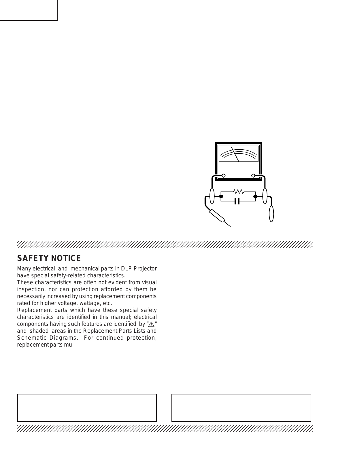
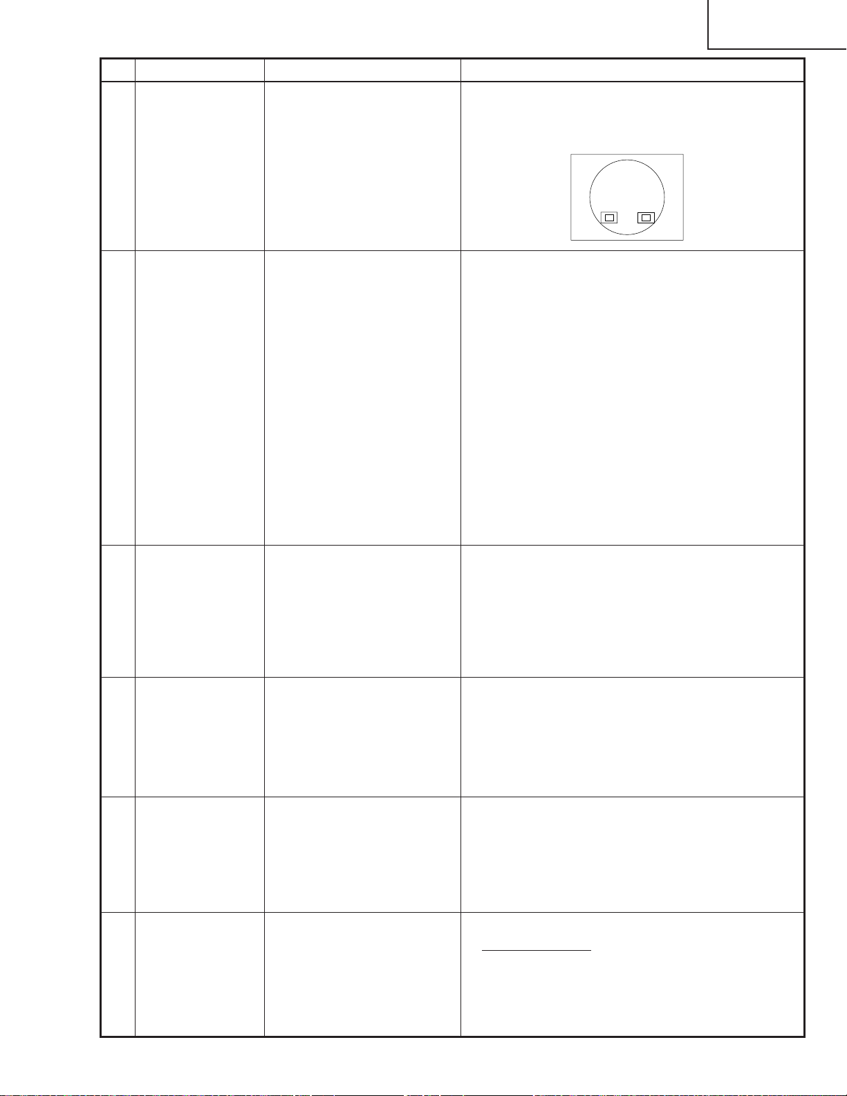
3. To be sure that no shock hazard exists, check for
current leakage in the following manner:
» Plug the AC cord directly into a 120-volt AC outlet,
(Do not use an isolation transformer for this test).
» Using two clip leads, connect a 1.5k ohm, 10 watt
resistor paralleled by a 0.15µF capacitor in parallel
between all exposed metal cabinet parts and earth
ground.
» Use an AC voltmeter with sensitivity of 5000 ohm per
volt., or higher, sensitivity to measure the AC voltage
drop across the resistor (See Diagram).
» All checks must be repeated with the AC plug
connection reversed. (If necessary , a non-polarized
adapter plug must be used only for the purpose of
completing these checks.)
Any reading of 0.3 volts RMS (this corresponds to
0.2 milliamp. AC.) or more is excessive and indicates
a potential shock hazard which must be corrected
before returning the unit to the owner.
AC
VOLTMETER
1.5k ohm (10W)
0.15µF
TEST PROBE
TO EXPOSED
METAL PARTS
CONNECT TO KNOWN
EARTH GROUND
234567890123456789012345678901212345678901234567890123456789012123456789012345678901234567890121
SAFETY NOTICE
Many electrical and mechanical parts in DLP Projector
have special safety-related characteristics.
These characteristics are often not evident from visual
inspection, nor can protection afforded by them be
necessarily increased by using replacement components
rated for higher voltage, wattage, etc.
Replacement parts which have these special safety
characteristics are identified in this manual; electrical
components having such features are identified by “å”
and shaded areas in the Replacement Parts Lists and
Schematic Diagrams. For continued protection,
replacement parts must be identical to those used in the
original circuit. The use of a substitute replacement parts
which do not have the same safety characteristics as
the factory recommended replacement parts shown in
this service manual, may create shock, fire or other
hazards.
AVIS POUR LA SECURITE
De nombreuses pièces, électriques et mécaniques, dans
les projecteur à DLP présentent des caractéristiques
spéciales relatives à la sécurité, qui ne sont souvent
pas évidentes à vue.
Le degré de protection ne peut pas être nécessairement
augmentée en utilisant des pièces de remplacement
étalonnées pour haute tension, puissance, etc.
Les pièces de remplacement qui présentent ces
caractéristiques sont identifiées dans ce manuel;
les pièces électriques qui présentent ces particularités
sont identifiées par la marque “å” et hachurées dans la
liste des pièces de remplacement et les diagrammes
schématiques. Pour assurer la protection, ces pièces
doivent être identiques à celles utilisées dans le circuit
d’origine. L’utilisation de pièces qui n’ont pas les mêmes
caractéristiques que les pièces recommandées par
l’usine, indiquées dans ce manuel, peut provoquer des
électrocutions, incendies ou autres accidents.
WARNING: The bimetallic component has the primary
conductive side exposed. Be very careful in
handling this component when the power is on.
234567890123456789012345678901212345678901234567890123456789012123456789012345678901234567890121
AVERTISSEMENT: La composante bimétallique dispose du
conducteur primaire dénudé. Faire
attention lors de la manipulation de cette
composante sous tension.
4
Page 5
XV-Z9000U/E
5
5
NOTE TO SERVICE
PERSONNEL
UV-RADIATION PRECAUTION
234567890123456789012345678901212345678901234
The light source, lamp, in the projector emits small
amounts of UV-Radiation.
A VOID DIRECT EYE AND SKIN EXPOSURE.
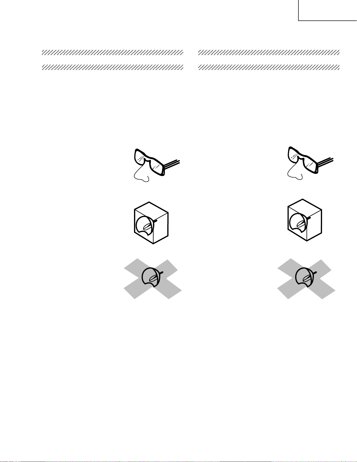
To ensure safety please adhere to the following:
1. Be sure to wear sun-glasses when servicing the
projector with the lamp
turned “on” and the top
enclosure removed.
2. Do not operate the lamp outside of the lamp housing.
NOTE POUR LE PERSONNEL
D’ENTRETIEN
PRECAUTION POUR LES RADIATIONS UV
234567890123456789012345678901212345678901234
La source de lumière, la lampe , dans le projecteur
émet de petites quantités de radiation UV.
EVITEZ TOUTE EXPOSITION DIRECTE
DES YEUX ET DE LA PEAU.
Pour votre sécurité, nous vous prions de respecter
les points suivants:
1. Toujours porter des lunettes de soleil lors d’un
entretien du projecteur
avec la lampe allumée
et le haut du coffret retiré.
2. Ne pas faire fonctionner la lampe à l’extérieur du
boîtier de lampe.
3. Do not operate for more than 2 hours with the
enclosure removed.
UV-Radiation and Medium Pressure
Lamp Precautions
1. Be sure to disconnect the AC plug when replacing
the lamp.
2. Allow one hour for the unit to cool down before
servicing.
3. Replace only with same type lamp. Type BQCXVZ9000/1 rated 355V/250W.
4. The lamp emits small amounts of UV-Radiation, avoid
direct-eye contact.
5. The medium pressure lamp involves a risk of
explosion. Be sure to follow installation instructions
described below and handle the lamp with care.
3. Ne pas faire fonctionner plus de 2 heures avec le
coffret retiré.
Précautions pour les radiations UV
et la lampe moyenne pression
1. Toujours débrancher la fiche AC lors du
remplacement de la lampe.
2. Laisser l’unité refroidir pendant une heure avant de
procéder à l’entretien.
3. Ne remplacer qu’avec une lampe du même type.
Type BQC-XVZ9000/1, caractéristique 355V/250W.
4. La lampe émet de petites quantités de radiation UVéviter tout contact direct avec les yeux.
5. La lampe moyenne pression implique un risque
d’explosion. Toujours suivre les instructions
d’installation décrites ci-dessous et manipuler la
lampe avec soin.
5
Page 6
XV-Z9000U/E
5
4
5
5
234567890123456789012345678901212345678901234
UV-RADIATION PRECAUTION (Continued)
23456789012345678901234567890121234567890123
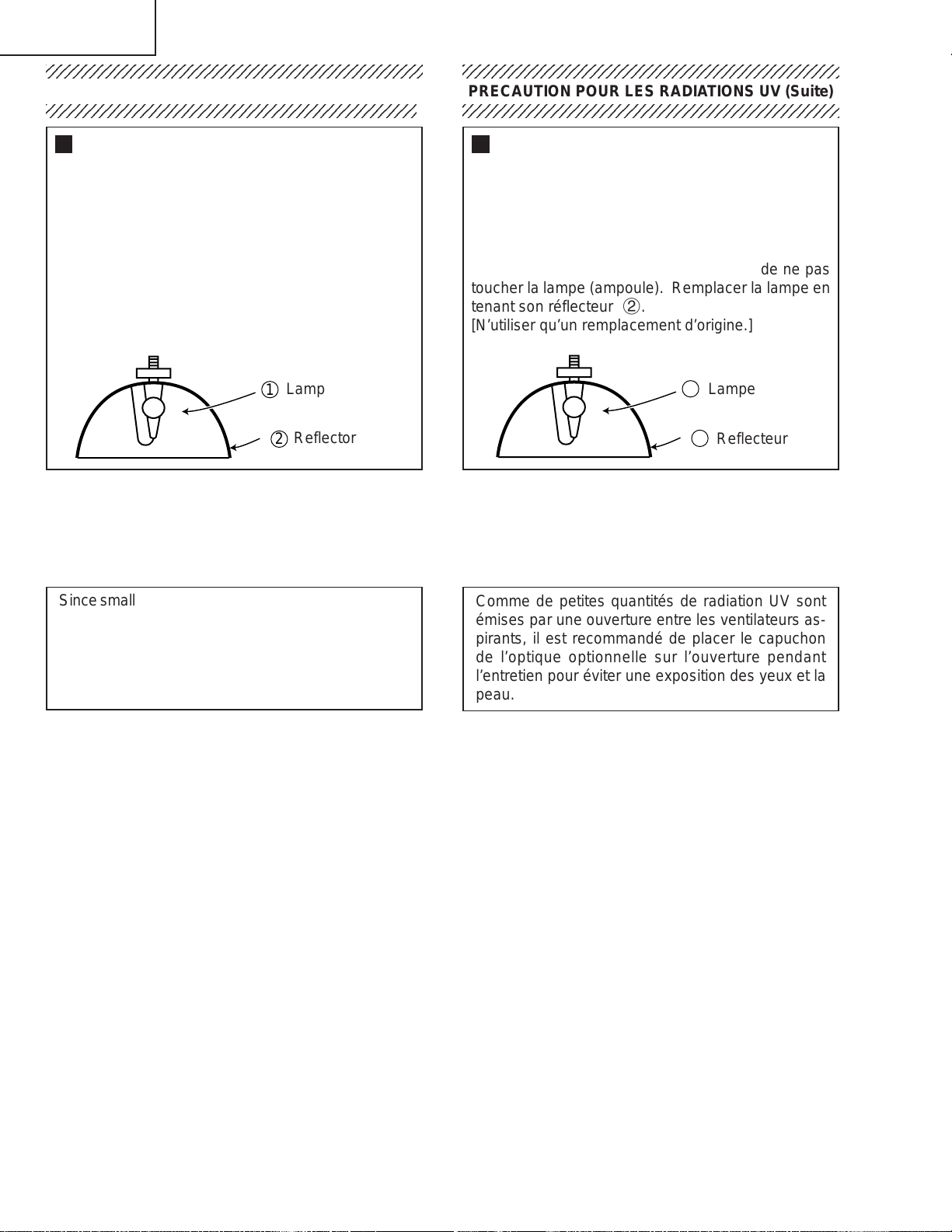
Lamp Replacement
Note:
Since the lamp reaches a very high temperature
during units operation replacement of the lamp
should be done at least one hour after the power
has been turned off. (to allow the lamp to cool off.)
Installing the new lamp, make sure not to touch the
lamp (bulb) replace the lamp by holding its reflector
2.
[Use original replacement only.]
Lamp
1
Reflector
2
DANGER ! –– Never turn the power on without the
lamp to avoid electric-shock or damage of the
devices since the stabilizer generates high voltages
at its start.
234567890123456789012345678901212345678901234
PRECAUTION POUR LES RADIATIONS UV (Suite)
234567890123456789012345678901212345678901234
Remplacement de la lampe
Remarque:
Comme la lampe devient très chaude pendant le
fonctionnement de l’unité, son remplacement ne doit
être effectué au moins une heure après avoir coupé
l’alimentation (pour permettre à la lampe de refroidir).
En installant la nouvelle lampe, s’assurer de ne pas
toucher la lampe (ampoule). Remplacer la lampe en
tenant son réflecteur 2.
[N’utiliser qu’un remplacement d’origine.]
1
Lampe
2
Reflecteur
DANGER ! –– Ne jamais mettre sous tension sans
la lampe pour éviter un choc électrique ou des
dommages des appareils car le stabilisateur génère
de hautes tensions à sa mise en route.
Since small amounts of UV-radiation are emitted from
an opening between the exhaust fans, it is recommended to place the cap of the optional lens on the
opening during servicing to avoid eye and skin exposure.
Comme de petites quantités de radiation UV sont
émises par une ouverture entre les ventilateurs aspirants, il est recommandé de placer le capuchon
de l’optique optionnelle sur l’ouverture pendant
l’entretien pour éviter une exposition des yeux et la
peau.
6
Page 7
XV-Z9000U/E
12345678901234567890123456789012123456789012345678901234567890121234567890123456789012345678901212
12345678901234567890123456789012123456789012345678901234567890121234567890123456789012345678901212
WARNING: High brightness light source, do not stare into the beam of light, or view directly . Be especially
careful that children do not stare directly in to the beam of light.
WARNING: TO REDUCE THE RISK OF FIRE OR ELECTRIC SHOCK, DO NOT EXPOSE THIS UNIT TO
MOISTURE OR WET LOCATIONS.
CAUTION
RISK OF ELECTRIC SHOCK.
DO NOT REMOVE SCREWS
EXCEPT SPECIFIED USER
SERVICE SCREW
CAUTION: TO REDUCE THE RISK OF ELECTRIC SHOCK,
DO NOT REMOVE CABINET.
NO USER-SERVICEABLE P ARTS EXCEPT LAMP UNIT.
REFER SERVICING TO QUALIFIED SERVICE
PERSONNEL.
The lighting flash with arrowhead within a
triangle is intended to tell the user that
parts inside the product are risk of electric
shock to persons.
The exclamation point within a triangle is
intended to tell the user that important
operating and servicing instructions are in
the manual with the projector.
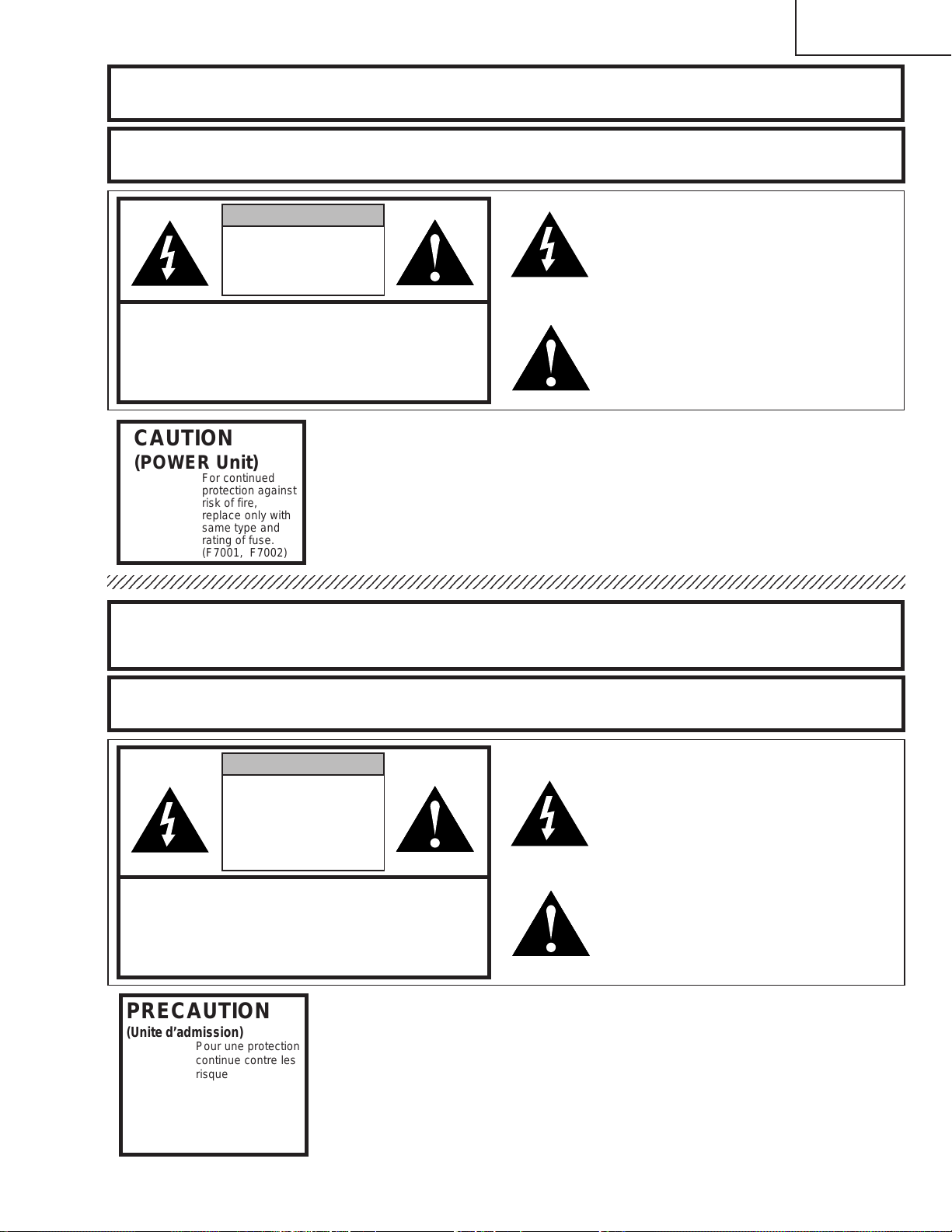
CAUTION
(POWER Unit)
A VERTISSEMENT : Source lumineuse de grande intensité. Ne pas fixer le faisceau lumineux ou le regarder
For continued
protection against
risk of fire,
replace only with
same type and
rating of fuse.
(F7001, F7002)
directement. Veiller particulièrement à éviter que les enfants ne fixent directement le
faisceau lumineux.
A VERTISSEMENT : AFIN D’EVITER TOUT RISQUE D’INCENDIE OU D’ELECTROCUTION, NE P AS PLACER
CET APPAREIL DANS UN ENDROIT HUMIDE OU MOUILLE.
ATTENTION
RISQUE
D’ELECTROCUTION NE
PASRETIRER LES VIS, A
L’EXCEPTION DES VIS DE
REPARATION UTILISATEUR
SPECIFIEES
L’éclair terminé d’une flèche à l’intérieur
d’un triangle indique à l’utilisateur que les
pi‘eces se trouvant dans l’appareil sont
susceptibles de provoquer une décharge
électrique.
Le point d’exclamation à l’intérieur d’un
ATTENTION: POUR EVITER TOUT RISQUE
D’ELECTROCUTION, NE PAS RETIRER LE CAPOT.
AUCUNE DES PIECES INTERIEURES N’EST REP ARABLE
PAR L’UTILISA TEUR, A L’EXCEPTION DE L’UNITE DE
LAMPE. POUR TOUTE REP ARATION, S’ADRESSER A UN
TECHNICIEN D’ENTRETIEN QUALIFIE.
triangle indique à l’utilisateur que les
instructions de fonctionnement et
d’entretien sont détaillées dans les
documents fournis avec le projecteur.
PRECAUTION
(Unite d’admission)
Pour une protection
continue contre les
risques d’incendie,
ne remplacer
qu’avec un fusible
du même type.
(F7001, F7002)
7
Page 8

XV-Z9000U/E
r
Location of Controls
Projector
Front and Top View
Lens shift dial
Remote control sensor
Zoom knob
Focus ring
Adjuster
ENTER button
UNDO button
Lens cap
ADJUSTMENT buttons
('/"/\/|)
Remote control sensor
MENU button
RESIZE button
TEMPERATURE WARNING indicato
LAMP REPLACEMENT indicator
POWER indicator
Intake ventilative hole
Adjuster
INPUT button
POWER buttons
(ON/OFF)
Side and Rear View
8
Page 9
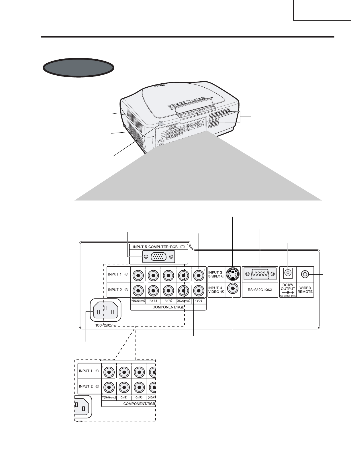
Projector
Side and Rear Vie
w
AC socket
Intake ventilative hole 4
DC 12 V OUTPUT terminal
(200 mA MAX.)
INPUT 5 COMPUTER-RGB port
RGB terminals (RCA)
INPUT 2 COMPONENT/
RGB terminals (RCA)
Wired remote
control jack
VIDEO INPUT 4 terminal (RCA)
S-VIDEO INPUT 3 terminal
(4-pin Mini DIN)
RS-232C port
(9-pin D-sub)
Intake ventilative hole
Exhaust ventilative hole
Remote control sensor
INPUT 1 COMPONENT/
(15-pin Mini D-sub)
XV-Z9000U
XV-Z9000E
XV-Z9000U/E
9
Page 10
XV-Z9000U/E
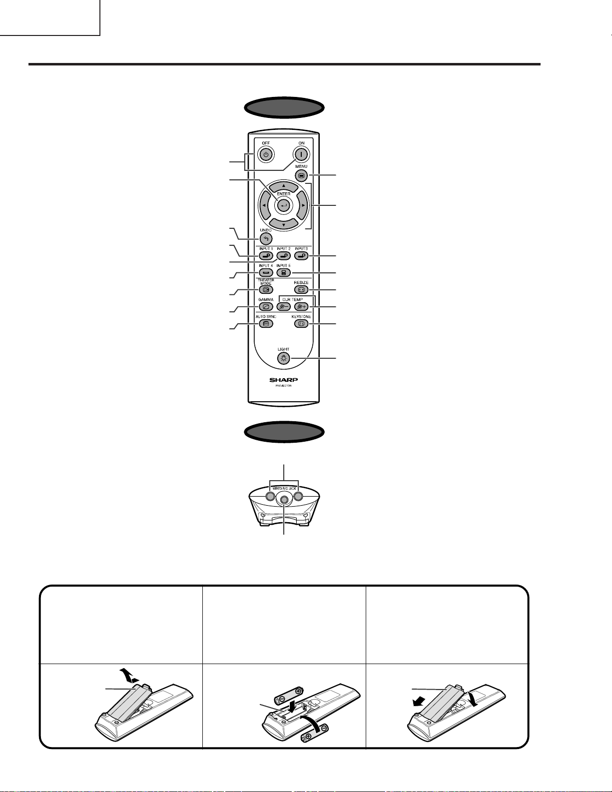
Remote Control
POWER buttons (ON/OFF)
ENTER button
UNDO button
INPUT 1 button
INPUT 2 button
INPUT 4 button
THEATER MODE button
GAMMA button
AUTO SYNC button
Front View
MENU button
ADJUSTMENT buttons
(\/|/'/")
INPUT 3 button
INPUT 5 button
RESIZE button
CLR TEMP buttons
KEYSTONE button
Inserting the batteries
Pull down the tab on the
1
battery cover and
remove the cover
towards the direction of
the arr o w.
T op View
Remote control signal transmitter
Wired remote control jack
Insert tw o AA size
2
batteries, making sure
the polarities match the
+ and – marks inside
the battery compartment.
BACKLIGHT button
Insert the lower tab of
3
the battery cover into
the opening, and press
the cover until it clicks
in place.
Battery cover
Battery
Battery
compartment
10
Page 11
a
Remote Control
d
l
e
XV-Z9000U/E
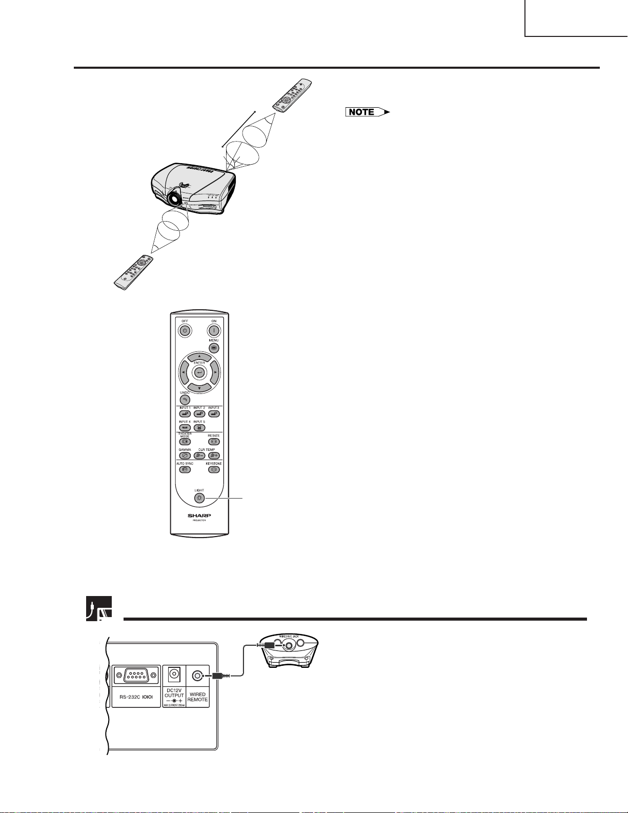
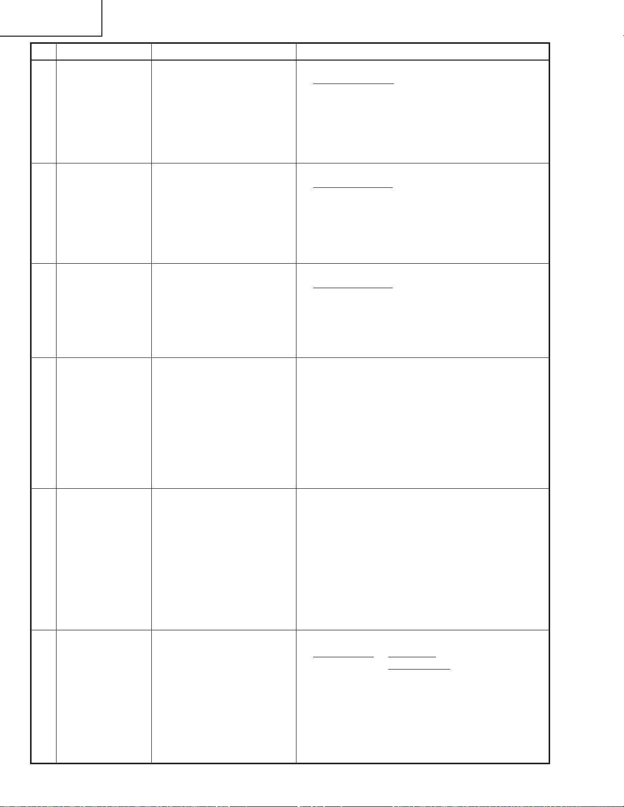
The remote control can be used to control the projector within the range shown on the left.
45˚
30˚
Remote Control
23 (7 m)
45˚
30˚
30˚
• The signal from the remote control can be r eflected of f
screen for easy operation. However, the effective distance
of the signal may differ due to the scr een material.
Using the remote control in a dark
room
The backlights of the operation buttons can be tur ne
on for five seconds and off by pressing BACKLIGHT.
If you want to turn off the backlights while they ar
press BACKLIGHT again.
BACKLIGHT button
Using as a Wired Remote Control
When the remote control cannot be used due to the
range or positioning of the projector (r ear projection,
etc.), connect a 3.5 mm stereo minijack cable
(commercially available) from the wired remote contro
3.5 mm stereo minijack cable
(commercially available)
jack on the top of the remote control to the Wired remot
control jack on the back of the projector.
11
Page 12
XV-Z9000U/E
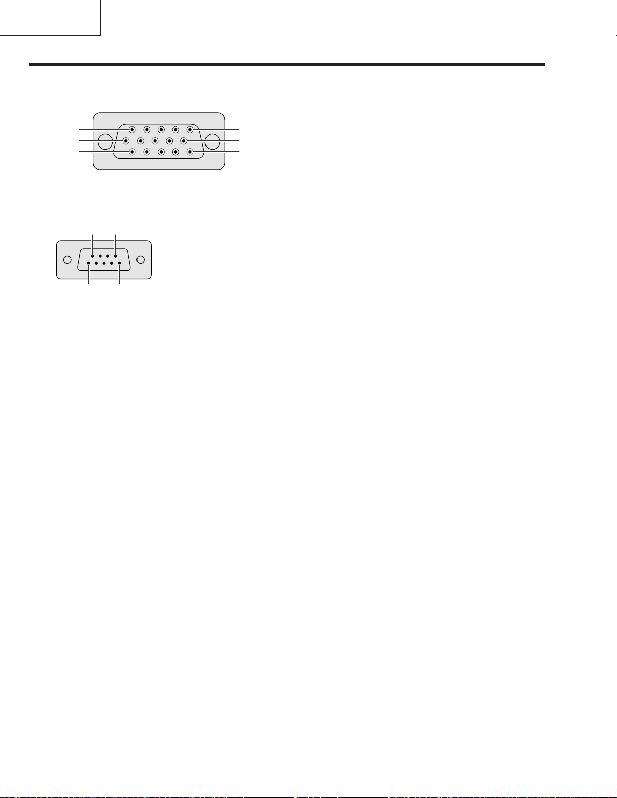
Connection Pin Assignments
INPUT 5 RGB Signal Input Port: 15-pin Mini D-sub female connector
RGB Input
Analog
1. Video input (red)
11
6
1
15
10
5
RS-232C Port: 9-pin D-sub male connector of the DIN-D-sub RS-232C cable
356
1
Pin No. Signal Name I/O Reference
1 Not connected
2 RD Receive Data Input Connected to internal circuit
3 SD Send Data Output Connected to internal circuit
4 Reserved Connected to internal circuit
5 SG Signal Ground Connected to internal circuit
6 Reserved Connected to internal circuit
7 Reserved Connected to internal circuit
8 Reserved Connected to internal circuit
9 Not connected
2. Video input
(green/sync on green)
3. Video input (blue)
4. Not connected
5. Composite sync
6. Earth (red)
7. Earth (green/sync on green)
8. Earth (blue)
9. Not connected
10. GND
11. GND
12. Bi-directional data
13. Horizontal sync signal
14. Vertical sync signal
15. Data clock
12
Page 13
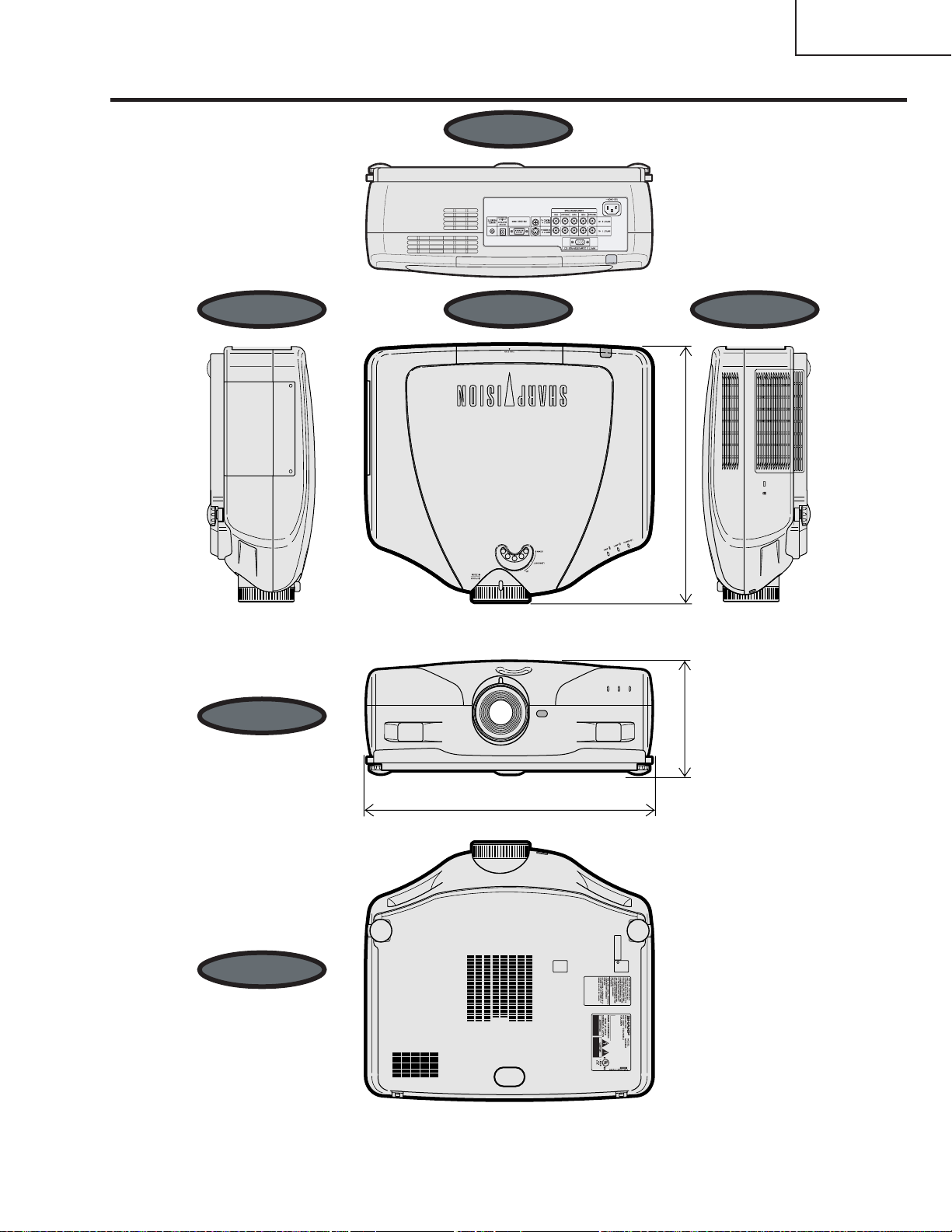
Dimensions
Side View Top View Side View
Rear View
(406)
50
/
49
15
XV-Z9000U/E
Front View
Bottom View
18
11
/16 (475)
7 (178)
Unit: inches (mm)
13
Page 14

XV-Z9000U/E
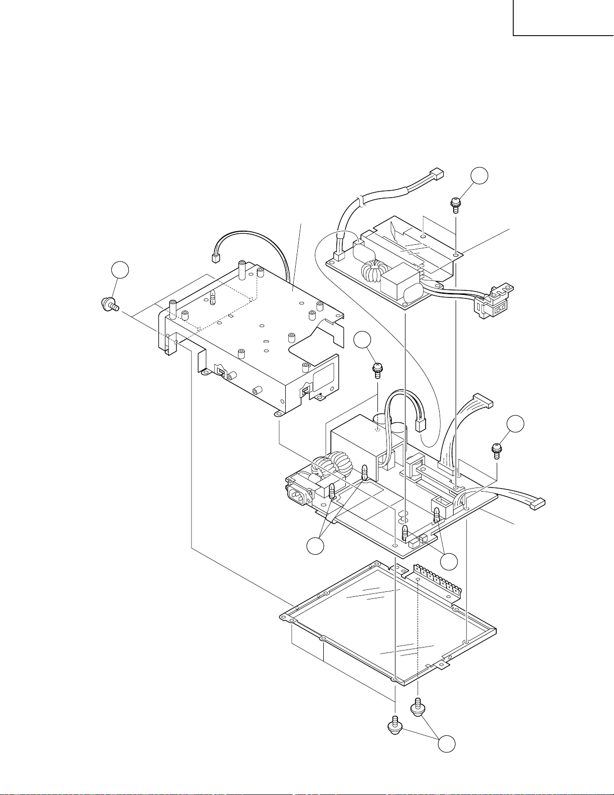
REMOVING OF MAJOR PARTS
1.Removing the top panels
1-1. Remove the six lock screw.
1-2. Press on side Arrow A of the bottom body
and Lift the rear body.
1-3. Disconnect the connector.
1-4. Press on front Arrow B of the bottom
body and unhook the claws, and detach
the top body.
2-1. Remove the two screws and detach the LED PWB.
2-2. Remove the one screw and detach the R/C PWB.
2-3. Remove the three screws and detach the operation PWB.
2-1
2-2
LED PWB
R/C PWB
2-3
Operation PWB
Top body
1-1
1-4
1-4
1-1
1-3
1-1
1-4
B
1-4
B
1-2
A
A
1-1
14
Page 15
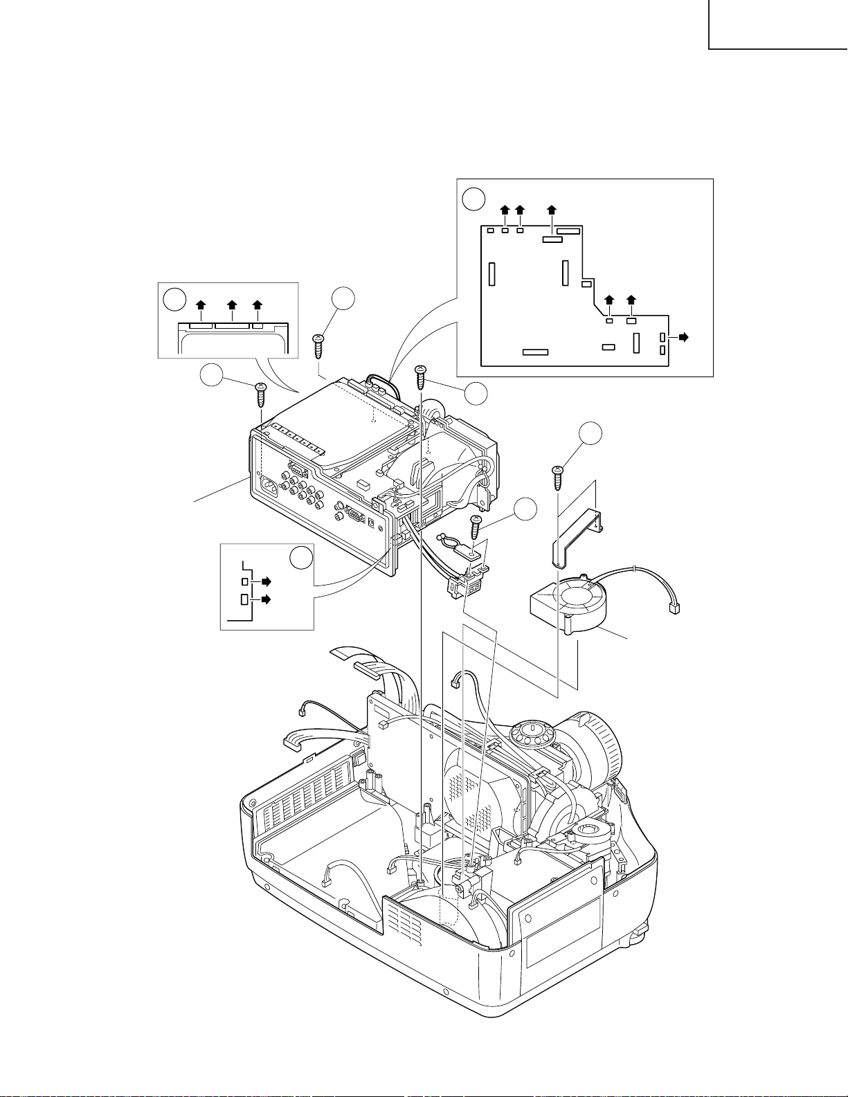
2.Removing the cooling fan and PWB unit assembly.
3-1. Disconnect the eleven connectors.
3-2. Remove the two screws and detach the lamp socket.
3-3. Remove the two screws and detach the cooling fan.
3-4. Remove the four screws and detach the PWB unit assembly.
(RC)(TA) (J2)
3-1
XV-Z9000U/E
(J5) (J3) (DB1)
3-1
3-4
PWB unit assembly
LAMP
3-1
Door SW
Bi-Metal
3-4
(FD) (FB)
(FA)
3-4
3-3
3-2
Cooling Fan
15
Page 16
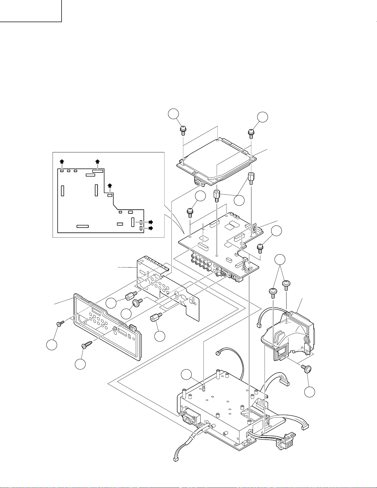
XV-Z9000U/E
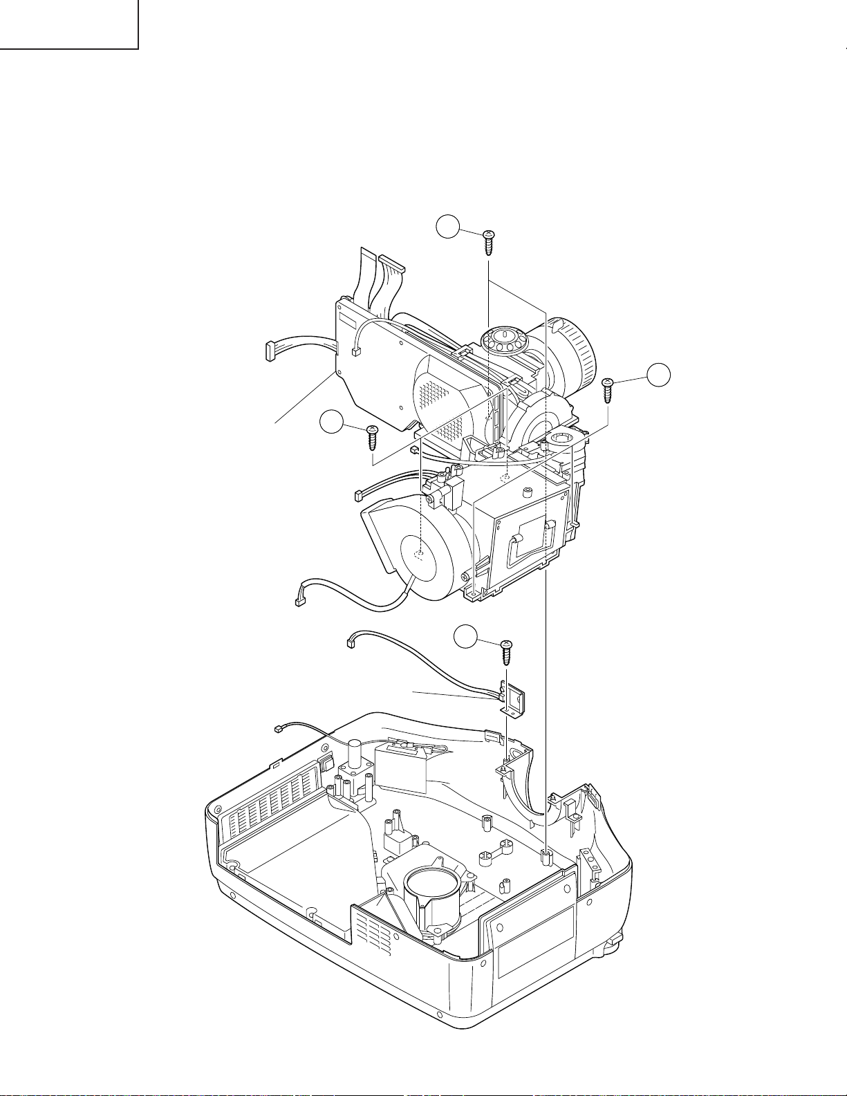
3.Removing the rear panel, PC unit, cooling duct and main PWB unit.
4-1. Remove the two screws.
4-2. Remove the three screws and detach the rear panel.
5-1. Remove the two screws.
5-2. Remove the four hexagonal supports and detach the shield plate.
6-1. Remove the four screws and detach the PC I/F unit.
7-1. Remove the four screws and detach the cooling duct.
8-1. Remove the two hexagonal supports.
8-2. Remove the five screws and detach the main PWB unit.
8-3. Remove the lock of the holder.
(TB) (EA)
Shield plate
(FC)
(EB)
(CA)
6-1
8-2
6-1
PC I/F unit
8-1
Main PWB unit
8-2
7-1
Rear panel
4-1
Cooling duct
5-2
5-1
5-2
4-2
8-3
7-1
16
Page 17
4.Removing the power unit shield , power/ballast unit and power unit.
9. Remove the seven screws and detach the power unit shield.
10-1. Remove the two screws.
10-2. Remove the four white supports and detach the power unit.
11. Remove the four screws and detach the power unit.
10-1
XV-Z9000U/E
Power unit shield
9
11
Ballast unit
11
10-2
Power unit
10-2
9
17
Page 18
XV-Z9000U/E
5.Removing the optical mechanism unit and R/C PWB unit.
12. Remove the six screws and detach the optical mechanism unit.
13. Remove the one screw and detach the R/C PWB unit.
12
12
Optical mechanism unit
12
13
R/C PWB unit
18
Page 19
XV-Z9000U/E
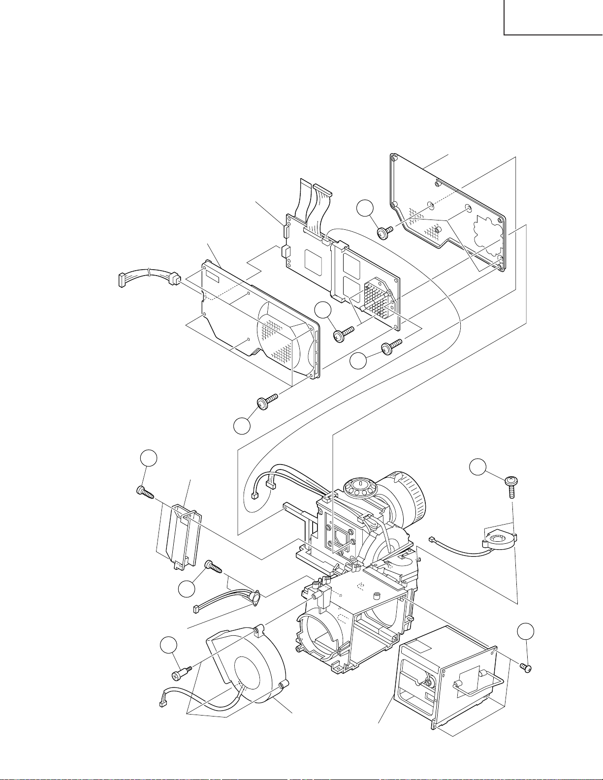
6.Removing the lamp unit, CW fan, outlet fan, bimetal, wind way duct, shield
plate and formater PWB.
14. Remove the three screws and detach the lamp unit.
15. Remove the two screws and detach the CW fan.
16. Remove the three screws and detach the outlet fan.
17-1. Remove the two screws and detach the bimetal.
17-2. Remove the two screws and detach wind way duct.
18-1. Remove the six screws and detach the shield plate(B).
18-2. Remove the three screws and detach the formater PWB.
18-3. Remove the three screws and detach the shield plate(A).
Formater PWB
18-3
Shield Plate(B)
Shield Plate(A)
17-2
Wind way Duct
18-2
18-2
18-1
15
17-1
Bimetal
16
14
Outlet Fan
Lamp unit
19
Page 20
XV-Z9000U/E
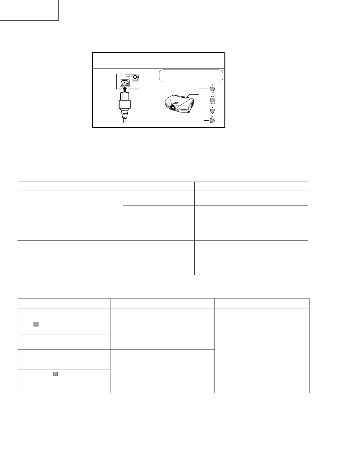
Resetting the TOTAL LAMP TIMER
● Resetting the total lamp timer
When replacing the lamp, reset the total lamp timer in the procedure below.
Plug in the power cord.
1
● Light source (lamp)
The lamp in this projector operates for approximately 2,000 cumulative hours, depending on the usage environment. (As the usage environment can vary significantly, the projector lamp may not operate for 2,000 hours.) It is
recommended that the lamp be replaced after approximately 1,900 cumulative hours of use or when you notice a
significant deterioration of the picture and color quality. The lamp usage time can be checked with the On-screen
Display.
Press POWER ON on
2
projector to reset lamp
timer.
While holding down ENTER, [
and >, press POWER ON.
Maintenance Indicator
TEMPERATURE
WARNING indicator
LAMP REPLACEMENT indicator
Condition
The LAMP REPLACEMENT
indicator lights up red, and “LAMP”
and “
” will flash in yellow in the
lower-left corner of the picture.
A significant deterioration of the
picture and color quality occurs.
The power will automatically turn
off and the projector will enter
stand-by mode.
“LAMP” and “
the lower-left corner of the picture,
and the power will turn off.
” will flash in red in
Condition Possible Solution
The internal
temperature is
abnormally high.
The lamp does not
light up.
The lamp requires
replacement.
Problem
• Blocked air intake.
• Clogged air filter.
• Cooling fan breakdown.
• Internal circuit failure.
• Burnt-out lamp.
• Lamp circuit failure.
• Lamp has been used for
over 1,900 hours.
Problem
• Lamp has been used for over 1,900
hours.
• Lamp has been used for over 2,000
hours.
• Relocate the projector to an area with
proper ventilation.
• Clean the filters.
• Take the projector to your nearest
Authorized SharpVision or Service Center
or Dealer for repair.
• Carefully replace the lamp.
• Take the projector to your nearest
Authorized Sharp Vision Service Center or
Dealer for repair.
Possible Solution
• Purchase a replacement lamp unit
(lamp/cage module) of the current
type BQC-XVZ9000/1 from your
nearest Authorized SharpVision
Service Center or Dealer.
• Replace the lamp. If you wish, you
may have the lamp replaced at your
nearest Authorized SharpVision
Service Center or Dealer.
20
Page 21
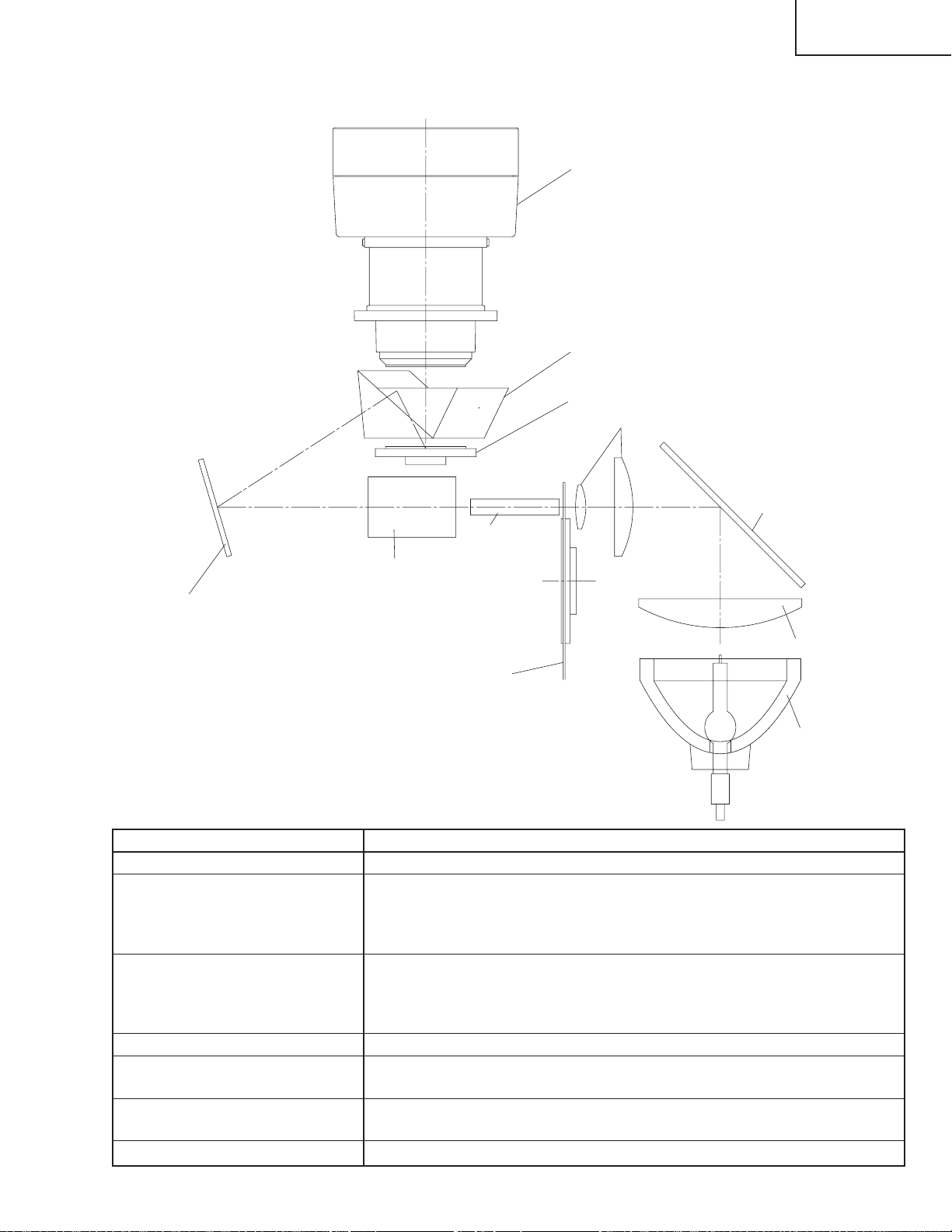
THE OPTICAL UNIT OUTLINE
Layout for proper setup of the optical components and parts (top view)
Projection lens
Prism
DMD Chips
Condensor lens
XV-Z9000U/E
Fold mirror
Item
1 Lamp
2 Condebsor lens, IR-cut mirror
and light- tunnel
3 Color filter
4 Relay lens and fold mirror
5 Prism
6 DMD chip
7 Projection lens
IR-cut mirror
Light tunnel
Relay lens
Condensor lens
Color filter
Lamp
Descriptions
The DC Light source lamp with parabola reflector.
The condensor lens leads the light generated from the lamp to the end sur-
face of the light-tunnel through the IR-cut mirror.
The IR-cut mirror is set in this unit to eliminate the excessive heat by the lamp
energy .
This color filter separates the white light into the 3 colors R,G and B.
A photo-sensor should be set in this unit to detect the transition timing pproperly
between color filters.
The maximum rrotating speed is 9000rpm.
This unit leads the illumination spot to effective area on DMD.
This prism also leads the illumination spot to effective area on DMD and at the
same time leads the reflection lights on the DMD to the projection lens.
This chip turns on and off in projection to each color component per dot de-
pending on the input source.
This lens enlarges and projects the incidend light coming from the DMD.
21
Page 22
XV-Z9000U/E
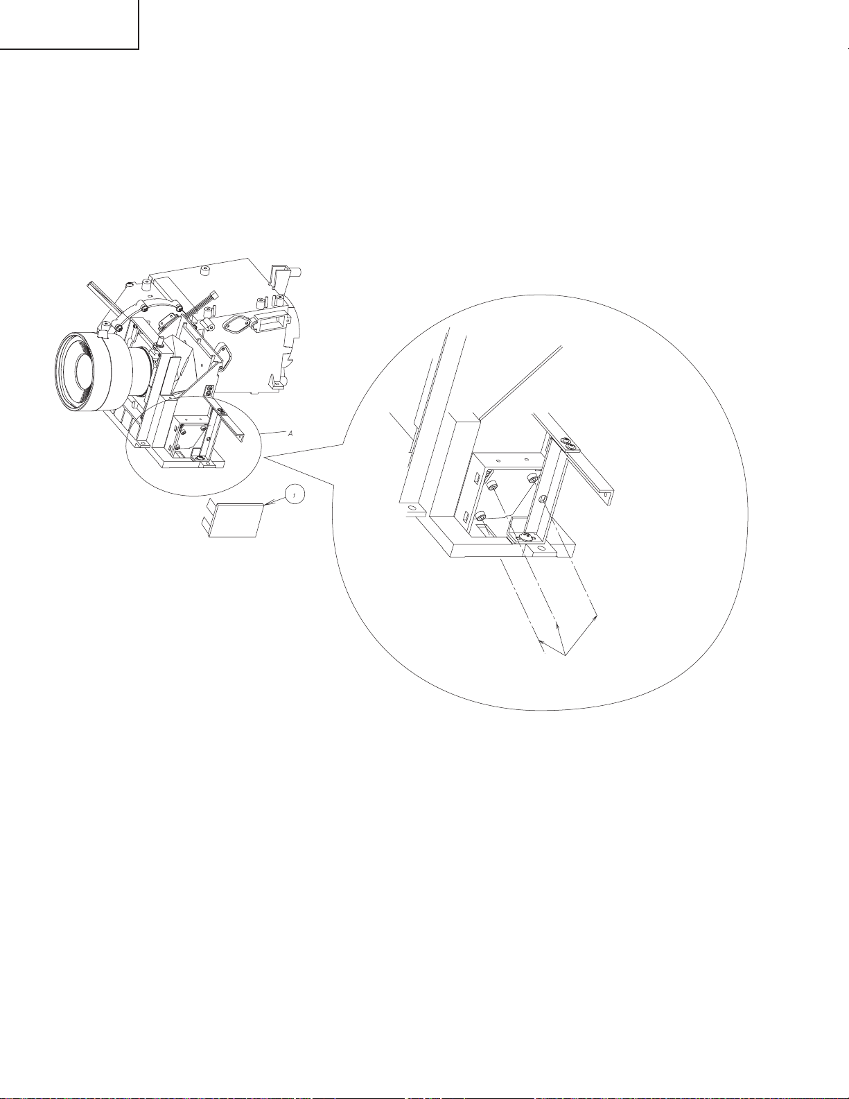
Adjusting the mirrors
Make adjustment by the indication territory on the screen to prevent the circumference of the screen from getting
dark because a lighting range deviated.
1. Remove the top body so that the optical unit may be seen. Display white only screen on the screen.
2. Detach the mirror adjustment part cover 1 on the bottom right of the projection lens.
3. T urn three screws with special hexagon wrench (9HPH10XL120) and adjust so that a part of the screen may not get
dark because a lighting range deviated.
4. Mount the adjustment part cover 1.
5. Mount the top panel.
Insert hexagon wrench
in this direction.
Expansion figure of part A
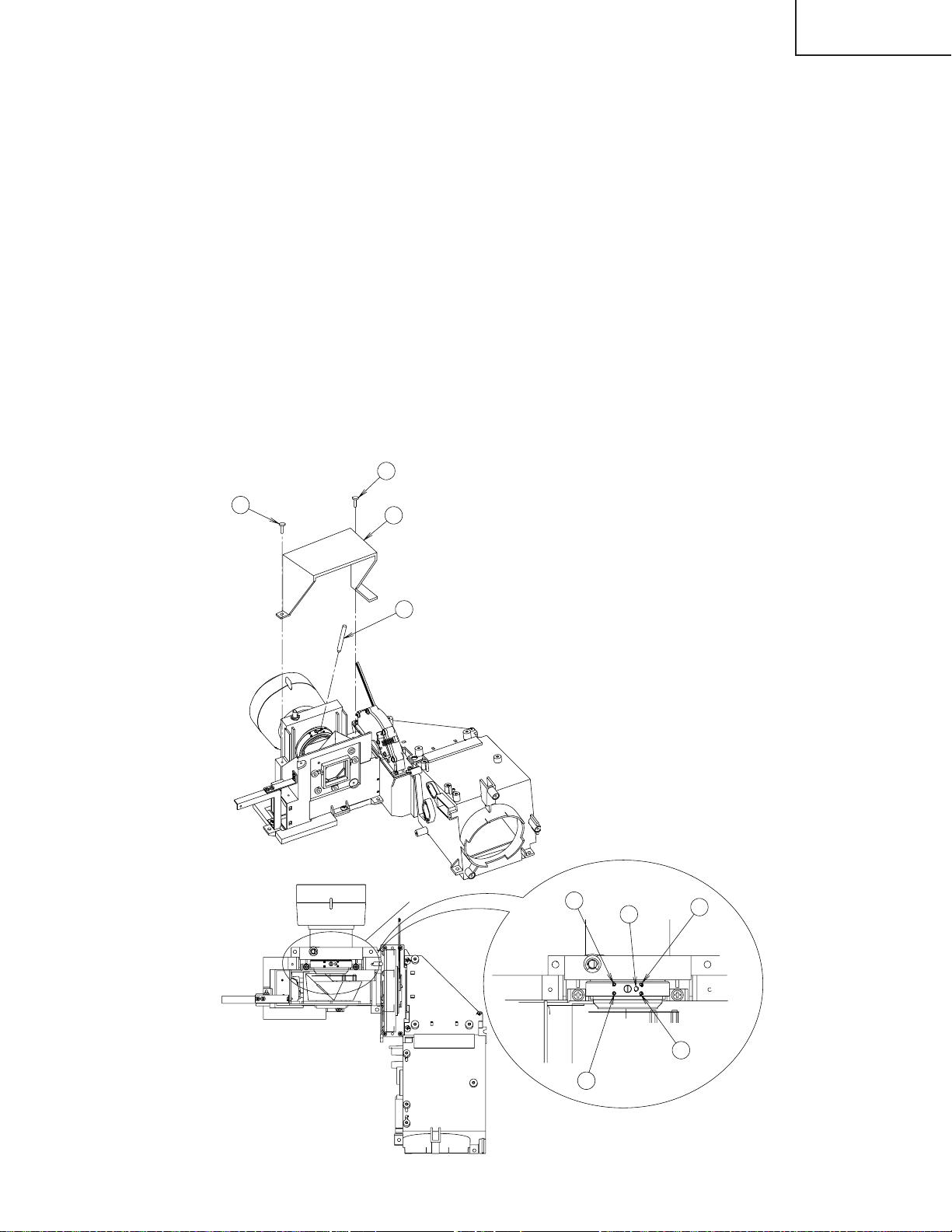
Adjusting the back focal distance after replacing the projection lens
Note: A piece of temporary tape is attached on the focus ring that comes with the replacement projection lens. Keep
this tape in place until the finish of the adjustment.
(1)Provide a distance of 2.4 m between the set and the screen and adjust the zoom knob to “wide end”.
(2)Adjust the lens shift until the projection lens comes to the same level as the center of the screen.
(3)Detach the optical unit top cover A from behind the projection lens.
(4)Loosen the four hex screws B in the back of the projection lens.
(5)Insert the adjustment screwdriver C (9EVDRIVERZ9000) in the hole D at the back of the lens. Put the center of the
screen in the best focus. (Preferably feed the SXGA signal for 1-dot white crosshatch pattern or 1-dot white dot
pattern on black background.)
(6)Tighten the four hex screws B to the torque of 0.3 Nm (3.06 kgfcm), and apply screw loctite to them.
(7)Peel the temporary tape off the focus ring of the projection lens.
(8)Attach the optical unit top cover A back into position. Finally fix the two screws E and apply screw loctite to them.
22
Page 23
XV-Z9000U/E
When the DMD unit has been replaced
Note: DMD chip and Formatter PWB are supplied at the same time, and an exchange only with DMD isn't done.Refer
to "REMOVING OF MAJOR PARTS" when exchanging Formatter PWB.
There is no need to readjust the back focal distance of the projection lens. If focusing is noticeably poor, however,
make this readjustment.
(1) Provide a distance of 2.4 m between the set and the screen.
(2) Adjust the lens shift until the projection lens comes to the same level as the center of the screen.
(3) Detach the optical unit top cover A from behind the projection lens.
(4) Loosen the four hex screws B in the back of the projection lens.
(5) Adjust the zoom knob at the front of the projection lens to “tele end” and ensure good focusing.
(6) Then adjust the zoom knob at the front of the projection lens to “wide end”.
(7) Insert the adjustment screwdriver C (9EVDRIVERZ9000) in the hole D at the back of the lens. Put the center of
the screen in the best focus. (Preferably feed the SXGA signal for 1-dot white crosshatch pattern or 1-dot white
dot pattern on black background.)
(8) Move the zoom knob from “wide end” back to “tele end” and see if focusing is ensured. If not, repeat the above
steps (5), (6) and (7) until the best focus is achieved.
(9) Tighten the four hex screws B to the torque of 0.3 Nm (3.06 kgfcm), and apply screw loctite to them.
(10) Attach the optical unit top cover A back into position. Finally fix the two screws E and apply screw loctite to them.
E
E
A
C
X
B
D
B
B
Expansion figure of part X
23
B
Page 24
XV-Z9000U/E
ELECTRICAL ADJUSTMENT
Hook up a signal generator, or a DOSV or Mac personal computer to the projector in order to feed the
signals specified in the Adjusting conditions.
No. Adjusting point Adjusting conditions Adjusting procedure
1 EEPROM
initialization
2 RGB drive
adjustment (on
the PC board)
3 DLP voltage
adjustment
(reference)
1. Turn on the power (with the
lamp on) and warm up the
set for 15 minutes.
1. Feed the 100% and 0% signals for each of the red,
green and blue colors.
INPUT5
2. Select the following group
and subject.
Group: A/D
Subject: R-D (R)
G-D (G)
B-D (B)
1. Keep out any signal input.
2. Select the following group
and subject.
Group: DLP
Subject: VOLTAGE
1. Make the following settings.
Press SW2002 to enter the process mode. Execute
the S2 and S4 commands on the SSS menu. With
the S2 command, all the circuit boards than the PC
board will be initialized. Do not activate the S1 command because otherwise the PC board itself will be
initialized.
(The delivered PC board has been factory-adjusted.)
If by any chance the PC board must be readjusted,
follow the instructions in "Adjusting the PC Board"
on page 28.
1. Using the control switches on the set or the buttons
on the remote control, adjust the setting until bit dropouts start at the white level.
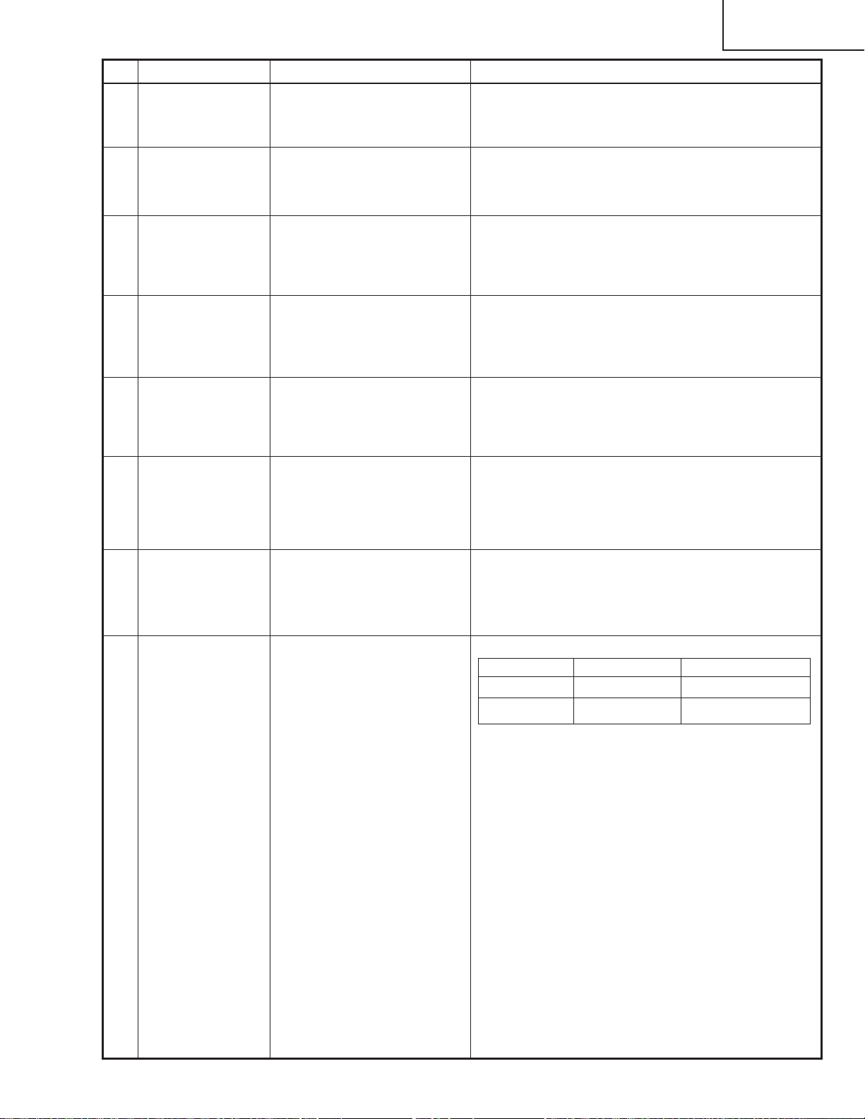
1. Select the setting of the rank marked on the formatter
PWB, referring to the menu.
2. Make this adjustment when the DLP chip has been
replaced or when the combination of DLP chip and
formatter PWB has been changed.
3. Rank B C D E
Setting 1 2 3 4
4 Color wheel
index adjustment
1. Feed the color wheel index
adjustment pattern signal.
INPUT5
2. Select the following group
and subject.
Group: DLP
Subject: CW INDEX
1. Adjust the setting so that the R, G and B lamp tone
pattern should be smooth without noises.
R
G
B
24
Page 25
No. Adjusting point Adjusting conditions Adjusting procedure
XV-Z9000U/E
5 RGB tone
reproduction
adjustment
6 Adjusting the
Background
Color
1. Feed the SMPTE pattern
signal.
INPUT5
2. Select the following group
and subject.
Group: DLP
Subject: R-BRIGHT
G-BRIGHT
B-BRIGHT
1. Select the following group
and subject.
Group: DLP
Subject: R-GAIN
G-GAIN
B-GAIN
2. Feed the Component
video, 75% white signal.
3. Signal level: 0.7±0.05 Vp-p
(sync section not included)
4. R-GAIN, G-GAIN and BGAIN initial settings: 95
5. Target chromaticity:
x = 0.272 ± 0.005
y = 0.310 ± 0.005
(color temperature 9500K+15 µV)
1. Make sure the 100% and 95% white and the 0%
and 5% black tones are visible.
2. If the black tone appears otherwise, finely adjust the
R-BRIGHT, G-BRIGHT and B-BRIGHT settings.
1. Project an image over a 40-inch screen and
measure the chromaticity at the center using a
chromaticity meter.
2. Keep the G-GAIN setting fixed at 95.
3. Adjust the B-GAIN setting to get the y value to its
target chromaticity.
4. Adjust the R-GAIN setting to get the x value to its
target chromaticity.
7 Video horizontal
center adjustment
8 Video BRIGHT-
NESS adjustment
9 Video picture
adjustment
10 Video tint
adjustment
1. Feed the NTSC monoscope pattern signal.
INPUT4
2. Select the following group
and subject.
Group: VIDEO 1
Subject: NTSC-H
1. Feed the NTSC 10-step
gray-scale signal.
2. Select the following group
and subject.
Group: VIDEO1
Subject: BRIGHT
1. Feed the NTSC 10-step
gray-scale signal.
2. Select the following group
and subject.
Group: VIDEO1
Subject: PICTURE
1. Feed the internal 8CH (split
color bar) signal.
INPUT4
2. Select the following group
and subject.
Group: VIDEO1
Subject: TINT
1. Using the control switches on the set or the buttons
on the remote control, adjust the setting until the
overscan should be equal at right and left.
1. Using the control switches on the set or the buttons
on the remote control, adjust the setting until more
bit dropouts start at the 0% black level.
1. Using the control switches on the set or the buttons
on the remote control, adjust the setting until bit dropouts start at the 100% white level.
1. Check the fixed setting.
Fixed setting: 128
25
Page 26
XV-Z9000U/E
No. Adjusting point Adjusting conditions Adjusting procedure
11 NTSC color
saturation
adjustment
1. Feed the internal 8CH (split
color bar) signal.
INPUT4
2. Select the following group
and subject.
Group: VIDEO1
Subject: N-COLOR
1. Check the fixed setting.
Fixed setting: 105
12 PAL color
saturation
adjustment
13 SECAM color
saturation
adjustment
14 DTV BRIGHT-
NESS adjustment
(Take this
procedure for
Model XVZ9000U only.)
1. Feed the P AL color bar signal.
INPUT4
2. Select the following group
and subject.
Group: VIDEO1
Subject: P-COLOR
1. Feed the SECAM color bar
signal.
INPUT4
2. Select the following group
and subject.
Group: VIDEO1
Subject: S-COLOR
1. Feed the 100% color bar
signal (component signal)
or the 10-step gray scale
signal to the input terminal
480I.
INPUT2
2. Select the following group
and subject.
Group: DVD
Subject: BRIGHT
1. Check the fixed setting.
Fixed setting: 110
1. Check the fixed setting.
Fixed setting: 110
1. Using the control switches on the set or the buttons
on the remote control, adjust the setting until more
bit dropouts start at the 0% black level.
15 DTV CONTRAST
adjustment
(Take this
procedure for
Model XVZ9000U only.)
16 DVD color
saturation
adjustment
DVD tint adjustment
1. Feed the 100% color bar
signal (component signal)
or the 10-step gray scale
signal to the input terminal
480I.
INPUT2
2. Select the following group
and subject.
Group: DVD
Subject: CONTRAST
1. Feed the 100% color bar
signal (480I component
signal) to the Y, Pb and Pr
input terminals.
INPUT2
2. Select the following group
and subject.
Group: DVD
Subject: COLOR
TINT
1. Using the control switches on the set or the buttons
on the remote control, adjust the setting until bit dropouts start at the 100% white level.
1. Check the fixed settings.
Fixed setting: TINT at 32
COLOR at 36
26
Page 27
No. Adjusting point Adjusting conditions Adjusting procedure
XV-Z9000U/E
17 White balance
checking and
readjustment
18 Color-related
performance
checking
19 Video-related
performance
checking
20 RGB-related
performance
checking
21 Off-timer per-
formance
performance
checking
1. Take the adjustment conditions discussed for Item
Make sure there is no white balance difference between the set and the standard monitor.
11 .
1. Feed the color bar signal. 1. Select L1 from the process mode LINE.
Check the Color and Tint performance.
1. Feed the monoscope pattern signal.
1. Select L2 from the process mode LINE.
Check the Picture, Brightness and Sharpness performance.
1. Feed the RGB signal. 1. Select L4 from the process mode LINE.
Check the Picture, Brightness, Red, Blue, Clock,
Phase, H-Position and V-Position performance.
1. Select OFF from the process mode LINE.
Make sure the off-timer starts with 5 minutes
onscreen and the set turns itself off in 5 minutes.
1. Heat the thermistor with a
1. Make sure that the temperature is indicated.22 Thermistor
hair dryer.
23 Auto sync
performance
checking
24 Delivery set-
tings
1. Feed the phase check pattern signal.
1. In the VGA, SVG Aand XGAmodes, make sure the
Clock, Phase, H-Pos and V-Pos settings can be automatically adjusted.
1. Make the following settings.
Destination Adjustment process Remote control setting
XV-Z9000U S4 Factory setting 4
XV-Z9000E S3 Factory setting 3
27
Page 28

XV-Z9000U/E
Adjusting the PC Board
1. Initializing the EEPROM
1) Press SW2002 to enter the process mode.
2) Execute the S1 command on the SSS menu. (The S1 command initializes the PC board alone. Do not
execute the S2 command because otherwise the adjustment data other than the PC board will be initialized.)
3) Make sure that the program version VER.XXX on the SPECIAL menu is the latest one.
2. Adjusting the levels
2.1 Setting the oscilloscope
Set the oscilloscope range to DC 1V/div. and 5 µsec/div.
2.2 Connecting the PC interface
1) Connect the specified cable between the analog output jack (signal generator) and the DUSB connector
(INPUT5 of the projector). Set the projector’s input selector to INPUT5.
2) Set the signal generator to the XGA mode (1024x768, 60 Hz, 32 tones). Adjust the output amplitude to 700
mVp-p between the black and white levels (terminated with a 75-ohm impedance).
3) Turn on the power.
2.3 Adjusting and checking the levels
1) Press SW2002 to enter the process mode.
2) Adjust the R-BRIGHT setting of Group A/D until bit dropouts start at the black level of the red signal.
3) Adjust the B-BRIGHT setting of Group A/D until bit dropouts start at the black level of the blue signal.
4) Adjust the G-BRIGHT setting of Group A/D until bit dropouts start at the black level of the green signal.
2.4 Adjusting the DTV
1) Feed the signal to the INPUT2’s RCA input terminal.
2) Set the signal generator to the 1080i 60-Hz mode with white signal. Adjust the output amplitude to 700 mVp-
p between the black and white levels.
3) Connect the specified cable between the analog output (signal generator) and the RCA connector (INPUT2
of the projector).
4) Make the G-BRIGHT setting the same as the G-BRIGHT setting of Group A/D.
5) Adjust the CB-OFFSET setting of Group DTV to 20.
6) Adjust the CR-OFFSET setting of Group DTV to 20.
7) When the CB-OFFSET and CR-OFFSET settings have been made, add 5 points to the G-BRIGHT setting for
Model XV-Z9000U and 4 points for Model XV-Z9000E.
8) Finally press SW2002 to exit from the process mode.
28
Page 29
Process menu 1
Group Sub Group Subject
Adjust PC Image A/D R-BRIGHT
G-BRIGHT
B-BRIGHT
R-D
B-D
G-D
Adjust HDDE formatter DLP VOLTAGE
CW-INDEX
R-BRIGHT
G-BRIGHT
B-BRIGHT
R-GAIN
G-GAIN
B-GAIN
XV-Z9000U/E
Adjust Component DTV G-BRIGHT
(High Definition) CB-OFFSET
CR-OFFSET
Adjust VIDEO Image VIDEO1 NTSC-H
PICTURE
BRIGHT
TINT
N-COLOR
P-COLOR
S-COLOR
SET UP
SET UP B
SET UP C
VIDEO2 PEAK FIL
PEAK GAIN
PEAK COR
N358 DLY
N433 DLY
PAL DLY
SECAM DLY
Adjust Component DVD CONTRAST
(480i) BRIGHT
TINT
COLOR
29
Page 30
XV-Z9000U/E
Process menu 2
Group Sub Group Subject
Process mode LINE L1
INITIAL SETTING SSS TIME
L2
L3
L4
OFF
TEMP OFF
SENSOR CHECK
S1
S2
S3
S4
S5
LAMP
Sample Pattern PATTERN RGB
RGB(50)
CROSS
STEP
COLOR
CHR
Adjust CVIC CVIC MODDE
-PROGRESSIVE IP
FILM
PTG
MSW
LSW
C-LEVEL
C-LIMIT
C-LPF
C-THRESH
C-MISSTH
C-MOVIEA
C-MOVIEB
C-MOVIEC
30
Page 31

Process menu 3
Group Sub Group Subject
Adjust CVIC CVIC BBN-TBL0
-ENHANCE-VIDEO BBN-TBL1
DFC-TBL0
DFC-DIR0
DFC-EDG0
DFCTBL1
DFC-DIR1
DFC-EDG1
CVIC BBN-TBL0
-ENHANCE-HDTV BBN-TBL1
DFC-TBL
DFC-DIR
DFC-EDG
CVIC BBN-GAIN0
XV-Z9000U/E
-ENHANCE-RGB BBN-GAIN1
BBN-GAIN2
BBN-TBL
DFC-TBL
DFC-DIR
DFC-EDG
CVIC CUBIC-RGB
-SCREEN CUBIC-VIDEO
CVIC XEGTH
-IDC XLTH1-H
XLTH1-L
XLTH2-H
XLTH2-L
VEGTH
VLTH1-H
VLTH1-L
VLTH2-H
VLTH2-L
Version Check etc. Special IPL
(High Definition) E2PROM
ADR RD/RW
31
Page 32

XV-Z9000U/E
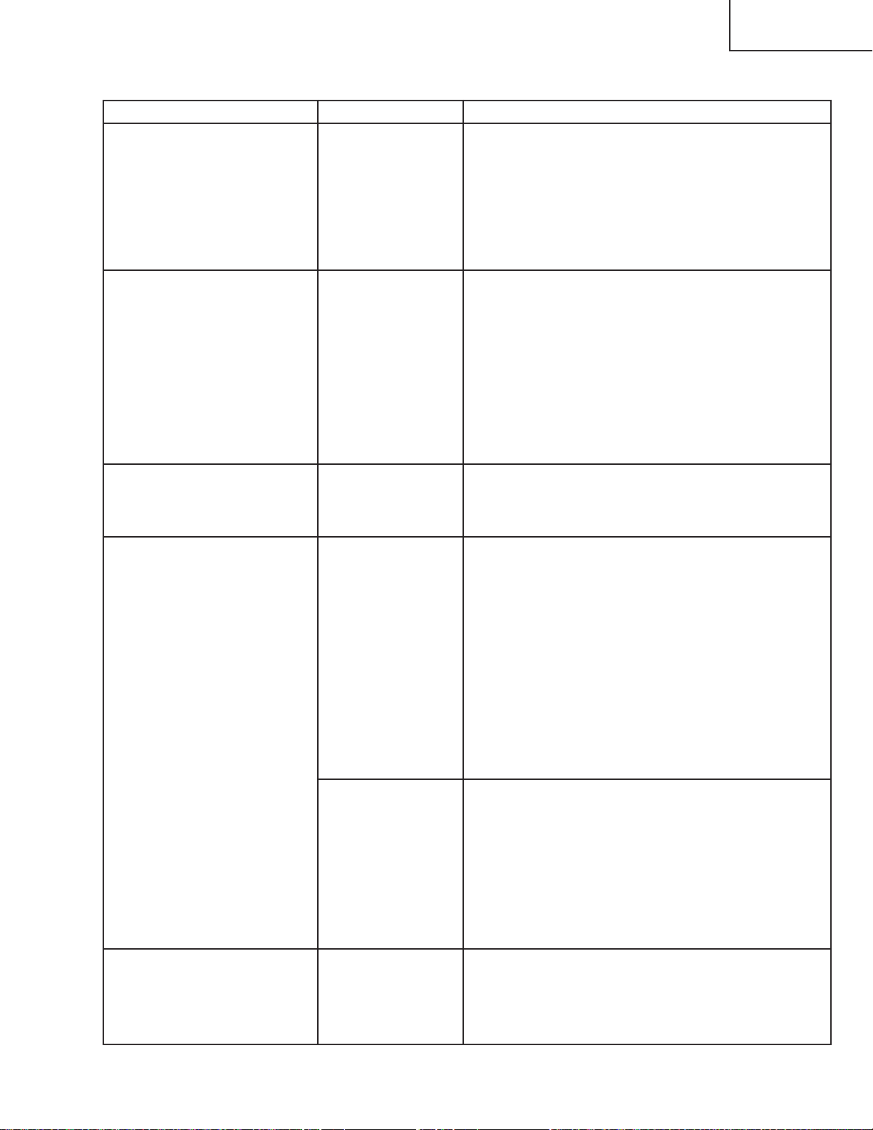
TROUBLE SHOOTING TABLE
Checking the basic
performance
Is the POWER LED on or
flickering in red or blue?
YES
Is the set turned on by the
set's or remote controller's
power key?
YES
Is the cooling fan
running? Is the lamp on?
YES
Is the user menu
displayed?
YES
Is the video input as
specified?
YES
Is the component input as
specified?
YES
If the RGB input as
specified?
YES
NO
NO
NO
NO
NO
NO
NO
Go to "Checking the
power unit"
Go to "Checking the
microcomputer
peripherals" and
"Checking the PC PWB".
Go to "Checking the lamp
light-up".
Check the formatter
circuit’s peripheral circuits.
Are there output signals at
pins (32), (34) and (37) of
P3580?
Are there output signals at
every other pin from pins
(41) to (60) of P3580?
Check the PC board
circuit’s peripheral circuits.
NO
NO
Check the IC2505 circuit
and its peripheral circuits.
Check the IC2505 circuit
and its peripheral circuits.
Does the RS-232C
interface function?
YES
Recommended
communication software:
“TERA TERM”
Make the following settings:
baud rate at 9600 bps, bit
length at 8 bits, stop bit at 1
bit and no parity. Press the
RETURN key on the
keyboard. Does “ERR”
show up again?
YES
END
NO
NO
Are there output signals at
every other pin from pins
(41) to (60) of P3580?
Are there output signals
at pins (32), (34) and (37)
of P3580?
32
NO
NO
Check the IC2505 circuit
and its peripheral circuits.
Check the IC2005 circuit
and its peripheral circuits.
Page 33

Checking the power unit
XV-Z9000U/E
Are all the connectors
inside the power unit tightly
connected?
YES
Is the lamp cover closed
completely?
YES
Is the bimetal switch off?
YES
Is AC voltage applied
across the RL7001 relay?
YES
Is AC voltage applied
across L7005?
YES
NO
Insert the connectors
CN7105, 7103, 7101AND
7102 tightly.
NO
Tighten up the lamp door
closed with the screws.
NO
Replace the bimetal switch
or press the red button to
reset.
NO
Replace F7001.
NO
Replace F7002.
Is there DC voltage of
about 6 V across C7151?
YES
Is there DC voltage of
about 340 V across
CN7003?
YES
Are there the specified
voltages at the output
terminals of CN7101 and
CN7102?
YES
Check the output PWB
circuits.
NO
Check the peripheral
circuits of Q7101~Q7107.
Replace any of them as
required.
NO
Check the circuits leading
to the primary side of
T7002 for damage.
Replace any of them as
required.
NO
Check the circuits leading
to the secondary side of
T7002 for damage.
Replace any of them as
required.
33
Page 34

XV-Z9000U/E
Checking the PC PWB
0
Is the user menu properly
displayed?
NO
Check the on-screen
display.
Check the DTV RGB
input.
Check the DTV
component input.
Check the VIDEO input.
YES
Check the basic signal flow. The signal flow from
CVIC_IC to the panel output is the same for the
component and video signals. Therefore the lines
after CVIC are not checked. (The 480i and 580i
component signals are not included.)
The signal flows through the same circuits as the
DTV RGB signal does. Check the SOG (Sync On
Green) circuit and the color adjustment circuit. (The
480i and 580i component signals are not included.)
The video signal flows through a different route from
the RGB input signal, and goes into CVIC_IC.
Therefore check the video signal ICs.
Check the D-SUB input.
Check the D-SUB input.
End
34
Page 35

XV-Z9000U/E
YES
YES
NO
YES
Checking the RGB input
Feed the sync-separated DTV
RGB signal to INPUT1 or
INPUT2. (The 480i and 580i
component signals are not
included.)
Check to see if the video input is
as specified.
Is the contour as specified?
Using the front-panel key or
the remote control, select
INPUT1 or INPUT2.
NO
NO
Is the image disturbed?
Go to "Checking the sync signal".
Do R, G and B colors appear?
Go to "Checking the RGB signal".
NO
IC8004 or its peripheral circuit
defective.
End
YES
Does the image appear?
1
2
3
35
Page 36

XV-Z9000U/E
Checking the video input
Make sure the input signal
setting is as specified.
YES
Is there the video signal at
the land of C8077?
YES
Check the sync signal.
YES
IC8025 or IC8004
defective.
Checking the input signal
setting
Is the input signal setting
as specified?
YES
NO
Input PWB defective.
NO
Select the specified signal.
Is the connector properly
connected?
YES
End
2
NO
Reconnect the connector.
1
36
Page 37

Checking the sync signal
XV-Z9000U/E
Is there vertical sync signal
at TL8134?
YES
Is there horizontal sync
signal at TL8133?
YES
Is there vertical sync signal
at TL8131?
YES
Is there horizontal sync
signal at TL8130?
YES
NO
NO
Check the input signal
setting.
Input PWB defective.
NO
NO
IC8302, IC8325, IC8299 or
their peripheral circuits
defective.
Are both the vertical and
horizontal sync signals
timely?
YES
Is the signal generator
(input source) as
specified?
YES
Input PWB defective.
NO
There is no problem with
the sync signal.
End.
NO
Make the specified signal
source settings.
2
37
Page 38

XV-Z9000U/E
Checking the RGB signal
Is the type of signal set at
RGB?
NO
Call the process mode.
Select R, G and B
separately on the pattern
menu.
Go to “Checking the GA4
peripheral circuits”.
Set the signal generator to
the gradation signal mode
in order to check the input
signal.
Measure the gradation
signals at TL8073, T8074,
T8075 and T8080.
YES
Set to the RGB signal.
Are there specified signals
at TL8073, TL8074,
TL8075 and TL8080?
YES
IC8025 or its peripheral
circuit defective.
NO
Are there input signals at
C8069 and C8061?
YES
IC8004 or its peripheral
circuit defective.
NO
Input PWB defective.
38
Page 39

Checking the GA4
peripheral circuits
Call the process mode, and
select R, G and B
separately on the pattern
menu.
XV-Z9000U/E
Are there specified R, G
and B video output signals?
NO
Are the measured signals
the same as the signals
selected on the pattern
menu?
NO
Is there clock signal at
R974?
YES
Are there sync signals at
TL8026, TL8027 and
TL8028?
YES
Using the oscilloscope,
measure the signals at
TL8141 thru TL8148.
YES
YES
NO
NO
End of checking the GA4
peripheral circuits.
Output PWB defective.
Is there clock signal
(37.125 MHz) at TL8114?
NO
Is there clock signal
(37.125 MHz) at FL8110?
YES
IC8025 defective.
Are there sync signals at
TL8112 and TL8133?
YES
IC8029 defective.
YES
IC8029 defective.
NO
X8005 defective.
NO
IC8025 defective.
Are the measured signals
the same as the signals
selected on the pattern
menu?
YES
Using the oscilloscope,
measure the signals at
TL8106 thru TL8111.
Are the measured signals
the same as the signals
selected on the pattern
menu?
YES
IC8029 defective.
NO
Digital panel PWB
defective.
NO
IC8025 defective.
39
Page 40

XV-Z9000U/E
Checking the
component inputs
(Except for 480I)
Feed the component signal
to INPUT1 or INPUT2.
Using the front panel key
or the remote control,
select INPUT1 or INPUT2.
Does an image appear on the
screen?
4
Are the colors as
specified?
Is the type of signal set at
COMPONENT?
Carry out the process
adjustment.
YES
NO
NO
NO
4
NO
Go to "Checking the
SOG circuit".
YES
YES
Set the type of signal to
COMPONENT.
Is the image contour as
specified?
NO
End of checking the
component input.
YES
IC8004 or IC8025
defective.
40
Page 41

Checking the SOG circuit
Measure the signal at
TL8136 on the
oscilloscope.
XV-Z9000U/E
Is the composite sync
signal played back timely?
NO
Measure the land of C8069
on the oscilloscope.
Is there the Y signal
including the sync signal?
YES
SOG sync separation
circuit defective.
Checking the on-screen
display.
Is the on-screen display
color as specified?
YES
There is no problem with
the SOG circuit. End.
NO
Go to “Checking the input
signal settings”.
Input PWB defective.
YES
NO
Carry out the output line
adjustment in the
adjustment process.
0
Go to “Checking the GA4
peripheral circuits”.
Get the flash ROM
reprogrammed.
41
Page 42

XV-Z9000U/E
5
Checking the video input
Feed the composite video
signal to INPUT4.
Using the front panel key
or the remote control,
select INPUT4.
Select VIDEO as the type
of signal on the user menu.
Does the image appear?
YES
Is the image disturbed?
NO
Is the contour as specified?
YES
There is no problem with
the video input. End.
Is there the video signal at
pin (72) of IC8338?
NO
YES
NO
NO
Go to "Checking the video
sync signal".
Go to "Checking the video
sync signal".
Carry out the process
adjustment.
5
Is the video signal as
specified?
NO
6
YES
IC8338 defective.
42
Page 43

6
Measure the VPC (IC8338)
clock signal at TL8004.
XV-Z9000U/E
Is the clock signal as
specified?
YES
Go to “Checking the video
sync signal”.
IC8025 or its peripheral
circuit defective.
Checking the video sync
signal
Using the oscilloscope,
measure the signal at
TL8140. (Check the
vertical sync signal.)
NO
IC8338 defective.
Is the vertical sync signal
as specified?
YES
Using the oscilloscope,
measure the signal at
TL8142. (Check the
horizontal sync signal.)
Is the horizontal sync
signal as specified?
YES
7
NO
NO
Go to "Checking the input
signal setting".
Input PWB defective.
43
Page 44

XV-Z9000U/E
Checking the DSUB input.
Feed the PC-RGB signal to INPUT5.
Select INPUT5 as the input.
Does the image appear?
YES
Check to see if there are the R, G
NO
and B signals at pins (126), (136)
and (146) of IC8004.
Is there any distortion with the image?
NO
3
Check the vertical and horizontal sync
signals at pin (6) of IC8364 and pin (6)
of IC8385.
Are the sync signals as specified?
YES
Are there the horizontal and vertical sync
signals at TL8130 and TL8131?
YES
YES
NO
NO
Are there the R, G and B signals?
YES
Sync separation circuit, IC8354m
IC8365 or their peripheral circuit
defective.
IC8302 or its peripheral circuit
defective.
NO
DSUB connector
or its peripheral
part defective.
IC8025, IC8004 or their peripheral
circuit defective.
44
Page 45

Checking the lamp
light-up
The lamp fails to light up.
XV-Z9000U/E
Is discharge sound heard
when turning on the power
switch?
NO
Are the cooling fans
running well?
YES
Is a voltage of about DC
340 V applied across the
ballast power circuit
CP1001?
YES
Is a voltage of over 3.5 V
applied at pin (1) of the
ballast power circuit
CP1501?
YES
Check the
microprocessor circuit.
Replace the ballast power
PWB.
YES
NO
NO
NO
Is the lamp or CW line
socket out of position?
YES
Replace the lamp or the
CW.
Check the power circuit
or the fan circuit on the
main circuit.
Check the power circuit.
Replace the ballast power
PWB. Check the
microprocessor circuit.
NO
Reconnect the sockets
tightly.
45
Page 46

XV-Z9000U/E
No horizontal
synchronization
Is the terminal input
connection as specified? Is
the cable tightly
connected?
NO
YES
Use the specified cable.
Reconnect it tight enough.
Is there the horizontal sync
pulse at pin (14) of
IC2506?
YES
Is there the horizontal
sync pulse at pin (11) of
IC2509?
YES
Go to "PC Board
Troubleshooting".
No vertical
synchronization
Is the terminal input
connection as specified? Is
the cable tightly
connected?
NO
NO
Check the line between
IC2506 and the input
terminal.
NO
Check the line between
IC2506 and IC2509.
YES
Use the specified cable.
Reconnect it tight enough.
Is there the vertical sync
pulse at pin (14) of
IC2501?
YES
Is there the vertical sync
pulse at pin (8) of
IC2509?
YES
Go to "PC Board
Troubleshooting".
NO
Check the line between
IC2501 and the input
terminal.
NO
Check the line between
IC2506 and IC2509.
46
Page 47

Checking IC3504 (3D
Noise Reduction) and its
Peripheral Circuits
XV-Z9000U/E
Are there the input signals
at pins (88) (Y signal) and
(96) (C signal) of IC3504?
YES
Are there the output
signals at pins (84) (Y
signal) and (83) (C signal)
of IC3504?
YES
Check the line up to the
PC board connector or
the circuits that follow the
PC board.
NO
Check the signal input
circuit or IC2505 and its
peripheral circuits.
NO
Check IC3504 and its
peripheral circuits.
47
Page 48

XV-Z9000U/E
Checking the
Component and RGB
Inputs
Are there signals at pins
(34), (36) and (38) of
IC2505?
YES
Are there signals at pins
(3), (5) and (6) of IC2507?
YES
Are there signals at pins
(56/26), (58/28) and
(60/30) on the board-toboard section of P3580?
YES
NO
NO
NO
Check the signal input
circuit or IC2505 and its
peripheral circuits.
Check the line between
Q2509 and Q2517 and its
peripheral circuits, or
IC2507.
Check the line between
Q2518 and Q2520 and its
peripheral circuits.
NO
There are no RGB colors.
YES
Check the circuit of the
color that fails to appear.
NO
There are no RGB colors.
YES
Check the circuit of the
color that fails to appear.
Are there signals at pins
(49/19), (51/21) and
(53/23) on the board-toboard section of P3580?
YES
Check the board-to-board
connections or the
circuits that follow the PC
board.
NO
Check the line from
Q2525 through Q2523 to
Q2524 and its peripheral
circuits.
48
Page 49

Technische Daten
XV-Z9000U/E
Produkttyp
Modell
Videosystem
Display-Verfahren
DMD-Feld
Linse
Projektionslampe
Videoeingangssignal
S-Videoeingangssignal
Komponenten-
Eingangssignal
Horizontal-Auflösung
RGB-Eingangssignal
Punkatetakt
Vertikale Frequenz
Horizontale Frequenz
Computersteuerungs-Signal
Nennspannung
Eingangsspannung
Nennfrequenz
Stromaufnahme
Stromverlust
Betriebstemperatur
Lagertemperatur
Gehäuse
I/R-Trägerfrequenz
Abmessungen (ca.)
Gewicht (ca.)
Mitgeliefertes Zubehör
Ersatzteile
Projector
XV-Z9000E
PAL/PAL 60/PAL-M/PAL-N/SECAM/NTSC 3.58/NTSC 4.43
DTV 480i/480P/720P/1080i
Single Panel Digital Micromirror Device (DMD™) von Texas Instruments, RGB optisches
Verschlussverfahren
Feldformat: 0,8"
Antriebsverfahren: Digital Light Processing (DLP™) von Texas Instruments
Anzahl der Punkte: 921.600 Punkte (1.280 [H] × 720 [V])
1 –1,35 Zoom-Linse, F3,0,f=32,5 –44,0 mm
250 W NSH-Lampe
RCA-Stecker: VIDEO (INPUT 4), Gemischtes Video, 1,0 Vp-p, negatives Sync.-Signal, 75
Ω terminiert
4-Pin Mini DIN-Stecker (INPUT 3)
Y (Luminanz-Signal): 1,0 Vp-p, negatives Sync.-Signal, 75Ω terminiert
C (Chrominanz-Signal): Stoß 0,286 Vp-p, 75Ω terminiert
RCA-Stecker (INPUT 1, 2)
Y: 1,0 Vp-p, negatives Sync.-Signal, 75Ω terminiert
CB: 0,7 Vp-p, 75Ω terminiert
CR: 0,7 Vp-p, 75Ω terminiert
520 TV-Zeilen (NTSC 3,58 Eingang), 750 TV-Zeilen (DTV 720P Eingang)
15-PIN MINI D-SUB STECKANSCHLUSS (INPUT 5):
RGB getrennt/gemischte Sync./Sync. auf Grün-Typ analoger Eingang: 0–0,7 Vp-p,
positiv, 75Ω terminiert
HORIZONTALES SYNC.-SIGNAL: TTL-Pegelsignal (positiv/negativ) oder gemischtes Sync.-Signal
(nur Macintosh)
VERTIKALES SYNC.-SIGNAL: Wie oben
12–120 MHz
43–100 Hz
15–81 kHz
9-Pin D-Sub-Steckanschluß (RS-232C-Eingangs-Port)
100–240 V Wechselstromspannung
3,6 A
50/60 Hz
345 W (Wenn in “Kinofilm-Modus” “HELLIGK.” angewählt ist)
310 W (Wenn in “Kinofilm-Modus” “NORMAL” angewählt ist)
1.400 BTU/Stunde
+5°C bis +35°C
-20°C bis +60°C
Kunststoff
38 kHz
475 × 178 × 406 mm (B × H × T) (nur Hauptgerät)
475 × 178 × 496 mm (B × H × T) (einschließlich Buchsenabdeckung)
9,5 kg (nur Hauptgerät)
Fernbedienung, Zwei AA-Batterien, Netzkabel (1,8 m), 21-Pin RCA-Konversionsadapter,
Video-Kabel, RGB-Kabel, Buchsenabdeckung, Linsenkappe (aufgesetzt), CD-ROM, Zwei
Projektor-Bedienungsanleitungen, SharpVision Manager-Bedienungshandbuch
Lampeneinheit (Lampe/Gehäusemodul) (BQC-XVZ9000/1), Fernbedienung
(RRMCG1657CESA), AA-Batterien, Netzkabel (QACCV4002CEZZ, QACCB5024CENA),
21-Pin RCA-Konversionsadapter (QSOCZ0361CEZZ), Video-Kabel (QCNWGA001WJZZ),
COMPUTER-RGB-Kabel (QCNW-5050CEZZ), Buchsenabdeckung (GCOVA1985CEKA),
Linsenkappe (PCAPH1056CESA), CD-ROM (UDSKA0047CEN1), Zwei ProjektorBedienungsanleitungen(TINS-7521CEZZ, TINS-7522CEZZ), SharpVision ManagerBedienungshandbuch(TINS-7523CEZZ)
Dieser SHARP-Projektor verwendet einen DMD-Chip. Dieser
hochentwickelte Chip beinhaltet 921.600 Pixel. Wie bei allen
hochtechnologischen Elektronikgeräten wie großen
Fernsehbildschirmen, Videosystemen und Videokameras, gibt es
auch hier bestimmte akzeptable Toleranzen, denen das Gerät
entsprechen muß.
Änderungen der technischen Daten ohne vorherige Ankündigung vorbehalten.
Dieses Gerät hat einige inaktive Pixel innerhalb akzeptabler
Toleranzen, die in inaktiven Punkten auf dem Bildschirm resultieren.
Dies hat keinen Einfluß auf die Bildqualität oder die Lebensdauerdes
Gerätes.
49
Page 50

XV-Z9000U/E
5
5
HINWEIS FÜR DAS
WARTUNGSPERSONAL
234567890123456789012345678901212345678901234
ACHTUNG: UV-STRAHLUNG
234567890123456789012345678901212345678901234
Die Beleuchtungsquelle des LCD-Projektors, eine
UHP-Lampe, emittiert eine geringe Menge
UV-Strahlung.
DIREKTE BESTRAHLUNG AUF AUGEN
UND HAUT MUSS VERMIEDEN WERDEN.
Zur Gewährleistung der Sicherheit muß folgendes
beachtet werden:
1. Bei Arbeiten am Projektor bei eingeschalteter
Lampe und abgenommenem oberen Gehäuse muß
unbedingt eine Sonnenbrille getragen werden.
Auswechseln der Lampe
Hinweis:
Da die Lampe während des Betriebs sehr heiß wird,
sollte die Lampe erst ausgewechselt werden, nachdem
das Gerät mindestens eine Stunde ausgeschaltet war ,
damit die Lampe ausreichend abkühlen kann.
Beim Installieren der neuen Lampe muß darauf
geachtet werden, die Lampe selbst (Glaskolben)
nicht zu berühren. Vielmehr muß die Lampe am
Reflektor 2 gehalten werden.
[Es darf nur ein Original-Ersatzteil verwendet
werden.]
Lampe
1
Reflektor
2
2. Die Lampe darf nicht außerhalb des
Lampengehäuses eingeschaltet werden.
3. Betrieb für länger als 2 Stunden bei
abgenommenem Gehäuse ist nicht zulässig.
Zur Beachtung bei UV-Strahlung
und Mitteldruck-Lampen
1. Vor dem Auswechseln der Lampe muß der
Netzstecker gezogen werden.
2. Vor Durchführung von Wartungsarbeiten muß das
Gerät eine Stunde abkühlen.
3. Die Lampe darf nur gegen eine der gleichen Art
ausgewechselt werden. T yp BQC-XVZ9000/1,
bemessen für 355 V/250 W.
4. Die Lampe gibt eine geringe UV-Strahlung ab,
daher muß direkter Augenkontakt vermieden
werden.
5. Die Mitteldruck-Lampe weist ein Explosionsrisiko
auf. Daher müssen die nachstehenden
Installationsanweisungen beachtet werden, und die
Lampe muß vorsichtig behandelt werden.
GEFAHR! — Niemals die Spannungsversorgung
einschalten, ohne daß eine Lampe vorhanden ist,
um elektrische Schläge und Schäden am Gerät zu
vermeiden, da der Stabilisator anfangs hohe
Spannungen erzeugt.
Da eine geringe Menge UV-Strahlung an der Öf fnung
zwischen den Lüftern austritt, wird empfohlen,
während der Wartungsarbeiten die Abdeckkappe des
Zusatzobjektivs an dieser Öffnung anzubringen, um
Augen und Haut vor den UV-Strahlen zu schützen.
50
Page 51

Lage der Bedienelemente
Linsenversteller
Zoom-Knopf
Fokusring
Einsteller
Temperaturwarnanzeige
(TEMPERATURE WARNING)
Lampenaustausch-Anzeige
(LAMP REPLACEMENT)
Netzanzeige (POWER)
Einlass-Lüftungsöffnung
Einsteller
Fernbedienungssensor
Linsenkappe
Einstelltasten (ADJUSTMENT)
('/"/\/|)
Eingabetaste
(ENTER)
Rückgängig-Taste
(UNDO)
Menü-Taste (MENU)
Skalierungstaste (RESIZE)
Eingangstaste (INPUT)
Netztasten (POWER)
Ein/Aus (ON/OFF)
Seiten- und
Rückansicht
Ansicht von vorne
und oben
Projektor
XV-Z9000U/E
51
Page 52

XV-Z9000U/E
Projektor
Seiten- und
Rückansicht
Einlass-Lüftungsöffnung
Auslass-Lüftungsöffnung
Fernbedienungssensor
Eingang 5 Computer-RGB-Port
(INPUT 5 COMPUTER-RGB)
(15poliger Mini-D-Sub)
S-Video-Eingang 3-Buchse
(S-VIDEO INPUT 3) (4poliger Mini DIN)
Eingang 1 Komponente / RGB-Buchsen
(INPUT 1 COMPONENT / RGB) (RCA)
Einlass-Lüftungsöffnung
RS-232C-Port(9poliger D-Sub)
12 V Gleichstrom-Ausgang
(DC 12V OUTPUT)
Wechselstrom-Buchse
Eingang 2 Komponenten / RGB-Buchsen
(INPUT 2 COMPONENT / RGB) (RCA)
Video-Eingang 4-Buchsen
(VIDEO INPUT) (RCA)
52
Eingangsbuchse für
Drahtfernbedienung
12 V Gleichstrom 200 mAAusgangsbuchse (OUTPUT)
Page 53

Fernbedienung
Netztasten (POWER)
Ein/Aus (ON/OFF)
Eingabetaste (ENTER)
Rückgängig-Taste (UNDO)
Eingang 1-Taste (INPUT 1)
Eingang 2-Taste (INPUT 2)
Eingang 4-Taste (INPUT 4)
Kinofilm-Modus-Taste
(THEATER MODE)
GAMMA-Taste
Taste für automatische
Synchronisation
(AUTO SYNC)
XV-Z9000U/E
Vorderansicht
Menü-Taste (MENU)
Einstelltasten (ADJUSTMENT)
(\/|/'")
Eingang 3-Taste (INPUT 3)
Eingang 5-Taste (INPUT 5)
GRÖSSE ÄNDERN-T aste (RESIZE)
Farbtemperatur-Tasten (CLR TEMP)
Trapeztaste (KEYSTONE)
Hintergrundbeleuchtungs-Taste
(BACKLIGHT)
Ansicht von oben
Fernbedienungssignal-Sender
Einlegen der Batterien
Ziehen Sie die Lasche
1
auf der
Batterieabdeckung nach
unten und nehmen Sie
die Abdeckung in
Pfeilrichtung ab.
BatterieAbdeckung
Eingangsbuchse für
Drahtfernbedienung
Legen Sie zwei AA-
2
Batterien unter
Anpassung der im
Batteriefach
aufgezeigten (+)- und (–)Markierungen ein.
Batteriefach
Setzen Sie die untere
3
Lasche
der
Batterieabdeckung in die
Öffnung ein und drücken
Sie die Abdeckung
herunter, bis sie einrastet.
BatterieAbdeckung
53
Page 54

XV-Z9000U/E
s
Fernbedienung
Mit der Fernbedienung kann der Projektor innerhalb de
links aufgeführten Bereiches gesteuert werden.
45˚
30˚
Fernbedienung
7 m
45˚
30˚
30˚
• Für einfachen Betrieb kann das Signal von der
Fernbedienung von einem Bildschirmreflektiertwerden.
Dennoch variiert die effektive Signalentfernung
entsprechend des Bildschirmmaterials.
Benutzung der Fernbedienung in
einem dunklen Raum
Die Hintergrundbeleuchtung der Betriebstasten kann
durch Betätigung von BACKLIGHT für 5Sekunden
ein- und ausgeschaltet werden. Wenn Sie die
eingeschalteten Hintergrundbeleuchtungen
ausschalten möchten, drücken Sie noch einmal
BACKLIGHT.
Hintergrundbeleuchtungs-Taste
(BACKLIGHT)
Benutzung einer Drahtfernbedienung
Wenn die Fernbedienung aufgrund des Bereiches
oder der Positionierung des Projektors
(Rückprojektion usw.) nicht verwendet werden kann,
schließen Sie ein 3,5 mm Stereo-Minibuchsenkabel
3,5 mm StereoMinibuchsenkabel
(im Handel erhältich)
(im Handel erhältlich) von der DrahtfernbedienungsEingangsbuchse oben auf der Fernbedienung an die
sich auf der Rückseite des Projektors befindliche
Drahtfernbedienungs-Eingangsbuchse an.
54
Page 55

Pin-Belegung
INPUT 5 RGB-Signaleingangs-Port: 15-Pin Mini-D-Sub-Buchse
RGB-Eingang
Analog
1. Videoeingang (rot)
11
6
1
15
10
5
RS-232C-Anschlußstelle: 9-Pin D-Sub-Stecker des DIN-D-Sub RS-232C-Kabels
9 6
5
1
Pin Nr. Signal Name E/A Referenz
1 Nicht angeschlossen
2 RD Daten empfangen Eingang
3 SD Daten senden Ausgang
4 Reserviert
5 SG Signalerdung
6 Reserviert
7 Reserviert
8 Reserviert
9 Nicht angeschlossen
2. Videoeingang
(Grün/Sync. auf Grün)
3. Videoeingang (blau)
4. Nicht angeschlossen
5. Gemischtes Sync.-Signal
6. Erdung (rot)
7. Erdung (Grün/Sync. auf Grün)
8. Erdung (blau)
An internen Schaltkreis angeschlossen
An internen Schaltkreis angeschlossen
An internen Schaltkreis angeschlossen
An internen Schaltkreis angeschlossen
An internen Schaltkreis angeschlossen
An internen Schaltkreis angeschlossen
An internen Schaltkreis angeschlossen
XV-Z9000U/E
9. Nicht angeschlossen
10. MASSE
11. MASSE
12. Bi-direktionale Daten
13. Horizontales Sync.Signal
14. Vertikales Sync.-Signal
15. Daten-Zeitgeber
55
Page 56

XV-Z9000U/E
Abmessungen
Ansicht der
Rückseite
Seitenansicht
Ansicht von vorne
Ansicht von oben
Seitenansicht
Seitenansicht
406
178
Ansicht von unten
475
Einheit:mm
56
Page 57

ENTFERNEN DER HAUPTTEILE
1.Ausbau der oberen Abdeckung
1-1. Die sechs Sicherungsschrauben losdrehen.
1-2. An den seitlichen Pfeil A an der
Gehäuseunterseite hineindrücken und die hintere
Abdeckung anheben.
1-3. Den Stecker abziehen.
1-4. An den vorderen Pfeil B an der
Gehäuseunterseite hineindrücken und die
Sperrklinken aushaken. Danach die obere
Abdeckung abnehmen.
XV-Z9000U/E
2-1. Die beiden Schrauben losdrehen, dann die LED-
Platine entfernen.
2-2. Die Schraube losdrehen und die R/C-Platine
entfernen.
2-3. Die drei Schrauben losdrehen und die
Betriebsplatine entfernen.
Obere Abdeckung
2-1
2-2
LED-Platine
R/C Platine
2-3
Betriebsplatine
1-1
1-1
1-4
1-4
1-3
1-4
B
1-4
B
1-1
1-2
A
A
1-1
57
Page 58

XV-Z9000U/E
2.Ausbau des Kühlgebläses und der Platineneinheit
3-1. Die elf Stecker abziehen.
3-2. Die beiden Schrauben losdrehen und die Lampenfassung entfernen.
3-3. Die beiden Schrauben losdrehen und das Kühlgebläse entfernen.
3-4. Die vier Schrauben losdrehen und die Platineneinheit entfernen.
(J5) (J3) (DB1)
3-1
3-4
Platineneinheit
LAMPE
Door SW
Bi-Metal
3-1
3-4
3-1
3-4
(RC)(TA)
3-2
(J2)
(FD) (FB)
(FA)
3-3
Kühlgebläse
58
Page 59

XV-Z9000U/E
3.Ausbau der Rückwand, der PC-Einheit, des Kühlschachts und der
Hauptplatineneinheit
4-1. Die beiden Schrauben losdrehen.
4-2. Die drei Schrauben losdrehen und die Abdeckplatte entfernen.
5-1. Die beiden Schrauben losdrehen.
5-2. Die vier Sechskanthalterungen entfernen, dann die Abdeckplatte entfernen.
6-1. Die vier Schrauben losdrehen, dann die PC I/F-Einheit abnehmen.
7-1. Die vier Schrauben losdrehen, dann den Kühlschacht abnehmen.
8-1. Die beiden Sechskanthalterungen entfernen.
8-2. Die fünf Schrauben losdrehen und die Hauptplatine entfernen.
8-3. Die Halterung entsperren.
(TB) (EA)
(FC)
6-1
6-1
PC I/F-Einheit
Rückwand
4-1
Abdeckplatte
4-2
5-2
5-1
(EB)
(CA)
5-2
8-2
8-1
Hauptplatine
8-2
7-1
Kühlschacht
59
8-3
7-1
Page 60

XV-Z9000U/E
4.Entfernen der Netzteilabdeckung, der Netz-/Vorschaltgeräte-Einheit sowie
des Netzteils.
9. Die sieben Schrauben losdrehen und die Netzteilabdeckung entfernen.
10-1. Die beiden Schrauben losdrehen.
10-2. Die vier weißen Halter entfernen, dann das Netzteil abnehmen.
11. Die vier Schrauben losdrehen, dann das Netzteil entfernen.
10-1
Netzteilabdeckung
9
11
Vorschaltgerät
11
10-2
Netzteil
10-2
9
60
Page 61

5.Ausbau der Optikmechanismus-Einheit und der R/C-Platineneinheit
12. Die sechs Schrauben losdrehen und die Optikmechanismus-Einheit entfernen.
13. Die Schraube losdrehen und die R/C-Platineneinheit entfernen.
12
12
XV-Z9000U/E
Optikmechanismus-Einheit
12
13
R/C-Platineneinheit
61
Page 62

XV-Z9000U/E
6.Ausbau von Lampeneinheit, Farbeinstellscheiben-Gebläse, Auslaßgebläse,
Luftkanal, Abschirmblech und Bildformatiererplatine
14. Die drei Schrauben losdrehen und die Lampeneinheit entfernen.
15. Die beiden Schrauben losdrehen und das Farbeinstellscheiben-Gebläse entfernen.
16. Die drei Schrauben losdrehen und das Auslaßgebläse entfernen.
17-1. Die beiden Schrauben losdrehen und das Bimetall entfernen.
17-2. Die beiden Schrauben losdrehen und den Luftkanal entfernen.
18-1. Die sechs Schrauben losdrehen und das Abschirmblech (B) entfernen.
18-2. Die drei Schrauben losdrehen und die Bildformatiererplatine entfernen.
18-3. Die drei Schrauben losdrehen und das Abschirmblech (A) entfernen.
Abschirmblech (A)
17-2
Bildformatiererplatine
Abschirmblech (B)
Luftkanal
18-3
18-2
18-2
18-1
15
Bimetall
16
17-1
14
Auslaßgebläse
Lampeneinheit
62
Page 63

XV-Z9000U/E
Problem
• Die Lampe wurde über 1.900 Stunden
verwendet.
• Die Lampe wurde über 2.000 Stunden
verwendet.
Abhilfe
• Einen Austauschlampen-Satz
(Lampe/Käfigmodul) des
gegenwärtigen Typs BQCXVZ9000/1 beim nächsten von
Sharp autorisierten Händler für
Projektoren oder beim
Kundendienst kaufen.
•
Die Lampe austauschen. Sie können
die Lampe auch bei einem von Sharp
autorisierten Händler für Projektoren
oder beim Kundendienst austauschen
lassen.
Symptom
Die Lampenaustausch-Anzeige
leuchtet rot auf und „LAMP.“ und „ “
blinken gelb in der unteren linken Ecke
der Bildwand.
Eine sichtbare Verschlechterung der
Bild- und Farbqualität tritt auf.
Das Gerät wird automatisch
ausgeschaltet und der Projektor auf
Betriebsbereitschaft geschaltet.
„LAMP.“ und „ “ blinken rot in der
unteren linken Ecke der Bildwand
und das Gerät wird automatisch
ausgeschaltet.
Rückstellen des Lampenbetriebszeit-Timers
● Rückstellen des Lampenbetriebszeit-Timers
Nach dem Auswechseln der Lampe muß der Lampenbetriebszeit-Timer entsprechend den nachfolgenden
Anweisungen zurückgestellt werden.
Stecken Sie das
1
Netzkabel ein.
Drücken Sie am Projektor
2
POWER ON um den LampenBetriebsstundenzähler
zurückzusetzen.
Drücken Sie POWER ON, während Sie
ENTER, und gedrückt halten.
● Lichtquelle(lampe)
Die Lampe dieses Projektors kann abhängig von der Betriebsumgebung für etwa 2.000 Stunden verwendet werden.
(Wenn die Betriebsumgebung große Unterschiede aufweist, kann die Verwendungdauer der Lampe weniger als
2.000 Stunden betragen.) Es wird empfohlen, die Lampe nach ca. 1.900 Stunden Verwendung auszutauschen,
oder wenn eine deutlichere Verschlechterung der Bild- und Farbqualität festgestellt wird. Die Verwendungszeit
der Lampe kann mit der Anzeige auf der Bildwand überprüft werden.
Wartungsanzeige
Temperaturwarnanzeige
LampenaustauschAnzeige
Symptom Abhilfe
Die Temperatur
im Gerät ist zu
hoch.
Die Lampe leuchtet
nicht auf.
Die Lampe muß
ausgewechselt werden.
• Belüftungsöffnungen
• Luftfilter verstopft.
• Kühlventilator beschädigt.
• Interne Schaltkreise
• Ausgebrannte Lampe.
• Lampen-Schaltkreis
• Die Lampe wurde über
Problem
blockiert.
beschädigt.
beschädigt.
1.900 Stunden verwendet.
• Den Projektor an einem besser belüfteten
Ort aufstellen.
• Den Filter auswechseln.
• Den Projektor einem von Sharp
autorisierten Händler für Projektoren oder
dem Kundendienst zur Reparatur übergeben.
• Die Lampe vorsichtig austauschen.
• Den Projektor einem von Sharp
autorisierten Händler für Projektoren oder
dem Kundendienst zur Reparatur
übergeben.
63
Page 64

XV-Z9000U/E
Beschreibung der Optik-Einheit
Anordnung der optischen Komponenten und zugehörigen Bauteile (Draufsicht)
Projektionsobjektiv
Prisma
DMD-Chips
Kondensatorlinse
Faltspiegel
Gegenstand
1 Lampe
2 Kondensatorlinse, IR-Arretier-
spiegel und Lichtschacht
3 Farbfilter
4 Übertragungslinse und Falt-
spiegel
5 Prisma
6 DMD-Chips
7 Projektionsobjektiv
IR-Arretierspiegel
Lichtschacht
Übertragungslinse
Kondensatorlinse
Farbfilter
Lampe
Beschreibung
Gleichstrom-Lampe mit Parabolreflektor
Die Kondensatorlinse führt das Licht von der Lampe zur Endoberfläche des
Lichtschachts via dem IR-Arretierspiegel.
Der IR-Arretierspiegel wird in diese Einheit eingelegt, um den Wärmeüberschuß
von der Lampenenergie zu eliminieren.
Das Farbfilter trennt das weiße Licht in die drei Spektralfarben R, G und B.
Um die Übergangszeit zwischen den Farbfiltern richtig zu ermitteln, sollte ein
Photosensor in das Gerät eingesetzt werden.
Die max. Rotationsgeschwindigkeit beträgt 9000 U/min.
Das Gerät leitet den Beleuchtungspunkt zum wirksamen Bereich des DMDChips.
Das Prisma leitet ebenfalls den Beleuchtungspunkt zum wirksamen Bereich
des DMD-Chips. Gleichzeitig leitet es die Reflexionsstrahlen vom DMD-Chip
zum Projektionsobjektiv.
Der DMD-Chip schaltet jede Farbkomponente per Bildpunkt je nach der
Eingangsquelle ein und aus.
Das Projektionsobjektiv vergrößert das Objekt und projiziert das von der DMD
kommende Einfallslicht.
64
Page 65

XV-Z9000U/E
Einstellung der Spiegel
Einstellung des Anzeigebereichs am Bildschirm vornehmen, um Dunkelbereiche am äußeren Bildschirmrand zu
vermeiden.
1. Die obere Abdeckung abnehmen, so daß die Optikeinheit sichtbar wird. Nur Weiß am Bildschirm anzeigen.
2. Die Abdeckung 1 der Spiegeleinstellplatte an der Unterseite rechts vom Projektionsobjektiv entfernen.
3. Die drei Schrauben mit dem Spezial-Innensechskantschlüssel (9HPH10XL120) verstellen und so einstellen, daß
keine Dunkelbereiche am Bildschirm auftreten.
4. Die Abdeckung 1 der Spiegeleinstellplatte anbringen.
5. Die obere Abdeckung wieder befestigen.
Den Innensechskantschlüssel
in dieser Richtung einstecken.
Vergrößerung von Teil A
Einstellen der hinteren Brennweite nach dem Auswechseln des Projektionsobjektivs
Hinweis: Ein Klebebandstreifen ist am Scharfeinstellring angebracht (mit dem Ersatz-Projektionsobjektiv mitgeliefert).
Dieses Klebeband nicht entfernen, solange die Einstellung nicht abgeschlossen ist.
(1)Zwischen dem Gerät und der Leinwand ist ein Abstand von 2,4 m einzuhalten. Danach ist der Zoom-Knopf auf
"wide end" einzustellen.
(2)Die Objektiveinstellung vornehmen, bis das Projektionsobjektiv das gleiche Niveau wie die Leinwandmitte erreicht
hat.
(3)Die obere Abdeckung A der Optikeinheit hinter dem Projektionsobjektiv entfernen.
(4)Die vier Innensechskantschrauben B auf der Rückseite des Projektionsobjektivs losdrehen.
(5) Nun den Einstell-Schraubendreher (C) (9EVDRIVERZ9000) in das Loch D auf der Rückseite des Projektionsobjektivs
einführen. Die Bildleinwandmitte scharf einstellen. (Empfohlen wird die Zuführung des SXGA-Signals für 1-Punkt-
Weiß-Kreuzschraffurmuster oder 1-Punkt-Weißmuster auf schwarzem Hintergrund.)
(6)Die vier Innensechskantschrauben B auf ein Anzugsdrehmoment von 0,3 Nm (3,06 kg-cm) festziehen und danach
Schrauben-Sicherungsmittel (Loctite) aufbringen.
(7)Nun das Klebeband vom Scharfeinstellring auf dem Projektionsobjektiv abziehen.
(8)Die obere Abdeckung A der Optikmechanismus-Einheit wieder aufsetzen. Schließlich die beiden Schrauben E
eindrehen und Loctite auftragen.
65
Page 66

XV-Z9000U/E
Wenn die DMD-Einheit ausgewechselt wurde
Hinweis: Der DMD-Chip und die Bildformatiererplatine werden zur gleichen Zeit geliefert. Es wird ausschließlich der
DMD-Chip ausgewechselt.
Beziehen Sie sich beim Auswechseln der Bildformatiererplatine bitte auf den Abschnitt "AUSBAU DER
WICHTIGSTEN BAUTEILE".
Die hintere Brennweite des Projektionsobjektivs braucht nicht eingestellt zu werden. Wenn die Brennpunkteinstellung
jedoch unzufriedenstellend ist, muß die folgende Einstellung ausgeführt werden.
(1) Zwischen dem Gerät und der Leinwand ist ein Abstand von 2,4 m einzuhalten.
(2) Die Objektiveinstellung vornehmen, bis das Projektionsobjektiv das gleiche Niveau wie die Leinwandmitte erreicht
hat.
(3) Die obere Abdeckung A der Optikeinheit hinter dem Projektionsobjektiv entfernen.
(4) Die vier Innensechskantschrauben B auf der Rückseite des Projektionsobjektivs losdrehen.
(5) Den Zoom-Knopf an der Vorderseite des Projektionsobjektivs auf „tele end“ einstellen und eine gute
Scharfeinstellung sicherstellen.
(6) Danach ist der Zoom-Knopf an der Vorderseite des Projektionsobjektivs auf „wide end“ einzustellen.
(7) Nun den Einstell-Schraubendreher (C) (9EVDRIVERZ9000) in das Loch D auf der Rückseite des
Projektionsobjektivs einführen. Die Bildleinwandmitte scharf einstellen. (Empfohlen wird die Zuführung des SXGA-
Signals für 1-Punkt-Weiß-Kreuzschraffurmuster oder 1-Punkt-Weißmuster auf schwarzem Hintergrund.)
(8) Den Zoom-Knopf von „wide end“ auf „tele end“ zurückziehen und feststellen, ob die Scharfeinstellung sichergestellt
ist. Falls dies nicht der Fall ist, sind die Schritte (5), (6) und (7) solange zu wiederholen, bis die höchste Schärfe
erzielt ist.
(9) Die vier Innensechskantschrauben B auf ein Anzugsdrehmoment von 0,3 Nm (3,06 kg-cm) festziehen und danach
Schrauben-Sicherungsmittel (Loctite) aufbringen.
(10)Die obere Abdeckung A der Optikmechanismus-Einheit wieder aufsetzen. Schließlich die beiden Schrauben E
eindrehen und Loctite auftragen.
E
E
A
C
X
B
D
B
66
B
B
Vergrößerung von Teil X
Page 67

XV-Z9000U/E
R
G
B
ELEKTRISCHE EINSTELLUNGEN
Einen Signalgenerator bzw. einen PC oder Macintosh-Computer an den Projektor anschließen, um die
Signale zuzuführen, die in den Einstellbedingungen aufgeführt sind.
Nr.
Einstellgegenstand
Einstellbedingungen Einstellverfahren
1 EEPROM wird
initialisiert
2 RGB-Einstellung
(auf der PCPlatine)
1. Den Netzschalter einschalten und das Gerät für
ca. 15 Minuten vorwärmen
lassen. (Sicherstellen, daß
die Kontrollampe aufleuchtet.)
1. Die 100%- und 0%-Signale für
die Farben Rot, Grün und Blau
zuführen.
INPUT5
2. Die nachfolgende Gruppe
bzw. die Positionen wählen:
Gruppe: A/D
Position: R-D (R)
G-D (G)
B-D (B)
1. Die folgenden Einstellungen ausführen:
Den Schalter SW2002 drücken, um in den
Prozeßmodus einzutreten. Die Befehle S2 und S4
am SSS-Menü ausführen. Beim S2-Befehl werden
sämtliche Schaltplatinen (außer der PC-Platine)
initialisiert. Nicht den S1-Befehl aktivieren, da in
diesem Fall auch die PC-Platine initialisiert wird.
(Die PC-Platine wurde bereits a Werk eingestellt.)
Falls etwa die PC-Karte nachgestellt werden sollte,
das Verfahren von "Einstellung der PC-Platine" auf
Seite 71 folgen.
1. Die Einstellung solange fortsetzen, bis es am
Weißpegel zu Bit-Signalausfällen kommt. Die
Einstellung kann mit den Tasten am Gerät oder auf
der Fernbedienung erfolgen.
3 DLP-Spannungs-
einstellung
(Referenz)
4 Einstellung des
FarbeinstellscheibenIndexes
1. Jede Signaleingabe
vermeiden.
2. Die nachfolgende Gruppe
bzw. die Positionen
wählen:
Gruppe: DLP
Position: VOLTAGE
1. Das Einstellmustersignal für
den Farbeinstell-scheibenIndex zuführen.
INPUT5
2. Die nachfolgende Gruppe
bzw. die Positionen
wählen:
Gruppe: DLP
Position: CW INDEX
1. Die Einstellung des markierten Bereichs auf der
Bildformatiererplatine wählen und sich hierzu auf das
Menü beziehen.
2. Diese Einstellung ausführen, wenn der DLP-Chip
ausgewechselt wurde, oder wenn die Kombination
von DLP-Chip und Bildformatiererplatine verändert
wurde.
3. Bereich B C D E
Einstellung 1 2 3 4
1. Die Einstellung so vornehmen, daß das R-, G- und
B-Lampenfarbtonmuster glatt und störungsfrei
erscheint.
67
Page 68

XV-Z9000U/E
Nr.
Einstellgegenstand
Einstellbedingungen Einstellverfahren
5 Einstellung des
RGB-Farbtons
6 Einstellung der
Hintergrundfarbe
1. Das SMPTE-Signalmuster
zuführen. INPUT5
2. Die nachfolgende Gruppe
bzw. die Positionen wählen:
Gruppe: DLP
Position: R-BRIGHT
G-BRIGHT
B-BRIGHT
1. Die nachfolgenden Gruppe
bzw. die Positionen wählen:
Gruppe: DLP
Position: R-GAIN
G-GAIN
B-GAIN
2. Die Video-Signalkomponente
und das 75%-Weißsignal
zuführen.
3. Signalpegel: 0,7 ± 0,05 Vs-s
(Sync.-Abschnitt nicht eingeschlossen)
4. Anfangseinstellungen von RGAIN, G-GAIN und B-GAIN:
95
5.
Ziel-Farbart:
x = 0,272 ± 0,005
y = 0,310 ± 0,005
(Farbtemperatur 9500 K + 15 µV)
1. Sicherstellen, daß die 100%- und 95%-Weißstufen
und die 0%- und 5%-Schwarzstufen sichtbar sind.
2. Wenn die Schwarzstufe anderweitig erscheint,
abschließend die Einstellungen für R-BRIGHT, GBRIGHT und B-BRIGHT ausführen.
1. Ein Bild auf eine 40-Zoll Leinwand werfen, dann die
Farbart mit einem Farbart-Meßgerät ermitteln.
2. Die G-GAIN-Einstellung bei 95 halten.
3. Die B-GAIN-Einstellung so justieren, daß der y-Wert
der Ziel-Farbart zugeschlagen wird.
4. Die R-GAIN-Einstellung so justieren, daß der x-Wert
der Ziel-Farbart zugeschlagen wird.
7 Einstellung der
Video-Horizontalmitte
8 Video-
Helligkeitseinstellung
9 Einstellung des
Videobildes
1. Ein NTSC-Monoskopmustersignal zuführen.
INPUT4
2. Die nachfolgende Gruppe
bzw. die Positionen
wählen:
Gruppe: VIDEO 1
Position: NTSC-H
1. Das 10-Stufen-NTSCGrausignal zuführen.
2. Die nachfolgende Gruppe
bzw. die Positionen
wählen:
Gruppe: VIDEO1
Position: BRIGHT
1. Das 10-Stufen-NTSCGrausignal zuführen.
2. Die nachfolgende Gruppe
bzw. die Positionen
wählen:
Gruppe: VIDEO1
Position: PICTURE
1. Die Einstellung kann mit den Tasten am Gerät oder
auf der Fernbedienung erfolgen. Die Einstellung
solange ausführen, bis das Overscanning links und
rechts ausgeglichen ist.
1. Die Einstellung solange fortsetzen, bis es am 0%Schwarzpegel zu mehreren Bit-Signalausfällen
kommt. Die Einstellung kann mit den Tasten am
Gerät oder auf der Fernbedienung erfolgen.
1. Die Einstellung solange fortsetzen, bis es am 100%Weißpegel zu Bit-Signalausfällen kommt. Die
Einstellung kann mit den Tasten am Gerät oder auf
der Fernbedienung erfolgen.
68
Page 69

Nr.
Einstellgegenstand
XV-Z9000U/E
Einstellbedingungen Einstellverfahren
10 Einstellung des
Video-Farbtons
11 Einstellung der
NTSCFarbsättigung
12 Einstellung der
PALFarbsättigung
1. Das interne 8CH-Signal
(geteiltes Farbbalkensignal) zuführen.
INPUT4
2. Die nachfolgende Gruppe
bzw. die Positionen wählen:
Gruppe: VIDEO1
Position: TINT
1. Das interne 8CH-Signal
(geteiltes Farbbalkensignal)
zuführen.
INPUT4
2. Die nachfolgende Gruppe
bzw. die Positionen wählen:
Gruppe: VIDEO1
Position: N-COLOR
1. Das PAL-Farbbalkensignal
zuführen.
INPUT4
2. Die nachfolgende Gruppe
bzw. die Positionen wählen:
Gruppe: VIDEO1
Position: P-COLOR
1. Die folgende fixierte Einstellung überprüfen:
Fixierte Einstellung: 128
1. Die folgende fixierte Einstellung überprüfen:
Fixierte Einstellung: 105
1. Die folgende fixierte Einstellung überprüfen:
Fixierte Einstellung: 110
13 Einstellung der
SECAMFarbsättigung
14 Einstellung der
DTV-Helligkeit
Diesen
Verfahren nur
für Modell XVZ9000
vornehmen.)
15 Einstellung für
DTV-Kontrast
(Diesen
Verfahren nur
für Modell XVZ9000
vornehmen.)
1. Das SECAM-Farbbalkensignal zuführen.
INPUT4
2. Die nachfolgende Gruppe
bzw. die Positionen wählen:
Gruppe: VIDEO1
Position: S-COLOR
1. Das 100%-Farbbalkensignal (Komponentensignal)
oder das 10-Stufen-Grausignal dem Eingangsanschluß 4801 zuführen.
INPUT 2
2. Die nachfolgende Gruppe
bzw. die Positionen wählen:
Gruppe: DVD
Position: BRIGHT
1. Das 100%-Farbbalkensignal (Komponentensignal) oder das
10-Stufen-Grausignal dem
Eingangsanschluß 4801
zuführen.
INPUT 2
2. Die nachfolgende Gruppe
bzw. die Positionen
wählen:
Gruppe: DVD
Position: CONTRAST
1. Check the fixed setting.
Fixed setting: 110
1. Die Einstellung solange fortsetzen, bis es am 0%-
Schwarzpegel zu mehreren Bit-Signalausfällen
kommt. Die Einstellung kann mit den Tasten am
Gerät oder auf der Fernbedienung erfolgen.
1. Die Einstellung solange fortsetzen, bis es am 100%-
Weißpegel zu Bit-Signalausfällen kommt. Die
Einstellung kann mit den Tasten am Gerät oder auf
der Fernbedienung erfolgen.
69
Page 70

XV-Z9000U/E
Nr.
Einstellgegenstand
Einstellbedingungen Einstellverfahren
16 Einstellung der
DVDFarbsättigung
und des DVDFarbtons
17 Überprüfung
und
Nachstellung
der Weißbalance
18 Überprüfung der
Farbleistung
19 Überprüfung der
Videoleistung
20 Überprüfung der
RGBLeistungswerte
1. Das 100%-Farbbalkensignal (4801-Komponentensignal) den Eingangs-
1. Die folgende fixierte Einstellung überprüfen:
Fixierte Einstellung: TINT : 32
COLOR : 36
anschlüssen Y, Pb und Pr
zuführen. INPUT 2
2. Die nachfolgende Gruppe
bzw. die Positionen wählen:
Gruppe: DVD
Position: TINT
1. Den für Posten 11
beschriebenen
Einstellbedingungen
Sicherstellen, daß zwischen dem Gerät und dem
Standard-Monitor kein Unterschied in der Weißbalance
besteht.
folgen.
1. Das Farbbalkensignal
zuführen.
1. Das Monoskopmustersignal zuführen.
1. L1 von der Prozeßmodus-Leitung wählen.
Die Farb- und Farbtonleistung überprüfen.
1. L2 von der Prozeßmodus-Leitung wählen.
Die Leistung von Bild, Helligkeit und Schärfe
überprüfen.
1. Das RGB-Signal zuführen. 1. L4 von der Prozeßmodus-Leitung wählen.
Die Leistung von Bild, Helligkeit, Rot, Blau, Takt,
Phase, Horizontal- und Vertikalposition überprüfen.
überprüfen.
21 Leistung des
AusschaltTimers
22 Überprüfung der
Thermistorleistung
23 Überprüfung der
Auto-SyncLeistungswerte
Auslieferungseinstellungen
1. Den Thermistor mit einem
Haartrockner erwärmen.
1. Das Phasen-Prüfmuster-
signal zuführen.
1. OFF von der Prozeßmodus-Leitung wählen.
Sicherstellen, daß der Ausschalt-Timer nach
5minütiger Bildschirmanzeige aktiviert wird und sich
das Gerät innerhalb von 5 Minuten ausschaltet.
1. Sich vergewissern, daß die angegebene T emperatur
erreicht ist.
In den Betriebsarten VGA, SVGA und XGA ist
sicherzustellen, daß der T akt, die Phase, die Horizontalund Vertikalpositionseinstellungen automatisch
eingestellt werden können.
1. Folgende Einstellungen sind vorzunehmen:24
Verkaufsbereich Einstellverfahren
XV-Z9000U S4 Werkseinstellung 4
XV-Z9000E S3 Werkseinstellung 3
Fernbedienungs-Einstellung
70
Page 71

XV-Z9000U/E
Einstellung der PC-Platine
1. Initialisierung des EEPROM
1) Den Schalter SW2002 drücken, um den Prozeßmodus aufzurufen.
2) Den S1-Befehl am SSS-Menü ausführen. (Der S1-Befehl dient dazu, die Platine alleine zu initialisieren. Der
S2-Befehl darf allerdings nicht eingegeben werden, da hierdurch auch alle anderen Einstelldaten der Platine
initialisiert werden.)
3) Sich vergewissern, daß es sich bei der Programmversion VER.XXX des SPECIAL-Menüs um die neueste
Version handelt.
2. Einstellung der Pegel
2.1 Vorbereiten des Oszilloskops
Das Oszilloskop auf einen Bereich zwischen 1 V/div. und 5 µs/div. einstellen.
2.2 Anschließen der PC-Schnittstelle
1) Das spezifizierte Kabel zwischen der Analog-Ausgangsbuchse (Signalgenerator) und dem DUSB-Anschluß
(INPUT5 am Projektor) anschließen. Den Projektor-Eingangswahlschalter auf INPUT5 einstellen.
2) Den Signalgenerator auf den XGA-Modus stellen (1024 x 768, 60 Hz, 32 Farbtöne). Die Ausgangsamplitude
zwischen Schwarz- und Weißpegel auf 700 mVs-s (Abschluß mit 75-Ohm-Impedanz) einstellen.
3) Die Stromversorgung einschalten.
2.3 Überprüfung und Einstellung der Pegel
1) Den Schalter SW2002 drücken, um den Prozeßmodus aufzurufen.
2) Einstellung von R-BRIGHT: Den Schwarzpegel des Rotsignals zuführen, dann den R-BRIGHT-Parameter der
Gruppe A/D so einstellen, bis Bit-Dropouts auftreten.
3) Einstellung von B-BRIGHT : Den Schwarzpegel des Blausignals zuführen, dann den B-BRIGHT-Parameter der
Gruppe A/D so einstellen, bis Bit-Dropouts auftreten.
4) Einstellung von G-BRIGHT: Den Schwarzpegel des Grünsignals zuführen, dann den G-BRIGHT-Parameter
der Gruppe A/D so einstellen, bis Bit-Dropouts auftreten.
2.4. Einstellung der DTV-Parameter
1) Das Signal dem RCA-Eingangsanschluß von INPUT2 zuführen.
2) Den Signalgenerator mit dem Weißsignal auf den 1080i 60Hz-Modus einstellen. Die Ausgangsamplitude zwischen
Schwarz- und Weißpegel auf 700 mVs-s einstellen.
3) Das spezifizierte Kabel zwischen dem Analogausgang (Signalgenerator) und dem RCA-Anschluß (INPUT2 am
Projektor) anschließen.
4) Die G-BRIGHT-Einstellung gleich ausführen wie die G-BRIGHT-Einstellung der Gruppe A/D.
5) Die Einstellung für CB-OFFSET von Gruppe DTV auf 20 setzen.
6) Die Einstellung für CR-OFFSET von Gruppe DTV auf 20 setzen.
7) Bei den bestimmten CB-OFFSET- und CR-OFFSET-Einstellungen, 5 Punkten zur G-BRIGHT-Einstellung für
Modell XV-Z9000U und 4 Punkten für Modell XV-Z9000E addieren.
8) Den Schalter SW2002 drücken, um den Prozeßmodus zu verlassen.
71
Page 72

XV-Z9000U/E
Prozeßmenü 1
Gruppe Untergruppe Position
Adjust PC Image A/D R-BRIGHT
Adjust HDDE formatter DLP VOLTAGE
G-BRIGHT
B-BRIGHT
R-D
B-D
G-D
CW-INDEX
R-BRIGHT
G-BRIGHT
B-BRIGHT
R-GAIN
G-GAIN
B-GAIN
Adjust Component DTV G-BRIGHT
(High Definition) CB-OFFSET
CR-OFFSET
Adjust VIDEO Image VIDEO1 NTSC-H
PICTURE
BRIGHT
TINT
N-COLOR
P-COLOR
S-COLOR
SET UP
SET UP B
SET UP C
VIDEO2 PEAK FIL
PEAK GAIN
PEAK COR
N358 DLY
N433 DLY
PAL DLY
SECAM DLY
Adjust Component DVD CONTRAST
(480i) BRIGHT
TINT
COLOR
72
Page 73

Prozeßmenü 2
Gruppe Untergruppe Position
Process mode LINE L1
INITIAL SETTING SSS TIME
XV-Z9000U/E
L2
L3
L4
OFF
TEMP OFF
SENSOR CHECK
S1
S2
S3
S4
S5
LAMP
Sample Pattern PATTERN RGB
RGB(50)
CROSS
STEP
COLOR
CHR
Adjust CVIC CVIC MODDE
-PROGRESSIVE IP
FILM
PTG
MSW
LSW
C-LEVEL
C-LIMIT
C-LPF
C-THRESH
C-MISSTH
C-MOVIEA
C-MOVIEB
C-MOVIEC
73
Page 74

XV-Z9000U/E
Prozeßmenü 3
Gruppe Untergruppe Position
Adjust CVIC CVIC BBN-TBL0
-ENHANCE-VIDEO BBN-TBL1
CVIC BBN-TBL0
-ENHANCE-HDTV BBN-TBL1
CVIC BBN-GAIN0
DFC-TBL0
DFC-DIR0
DFC-EDG0
DFCTBL1
DFC-DIR1
DFC-EDG1
DFC-TBL
DFC-DIR
DFC-EDG
-ENHANCE-RGB BBN-GAIN1
BBN-GAIN2
BBN-TBL
DFC-TBL
DFC-DIR
DFC-EDG
CVIC CUBIC-RGB
-SCREEN CUBIC-VIDEO
CVIC XEGTH
-IDC XLTH1-H
XLTH1-L
XLTH2-H
XLTH2-L
VEGTH
VLTH1-H
VLTH1-L
VLTH2-H
VLTH2-L
Version Check etc. Special IPL
(High Definition) E2PROM
ADR RD/RW
74
Page 75

Überprüfung der
allgemeinen Leistung
XV-Z9000U/E
FEHLERSUCHTABELLE
Blinkt die POWER-LED rot
oder blau?
JA
Wird das Gerät durch die
Netztaste auf der Fernbedienung eingeschaltet?
JA
Läuft das Kühlgebläse?
Leuchtet die Lampe?
JA
Wird das Benutzermenü
angezeigt?
JA
Ist das Videoeingangssignal wie spezifiziert?
JA
Ist der
Komponenteneingang wie
spezifiziert?
JA
Ist der RGB-Eingang wie
spezifiziert?
JA
Funktioniert die RS-232CSchnittstelle?
JA
Empfohlene
Kommunikationssoftware:
"TERA TERM"
Die folgenden Einstellungen
vornehmen:
Baud-Rate = 9600 bps,
Bitlänge = 8 Bits, Stop-Bit =
1, Parität = keine
Die RETURN-Taste auf der
Tastatur drücken. Erscheint
"ERR" erneut?
JA
NEIN
Zur "Überprüfung des
Netzgeräts" weitergehen.
NEIN
Zur "Überprüfung der
peripheren Micro-computerKomponenten" und
"Überprüfung der PCPlatine" weitergehen.
NEIN
Zur "Überprüfung der
Lampenfunktion"
weitergehen.
NEIN
Den Bildformatierer-schaltkreis
und seine peripheren
Schaltkreise überprüfen.
NEIN
Liegen Ausgangssignale an
den Stiften (32), (34) und
(37) von P3580 an?
NEIN
Liegen Ausgangssignale an
den Stiften (41) bis (60) von
P3580 an?
NEIN
Die peripheren Schaltkreise des
PC- Platinenschaltkreises
überprüfen.
NEIN
Liegen Ausgangssignale an
den Stiften (41) bis (60) von
P3580 an?
NEIN
Liegen Ausgangssignale an
den Stiften (32), (34) und
(37) von P3580 an?
NEIN
NEIN
NEIN
NEIN
Den Schaltkreis des IC2505
und seine peripheren
Schaltkreise überprüfen.
Den Schaltkreis des IC2505
und seine peripheren
Schaltkreise überprüfen.
Den Schaltkreis des IC2505
und seine peripheren
Schaltkreise überprüfen.
Den Schaltkreis des IC2005
und seine peripheren
Schaltkreise überprüfen.
ENDE
75
Page 76

XV-Z9000U/E
Überprüfung der
Stromversorgung
Sind alle Steckverbindungen innerhalb der
Stromversorgung fest
angeschlossen?
JA
Ist die Lampenabdeckung
vollkommen geschlossen?
JA
Funktioniert der
Bimetallschalter?
JA
Wird dem Relais RL7001
Netzspannung zugeführt?
JA
Wird dem L7005
Netzspannung zugeführt?
JA
NEIN
NEIN
NEIN
NEIN
NEIN
Die Steckverbinder
CN7105, 7103, 7101 und
7102 gut einstecken.
Die Lampenabdeckung mit
den Schrauben gut
festziehen.
Den Bimetallschalter
auswechseln oder den
roten Knopf zwecks
Rückstellung drücken.
F7001 auswechseln.
F7002 auswechseln.
Wird dem C7151 ca. 6VGleichspannung
zugeführt?
JA
Wird dem CN7003 ca.
340V-Gleichspannung
zugeführt?
JA
Liegen die spezifizierten
Spannungen an den
Ausgangsanschlüssen von
CN7101 und CN7102 an?
JA
Die PlatinenAusgangsschaltkreise
überprüfen.
NEIN
NEIN
NEIN
Die peripheren
Schaltkreise von Q7101
bis Q7107 überprüfen.
Wenn erforderlich, die
entsprechenden
Komponenten
auswechseln.
Die Schaltkreise zur
Primärseite von T7002 auf
Beschädigung überprüfen.
Wenn erforderlich, die
entsprechenden
Komponenten
auswechseln.
Die Schaltkreise zur
Sekundärseite von T7002
auf Beschädigung
überprüfen. Wenn
erforderlich, die
entsprechenden
Komponenten
auswechseln.
76
Page 77

Überprüfung der PC-
Platine
0
XV-Z9000U/E
Wird das Benutzermenü
richtig angezeigt?
NEIN
Die Bildschirmanzeige
überprüfen.
Den DTV RGB-Eingang
überprüfen.
Den DTVKomponenteneingang
überprüfen.
Den VIDEO-Eingang
überprüfen.
JA
Den normalen Signalfluß überprüfen. Der Signalfluß
vom CVIC_IC zum Panel-Ausgangsanschluß ist
gleich wie für die Komponente und die Videosignale.
Deshalb werden die Leitungssignale nach CVIC
nicht geprüft. (Die 480i- und 580iKomponentensignale sind nicht miteingeschlossen.)
Das Signal läuft durch die gleichen Schaltkreise wie
das DTV RGB-Signal. Den SOG-Schaltkreis (Sync
On Green) und den Farbeinstell-Schaltkreis
überprüfen. (Die 480i- und 580iKomponentensignale sind nicht miteingeschlossen.)
Das Videosignal fließt durch eine unterschiedliche
Route vom RGB-Signal und geht zum CVIC_IC.
Deshalb sind die ICs der Videosignale zu
überprüfen.
Das D-SUB-Eingangssignal überprüfen.
Den D-SUB-Eingang
überprüfen.
Ende
77
Page 78

XV-Z9000U/E
1
2
Überprüfung des RGB-
Eingangs
Das synchron-getrennte DTV
RGB-Signal dem INPUT1 oder
INPUT2 zuführen. (Die 480iund 580i-Komponentensignale
sind nicht miteingeschlossen.)
INPUT1 oder INPUT2 mit der
Taste auf der Frontplatte oder
auf der Fernbedienung
anwählen.
Erscheint das Bild?
JA
Treten Bildstörungen auf?
3
Erscheinen die Farben R, G
und B?
Sind die Konturen wie
spezifiziert?
Ende
JA
JA
NEIN
NEIN
Überprüfen, ob das
Videoeingangssignal wie
spezifiziert ist.
NEIN
Zur "Überprüfung des
Synchronsignals" weitergehen.
NEIN
Zur "Überprüfung des RGBSignals" weitergehen.
JA
Der IC8004 oder seine
peripheren Schaltkreise sind
defekt.
78
Page 79

Überprüfung des
Videoeingangs
Sicherstellen, daß die
Eingangssignaleinstellung
wie spezifiziert ist.
JA
XV-Z9000U/E
Liegt am Anschluß des
C8077 ein Videosignal an?
JA
Das Synchronsignal
überprüfen.
JA
IC8025 und IC8004 sind
defekt.
Überprüfung der
Eingangssignaleinstellung
Ist die
Eingangssignaleinstellung
wie spezifiziert?
JA
NEIN
Defekte Eingangsplatine.
NEIN
Das spezifizierte Signal
anwählen.
Ist der Stecker richtig
angeschlossen?
JA
Ende
2
NEIN
Den Stecker wieder
anschließen.
1
79
Page 80

XV-Z9000U/E
Überprüfung des
Synchronsignals
Liegt am TL8134 ein
Vertikal-Synchronsignal
an?
JA
Liegt am TL8133 ein
Horizontal-Synchronsignal
an?
JA
Liegt am TL8131 ein
Vertikal-Synchronsignal
an?
JA
Liegt am TL8130 ein
Horizontal-Synchronsignal
an?
JA
Sind die Vertikal- und
Horizontal-Synchronsignale zeitlich
abgestimmt?
JA
Ist der Signalgenerator
(Eingangsquelle) wie
spezifiziert?
JA
NEIN
NEIN
Die Eingangssignaleinstellung überprüfen.
Defekte Eingangsplatine.
NEIN
NEIN
IC8302, IC8325, IC8299
oder ihre peripheren
Schaltkreise sind defekt.
NEIN
Es besteht kein Problem
mit dem Synchronsignal.
Ende.
NEIN
Die spezifizierten
Signalquelleneinstellungen
vornehmen.
Defekte Eingangsplatine.
2
80
Page 81

JA
JA
JA
NEIN
NEIN
Überprüfung des RGB-
Signals
Ist der Signaltyp auf RGB
eingestellt?
Liegen spezifizierte
Signale am TL8073,
TL8074, TL8075 und
TL8080 an?
Liegen Eingangssignale
am C8069 und C8061 an?
Der IC8004 oder sein
peripherer Schaltkreis ist
defekt.
Den Prozeßmodus
abrufen.
R, G und B separat am
Mustermenü anwählen.
Zur "Überprüfung der
peripheren Schaltkreise
des GA4" weitergehen.
Den Signalgenerator in
den Abstufungssignalmodus bringen, um das
Eingangssignal zu
überprüfen.
Die Abstufungssignale am
TL8073, TL8074, TL8075
und TL8080 messen.
Auf das RGB-Signal
einstellen.
Defekte Eingangsplatine.
Der IC8025 oder sein
peripherer Schaltkreis
ist defekt.
NEIN
XV-Z9000U/E
81
Page 82

XV-Z9000U/E
Überprüfung der
peripheren Schaltkreise
des GA4
Den Prozeßmodus abrufen
und R, G und B separat am
Mustermenü anwählen.
Liegen spezifizierte R-, Gund B-Videoausgangssignale an?
NEIN
Sind die gemessenen
Signale mit den vom
Mustermenü gewählten
Signalen identisch?
NEIN
Liegt am R974 ein
Taktsignal an?
JA
Liegen am TL8026, TL8027
und TL8028
Synchronsignale an?
JA
Mit einem Oszilloskop die
Signale von TL8141 bis
TL8148 messen.
JA
JA
NEIN
NEIN
Ende der Überprüfung für
die peripheren
Schaltkreise des GA4.
Defekte Ausgangsplatine.
Liegt ein Taktsignal (37,125
MHz) am TL8114 an?
NEIN
Liegt ein Taktsignal (37,125
MHz) am FL8110 an?
JA
Defekter IC8025.
Liegen Synchronsignale
am TL8112 und TL8133
an?
JA
Defekter IC8029.
JA
Defekter IC8029.
NEIN
Defekter X8005.
NEIN
Defekter IC8025.
Sind die gemessenen
Signale mit den vom
Mustermenü gewählten
Signalen identisch?
JA
Mit einem Oszilloskop die
Signale von TL8106 bis
TL8111 messen.
Sind die gemessenen
Signale mit den vom
Mustermenü gewählten
Signalen identisch?
JA
Defekter IC8029.
NEIN
Defekte
Digitalanzeigeplatine.
NEIN
Defekter IC8025.
82
Page 83

Überprüfung der
Komponenteneingänge
(außer für 480i)
Das Komponentensignal
dem INPUT1 oder INPUT2
zuführen.
INPUT1 oder INPUT2 mit
der Taste auf der
Frontplatte oder auf der
Fernbedienung anwählen.
XV-Z9000U/E
Erscheint das Bild?
4
Sind die Farben wie
spezifiziert?
Ist der Signaltyp auf
COMPONENT eingestellt?
Die Prozeßeinstellung
ausführen.
4
JA
NEIN
NEIN
NEIN
NEIN
Zur „Überprüfung des SOG
-Schaltkreises“ weitergehen.
JA
JA
Den Signaltyp auf
COMPONENT einstellen?
Ist die Bildkontur wie
spezifiziert?
NEIN
Ende der Überprüfung des
Komponenteneingangs.
JA
IC8004 oder IC8025
sind defekt.
83
Page 84

XV-Z9000U/E
Überprüfung des SOGSchaltkreises
Das Signal mit dem
Oszilloskop am TL8136
messen.
Wird das Farbsynchronsignal
zeitlich wiedergegeben?
NEIN
Mit dem Oszilloskop am
Anschluß des C8069
messen.
Liegt das Y-Signal
einschließlich dem
Synchronsignal an?
JA
Defekter SOG-Synchron
signal-Trennschaltkreis.
Überprüfung der
Bildschirmanzeige
Erscheint die
Bildschirmfarbe normal?
NEIN
Die Einstellung des
Ausgangsleitungssignals
im Einstellverfahren
ausführen.
JA
Es besteht kein Problem
mit dem SOG-Schaltkreis.
NEIN
Zur „Überprüfung der
Eingangssignaleinstellungen“
weitergehen.
Defekte Eingangsplatine.
JA
Zur „Überprüfung der
peripheren Schaltkreise
des GA4“ weitergehen.
0
Den Flash-ROM-Chip
erneut programmieren.
84
Page 85

XV-Z9000U/E
Überprüfung des
Videoausgangs
Das Farbbildsignal dem
INPUT4 zuführen.
INPUT4 mit der Taste auf
der Frontplatte oder auf der
Fernbedienung anwählen.
VIDEO als Signaltyp am
Benutzermenü wählen.
5
Erscheint das Bild?
JA
Bestehen Bildstörungen?
NEIN
Sind die Konturen wie
spezifiziert?
JA
Es besteht kein Problem
mit dem Videoe
ingangssignal. Ende.
Liegt ein Videosignal am
Stift (72) von IC8338 an?
NEIN
JA
NEIN
NEIN
Zur „Überprüfung des
Videosynchronsignals“
weitergehen.
Zur „Überprüfung des
Videosynchronsignals“
weitergehen.
Das Einstellverfahren
ausführen.
5
Ist das Videoeingangssignal
wie spezifiziert?
NEIN
6
JA
Defekter IC8338.
85
Page 86

XV-Z9000U/E
6
Das VPC-Taktsignal
(IC8338) am TL8004
messen.
Ist das Taktsignal wie
spezifiziert?
JA
Zur „Überprüfung des
Videosynchronsignals“
weitergehen.
Der IC8025 oder sein
peripherer Schaltkreis ist
defekt.
Überprüfung des
Videosynchronsignals
Mit dem Oszilloskop das
Signal am TL8140 messen.
(Das VertikalSynchronsignal überprüfen.)
NEIN
Defekter IC8338.
Ist das Vertikal-Synchron
signal wie spezifiziert?
JA
Mit dem Oszilloskop das
Signal am TL8142
messen. (Das HorizontalSynchronsignal
überprüfen.)
Ist das Horizontal-Synchron
signal wie spezifiziert?
JA
7
NEIN
NEIN
Zur „Überprüfung der
Eingangssignaleinstellung“
weitergehen.
Defekte Eingangsplatine.
86
Page 87

3
Überprüfung des D-SUB-Eingangs
Das PC-RGB-Signal dem INPUT5
zuführen.
INPUT5 als Eingang wählen.
Sicherstellen, das R-, G- und BSignale an den Stiften (126), (136)
und (146) des IC8004 anliegen.
Der D-SUB-Stecker
oder sein peripherer
Schaltkreis ist defekt.
Der IC8302 oder sein peripherer
Schaltkreis ist defekt.
Der IC8025 und IC8004 oder ihre
peripheren Schaltkreise sind defekt.
NEIN
JA
NEIN
JA
Erscheint das Bild?
Liegen die Signale R, G und B an?
JA
NEIN
Bestehen Bildstörungen?
Die Vertikal- und
Horizontalsynchronsignale am Stift
(6) von IC8364 und am Stift (6) von
IC8385 überprüfen.
Der Synchronsignal-Trennschaltkreis
von IC8354 und IC8365 oder ihre
peripheren Schaltkreise sind defekt.
NEIN
NEIN
JA
Sind die Signale wie spezifiziert?
JA
Liegen die Vertikal- und
Horizontalsynchronsignale am
TL8130 und TL8131 an?
XV-Z9000U/E
87
Page 88

XV-Z9000U/E
Überprüfung der
Lampenfunktion
Die Lampe leuchtet nicht auf.
Wird bei Einschalten des
Gerätes ein
Entladungsgeräusch
wahrgenommen?
NEIN
Laufen die Kühlgebläse
ordnungsgemäß?
JA
Liegen 340-VGleichspannung am
Vorschaltgerät-Schaltkreis
CP1001 an?
JA
Liegen 3,5-V-Spannung am
Stift (1) des VorschaltgerätSchaltkreises CP1501 an?
JA
NEIN
NEIN
NEIN
Ist die Lampe oder die
FarbeinstellscheibenLeitungsfassung nicht
richtig angebracht?
JA
Die Lampe oder die
Farbeinstellscheibe
auswechseln.
Den Stromschaltkreis oder
den Gebläseschaltkreis am
Hauptschaltkreis
überprüfen.
Den Stromschaltkreis
überprüfen.
NEIN
Die Fassungen gut
befestigen.
JA
Mikroprozessorschaltkreis
überprüfen. Die
VorschaltgerätLeistungsplatine
auswechseln.
Die VorschaltgerätLeistungsplatine
überprüfen. Den
Mikroprozessorschaltkreis
überprüfen.
88
Page 89

Keine Horizont
alsynchronisation
XV-Z9000U/E
Ist der TerminalEingangsanschluß wie
spezifiziert? Ist das Kabel
fest angeschlossen?
NEIN
Liegt am Stift (14) des
IC2506 ein HorizontalSynchronsignal an?
JA
Liegt am Stift (11) des
IC2509 ein HorizontalSynchronsignal an?
JA
Zur „PC Board
Störungssuche“
weitergehen.
Keine
Vertikalsynchronisation
JA
Das vorgeschriebene
Kabel benutzen,
einstecken und gut
befestigen.
NEIN
Die Leitung zwischen dem
IC2506 und dem
Eingangsterminal
überprüfen.
NEIN
Die Leitung zwischen
IC2506 undIC2509
überprüfen.
Ist der TerminalEingangsanschluß wie
spezifiziert? Ist das Kabel
fest angeschlossen?
NEIN
Liegt am Stift (14) des
IC2501 ein VertikalSynchronsignal an?
JA
Liegt am Stift (8) des
IC2509 ein VertikalSynchronsignal an?
JA
Zur „PC Board Störung
ssuche“ weitergehen.
JA
NEIN
NEIN
Das vorgeschriebene
Kabel benutzen,
einstecken und gut
befestigen.
Die Leitung zwischen dem
IC2501 und dem
Eingangsterminal
überprüfen.
Die Leitung zwischen
IC2506 und IC2509
überprüfen.
89
Page 90

XV-Z9000U/E
Überprüfung des IC3504
(3DRauschunterdrückung)
und seiner peripheren
Schaltkreise.
Liegen Eingangssignale an
den Stiften (88) (Y-Signal)
und (96) (C-Signal) von
IC3504 an?
JA
Liegen Ausgangssignale
an den Stiften (84) (YSignal) und (83) (C-Signal)
von IC3504 an?
JA
Die Leitung zum PCKartenanschluß bzw. die
Schaltkreise überprüfen,
welche der PC-Karte
folgen.
NEIN
Den Eingangssignal
schaltkreis des IC2505
und seine peripheren
Schaltkreise überprüfen.
NEIN
Der IC3504 und sein
peripherer Schaltkreis ist
defekt.
90
Page 91

Überprüfung der
Komponenten- und
RGB-Eingänge
XV-Z9000U/E
Liegen Signale an den
Stiften (34), (36) und (38)
von IC2505 an?
JA
Liegen Signale an den
Stiften (3), (5) und (6) von
IC2507 an?
JA
Liegen Signale an den
Stiften (56/26), (58/28) und
(60/30) von P3580 an
(Anschlußstellen zwischen
den Steckkarten)?
JA
Liegen Signale an den
Stiften (49/19), (51/21)
und (53/23) von P3580
an (Anschlußstellen
zwischen den
Steckkarten)?
JA
Die Anschlußstellen
zwischen den Steckkarten
überprüfen bzw. die
Schaltkreise, die der PCKarte folgen.
NEIN
NEIN
NEIN
NEIN
Den Eingangssignal
schaltkreis oder den
IC2505 und seine
peripheren Schaltkreise
überprüfen.
Die Leitung zwischen
dem Q2509 und Q2517
und seine peripheren
Schaltkreise bzw. den
IC2507 überprüfen.
Die Leitung zwischen
dem Q2518 und Q2520
und seine peripheren
Schaltkreise überprüfen.
Die Leitung zwischen
dem Q2525 bis Q2523
und Q2524 sowie seine
peripheren Schaltkreise
überprüfen.
NEIN
Es liegen keine RGBFarben vor.
JA
Den Schaltkreis der nicht
erscheinenden Farbe
überprüfen.
NEIN
Es liegen keine RGBFarben vor.
JA
Den Schaltkreis der nicht
erscheinenden Farbe
überprüfen.
91
Page 92

CHASSIS LAYOUT / CHASSIS-ANORDNUNG
H
G
F
XV-Z9000U/EXV-Z9000U/E
E
D
C
B
A
87109654321
1716 19181514131211
9392
Page 93

BLOCK DIAGRAM / BLOCKSCHALTBILD
H
G
F
XV-Z9000U/EXV-Z9000U/E
E
D
C
B
A
87109654321
1716 19181514131211
9594
Page 94

OVERALL WIRING DIAGRAM / GESAMTSCHALTPLAN
H
G
F
XV-Z9000U/EXV-Z9000U/E
E
D
C
B
A
87109654321
1716 19181514131211
9796
Page 95

XV-Z9000U/E
DESCRIPTION OF
SCHEMATIC DIAGRAM
VOLTAGE MEASUREMENT CONDITION:
1. Voltages at test points are measured at the
supply voltage of AC 220V. Signals are fed by a
color bar signal generator for servicing purpose and
the above voltages are measured with a 20k ohm/V
tester.
WAVEFORM MEASUREMENT CONDITION:
1. Waveforms at test points are observed at the supply
voltage of AC 220V. Signals are fed by a color bar
signal generator for servicing purpose.
INDICATION OF RESISTOR & CAPACITOR:
RESISTOR
1. The unit of resistance “Ω” is omitted.
(K=kΩ=1000 Ω, M=MΩ).
2. All resistors are ± 5%, unless otherwise noted.
(J= ± 5%, F= ± 1%, D= ± 0.5%)
3. All resistors are 1/10W, unless otherwise noted.
4. All resistors are Carbon type, unless otherwise
noted.
C : Solid
S : Oxide Film T : Special
N : Metal Coating
CAPACITOR
1. All capacitors are µF, unless otherwise noted.
(P=pF=µµF).
2. All capacitors are 50V, unless otherwise noted.
3. All capacitors are Ceramic type, unless otherwise
noted.
(ML): Mylar (TA): Tantalum
(PF): Polypro Film (ST): Styrol
CAUTION:
This circuit diagram is original one, therefore there may be a
slight difference from yours.
SAFETY NOTES:
1. DISCONNECT THE AC PLUG FROM THE AC
OUTLET BEFORE REPLACEING PARTS.
2. SEMICONDUCTOR HEAT SINKS SHOULD BE
REGARDED AS POTENTIAL SHOCK HAZARDS
WHEN THE CHASSIS IS OPERATING.
IMPORTANT SAFETY NOTICE:
PARTS MARKED WITH “å” ( ) ARE
IMPORTANT FOR MAINTAINING THE SAFETY OF
THE SET. BE SURE TO REPLACE THESE PARTS
WITH SPECIFIED ONES FOR MAINTAINING THE
SAFETY AND PERFORMANCE OF THE SET.
W
: Cement
BESCHREIBUNG DES
SCHEMATISCHEN SCHALTPLANS
SPANNUNGSMESSUNGEN:
1. Spannungen an den Prüfpunkten werden bei einer
Netzspannung von 220V gemessen, Signale werden
für die Wartung mit einem Farbbalken-Signal generator
zugeführt, und Spannungen werden mit einem
Meßinstrument (20 kΩ/V) ermittelt.
SIGNALFORMMESSUNGEN:
1. Die Wellenformen an den T estpunkten werden bei einer
Netzspannung von 220V verfolgt. Signale werden für
die Wartung mit einem Farbbalken-Signal generator
zugeführt.
BEZEICHNUNG DES WIDERSTANDS UND
KONDENSATORS:
WIDERSTAND
1. Die Widerstandseinheit “Ω” wird weggelassen.
(K=kΩ=1000 Ω, M=MΩ)
2. Alle Widerstände haben ± 5%, sofern nicht anders
angegeben.(J= ± 5%, F= ± 1%, D= ± 0.5%)
3. Alle Widerstände haben 1/10W, sofern nicht anders
angegeben.
4. Alle Widerstände sind Kohletyp, sofern nicht anders
angegeben.
C : Solid
S : Oxide Film T : Special
N : Metal Coating
KONDENSATOR
1. Die Kapazitätseinheit ist µF, sofern nicht anders
angegeben. (P=pF=µµF).
2. Alle Kondensatoren haben 50V, sofern nicht anders
angegeben.
3. Alle Kondensatoren sind Keramiktyp, sofern nicht
anders angegeben.
(ML): Mylar (TA): Tantal
(PF): Polyprofilm (ST): Styrol
ACHTUNG:
Bei diesem Schaltplan handelt es sich um den ursprünglichen.
Esönnen daher geringfügige Unterschiede zu dem lhrem bestehen.
SICHERHEITSANMERKUNGEN:
1. VOR DEM AUSWECHSELN VON TEILEN MUSS UNBEDINGT
NETZSTECKER AUS DER NETZSTECKDOSE GEZOGEN WERDEN.
2. DIE WARMEABLEITER DER HALBLEITER SOLLTEN BEIM
BETRIEB DES CHASSIS ALS MÖGLICHE URSACHEN VON
GEFÄHRLICHEN ELEKTRISCHEN SCHLÄGEN BETRACHTET
WERDEN.
WICHTIGE SICHERHEITSANMERKUNGEN:
MIT “å”( )BEZEICHNETEN TEILE SIND
BESONDERS WICHTIG FÜR DIE AUFRECHTERHAL TUNG
DER SICHERHEIT . BEIM WECHDIESER TEILE SOLL TEN
DIE VORGESCHRIEBENEN TEILE IMMER VERWENDET
WERDEN, UM SOWOHL DIE SICHERHEIT ALS AUCH DIE
LEISTUNG DES GERÄTES AUFRECHTZUERHALTEN.
W
: Cement
98
Page 96

WAVEFORMS / WELLENFORMEN
XV-Z9000U/E
1 P3580 32
(VIDEO AC)
H : 20µ sec/div
V : 500mV/div
5 P3580 17
(RGB)
H : 5m sec/div
V : 2V/div
2 P3580 34
(Y-signal)
H : 10µ sec/div
V : 0.2V/div
6 P3580 49
(RGB AC)
H : 20µ sec/div
V : 200mV/div
3 P3580 4
(CHROMA signal)
H : 10µ sec/div
V : 0.2V/div
7 P3580 51
(RGB AC)
H : 20µ sec/div
V : 500mV/div
4 P3580 47
(RGB)
H : 20µ sec/div
V : 1V/div
8 P3580 53
(RGB AC)
H : 20µ sec/div
V : 200mV/div
99
Page 97

XV-Z9000U/EXV-Z9000U/E
Ë
MAIN UNIT / HAUPT-EINHEIT -1/5
H
G
F
E
D
C
B
A
87109654321
1716 19181514131211
101100
Page 98

XV-Z9000U/EXV-Z9000U/E
Ë
MAIN UNIT / HAUPT-EINHEIT -2/5
H
G
F
E
D
C
B
A
87109654321
1716 19181514131211
103102
Page 99

XV-Z9000U/EXV-Z9000U/E
Ë
MAIN UNIT / HAUPT-EINHEIT -3/5
H
G
F
E
D
C
B
A
87109654321
1716 19181514131211
105104
Page 100

XV-Z9000U/EXV-Z9000U/E
Ë
MAIN UNIT / HAUPT-EINHEIT -4/5
H
G
F
E
D
C
B
A
87109654321
1716 19181514131211
107106
 Loading...