

Sharp XVZ10000U Owner's Manual
XV-Z10000
SHARP CORPORATION
PROJECTOR
PROJECTEUR
XV-Z10000
PROYECTOR
PROJETOR
OPERATION MANUAL
MODE D’EMPLOI
MANUAL DE OPERACION
MANUAL DE OPERAÇÃO
XV-Z10000#Print#Hyo1,4.p65 02.10.25, 7:21 PM1
ENGLISH ............. -1 – -XX
FRANÇAIS ........... -1 – -XX
ESPAÑOL ............ -1 – -XX
PORTUGUÊS ...... -1 – -XX
Printed in Japan
Imprimé au Japon
Impreso en Japón
Impresso no Japão
TINS-A440WJZZ
02PXX-JWM
Before using the projector, please read this operation manual carefully.
Introduction
ENGLISH
IMPORTANT
For your assistance in reporting the loss or theft of your
Projector, please record the Serial Number located on
the bottom of the projector and retain this information.
Before recycling the packaging, please be sure that
you have checked the contents of the carton thoroughly
against the list of “Supplied accessories” on page 14.
There are two important reasons for prompt warranty registration of your new SHARP Projector, using
the REGISTRATION CARD packed with the projector.
1. WARRANTY
This is to assure that you immediately receive the full benefit of the parts, service and labor
warranty applicable to your purchase.
2. CONSUMER PRODUCT SAFETY ACT
To ensure that you will promptly receive any safety notification of inspection, modification, or
recall that SHARP may be required to give under the 1972 Consumer Product Safety Act, PLEASE
READ CAREFULLY THE IMPORTANT “LIMITED WARRANTY” CLAUSE.
Model No.: XV-Z10000
Serial No.:
U.S.A. ONLY
WARNING: High brightness light source. Do not stare into the beam of light, or view directly. Be especially
careful that children do not stare directly into the beam of light.
WARNING: To reduce the risk of fire or electric shock, do not expose this product to
rain or moisture.
Introduction
See bottom of actual set.
CAUTION
RISK OF ELECTRIC SHOCK.
DO NOT REMOVE SCREWS
EXCEPT SPECIFIED USER
SERVICE SCREWS.
CAUTION: TO REDUCE THE RISK OF ELECTRIC SHOCK,
NO USER-SERVICEABLE PARTS EXCEPT LAMP UNIT.
WARNING:
DO NOT REMOVE COVER.
REFER SERVICING TO QUALIFIED SERVICE
PERSONNEL.
FCC Regulations state that any unauthorized changes or modifications to this equipment not
expressly approved by the manufacturer could void the user’s authority to operate this equipment.
The lightning flash with arrowhead symbol,
within an equilateral triangle, is intended to
alert the user to the presence of uninsulated
“dangerous voltage” within the product’s
enclosure that may be of sufficient magnitude
to constitute a risk or electric shock to
persons.
The exclamation point within a triangle is
intended to alert the user to the presence of
important operating and maintenance
(servicing) instructions in the literature
accompanying the product.
U.S.A. ONLY
XV-Z10000#Print#p01_03.p65 02.10.25, 7:24 PM1
-1
INFORMATION
This equipment has been tested and found to comply with the limits for a Class B digital device, pursuant to Part
15 of the FCC Rules. These limits are designed to provide reasonable protection against harmful interference in a
residential installation. This equipment generates, uses, and can radiate radio frequency energy and, if not installed
and used in accordance with the operation manual, may cause harmful interference to radio communications.
However, there is no guarantee that interference will not occur in a particular installation. If this equipment does
cause harmful interference to radio or television reception, which can be determined by turning the equipment off
and on, the user is encouraged to try to correct the interference by one or more of the following measures:
• Reorient or relocate the receiving antenna.
• Increase the separation between the equipment and the receiver.
• Connect the equipment into an outlet on a circuit different from that to which the receiver is connected.
• Consult the dealer or an experienced radio/TV technician for help.
U.S.A. ONLY
Declaration of Conformity
SHARP PROJECTOR, MODEL XV-Z10000
This device complies with Part 15 of the FCC rules. Operation is subject to the following conditions: (1) This device
may not cause harmful interference, and (2) this device must accept any interference received, including interference
that may cause undesired operation.
Responsible Party:
SHARP ELECTRONICS CORPORATION
Sharp Plaza, Mahwah, New Jersey 07430
TEL: 1-800-BE-SHARP (1-800-237-4277)
U.S.A. ONLY
WARNING:
The cooling fan in this projector continues to run for about 90 seconds after the projector is turned off. During
normal operation, when turning the power off always use the power (OFF) button on the projector or on the remote
control. Ensure the cooling fan has stopped before disconnecting the power cord.
DURING NORMAL OPERATION, NEVER TURN THE PROJECTOR OFF BY DISCONNECTING THE POWER CORD.
FAILURE TO OBSERVE THIS WILL RESULT IN PREMATURE LAMP FAILURE.
PRODUCT DISPOSAL
This projector utilizes tin-lead solder, high intensity discharge lamp (HID lamp) containing a small amount of
mercury. Disposal of these materials may be regulated due to environmental considerations. For disposal or recycling
information, please contact your local authorities or, if you are located in the United States of America, the Electronic
Industries Alliance: www.eiae.org .
Caution Concerning the Lamp Replacement
See “Replacing the Lamp” on page 76.
WARNING:
Some IC chips in this product include confidential and/or trade secret property belonging to Texas Instruments.
Therefore you may not copy, modify, adapt, translate, distribute, reverse engineer, reverse assemble or discompile
the contents thereof.
-2
XV-Z10000#Print#p01_03.p65 02.10.25, 7:24 PM2

Outstanding Features
1. High Color Purity and Broad Dynamic Range Due to Advanced
Optical Engine
• Newly developed 12° DMD™ chip provides significantly improved opti-
cal efficiency and excellent contrast ratio.
• Newly developed DDR (Double Data Rate) chip eliminates Color Break-
ing phenomena common with previous generation DLP™ projectors.
• Superior image quality with Minolta™ optical lens system.
• Use of 270 W high-output lamp realizes both high color purity and high
brightness. Natural images made possible by high color reproducibility
can be created with high-brightness, powerful expression capabilities.
2. Advanced Computer & Video lntegrated Composer Technology
• Realizes vivid images using the latest image quality circuitry.
• New I/P conversion algorithm enhances the performance of the motion detect I/P
conversion.
Extensive improvements on the jagged edges or slanted lines in moving images.
• New Edge Up-Scaling
As a result of reducing jaggies and flickering when up-scaling edges of slanted lines, even signals
not reaching a panel resolution of 480I/P can be projected by converting to 720P high-definition
images.
• New Film Mode Function
Three-two pull down enhancement for not only 480I and 576I signals, but HDTV 1080I signals as well.
• Noise Reduction
Allows for a clear image even with noisy source signals.
• Contrast Control Dynamic Gamma
Improved contrast and natural color gradation by minimizing hue change.
• Color Management System
Color Management System that freely adjusts only specific hues of RGBCMY enables easy adjustment of only specific locations of an image without affecting other portions of the image.
• Gamma Adjustment Function
Gamma Adjustment Function adds adjustments to each RGB gamma curve for finer image adjustment.
Introduction
3. Low Noise Design
A new optical engine has been developed for this product resulting in minimized fan noise for undisturbed viewing.
4. All Digital Projection
Use of a DVI/HDCP terminal enables all processes from input to signal
processing and projection to be performed digitally, resulting in the realization of all-digital projection without any data loss due to analog conversion. This also supports the building of home theaters using HTPC*.
* Abbreviation for Home Theater Personal Computer that enables high-definition DVD playback using a personal
computer.
XV-Z10000#Print#p01_03.p65 02.10.25, 7:24 PM3
-3

Contents
Introduction ......................................................... 1
Outstanding Features ......................................... 3
Important Safeguards ......................................... 8
Be sure to read the following safeguards
when setting up your projector. ............................ 8
How to Access the PDF Operation Manuals of
SharpVision Manager .................................... 9
Part Names ........................................................ 10
Projector (Front and Top View) ................................ 10
Projector (Rear View) .............................................. 11
Part Names ............................................................. 12
Remote Control (Front View)................................... 12
Remote Control (Top View) ..................................... 12
Using the Remote Control ................................ 13
Available Range of the Remote Control ................. 13
Inserting the Batteries .............................................13
Accessories ....................................................... 14
Connections and Setup
Connecting the Projector to Other Devices.... 16
Before Connecting.................................................. 16
This projector can be connected to: ....................... 16
Connecting the Power Cord ................................... 16
Connecting to Video Equipment.......................... 17
Connecting to Video Equipment Using an
S-video or a Composite Video Cable ................. 17
Connecting to Component Video Equipment Using a
Component Cable (INPUT 1 or 2) ....................... 18
Connecting to RGB Video Equipment Using a
5RCA RGB Cable (INPUT 1 or 2) ........................ 18
Connecting to Component Video Equipment Using a
3 RCA to 15-pin D-Sub Cable Using the DVI to
15-pin D-Sub adaptor (INPUT 5) ........................ 19
Connecting to Video Equipment with the
DVI Output Termianl Using the DVI Cable ...........20
Connecting the Projector to a Computer ............. 21
Connecting to a Computer Using the the DVI to
15-pin D-sub Adaptor and the RGB Cable ........ 21
Connecting to a Computer Using a DVI Cable
(Sold Separately) ................................................ 22
Connecting the thumbscrew cables .................... 22
“Plug and Play” function ...................................... 22
Controlling the Projector by a Computer ............. 23
Controlling the Projecor Using an RS-232C Cable ...
Using as a Wired Remote Control....................... 24
Connecting the Remote Control to the Projector .... 24
Using the Adjustment Feet ..................................... 25
Adjusting the Lens .................................................. 26
Using the Lens Shift ................................................27
Selecting the HIGH CONTRAST/
HIGH BRIGHTNESS MODE .................................27
Setting up the Screen ..............................................28
Example of Standard Setup ................................ 28
Screen Size and Projection Distance ......................29
Projecting a Reversed/Inverted Image ................... 30
-4
23
Basic Operation
Image Projection ............................................... 32
Basic Procedure ......................................................32
Selecting the On-screen Display Language ........... 34
Keystone Correction and
Vertical Size Adjustment ............................. 36
Correcting Trapezoidal Distortion and Adjusting
the Vertical Size of the Picture ............................ 36
Menu Bar Items ................................................. 38
Using the Menu Screen .................................... 40
Menu Selections (Adjustments) .............................. 40
Menu Selections (Settings) ..................................... 42
Adjusting the Picture ........................................ 44
Adjusting Image Preferences ..................................44
Emphasizing the Contrast ....................................... 45
Selecting the Gamma Position ................................ 45
Selecting the C.M.S. Color ..................................... 45
Progressive Mode....................................................46
Picture Setting Function...........................................47
Adjusting the Gamma ....................................... 48
Selecting the Gamma Position ................................ 48
Adjusting the Gamma ..............................................49
Color Management System (C. M. S.).............. 50
Selecting the Color Reproduction Mode ................. 50
Selecting the Target Color ....................................... 50
Setting the Brightness of the Target Color ............... 51
Setting the Chromatic Value of the Target Color...... 51
Setting the Hue of the Target Color ........................ 51
Resetting User-Defined Color Settings................... 52
Overview of All Color Settings ................................. 52
Adjusting Computer Images ............................ 53
When Auto Sync is OFF ...........................................53
Saving Adjustment Settings ................................... 53
Selecting Adjustment Settings ................................54
Special Mode Settings ............................................54
Checking the Input Signal .......................................55
Auto Sync Adjustment .............................................55
Auto Sync Display Function ................................... 56
Easy to Use Functions
Selecting the Picture Display Mode ................ 58
Switching the Picture Display Using Different
Input Signals ....................................................... 58
Switchable High Contrast/
High Brightness Mode ................................ 61
Operating the Theater Mode Function ................... 61
Digital Shift Function ........................................ 62
Adjusting the Digital Shift ....................................... 62
Subtitle Setting .................................................. 62
Adjusting the Vertical Size of the Display ............... 62
Video Digital Noise Reduction (DNR) System ....
Reducing Image Noise ............................................63
63
XV-Z10000#Print#p04_05.p65 02.10.25, 8:30 PM4
Introduction
Setting On-screen Display ............................... 63
Turning Off the On-screen Display .......................... 63
Selecting the Signal Type ....................................... 64
Setting the Video System ................................. 65
Setting the Video System.........................................65
Setting a Background Image............................ 66
Selecting a Background Image .............................. 66
Selecting the Economy Mode .......................... 67
Setting the Power Save ...........................................67
RS-232C Off Function ..............................................67
Automatic Power Off Function .................................68
Selecting the Transmission Speed (RS-232C) ...
Selecting the Transmission Speed (RS-232C) ........ 68
68
Reversing/Inverting Projected Images ............ 69
Setting the Projection Mode ................................... 69
Displaying the Adjustment Settings ................ 70
Overview of All Menu Settings .................................70
Appendix
Maintenance ...................................................... 72
Cleaning the Ventilative Holes ......................... 73
Cleaning the Ventilative Holes .................................73
Maintenance Indicators .................................... 74
Regarding the Lamp ......................................... 76
Lamp ...................................................................... 76
Caution Concerning the Lamp ................................ 76
Replacing the Lamp ................................................76
Removing and Installing the Lamp Unit ................. 77
Resetting the Lamp Timer ....................................... 78
Connecting Pin Assignments .......................... 79
(RS-232C) Specifications and
Command Settings ...................................... 80
PC control ............................................................... 80
Communication conditions ..................................... 80
Basic format ........................................................... 80
Commands ............................................................. 80
Wired Remote Control Terminal
Specifications .............................................. 83
Specifications of wired remote control input ...........83
Function and transmisson codes ............................ 83
Sharp remote control signal format ........................83
Computer Compatibility Chart ......................... 84
Troubleshooting ................................................ 85
For SHARP Assistance (U.S.A only) ................ 86
Specifications .................................................... 87
Dimensions ........................................................ 88
Glossary ............................................................. 89
Index ................................................................... 90
XV-Z10000#Print#p04_05.p65 02.10.25, 8:30 PM5
-5
IMPORTANT SAFEGUARDS
CAUTION: Please read all of these instructions before you operate this product and save them for
later use.
Electrical energy can perform many useful functions. This product has been engineered and manufactured to
assure your personal safety. BUT IMPROPER USE CAN RESULT IN POTENTIAL ELECTRICAL SHOCK OR
FIRE HAZARDS. In order not to defeat the safeguards incorporated in this product, observe the following basic
rules for its installation, use and servicing.
1. Read Instructions
All the safety and operating instructions should be read
before the product is operated.
2. Retain Instructions
The safety and operating instructions should be
retained for future reference.
3. Heed Warnings
All warnings on the product and in the operating
instructions should be adhered to.
4. Follow Instructions
All operating and use instructions should be followed.
5. Cleaning
Unplug this product from the wall outlet before cleaning.
Do not use liquid cleaners or aerosol cleaners. Use a
damp cloth for cleaning.
6. Attachments
Do not use attachments not recommended by the
product manufacturer as they may cause hazards.
7. Water and Moisture
Do not use this product near water–for example, near
a bath tub, wash bowl, kitchen sink, or laundry tub; in a
wet basement; or near a swimming pool; and the like.
8. Accessories
Do not place this product on an unstable cart, stand,
tripod, bracket, or table. The product may fall, causing
serious injury to a child or adult, and serious damage
to the product. Use only with a cart, stand, tripod,
bracket, or table recommended by the manufacturer,
or sold with the product. Any mounting of the product
should follow the manufacturer’s instructions, and
should use a mounting accessory recommended by
the manufacturer.
9. Transportation
A product and cart combination
should be moved with care. Quick
stops, excessive force, and
uneven surfaces may cause the
product and cart combination to
overturn.
10.Ventilation
Slots and openings in the cabinet are provided for
ventilation to ensure reliable operation of the product
and to protect it from overheating, and these openings
must not be blocked or covered. The openings should
never be blocked by placing the product on a bed,
sofa, rug, or other similar surface. This product should
not be placed in a built-in installation such as a bookcase or rack unless proper ventilation is provided or
the manufacturer’s instructions have been adhered to.
11. Power Sources
This product should be operated only from the type of
power source indicated on the marking label. If you
are not sure of the type of power supply to your home,
consult your product dealer or local power company.
For products intended to operate from battery power,
or other sources, refer to the operating instructions.
12. Grounding or Polarization
This product is equipped with a three-wire groundingtype plug, a plug having a third (grounding) pin. This
plug will only fit into a grounding-type power outlet. This
is a safety fearure. If you are unable to insert the plug
into the outlet, contact your electrician to replace your
obsolete outlet. Do not defeat the safety purpose of
the grounding-type plug.
13. Power-Cord Protection
Power-supply cords should be routed so that they are
not likely to be walked on or pinched by items placed
upon or against them, paying particular attention to
cords at plugs, convenience receptacles, and the point
where they exit from the product.
14. Lightning
For added protection for this product during a lightning
storm, or when it is left unattended and unused for long
periods of time, unplug it from the wall outlet and
disconnect the cable system. This will prevent damage
to the product due to lightning and power-line surges.
15. Overloading
Do not overload wall outlets, extension cords, or integral
convenience receptacles as this can result in a risk of
fire or electric shock.
16. Object and Liquid Entry
Never push objects of any kind into this product through
openings as they may touch dangerous voltage points
or short-out parts that could result in a fire or electric
shock. Never spill liquid of any kind on the product.
17. Servicing
Do not attempt to service this product yourself as
opening or removing covers may expose you to dangerous voltage or other hazards. Refer all servicing to
qualified service personnel.
-6
XV-Z10000#Print#p06_14.p65 02.10.25, 7:25 PM6

Introduction
18. Damage Requiring Service
Unplug this product from the wall outlet and refer
servicing to qualified service personnel under the
following conditions:
a. When the power-supply cord or plug is damaged.
b. If liquid has been spilled, or objects have fallen
into the product.
c. If the product has been exposed to rain or water.
d. If the product does not operate normally by
following the operating instructions. Adjust only
those controls that are covered by the operating
instructions, as an improper adjustment of other
controls may result in damage and will often
require extensive work by a qualified technician
to restore the product to normal operation.
e. If the product has been dropped or damaged in
any way.
f. When the product exhibits a distinct change in
performance.
19. Replacement Parts
When replacement parts are required, be sure the
service technician has used replacement parts
specified by the manufacturer or have the same
characteristics as the original part. Unauthorized
substitutions may result in fire, electric shock, or other
hazards.
20. Safety Check
Upon completion of any service or repairs to this
product, ask the service technician to perform safety
checks to determine that the product is in proper
operating condition.
21. Wall or Ceiling Mounting
This product should be mounted to a wall or ceiling
only as recommended by the manufacturer.
22. Heat
This product should be situated away from heat sources
such as radiators, heat registers, stoves, or other
products (including amplifiers) that produce heat.
INTELLECTUAL PROPERTY RIGHTS
IMPORTANT
READ BEFORE USING THE PRODUCT
• Digital Light Processing, DLP, Digital Micromirror Device and DMD are trademarks of Texas Instruments.
• Microsoft and Windows are registered trademarks of Microsoft Corporation in the United States and/or
other countries.
• PC/AT is a registered trademark of International Business Machines Corporation in the United States.
• Adobe Acrobat is a trademark of Adobe Systems Incorporated.
• Macintosh is a registered trademark of Apple Computer, Inc. in the United States and/or other countries.
• Minolta is a registered trademark of Minolta Co., Ltd.
• All other company or product names are trademarks or registered trademarks of their respective compa-
nies.
XV-Z10000#Print#p06_14.p65 02.10.25, 7:25 PM7
-7
IMPORTANT SAFEGUARDS
Be sure to read the following safeguards when setting up
your projector.
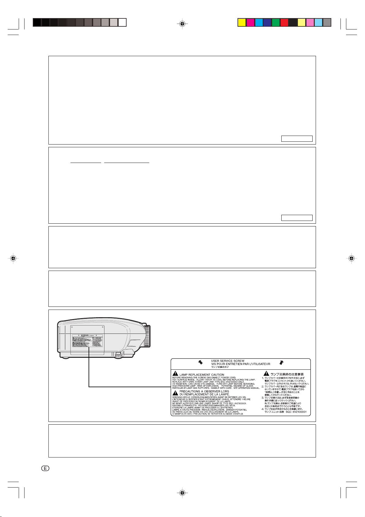
Caution concerning the lamp unit
■ Potential hazard of glass particles if
lamp ruptures. In case of lamp rupture,
contact your nearest Authorized
SharpVision Service Center or Dealer
for replacement.
See “Replacing the Lamp” on page 76.
CAUTION
PRECAUCIÓN
PRÉCAUTION
BQC-XVZ100001
Cautions concerning the setup of the projector
■ For minimal servicing and to maintain high image quality, SHARP recommends that this projector be installed
in an area free from humidity, dust and cigarette smoke.
When the projector is subjected to these environments,
the lens must be cleaned more often. As long as the
projector is regularly cleaned, use in these environments will not reduce the overall operation life of the
unit. Internal cleaning should only be performed by an
Authorized SharpVision Service Center or Dealer.
Do not set up the projector in places exposed to
direct sunlight or bright light.
■ Position the screen so that it is not in direct sunlight or
room light. Light falling directly on the screen washes
out the colors, making viewing difficult. Close the curtains and dim the lights when setting up the screen in a
sunny or bright room.
The projector may safely be tilted to a maximum
angle of 5 degrees.
■ Placement should be within ±5 degrees.
Do not subject the projector to hard impact and/
or vibration.
■ Take care with the lens so as not to hit or damage the
surface of the lens.
Rest your eyes occasionally.
■ Watching the screen for long hours continuously will
make your eyes tired. Be sure to occasionally rest your
eyes.
Avoid locations with high or low temperature.
■ The operating temperature for the projector is from 41°F
to 95°F (+5°C to +35°C).
■ The storage temperature for the projector is from
–4°F to 140°F (–20°C to +60°C).
■ Be sure that the intake vent and the exhaust vent are
not obstructed.
■ If the cooling fan becomes obstructed, a protection circuit will automatically turn off the projector. This does
not indicate a malfunction. Remove the projector power
cord from the wall outlet and wait at least 10 minutes.
Place the projector where the intake and exhaust vents
are not blocked, plug the power cord back in and turn
on the projector. This will return the projector to the
normal operating condition.
Cautions regarding the transportation of the projector
■ When transporting the projector, be sure not to subject
it to hard impact and/or vibration, as this can result in
damage. Take extra caution with the lens. Before moving the projector, be sure to unplug the power cord from
the wall outlet, and disconnect any other cables connected to it.
Other connected equipment
■ When connecting other audio-visual equipment or a
computer to the projector, make the connections AFTER turning off the projector and the equipment to be
connected.
■ Please read the operation manuals of the projector and
the equipment to be connected for instructions on how
to make the connections.
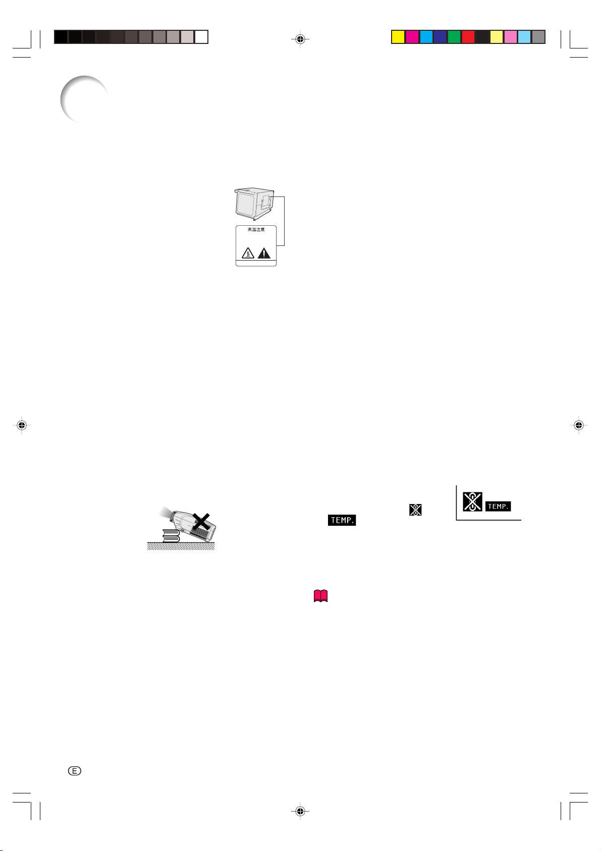
Temperature monitor function
■ If the projector starts to overheat
due to setup problems or blockage
of the air vents, “ ” and
“ ” will blink in the lower left
corner of the picture. If the temperature continues to rise, the lamp will turn off, the
temperature warning indicator on the projector will blink,
and after a 90-second cooling-off period the power will
shut off. Refer to “Maintenance Indicators” on page 74
for details.
Info
• The cooling fan regulates the internal temperature, and
its performance is automatically controlled. The sound
of the fan may change during projector operation due
to changes in the fan speed. This does not indicate
malfunction.
• Do not unplug the power cord during projection or cooling fan operation. This can create damage due to the
rise in internal temperature, as the cooling fan also
stops.
Do not block the intake and exhaust vents.
■ Allow at least 1 foot (30 cm) of space between the exhaust vent and the nearest wall or obstruction.
-8
XV-Z10000#Print#p06_14.p65 02.10.25, 7:25 PM8
How to Access the PDF Operation Manuals of
SharpVision Manager
PDF operation manuals for the “SharpVision Manager” theater projector software provided
are included in the CD-ROM in several languages. To utilize these manuals, you need Adobe
Acrobat Reader installed on your PC (Windows or Macintosh). If you have not installed Acrobat Reader yet, you can install it from the CD-ROM.
To install Acrobat Reader from the CD-ROM
For Windows:
1 Insert the CD-ROM in the CD-ROM drive.
2 Double click the “My Computer” icon.
3 Double click the “CD-ROM” drive.
4 Double click the “ACROBAT” folder.
5 Double click the language (name of the folder)
that you want to view.
6 Double click the installation program and
follow the instructions on the screen.
For other operating systems:
Please download Acrobat Reader from the Internet (http://www.adobe.com).
For other languages:
If you prefer using Acrobat Reader for languages other than those included in the CD-ROM, please
download the appropriate version from the Internet.
For Macintosh:
1 Insert the CD-ROM in the CD-ROM drive.
2 Double click the “CD-ROM” icon.
3 Double click the “ACROBAT” folder.
4 Double click the language (name of the folder)
that you want to view.
5 Double click the installation program and
follow the instructions on the screen.
Introduction
Accessing the PDF Manuals
For Windows:
1 Insert the CD-ROM in the CD-ROM drive.
2 Double click the “My Computer” icon.
3 Double click the “CD-ROM” drive.
4 Double click the “MANUALS” folder.
5 Double click the language (name of the
folder) that you want to view.
6 Double click the “SVM2” pdf file to access the
SharpVision Manager manual.
Note
•If the desired pdf file cannot be opened by double clicking the mouse, start Acrobat Reader first, then
specify the desired file using the “File”, “Open” menu.
•See the “readme.txt” file on the CD-ROM for important information not included in this operation manual.
For Macintosh:
1 Insert the CD-ROM in the CD-ROM drive.
2 Double click the “CD-ROM” icon.
3 Double click the “MANUALS” folder.
4 Double click the language (name of the
folder) that you want to view.
5 Double click the “SVM2” pdf file to access the
SharpVision Manager manual.
XV-Z10000#Print#p06_14.p65 02.10.25, 7:25 PM9
-9

Part Names
Numbers in refer to the main pages in this operation manual where the topic is explained.
Projector (Front and Top View)
Adjustment buttons
For selecting menu items.
For setting items selected
or adjusted on the menu.
For undoing an operation or
(", ', \, |)
ENTER button
UNDO button
returning to the default
settings.
Lens shift dial
Zoom knob
Focus ring
Adjustment foot
Lens cap
27
26
26
25
32
32
37
MENU button
32
For displaying adjustment
and setting screens.
RESIZE button
58
For switching the screen
size (NORMAL,
STRETCH, etc.)
INPUT button
32
For switching input mode
1, 2, 3, 4 or 5.
Power (ON/OFF) buttons
32
For turning the power on
or off.
74
Temperature warning
indicator
When the internal
temperature rises, this
indicator will illuminate
red.
Lamp replacement
32
indicator
Illuminates blue, indicating
normal function. Replace
the lamp when the
indicator illuminates red.
Power indicator
32
Illuminates red, when the
projector is in standby.
When the power is turned
on, this indicator will
illuminate blue.
73
Intake vent
Attaching and removing the lens cap
• Press on the two buttons of the lens cap
and attach it on the lens. Then release
the buttons to lock it in place.
• Press on the two buttons of the lens cap
and remove it from the lens.
-10
XV-Z10000#Print#p06_14.p65 02.10.25, 7:25 PM10
25
Adjustment foot
13
Remote control
sensor
HIGH CONTRAST/
61
HIGH BRIGHTNESS
MODE button
For switching between
“HIGH CONTRAST MODE”
and “HIGH BRIGHTNESS
MODE”.
Air filter/cooling
73
fan (Intake vent)
(on the bottom of
the projector)
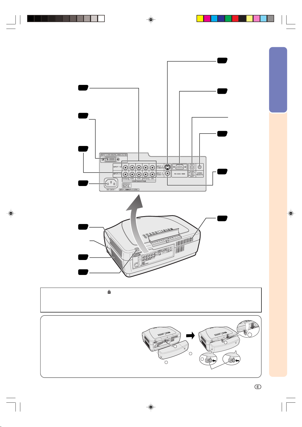
Projector (Rear View)
2
INPUT 3 terminal
17
Terminal for
connecting video
equipment with an
S-video terminal.
Introduction
INPUT 1 terminals
Terminals for
component and
RGB signals
INPUT 5 terminal
Terminal for DVI
digital, computer
RGB, and
COMPONENT
signals.
INPUT 2 terminals
Terminals for
component and RGB
signals
AC socket
Intake vent
18
.
19
RS-232C terminal
23
For controlling
projector using a
computer.
DC 12V OUTPUT
terminal
WIRED REMOTE
24
control input
terminal
18
.
INPUT 4 terminal
17
For connecting
16
video equipment.
Intake vent
73
73
Kensington Security
Standard connector
Exhaust vent
Remote control
sensor
73
13
Using the Kensington Lock
This projector has a Kensington Security Standard connector for use with a Kensington MicroSaver Security
System. Refer to the information that came with the system for instructions on how to use it to secure the
projector.
Using the Terminal Cover
When the projector is used on a desktop, high
mounted or ceiling mounted, attach the terminal
cover (supplied) to hide the connecting cables.
Attaching the Terminal Cover
1 Align with the tab on the projector, push the
two clips attached on the bottom.
2
1
1
1
2
2 Press the tab to attach to the projector.
Attach the clips after removing the rubber cap.
PUSH!
-11
XV-Z10000#Print#p06_14.p65 02.10.25, 7:25 PM11

Part Names
Remote Control (Front View)
For adjusting Keystone Correction
KEYSTONE button
or Vertical Size setting.
ENTER button
For setting items selected or
adjusted on the menu.
36
32
Power (ON/OFF) buttons
32
For turning the power on or off.
MENU button
32
For displaying adjustment and
setting screens.
Adjustment buttons
32
(', ", \, |)
For selecting menu items.
For undoing an operation or
UNDO button
returning to the default settings.
AUTO SYNC button
For automatically adjusting images
when connected to a computer.
RGB/COMP. button
For switching to the respective
input signal type.
37
55
18
Remote Control (Top View)
32
INPUT buttons
For switching to the respective
input modes.
RESIZE button
58
For switching the screen size
(NORMAL, STRETCH, etc.)
PICTURE SETTING button
47
For selecting the picture memory
setting.
Backlight button
For lighting each button,
press this button.
WIRED R/C JACK
24
For controlling the projector by
connecting the remote control to the
projector.
Remote control signal transmitters
-12
XV-Z10000#Print#p06_14.p65 02.10.25, 7:25 PM12
13
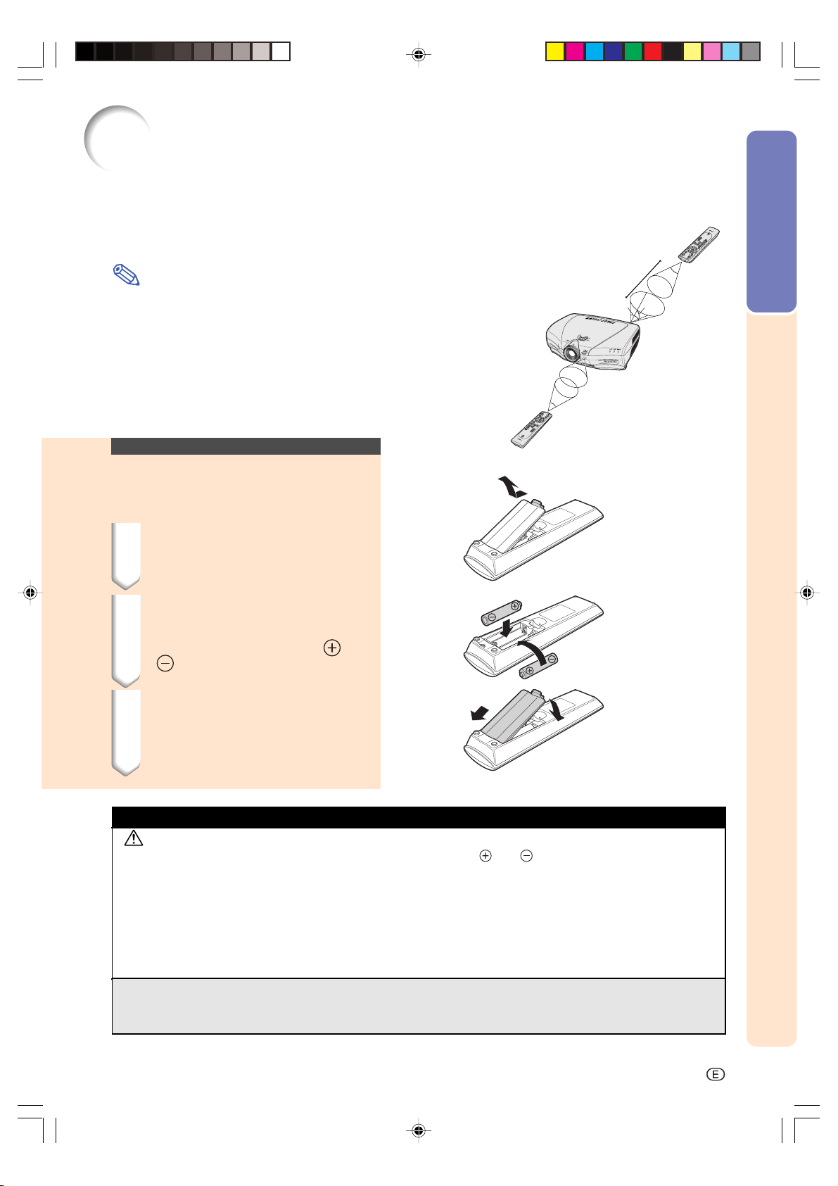
Using the Remote Control
Available Range of the Remote Control
■ The remote control can be used to control the projector
within the ranges shown in the illustration.
Note
•The signal from the remote control can be reflected off a screen
for easy operation. However, the effective distance of the signal
may differ due to the screen material.
Remote control
23'(7 m)
45˚
30˚
30˚
Introduction
When using the remote control:
•Be sure not to drop, expose to moisture or high temperature.
•The remote control may malfunction under a fluorescent lamp.
Under that circumstance, move the projector away from the fluorescent lamp.
Inserting the Batteries
The batteries (two “AA” size) are included in
the package.
1 Pull down the tab on the cover
and remove the cover towards
the direction of the arrow.
2 Insert the included batteries.
•Insert the batteries making sure the
polarities correctly match the
marks inside the battery
compartment.
and
3 Insert the lower tab of the
cover into the opening, and
lower the cover until it clicks
in place.
45˚
30˚
Remote control
Incorrect use of the batteries may cause them to leak or explode. Please follow the precautions below.
Caution
•Insert the batteries making sure the polarities correctly match the and marks inside the battery compart-
ment.
•Batteries of different types have different properties, therefore do not mix batteries of different types.
•Do not mix new and old batteries.
This may shorten the life of new batteries or may cause old batteries to leak.
•Remove the batteries from the remote control once they have run out, as leaving them can cause them to leak.
Battery fluid from leaked batteries is harmful to your skin, therefore be sure to first wipe them and then remove
them using a cloth.
•The batteries included with this projector may exhaust over a short period, depending on how they are kept.
Be sure to replace them as soon as possible with new batteries when they have run out.
•Remove the batteries from the remote control if you will not be using the remote control for a long time.
XV-Z10000#Print#p06_14.p65 02.10.25, 8:40 PM13
-13
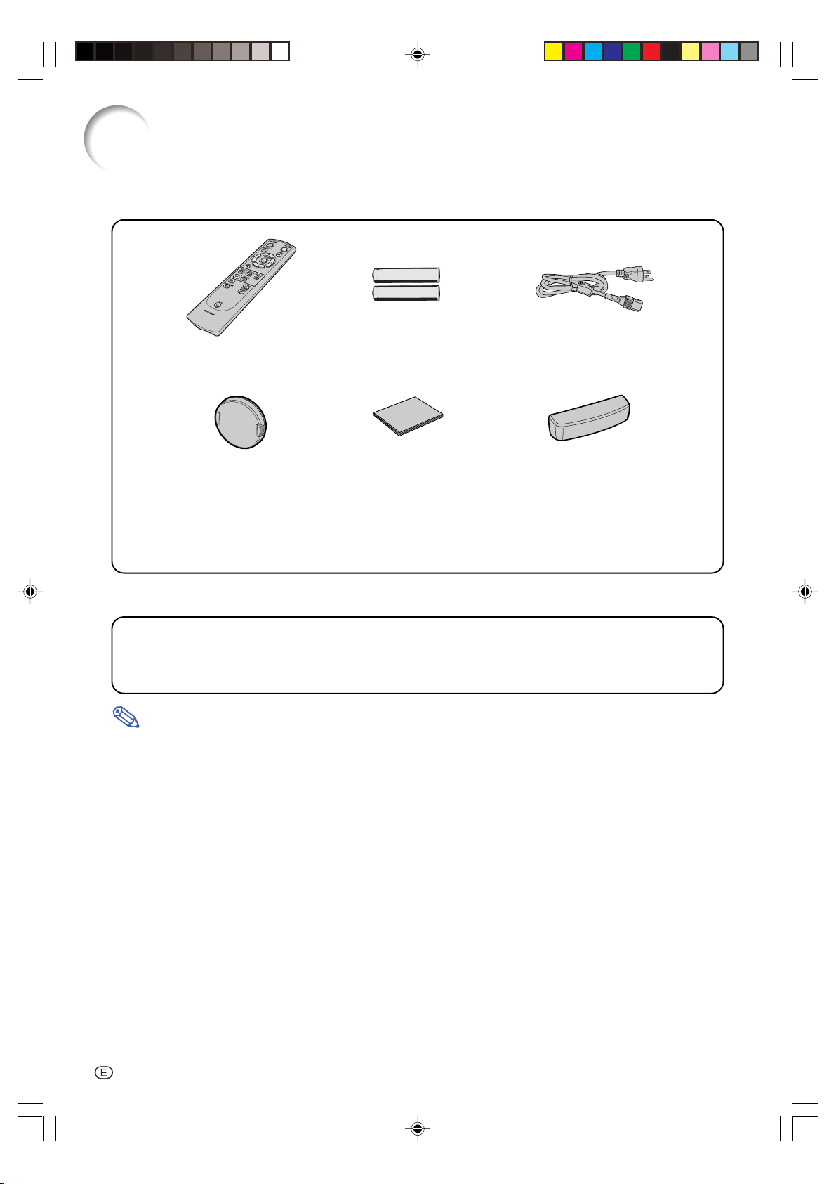
Accessories
Supplied accessories
Remote control
RRMCGA128WJSA
Lens cap (attached)
PCAPH01056CESA
Two “AA” size batteries
CD-ROM
(SharpVision Manager)
UDSKAA019WJZZ
Optional accessories
DVI to 15-pin D-sub adaptor AN-A1DV
RS-232C cable (32'10'' (10.0m)) AN-C10RS
3 RCA to 15-pin D-sub cable (9'10'' (3.0m)) AN-C3CP
DVI cable (9'10'' (3.0m)) AN-C3DV
• Some of the cables may not be available depending on the region. Please check with your nearest
Note
Authorized SharpVision Service Center or Dealer.
Power cord
CACCDA010DE01
Terminal cover
CCOVA1985CE02
Operation manual (this manual)
TINS-A440WJZZ
SharpVision Manager operation manual
TINS-A452WJZZ
-14
XV-Z10000#Print#p06_14.p65 02.10.25, 7:25 PM14
Connections and Setup
Connections and Setup
XV-Z10000#Print#p15_16.p65 02.10.25, 7:25 PM15

Connecting the Projector to Other Devices
Before Connecting
Note
•Before connecting, be sure to turn off both the projector and the devices to be connected. After making all
connections, turn on the projector and then the other devices.
When connecting a computer, be sure that it is the last device to be turned on after all the connections are
made.
•Be sure to read the operation manuals of the devices to be connected before making connections.
This projector can be connected to:
Video equipment:
■ A VCR, Laser disc player or other video equipment (See page 17.)
■ A DVD player or DTV* decoder (See page 18.)
*DTV is the umbrella term used to describe the new digital television system in the United States.
A computer using:
■ DVI to D-sub 15-Pin cable (See page 21.)
■ A DVI cable (See page 22.)
■ An RS-232C cable (AN-C10RS) (sold separately) (See page 23.)
Connecting the Power
Cord
Supplied
accessory
Plug in the supplied power cord into
the AC socket on the rear of the projector.
Power cord
-16
-16
XV-Z10000#Print#p15_16.p65 02.10.25, 7:25 PM16
Connecting the Projector to Other Devices
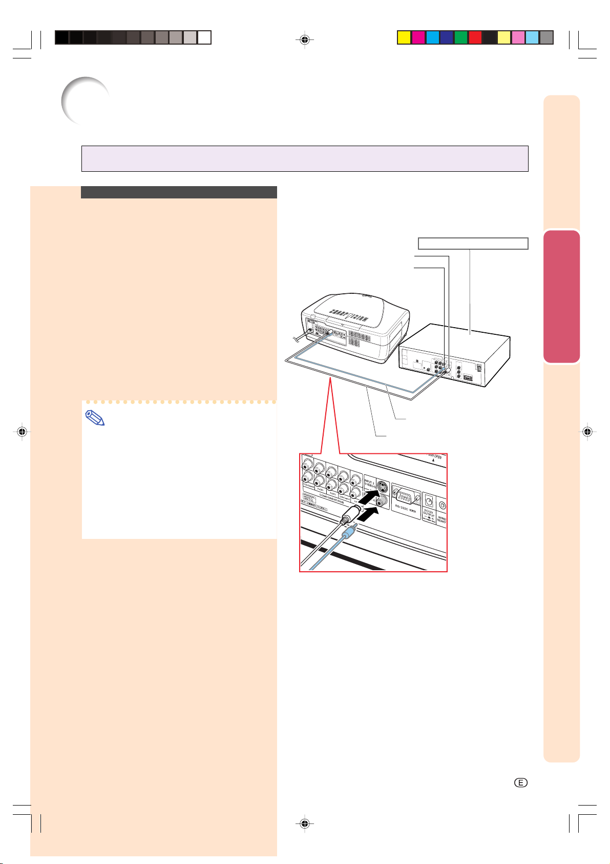
Connecting to Video Equipment
Connecting to Video
Equipment Using an
S-video or a Composite
Video Cable
Using an S-video or a composite video cable,
a VCR, laser disc player or other video equipment can be connected to INPUT 3 and INPUT
4 input terminals.
Connect the projector to the video
equipment using an S-video cable
or a composite video cable (both
commercially available).
To S-video output terminal
Connections and Setup
VCR or other video equipment
To video output terminal
Note
•The INPUT 3 (S-VIDEO) terminal uses a
video signal system in which the picture
is separated into color and luminance signals to realize a higher-quality image. To
view a higher-quality image, use a commercially available S-video cable to connect the INPUT 3 terminal on the projector and the S-video output terminal on the
video equipment.
Composite video cable
(commercially available)
S-video cable (commercially available)
XV-Z10000#Print#p17_20.p65 02.10.25, 7:26 PM17
-17
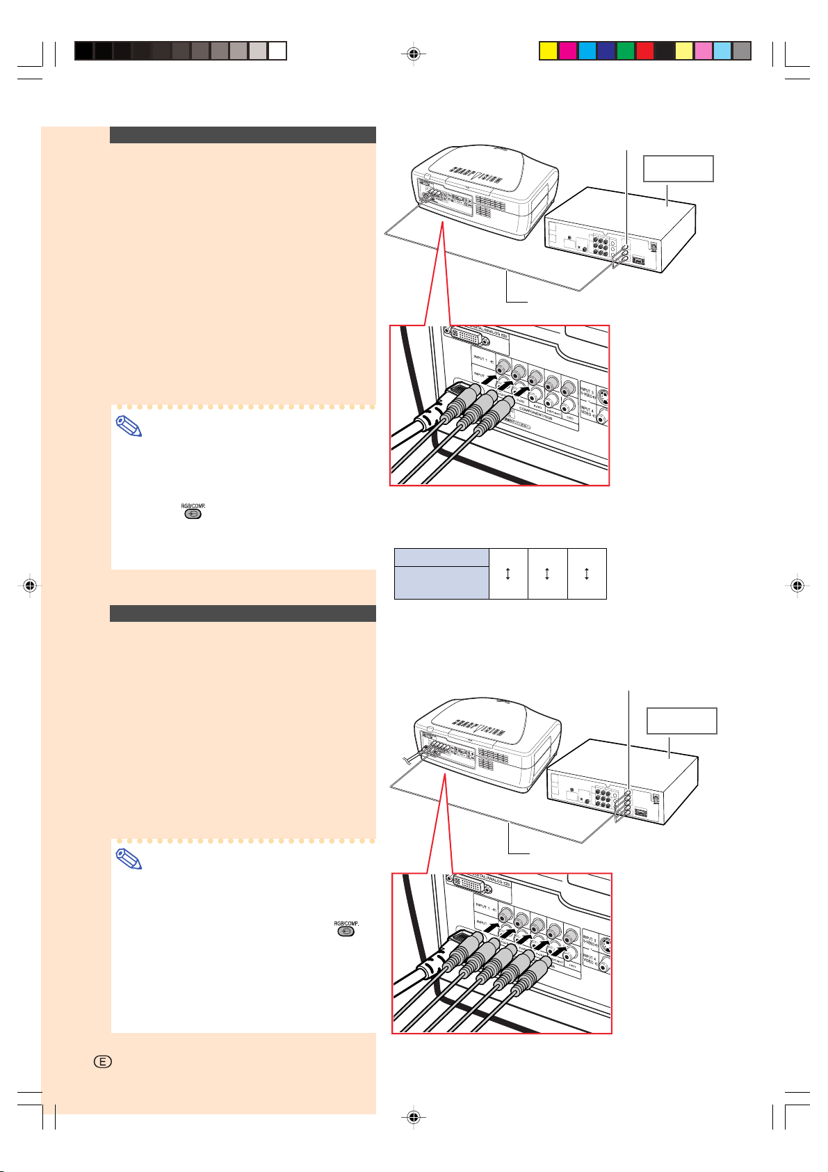
Connecting to
Component Video Equipment
Using a Component Cable
(INPUT 1 or 2)
Use a component cable when connecting to the
INPUT 1 or 2 terminal, component video equipment such as DVD players and DTV* decoders.
*
DTV is the umbrella term used to describe the
new digital television system in the United States.
Connect the projector to the component video equipment using the
component cable.
Note
•When connecting the projector to the
video equipment in this way, select “Component” for “Signal Type” in the “Options”
menu, or select the Component mode by
pressing
page 64.
•Set the “Resolution” of “Special Modes”
to “480P” during input of a 525P signal.
on the remote control. See
The component jack for a DVD and so forth may be indicated with Y, C
shown below at this time.
Projector
DVD player or
DTV decoder
To analog component
output terminal
DVD player or
DTV* decoder
Component cable
(commercially available)
B or CR. Connect each jack in the manner
Y
PBCBPR
Y
CR
Connecting to RGB Video
Equipment Using a 5RCA
RGB Cable (INPUT 1 or 2)
Use a 5RCA RGB cable when connecting to
the INPUT 1 or 2 terminal, RGB video equipment such as DVD players and DTV* decoders.
Connect the projector to the RGB
video equipment using the 5RCA
RGB cable.
Note
•When connecting the projector to the
video equipment in this way, select “RGB”
for “Signal Type” in the “Options” menu,
or select the RGB mode by pressing
on the remote control. See page 64.
•The (HD/C sync) and (VD) terminals may
be used depending on the specifications
of the DTV decoder connected to this projector. Please refer to the operation
manual of the DTV decoder for details.
To analog RGB
output terminal
DVD player or
DTV* decoder
5RCA RGB cable
(Commercially available)
-18
XV-Z10000#Print#p17_20.p65 02.10.25, 7:26 PM18
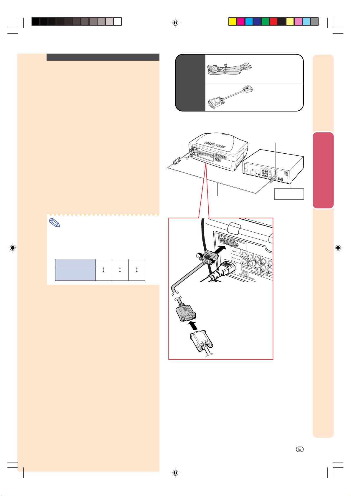
Connecting to Component Video Equipment
Using a 3 RCA to 15-pin
D-Sub Cable Using the
DVI to 15-pin D-Sub
adaptor (INPUT 5)
Use a 3 RCA to 15-pin D-Sub cable using the
DVI to 15-pin D-Sub adaptor when connecting to the INPUT 5 terminal, component video
equipment such as DVD players and DTV*
decoders.
*
DTV is the umbrella term used to describe the
new digital television system in the United States.
Connect the projector to the video
equipment using a 3 RCA to 15-pin
D-Sub cable using the DVI to 15-pin
D-Sub adaptor.
Note
•The component jack for a DVD and so
forth may be indicated with Y, C
Connect each jack in the manner shown
below at this time.
B or CR.
Optional
accessories
DVI to 15-pin
D-sub adaptor
(sold
separately)
3 RCA to 15-pin
D-sub cable
(sold separately)
3 RCA to 15-pin
D-sub cable
Type: AN-C3CP
(9'10" (3.0 m))
DVI to 15-pin
D-sub adaptor
Model: AN-A1DV
(7.9" (20 cm))
To analog component
output terminal
DVD player or
DTV* decoder
Connections and Setup
Projector
DVD player or
DTV decoder
Y
Y
PBCBPR
CR
XV-Z10000#Print#p17_20.p65 02.10.25, 7:26 PM19
-19
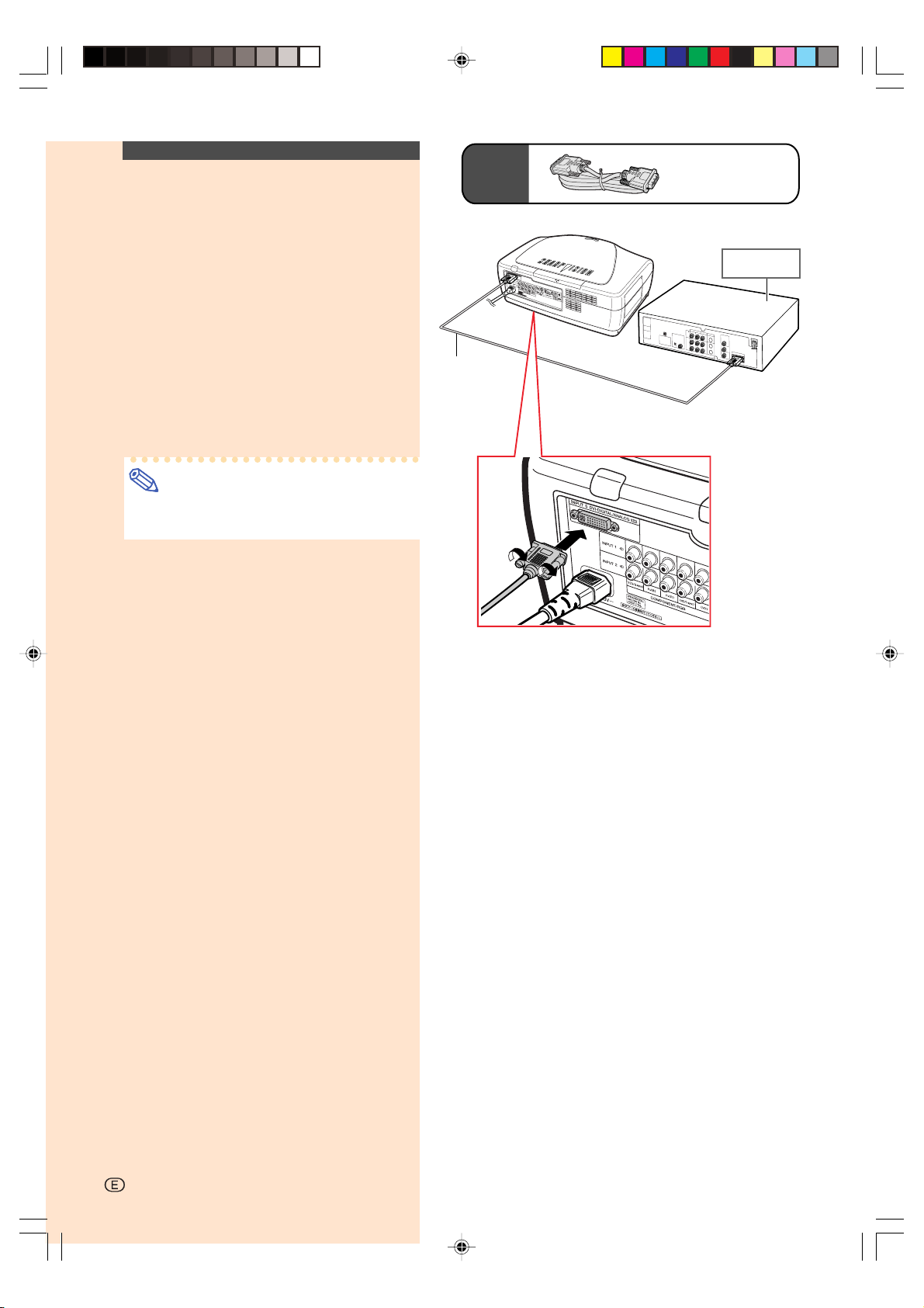
Connecting to Video
Equipment with the DVI
Output Termianl Using
the DVI Cable
Use the DVI cable when connecting to the INPUT 5 terminal, video equipment with the DVI
output terminal such as DVD players and DTV*
decoders.
Optional
accessory
DVI cable
Type:AN-C3DV
(9'10'' (3.0m))
DVD player or
DTV* decoder
*
DTV is the umbrella term used to describe the
new digital television system in the United States.
Connect the projector to the video
equipment using the DVI cable.
Note
•Select the input signal type of the video
equipment. See page 64.
DVI cable
(sold separately)
-20
XV-Z10000#Print#p17_20.p65 02.10.25, 7:26 PM20
Connecting the Projector to Other Devices
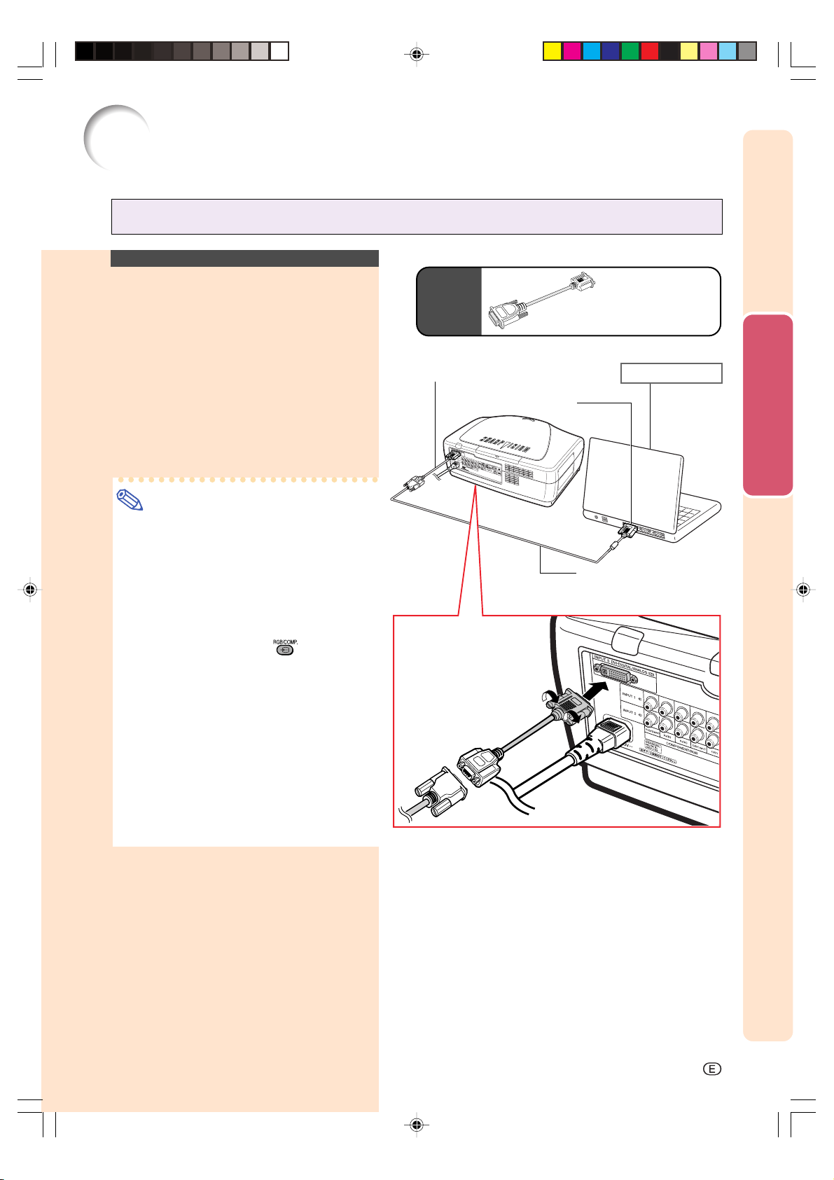
Connecting the Projector to a Computer
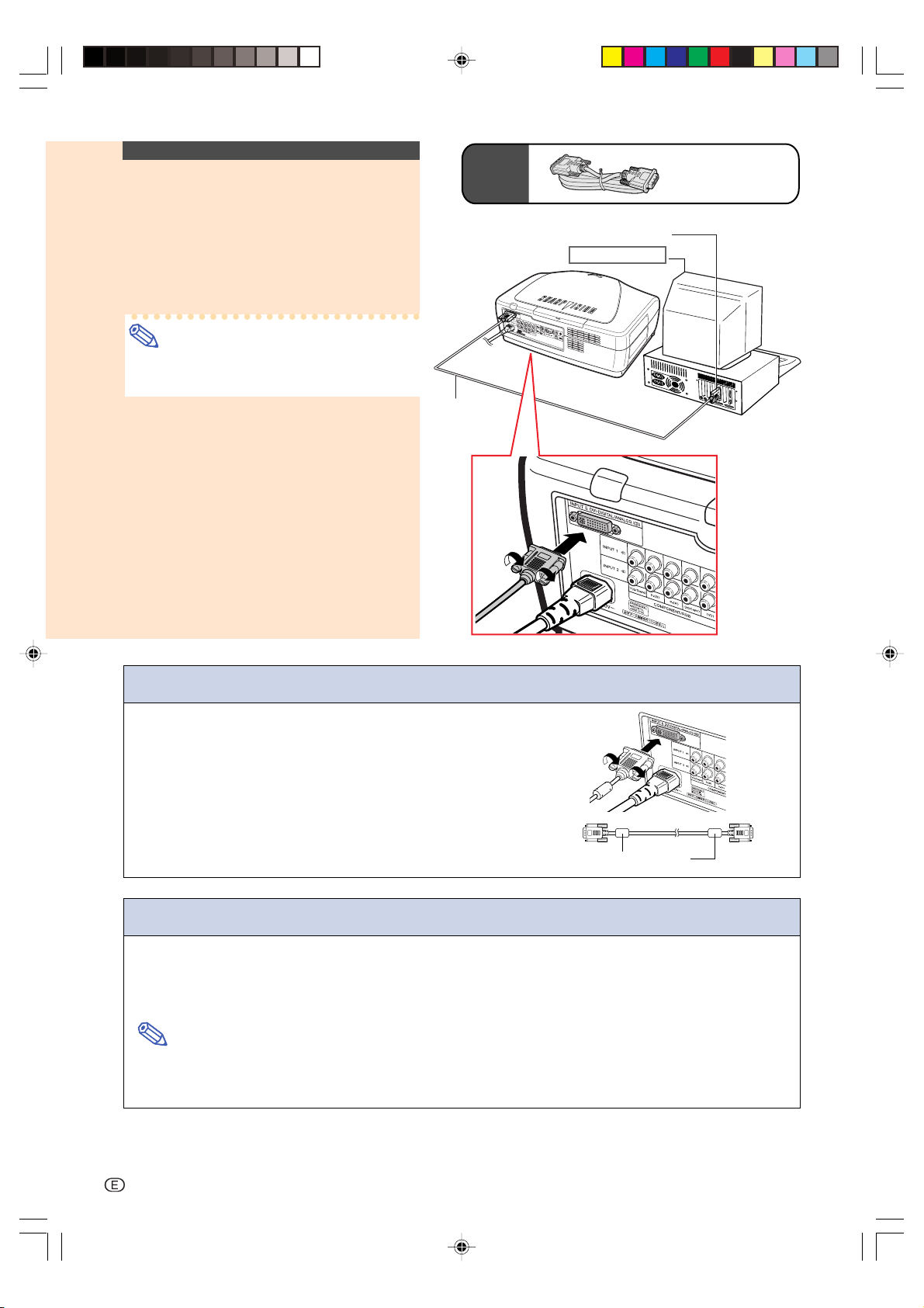
Connecting to a Computer
Using the the DVI to
15-pin D-sub Adaptor and
the RGB Cable
Connect the projector to the computer using the DVI to 15-pin D-sub
adaptor and the RGB cable.
•Secure the connectors by tightening the
thumbscrews.
Note
•See page 84 “Computer Compatibility
Chart” for a list of computer signals compatible with the projector. Use with computer signals other than those listed may
cause some of the functions not to work.
•When connecting the projector to a com-
puter in this way, select “RGB” for “Signal
Type” in the “Options” menu, or select the
RGB mode by pressing
mote control. See page 64.
•A Macintosh adaptor may be required for
use with some Macintosh computers. Contact your nearest Authorized SharpVision
Service Center or Dealer.
•Depending on the computer you are us-
ing, an image may not be projected unless the signal output setting of the computer is switched to the external output.
Refer to the computer operation manual
for switching the computer signal output
settings.
on the re-
Optional
accessory
DVI to 15-pin D-sub adaptor
(sold separately)
To RGB output terminal
DVI to 15-pin D-sub adaptor
Type: AN-A1DV (7.9" (20cm))
Notebook computer
RGB Cable (commercially
available)
Connections and Setup
XV-Z10000#Print#p21_22.p65 02.10.25, 7:27 PM21
-21
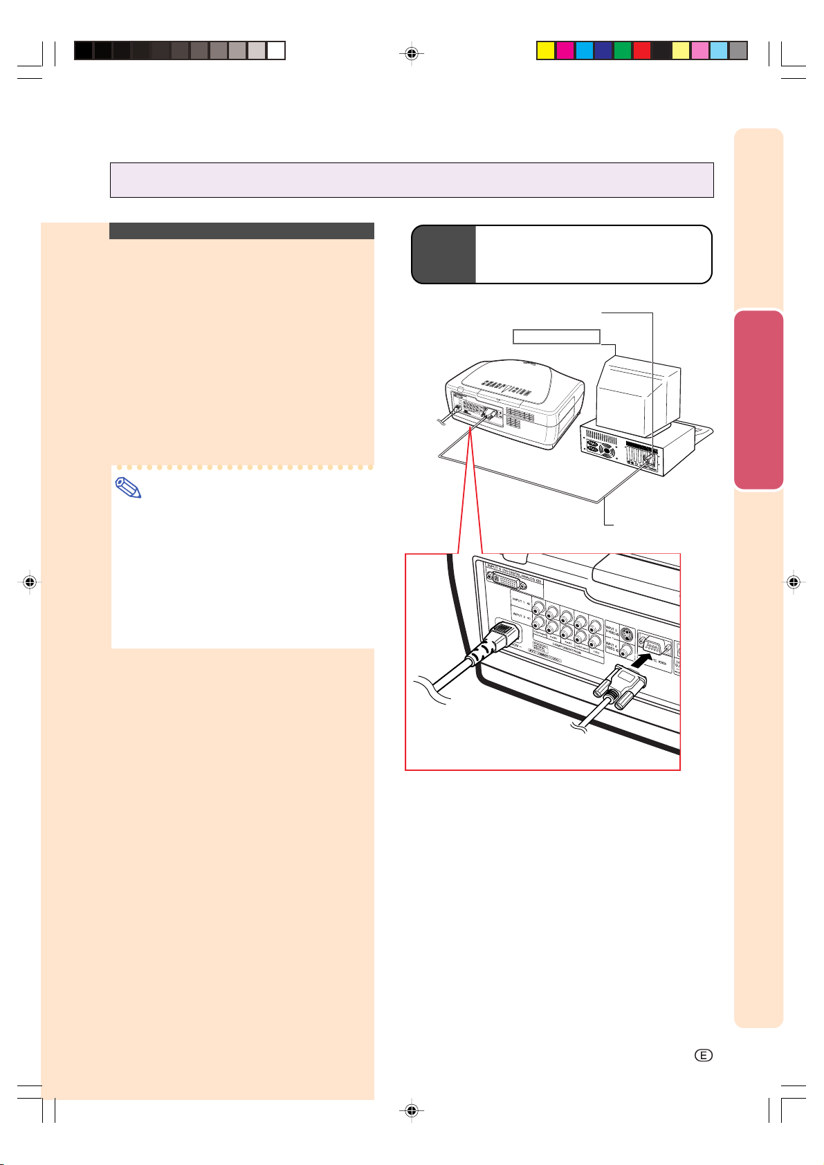
Connecting to a Computer Using a DVI
Cable (Sold Separately)
Connect the projector to the computer using the DVI cable.
Note
•Select the input signal type of the video
equipment. See page 64.
Optional
accessory
DVI cable
(sold separately)
DVI cable
Type:AN-C3DV
(9'10'' (3.0m))
To DVI Digital output terminal
Desktop computer
Connecting the thumbscrew cables
■ Connect the thumbscrew cable making sure that it fits correctly into the terminal. Then, firmly secure the connectors by tightening the screws on both sides of the plug.
Do not remove the ferrite core attached to the RGB cable.
■
Ferrite core
“Plug and Play” function
■ This projector is compatible with VESA-standard DDC 1/DDC 2B. The projector and a VESA DDC
compatible computer will communicate their setting requirements, allowing for quick and easy setup.
■ Before using the “Plug and Play” function, be sure to turn on the projector first and the connected
computer last.
Note
•The DDC “Plug and Play” function of this projector operates only when used in conjunction with a VESA
DDC compatible computer.
-22
XV-Z10000#Print#p21_22.p65 02.10.25, 7:27 PM22
Controlling the Projector by a Computer
Controlling the
Projecor Using an RS232C Cable
When the RS-232C terminal on the projector
is connected to a computer with an RS-232C
cable (null modem, cross type, sold separately), the computer can be used to control
the projector and check the status of the projector. See page 80 for details.
Connect the projector to the computer using an RS-232C cable.
Note
•Do not connect or disconnect an RS-232C
cable to or from the computer while it is
on. This may damage your computer.
•The RS-232C function may not operate if
your computer terminal is not correctly set
up. Refer to the operation manual of the
computer for details.
•See page 79 for connection of an RS-
232C cable.
Optional
cable
RS-232C cable
Type: AN-C10RS (32'10'' (10.0m))
RS-232C terminal
Desktop computer
RS-232C cable
(sold separately)
Connections and Setup
XV-Z10000#Print#p23_24.p65 02.10.25, 7:27 PM23
-23
Connecting the Projector to Other Devices
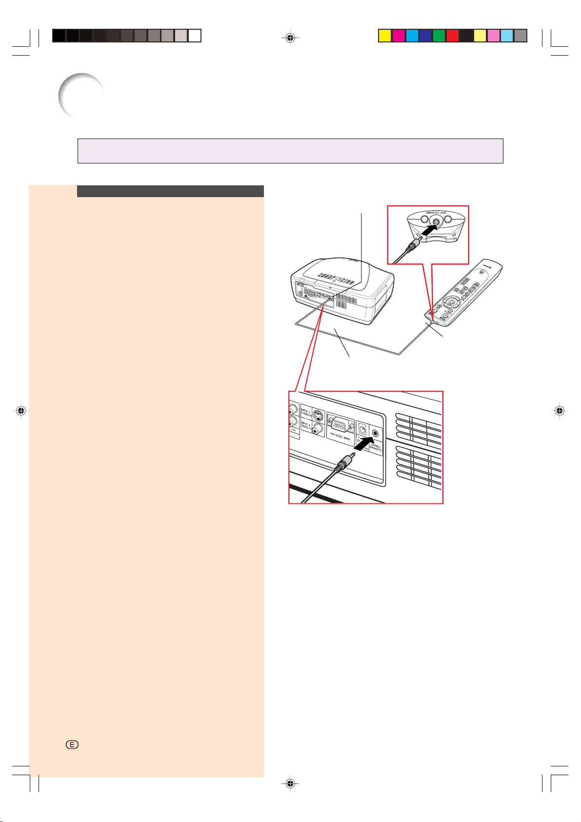
Using as a Wired Remote Control
Connecting the Remote
Control to the Projector
When the remote control cannot be used due
to the range or positioning of the projector
(rear projection, etc.), connect a ø3.5 mm
minijack cable (commercially available or
available as Sharp service part QCNW4870CEZZ) from the WIRED R/C JACK on the
top of the remote control to the WIRED REMOTE control input terminal.
WIRED REMOTE control input
terminal
To WIRED R/C JACK
ø3.5 mm minijack cable
(commercially available or available as
Sharp service part QCNW-4870CEZZ)
-24
-24
XV-Z10000#Print#p23_24.p65 02.10.25, 7:27 PM24
Setup
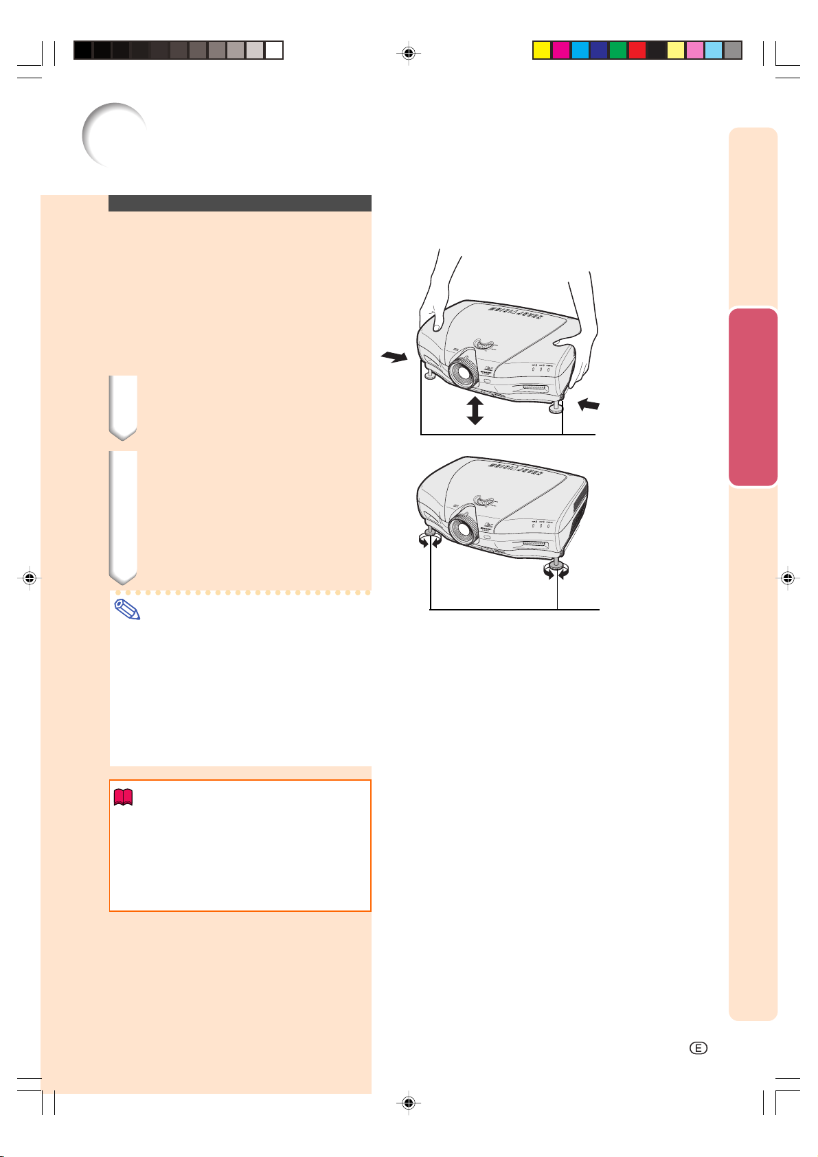
Using the Adjustment
Feet
The height of the projector can be adjusted
using the adjustment feet when the surface
the projector is placed on is uneven or when
the screen is slanted.
The projection of the image can be made
higher by adjusting the projector when it is in
a location lower than the screen.
1 Press the foot releases and lift
the projector to the desired
angle.
2 Remove your hands from the
foot releases. Once the adjustment feet have locked in position, release the projector.
•If the screen is at an angle, the ad-
justment feet can be used to adjust the
angle of the image.
Connections and Setup
Foot releases
Note
•The projector is adjustable up to approxi-
mately 5 degrees from the standard position.
•When the height of the projector is ad-
justed, the image may become distorted
(keystoned), depending on the relative
positions of the projector and the screen.
See page 36 for details on the keystone
correction.
Info
•Do not hold the lens when lifting or lower-
ing the projector.
•When lowering the projector, be careful
not to get your finger caught in the area
between the adjustment foot and the
projector.
Adjustment feet
XV-Z10000#Print#p25_30.p65 02.10.25, 7:28 PM25
-25

Setup
Adjusting the Lens
The image is focused and adjusted to the
desired size using the focus ring or zoom
knob on the projector.
1 Zooming is adjusted by mov-
ing the zoom knob.
Focus ring
Zoom in
Zoom Knob
Zoom
Zoom knob
out
2 The focus is adjusted by rotat-
ing the focus ring.
Focus ring
-26
XV-Z10000#Print#p25_30.p65 02.10.25, 7:28 PM26
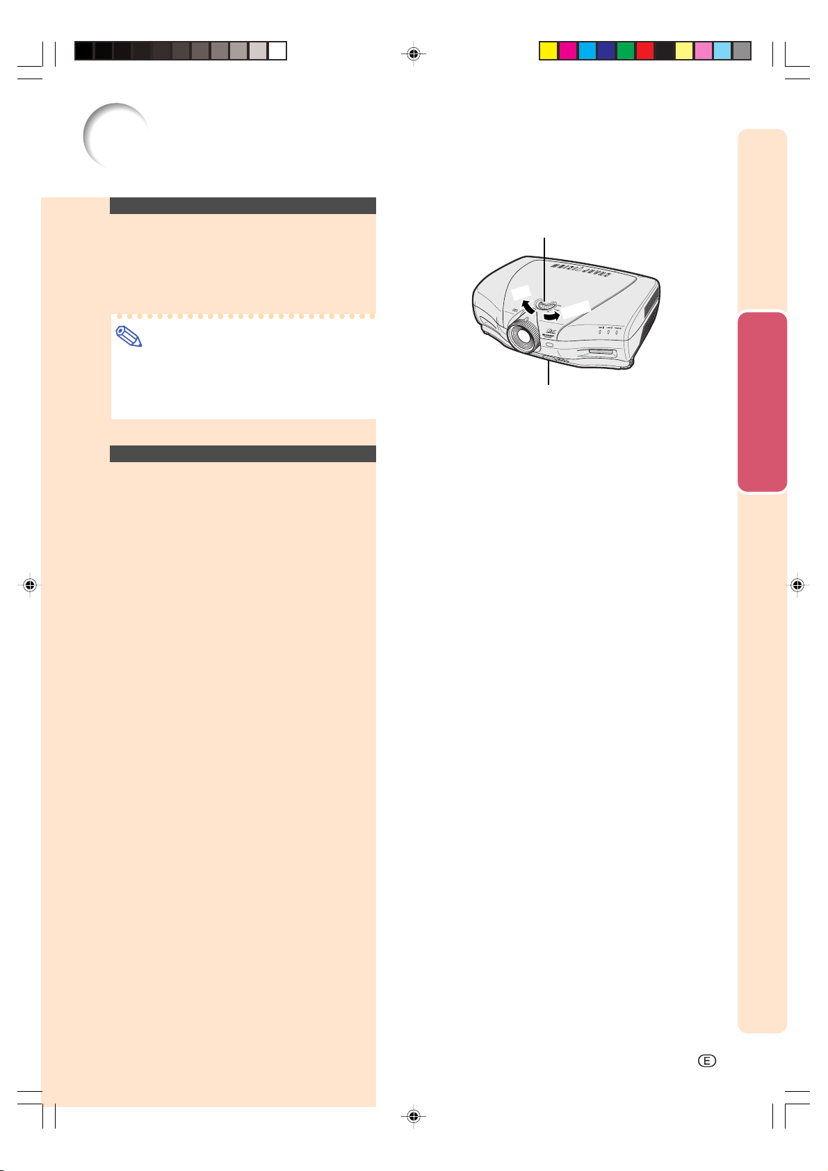
Setup
Using the Lens Shift
The height of the projected image can be adjusted within the shift range of the lens by
rotating the lens shift dial on the top of the
projector.
Note
•Do not forcibly turn the lens shift dial be-
yond the range of the upper limit and lower
limit positions. This may cause the projector to malfunction.
Selecting the HIGH
CONTRAST/ HIGH
BRIGHTNESS MODE
Pressing the HIGH CONTRAST/HIGH BRIGHTNESS MODE button switches between the
contrast emphasis mode and brightness emphasis mode. See page 61 for details.
Lens shift dial
p
U
Down
HIGH CONTRAST/
HIGH BRIGHTNESS
MODE button
Connections and Setup
XV-Z10000#Print#p25_30.p65 02.10.25, 7:28 PM27
-27
 Loading...