

Page 1
XV-DW100U
SERVICE MANUAL
SY9U3XVDW100U
LCD PROJECTOR
MODEL
In the interests of user-safety (Required by safety regulations in some countries) the set should be restored
to its original condition and only parts identical to those specified should be used.
XV-DW100U
CONTENTS
Page Page
• SPECIFICATIONS.............................................. 2
• IMPORTANT SERVICE SAFETY NOTES.......... 3
• NOTE TO SERVICE PERSONNEL.................... 4
• OPERATION MANUAL ...................................... 7
• REMOVING OF MAJOR PARTS...................... 12
• RESETTING THE TOTAL LAMP TIMER .......... 17
• THE OPTICAL UNIT OUTLINE........................ 18
• CONVERGENCE AND
FOCUS ADJUSTMENT .................................. 19
• ELECTRICAL ADJUSTMENT.......................... 25
• ADJUSTING THE PC INTERFACE.................. 33
• TROUBLE SHOOTING TABLE ........................ 34
• CHASSIS LAYOUT........................................... 50
• BLOCK DIAGRAM ........................................... 52
• OVERALL WIRING DIAGRAM......................... 54
• DESCRIPTION OF SCHEMATIC DIAGRAM ... 56
• WAVEFORMS .................................................. 57
• SCHEMATIC DIAGRAM................................... 58
• PRINTED WIRING BOARD ASSEMBLIES.... 108
• PARTS LIST
Ë
ELECTRICAL PARTS............................... 117
Ë
CABINET AND MECHANICAL PARTS .... 145
Ë
ACCESSORIES PARTS ........................... 150
Ë
PACKING PARTS ..................................... 150
• PACKING OF THE SET ................................. 151
SHARP CORPORATION
This document has been published to be used for
after sales service only.
The contents are subject to change without notice.
1
Page 2
XV-DW100U
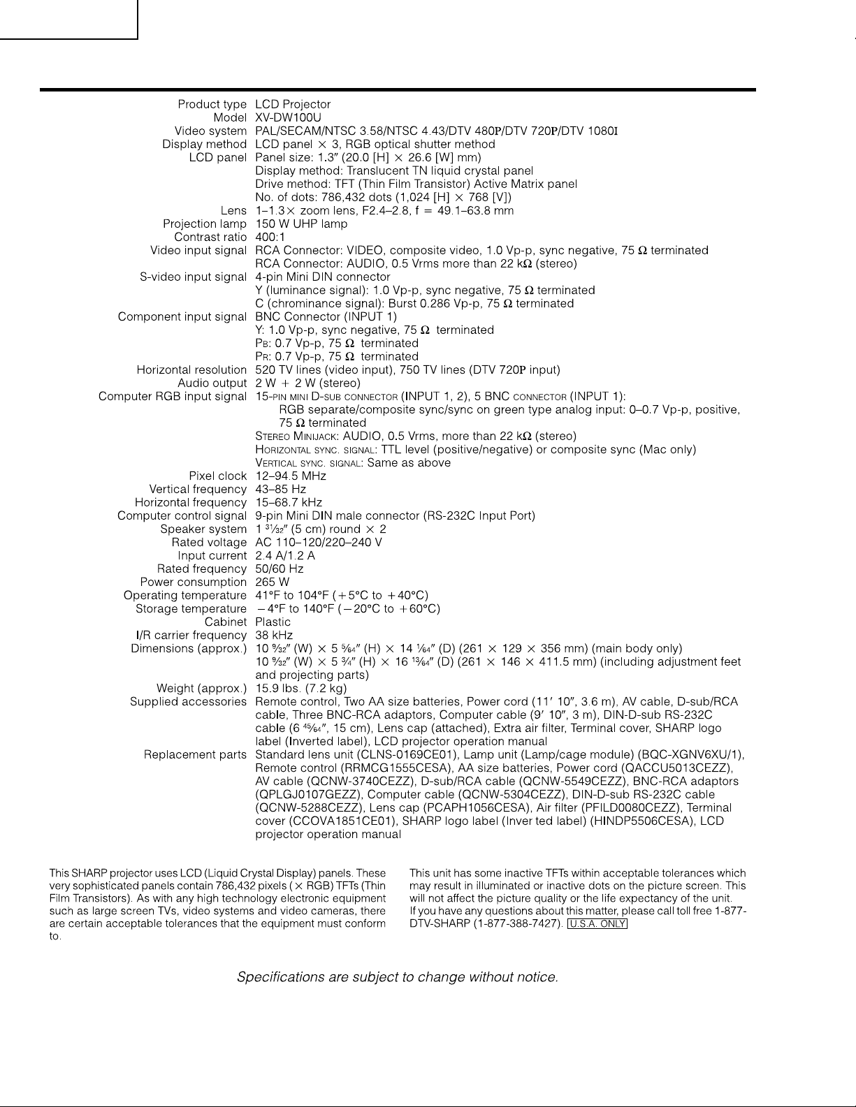
Specifications
2
Page 3
XV-DW100U
2
2
IMPORTANT SERVICE SAFETY NOTES
Ë Service work should be performed only by qualified service technicians who are
thoroughly familiar with all safety checks and servicing guidelines as follows:
WARNING
1. For continued safety, no modification of any circuit
should be attempted.
2. Disconnect AC power before servicing.
BEFORE RETURNING THE PROJECTOR:
(Fire & Shock Hazard)
Before returning the projector to the user, perform
the following safety checks:
1. Inspect lead wires are not pinched between the
chassis and other metal parts of the projector.
2. Inspect all protective devices such as non-metallic
control knobs, insulating materials, cabinet backs,
adjustment and compartment covers or shields,
isolation resistor-capacity networks, mechanical
insulators, etc.
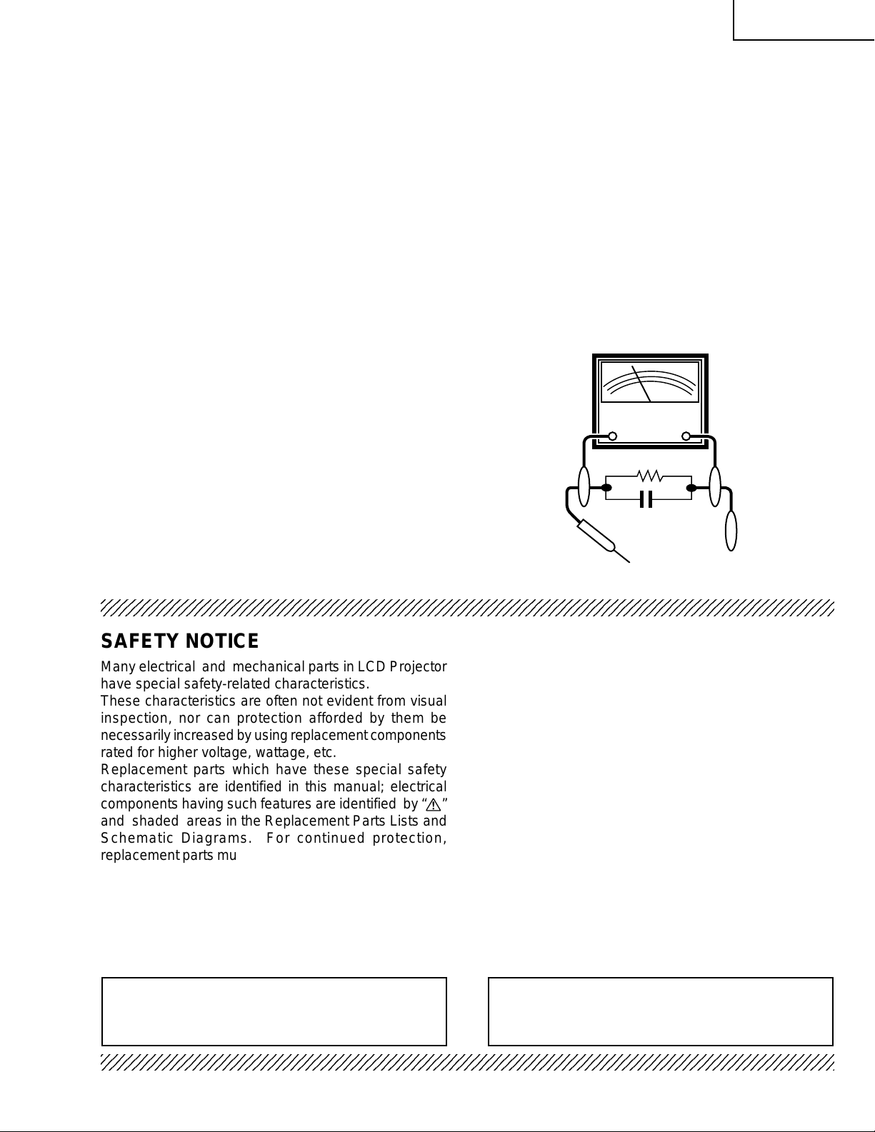
3. To be sure that no shock hazard exists, check for
current leakage in the following manner:
» Plug the AC cord directly into a 120-volt AC outlet,
(Do not use an isolation transformer for this test).
» Using two clip leads, connect a 1.5k ohm, 10 watt
resistor paralleled by a 0.15µF capacitor in parallel
between all exposed metal cabinet parts and earth
ground.
» Use an AC voltmeter with sensitivity of 5000 ohm per
volt., or higher , sensitivity to measure the AC voltage
drop across the resistor (See Diagram).
» All checks must be repeated with the AC plug
connection reversed. (If necessary, a non-polarized
adapter plug must be used only for the purpose of
completing these checks.)
Any reading of 0.3 volts RMS (this corresponds to
0.2 milliamp. A C.) or more is e xcessive and indicates
a potential shock hazard which must be corrected
before returning the unit to the owner.
AC
VOLTMETER
1.5k ohm (10W)
0.15µF
TEST PROBE
TO EXPOSED
METAL PARTS
CONNECT TO KNOWN
EARTH GROUND
234567890123456789012345678901212345678901234567890123456789012123456789012345678901234567890121
SAFETY NOTICE
Many electrical and mechanical parts in LCD Projector
have special safety-related characteristics.
These characteristics are often not evident from visual
inspection, nor can protection afforded by them be
necessarily increased by using replacement components
rated for higher voltage, wattage, etc.
Replacement parts which have these special safety
characteristics are identified in this manual; electrical
components having such features are identified by “å”
and shaded areas in the Replacement Parts Lists and
Schematic Diagrams. For continued protection,
replacement parts must be identical to those used in the
original circuit. The use of a substitute replacement parts
which do not have the same safety characteristics as
the factory recommended replacement parts shown in
this service manual, may create shock, fire or other
hazards.
AVIS POUR LA SECURITE
De nombreuses pièces, électriques et mécaniques, dans
les projecteur à LCD présentent des caractéristiques
spéciales relatives à la sécurité, qui ne sont souvent
pas évidentes à vue.
Le degré de protection ne peut pas être nécessairement
augmentée en utilisant des pièces de remplacement
étalonnées pour haute tension, puissance, etc.
Les pièces de remplacement qui présentent ces
caractéristiques sont identifiées dans ce manuel;
les pièces électriques qui présentent ces particularités
sont identifiées par la marque “å” et hachurées dans la
liste des pièces de remplacement et les diagrammes
schématiques. Pour assurer la protection, ces pièces
doivent être identiques à celles utilisées dans le circuit
d’origine. L’utilisation de pièces qui n’ont pas les mêmes
caractéristiques que les pièces recommandées par
l’usine, indiquées dans ce manuel, peut provoquer des
électrocutions, incendies ou autres accidents.
WARNING: The bimetallic component has the primary
conductive side exposed. Be very careful in
handling this component when the power is on.
234567890123456789012345678901212345678901234567890123456789012123456789012345678901234567890121
AVERTISSEMENT:La composante bimétallique dispose du
conducteur primaire dénudé. Faire
attention lors de la manipulation de cette
composante sous tension.
3
Page 4
XV-DW100U
NOTE TO SERVICE
PERSONNEL
UV-RADIATION PRECAUTION
The light source, metal halide lamp, in the LCD
projector emits small amounts of UV-Radiation.
AVOID DIRECT EYE AND SKIN EXPOSURE.
To ensure safety please adhere to the following:
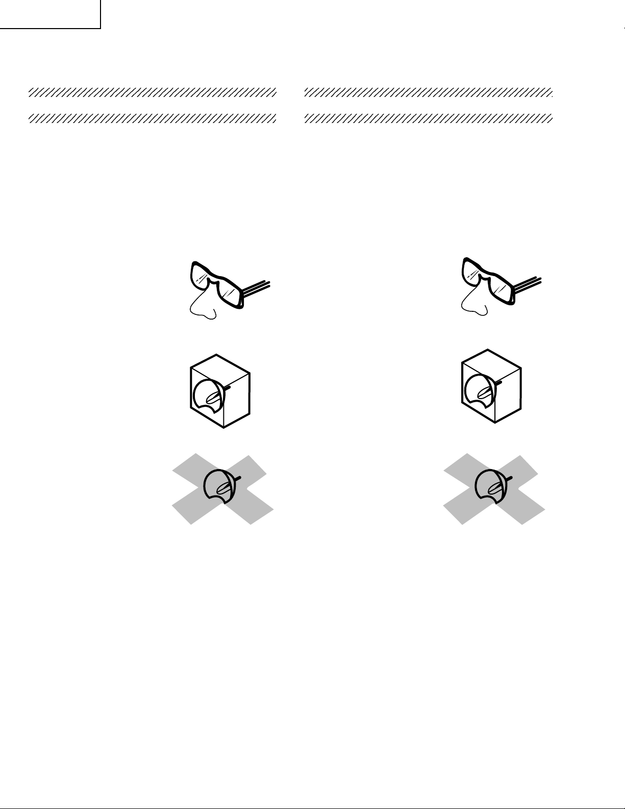
1. Be sure to wear sun-glasses when servicing the
projector with the lamp
turned “on” and the top
enclosure removed.
2. Do not operate the lamp outside of the lamp housing.
NOTE POUR LE PERSONNEL
D’ENTRETIEN
PRECAUTION POUR LES RADIATIONS UV
La source de lumière, la lampe métal halide, dans le
projecteur LCD émet de petites quantités de
radiation UV.
EVITEZ TOUTE EXPOSITION DIRECTE
DES YEUX ET DE LA PEAU.
Pour votre sécurité, nous vous prions de respecter
les points suivants:
1. Toujours porter des lunettes de soleil lors d’un
entretien du projecteur
avec la lampe allumée
et le haut du coffret retiré.
2. Ne pas faire fonctionner la lampe à l’extérieur du
boîtier de lampe.
3. Do not operate for more than 2 hours with the
enclosure removed.
UV-Radiation and Medium Pressure
Lamp Precautions
1. Be sure to disconnect the AC plug when replacing
the lamp.
2. Allow one hour for the unit to cool down before
servicing.
3. Replace only with same type lamp. Type
CLMPF0056DE01 or BQC-XGNV6XU/1 rated 65V/
150W.
4. The lamp emits small amounts of UV-Radiation, a void
direct-eye contact.
5. The medium pressure lamp involves a risk of
explosion. Be sure to follow installation instructions
described below and handle the lamp with care.
3. Ne pas faire fonctionner plus de 2 heures avec le
coffret retiré.
Précautions pour les radiations UV
et la lampe moyenne pression
1. Toujours débrancher la fiche AC lors du
remplacement de la lampe.
2. Laisser l’unité refroidir pendant une heure avant de
procéder à l’entretien.
3. Ne remplacer qu’avec une lampe du même type.
Type CLMPF0056DE01 or BQC-XGNV6XU/1,
caractéristique 65V/150W.
4. La lampe émet de petites quantités de radiation UVéviter tout contact direct avec les yeux.
5. La lampe moyenne pression implique un risque
d’explosion. Toujours suivre les instructions
d’installation décrites ci-dessous et manipuler la
lampe avec soin.
4
Page 5
XV-DW100U
5
4
5
5
234567890123456789012345678901212345678901234
UV-RADIATION PRECAUTION (Continued)
23456789012345678901234567890121234567890123
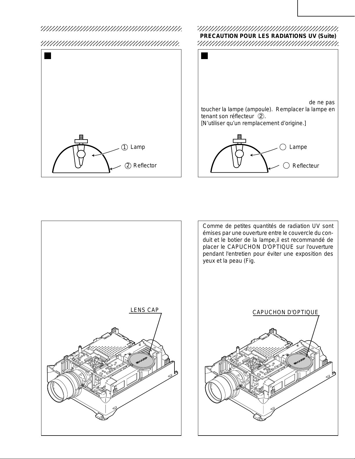
Lamp Replacement
Note:
Since the lamp reaches a very high temperature
during units operation replacement of the lamp
should be done at least one hour after the power
has been turned off. (to allow the lamp to cool off.)
Installing the new lamp, make sure not to touch the
lamp (bulb) replace the lamp by holding its reflector
2.
[Use original replacement only.]
Lamp
1
Reflector
2
DANGER ! –– Never turn the power on without the
lamp to avoid electric-shock or damage of the
devices since the stabilizer generates high voltages
at its start.
234567890123456789012345678901212345678901234
PRECAUTION POUR LES RADIATIONS UV (Suite)
234567890123456789012345678901212345678901234
Remplacement de la lampe
Remarque:
Comme la lampe devient très chaude pendant le
fonctionnement de l’unité, son remplacement ne doit
être effectué au moins une heure après avoir coupé
l’alimentation (pour permettre à la lampe de refroidir).
En installant la nouvelle lampe, s’assurer de ne pas
toucher la lampe (ampoule). Remplacer la lampe en
tenant son réflecteur 2.
[N’utiliser qu’un remplacement d’origine.]
1
Lampe
2
Reflecteur
DANGER ! –– Ne jamais mettre sous tension sans
la lampe pour éviter un choc électrique ou des
dommages des appareils car le stabilisateur génère
de hautes tensions à sa mise en route.
Since small amounts of UV-Radiation are emitted
from an opening between the duct cover and the
lamp housing, it is recommended to place the LENS
CAP on the opening during servicing to avoid eye
and skin exposure (Fig. 1).
Note: Please obtain a lens cap before servicing a
model XV-DW100U that is received without
one.
LENS CAP
Comme de petites quantités de radiation UV sont
émises par une ouverture entre le couvercle du conduit et le botier de la lampe,il est recommandé de
placer le CAPUCHON D'OPTIQUE sur l'ouverture
pendant l'entretien pour éviter une exposition des
yeux et la peau (Fig. 1).
Remarque: Priére de se procurer un capuchon
d'optique acant d'entretien un modéle
XV-DW100U qui est livré sans.
CAPUCHON D'OPTIQUE
Figure 1.
Figure 1.
5
Page 6
XV-DW100U
2
WARNING: High brightness light source, do not stare into the beam of light, or view directl y . Be especially
careful that children do not stare directly in to the beam of light.
WARNING: TO REDUCE THE RISK OF FIRE OR ELECTRIC SHOCK, DO NOT EXPOSE THIS UNIT TO
MOISTURE OR WET LOCATIONS.
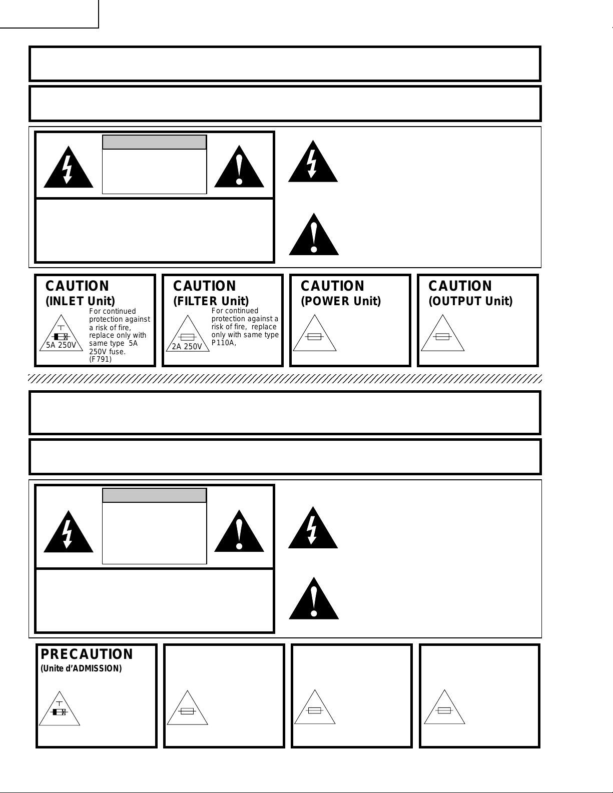
CAUTION
RISK OF ELECTRIC SHOCK.
DO NOT REMOVE SCREWS
EXCEPT SPECIFIED USER
SERVICE SCREW
CAUTION: TO REDUCE THE RISK OF ELECTRIC SHOCK,
NO USER-SERVICEABLE PARTS EXCEPT LAMP UNIT.
CAUTION
(INLET Unit)
5A 250V
234567890123456789012345678901212345678901234567890123456789012123456789012345678901234567890121
DO NOT REMOVE CABINET.
REFER SERVICING TO QUALIFIED SERVICE
PERSONNEL.
CAUTION
For continued
protection against
a risk of fire,
replace only with
same type 5A
250V fuse.
(F791)
(FILTER Unit)
2A 250V
For continued
protection against a
risk of fire, replace
only with same type
P110A, ANZEN
DENGU, 2A, 250V
117°C fuse.(TF751)
CAUTION
(POWER Unit)
2A 250V
The lighting flash with arrowhead within a
triangle is intended to tell the user that
parts inside the product are risk of electric
shock to persons.
The exclamation point within a triangle is
intended to tell the user that important
operating and servicing instructions are in
the manual with the projector.
CAUTION
For continued
protection against a
risk of fire, replace
only with same type
P100A, ANZEN
DENGU, 2A, 250V
103°C fuse.(TF701)
(OUTPUT Unit)
For continued
protection against a
risk of fire, replace
only with same type
0.8A 60V
SSTC, SOC, 0.8A,
60V fuse.
(F1401, F1402)
A VERTISSEMENT: Source lumineuse de grande intensité. Ne pas fixer le faisceau lumineux ou le regarder
directement. Veiller particulièrement à éviter que les enfants ne fixent directement le
faisceau lumineux.
A VERTISSEMENT : AFIN D’EVITER T OUT RISQUE D’INCENDIE OU D’ELECTR OCUTION, NE P AS PLA CER
CET APPAREIL DANS UN ENDROIT HUMIDE OU MOUILLE.
ATTENTION
RISQUE
D’ELECTROCUTION NE
PASRETIRER LES VIS, A
L’EXCEPTION DES VIS DE
REPARATION UTILISATEUR
SPECIFIEES
L’éclair terminé d’une flèche à l’intérieur
d’un triangle indique à l’utilisateur que les
pi‘eces se trouvant dans l’appareil sont
susceptibles de provoquer une décharge
électrique.
Le point d’exclamation à l’intérieur d’un
ATTENTION: POUR EVITER TOUT RISQUE
D’ELECTR OCUTION, NE PAS RETIRER LE CAPOT.
AUCUNE DES PIECES INTERIEURES N’EST REPARABLE
PAR L’UTILISATEUR, A L’EXCEPTION DE L’UNITE DE
LAMPE. POUR TOUTE REPARATION, S’ADRESSER A UN
PRECAUTION
(Unite d’ADMISSION)
5A 250V
TECHNICIEN D’ENTRETIEN QUALIFIE.
PRECAUTION
Pour une protection
continue contre les
risques d’incendie,
ne remplacer
qu’avec un fusible
5A 250V du même
type.
(F791)
(Unité de FILTRATION)
2A 250V
Pour une protection
continue contre un
risques d’incendie, ne
remplacer qu’avec un
fusible P110A, ANZEN
DENGU 2A 250V,
117°C du même type.
(TF751)
PRECAUTION
(Unité de PUTSSANCE)
2A 250V 0.8A 60V
triangle indique à l’utilisateur que les
instructions de fonctionnement et
d’entretien sont détaillées dans les
documents fournis avec le projecteur.
PRECAUTION
Pour une protection
continue contre un
risques d’incendie, ne
remplacer qu’avec un
fusible P100A, ANZEN
DENGU 2A 250V,
103°C du même type.
(TF701)
(Unité de SORTIE)
Pour une protection
continue contre un
risques d’incendie, ne
remplacer qu’avec un
fusible SSTC, SOC,
0.8A 60V du même
type.
(F1401, F1402)
6
Page 7
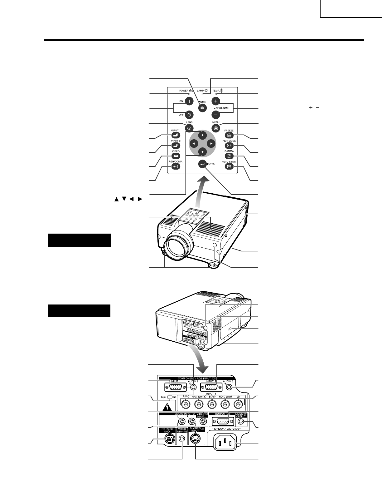
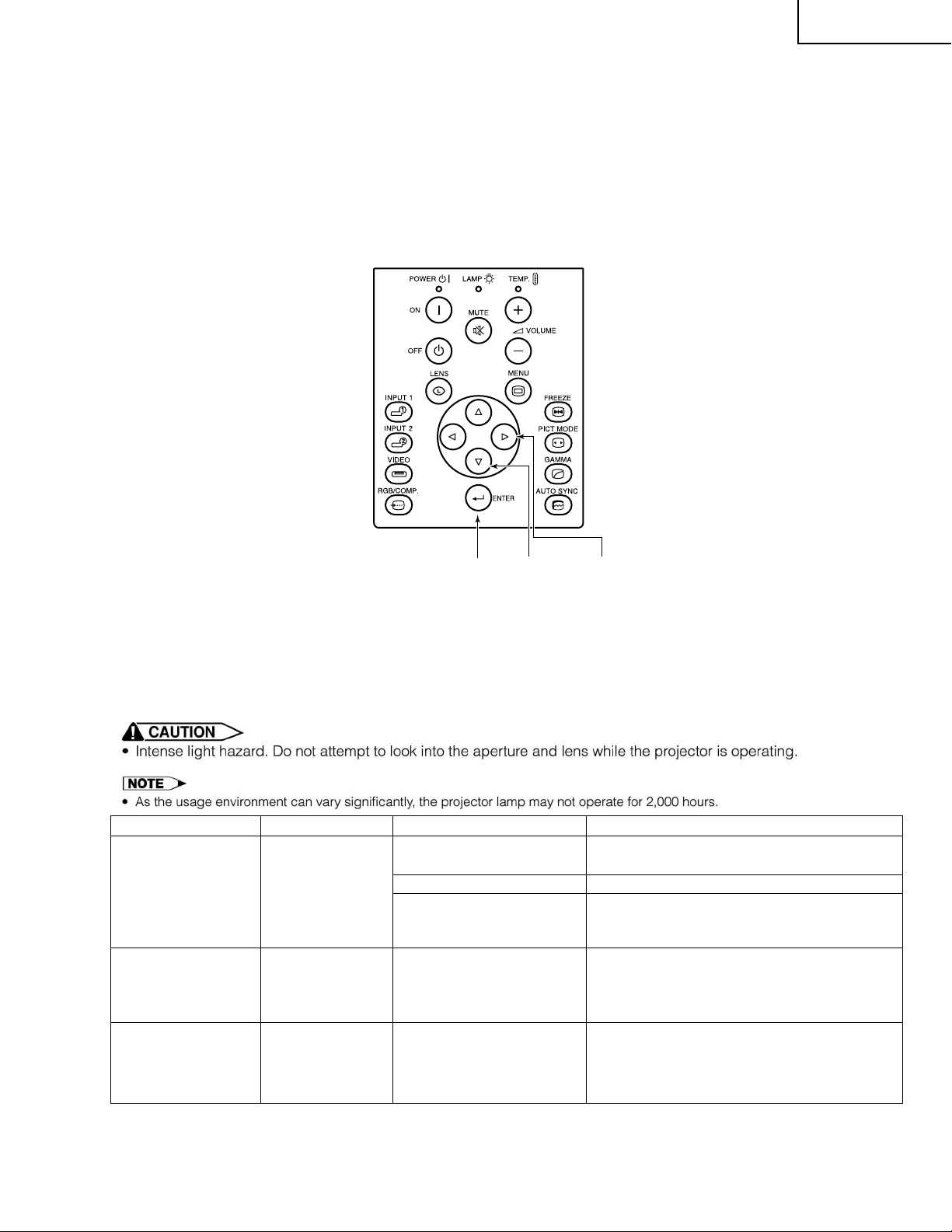
Location of Controls
Numbers next to the part names refer to the main pages in this manual where the topic is explained.
XV-DW100U
Projector
POWER buttons (ON/OFF)
RGB/COMPONENT button
ADJUSTMENT buttons
Front and Top View
MUTE button
POWER indicator
LENS button
INPUT 1 button
INPUT 2 button
VIDEO button
(
/ / / )
Speakers
LAMP REPLACEMENT
indicator
TEMPERATURE WARNING
indicator
VOLUME buttons (
MENU button
FREEZE button
PICTURE MODE button
GAMMA button
AUTO SYNC button
ENTER button
Cooling fan (Exhaust vent)
/ )
Side and Rear View
AUDIO INPUT 1 terminal
(3.5 mm stereo minijack)
INPUT 1 port (HD 15)
15 pin/BNC switch
VIDEO INPUT terminal: RCA
AUDIO INPUT terminals: RCA
control input terminal
Foot releases
RS-232C port
(9-pin Mini DIN)
WIRED REMOTE
Air filter/Cooling fan (Intake vent)
Remote control sensor
Remote control sensor
Cooling fan (Intake vent)
Kensington Security Standard
connector
Carrying handle
INPUT 2 port (HD 15)
AUDIO INPUT 2 terminal
(3.5 mm stereo minijack)
INPUT 1 terminals: BNC (R
R
), G/G sync (Y), B (PB), HD
(P
(C sync), VD)
OUTPUT port (HD 15)
AUDIO OUTPUT terminal
(3.5 mm stereo minijack)
AC socket
S-VIDEO INPUT terminal
(4-pin Mini DIN)
7
Page 8
XV-DW100U
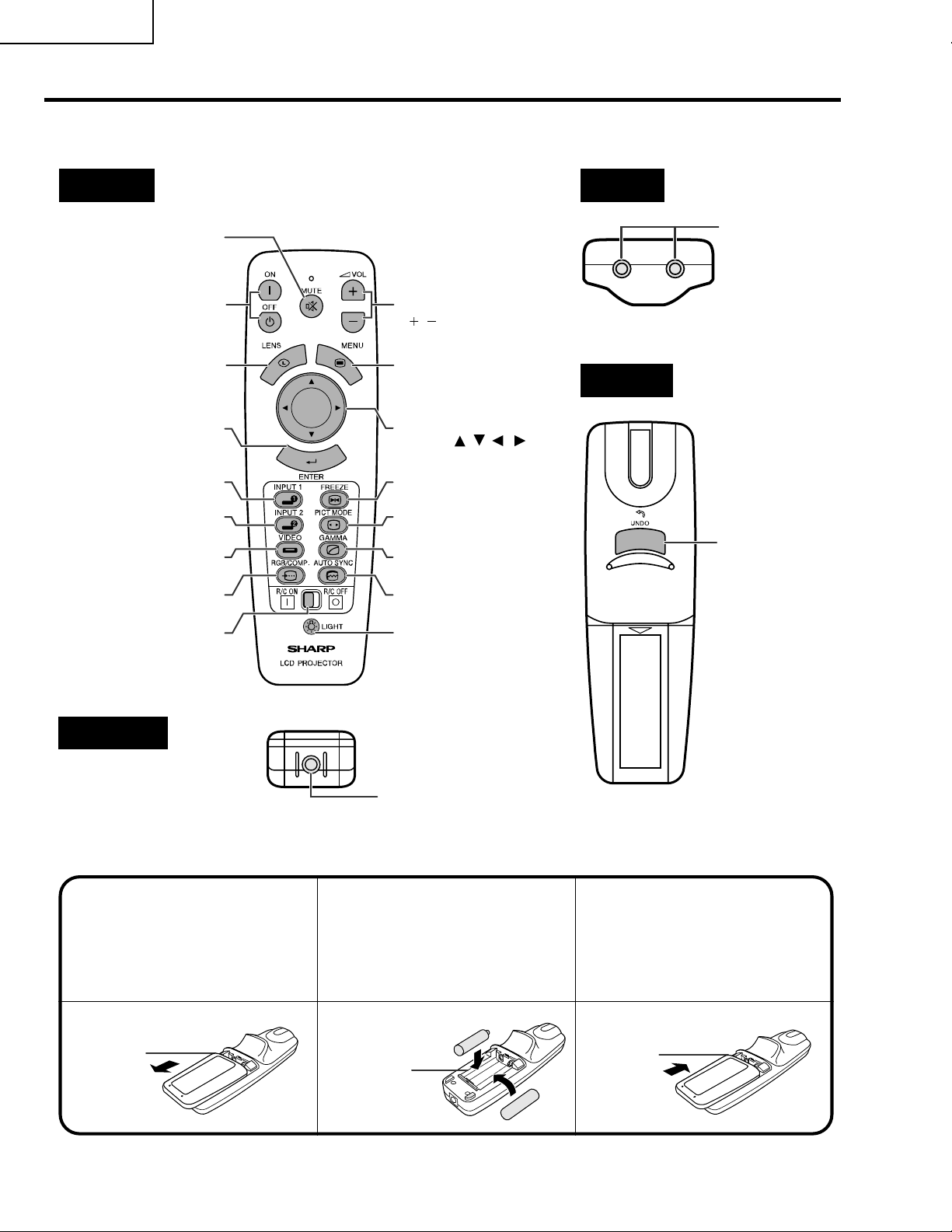
Operating the Wireless Mouse Remote Control
Remote Control
Front View
MUTE button
POWER buttons
(ON/OFF)
ENTER button
INPUT 2 button
RGB/COMPONENT
MAIN POWER switch
emote control
button
VOLUME buttons
()
/
MENU buttonLENS button
ADJUSTMENT
buttons ( )
FREEZE buttonINPUT 1 button
PICTURE MODE
button
GAMMA buttonVIDEO button
AUTO SYNC button
BACKLIGHT button
/ / /
T op View
Remote control
signal transmitter
Rear View
UNDO
button
Bottom View
Wired remote control
input
Inserting the batteries
Press in on the arrow
13
mark and slide in the
direction of the arrow to
remove the battery cover.
Battery
cover
I
nsert two AA size batteries
2
for the remote control,
making sure their polarities
match the + and – marks
inside the battery
compartment.
Battery
compartment
Insert the side tabs of
the battery cover into
their slots and slide the
cover in until it is
properly seated.
Battery
cover
8
Page 9
XV-DW100U
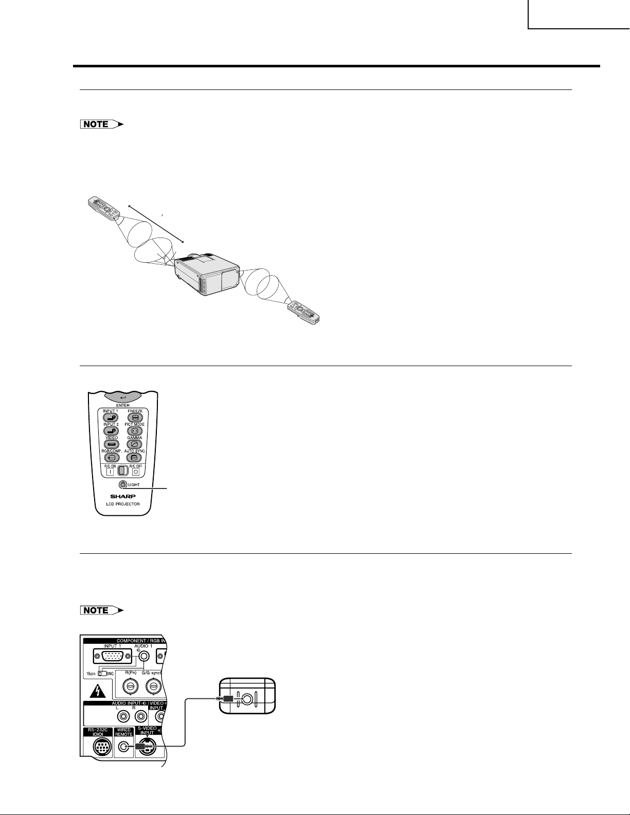
Remote Control Positioning
• The remote control can be used to control the projector within the ranges shown below.
• The signal from the remote control can be reflected off the screen for easy operation. However, the effective distance of the
signal may differ due to the screen material.
Controlling the Projector
Remote control
23 (7 m)
30˚
45˚
30˚
45˚
30˚
Remote control
Using the remote control in a dark room
Press BACKLIGHT to turn on the backlights of the operation buttons for about five seconds.
Remote control
BACKLIGHT button
Wired Remote Control
When the remote control cannot be used due to the range or positioning of the projector (rear projection, etc.),
connect a 3.5 mm stereo minijack cable (sold separately) from the wired r emote control input on the bottom of the
remote control to the WIRED REMOTE control input terminal on the rear of the projector.
• The signal transmitter does not operate when the cable is connected to the remote control.
Remote control
3.5 mm stereo minijack cable
(sold separately)
9
Page 10
XV-DW100U
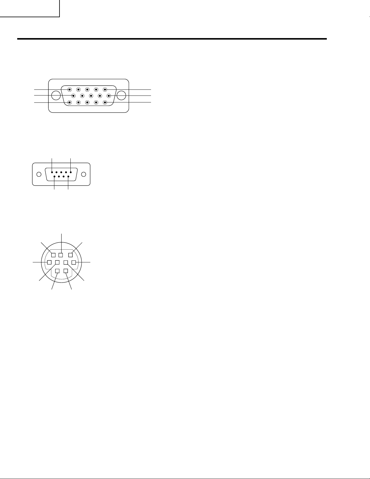
Connection Pin Assignments
Analog
Computer 1 and 2 Signal Input Ports: 15-pin mini D-sub female connector
5
10
15
RS-232C ort:
RS-232C
P
Terminal: 9-pin Mini DIN connector
Computer Input
Analog
1. Video input (red)
2. Video input
(green/sync on green)
1
6
11
3. Video input (blue)
4. Reserve input 1
5. Composite sync
6. Earth (red)
7. Earth (green/sync on green)
8. Earth (blue)
9-pin D-sub male connector of the DIN-D-sub RS-232C cable
Pin No. Signal Name I/O Reference
51
96
1 CD Not connected
2 RD Receive Data Input Connected to internal circuit
3 SD Send Data Output Connected to internal circuit
4 ER Not connected
5 SG Signal Ground Connected to internal circuit
6 DR Data Set Ready Output Not connected
7 RS Request to Send Output Connected to internal circuit
8 CS Clear to Send Input Connected to internal circuit
9 CI Not connected
9. Not connected
10. GND
11. GND
12. Bi-directional data
13. Horizontal sync signal
14. Vertical sync signal
15. Data clock
9
5
21
8
7
4
Pin No. Signal Name I/O Reference
1 VCC + 3.3 V (Reserved) Output Not connected
2 RD Receive Data Input Connected to internal circuit
3 SD Send Data Output Connected to internal circuit
4 EXIR Detector of Option Unit Input Not connected
36
5 SG Signal Ground Connected to internal circuit
6 ERX IR Receive Signal from Input Not connected
7 RS Request to Send Output Connected to internal circuit
8 CS Clear to Send Input Connected to internal circuit
9 ETX IR Transmit Signal Output Not connected
(Reserved)
IR Amplifire (Reserved)
(Reserved)
10
Page 11
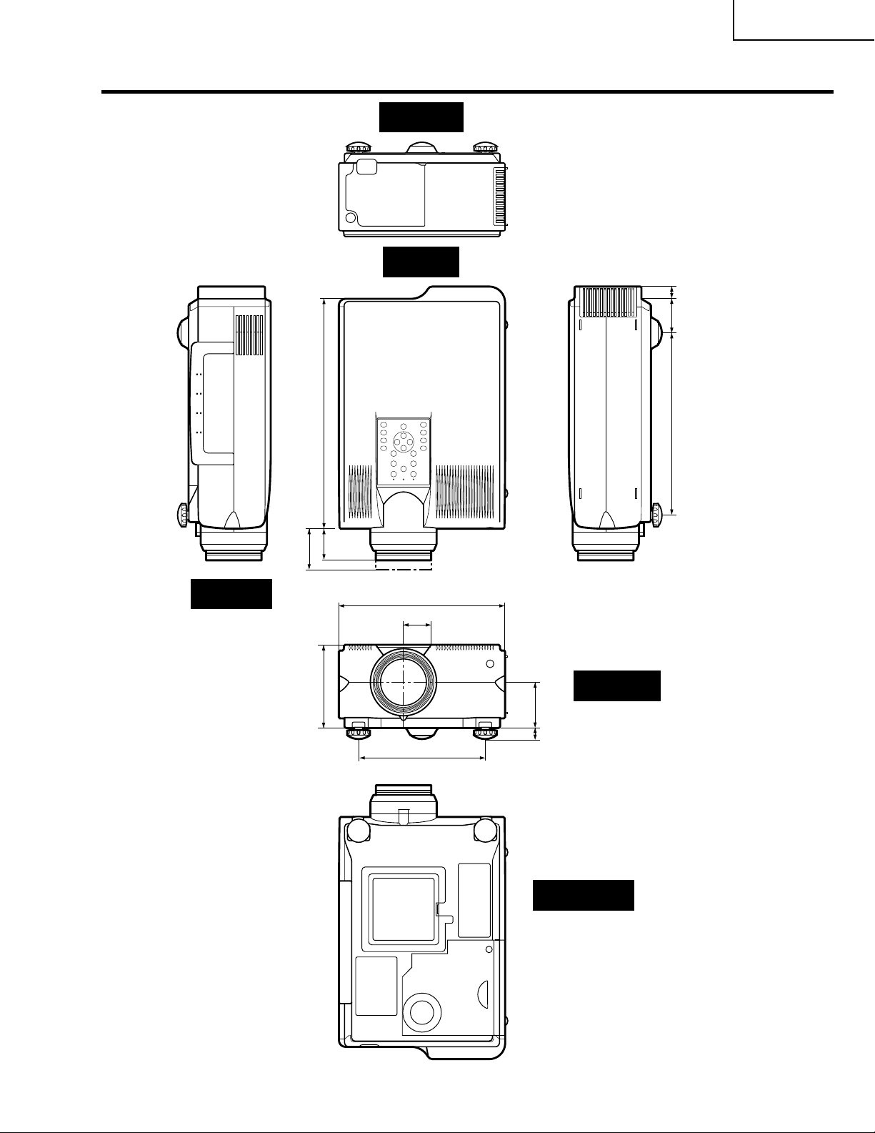
Dimensions
(356)
64
/
1
14
Rear View
T op View
(19.5)
64
/
49
(53)
64
/
5
2
(282)
32
/
3
11
XV-DW100U
Side View
(60.5)
8
/
3
2
(55.5)
16
/
3
2
(129)
64
/
5
5
10 9/32 (261)
9
1
/64 (29)
53
/64 (199)
7
Front View
(71)
64
/
51
(17) 2
64
/
43
Bottom View
11
Units: inches (mm)
Page 12
XV-DW100U
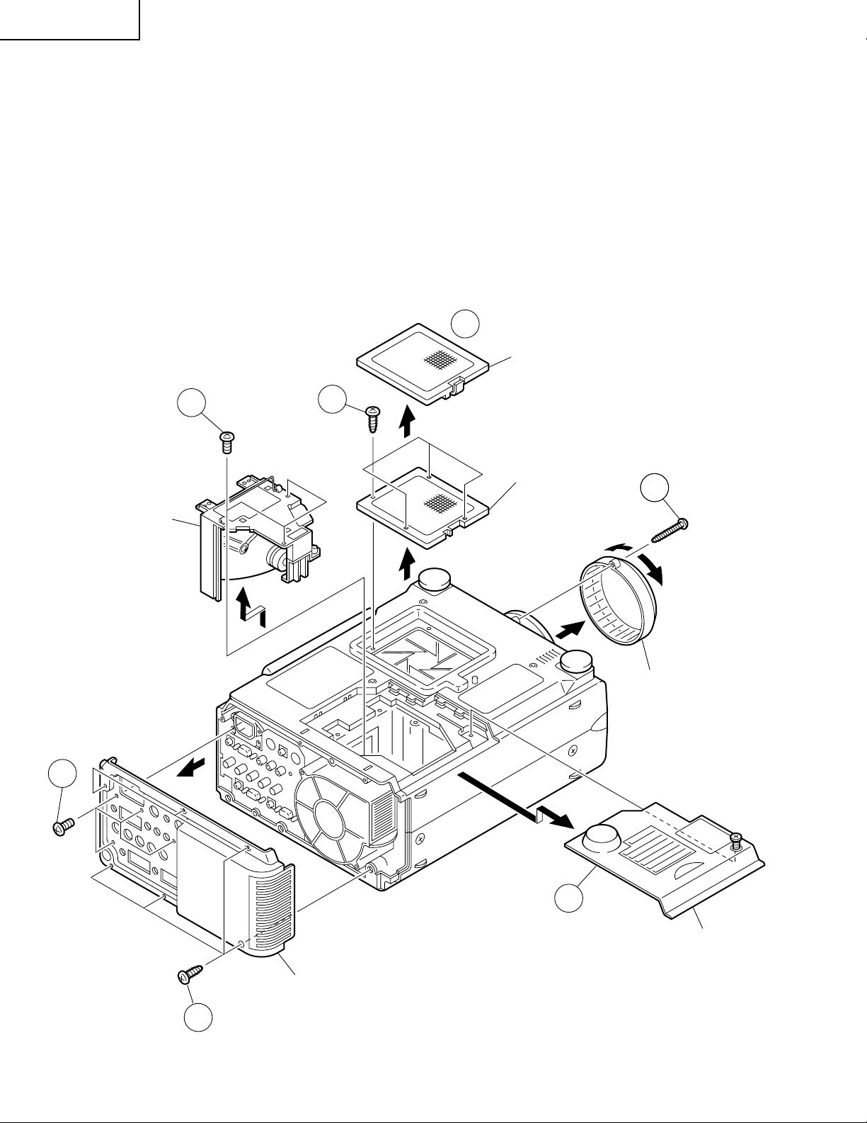
REMOVING OF MAJOR PARTS
1.Removing the Intake cover, lamp unit and lens cover.
1-1. Detach the Intake cover.
1-2. Remove the four lock screws off the inner filter frame. Detach the frame.
1-3. Remove the lock screw off the lamp cover. Slide and detach the lamp cover.
1-4. Remove the three lock screws off the lamp unit and detach the lamp unit.
1-5. Remove the lens cover lock screw, and turn and detach the lens cover.
2.Removing the rear cabinet.
2-1. Remove the four lock screws off the terminal board.
2-2. Remove the six lock screws off the rear cabinet. Detach the rear cabinet.
1-1
Intake Cover
2-1
Lamp Unit
1-4
1-2
Inner Filter Frame
1-5
Lens Cover
2-2
1-3
Lamp Cover
Rear Cabinet
12
Page 13
XV-DW100U
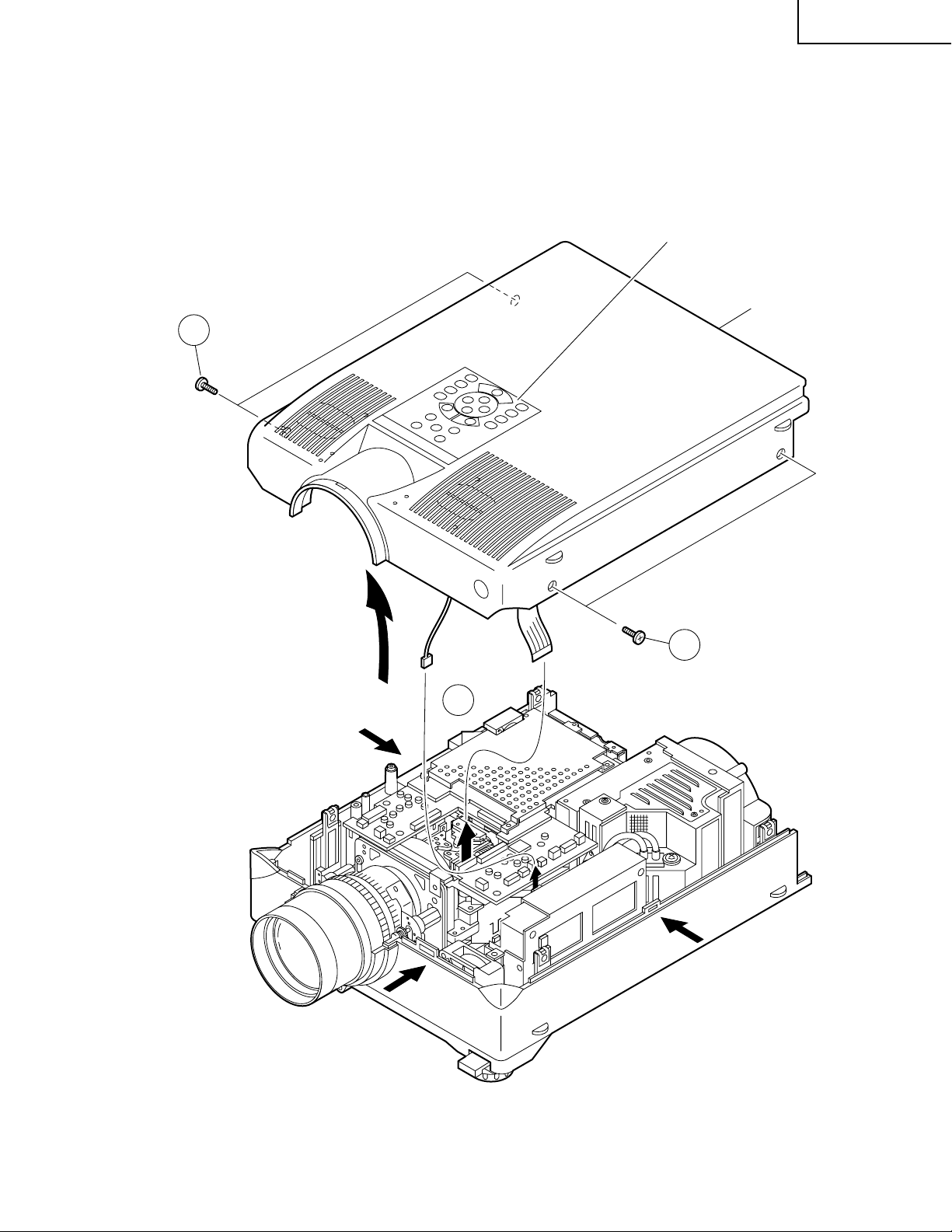
3.Removing the top cabinet.
3-1. Remove the four lock screws off the top cabinet.
3-2. Unhook the top cabinet by pressing the center of both sides of the bottom cabinet as well as the hook on the
front (all marked with `). Slowly lift the back of the cabinet and disconnect the operation key unit connector
(KY) and the speaker connector (SP). Then detach the top cabinet.
Operation Key Unit
Top Cabinet
3-1
`
`
(SP)
3-2
(KY)
3-1
`
13
Page 14
XV-DW100U
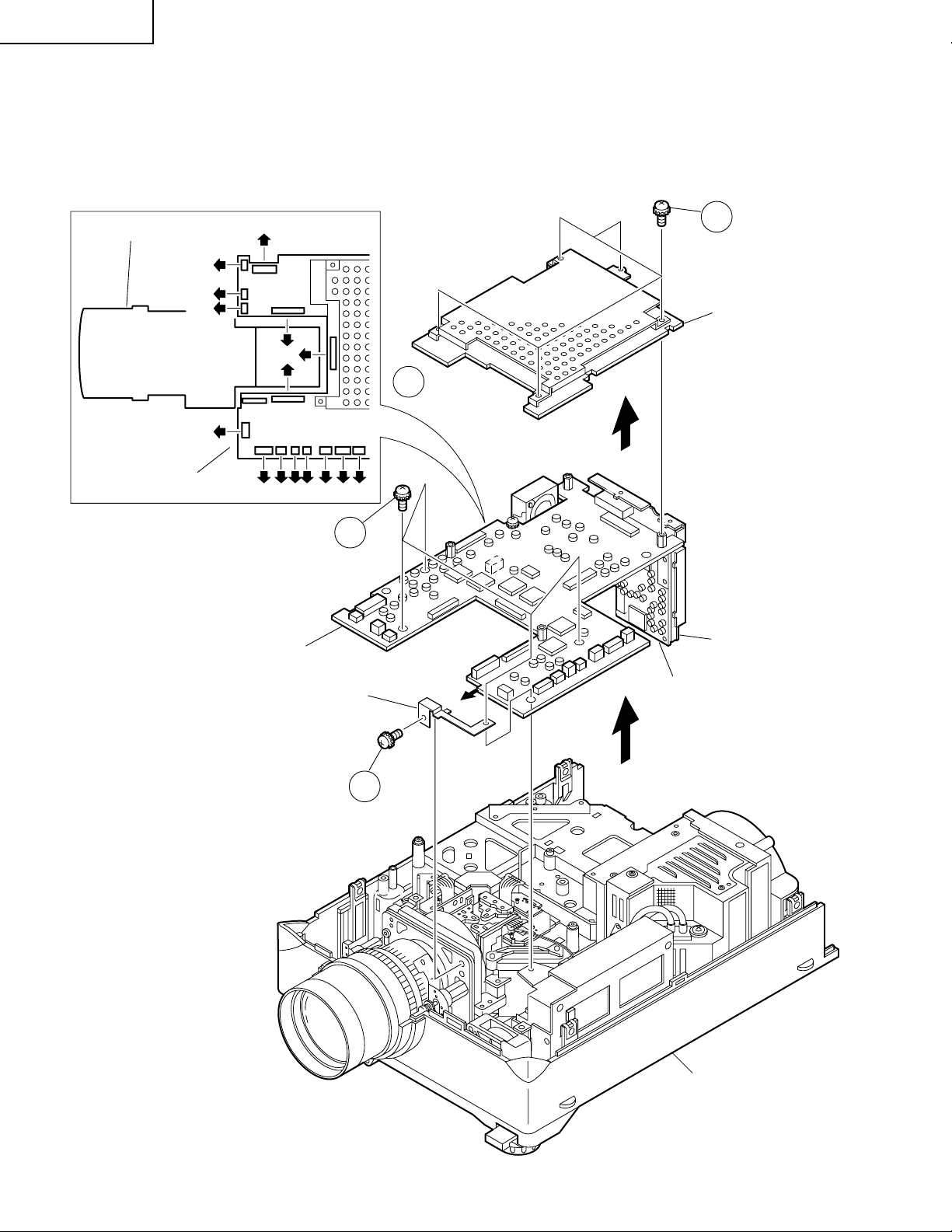
4.Removing the PWB units
4-1. Remove the five lock screws off the PC I/F unit. Lift and detach the unit off the output unit.
4-2. Disconnect the connectors from the output unit.
4-3. Remove the four lock screws off the output units. Remove also the lock screw off the ground fixture and
detach the ground fixture. Lift and detach the output, terminal and signal units.
Optical Mechanism Unit
(FD)
(F)
(AZ)
(FE)
Output Unit
Output Unit
(EA)
(RP)
(GP)
(BP)
(RA) (D)(Q)(L) (FA)(SO)(FB)
4-3
4-1
PC I/F Unit
4-2
Terminal Unit
Ground Fixture
Signal Unit
4-3
Bottom Cabinet
14
Page 15
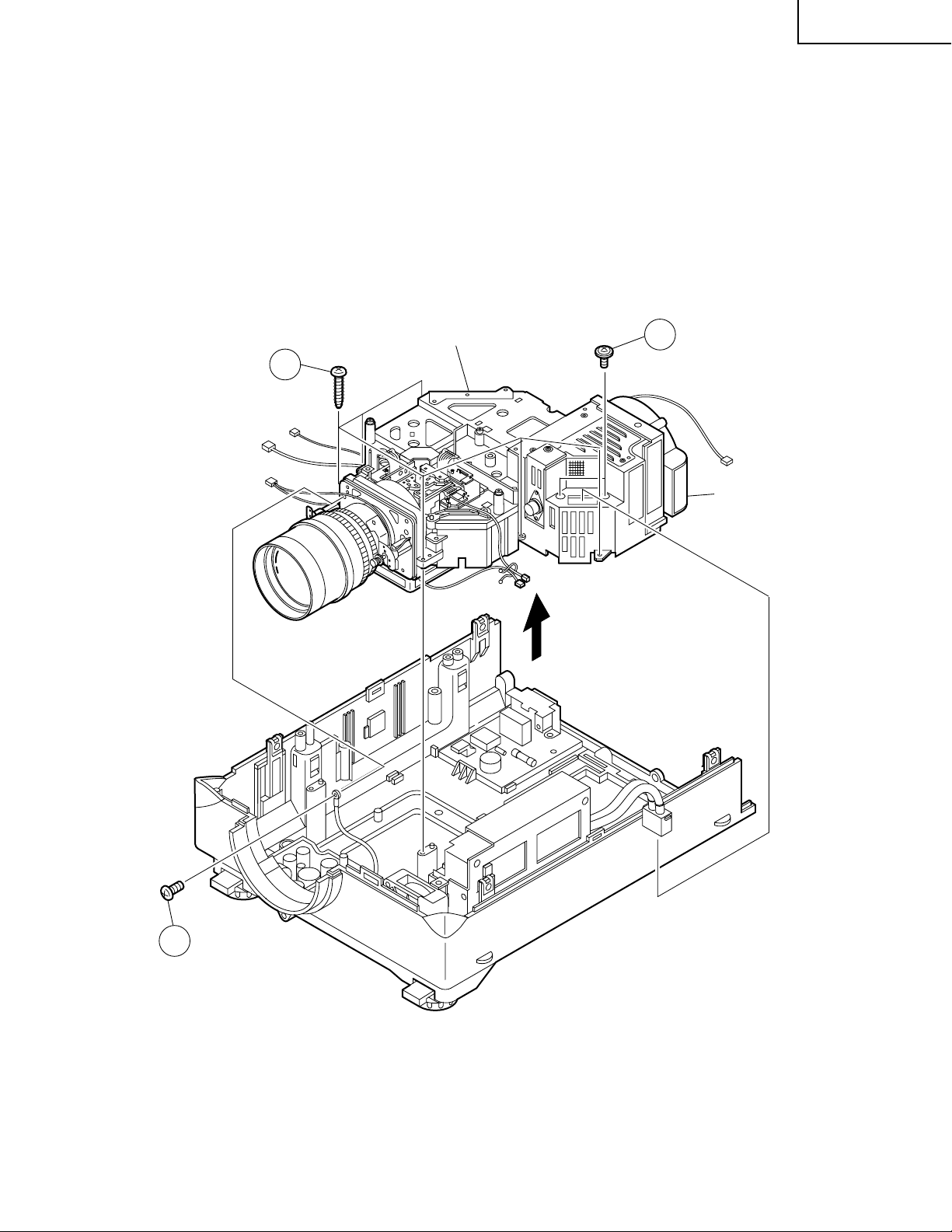
5.Removing the optical mechanism unit
5-1. Remove the two lock screws off the lamp socket holder. Detach the holder.
5-2. Disconnect the ground wire from the power unit.
5-3. Remove the six lock screws off the optical mechanism unit. Lift and detach the unit.
XV-DW100U
5-3
Optical Mechanism Unit
5-1
Duct Fan Unit
5-2
15
Page 16
XV-DW100U
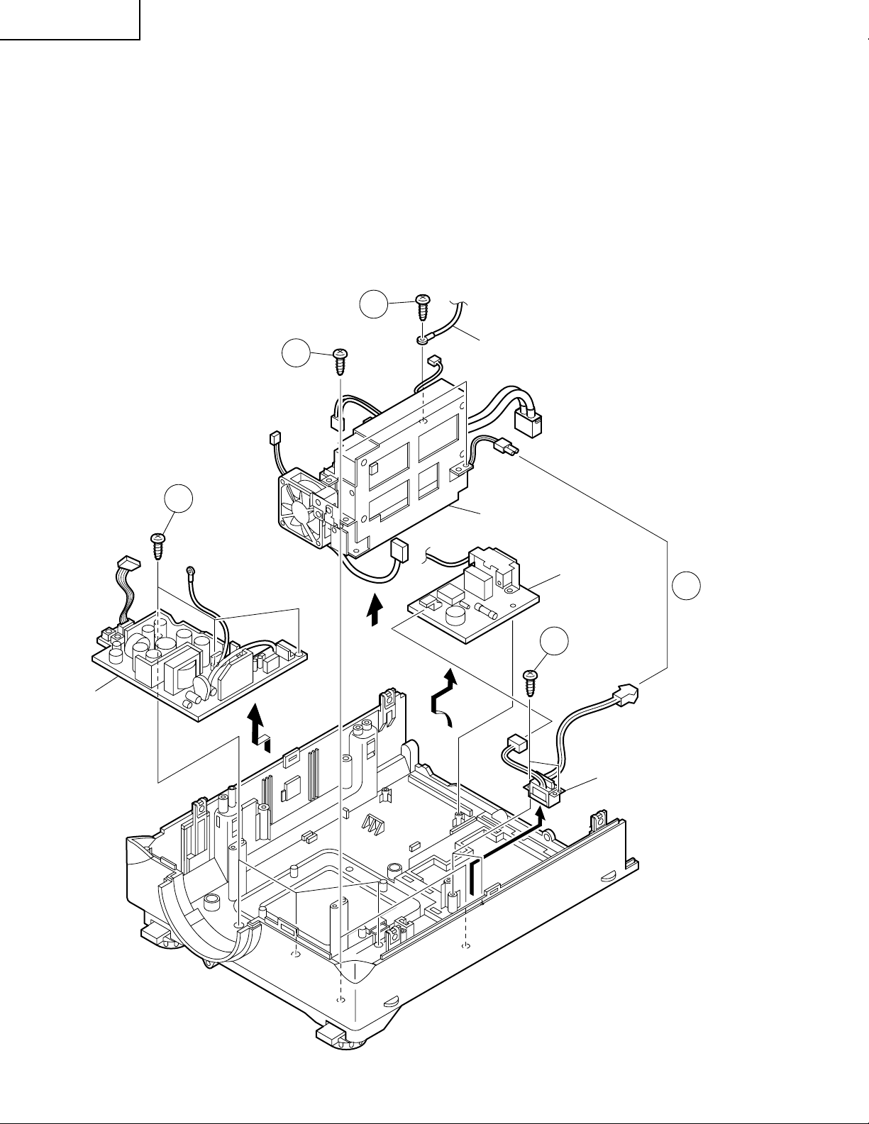
6.Removing the ballast / filter / sound-out unit assembly.
6-1. Disconnect the connector (BA) from the AC power switch.
6-2. Disconnect the ground wire from the inlet unit.
6-3. Remove the two lock screws off the ballast/filter/sound-out unit assembly. Detach the assembly.
7.Removing the power unit
7-1. Remove the three lock screws off the power PWB. Detach the power unit.
8.Removing the AC power switch and inlet unit.
8-1. Remove the two lock screws off the AC power switch, disconnect the connector (PA) from the inlet unit, and
detach the AC power switch and the inlet unit.
6-2
Power Unit
7-1
6-3
to Inlet Unit
Ballast/Filter/
Sound-Out Unit
Inlet Unit
6-1
8-1
(BA)
(PA)
AC Power Switch
(for Lamp replacement)
16
Page 17
XV-DW100U
RESETTING THE T OTAL LAMP TIMER
When the lamp has been replaced, reset the total lamp timer in the following steps.
Resetting procedure
1. While holding down the “ENTER”, “ADJ."” and “ADJ.|” keys on the set at the same time, turn on the POWER
ON key.
2. Now the total lamp timer is reset to zero. “000H” appears on the screen.
ENTER ADJ." ADJ.|
Lamp
The lamp in this projector operates for approximately 2,000 cumulative hours, depending on the usage environment. It is recommended that the lamp be replaced after 1,900 cumulative hours of ues or when you notice a
significant deterioration of the picture and color quality. The lamp usage time can be checked with the On-screen
Display.
Maintenance Indicator
TEMPERATURE
WARNING indicator
LAMP REPLACEMENT indicator
POWER indicator
The internal
temperature is
abnormally high.
The lamp does
not light up.
The POWER
indicator flashes
in red when the
projector is on.
Condition
· Blocked air intake.
· Clogged air filter.
· Cooling fan breakdown.
· Internal circuit failure.
· Burnt-out lamp.
· Lamp circuit failure.
· The bottom filter cover is
open.
Problem
Possible Solution
· Relocate the projector to an area with
proper ventilation.
· Clean the filter.
· Take the projector to your nearest Authorized Sharp Industrial LCD Products
Dealer or Service Center for repair.
· Carefully replace the lamp.
· Take the projector to your nearest Authorized Sharp Industrial LCD Products
Dealer or Service Center for repair.
· Securely install the bottom filter cover.
17
Page 18
XV-DW100U
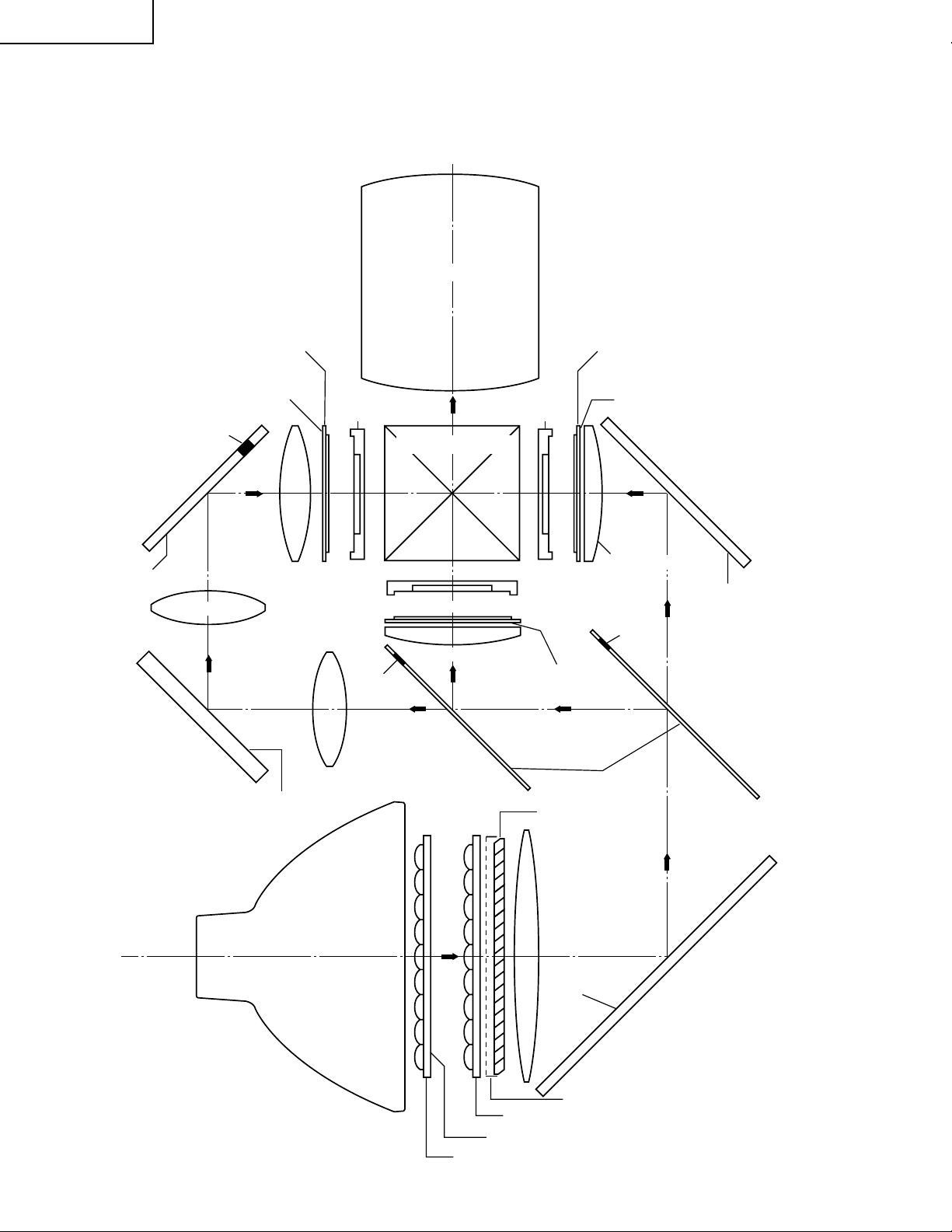
THE OPTICAL UNIT OUTLINE
Layout of the optical system
Note: Layout for positioning the optical system.
Projection Lens
Dichroic coating
(B reflection)
Incident polarizing plate B
Dichroic coating
(B transmission)
Marking
M6
BLUE
B reflector
G03 L2
Relay lens 3
Relay lens 2
G02 L2
AL-coated mirror B
M4
AL-deposited face
B-LCD
Cross dichroic prism
G-LCD
Incident polarizing plate G
Marking
G01
Relay lens 1
Condenser lens G
GREEN
BLUE
G reflector
* M3
R-LCD
Dichroic coating
(G transmission)
Dichroic coating
PBS(polarization
beam splitter)
Incident polarizing plate R
Dichroic coating
(R transmission)
AL-coated mirror R
M5
Condenser lens R
AL-deposited face
RED
Marking
(R reflection)
M2
B/G reflector
* The M3 mirrors have a coating
wedge (for different film thickness). Set up these mirrors, with
their markings positioned as
shown above, so that their
coated faces and both sides be
in the correct directions.
UHP lamp
(Light source)
L1
AL-deposited
face
Fly-eye lens (outgoing light)
UV-IR coating
Fly-eye lens (incoming light)
18
M1
AL-coated mirror W
PBS aperture
Page 19

XV-DW100U
CONVERGENCE AND FOCUS ADJUSTMENT
» Start the convergence and focus adjustments with the top cabinet and the LCD cover
removed but the power on. Use the remote control to adjust the image. Take the following procedures.
1. Focusing the projection lens
(A) Replacing all the 3 LCD panels
1. Before replacing all the 3 LCD panels, project an image on the screen and bring it into focus.
2. Replace the panels with new ones. But until the focus has been completely readjusted, be careful not to
change the distance between the set and the screen, nor to move the projection lens focus and zoom
rings.
If the focus is readjusted with a different positional relation, the relation betw een the projection distance
and the screen size is affected. In other words, a short-distance image (40 WIDE, for example) ma y get
out of the focus range, or a long-distance image (300 WIDE, for example) may come out of focus.
(B) Replacing 1 or 2 of the 3 LCD panels
1. In adjusting the focus after replacement of one or two LCD panels, project an image on the screen and turn
the projection lens focus ring to get the non-replaced LCD panel into focus.
2. But until the focus has been completely adjusted for the new LCD panels, be careful not to change the
distance between the set and the screen, nor to move the projection lens focus and zoom rings.
(If the distance has been changed or the projection lens readjusted, repeat the above steps 1 and 2.)
2. Adjusting the G-LCD panel
(A) Focus adjustment. (Make this adjustment on the white-only screen.)
1. Right-and-left focus adjustment (θY direction) .
Loosen the lock screws "b" and "c" and insert the eccentric screwdriver into the notch and hole "b". Turn
the screwdriver until the right and left halves on the screen get into focus.
First get the right and left halves in balance. Then improve the accuracy while making the adjustment 2
below.
2. Top-center-bottom focus adjustment (θX and Z directions).
Loosen the lock screws "a" and "c" and insert the eccentric screwdriver into the notch and hole "a" or "c".
Turn the screwdriver until the top, center and bottom on the screen get into focus. In adjusting this top-tobottom focus, temporarily tighten the lock screw "b" to fix the θY direction adjustment.
3. Repeat the above steps 1 and 2 to finely adjust the focus. Finally tighten up all the lock screws.
Notes :
1 Carefully proceed with the focus adjustment because the adjusting directions are correlated.
2 In adjusting the convergence and focus, do not move the projection lens zoom and focus rings until the end
of all the adjustments.
(B) Convergence adjustment
» The G-LCD panel has no convergence adjustment mechanism. Use this panel as convergence adjustment
reference.
3. B-LCD panel adjustment (the same for the R-LCD panel)
(A) Focus adjustment
» Take the same procedure as for the G-LCD panel focus adjustment. Note that the adjustment r ange is small
in the Z direction. If the con vergence is quite diff erent between the B-LCD and G-LCD panels, roughly adjust
the convergence first and then the focus.
(B) Convergence adjustment
» Use a crosshatch pattern signal for this adjustment.
Make the adjustment just for the G-color and the relevant color.
(1) Loosen the convergence lock screw "d".
(2) With the G-LCD panel’s screen center as ref erence, adjust the B-LCD panel in the X, Y and θZ directions.
(3) Finally tighten up the convergence lock screw "d".
19
Page 20
XV-DW100U
Notes :
1 The eccentr ic cam is used for convergence adjustment. This means that the cam’s turning and the linear
movement are not always uniform.
2 This model is not equipped with the LCD image adjustment mechanism. This is because the dichroic prism
is used for image formation. When the LCD panels all get into the best focus, the images are almost
completely converged.
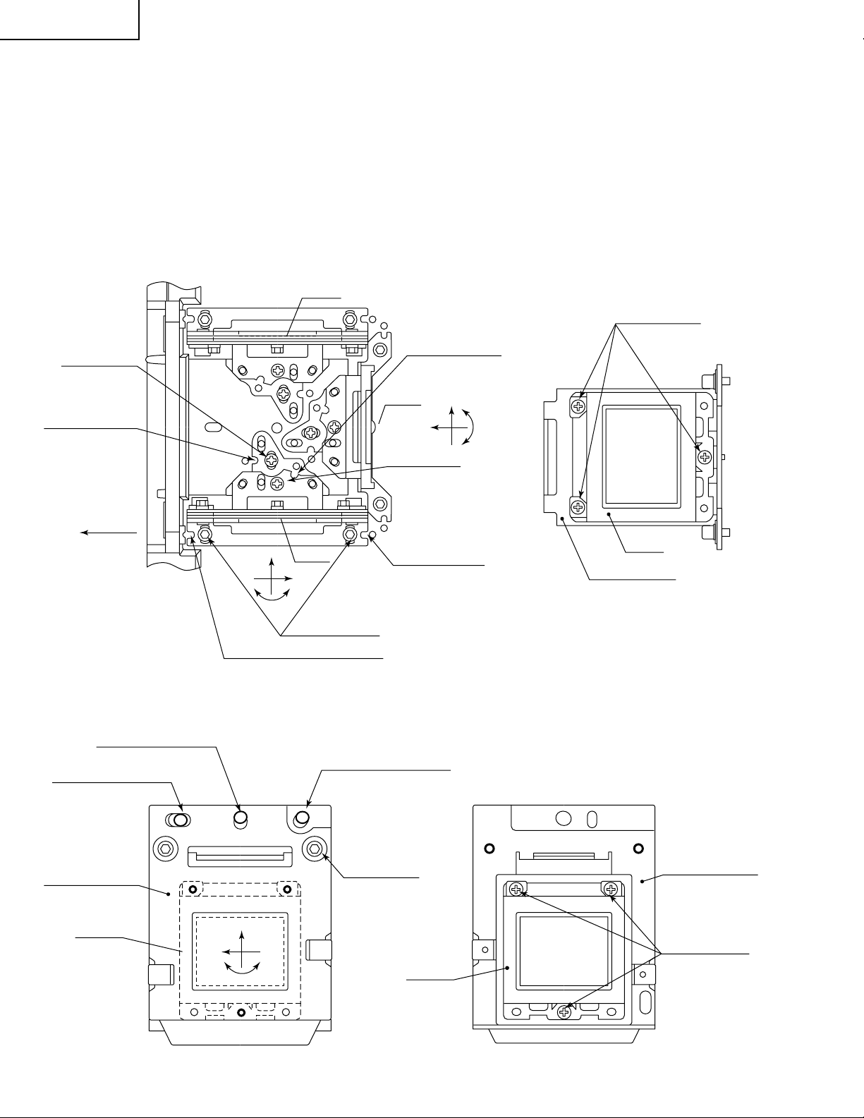
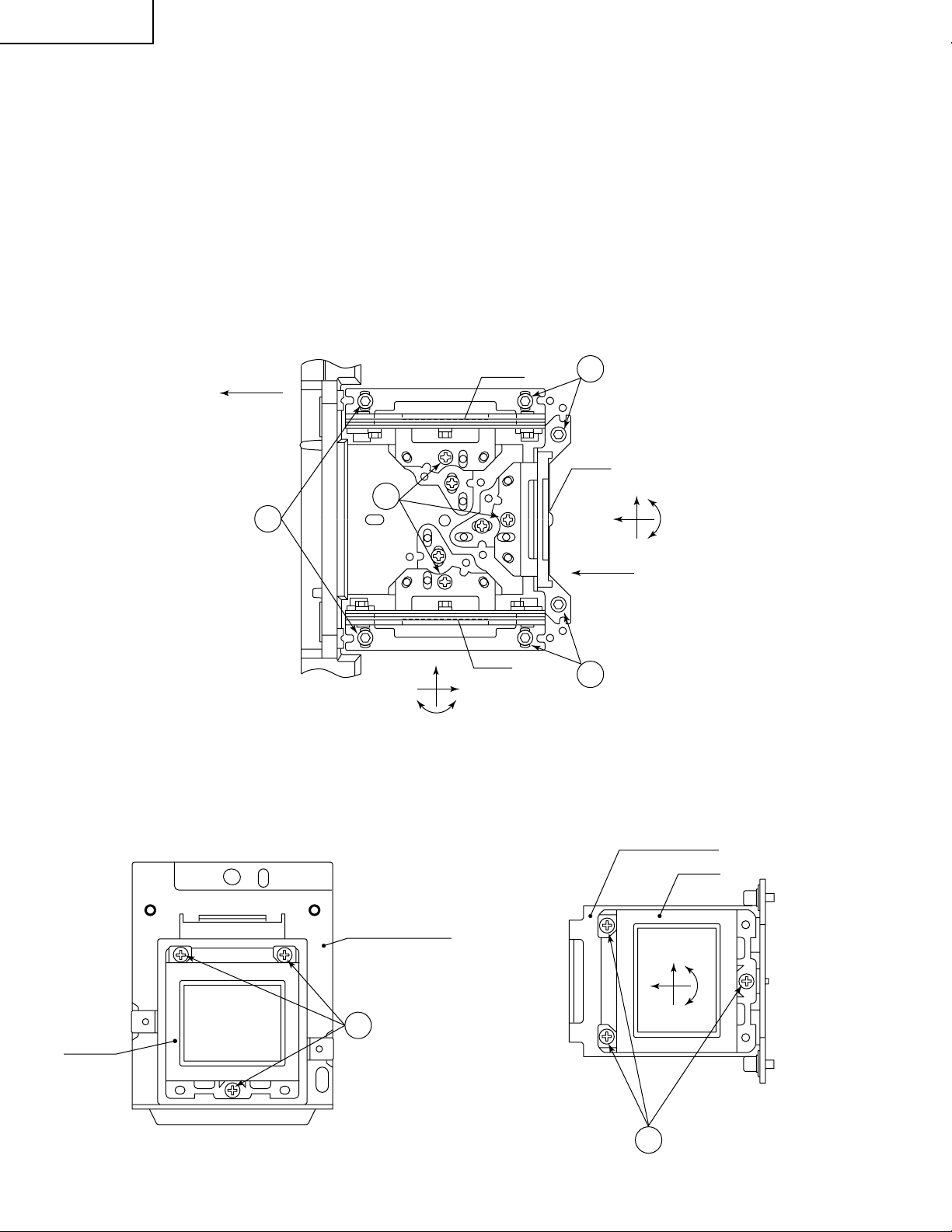
Convergence and Focus Adjustments Mechanism
TOP VIEW
Lock screw "a"
Notch and hole "a"
(Use an eccentric
screwdriver.)
FRONT
R-LCD
B-LCD
Z
X
θY
Lock screws "c"
Notch and hole "c"
(Use an eccentric screwdriver.)
Notch and hole "b"
(Use an eccentric
screwdriver.)
G-LCD
Lock screw "b"
(θY direction)
Notch and
hole "c"
(Use an eccentric
screwdriver.)
X
Z
SIDE VIEW
G-LCD panel
mounting screws
θY
G-LCD
G adjusting plate
SIDE VIEW (from inside)
Eccentric cam
(X direction adjustment)
Eccentric cam
(Y direction adjustment)
R•B adjusting plate
R•B-LCD
SIDE VIEW (from outside)
Eccentric cam
(θZ direction adjustment)
Lock screw "d"
(convergence
adjustment)
Y
X
θZ
R•B-LCD
R•B adjusting plate
R•B-LCD panel
mounting screws
20
Page 21
Convergence and Focus Adjustments at a Glance
2
5
16
R2
50
CUT
Adjustment directions
Adjustment Direction Definition Direction of LCD panel
X direction LCD right and left
Convergence Y direction LCD top and bottom
θZ direction Rotation around Z axis LCD turning axis
Z direction LCD optical axis
Focus θX direction Rotation around X axis LCD top-to-bottom flapping
θY direction Rotation around Y axis LCD right-to-left flapping
Convergence and Focus Adjustment for the Optical Mechanism
XV-DW100U
Color Adjustment Direction
X direction ±0.8mm Eccentric cam Eccentric cam adjusting wrench d Hex wrench
Convergence Y direction ±0.8mm Eccentric cam Eccentric cam adjusting wrench d Hex wrench
R/B θZ direction ±1° Eccentric cam Eccentric cam adjusting wrench d Hex wrench
colors Z direction ±0.8mm
Focus θX direction ±1°
θY direction ±1°
Z direction ±0.2mm
G color Focus θX direction ±1° Same as for R and B colors
θY direction ±1°
Movement
Position Adjusting tool
Notch and hole "a" & "c"
Notch and hole "a" & "c"
Notch and hole "b" & "c"
Eccentric screwdriver a, c
Lock screw
a, c
b, c
Tightening tool
Phillips
screwdriver,
*Hex wrench
Focus Adjustments the Other Way
Lock screw Position Related direction
a Notch and hole "a" Z and θX directions
b Notch and hole "b" θY direction
c Notch and hole "c" Z, θX and θY directions
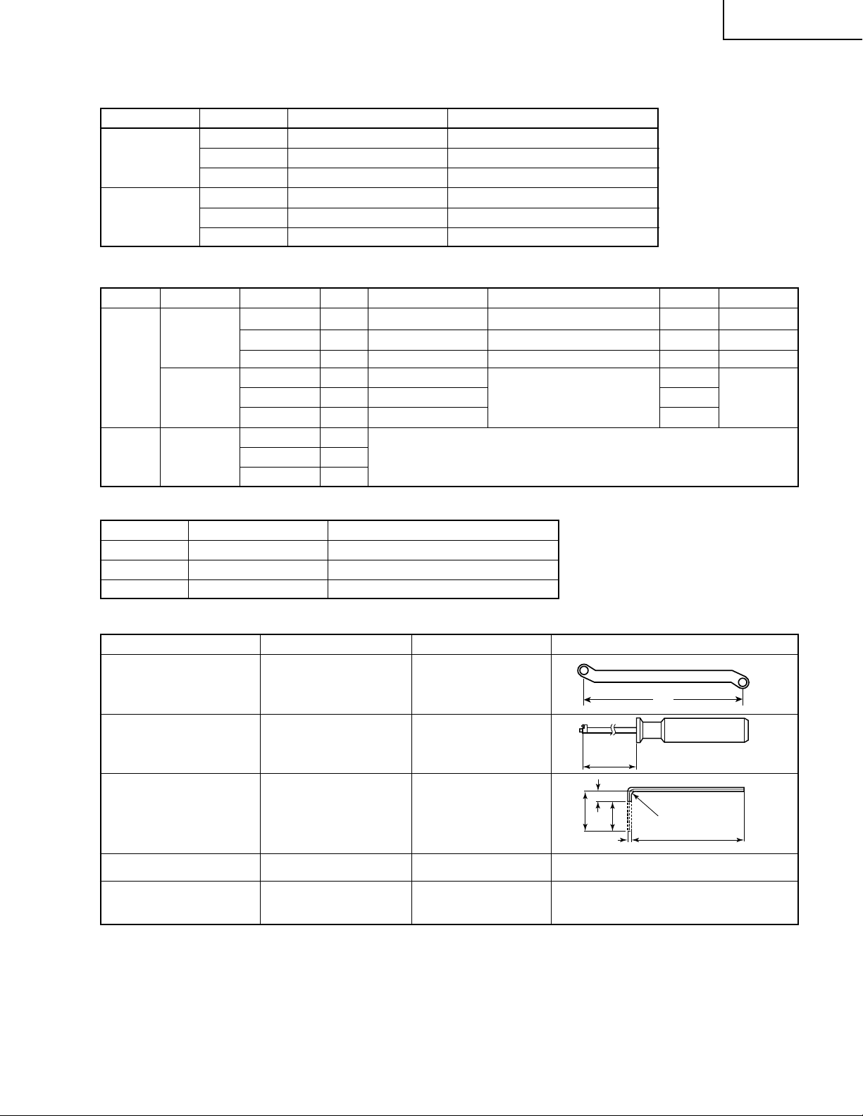
Convergence and Focus Adjusting and Tightening Tools
Tool Specific or General Tool code Configuration
Eccentric cam Specific 9DASPN-XGNV1U
adjusting wrench
80
Eccentric screwdriver Specific 9EQDRiVER-NV1A
100
Hex wrench General (redesigned) 9EQLNC-XGNV1U
Phillips screwdriver General — For M2.6 pan-head machine screw
*Hex wrench General —
21
Preferably use a 70 mm or longer
screwdriver (with a handle).
Page 22
XV-DW100U
Replacing the LCDs
With the top cabinet removed
(1)Disconnect the LCD flat cable from the output PWB connector.
(2)Remove the lock screws "b" and "c". Detach the R/B adjusting plate or the G adjusting plate together with the LCD
panel.
(3)Separate the LCD panel from the adjusting plate.
(4)Mount a new LCD panel in the reverse order of the above steps (1), (2) and (3).
~ Readjust the convergence and focus. Note that the G-LCD panel needs no convergence adjustment and has
a small adjustment range in the Z direction.
TOP VIEW
Lock screws "c"
R-LCD
FRONT
2
SIDE VIEW
2
Lock
screws "c"
Lock
screws "b"
2
G-LCD
X
θY
Z
~
θY
X
B-LCD
2
Lock screws "c"
Z
SIDE VIEW
G adjusting plate
G-LCD
R•B-LCD
R•B adjusting plate
3
R•B-LCD panel
mounting screws
22
X
θZ
Y
G-LCD panel
3
mounting screws
Page 23
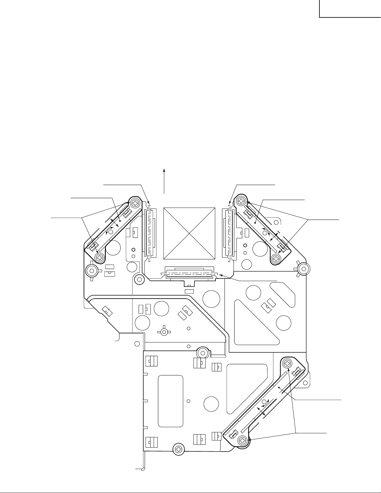
XV-DW100U
Adjusting the optical axis of the mirrors (M1, M5 and M6)
The optical axis must be readjusted if an eclipse happens with the R. G or B mirrors. Generally speaking,
this adjustment is needed when any of the internal optical components has been replaced.
Adjustment procedure required when any of the panels has been replaced or the convergence has been
adjusted
(1)Disconnect the flat cables of all the LCD panels.
(2)Let the lamp light up.
(3)To adjust the G mirror, shield the R and B mirrors with shielding plates (You can use a business card or the like to
block the light).
(4)Loosen the lock screw of the M1 adjust lever.
(5)Looking at the G image on the screen, turn or slide the M1 adjust lever until the eclipse on the screen disappears.
Tighten up the screw.
(6)To adjust the R mirror, shield the G and B mirrors and adjust the M5 adjust lever. For the B mirror, shield the R and
G mirrors and adjust the M6 adjust lever.
(Take the same steps 4 and 5 above.)
(7)Remove all the shielding plates to have a white image.
Make sure there is no eclipse.
M6
Lock screws
Shielding plate B
adjust lever
slide
turn
FRONT
Shielding plate R
M5
Shielding plate G
adjust lever
Lock screws
turn
slide
23
slide
turn
M1
adjust lever
Lock screws
Page 24
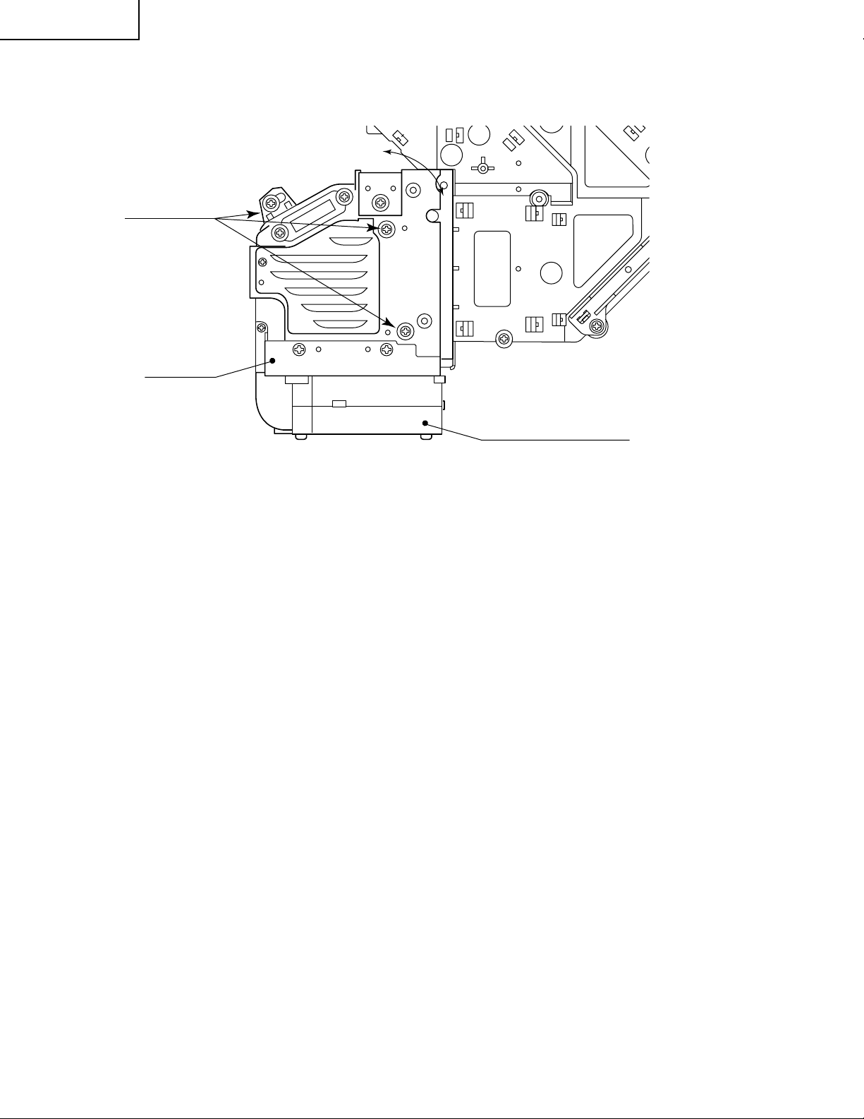
XV-DW100U
Adjusting the lamp duct.
Lock screws
Lamp duct
turn
Cooling-Fan (Exhaust)
Adjustment procedure reguired when the lamp has been replaced and you can see ununifomity. (Case of
Right and Left have ununifomity on the screen)
(1)Let the lamp light up.
(2)Receive the white pattern signal at 100%.
(3)Loosen the lock screws of the lamp duct.
(4)Looking at the white image on the screen, turn the lamp duct until the unif ormity comes to best point on the screen.
(5)Tighten the lock screws of the lamp duct. (Tighten torque is 10±2kg·cm)
24
Page 25

XV-DW100U
ELECTRICAL ADJUSTMENT
Hook up a signal generator, or a DOSV or Mac personal computer to the projector in order to feed the
signals specified in the Adjusting conditions.
No. Adjusting point Adjusting conditions Adjusting procedure
1 EEPROM
initialization
1. Turn on the power (make
sure the lamp lights up) and
warm up the unit for 15 minutes.
» Make the following settings:
Press S5001 to call up the process mode and execute S2 and S4 in the SSS menu. Now the system,
with the PC board not included, is initialized. Do not
execute S1 because otherwise the PC board will be
initialized.
T o adjust the PC board, f ollow the instruction in "Adjusting the PC Interface". (See page 33)
2 3.3V power
supply
adjustment
3 2.6V power
supply
adjustment
4 R drive 1. Make the following choice.
1. Turn on the power.
2. Connect the digital voltmeter to TP8083.
1. Turn on the power.
2. Connect the digital voltmeter to TP8082.
Group : A/D
Subject : GAIN
Make sure the GAIN value
is 155.
2. F eed the 100% red-only signal. Make the following
choice.
Group : A/D
Subject : R-D
» Adjust VR704 so that the voltmeter should read
3.300 V ±100 mV.
» Adjust VR705 so that the voltmeter should read 2.600
V ±50 mV.
» Using the control switches or the remote controller
buttons, adjust the data so that the signal becomes
bit-less (noise).
5 B drive 1. Feed the 100% blue-only
signal. Make the following
choice.
Group : A/D
Subject : B-D
6 G drive 1. Feed the 100% green-only
signal. Make the following
choice.
Group : A/D
Subject : G-D
» Using the control switches or the remote controller
buttons, adjust the data so that the signal becomes
bit-less (noise).
» Using the control switches or the remote controller
buttons, adjust the data so that the signal becomes
bit-less (noise).
25
Page 26
XV-DW100U
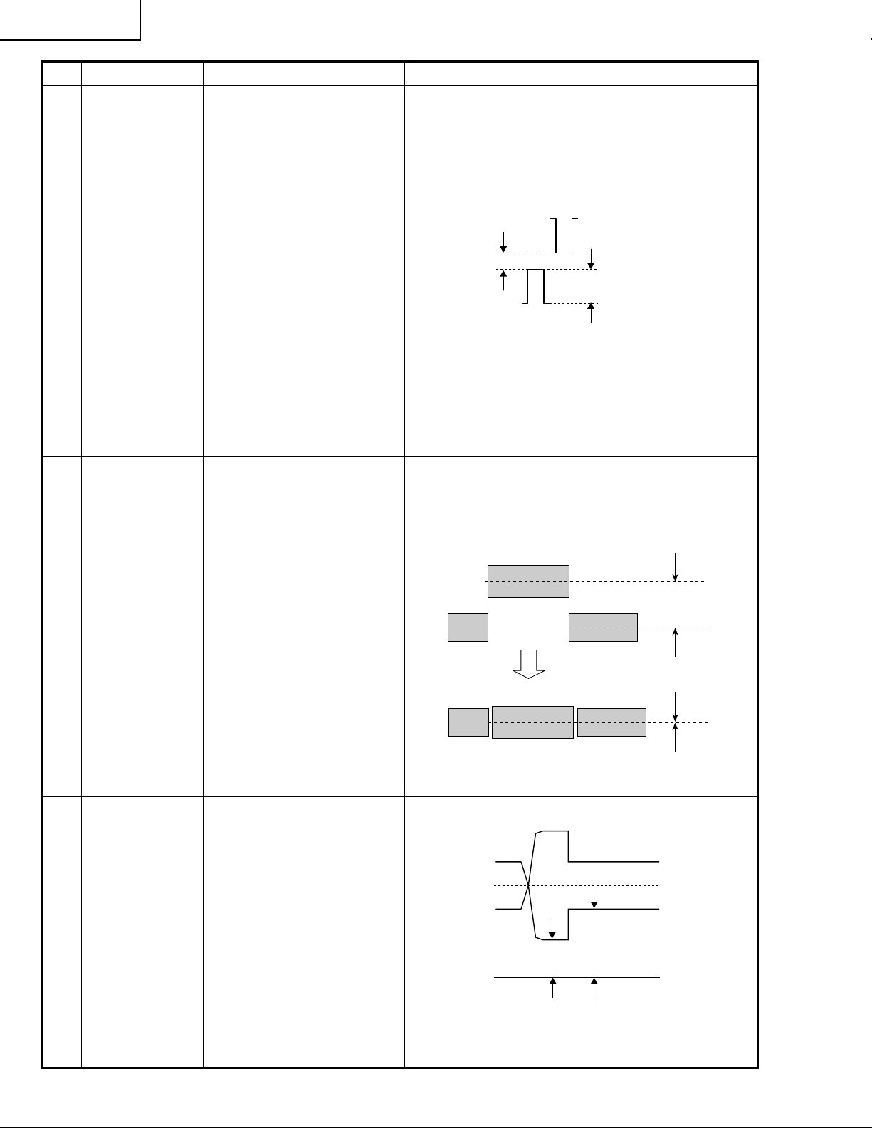
No. Adjusting point Adjusting conditions Adjusting procedure
7 RGB1 black
level signal
amplitude
8 Offset voltage
adjustment
1. Select the following group
and subjects for green.
Group : OUTPUT1
Subject : G1-BLK, G1-GAIN
Select the following subjects for red
Subject : R1-BLK, R1-GAIN
Select the following subjects for blue
Subject : B1-BLK, B1-GAIN
2. Make sure the process adjustment color bars appear
onscreen.
3. Connect the oscilloscope to
TP1201 (G) for green.
4. Similarly connect it to
TP1101 (R) for red and
TP1301 (B) for blue .
1. Feed the 50% gray pattern
signal.
2. Select the following subject.
Group : OUTPUT2
Subject : R-OFFSET
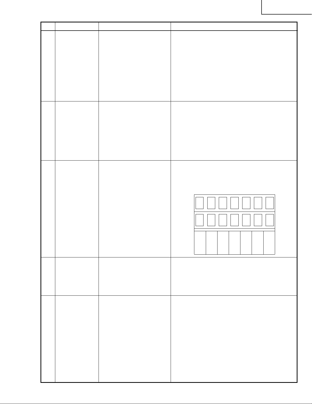
» Select G1-GAIN and using the control switch or the
button on the remote controller, adjust the signal
amplitude to 3.25 ±0.05 Vp-p.
» Select G1-BLK and using the control switch or the
button on the remote controller , adjust the white-towhite level to 2.5 ±0.1 Vp-p.
» Make the same adjustments for red and blue too.
2.5Vp-p
3.25Vp-p
* The G1-related adjustments are interlock ed with all
the other-color adjustments. When the G1-BLK le vel
is changed, therefore, the R1-BLK and B1-BLK v alues vary accordingly. When the G1-GAIN level is
changed, the R1-GAIN and B1-GAIN values vary
accordingly. First make the G adjustments and then
go for red and blue.
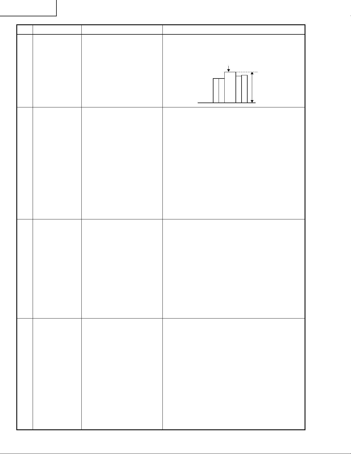
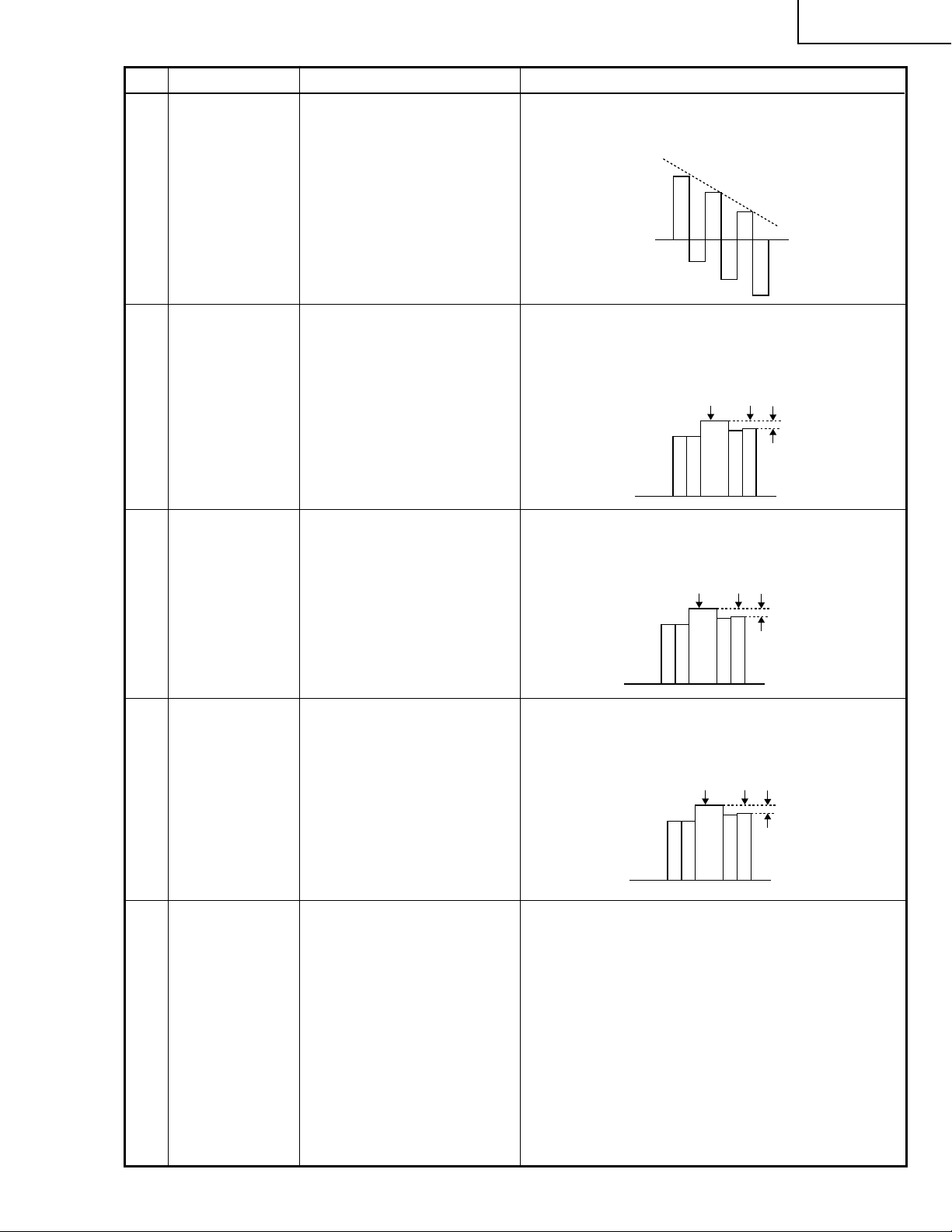
» Select the subject R-OFFSET. Make such adjust-
ment that the signal level at the top center 1 and
that at the bottom center 2 of the output wavef orm
on the instrument screen be the same.
Before adjustment
1
Select the subjects G-OFFSET and B-OFFSET for the
green and blue colors, respectively.
3. Connect the instrument to
TP1101 and TP1104 (R).
4. Connect the instrument to
TP1201 and TP1204(G) f or
green, and TP1301 and
TP1304(B) for blue.
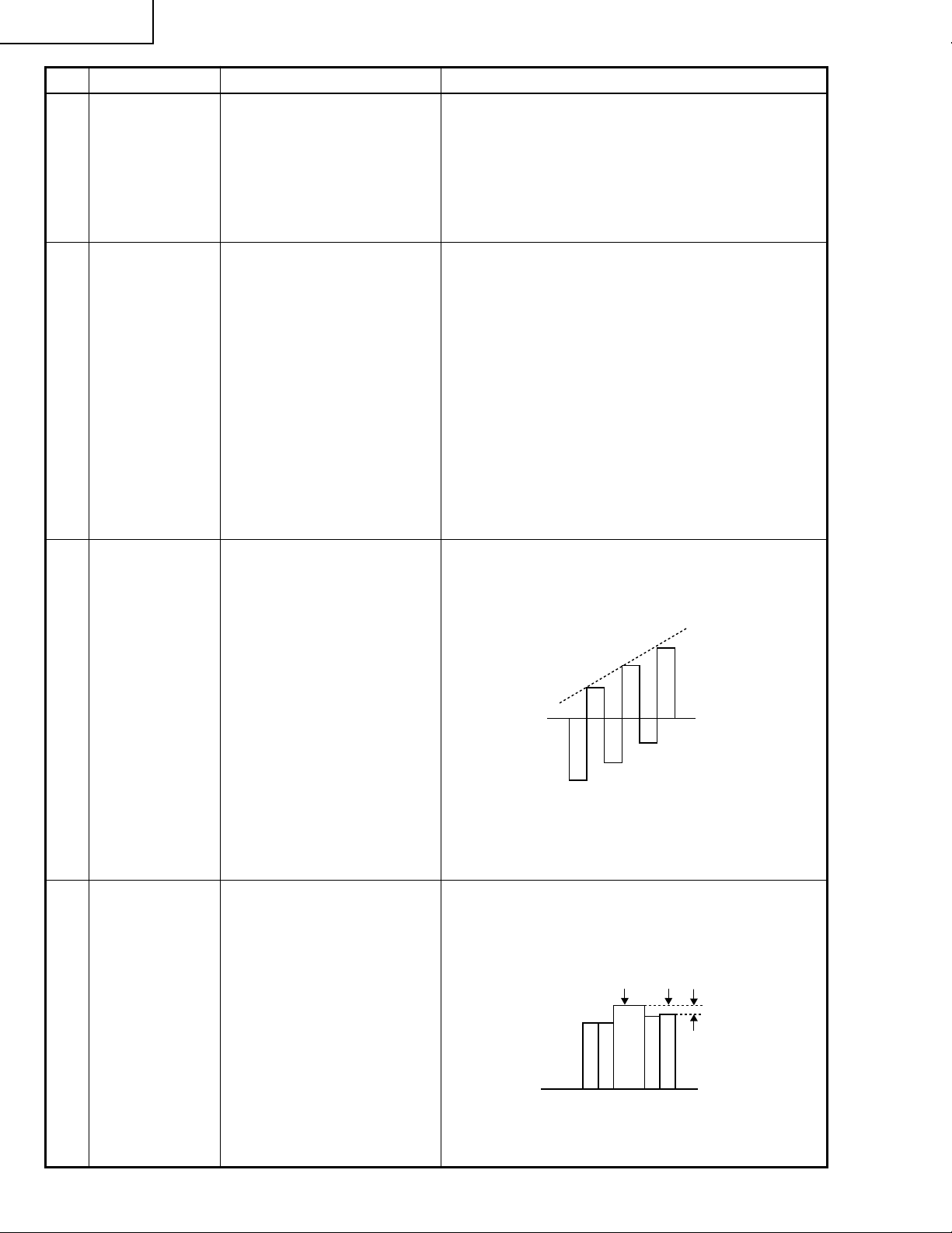
9 P SIGNAL 1. Connect the oscilloscope to
TP1102 for red.
TP1202 for green
TP1302 for blue.
2. Make the following choice:
Group : OUTPUT 2
Subject : PSIG-H
: PSIG-L
2
After adjustment
» Make the same adjustments for green and blue.
» Adjust the PSIG waveform to the one shown below.
PSIG
2.5V DC 5.0V DC
(Adjust with PSIG-L.)(Adjust with PSIG-H.)
GND
» For the green and blue colors, make sure their wave-
forms are similar to that of the red color.
26
Page 27
No. Adjusting point Adjusting conditions Adjusting procedure
XV-DW100U
10 Sample-and-
hold pulse
phase
RCK-PHASE
GCK-PHASE
BCK-PHASE
11 RGB counter-
voltage
adjustment
12 RGB gradation
reproduction
1. Feed the XGA mode 75-Hz
black signal.
2. Make the following choice:
Group : OUTPUT 3
Subject : SH-PHASE
(Have the standard level at
8.)
Fix the RCK-, GCK- and
BCK-PHASE settings all to
8.
1. Feed the black-and-red
(25%) stripe signal (XGA).
2. Make the following choice:
Group : OUTPUT 3
Subject : RC (R)
1. Feed the Inforcom gray
scale and color pattern signal.
2. Select the following group
and subject.
Group : OUTPUT1
Subject : G1-BLK
» Using the control switches or the remote controller
buttons, make sure that the “OUTPUT 3” characters are not blurry and there is no ghost image. If
such blur or ghost occurs, finely adjust the setting
in the range of 7~9.
» Using the control switches or the remote controller
buttons, adjust the data in order to minimize the
flicker.
» Make the same adjustment for BC (B) and GC (G).
» See if the image is equally adjusted at the center
and both sides of the screen. If not, readjust the
setting to have the image equal at right and left.
» Make sure the 251 (white) tone, shown below, ap-
pears noticeable. Be also sure that the 8 (black) tone
can be identified.
» If the white tone does not look as specified, finely
adjust the G1-BLK level.
4 8 12
13 RGB white
balance
14 Horizontal
center
1. Feed the 32-step gray scale
signal (XGA 60Hz).
Group : OUTPUT 1
Subject : R1-BLK (R)
B1-BLK (B)
1. Feed the NTSC monoscope pattern signal.
2. Group : VIDEO 2
Subject : N358-DLY (0)
N443-DLY (0)
PAL-DLY (0)
SECAM-DLY (0)
Make sure the settings are
as above.
3. Group : VIDEO 1
Subject : NTSC-H
249 251 253
» Adjust the R1-BLK and B1-BLK levels to achieve the
specified gradation balance.
(Adjust to the best point.)
» Using the control switches or the remote controller
buttons, adjust the data to hav e the same ov erscan.
27
Page 28
XV-DW100U
No. Adjusting point Adjusting conditions Adjusting procedure
15 Video picture
adjustment
16 Video offset 1. Feed the base-band (color
1. Feed the split color bar signal.
Group : VIDEO 1
Subject : PICTURE
2. Connect the oscilloscope
between pin (1) of P801
and GND.
bar) signal. (The ON-AIR
signal is not allowed because of its too much noise.)
2. Select the following group
and subjects.
Group : VIDEO2
Subject : VROS (R), VGOS
(G), VBOS (B)
3. Press the control switch or
the mute button on the remote controller. (Now the
gamma correction process
is set up.)
» Using the control switches or the remote controller
buttons, adjust the black-to-white (100%) level difference to 2.3 ±0.02 Vp-p.
100% White
2.3Vp-p
» Using the control switch or the button on the remote
controller, adjust the data so that the black signal
becomes bitless.
17 Video bright-
ness
18 Video AGC 1. Feed the split color bar sig-
1. Feed the base-band (color
bar) signal. (The ON-AIR
signal is not allowed because of its too much noise.)
2. Select the following group
and subject.
Group : VIDEO1
Subject : BRIGHT
3. Press the control s witch or the
mute button on the remote
controller. (Now the gamma
correction process is set up.)
nal.
2. Select the following group
and subject.
Group : VIDEO1
Subject : AGC
3. Connect the oscilloscope
between Pin (1) of P801
and GND.
» Using the control switch or the button on the remote
controller, adjust the data until the b lack signal drops
12 points below the bitless position.
» Using the control switch or the button on the remote
controller, adjust the data so that the 100% white
signal becomes bitless.
4. Press the control switch or the
mute button on the remote
controller. (Now the gamma
correction process is set up.)
28
Page 29
No. Adjusting point Adjusting conditions Adjusting procedure
XV-DW100U
19 Tint 1. Feed the split color bar sig-
nal.
Group : VIDEO 1
Subject : TINT
2. Connect the oscilloscope to
pin (4) of P801.
20 NTSC color
saturation level
1. Feed the split color bar signal.
Group : VIDEO 1
Subject : N-COLOR
2. Connect the oscilloscope to
pin (1) of P801.
21 PAL color
saturation level
1. Feed the P AL color bar signal.
Group : VIDEO 1
Subject : P-COLOR
» Using the control switches or the remote controller
buttons, adjust the data to have the -(B-Y) waveform downhill straight.
» Using the control switches or the remote controller
buttons, adjust the difference betw een the 100% white
portion and the red portion to 0.30 ±0.02 Vp-p.
(same as 100% white)
100% White Red
» Using the control switches or the remote controller
buttons, adjust the difference betw een the 100% white
portion and the red portion to 0.36 ±0.02 Vp-p.
100% White Red
22 SECAM color
saturation level
23 Video input
panel signal
amplitude
2. Connect the oscilloscope to
pin (1) of P801.
1. Feed the SECAM color bar
signal.
Group : VIDEO 1
Subject : S-COLOR
2. Connect the oscilloscope to
pin (1) of P801.
1. Feed the NTSC 10-step signal.
2. Select the following group
and subjects.
Group : VIODE2
Subject : R1-GAIN
B1-GAIN
3. Connect the oscilloscope to
TP1101 (R) and TP1201
(G).
4. Similarly connect it to
TP1301 (B) and TP1201
(G) for blue.
» Using the control switches or the remote controller
buttons, adjust the difference betw een the 100% white
portion and the red portion to 0.50 ±0.02 Vp-p.
100% White Red
» Select R1-GAIN and adjust the data so that the R
signal amplitude and the G signal amplitude are the
same.
» Make the same adjustment for blue too.
29
Page 30
XV-DW100U
No. Adjusting point Adjusting conditions Adjusting procedure
24 Video white
balance
25 DVD Contrast 1. Feed the 100% color bar
26 DVD Tint 1. Feed the 100% color bar sig-
1. Feed the NTSC monoscope pattern signal
Group : VIDEO 2
Subject : R1-BLK
B1-BLK
signal (480I component signal) to the G(Y) input terminal of BNC connector.
2. Select the following subject.
Group : DVD
Subject : CONTRAST
nal (480I component signal)
to the Y, Pb and Pr input terminals of BNC connector.
The sync signal alone is sent
for the Y signal.
» Using the control switches or the remote controller
buttons, adjust so that the entire screen looks ev enly
colorless.
» Using the control switch or the button on the remote
controller, adjust the data so that the 100% white
signal becomes bitless.
» Using the control switch or the button on the remote
controller, adjust the B-Y wa vef orm to form a straight
slope.
2. Select the following subject.
Group : DVD
Subject : TINT
3. Connect the oscilloscope to
pin (2) of P803.
27 DVD Color 1. Feed the 100% color bar
signal (480I component signal) to the G(Y) input terminal of BNC connector.
2. Select the f ollowing subject.
Group : DVD
Subject : COLOR
3. Connect the oscilloscope to
pin (1) of P803.
» Using the control switches or the remote controller
buttons, adjust the diff erence between the 100% white
portion and the red portion to 0.10 ±0.02 Vp-p.
100% White Red
30
Page 31

No. Adjusting point Adjusting conditions Adjusting procedure
XV-DW100U
28 DVD input panel
signal amplitude
29 DVD white
balance
1. Feed the 10-step signal to
the G(Y) input terminal of
BNC connector.
2. Select the following group
and subjects.
Group : DVD
Subject : R1-GAIN
B1-GAIN
3. Connect the oscilloscope to
TP1101 (R) and TP1201
(G).
4. Similarly connect it to
TP1301 (B) and TP1201
(G) for blue.
1. Feed the NTSC monoscope signal to the G(Y) input terminal of BNC connector.
» Select R1-GAIN and adjust the data so that the R
signal amplitude and the G signal amplitude are the
same.
» Make the same adjustment for blue too.
» Using the control switch or the button on the remote
controller, adjust the data so that the white balance
is the same as that of the sample unit.
30 Color
irregularity
correction
position
31 Color
irregularity
correction gain
(in case of
colorirregularity)
2. Select the following group
and subjects.
Group : DVD
Subject : R1-BLK, B1-BLK
1. Feed the gray-only RGB
color signal. (XGA 60Hz)
2. Find the color irregularity
position on the screen.
3. Group : NOKO
Subject : NOKO-RL
1. Feed the gray-only RGB
color signal. (XGA 60Hz)
» If the color is irregular, adjust the NOKO-RL data.
Set it to R for the right-hand color irregularity and to
L for the left-hand one.
» If there is no color irregularity , turn off the saw-tooth
correction using SW4201.
» Adjust R4215 to minimize the right-hand and left-
hand color irregularity.
32 Automatic color
correction
1. Using the color correction
system (DCCS100), make
corrections of the colors.
» Make sure there is no noticeable color irregularity
left on the screen.
31
Page 32

XV-DW100U
No. Adjusting point Adjusting conditions Adjusting procedure
33 White balance
check and
readjustment
34 Color system
performance
check
35 Video system
performance
check
1. Have the following adjustment conditions: RGB input
level at 13, video input le vel
at 24 and DVD input level
at 29.
2. DTV input:
Feed the 720P SMPTE
(color difference) signal.
3. If out of spec, select and readjust the following subjects.
Group : DTV
Subject : R-BRIGHT
B-BRIGHT
1. Receive the color bar signal.
1. Receive the monoscope
pattern signal.
» Make sure that the white balance is in the best set-
ting. Readjust the RGB input, video input and DVD
input in this order, if required.
» In the process mode and select L1. Chec k the color
and tint.
» In the process mode and select L2. Check the pic-
ture, brightness and sharpness.
36 Audio system
performance
check
37 RGB
performance
check
38 Off-timer
performance
check
39 Thermistor
performance
check
40 Automatic
synchronization
41 Keystone
correction
performance
check
» In the process mode nad select L3. Check the bass,
treble and balance.
1. Receive the RGB signal. » In the process mode and select L4. Check the pic-
ture, brightness, red, blue, clock, phase, horizontal
position, and vertical position.
» In the process mode and select OFF. Make sure that
the off-timer starts with “5” (minutes), counts down
each minute in 1 second, and turns off the set at “0”.
1. Heat the thermistor using a
» Make sure the “TEMP” is displayed.
dryer.
1. Receive the PHASE check
pattern signal.
» Call the VGA/SV GA/XGA mode and make sure that
the clock, phase, horizontal and vertical positions
can be automatically adjusted.
» Make sure the keystone correction functions well.
32
» Make the following settings.42 Factory settings
Process
adjustment
Remote controller
setting
S4 “Factory setting 4”
Page 33

XV-DW100U
ADJUSTING THE PC INTERFACE (CPCi-0035CE03. PC I/F Unit)
1.Setting the oscilloscope
Set the range to DC 1 V/div and 5µ/div.
2.Connecting the PC Interface
1) Fit the PC I/F in position and make sure the CON2, CON3 and CON4 connectors are all tight in place.
2) Connect the cable between the ANALOG OUTPUT (PC computer) and the DSUB connector (INPUT1 of the
proejctor).
3) Set the projector’s input selector to the INPUT1 position. Make sure the Dsub/BNC selector is at the Dsub
position.
4) Set the PC computer in the XGA mode (1024 x 768, 60 Hz, 32-step scale). Adjust the output amplitude to
700 mVp-p (terminated with 75 ohms) for the black-to-white portions.
5) Turn on the power.
3.Adjusting and checking the levels
1) Press the S5001 switch to call the process mode.
2) Set the SH-PHASE data on the OUTPUT3 menu to 8. (Make sure the OSD characters look clear and crisp.)
3) Make sure the GAIN data on the A/D menu is 155.
4) Adjust the M-BRIGHT data of OUTPUT2 until the green signal’s black level becomes bitless.
5) Adjust the R-BRIGHT data of A/D until the red signal’s black level becomes bitless.
6) Adjust the B-BRIGHT data of A/D until the blue signal’s black level becomes bitless.
4.Adjust the DTV
1) Set the switch to the BNC input terminal of INPUT1.
2) Using the control switch or the button on the remote controller, set the signal type to component.
3) Feed the 480P Y signal to the G(Y) input terminal. Keep the R (Pr) and B (Pb) terminals out of any input.
4) Adjust the B-BRIGHT data of DTV until the red signal’s black level becomes bitless.
5) Adjust the R-BRIGHT data of DTV until the blue signal’s black level becomes bitless.
6) Press the S5001 switch to exit the process mode.
33
Page 34

XV-DW100U
TROUBLE SHOOTING TABLE
Checking the PWB performance
Video input in trouble
Go to "Checking the video unit
circuit".
RGB input in trouble
Feed test pattern signal from
PC.
Is specified cable connected
between PC and projector?
Yes
Is supply voltage as specified?
Yes
Does image appear?
Yes
Go to "Trouble shooting table
for PC I/F unit ".
Through-output in trouble
Through-output circuit in
trouble.
No
Use specified cable.
No
Power circuit in trouble.
No
Check the connectors, starting
from the PC input circuit.
Remote control in trouble
Go to "Checking the remote
control".
34
Page 35

TROUBLE SHOOTING TABLE (Continued)
Checking the video system
XV-DW100U
Is the lamp on?
Is specified voltage fed to EA
connectors?
Are there signal inputs at pins (7), (9)
and (25) of SC401?
Are there signal outputs at pins (7) of
IC6010 and (5) of IC6009?
Yes
Go to "Checking IC801
(RGB signal output circuit)".
No
Yes
No
Yes
No
Yes
No
Check IC6001, IC6010,
IC6009 and their peripheral
circuits as well as switching
circuit.
Go to "Lamp fails to light-up".
Check the power circuit and its parts.
Are there signals at pin (4) of IC6011?
Yes
Check the video unit circuit
(IC4501 and IC4001 and its
peripheral circuits).
No
Check the oscillation circuit
of IC6011, and their
peripheral circuits.
Checking the video unit circuit
Is there video signal output at pin (7)
of IC401?
Yes
Is there video signal input at IC4001?
Yes
Are there signal outputs at pins (6)
and (8) of IC4001?
Yes
Check the low-pass and buffer circuits
of Q6002 thru Q6008. Is the signal as
specified?
Yes
Go to "Checking IC801 (RGB signal
output circuit)".
No
Check the IC401 selector switch,
terminal voltage and input circuit.
No
Check the low-pass and buffer
circuits of Q4002 thru Q4012.
No
Check IC4001 and its peripheral
circuits (bias).
No
Check Q4007 thru Q4009 and their
peripheral circuits.
35
Page 36

XV-DW100U
TROUBLE SHOOTING TABLE (Continued)
Checking IC801 (RGB signal output circuit)
No
Are there RGB output waveforms at
pins (31), (32) and (33) of IC801?
Go to "No colour or unusual tone",
"No Y signal" or "Out of sync".
Are there output waveforms at pin
(1) of IC6803, IC6804, IC6805?
Are A/D outputs of IC6805, IC6806
and IC6806 as specified?
Go to "Trouble shooting table for PC
I/F unit".
Yes
Yes
Yes
Checking the chroma and Y signals of IC801
No
Check the data transfer and other
performance at pins (17) and (18) of
video IC801.
No
Check IC6802, IC6803, IC6804,
IC6805 and their peripheral circuits.
No
Check the CLK IC6805, IC6806,
IC6807 and their peripheral circuits.
(RGB signal output)
Are there signal inputs at pins (7), (9)
and (25) of SC401?
Yes
Are there output waveforms at pins
(7) of IC6010 (chroma signal) and
(5), (Y signal)of IC6009?
Yes
Are there signal inputs at pins (20)
(chroma signal) and (21) (Y signal)
of IC801?
Yes
Go to "Checking IC801 (RGB signal
output circuit)".
No
Go to "Checking the video unit
circuit".
No
Check the IC6009 and IC6010
switching and their peripheral circuits. If
there is no signal at pins (1) of IC6010
and pin (16) of IC6009 check 3-D noise
reduction circuit (IC8001).
No
Check IC801 and its peripheral
circuits.
Check IC806 (3-D noise reduction
circuit) and its peripheral circuits.
36
Page 37

TROUBLE SHOOTING TABLE (Continued)
Checking IC806 (3-D noise reduction circuit)
and its peripheral circuits
XV-DW100U
Are there signal inputs at pins (40)
(Y signal) and (45)(chroma signal) of
IC8001?
Yes
Are there signal outputs at pins (55)
(Y signal) and (51)(chroma signal) of
IC8001?
Yes
Are there signal outputs at the
emitters of Q6008 (Y signal) and
Q6009 (chroma signal)?
Yes
Check IC6009, IC6010 and IC801
(RGB signal output circuit).
No
Check the buffer circuit of Q6004 thru
Q6006 as well as Q6001 thru Q6003.
No
Check IC8003, IC8002 (memory) and
their peripheral circuits.
No
Check the low-pass circuit around
Q6008, Q6007 and Q6009.
No color or unusual tone (NTSC, PAL)
Is there chroma signal input at pin
(20) of IC801?
No
Yes
Are there signal outputs at pins
(46)(R-Y) and (45)(B-Y) of IC801?
Yes
Check IC803, IC814 and their
peripheral circuits.
Go back to the signal processing
block.
No
Check the oscillation of X801 and
X802, and their peripheral circuits.
37
Page 38

XV-DW100U
TROUBLE SHOOTING TABLE (Continued)
No or unusual Y signal
Is there Y signal input at pin (21) of
IC801?
Yes
Is there Y signal output at pin (40) of
IC801?
Yes
Is there Y signal output at pin (17) of
IC803?
Yes
Check IC803 and its peripheral
circuits.
No
Go back to the signal processing
block.
No
Check IC801 and its peripheral
circuits.
No
Check IC803 and its peripheral
circuits as well as IC805 (AGC).
No or unusual horizontal sync
Is there horizontal sync pulse output
at pin (56) of IC801?
Yes
Is there horizontal sync pulse output
at pin (9) of IC803?
No
Check IC801 and its peripheral
circuits.
No
Yes
Check IC604 and its peripheral
circuits, and go to "Trouble shooting
table for PC I/F unit".
No or unusual vertical sync
Is there vertical sync pulse output at
pin (4) of IC801?
Yes
Check IC2405 and its peripheral
circuits, and go to "Trouble shooting
table for PC I/F unit".
No
Check the pulse shaping circuit of
IC802 and IC803.
Check IC801 and its peripheral
circuits.
38
Page 39

TROUBLE SHOOTING TABLE (Continued)
Checking the output PWB unit
XV-DW100U
If there is no signal at P801
and P802, go to the video
system block.
If there is no signal at SC8404
and SC8405, go to "Trouble
shooting table for PC I/F unit".
Are there signal inputs at
SC1404, SC1405, SC1501 and
SC1502?
Are voltages applied to EA
connectors and SC8404,
SC8405 and SC8502?
Yes
Are there signal outputs at
pins (17) of IC2102, IC2202,
IC2302?
Yes
Are there signal inputs at pin
(47) of IC1101, IC1102,
IC1201, IC1202, IC1301 and
IC1302?
Yes
Are there signal outputs at pins
(17), (19), (21), (27), (29) and
(31) of IC1101, IC1102,
IC1201, IC1202, IC1301 and
IC1302?
Yes
NoNo
If there is no signal at EA
connector or SC8404, SC8405
and SC8502, go to Checking
the power unitblock.
No
Check IC2101, IC2202,
IC2302 and their peripheral
circuits.
No
Check IC2102, IC2202,
IC2302 and their peripheral
circuits.
No
Check IC1101,IC1201,IC1301
and their peripheral circuits.
If there is no signal input at
pins (1) and (31) of SC1101,
SC1102 and SC1103, check
the switching circuit and
amplifier circuit of IC1101,
IC1201, IC1301, IC1102,
IC1202, IC1302 and their
peripheral circuits.
No
Are there signal inputs at
SC1101, SC1201 and
SC1301?
Check the R, G and B panels.
Yes
Yes
No
If there is no signal input at
pins (15) and (30) of
SC1101, SC1102 and
SC1103, check IC1603,
IC1601 and their
peripheral circuits.
Check IC1611, IC1612,
IC1613, IC1615 and their
peripheral circuits.
39
Page 40

XV-DW100U
TROUBLE SHOOTING TABLE (Continued)
No audio output
Are there audio signal inputs at pins
(2) and (23) of IC1301?
Are there audio signal outputs at pins
(1) and (2) of P301?
Are there audio signal outputs at pin
(6) of IC302?
If the voltage at pin (7) of IC302 is not
as specified, check Q7082, Q7081
and their peripheral circuits.
No
Yes
No
Yes
No
Yes
Check IC302 and its peripheral
circuits, and the SP connectors and
speakers.
Check the input, the switching circuit
of IC441 and IC442, and their
peripheral circuit.
Check the IC1411 control voltage,and
its peripheral circuits.
Check IC302 and its peripheral
circuits.
40
Page 41

TROUBLE SHOOTING TABLE (Continued)
Checkig the Power Unit
There is no voltage output at
EA connector.
No
XV-DW100U
Replace.
Is EA connector disconnected
or loose?
Is AC voltage (85-264V)
applied across the PA
connector?
Yes
Is TF751 broken?
Is R727 broken?
Replace R727 or Q701.
No
Yes
No
Yes
Yes
Reconnect the EA connector.
No
Replace F791.
No
There is a short-circuit along
the EA output line. Using a
tester, check the resistance
between each voltage line and
the ground.
41
Page 42

XV-DW100U
TROUBLE SHOOTING TABLE (Continued)
Power on
Is the right input selected?
Yes
Are the PC, video and LCP cables as
specified and properly connected?
Yes
With the contrast control at maximum,
does the image appear?
No
Is the voltage at CON3 (P8502)
connector as specified?
Yes
Hook up a personal computer.
Does the image appear?
No
Select the right input with remote
control.
No
Use the right cables or reconnect the
cables.
Yes
Readjust the video system.
No
Power circuit faulty.
Yes
Is the image as specified?
Is the image's color as specified?
A
Does the on-screen display function?
Does the remote control function?
End
No
No
No
No
No
Go to "Checking the clock circuit and
its peripheral circuits".
Yes
Check the sync signal circuit and its
peripheral circuits.
Yes
Check the video circuit and its
peripheral circuits.
Yes
Go to "Checking the OSD circuit and
its peripheral circuits".
Yes
Go to "Checking the remote control".
42
Page 43

TROUBLE SHOOTING TABLE (Continued)
Is the lamp out of socket?
Yes
Reconnect the
lamp into socket.
No
Replace the
lamp.
Lamp fails to light-up
Turn on the power switch. Is
Yes
discharging sound heard from
the lamp?
No
Is the ballast cooling fan
running?
Yes
XV-DW100U
No
Check the power circuit.
Replace the ballast.
Is DC 360V voltage applied
between PL connector pins?
Yes
Is 3.5V or higher voltage
applied between pins (1) and
(3) of ballast's D connector?
Is power EA connector
disconnected?
Yes
Reconnect the
connector into socket.
No
Yes
No
No
Check the
microcomputer circuit.
43
Page 44

XV-DW100U
TROUBLE SHOOTING TABLE FOR PC I/F UNIT-1
Checking the clock circuit and its peripheral circuits
Is X8001 (6MHz) oscillating?
Yes
Is X8002 (32.768kHz) oscillating?
Yes
Is X8003 (1.84MHz) oscillating?
Yes
Is X8004 (22.165MHz) oscillating?
Yes
Is X8005 (16.25MHz) oscillating?
Yes
Does pin (162) of IC8001 function?
Yes
Check the sync signal circuit and its
peripheral circuits.
No
Is sync signal of separate type?
Yes
Are there signals at TP4 and TP5?
Yes
No
No
No
No
No
No
No
X8001 or its peripheral part faulty.
X8002 or its peripheral part faulty.
X8003 or its peripheral part faulty.
X8004 or its peripheral part faulty.
X8005 or its peripheral part faulty.
IC8001 or its peripheral circuit faulty.
Output PWB defective.
No
Is sync signal of sync-on-green type?
Yes
Is there signal at Pin (7) of IC8036?
Yes
Are there signals at Pins (149) (TL34)
and (150) (TL35) of IC8020?
Yes
No
Is the input lower in resolution than
XGA or video?
Yes
Are there signals at Pins (26) (TL43),
(28) (TL41) and (29) (TL42) of IC8020?
Yes
Are there signals at Pins (14), (16)
and (18) of IC8405?
Yes
Go to "Checking the PLL circuit and
its peripheral circuits".
No
No
No
No
IC8023, IC8034. IC8036 or peripheral
component defective.
IC8025 or peripheral component
defective.
IC8020 or peripheral component
defective.
IC8029 or peripheral component
defective.
44
Page 45

TROUBLE SHOOTING TABLE FOR PC I/F UNIT-2
Checking the PLL circuit and its peripheral circuits
XV-DW100U
Are there signals at pins (6) and (22)
of IC8015?
Yes
Is there signal at pin (18) and (19) of
IC8015?
Yes
Check the video circuit and its
peripheral circuits.
Is image as specified at resolution
below XGA level?
Yes
Hook up a video system. Is the
display as specified?
Yes
A
No
IC8025 or its peripheral circuit faulty.
No
IC8015 or its peripheral circuit faulty.
No
Check the VGA video circuit and its
peripheral circuits.
No
Check the video system's video
circuit and its peripheral circuits.
45
Page 46

XV-DW100U
IC8067 or its peripheral circuit faulty.
TROUBLE SHOOTING TABLE FOR PC I/F UNIT-3
Checking the VGA's
red video circuit and
its peripheral
circuits
No
Output PWB faulty.
Is there signal at pin (6) of IC8067?
No
Is there signal at the base of Q8009?
Yes
Yes
Q8009 or there peripheral circuit
faulty.
IC8011 or its peripheral circuit faulty.
IC8025 or its peripheral circuit faulty.
IC8020 or its peripheral circuit faulty.
Are there signals at pins (1) thru (10)
of IC8051?
Yes
IC8029 or its peripheral circuit faulty.
No
No
Is there signal at pin (6) of IC8011?
Yes
No
Are there signals at pins (21) thru (27)
and (33) thru (40) of IC8011?
Yes
No
Are there signals at pins (112) thru
(119) of IC8020?
Yes
No
Are there signals at pins (69) thru (73)
and (189) thru (192) of IC8020?
Yes
B
Are there signals at pins (9) and (10) of
P8405 connector?
Yes
IC8051 or its peripheral circuit faulty.
P8405 connector or output PWB
faulty.
No
46
Check the video
system's red video
circuit and its
peripheral circuits
No
Are there signals at pins (35) thru (42)
of P8404 connector?
Yes
B
Page 47

TROUBLE SHOOTING TABLE FOR PC I/F UNIT-4
Checking the VGA's
green video circuit
and its peripheral
circuits
No
Output PWB faulty.
IC8066 or its peripheral circuit faulty.
Q8007 or there peripheral circuit faulty.
Is there signal at pin (6) of IC8066?
Yes
No
Is there signal at the base of Q8007?
Yes
No
Is there signal at pin (6) of IC8010?
XV-DW100U
IC8010 or its peripheral circuit faulty.
IC8025 or its peripheral circuit faulty.
IC8020 or its peripheral circuit faulty.
Are there signals at pins (11) thru (20)
of IC8051?
Yes
IC8029 or its perpheral circuit faulty.
Are there signals at pins (5) and (6) of
P8405 connector?
No
No
Yes
No
Are there signals at pins (21) thru (27)
and (33) thru (40) of IC8010?
Yes
No
Are there signals at pins (165) thru
(177) of IC8020?
Yes
No
Are there signals at pins (178) thru
(187) of IC8020?
Yes
Check the video
system's green
C
Yes
IC8051 or its peripheral circuit faulty.
P8405 connector or output PWB
faulty.
47
video circuit and its
peripheral circuits
No
Are there signals at pins (25) thru (32)
of P8404 connector?
Yes
C
Page 48

XV-DW100U
IC8065 or its peripheral circuit faulty.
TROUBLE SHOOTING TABLE FOR PC I/F UNIT-5
Checking the VGA's
blue video circuit
and its peripheral
circuits
No
Output PWB faulty.
Is there signal at pin (6) of IC8065?
Yes
No
Is there signal at the base of Q8005?
Yes
Q8004 and Q8005 or there peripheral
circuit faulty.
IC8009 or its peripheral circuit faulty.
IC8020 or its peripheral circuit faulty.
IC8020 or its peripheral circuit faulty.
Are there signal at pins (21) thru (30)
of IC8051?
Yes
IC8029 or its peripheral circuit faulty.
No
No
Is there signal at pin (6) of IC8009?
Yes
No
Are there signals at pins (21) thru (27)
and (33) thru (40) of IC8009?
Yes
No
Are there signals at pins (85) thru (93)
of IC8020?
Yes
No
Are there signals at pins (74) thru (83)
of IC8020?
Yes
D
Are there signal at pins (1) and (2) of
P8405 connector?
Yes
IC8051 or its peripheral circuit faulty.
P8405 connector or output PWB
faulty.
No
48
Check the video
system's blue video
circuit and its
peripheral circuits.
No
Are there signals at pins (15) thru (22)
of P8404 connector?
Yes
D
Page 49

TROUBLE SHOOTING TABLE FOR PC I/F UNIT-6
Checking the OSD circuit and its peripheral circuits
Display OSD on the screen.
Yes
XV-DW100U
Are there signals at pins (56), (58),
(71) and (72) of IC8048
(TL54,TL53,TL52 and TL51)?
Yes
Are there signals at pins (12), (14)
thru (17) and (20) of IC8046?
Yes
Are there signals at pins (23) thru
(42) of IC8046?
Yes
IC8048 or its peripheral circuit faulty.
No
IC8029 or its peripheral circuit faulty.
No
IC8048 or its peripheral circuit faulty.
No
IC8046 or its peripheral circuit faulty.
Checking the remote control
Run the remote control. Are there
signals at pin (47) of P8405 connector
(or R294)?
Yes
No
Output PWB faulty.
Using remote controller, is there
signal at pin (8) of IC8001?
Yes
IC8001 circuit faulty.
No
IC8006 circuit faulty.
49
Page 50

CHASSIS LAYOUT
XV-DW100U
OUTPUT UNIT
H
DUNTKA111DE01
PC I/F UNIT
CPCI-0035CE03
INLET UNIT
G
F
RUNTK0656CEZZ
SIGNAL UNIT
E
DUNTK9921DE05
POWER UNIT
RDENC0287CEZZ
D
R/C RECEIVER UNIT
DUNTKA113DE01
C
TERMINAL UNIT
DUNTK9923DE05
B
FILTER UNIT
RDENC0288CEZZ
BALLAST UNIT
RDENC0286CEZZ
S-OUT UNIT
DUNTKA112DE01
A
121110987654321
50
51
Page 51

BLOCK DIAGRAM
H
G
F
XV-DW100U
E
D
C
B
A
121110987654321
52
53
Page 52

OVERALL WIRING DIARGAM
H
G
F
XV-DW100U
E
D
C
B
A
121110987654321
54
55
Page 53

XV-DW100U
H
G
DESCRIPTION OF
SCHEMATIC DIAGRAM
VOLTAGE MEASUREMENT CONDITION:
1. Voltages at test points are measured at the
supply voltage of AC 120V. Signals are fed by a
color bar signal generator for servicing purpose and
the above voltages are measured with a 20k ohm/V
tester.
WAVEFORM MEASUREMENT CONDITION:
1. Wav eforms at test points are observed at the supply
voltage of AC 120V. Signals are fed by a color bar
signal generator for servicing purpose.
F
INDICATION OF RESISTOR & CAPACITOR:
RESISTOR
1. The unit of resistance “Ω” is omitted.
(K=kΩ=1000 Ω, M=MΩ).
2. All resistors are ± 5%, unless otherwise noted.
(J= ± 5%, F= ± 1%, D= ± 0.5%)
E
D
C
3. All resistors are 1/10W, unless otherwise noted.
4. All resistors are Carbon type, unless otherwise
noted.
C : Solid
S : Oxide Film T : Special
N : Metal Coating
CAPACITOR
1. All capacitors are µF, unless otherwise noted.
(P=pF=µµF).
2. All capacitors are 50V, unless otherwise noted.
3. All capacitors are Ceramic type, unless otherwise
noted.
(ML): Mylar (TA): Tantalum
(PF): Polypro Film (ST): Styrol
CAUTION:
This circuit diagram is original one, therefore there may be a
slight difference from yours.
W
: Cement
SAFETY NOTES:
1. DISCONNECT THE AC PLUG FROM THE AC
B
OUTLET BEFORE REPLACEING PARTS.
2. SEMICONDUCTOR HEAT SINKS SHOULD BE
REGARDED AS POTENTIAL SHOCK HAZARDS
WHEN THE CHASSIS IS OPERATING.
IMPORTANT SAFETY NOTICE:
PARTS MARKED WITH “å” ( ) ARE
A
IMPORTANT FOR MAINTAINING THE SAFETY OF
THE SET. BE SURE TO REPLACE THESE PARTS
WITH SPECIFIED ONES FOR MAINTAINING THE
SAFETY AND PERFORMANCE OF THE SET.
87109654321
56
Page 54

WAVEFORMS
XV-DW100U
1 SC1101 7-pin
(RSIG5)
H : 10µsec/div
V : 2V/div
5 SC1301 7-pin
(BSIG5)
H : 10µsec/div
V : 2V/div
2 SC1101 8-pin
(RSIG6)
H : 10µsec/div
V : 2V/div
6 SC1301 8-pin
(BSIG6)
H : 10µsec/div
V : 2V/div
3 SC1201 7-pin
(GSIG5)
H : 10µsec/div
V : 2V/div
7 P803 1-pin
(R)
H : 10µsec/div
V : 0.5V/div
4 SC1201 8-pin
(GSIG6)
H : 10µsec/div
V : 2V/div
8 SC801 5-pin
(G)
H : 20µsec/div
V : 0.5V/div
9 P803 4-pin
(B-Y)
H : 20µsec/div
V : 1V/div
e IC801 20-pin
(CHROMA signal)
H : 10µsec/div
V : 0.2V/div
0 SC801 8-pin
(H-OUT)
H : 20µsec/div
V : 1V/div
q Q6012 Emitter
57
(4FSC)
H : 50µsec/div
V : 0.5V/div
w IC801 21-pin
(Y-signal)
H : 10µsec/div
V : 0.2V/div
1716 1918151413121110
Page 55

XV-DW100U
Ë
SIGNAL UNIT-1/4
H
G
F
E
D
C
B
A
121110987654321
58
59
Page 56

XV-DW100U
Ë
SIGNAL UNIT-2/4
H
G
F
E
D
C
B
A
121110987654321
60
61
Page 57

XV-DW100U
Ë
SIGNAL UNIT-3/4
H
G
F
E
D
C
B
A
121110987654321
62
63
Page 58

XV-DW100U
Ë
SIGNAL UNIT-4/4
H
G
F
E
D
C
B
A
121110987654321
64
65
Page 59

XV-DW100U
Ë
OUTPUT UNIT-1/7
H
G
F
E
D
C
B
A
121110987654321
66
67
Page 60

XV-DW100U
Ë
OUTPUT UNIT-2/7
H
G
F
E
D
C
B
A
121110987654321
68
69
Page 61

XV-DW100U
Ë
OUTPUT UNIT-3/7
H
G
F
E
D
C
B
A
121110987654321
70
71
Page 62

XV-DW100U
Ë
OUTPUT UNIT-4/7
H
G
F
E
D
C
B
A
121110987654321
72
73
Page 63

XV-DW100U
Ë
OUTPUT UNIT-5/7
H
G
F
E
D
C
B
A
121110987654321
74
75
Page 64

XV-DW100U
Ë
OUTPUT UNIT-6/7
H
G
F
E
D
C
B
A
121110987654321
76
77
Page 65

XV-DW100U
Ë
OUTPUT UNIT-7/7
H
G
F
E
D
C
B
A
121110987654321
78
79
Page 66

XV-DW100U
Ë
TERMINAL UNIT-1/2
H
G
F
E
D
C
B
A
121110987654321
80
81
Page 67

XV-DW100U
Ë
TERMINAL UNIT-2/2
H
G
F
E
D
C
B
A
121110987654321
82
83
Page 68

XV-DW100U
Ë
SOUND OUT UNIT
H
H
G
G
F
F
E
E
D
D
C
C
B
B
A
A
87109654321
654321
84
Page 69

XV-DW100U
Ë
R/C RECEIVER UNIT
H
G
F
E
D
C
B
A
1716 1918151413121110
654321
85
Page 70

XV-DW100U
Ë
OPERATION KEY UNIT
H
G
F
E
D
C
B
A
121110987654321
86
87
Page 71

XV-DW100U
Ë
FILTER AND INLET UNIT
H
G
F
E
D
C
B
A
121110987654321
88
89
Page 72

XV-DW100U
Ë
POWER UNIT
H
G
F
E
D
C
B
A
121110987654321
90
91
Page 73

XV-DW100U
Ë
PC I/F UNIT-1/8
H
G
F
E
D
C
B
A
121110987654321
92
93
Page 74

XV-DW100U
Ë
PC I/F UNIT-2/8
H
G
F
E
D
C
B
A
121110987654321
94
95
Page 75

XV-DW100U
Ë
PC I/F UNIT-3/8
H
G
F
E
D
C
B
A
121110987654321
96
97
Page 76
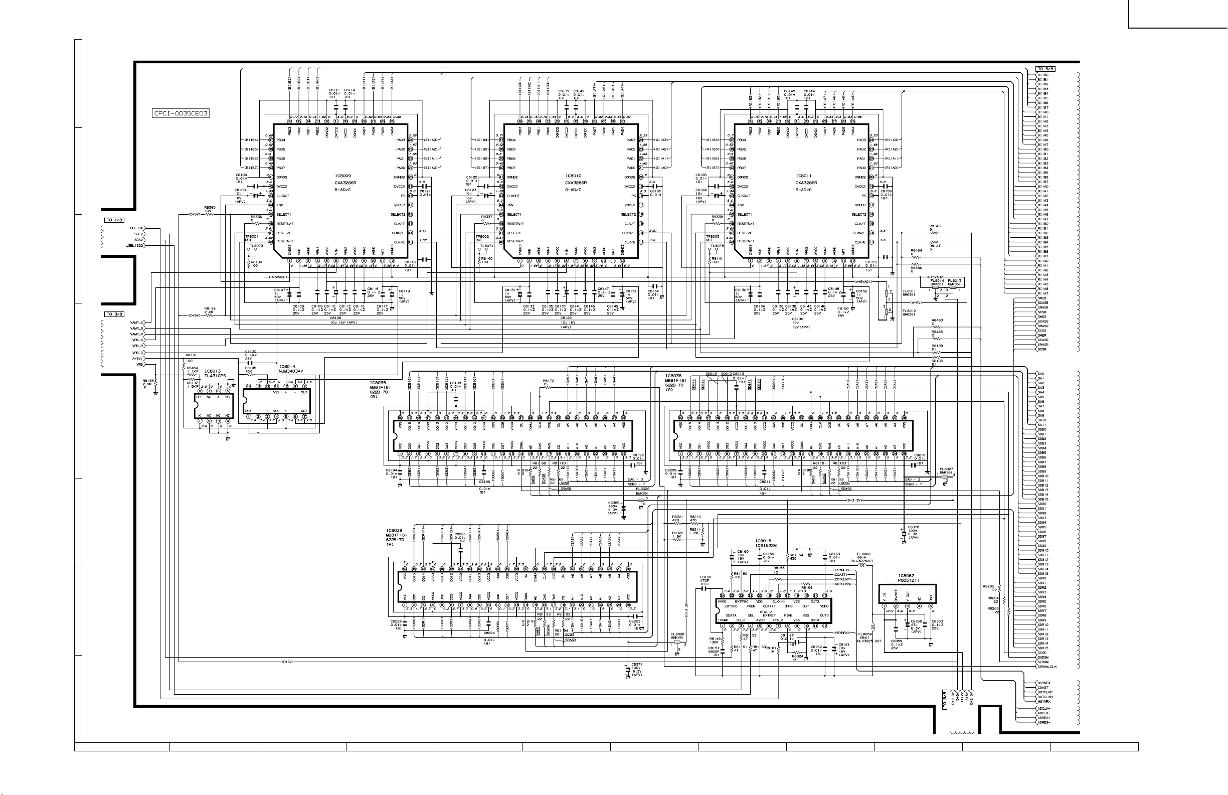
XV-DW100U
Ë
PC I/F UNIT-4/8
H
G
F
E
D
C
B
A
121110987654321
98
99
Page 77

XV-DW100U
Ë
PC I/F UNIT-5/8
H
G
F
E
D
C
B
A
121110987654321
100
101
Page 78

XV-DW100U
Ë
PC I/F UNIT-6/8
H
G
F
E
D
C
B
A
121110987654321
102
103
Page 79

XV-DW100U
Ë
PC I/F UNIT-7/8
H
G
F
E
D
C
B
A
121110987654321
104
105
Page 80

XV-DW100U
Ë
PC I/F UNIT-8/8
H
G
F
E
D
C
B
A
121110987654321
106
107
Page 81

XV-DW100U
PRINTED WIRING BOARD ASSEMBLIES
H
G
F
E
Signal Unit (Wiring Side)
D
C
B
A
Signal Unit (Component Side)
654321
108
Page 82

XV-DW100U
H
G
F
E
T erminal Unit (Wiring Side)
D
C
B
A
Terminal Unit (Component Side)
654321
109
Page 83

XV-DW100U
H
G
F
E
D
C
R/C Receiver Unit
(Wiring Side)
B
A
Output Unit (Wiring Side)
654321
110
Page 84

XV-DW100U
H
G
F
E
D
C
R/C Receiver Unit
(Component Side)
B
A
Output Unit (Component Side)
654321
111
Page 85

XV-DW100U
H
G
F
E
D
C
B
A
PC I/F Unit (Wiring Side)
654321
112
Page 86

XV-DW100U
H
G
F
E
D
C
B
A
PC I/F Unit (Component Side)
654321
113
Page 87

XV-DW100U
H
G
F
Filter Unit (Wiring Side)
E
D
C
B
Sound Out Unit (Wiring Side)
A
Power Unit (Wiring Side)
654321
114
Page 88

XV-DW100U
H
G
Filter Unit (Component Side)
F
E
D
C
B
Sound Out Unit (Component Side)
A
Power Unit (Component Side)
654321
115
Page 89

XV-DW100U
H
G
F
E
D
C
B
Inlet Unit (Wiring Side)
Inlet Unit (Component Side)
A
654321
116
Page 90

XV-DW100U
Ref. No. Part No. ★ Description Code Ref. No. Part No. ★ Description Code
PARTS LIST
PARTS REPLACEMENT
Parts marked with "å" are important for maintaining the safety of
the set. Be sure to replace these parts with specified ones for maintaining the safety and performance of the set.
Les pieces marquées "å" sont importantes pour maintenir la sécurité
de l'appareil. Ne remplacer ces pieces que par des pieces dont le
numéro est spécifié pour maintenir la sécurité et protéger le bon
fonctinnement de l'appareil.
"HOW TO ORDER REPLACEMENT PARTS"
To have your order filled promptly and correctly, please furnish the
following informations.
1. MODEL NUMBER 2. REF. NO.
3. PART NO. 4. DESCRIPTION
5. CODE 6. QUANTITY
in USA: Contact your nearest SHARP Parts Distributor.
For location of SHARP Parts Distributor,
Please call Toll-Free; 1-800-BE-SHARP
in CANADA: Contact SHARP Electronics of Canada Limited
Phone (416) 890-2100.
★ MARK: SPARE PARTS-DELIVERY SECTION
Ref. No. Part No. ★ Description Code
LCD PANELS
NOTE: THE PARTS HERES SHOWN ARE SUPPLIED
AS AN ASSEMBLY BUT NOT INDEPENEDENTLY.
RLCDP0102CEZZ J LCD Module Unit, Red DK
RLCDP0103CEZZ J LCD Module Unit, Green DK
RLCDP0104CEZZ J LCD Module Unit, Blue DK
PRINTED WIRING BOARD ASSEMBLIES
(NOT REPLACEMENT ITEM)
DUNTK9921DE05 – Signal Unit —
DUNTKA111DE01 – Output Unit —
DUNTK9923DE05 – Terminal Unit —
DUNTKA112DE01 – Sound Out Unit —
DUNTKA113DE01 – R/C Receiver Unit —
RUNTK0656CEZZ – Inlet Unit —
RDENC0287CEZZ – Power Unit —
RDENC0288CEZZ – Filter Unit —
CPCi-0035CE03 – PC I/F Unit —
RDENC0286CEZZ J Ballast Unit CE
(Unit Replacement Item)
DUNTK9921DE05
SIGNAL UNIT
INTEGRATED CIRCUITS
IC801 VHiTDA8854H-2 J TDA8854H/N2 BD
IC802 VHiTHC4538T-1 J TC74HC4538AFT AL
IC803 VHiTHC4538T-1 J TC74HC4538AFT AL
IC805 VHiTDA4565/-1 J TDA4565/V6 AN
IC807 VHiNJM2060V-1 J NJM2060V AF
IC4301 VHiCXA1839Q-1 J CXA1839 AZ
IC4302 VHiTHC4538T-1 J TC74HC4538AFT AL
IC4501 VHiPD64081B-1 J UPD64081BGF3BA BD
IC4502 VHiMC14577F-1 J MC14577BF AG
IC4503 RH-iX3084CEZZ J HY514264BJC-50 AS
IC4505 VHiPST600iM-1 J IC-PST600IMT AE
IC4506 VHiT7SET08U-1 J TC7SET08FU AE
IC4507 VHiM40C568H-1 J MB40C568HPFV-G AQ
IC4508 VHiTC4S66F/-1 J TC4S66F AD
IC4509 VHiNJM2233V-1 J NJM2233V AE
IC6001 VHiTC90A11F-1 J TC90A11F AZ
IC6002 VHiM518221S-1 J MSM518221-30JS BA
IC6003 VHiPST600DM-1 J IC-PST600DMT AE
IC6004 VHiNJM2283V-1 J NJM2283V AG
IC6008 VHiBA7046F/-1 J BA7046F AF
IC6009 VHiNJM2283V-1 J NJM2283V AG
IC6010 VHiNJM2234M-1 J NJM2234M AF
IC6011 VHiNJM2240M-1 J NJM2240M AG
TRANSISTORS
Q801 VS2PD601AR/-1 J 2PD601AR AB
Q802 VS2PB709AR/-1 J 2PB709AR AB
Q803 VS2PD601AR/-1 J 2PD601AR AB
Q804 VS2PB709AR/-1 J 2PB709AR AB
Q805 VSDTC144EK/-1 J DTC144EK AB
Q806 VS2PD601AR/-1 J 2PD601AR AB
Q807 VS2PD601AR/-1 J 2PD601AR AB
Q808 VS2PD601AR/-1 J 2PD601AR AB
Q811 VSDTC144EK/-1 J DTC144EK AB
Q812 VS2PD601AR/-1 J 2PD601AR AB
Q813 VS2PD601AR/-1 J 2PD601AR AB
Q814 VS2PD601AR/-1 J 2PD601AR AB
Q4303 VS2PD601AR/-1 J 2PD601AR AB
Q4306 VS2PD601AR/-1 J 2PD601AR AB
Q4309 VS2PD601AR/-1 J 2PD601AR AB
Q4313 VS2PD601AR/-1 J 2PD601AR AB
Q4314 VS2PD601AR/-1 J 2PD601AR AB
Q4315 VS2PD601AR/-1 J 2PD601AR AB
Q4317 VS2PD601AR/-1 J 2PD601AR AB
Q4318 VS2PD601AR/-1 J 2PD601AR AB
Q4320 VSDTC144EU/-1 J DTC144EU AB
Q4321 VSBSN20////-1 J BSN20 AD
Q4322 VSBSN20////-1 J BSN20 AD
Q4501 VS2PB709AR/-1 J 2PB709AR AB
Q4502 VS2PB709AR/-1 J 2PB709AR AB
Q4503 VS2PB709AR/-1 J 2PB709AR AB
Q4504 VS2PB709AR/-1 J 2PB709AR AB
Q4505 VS2SC2412KQ-1 J 2SC2412KQ AA
Q4506 VS2PD601AR/-1 J 2PD601AR AB
Q4507 VS2PB709AR/-1 J 2PB709AR AB
Q4508 VS2PD601AR/-1 J 2PD601AR AB
Q4509 VS2PB709AR/-1 J 2PB709AR AB
Q4510 VS2PB709AR/-1 J 2PB709AR AB
Q4511 VS2PD601AR/-1 J 2PD601AR AB
Q4520 VS2PB709AR/-1 J 2PB709AR AB
Q6001 VS2PD601AR/-1 J 2PD601AR AB
Q6002 VS2PD601AR/-1 J 2PD601AR AB
Q6003 VS2PB709AR/-1 J 2PB709AR AB
Q6004 VS2PD601AR/-1 J 2PD601AR AB
Q6005 VS2PB709AR/-1 J 2PB709AR AB
Q6006 VS2PD601AR/-1 J 2PD601AR AB
Q6007 VS2PD601AR/-1 J 2PD601AR AB
Q6008 VS2PD601AR/-1 J 2PD601AR AB
Q6009 VS2PD601AR/-1 J 2PD601AR AB
Q6010 VS2PD601AR/-1 J 2PD601AR AB
117
Page 91

XV-DW100U
Ref. No. Part No. ★ Description Code Ref. No. Part No. ★ Description Code
DUNTK9921DE05
SIGNAL UNIT (Continued)
Q6011 VS2PD601AR/-1 J 2PD601AR AB
Q6012 VS2PD601AR/-1 J 2PD601AR AB
Q6013 VS2PD601AR/-1 J 2PD601AR AB
DIODES
D801 VHDDAN202K/-1 J Diode AB
D804 VHDMA152WA/-1 J Diode AA
D6001 RH-EX0226CEZZ J Zener Diode AB
D6002 RH-EX0226CEZZ J Zener Diode AB
PACKAGED CIRCUITS
X801 RCRSB0009PEZZ J Crystal AL
X802 RCRSB0008PEZZ J Crystal AH
X4501 RCRSB0258CEZZ J Crystal AG
FILTERS AND COILS
FL4501 RCiLF0306CEZZ J Filter AH
FL4502 RCiLV0108GEZZ J Filter AG
FL4503 RFiLN0097GEZZ J Filter AF
FL4504 RFiLN0097GEZZ J Filter AF
L801 VP-1M330J4R2N J Peaking 33µH AC
L4501 VP-1M4R7J1R2N J Peaking 4.7µH AB
L4502 VP-1M220J2R9N J Peaking 22µH AC
L4510 VP-1M220J2R9N J Peaking 22µH AC
L6001 VP-1M270J3R8N J Peaking 27µH AC
L6002 VP-1M330J4R2N J Peaking 33µH AC
L6003 VP-1M220J2R9N J Peaking 22µH AC
CAPACITORS
C801 VCKYCY1EF104Z J 0.1 25V Ceramic AA
C802 VCKYCY1EF104Z J 0.1 25V Ceramic AA
C803 VCEAPF1HW225M J 2.2 50V Electrolytic AB
C804 VCFYEC1CM223J J 0.022 16V Mylar AC
C805 VCKYCY1HB103K J 0.01 50V Ceramic AA
C806 VCFYEC1CM274J J 0.27 16V Mylar AE
C807 VCKYCY1EF104Z J 0.1 25V Ceramic AA
C808 VCEAPF1CW107M J 100 16V Electrolytic AD
C809 VCKYCY1EF104Z J 0.1 25V Ceramic AA
C810 VCFYEC1CM274J J 0.27 16V Mylar AE
C811 VCKYCY1CF224Z J 0.22 16V Ceramic AA
C812 VCEAPF1CW106M J 10 16V Electrolytic AB
C813 VCKYCY1EF104Z J 0.1 25V Ceramic AA
C814 VCKYCY1EF104Z J 0.1 25V Ceramic AA
C815 VCKYCY1EF104Z J 0.1 25V Ceramic AA
C816 VCE9PF1CW106M J 10 16V Elect. (N.P) AC
C817 VCKYCY1EF104Z J 0.1 25V Ceramic AA
C818 VCKYCY1EF104Z J 0.1 25V Ceramic AA
C819 VCKYCY1EF104Z J 0.1 25V Ceramic AA
C820 VCKYCY1EF104Z J 0.1 25V Ceramic AA
C821 VCKYCY1EF104Z J 0.1 25V Ceramic AA
C823 VCCCCY1HH180J J 18p 50V Ceramic AA
C824 VCCCCY1HH180J J 18p 50V Ceramic AA
C825 VCFRED1HM332J J 3300p 50V Mylar AD
C826 VCKYCY1EF104Z J 0.1 25V Ceramic AA
C827 VCEAPF1CW107M J 100 16V Electrolytic AD
C828 VCKYCY1EF104Z J 0.1 25V Ceramic AA
C829 VCKYCY1EF104Z J 0.1 25V Ceramic AA
C830 VCFRED1HM222J J 2200p 50V Mylar AC
C831 VCEAPF1HW105M J 1 50V Electrolytic AB
C832 VCFRED1HM472J J 4700p 50V Mylar AD
C834 VCE9PF1CW106M J 10 16V Elect. (N.P) AC
C835 VCEAPF1CW106M J 10 16V Electrolytic AB
C836 VCEAPF1CW106M J 10 16V Electrolytic AB
C837 VCKYCY1HB103K J 0.01 50V Ceramic AA
C841 VCKYCY1EF104Z J 0.1 25V Ceramic AA
C842 VCKYCY1EF104Z J 0.1 25V Ceramic AA
C843 VCCCCY1EH102J J 1000p 25V Ceramic AB
C844 VCCCCY1EH102J J 1000p 25V Ceramic AB
C845 VCKYCY1EF104Z J 0.1 25V Ceramic AA
C846 VCCCCY1EH102J J 1000p 25V Ceramic AB
C847 VCCCCY1EH102J J 1000p 25V Ceramic AB
C855 VCKYCY1EF104Z J 0.1 25V Ceramic AA
C856 VCKYCY1EF104Z J 0.1 25V Ceramic AA
C858 VCE9PF1HW105M J 1 50V Elect. (N.P) AC
C859 VCE9PF1HW105M J 1 50V Elect. (N.P) AC
C860 VCCCCY1HH820J J 82p 50V Ceramic AA
C862 VCEAPF1CW226M J 22 16V Electrolytic AB
C863 VCKYCY1CF104Z J 0.1 16V Ceramic AA
C864 VCCCCY1HH221J J 220p 50V Ceramic AA
C865 VCCCCY1HH221J J 220p 50V Ceramic AA
C866 VCCCCY1HH680J J 68p 50V Ceramic AA
C867 VCCCCY1HH121J J 120p 50V Ceramic AA
C868 VCCCCY1HH121J J 120p 50V Ceramic AA
C870 VCEAPF1CW476M J 47 16V Electrolytic AC
C875 VCKYCY1EF104Z J 0.1 25V Ceramic AA
C877 VCKYCY1EF104Z J 0.1 25V Ceramic AA
C878 VCEAPF1HW225M J 2.2 50V Electrolytic AB
C879 VCE9PF1HW105M J 1 50V Elect. (N.P) AC
C880 VCCCCY1HH101J J 100p 50V Ceramic AA
C883 VCKYCY1CF104Z J 0.1 16V Ceramic AA
C890 VCEAPF1EW475M J 4.7 25V Electrolytic AB
C891 VCEAPF1EW475M J 4.7 25V Electrolytic AB
C922 VCKYCY1HB103K J 0.01 50V Ceramic AA
C937 VCKYCY1EF104Z J 0.1 25V Ceramic AA
C938 VCCCCY1HH390J J 39p 50V Ceramic AA
C939 VCKYCY1EF104Z J 0.1 25V Ceramic AA
C940 VCKYCY1EF104Z J 0.1 25V Ceramic AA
C976 VCKYCY1HB103K J 0.01 50V Ceramic AA
C4301 VCEAPF1CW106M J 10 16V Electrolytic AB
C4302 VCEAPF1CW106M J 10 16V Electrolytic AB
C4303 VCEAPF1HW106M J 10 50V Electrolytic AB
C4305 VCKYCY1CF104Z J 0.1 16V Ceramic AA
C4306 VCKYCY1HB103K J 0.01 50V Ceramic AA
C4307 VCKYCY1HB103K J 0.01 50V Ceramic AA
C4308 VCKYCY1HB103K J 0.01 50V Ceramic AA
C4309 VCKYCY1HB103K J 0.01 50V Ceramic AA
C4310 VCKYCY1HB103K J 0.01 50V Ceramic AA
C4311 VCKYCY1HB103K J 0.01 50V Ceramic AA
C4312 VCKYCY1CF104Z J 0.1 16V Ceramic AA
C4313 VCKYCY1HB103K J 0.01 50V Ceramic AA
C4314 VCKYCY1HB103K J 0.01 50V Ceramic AA
C4315 VCKYCY1HB103K J 0.01 50V Ceramic AA
C4316 VCEAPF1CW106M J 10 16V Electrolytic AB
C4317 VCEAPF1HW474M J 0.47 50V Electrolytic AB
C4318 VCEAPF1CW476M J 47 16V Electrolytic AC
C4319 VCKYCY1CF104Z J 0.1 16V Ceramic AA
C4320 VCKYCY1CF104Z J 0.1 16V Ceramic AA
C4321 VCKYCY1CF104Z J 0.1 16V Ceramic AA
C4322 VCCCCY1HH561J J 560p 50V Ceramic AB
C4323 VCCCCY1EH821J J 820p 25V Ceramic AB
C4327 VCEAPF1HW225M J 2.2 50V Electrolytic AB
C4328 VCEAPF1CW106M J 10 16V Electrolytic AB
C4501 VCKYCY1HB103K J 0.01 50V Ceramic AA
C4502 VCCCCY1HH270J J 27p 50V Ceramic AA
C4503 VCEAPF1CW476M J 47 16V Electrolytic AC
C4504 VCKYCY1CF104Z J 0.1 16V Ceramic AA
C4505 VCKYCY1CF104Z J 0.1 16V Ceramic AA
C4507 VCCCCY1HH120J J 12p 50V Ceramic AA
C4508 VCCCCY1HH270J J 27p 50V Ceramic AA
C4509 VCCCCY1HH100D J 10p 50V Ceramic AA
C4510 VCKYCY1CF104Z J 0.1 16V Ceramic AA
C4511 VCKYCY1CF104Z J 0.1 16V Ceramic AA
C4512 VCKYCY1CF104Z J 0.1 16V Ceramic AA
C4513 VCEAPF1CW106M J 10 16V Electrolytic AB
C4515 VCKYCY1EF104Z J 0.1 25V Ceramic AA
C4516 VCKYCY1CF104Z J 0.1 16V Ceramic AA
C4517 VCKYCY1CF104Z J 0.1 16V Ceramic AA
C4518 VCKYCY1CF104Z J 0.1 16V Ceramic AA
C4519 VCKYCY1CF104Z J 0.1 16V Ceramic AA
C4520 VCKYCY1CF104Z J 0.1 16V Ceramic AA
C4521 VCKYCY1CF104Z J 0.1 16V Ceramic AA
C4522 VCKYCY1CF104Z J 0.1 16V Ceramic AA
C4523 VCEAPF0JW107M J 100 6.3V Electrolytic AC
C4524 VCEAPF0JW107M J 100 6.3V Electrolytic AC
C4525 VCEAPF0JW476M J 47 6.3V Electrolytic AB
C4526 VCKYCY1CF104Z J 0.1 16V Ceramic AA
118
Page 92

XV-DW100U
Ref. No. Part No. ★ Description Code Ref. No. Part No. ★ Description Code
DUNTK9921DE05
SIGNAL UNIT (Continued)
C4527 VCKYCY1CF104Z J 0.1 16V Ceramic AA
C4528 VCEAPF0JW476M J 47 6.3V Electrolytic AB
C4529 VCKYCY1HB103K J 0.01 50V Ceramic AA
C4530 VCKYCY1HB103K J 0.01 50V Ceramic AA
C4531 VCKYCY1EF104Z J 0.1 25V Ceramic AA
C4533 VCKYCY1CF104Z J 0.1 16V Ceramic AA
C4534 VCKYCY1CF104Z J 0.1 16V Ceramic AA
C4535 VCCCCY1HH220J J 22p 50V Ceramic AA
C4536 VCCCCY1HH220J J 22p 50V Ceramic AA
C4537 VCKYCY1CF104Z J 0.1 16V Ceramic AA
C4538 VCKYCY1CF104Z J 0.1 16V Ceramic AA
C4539 VCKYCY1CF104Z J 0.1 16V Ceramic AA
C4540 VCCCCY1HH391J J 390p 50V Ceramic AA
C4541 VCKYCY1CF104Z J 0.1 16V Ceramic AA
C4542 VCEAPF1CW106M J 10 16V Electrolytic AB
C4543 VCKYCY1CF104Z J 0.1 16V Ceramic AA
C4545 VCKYCY1CF104Z J 0.1 16V Ceramic AA
C4546 VCEAPF1HW474M J 0.47 50V Electrolytic AB
C4548 VCKYCY1CF104Z J 0.1 16V Ceramic AA
C4549 VCCCCY1HH471J J 470p 50V Ceramic AA
C4550 VCEAPF1HW334M J 0.33 50V Electrolytic AB
C4551 VCKYCY1CF104Z J 0.1 16V Ceramic AA
C4552 VCE9PF1HW105M J 1 50V Elect. (N.P) AC
C4553 VCKYCY1CF104Z J 0.1 16V Ceramic AA
C4554 VCCCCY1HH101J J 100p 50V Ceramic AA
C4555 VCKYCY1CF104Z J 0.1 16V Ceramic AA
C4556 RC-KZ0416CEZZ J 10 25V Ceramic AE
C4557 VCKYCY1CF104Z J 0.1 16V Ceramic AA
C4558 VCKYCY1CF104Z J 0.1 16V Ceramic AA
C4559 RC-KZ0416CEZZ J 10 25V Ceramic AE
C4560 VCKYCY1CF104Z J 0.1 16V Ceramic AA
C4561 VCKYCY1CF104Z J 0.1 16V Ceramic AA
C4562 VCEAPF1CW226M J 22 16V Electrolytic AB
C4563 VCEAPF1CW226M J 22 16V Electrolytic AB
C4564 VCKYCY1CF104Z J 0.1 16V Ceramic AA
C4590 VCCCCY1HH100D J 10p 50V Ceramic AA
C4591 VCCCCY1HH270J J 27p 50V Ceramic AA
C4592 VCCCCY1HH120J J 12p 50V Ceramic AA
C4594 RC-EZ0822CEZZ J 10 6.3V Electrolytic AD
C4595 RC-EZ0822CEZZ J 10 6.3V Electrolytic AD
C6001 VCKYCY1CF104Z J 0.1 16V Ceramic AA
C6002 VCKYCY1CF104Z J 0.1 16V Ceramic AA
C6003 VCKYCY1CF104Z J 0.1 16V Ceramic AA
C6004 VCKYCY1HB103K J 0.01 50V Ceramic AA
C6005 VCKYCY1CF104Z J 0.1 16V Ceramic AA
C6006 VCEAPF0JW476M J 47 6.3V Electrolytic AB
C6007 VCKYCY1HB103K J 0.01 50V Ceramic AA
C6008 VCCCCY1HH181J J 180p 50V Ceramic AA
C6009 VCKYCY1CF104Z J 0.1 16V Ceramic AA
C6010 VCKYCY1CF104Z J 0.1 16V Ceramic AA
C6011 VCKYCY1CF104Z J 0.1 16V Ceramic AA
C6012 VCKYCY1CF104Z J 0.1 16V Ceramic AA
C6013 VCKYCY1CF104Z J 0.1 16V Ceramic AA
C6014 VCKYCY1CF104Z J 0.1 16V Ceramic AA
C6015 VCKYCY1CF104Z J 0.1 16V Ceramic AA
C6016 VCKYCY1CF104Z J 0.1 16V Ceramic AA
C6017 VCKYCY1CF104Z J 0.1 16V Ceramic AA
C6018 VCKYCY1CF104Z J 0.1 16V Ceramic AA
C6019 VCKYCY1CF104Z J 0.1 16V Ceramic AA
C6020 VCEAPF0JW476M J 47 6.3V Electrolytic AB
C6021 VCKYCY1CF104Z J 0.1 16V Ceramic AA
C6022 VCKYCY1CF104Z J 0.1 16V Ceramic AA
C6023 VCKYCY1CF104Z J 0.1 16V Ceramic AA
C6024 VCKYCY1CF104Z J 0.1 16V Ceramic AA
C6025 VCKYCY1CF104Z J 0.1 16V Ceramic AA
C6026 VCKYCY1AF105Z J 1 10V Ceramic AC
C6028 VCCCCY1HH470J J 47p 50V Ceramic AA
C6029 VCCCCY1HH330J J 33p 50V Ceramic AA
C6030 VCKYCY1HB103K J 0.01 50V Ceramic AA
C6031 VCKYCY1CF104Z J 0.1 16V Ceramic AA
C6032 VCKYCY1HB103K J 0.01 50V Ceramic AA
C6033 VCKYCY1CF104Z J 0.1 16V Ceramic AA
C6034 VCE9PF1HW105M J 1 50V Elect. (N.P) AC
C6035 VCEAPF0JW476M J 47 6.3V Electrolytic AB
C6037 VCCCCY1HH360J J 36p 50V Ceramic AA
C6038 VCCCCY1HH120J J 12p 50V Ceramic AA
C6039 VCEAPF1CW106M J 10 16V Electrolytic AB
C6040 VCKYCY1CF104Z J 0.1 16V Ceramic AA
C6041 VCEAPF1CW106M J 10 16V Electrolytic AB
C6042 VCCCCY1HH5R0C J 5p 50V Ceramic AA
C6043 VCCCCY1HH220J J 22p 50V Ceramic AA
C6044 VCCCCY1HH220J J 22p 50V Ceramic AA
C6045 VCKYCY1CF104Z J 0.1 16V Ceramic AA
C6046 VCCCCY1HH391J J 390p 50V Ceramic AA
C6047 VCKYCY1CF104Z J 0.1 16V Ceramic AA
C6048 VCKYCY1CF104Z J 0.1 16V Ceramic AA
C6049 VCEAPF1CW226M J 22 16V Electrolytic AB
C6050 VCKYCY1CF104Z J 0.1 16V Ceramic AA
C6051 VCEAPF1CW226M J 22 16V Electrolytic AB
C6052 VCKYCY1CF104Z J 0.1 16V Ceramic AA
C6064 VCEAPF0JW476M J 47 6.3V Electrolytic AB
C6065 VCKYCY1HB103K J 0.01 50V Ceramic AA
C6066 VCKYCY1AF105Z J 1 10V Ceramic AC
C6067 VCCCCY1EH102J J 1000p 25V Ceramic AB
C6068 VCKYCY1CF104Z J 0.1 16V Ceramic AA
C6069 VCKYCY1CF104Z J 0.1 16V Ceramic AA
C6070 VCKYCY1HB103K J 0.01 50V Ceramic AA
C6071 VCEAPF1CW226M J 22 16V Electrolytic AB
C6072 VCKYCY1HB103K J 0.01 50V Ceramic AA
C6074 VCEAPF1CW476M J 47 16V Electrolytic AC
C6075 VCEAPF1CW226M J 22 16V Electrolytic AB
C6076 VCEAPF1CW226M J 22 16V Electrolytic AB
C6077 VCEAPF1CW226M J 22 16V Electrolytic AB
C6078 VCKYCY1CF104Z J 0.1 16V Ceramic AA
C6079 VCKYCY1CF104Z J 0.1 16V Ceramic AA
C6080 VCKYCY1CF104Z J 0.1 16V Ceramic AA
C6081 VCKYCY1CF104Z J 0.1 16V Ceramic AA
C6082 VCKYCY1CF104Z J 0.1 16V Ceramic AA
C6083 VCKYCY1CF104Z J 0.1 16V Ceramic AA
C6084 VCKYCY1CF104Z J 0.1 16V Ceramic AA
C6085 VCEAPF1CW106M J 10 16V Electrolytic AB
C6086 VCKYCY1HF103Z J 0.01 50V Ceramic AA
C6087 VCCCCY1HH5R0C J 5p 50V Ceramic AA
C6088 VCEAPF1HW475M J 4.7 50V Electrolytic AB
C6089 VCKYCY1HF103Z J 0.01 50V Ceramic AA
C6090 VCKYCY1HF102Z J 1000p 50V Ceramic AA
C6091 VCKYCY1HB103K J 0.01 50V Ceramic AA
C6093 VCEAPF1CW226M J 22 16V Electrolytic AB
C6094 VCE9PF1CW226M J 22 16V Elect. (N.P) AD
RESISTORS
R801 VRS-CY1JF333J J 33k 1/16W Metal Oxide AA
R802 VRS-CY1JF102J J 1k 1/16W Metal Oxide AA
R803 VRS-CY1JF564J J 560k 1/16W Metal Oxide AA
R804 VRS-CY1JF393J J 39k 1/16W Metal Oxide AA
R806 VRS-CY1JF102J J 1k 1/16W Metal Oxide AA
R807 VRS-CY1JF821J J 820 1/16W Metal Oxide AA
R808 VRS-CY1JF221J J 220 1/16W Metal Oxide AA
R809 VRS-CY1JF102J J 1k 1/16W Metal Oxide AA
R810 VRS-CY1JF101J J 100 1/16W Metal Oxide AA
R811 VRS-CY1JF101J J 100 1/16W Metal Oxide AA
R812 VRS-CY1JF000J J 0 1/16W Metal Oxide AA
R813 VRS-TX2HF4R7J J 4.7 1/2W Metal Oxide AB
R815 VRS-CY1JF330J J 33 1/16W Metal Oxide AA
R816 VRS-CY1JF330J J 33 1/16W Metal Oxide AA
R817 VRS-CY1JF330J J 33 1/16W Metal Oxide AA
R818 VRS-CY1JF473J J 47k 1/16W Metal Oxide AA
R819 VRS-CY1JF103J J 10k 1/16W Metal Oxide AA
R820 VRS-CY1JF682J J 6.8k 1/16W Metal Oxide AA
R821 VRS-CY1JF392J J 3.9k 1/16W Metal Oxide AA
R822 VRS-CY1JF101J J 100 1/16W Metal Oxide AA
R823 VRS-CY1JF332J J 3.3k 1/16W Metal Oxide AA
R824 VRS-CY1JF682J J 6.8k 1/16W Metal Oxide AA
R825 VRS-CY1JF392J J 3.9k 1/16W Metal Oxide AA
R826 VRS-CY1JF102J J 1k 1/16W Metal Oxide AA
R827 VRS-CY1JF102J J 1k 1/16W Metal Oxide AA
119
Page 93

XV-DW100U
Ref. No. Part No. ★ Description Code Ref. No. Part No. ★ Description Code
DUNTK9921DE05
SIGNAL UNIT (Continued)
R829 VRS-CY1JF101J J 100 1/16W Metal Oxide AA
R830 VRS-CY1JF104J J 100k 1/16W Metal Oxide AA
R831 VRS-TX2HF4R7J J 4.7 1/2W Metal Oxide AB
R832 VRS-CY1JF000J J 0 1/16W Metal Oxide AA
R833 VRS-CY1JF152J J 1.5k 1/16W Metal Oxide AA
R834 VRS-CY1JF562J J 5.6k 1/16W Metal Oxide AA
R835 VRS-CY1JF103J J 10k 1/16W Metal Oxide AA
R836 VRS-CY1JF000J J 0 1/16W Metal Oxide AA
R837 VRS-CY1JF472J J 4.7k 1/16W Metal Oxide AA
R838 VRS-CY1JF103J J 10k 1/16W Metal Oxide AA
R839 VRS-CY1JF472J J 4.7k 1/16W Metal Oxide AA
R840 VRS-CY1JF103J J 10k 1/16W Metal Oxide AA
R841 VRS-CY1JF104J J 100k 1/16W Metal Oxide AA
R842 VRS-CY1JF000J J 0 1/16W Metal Oxide AA
R843 VRS-CY1JF223J J 22k 1/16W Metal Oxide AA
R844 VRS-CY1JF152J J 1.5k 1/16W Metal Oxide AA
R845 VRS-CY1JF223J J 22k 1/16W Metal Oxide AA
R846 VRS-CY1JF681J J 680 1/16W Metal Oxide AA
R847 VRS-CY1JF102J J 1k 1/16W Metal Oxide AA
R848 VRS-CY1JF271J J 270 1/16W Metal Oxide AA
R849 VRS-TX2HF5R6J J 5.6 1/2W Metal Oxide AA
R850 VRS-CY1JF273J J 27k 1/16W Metal Oxide AA
R851 VRS-CY1JF273J J 27k 1/16W Metal Oxide AA
R852 VRS-CY1JF103J J 10k 1/16W Metal Oxide AA
R853 VRS-CY1JF331J J 330 1/16W Metal Oxide AA
R854 VRS-CY1JF750J J 75 1/16W Metal Oxide AA
R855 VRS-CY1JF471J J 470 1/16W Metal Oxide AA
R856 VRS-CY1JF822J J 8.2k 1/16W Metal Oxide AA
R857 VRS-CY1JF471J J 470 1/16W Metal Oxide AA
R858 VRS-CY1JF562J J 5.6k 1/16W Metal Oxide AA
R859 VRS-CY1JF102J J 1k 1/16W Metal Oxide AA
R860 VRN-CY1JF133D J 13k 1/16W Metal Film AB
R861 VRN-CY1JF752D J 7.5k 1/16W Metal Film AA
R862 VRN-CY1JF682D J 6.8k 1/16W Metal Film AB
R863 VRN-CY1JF103D J 10k 1/16W Metal Film AA
R864 VRS-CY1JF182J J 1.8k 1/16W Metal Oxide AA
R865 VRS-CY1JF101J J 100 1/16W Metal Oxide AA
R872 VRS-CY1JF332J J 3.3k 1/16W Metal Oxide AA
R874 VRS-TX2HF5R6J J 5.6 1/2W Metal Oxide AA
R876 VRS-CY1JF331J J 330 1/16W Metal Oxide AA
R879 VRS-CY1JF681J J 680 1/16W Metal Oxide AA
R880 VRS-CY1JF183J J 18k 1/16W Metal Oxide AA
R881 VRS-CY1JF000J J 0 1/16W Metal Oxide AA
R882 VRS-CY1JF101J J 100 1/16W Metal Oxide AA
R883 VRS-CY1JF101J J 100 1/16W Metal Oxide AA
R886 VRS-CY1JF000J J 0 1/16W Metal Oxide AA
R891 VRS-CY1JF000J J 0 1/16W Metal Oxide AA
R899 VRS-CY1JF103J J 10k 1/16W Metal Oxide AA
R900 VRS-CY1JF682J J 6.8k 1/16W Metal Oxide AA
R901 VRS-CY1JF223J J 22k 1/16W Metal Oxide AA
R902 VRS-CY1JF273J J 27k 1/16W Metal Oxide AA
R903 VRS-CY1JF472J J 4.7k 1/16W Metal Oxide AA
R905 VRS-CY1JF223J J 22k 1/16W Metal Oxide AA
R906 VRS-CY1JF223J J 22k 1/16W Metal Oxide AA
R907 VRS-CY1JF103J J 10k 1/16W Metal Oxide AA
R908 VRS-CY1JF103J J 10k 1/16W Metal Oxide AA
R909 VRS-CY1JF224J J 220k 1/16W Metal Oxide AA
R910 VRS-CY1JF222J J 2.2k 1/16W Metal Oxide AA
R911 VRS-CY1JF683J J 68k 1/16W Metal Oxide AA
R912 VRS-CY1JF102J J 1k 1/16W Metal Oxide AA
R913 VRS-CY1JF103J J 10k 1/16W Metal Oxide AA
R914 VRS-CY1JF103J J 10k 1/16W Metal Oxide AA
R920 VRS-CY1JF102J J 1k 1/16W Metal Oxide AA
R921 VRS-CY1JF102J J 1k 1/16W Metal Oxide AA
R922 VRS-CY1JF102J J 1k 1/16W Metal Oxide AA
R925 VRS-CY1JF000J J 0 1/16W Metal Oxide AA
R926 VRS-CY1JF000J J 0 1/16W Metal Oxide AA
R929 VRS-CY1JF102J J 1k 1/16W Metal Oxide AA
R930 VRS-CY1JF102J J 1k 1/16W Metal Oxide AA
R935 VRS-CY1JF333J J 33k 1/16W Metal Oxide AA
R936 VRS-CY1JF363J J 36k 1/16W Metal Oxide AA
R4307 VRS-CY1JF273J J 27k 1/16W Metal Oxide AA
R4308 VRS-CY1JF153J J 15k 1/16W Metal Oxide AA
R4309 VRS-CY1JF000J J 0 1/16W Metal Oxide AA
R4310 VRS-CY1JF392J J 3.9k 1/16W Metal Oxide AA
R4315 VRS-CY1JF153J J 15k 1/16W Metal Oxide AA
R4316 VRS-CY1JF273J J 27k 1/16W Metal Oxide AA
R4317 VRS-CY1JF000J J 0 1/16W Metal Oxide AA
R4318 VRS-CY1JF392J J 3.9k 1/16W Metal Oxide AA
R4322 VRS-CY1JF273J J 27k 1/16W Metal Oxide AA
R4323 VRS-CY1JF273J J 27k 1/16W Metal Oxide AA
R4324 VRS-CY1JF000J J 0 1/16W Metal Oxide AA
R4331 VRS-CY1JF273J J 27k 1/16W Metal Oxide AA
R4332 VRS-CY1JF101J J 100 1/16W Metal Oxide AA
R4333 VRS-CY1JF101J J 100 1/16W Metal Oxide AA
R4334 VRS-CY1JF101J J 100 1/16W Metal Oxide AA
R4335 VRS-CY1JF102J J 1k 1/16W Metal Oxide AA
R4336 VRS-CY1JF102J J 1k 1/16W Metal Oxide AA
R4337 VRS-CY1JF102J J 1k 1/16W Metal Oxide AA
R4338 VRS-CY1JF103J J 10k 1/16W Metal Oxide AA
R4339 VRS-CY1JF000J J 0 1/16W Metal Oxide AA
R4340 VRS-CY1JF000J J 0 1/16W Metal Oxide AA
R4341 VRS-CY1JF000J J 0 1/16W Metal Oxide AA
R4342 VRS-CY1JF000J J 0 1/16W Metal Oxide AA
R4343 VRS-CY1JF000J J 0 1/16W Metal Oxide AA
R4344 VRS-CY1JF100J J 10 1/16W Metal Oxide AA
R4345 VRS-CY1JF100J J 10 1/16W Metal Oxide AA
R4346 VRS-CY1JF000J J 0 1/16W Metal Oxide AA
R4347 VRS-CY1JF000J J 0 1/16W Metal Oxide AA
R4348 VRN-CY1JF392D J 3.9k 1/16W Metal Film AA
R4349 VRS-CY1JF101J J 100 1/16W Metal Oxide AA
R4350 VRN-CY1JF562D J 5.6k 1/16W Metal Film AB
R4351 VRS-CY1JF222J J 2.2k 1/16W Metal Oxide AA
R4352 VRS-CY1JF392J J 3.9k 1/16W Metal Oxide AA
R4353 VRS-CY1JF152J J 1.5k 1/16W Metal Oxide AA
R4354 VRS-CY1JF102J J 1k 1/16W Metal Oxide AA
R4357 VRS-CY1JF102J J 1k 1/16W Metal Oxide AA
R4358 VRS-CY1JF102J J 1k 1/16W Metal Oxide AA
R4361 VRS-CY1JF562J J 5.6k 1/16W Metal Oxide AA
R4364 VRS-CY1JF223J J 22k 1/16W Metal Oxide AA
R4365 VRS-CY1JF223J J 22k 1/16W Metal Oxide AA
R4368 VRS-CY1JF103J J 10k 1/16W Metal Oxide AA
R4369 VRS-CY1JF101J J 100 1/16W Metal Oxide AA
R4391 VRS-CY1JF101J J 100 1/16W Metal Oxide AA
R4392 VRS-CY1JF101J J 100 1/16W Metal Oxide AA
R4393 VRS-CY1JF101J J 100 1/16W Metal Oxide AA
R4501 VRS-CY1JF391J J 390 1/16W Metal Oxide AA
R4502 VRS-CY1JF681J J 680 1/16W Metal Oxide AA
R4503 VRS-CY1JF431J J 430 1/16W Metal Oxide AA
R4504 VRS-CY1JF132J J 1.3k 1/16W Metal Oxide AA
R4505 VRS-CY1JF122J J 1.2k 1/16W Metal Oxide AA
R4506 VRS-CY1JF431J J 430 1/16W Metal Oxide AA
R4507 VRS-CY1JF122J J 1.2k 1/16W Metal Oxide AA
R4508 VRS-CY1JF561J J 560 1/16W Metal Oxide AA
R4509 VRS-CY1JF682J J 6.8k 1/16W Metal Oxide AA
R4510 VRS-CY1JF391J J 390 1/16W Metal Oxide AA
R4511 VRS-CY1JF102J J 1k 1/16W Metal Oxide AA
R4512 VRS-CY1JF100J J 10 1/16W Metal Oxide AA
R4513 VRS-CY1JF102J J 1k 1/16W Metal Oxide AA
R4514 VRS-CY1JF102J J 1k 1/16W Metal Oxide AA
R4515 VRS-CY1JF100J J 10 1/16W Metal Oxide AA
R4516 VRS-CY1JF182J J 1.8k 1/16W Metal Oxide AA
R4517 VRS-CY1JF102J J 1k 1/16W Metal Oxide AA
R4518 VRS-CY1JF911J J 910 1/16W Metal Oxide AA
R4519 VRS-CY1JF471J J 470 1/16W Metal Oxide AA
R4520 VRS-CY1JF000J J 0 1/16W Metal Oxide AA
R4521 VRS-CY1JF000J J 0 1/16W Metal Oxide AA
R4522 VRS-CY1JF101J J 100 1/16W Metal Oxide AA
R4523 VRS-TV1JD000J J 0 1/16W Metal Oxide AA
R4524 VRS-CY1JF000J J 0 1/16W Metal Oxide AA
R4526 VRS-CY1JF000J J 0 1/16W Metal Oxide AA
R4527 VRS-CB1JF101J J 100 1/16W Metal Oxide AA
R4528 VRS-CB1JF101J J 100 1/16W Metal Oxide AA
R4529 VRS-CB1JF101J J 100 1/16W Metal Oxide AA
R4530 VRS-CB1JF101J J 100 1/16W Metal Oxide AA
R4531 VRS-CB1JF101J J 100 1/16W Metal Oxide AA
120
Page 94

XV-DW100U
Ref. No. Part No. ★ Description Code Ref. No. Part No. ★ Description Code
DUNTK9921DE05
SIGNAL UNIT (Continued)
R4532 VRS-CB1JF101J J 100 1/16W Metal Oxide AA
R4536 VRS-CY1JF000J J 0 1/16W Metal Oxide AA
R4537 VRS-CY1JF000J J 0 1/16W Metal Oxide AA
R4538 VRS-CY1JF471J J 470 1/16W Metal Oxide AA
R4539 VRS-CY1JF471J J 470 1/16W Metal Oxide AA
R4540 VRS-CY1JF102J J 1k 1/16W Metal Oxide AA
R4541 VRS-CY1JF333J J 33k 1/16W Metal Oxide AA
R4542 VRS-CY1JF271J J 270 1/16W Metal Oxide AA
R4543 VRS-CY1JF271J J 270 1/16W Metal Oxide AA
R4544 VRS-CY1JF102J J 1k 1/16W Metal Oxide AA
R4545 VRS-CY1JF182J J 1.8k 1/16W Metal Oxide AA
R4546 VRS-CY1JF182J J 1.8k 1/16W Metal Oxide AA
R4547 VRS-CB1JF101J J 100 1/16W Metal Oxide AA
R4548 VRS-CB1JF101J J 100 1/16W Metal Oxide AA
R4549 VRS-CY1JF101J J 100 1/16W Metal Oxide AA
R4550 VRS-CY1JF000J J 0 1/16W Metal Oxide AA
R4551 VRS-CY1JF472J J 4.7k 1/16W Metal Oxide AA
R4552 VRS-CY1JF471J J 470 1/16W Metal Oxide AA
R4553 VRS-CY1JF222J J 2.2k 1/16W Metal Oxide AA
R4554 VRS-CY1JF102J J 1k 1/16W Metal Oxide AA
R4555 VRS-CY1JF224J J 220k 1/16W Metal Oxide AA
R4556 VRS-CY1JF473J J 47k 1/16W Metal Oxide AA
R4557 VRS-CY1JF221J J 220 1/16W Metal Oxide AA
R4558 VRS-CY1JF222F J 2.2k 1/16W Metal Oxide AA
R4559 VRS-CY1JF223J J 22k 1/16W Metal Oxide AA
R4560 VRS-CY1JF222F J 2.2k 1/16W Metal Oxide AA
R4561 VRS-CY1JF000J J 0 1/16W Metal Oxide AA
R4563 VRS-CY1JF102J J 1k 1/16W Metal Oxide AA
R4564 VRS-CY1JF000J J 0 1/16W Metal Oxide AA
R4565 VRS-CY1JF000J J 0 1/16W Metal Oxide AA
R4566 VRS-CY1JF000J J 0 1/16W Metal Oxide AA
R4567 VRS-CY1JF102J J 1k 1/16W Metal Oxide AA
R4568 VRS-CY1JF000J J 0 1/16W Metal Oxide AA
R4569 VRS-CY1JF000J J 0 1/16W Metal Oxide AA
R4571 VRS-CY1JF102J J 1k 1/16W Metal Oxide AA
R4572 VRS-CY1JF102J J 1k 1/16W Metal Oxide AA
R4573 VRS-CY1JF000J J 0 1/16W Metal Oxide AA
R4574 VRS-CY1JF000J J 0 1/16W Metal Oxide AA
R4591 VRS-CY1JF000J J 0 1/16W Metal Oxide AA
R4592 VRS-CY1JF000J J 0 1/16W Metal Oxide AA
R4596 VRS-TX2HF2R2J J 2.2 1/2W Metal Oxide AB
R6001 VRS-CY1JF154J J 150k 1/16W Metal Oxide AA
R6002 VRS-CY1JF102J J 1k 1/16W Metal Oxide AA
R6003 VRS-CY1JF000J J 0 1/16W Metal Oxide AA
R6004 VRS-CY1JF821J J 820 1/16W Metal Oxide AA
R6005 VRN-CY1JF332D J 3.3k 1/16W Metal Film AA
R6006 VRN-CY1JF332D J 3.3k 1/16W Metal Film AA
R6007 VRS-CY1JF681J J 680 1/16W Metal Oxide AA
R6008 VRS-CY1JF102J J 1k 1/16W Metal Oxide AA
R6009 VRS-CY1JF102J J 1k 1/16W Metal Oxide AA
R6010 VRS-CY1JF103J J 10k 1/16W Metal Oxide AA
R6011 VRS-CY1JF101J J 100 1/16W Metal Oxide AA
R6012 VRS-CY1JF101J J 100 1/16W Metal Oxide AA
R6013 VRS-CY1JF101J J 100 1/16W Metal Oxide AA
R6014 VRS-CY1JF101J J 100 1/16W Metal Oxide AA
R6015 VRS-CY1JF223J J 22k 1/16W Metal Oxide AA
R6016 VRS-CY1JF223J J 22k 1/16W Metal Oxide AA
R6017 VRS-CY1JF561J J 560 1/16W Metal Oxide AA
R6018 VRS-CY1JF471J J 470 1/16W Metal Oxide AA
R6019 VRS-CY1JF823J J 82k 1/16W Metal Oxide AA
R6020 VRS-TV1JD222J J 2.2k 1/16W Metal Oxide AA
R6021 VRS-CY1JF473J J 47k 1/16W Metal Oxide AA
R6022 VRS-CY1JF103J J 10k 1/16W Metal Oxide AA
R6023 VRS-CY1JF103J J 10k 1/16W Metal Oxide AA
R6024 VRS-TV1JD122J J 1.2k 1/16W Metal Oxide AA
R6025 VRS-CY1JF102J J 1k 1/16W Metal Oxide AA
R6026 VRS-TV1JD471J J 470 1/16W Metal Oxide AA
R6027 VRS-CY1JF223J J 22k 1/16W Metal Oxide AA
R6028 VRS-CY1JF391J J 390 1/16W Metal Oxide AA
R6029 VRS-CY1JF103J J 10k 1/16W Metal Oxide AA
R6030 VRS-TV1JD000J J 0 1/16W Metal Oxide AA
R6031 VRS-TV1JD122J J 1.2k 1/16W Metal Oxide AA
R6032 VRS-CY1JF821J J 820 1/16W Metal Oxide AA
R6033 VRS-CY1JF122J J 1.2k 1/16W Metal Oxide AA
R6034 VRS-CY1JF102J J 1k 1/16W Metal Oxide AA
R6035 VRS-CY1JF333J J 33k 1/16W Metal Oxide AA
R6036 VRS-CY1JF102F J 1k 1/16W Metal Oxide AA
R6037 VRS-CY1JF102F J 1k 1/16W Metal Oxide AA
R6038 VRS-CY1JF103J J 10k 1/16W Metal Oxide AA
R6039 VRS-CY1JF122J J 1.2k 1/16W Metal Oxide AA
R6040 VRS-CY1JF104J J 100k 1/16W Metal Oxide AA
R6041 VRS-CY1JF122J J 1.2k 1/16W Metal Oxide AA
R6042 VRS-CY1JF102J J 1k 1/16W Metal Oxide AA
R6043 VRS-CY1JF821J J 820 1/16W Metal Oxide AA
R6044 VRS-CY1JF102J J 1k 1/16W Metal Oxide AA
R6045 VRS-CY1JF101J J 100 1/16W Metal Oxide AA
R6046 VRS-CY1JF471J J 470 1/16W Metal Oxide AA
R6048 VRS-CY1JF101J J 100 1/16W Metal Oxide AA
R6054 VRS-CY1JF273J J 27k 1/16W Metal Oxide AA
R6055 VRS-CY1JF103J J 10k 1/16W Metal Oxide AA
R6056 VRS-CY1JF331J J 330 1/16W Metal Oxide AA
R6057 VRS-CY1JF471J J 470 1/16W Metal Oxide AA
R6058 VRS-CY1JF151J J 150 1/16W Metal Oxide AA
R6059 VRS-CY1JF471J J 470 1/16W Metal Oxide AA
R6060 VRS-CY1JF822J J 8.2k 1/16W Metal Oxide AA
R6061 VRS-CY1JF562J J 5.6k 1/16W Metal Oxide AA
R6062 VRS-TV1JD102J J 1k 1/16W Metal Oxide AA
R6063 VRS-CY1JF103J J 10k 1/16W Metal Oxide AA
R6064 VRS-CY1JF474J J 470k 1/16W Metal Oxide AA
R6065 VRS-CY1JF101J J 100 1/16W Metal Oxide AA
R6066 VRS-CY1JF331J J 330 1/16W Metal Oxide AA
R6067 VRS-CY1JF101J J 100 1/16W Metal Oxide AA
R6068 VRS-CY1JF101J J 100 1/16W Metal Oxide AA
R6069 VRS-CY1JF101J J 100 1/16W Metal Oxide AA
R6070 VRS-CY1JF101J J 100 1/16W Metal Oxide AA
R6071 VRS-CY1JF101J J 100 1/16W Metal Oxide AA
R6072 VRS-CY1JF101J J 100 1/16W Metal Oxide AA
R6073 VRS-CY1JF101J J 100 1/16W Metal Oxide AA
R6074 VRS-CY1JF332F J 3.3k 1/16W Metal Oxide AA
R6075 VRS-CY1JF361J J 360 1/16W Metal Oxide AA
R6076 VRS-CY1JF000J J 0 1/16W Metal Oxide AA
R6077 VRS-CY1JF000J J 0 1/16W Metal Oxide AA
R6078 VRS-CY1JF000J J 0 1/16W Metal Oxide AA
R6081 VRS-CY1JF102J J 1k 1/16W Metal Oxide AA
R6082 VRS-CY1JF101J J 100 1/16W Metal Oxide AA
MISCELLANEOUS PARTS
FB4501 RBLN-0059CEZZ J Ferrite Bead AB
FB4502 RBLN-0061TAZZ J Ferrite Bead AD
FB4503 RBLN-0061TAZZ J Ferrite Bead AD
FB4506 RBLN-0061TAZZ J Ferrite Bead AD
FB4507 RBLN-0061TAZZ J Ferrite Bead AD
FB4508 RBLN-0061TAZZ J Ferrite Bead AD
FB4509 RBLN-0061TAZZ J Ferrite Bead AD
FB6001 RBLN-0065CEZZ J Ferrite Bead AB
FB6002 RBLN-0065CEZZ J Ferrite Bead AB
FB6003 RBLN-0065CEZZ J Ferrite Bead AB
FB6004 RBLN-0065CEZZ J Ferrite Bead AB
FB6006 RBLN-0065CEZZ J Ferrite Bead AB
FB6007 RBLN-0065CEZZ J Ferrite Bead AB
P401 QPLGZ3044CEZZ J Plug, 30-pin (ST) AH
P803 QPLGN0463TAZZ J Plug, 4-pin AC
SC801 QSOCZ2025CEZZ J Socket, 20-pin (SA) AE
SC802 QSOCZ2025CEZZ J Socket, 20-pin (SB) AE
121
Page 95

XV-DW100U
Ref. No. Part No. ★ Description Code Ref. No. Part No. ★ Description Code
DUNTKA111DE01
OUTPUT UNIT
INTEGRATED CIRCUITS
IC301 VHiTA8184F/-1 J TA8184F AN
IC809 VHiPQ20VZ11-1 J PQ20VZ11 AH
IC1101 VHiCXA2112R-1 J CXA2112R-T6 BB
IC1102 VHiCXA2112R-1 J CXA2112R-T6 BB
IC1201 VHiCXA2112R-1 J CXA2112R-T6 BB
IC1202 VHiCXA2112R-1 J CXA2112R-T6 BB
IC1301 VHiCXA2112R-1 J CXA2112R-T6 BB
IC1302 VHiCXA2112R-1 J CXA2112R-T6 BB
IC1601 VHiPQ20VZ11-1 J PQ20VZ11 AH
IC1602 VHiNJM2060V-1 J NJM2060V AF
IC1603 VHiPQ20VZ11-1 J PQ20VZ11 AH
IC1604 VHiTC4053BT-1 J TC4053BFT AG
IC1606 VHiTHC4538T-1 J TC74HC4538AFT AL
IC1610 VHiNJM2902V-1 J NJM2902V AD
IC1611 VHiHCT541AF-1 J TC74HCT541AF AG
IC1612 VHiHCT541AF-1 J TC74HCT541AF AG
IC1613 RH-iX1952CEZZ J 74F86SJ AD
IC1615 VHi74HCT125-1 J HD74HCT125T AF
IC1616 VHiNJM2904V-1 J NJM2904V AF
IC2102 VHiLM2202M/-1 J LM2202MX AR
IC2103 VHiNJM2060V-1 J NJM2060V AF
IC2104 VHiTC4W53U/-1 J TC4W53FU AF
IC2202 VHiLM2202M/-1 J LM2202MX AR
IC2203 VHiNJM2060V-1 J NJM2060V AF
IC2204 VHiTC4W53U/-1 J TC4W53FU AF
IC2302 VHiLM2202M/-1 J LM2202MX AR
IC2303 VHiNJM2060V-1 J NJM2060V AF
IC2304 VHiTC4W53U/-1 J TC4W53FU AF
IC2402 VHiNJM360M/-1 J NJM360M AK
IC2404 VHi74HCT125-1 J HD74HCT125T AF
IC2405 VHiSNHC153T-1 J SN74HC153PW AK
IC2406 VHiML64203/-1 J ML6420CS-3 AY
IC4101 VHiCXD3503R-1 J CXD3503R BC
IC4102 VHiLT1394CS-1 J LT1394CS AV
IC4103 VHiNJM3414V-1 J NJM3414AV AF
IC4104 VHiNJM4560M-1 J NJM4560M AG
IC4105 VHiNJM4560M-1 J NJM4560M AG
IC4201 VHiT7SET08U-1 J TC7SET08FU AE
IC4202 VHiTC4W53U/-1 J TC4W53FU AF
IC4203 VHiTC4W66U/-1 J TC4W66FU AF
IC4204 VHiNJM2060V-1 J NJM2060V AF
IC4206 VHiNJM2904V-1 J NJM2904V AF
IC5001 VHiSNHC08T/-1 J SN74HC08PW AG
IC5101 VHiPQ05TZ11-1 J PQ05TZ11 AH
IC5102 VHiLB1831M/-1 J LB1831M AN
IC5201 VHiM62352GP-1 J M62352GP AQ
IC5202 VHiM62352GP-1 J M62352GP AQ
IC5251 VHiM62352GP-1 J M62352GP AQ
IC5301 VHiM62320FP-1 J M62320FP AK
IC5302 VHiM62320FP-1 J M62320FP AK
IC5303 RH-iX2963CEZZ J X24645S8T2 AX
IC5304 VHiT7WH241U-1 J TC7WH241FU AF
IC5305 VHiM62352GP-1 J M62352GP AQ
IC5306 VHiSNHC00T/-1 J SN74HC00PW AG
IC6801 VHiNJM431E/-1 J NJM431E-TE1 AF
IC6802 VHiNJM2902V-1 J NJM2902V AD
IC6803 VHiAD8051AT-1 J AD8051ART AP
IC6804 VHiAD8051AT-1 J AD8051ART AP
IC6805 VHiAD8051AT-1 J AD8051ART AP
IC6806 VHiM40C568H-1 J MB40C568HPFV-G AQ
IC6807 VHiM40C568H-1 J MB40C568HPFV-G AQ
IC6808 VHiM40C568H-1 J MB40C568HPFV-G AQ
IC7001 VHiPQ05TZ11-1 J PQ05TZ11 AH
IC7011 RH-iX2204CEZZ J PQ12TZ11 AG
IC7021 VHiPQ05TZ11-1 J PQ05TZ11 AH
IC7051 VHiPQ05TZ11-1 J PQ05TZ11 AH
IC7061 VHiPQ05TZ11-1 J PQ05TZ11 AH
IC7091 VHiNJ7211U2-1 J NJU7211U20 AG
IC7111 VHiPQ20VZ11-1 J PQ20VZ11 AH
IC7201 VHiPQ05SZ51-1 J PQ05SZ51 AG
IC7202 VHiPQ20VZ11-1 J PQ20VZ11 AH
IC7203 VHiPQ20VZ11-1 J PQ20VZ11 AH
IC7204 VHiPQ20VZ11-1 J PQ20VZ11 AH
IC7205 RH-iX2296CEZZ J TC7S66F AD
IC7207 VHiPQ20VZ11-1 J PQ20VZ11 AH
IC7208 VHiPQ20VZ11-1 J PQ20VZ11 AH
IC7210 VHiTC4W66U/-1 J TC4W66FU AF
IC7501 VHiPQ20VZ11-1 J PQ20VZ11 AH
IC7502 VHiPQ05TZ11-1 J PQ05TZ11 AH
IC7503 RH-iX2204CEZZ J PQ12TZ11 AG
TRANSISTORS
Q301 VS2PD601AR/-1 J 2PD601AR AB
Q1101 VS2PD601AR/-1 J 2PD601AR AB
Q1102 VS2PB709AR/-1 J 2PB709AR AB
Q1103 VS2PD601AR/-1 J 2PD601AR AB
Q1104 VS2PB709AR/-1 J 2PB709AR AB
Q1105 VS2PD601AR/-1 J 2PD601AR AB
Q1106 VS2PB709AR/-1 J 2PB709AR AB
Q1107 VS2PD601AR/-1 J 2PD601AR AB
Q1108 VS2PB709AR/-1 J 2PB709AR AB
Q1109 VS2PB709AR/-1 J 2PB709AR AB
Q1201 VS2PD601AR/-1 J 2PD601AR AB
Q1202 VS2PB709AR/-1 J 2PB709AR AB
Q1203 VS2PD601AR/-1 J 2PD601AR AB
Q1204 VS2PB709AR/-1 J 2PB709AR AB
Q1205 VS2PD601AR/-1 J 2PD601AR AB
Q1206 VS2PB709AR/-1 J 2PB709AR AB
Q1207 VS2PD601AR/-1 J 2PD601AR AB
Q1208 VS2PB709AR/-1 J 2PB709AR AB
Q1301 VS2PD601AR/-1 J 2PD601AR AB
Q1302 VS2PB709AR/-1 J 2PB709AR AB
Q1303 VS2PD601AR/-1 J 2PD601AR AB
Q1304 VS2PB709AR/-1 J 2PB709AR AB
Q1305 VS2PD601AR/-1 J 2PD601AR AB
Q1306 VS2PB709AR/-1 J 2PB709AR AB
Q1307 VS2PD601AR/-1 J 2PD601AR AB
Q1308 VS2PB709AR/-1 J 2PB709AR AB
Q1309 VS2PB709AR/-1 J 2PB709AR AB
Q1601 VS2PD601AR/-1 J 2PD601AR AB
Q1602 VS2PB709AR/-1 J 2PB709AR AB
Q1605 VSDTC144EU/-1 J DTC144EU AB
Q1606 VSDTC144EU/-1 J DTC144EU AB
Q1607 VSDTC144EU/-1 J DTC144EU AB
Q1608 VSDTC144EU/-1 J DTC144EU AB
Q1609 VSDTC144EU/-1 J DTC144EU AB
Q1610 VSDTC144EU/-1 J DTC144EU AB
Q1611 VSDTC144EU/-1 J DTC144EU AB
Q1612 VSDTC144EU/-1 J DTC144EU AB
Q1613 VSDTC144EU/-1 J DTC144EU AB
Q1614 VSDTC144EU/-1 J DTC144EU AB
Q1616 VS2SC2712Y/-1 J 2SC2712Y AB
Q2101 VS2SC2735//-1 J 2SC2735 AB
Q2103 VSiMZ1/////-1 J IMZ1 AB
Q2201 VS2SC2735//-1 J 2SC2735 AB
Q2203 VSiMZ1/////-1 J IMZ1 AB
Q2301 VS2SC2735//-1 J 2SC2735 AB
Q2303 VSiMZ1/////-1 J IMZ1 AB
Q2401 VS2SC2735//-1 J 2SC2735 AB
Q2402 VS2SC2735//-1 J 2SC2735 AB
Q2403 VS2SC2735//-1 J 2SC2735 AB
Q2410 VS2SC2712Y/-1 J 2SC2712Y AB
Q2411 VS2SC2712Y/-1 J 2SC2712Y AB
Q2412 VS2SC2712Y/-1 J 2SC2712Y AB
Q2413 VSiMZ1/////-1 J IMZ1 AB
Q2414 VSiMZ1/////-1 J IMZ1 AB
Q2415 VSiMZ1/////-1 J IMZ1 AB
Q2416 VSDTC114EU/-1 J DTC114EU AB
Q2417 VSDTC114EU/-1 J DTC114EU AB
Q2418 VSDTC114EU/-1 J DTC114EU AB
Q2419 VS2PD601AR/-1 J 2PD601AR AB
Q2420 VS2PD601AR/-1 J 2PD601AR AB
Q2421 VS2PD601AR/-1 J 2PD601AR AB
Q2423 VS2PD601AR/-1 J 2PD601AR AB
Q2424 VS2PB709AR/-1 J 2PB709AR AB
122
Page 96

XV-DW100U
Ref. No. Part No. ★ Description Code Ref. No. Part No. ★ Description Code
DUNTKA111DE01
OUTPUT UNIT (Continued)
Q4101 VS2PB709AR/-1 J 2PB709AR AB
Q4102 VS2SC2735//-1 J 2SC2735 AB
Q4103 VS2SC2735//-1 J 2SC2735 AB
Q4202 VS2PD601AR/-1 J 2PD601AR AB
Q4205 VS2PD601AR/-1 J 2PD601AR AB
Q4206 VS2PD601AR/-1 J 2PD601AR AB
Q4207 VSDTC114EU/-1 J DTC114EU AB
Q4208 VSDTC114EU/-1 J DTC114EU AB
Q4209 VS2PB709AR/-1 J 2PB709AR AB
Q5001 VS2PD601AR/-1 J 2PD601AR AB
Q5002 VS2PD601AR/-1 J 2PD601AR AB
Q5003 VS2PD601AR/-1 J 2PD601AR AB
Q5004 VS2PD601AR/-1 J 2PD601AR AB
Q5005 VS2PD601AR/-1 J 2PD601AR AB
Q5006 VS2PD601AR/-1 J 2PD601AR AB
Q5007 VS2PD601AR/-1 J 2PD601AR AB
Q5008 VS2PD601AR/-1 J 2PD601AR AB
Q5009 VS2PD601AR/-1 J 2PD601AR AB
Q5011 VSDTC144EU/-1 J DTC144EU AB
Q5012 VSDTC144EU/-1 J DTC144EU AB
Q5301 VS2PD601AR/-1 J 2PD601AR AB
Q5302 VS2PD601AR/-1 J 2PD601AR AB
Q5304 VS2SC2735//-1 J 2SC2735 AB
Q5305 VS2SC2735//-1 J 2SC2735 AB
Q5306 VS2SC2735//-1 J 2SC2735 AB
Q5307 VS2SC2735//-1 J 2SC2735 AB
Q5308 VSDTC144EU/-1 J DTC144EU AB
Q6801 VS2PD601AR/-1 J 2PD601AR AB
Q6802 VS2PB709AR/-1 J 2PB709AR AB
Q6803 VS2PD601AR/-1 J 2PD601AR AB
Q6804 VS2PD601AR/-1 J 2PD601AR AB
Q6805 VS2PD601AR/-1 J 2PD601AR AB
Q7001 VS2PB709AR/-1 J 2PB709AR AB
Q7003 VSDTC144EU/-1 J DTC144EU AB
Q7071 VS2SB1132Q/-1 J 2SB1132Q AC
Q7072 VS2SD1664R/-1 J 2SD1664R AC
Q7073 VS2PB709AR/-1 J 2PB709AR AB
Q7074 VS2PD601AR/-1 J 2PD601AR AB
Q7081 VS2SD1664R/-1 J 2SD1664R AC
Q7082 VS2SD1664R/-1 J 2SD1664R AC
Q7091 VS2PB709AR/-1 J 2PB709AR AB
Q7092 VS2SD1664R/-1 J 2SD1664R AC
Q7093 VS2PD601AR/-1 J 2PD601AR AB
Q7094 VS2SB1132Q/-1 J 2SB1132Q AC
Q7201 VS2PD601AR/-1 J 2PD601AR AB
Q7202 VSDTC114EU/-1 J DTC114EU AB
Q7203 VS2PD601AR/-1 J 2PD601AR AB
Q7204 VS2PD601AR/-1 J 2PD601AR AB
Q7205 VS2PB709AR/-1 J 2PB709AR AB
Q7206 VS2PB709AR/-1 J 2PB709AR AB
Q7207 VSDTC114EU/-1 J DTC114EU AB
Q7208 VS2PD601AR/-1 J 2PD601AR AB
Q7210 VSDTC114EU/-1 J DTC114EU AB
DIODES
D802 VHDDAN202K/-1 J Diode AB
D1601 VHDDAN202K/-1 J Diode AB
D1602 VHDDAN202K/-1 J Diode AB
D4101 VHD1SS355//-1 J Diode AB
D5001 VHDHRW0702A-1 J Diode AE
D5002 VHDHRW0702A-1 J Diode AE
D5003 VHDHRW0702A-1 J Diode AE
D5004 VHDHRW0702A-1 J Diode AE
D5005 VHDMA153///-1 J Diode AB
D5006 VHDMA153///-1 J Diode AB
D5007 VHDMA153///-1 J Diode AB
D5008 VHDMA153///-1 J Diode AB
D5009 VHDHRW0702A-1 J Diode AE
D5010 VHDHRW0702A-1 J Diode AE
D5011 VHDHRW0702A-1 J Diode AE
D5012 VHDHRW0702A-1 J Diode AE
D5013 VHDHRW0702A-1 J Diode AE
D5014 VHDMA153///-1 J Diode AB
D5015 VHDMA153///-1 J Diode AB
D5016 VHDMA153///-1 J Diode AB
D5017 VHDMA153///-1 J Diode AB
D5018 VHDMA153///-1 J Diode AB
D5101 VHDDAN202K/-1 J Diode AB
D7001 VHDDAN202K/-1 J Diode AB
D7011 VHDDAN202K/-1 J Diode AB
D7021 VHDDAN202K/-1 J Diode AB
D7051 VHDDAN202K/-1 J Diode AB
D7061 VHDDAN202K/-1 J Diode AB
D7071 RH-EX0519CEZZ J Zener Diode AB
D7072 VHDDAN202K/-1 J Diode AB
D7091 VHDDAN202K/-1 J Diode AB
D7092 RH-EX0519CEZZ J Zener Diode AB
D7111 VHDDAN202K/-1 J Diode AB
D7112 RH-EX0858CEZZ J Zener Diode AC
D7201 VHDDAN202K/-1 J Diode AB
D7202 VHDDAN202K/-1 J Diode AB
D7203 VHDDAN202K/-1 J Diode AB
D7204 VHDDAN202K/-1 J Diode AB
D7205 RH-EX0228CEZZ J Zener Diode AB
D7206 VHDDAN202K/-1 J Diode AB
D7207 VHDDAN202K/-1 J Diode AB
D7208 VHDDAN202K/-1 J Diode AB
D7209 VHDDAN202K/-1 J Diode AB
D7210 VHDDAN202K/-1 J Diode AB
D7501 VHDDAN202K/-1 J Diode AB
D7502 VHDDAN202K/-1 J Diode AB
D7503 VHDDAN202K/-1 J Diode AB
COILS
L1101 VP-1M100J1R6N J Peaking 10µH AC
L1102 VP-1M100J1R6N J Peaking 10µH AC
L1201 VP-1M100J1R6N J Peaking 10µH AC
L1202 VP-1M100J1R6N J Peaking 10µH AC
L1301 VP-1M100J1R6N J Peaking 10µH AC
L1302 VP-1M100J1R6N J Peaking 10µH AC
L2401 VP-1M220J2R9N J Peaking 22µH AC
L4101 VPABM100J2R6N J Peaking 10µH AC
L4102 VPABM100J2R6N J Peaking 10µH AC
CONTROL
R4215 RVR-M7904TAZZ J 33k (B) AC
CAPACITORS
[MLFT··· Multi Layer Film Tip]
C301 VCEAPV1CW476M J 47 16V Electrolytic AD
C302 VCKYCY1HB102K J 1000p 50V Ceramic AA
C303 VCE9PF1CW106M J 10 16V Elect. (N.P) AC
C304 VCE9PF1CW106M J 10 16V Elect. (N.P) AC
C305 VCFRED1HM822J J 8200p 50V MLFT AD
C306 VCFRED1HM822J J 8200p 50V MLFT AD
C307 VCFYEC1CM334J J 0.33 16V MLFT AE
C308 VCFYEC1CM334J J 0.33 16V MLFT AE
C309 VCEAPV1CW106M J 10 16V Electrolytic AD
C310 VCEAPV1CW106M J 10 16V Electrolytic AD
C311 VCEAPV1CW106M J 10 16V Electrolytic AD
C312 VCEAPV1CW106M J 10 16V Electrolytic AD
C313 VCKYCY1AF105Z J 1 10V Ceramic AC
C314 VCKYTV1CF105Z J 1 16V Ceramic AB
C315 VCKYTV1CF105Z J 1 16V Ceramic AB
C316 VCKYCY1CF154Z J 0.15 16V Ceramic AB
C327 VCKYTV1CF105Z J 1 16V Ceramic AB
C882 VCEAPV1CW106M J 10 16V Electrolytic AD
C1101 RC-KZ0416CEZZ J 10 25V Ceramic AE
C1102 VCKYCY1EF104Z J 0.1 25V Ceramic AA
C1103 RC-KZ0416CEZZ J 10 25V Ceramic AE
C1104 VCKYCY1CF104Z J 0.1 16V Ceramic AA
C1105 VCKYCY1CF104Z J 0.1 16V Ceramic AA
C1106 RC-KZ0416CEZZ J 10 25V Ceramic AE
C1107 VCKYCY1EF104Z J 0.1 25V Ceramic AA
C1108 RC-KZ0416CEZZ J 10 25V Ceramic AE
123
Page 97

XV-DW100U
Ref. No. Part No. ★ Description Code Ref. No. Part No. ★ Description Code
DUNTKA111DE01
OUTPUT UNIT (Continued)
C1109 VCKYCY1CF104Z J 0.1 16V Ceramic AA
C1110 RC-KZ0416CEZZ J 10 25V Ceramic AE
C1111 VCKYCY1EF104Z J 0.1 25V Ceramic AA
C1112 RC-KZ0416CEZZ J 10 25V Ceramic AE
C1113 VCKYCY1EF104Z J 0.1 25V Ceramic AA
C1114 VCKYCY1EF104Z J 0.1 25V Ceramic AA
C1115 RC-KZ0416CEZZ J 10 25V Ceramic AE
C1117 VCKYCY1EF104Z J 0.1 25V Ceramic AA
C1118 RC-KZ0416CEZZ J 10 25V Ceramic AE
C1119 RC-KZ0416CEZZ J 10 25V Ceramic AE
C1120 VCKYCY1EF104Z J 0.1 25V Ceramic AA
C1123 RC-KZ0416CEZZ J 10 25V Ceramic AE
C1124 VCKYCY1EF104Z J 0.1 25V Ceramic AA
C1128 VCCCCY1HH120J J 12p 50V Ceramic AA
C1129 VCCCCY1HH150J J 15p 50V Ceramic AA
C1201 RC-KZ0416CEZZ J 10 25V Ceramic AE
C1202 VCKYCY1EF104Z J 0.1 25V Ceramic AA
C1203 RC-KZ0416CEZZ J 10 25V Ceramic AE
C1204 VCKYCY1CF104Z J 0.1 16V Ceramic AA
C1206 RC-KZ0416CEZZ J 10 25V Ceramic AE
C1207 VCKYCY1EF104Z J 0.1 25V Ceramic AA
C1208 RC-KZ0416CEZZ J 10 25V Ceramic AE
C1209 VCKYCY1CF104Z J 0.1 16V Ceramic AA
C1210 RC-KZ0416CEZZ J 10 25V Ceramic AE
C1211 VCKYCY1EF104Z J 0.1 25V Ceramic AA
C1212 RC-KZ0416CEZZ J 10 25V Ceramic AE
C1213 VCKYCY1EF104Z J 0.1 25V Ceramic AA
C1214 VCKYCY1EF104Z J 0.1 25V Ceramic AA
C1215 RC-KZ0416CEZZ J 10 25V Ceramic AE
C1217 VCKYCY1EF104Z J 0.1 25V Ceramic AA
C1218 RC-KZ0416CEZZ J 10 25V Ceramic AE
C1219 RC-KZ0416CEZZ J 10 25V Ceramic AE
C1220 VCKYCY1EF104Z J 0.1 25V Ceramic AA
C1223 RC-KZ0416CEZZ J 10 25V Ceramic AE
C1224 VCKYCY1EF104Z J 0.1 25V Ceramic AA
C1225 VCCCCY1HH120J J 12p 50V Ceramic AA
C1229 VCCCCY1HH150J J 15p 50V Ceramic AA
C1301 RC-KZ0416CEZZ J 10 25V Ceramic AE
C1302 VCKYCY1EF104Z J 0.1 25V Ceramic AA
C1303 RC-KZ0416CEZZ J 10 25V Ceramic AE
C1304 VCKYCY1CF104Z J 0.1 16V Ceramic AA
C1305 VCKYCY1CF104Z J 0.1 16V Ceramic AA
C1306 RC-KZ0416CEZZ J 10 25V Ceramic AE
C1307 VCKYCY1EF104Z J 0.1 25V Ceramic AA
C1308 RC-KZ0416CEZZ J 10 25V Ceramic AE
C1309 VCKYCY1CF104Z J 0.1 16V Ceramic AA
C1310 RC-KZ0416CEZZ J 10 25V Ceramic AE
C1311 VCKYCY1EF104Z J 0.1 25V Ceramic AA
C1312 RC-KZ0416CEZZ J 10 25V Ceramic AE
C1313 VCKYCY1EF104Z J 0.1 25V Ceramic AA
C1314 VCKYCY1EF104Z J 0.1 25V Ceramic AA
C1315 RC-KZ0416CEZZ J 10 25V Ceramic AE
C1317 VCKYCY1EF104Z J 0.1 25V Ceramic AA
C1318 RC-KZ0416CEZZ J 10 25V Ceramic AE
C1319 RC-KZ0416CEZZ J 10 25V Ceramic AE
C1320 VCKYCY1EF104Z J 0.1 25V Ceramic AA
C1323 RC-KZ0416CEZZ J 10 25V Ceramic AE
C1324 VCKYCY1EF104Z J 0.1 25V Ceramic AA
C1328 VCCCCY1HH100D J 10p 50V Ceramic AA
C1329 VCCCCY1HH150J J 15p 50V Ceramic AA
C1601 VCEAPV1VW226M J 22 35V Electrolytic AD
C1602 VCEAPV1EW226M J 22 25V Electrolytic AD
C1603 RC-KZ0416CEZZ J 10 25V Ceramic AE
C1604 RC-KZ0416CEZZ J 10 25V Ceramic AE
C1605 RC-KZ0416CEZZ J 10 25V Ceramic AE
C1606 VCEAPV1VW226M J 22 35V Electrolytic AD
C1607 VCEAPV1EW226M J 22 25V Electrolytic AD
C1608 VCKYCY1CF104Z J 0.1 16V Ceramic AA
C1610 VCKYCY1CF104Z J 0.1 16V Ceramic AA
C1613 VCCCCY1HH471J J 470p 50V Ceramic AA
C1618 VCKYCY1CF104Z J 0.1 16V Ceramic AA
C1619 VCKYCY1CF104Z J 0.1 16V Ceramic AA
C1620 VCKYCY1CF104Z J 0.1 16V Ceramic AA
C1621 VCKYCY1CF104Z J 0.1 16V Ceramic AA
C1622 VCCCCY1HH100D J 10p 50V Ceramic AA
C1623 VCCCCY1HH100D J 10p 50V Ceramic AA
C1624 VCCCCY1HH100D J 10p 50V Ceramic AA
C1625 VCCCCY1HH100D J 10p 50V Ceramic AA
C1626 VCCCCY1HH100D J 10p 50V Ceramic AA
C1627 VCCCCY1HH100D J 10p 50V Ceramic AA
C1628 VCCCCY1HH100D J 10p 50V Ceramic AA
C1629 VCCCCY1HH100D J 10p 50V Ceramic AA
C1630 VCCCCY1HH100D J 10p 50V Ceramic AA
C1631 VCKYCY1EF104Z J 0.1 25V Ceramic AA
C1701 VCKYCY1EF104Z J 0.1 25V Ceramic AA
C1702 RC-KZ0416CEZZ J 10 25V Ceramic AE
C1703 RC-KZ0416CEZZ J 10 25V Ceramic AE
C1704 VCKYCY1EF104Z J 0.1 25V Ceramic AA
C2101 RC-KZ0416CEZZ J 10 25V Ceramic AE
C2109 RC-KZ0416CEZZ J 10 25V Ceramic AE
C2110 VCKYCY1CF104Z J 0.1 16V Ceramic AA
C2111 RC-KZ0416CEZZ J 10 25V Ceramic AE
C2112 VCKYCY1CF104Z J 0.1 16V Ceramic AA
C2113 RC-KZ0416CEZZ J 10 25V Ceramic AE
C2114 VCKYCY1CF104Z J 0.1 16V Ceramic AA
C2115 RC-KZ0416CEZZ J 10 25V Ceramic AE
C2116 VCKYCY1CF104Z J 0.1 16V Ceramic AA
C2117 VCKYCY1CF104Z J 0.1 16V Ceramic AA
C2118 VCKYCY1CF104Z J 0.1 16V Ceramic AA
C2119 VCKYCY1HB103K J 0.01 50V Ceramic AA
C2120 VCEAPV1CW476M J 47 16V Electrolytic AD
C2121 RC-KZ0416CEZZ J 10 25V Ceramic AE
C2122 RC-KZ0416CEZZ J 10 25V Ceramic AE
C2123 RC-KZ0416CEZZ J 10 25V Ceramic AE
C2125 VCKYCY1CF104Z J 0.1 16V Ceramic AA
C2126 VCCCCY1HH221J J 220p 50V Ceramic AA
C2130 VCCCCY1HH7R0D J 7p 50V Ceramic AA
C2131 VCKYCY1AF105Z J 1 10V Ceramic AC
C2132 VCKYCY1AF105Z J 1 10V Ceramic AC
C2133 VCKYCY1EF104Z J 0.1 25V Ceramic AA
C2134 VCKYCY1EF104Z J 0.1 25V Ceramic AA
C2135 VCKYCY1EF104Z J 0.1 25V Ceramic AA
C2136 VCKYCY1EF104Z J 0.1 25V Ceramic AA
C2137 VCKYCY1EF104Z J 0.1 25V Ceramic AA
C2201 RC-KZ0416CEZZ J 10 25V Ceramic AE
C2209 RC-KZ0416CEZZ J 10 25V Ceramic AE
C2210 VCKYCY1CF104Z J 0.1 16V Ceramic AA
C2211 RC-KZ0416CEZZ J 10 25V Ceramic AE
C2212 VCKYCY1CF104Z J 0.1 16V Ceramic AA
C2213 RC-KZ0416CEZZ J 10 25V Ceramic AE
C2214 VCKYCY1CF104Z J 0.1 16V Ceramic AA
C2215 RC-KZ0416CEZZ J 10 25V Ceramic AE
C2216 VCKYCY1CF104Z J 0.1 16V Ceramic AA
C2217 VCKYCY1CF104Z J 0.1 16V Ceramic AA
C2218 VCKYCY1CF104Z J 0.1 16V Ceramic AA
C2219 VCKYCY1HB103K J 0.01 50V Ceramic AA
C2220 RC-KZ0416CEZZ J 10 25V Ceramic AE
C2225 VCKYCY1CF104Z J 0.1 16V Ceramic AA
C2226 VCCCCY1HH221J J 220p 50V Ceramic AA
C2230 VCCCCY1HH5R0C J 5p 50V Ceramic AA
C2231 VCKYCY1AF105Z J 1 10V Ceramic AC
C2232 VCKYCY1AF105Z J 1 10V Ceramic AC
C2233 VCKYCY1EF104Z J 0.1 25V Ceramic AA
C2234 VCKYCY1EF104Z J 0.1 25V Ceramic AA
C2235 VCKYCY1EF104Z J 0.1 25V Ceramic AA
C2236 VCKYCY1EF104Z J 0.1 25V Ceramic AA
C2237 VCKYCY1EF104Z J 0.1 25V Ceramic AA
C2301 RC-KZ0416CEZZ J 10 25V Ceramic AE
C2309 RC-KZ0416CEZZ J 10 25V Ceramic AE
C2310 VCKYCY1CF104Z J 0.1 16V Ceramic AA
C2311 RC-KZ0416CEZZ J 10 25V Ceramic AE
C2312 VCKYCY1CF104Z J 0.1 16V Ceramic AA
C2313 RC-KZ0416CEZZ J 10 25V Ceramic AE
C2314 VCKYCY1CF104Z J 0.1 16V Ceramic AA
C2315 RC-KZ0416CEZZ J 10 25V Ceramic AE
C2316 VCKYCY1CF104Z J 0.1 16V Ceramic AA
124
Page 98

XV-DW100U
Ref. No. Part No. ★ Description Code Ref. No. Part No. ★ Description Code
DUNTKA111DE01
OUTPUT UNIT (Continued)
C2317 VCKYCY1CF104Z J 0.1 16V Ceramic AA
C2318 VCKYCY1CF104Z J 0.1 16V Ceramic AA
C2319 VCKYCY1HB103K J 0.01 50V Ceramic AA
C2320 RC-KZ0416CEZZ J 10 25V Ceramic AE
C2325 VCKYCY1CF104Z J 0.1 16V Ceramic AA
C2326 VCCCCY1HH221J J 220p 50V Ceramic AA
C2330 VCCCCY1HH7R0D J 7p 50V Ceramic AA
C2331 VCKYCY1AF105Z J 1 10V Ceramic AC
C2332 VCKYCY1AF105Z J 1 10V Ceramic AC
C2333 VCKYCY1EF104Z J 0.1 25V Ceramic AA
C2334 VCKYCY1EF104Z J 0.1 25V Ceramic AA
C2335 VCKYCY1EF104Z J 0.1 25V Ceramic AA
C2336 VCKYCY1EF104Z J 0.1 25V Ceramic AA
C2337 VCKYCY1EF104Z J 0.1 25V Ceramic AA
C2401 RC-KZ0416CEZZ J 10 25V Ceramic AE
C2402 VCKYCY1CF104Z J 0.1 16V Ceramic AA
C2404 RC-KZ0416CEZZ J 10 25V Ceramic AE
C2405 RC-KZ0416CEZZ J 10 25V Ceramic AE
C2408 RC-KZ0416CEZZ J 10 25V Ceramic AE
C2411 VCKYCY1CF104Z J 0.1 16V Ceramic AA
C2412 VCEAPV0JW476M J 47 6.3V Electrolytic AD
C2413 VCKYCY1EF104Z J 0.1 25V Ceramic AA
C2414 RC-KZ0416CEZZ J 10 25V Ceramic AE
C2415 VCKYCY1CF104Z J 0.1 16V Ceramic AA
C2416 VCCCCY1HH220J J 22p 50V Ceramic AA
C2417 VCCCCY1HH220J J 22p 50V Ceramic AA
C2418 VCCCCY1HH220J J 22p 50V Ceramic AA
C2419 VCKYCY1AF105Z J 1 10V Ceramic AC
C2420 VCKYCY1CF104Z J 0.1 16V Ceramic AA
C2421 RC-KZ0416CEZZ J 10 25V Ceramic AE
C2422 RC-KZ0416CEZZ J 10 25V Ceramic AE
C2423 RC-KZ0416CEZZ J 10 25V Ceramic AE
C2424 VCKYCY1CF104Z J 0.1 16V Ceramic AA
C2425 VCKYCY1CF104Z J 0.1 16V Ceramic AA
C2426 RC-KZ0416CEZZ J 10 25V Ceramic AE
C2427 VCKYCY1CF104Z J 0.1 16V Ceramic AA
C2428 VCCCCY1HH101J J 100p 50V Ceramic AA
C2429 VCCCCY1HH391J J 390p 50V Ceramic AA
C4101 VCEAPH1CW106M J 10 16V Electrolytic AB
C4102 RC-EZ1134CEZZ J 15 6V Electrolitic AE
C4103 RC-EZ1134CEZZ J 15 6V Electrolitic AE
C4104 RC-EZ1134CEZZ J 15 6V Electrolitic AE
C4105 VCKYCY1CF104Z J 0.1 16V Ceramic AA
C4106 VCEAPH0JW226M J 22 6.3V Electrolytic AB
C4107 VCEAPH0JW226M J 22 6.3V Electrolytic AB
C4108 VCCCCY1HH271J J 270p 50V Ceramic AA
C4109 VCCCCY1HH271J J 270p 50V Ceramic AA
C4110 VCCCCY1HH271J J 270p 50V Ceramic AA
C4111 VCCCCY1HH271J J 270p 50V Ceramic AA
C4112 VCCCCY1HH271J J 270p 50V Ceramic AA
C4113 VCCCCY1HH271J J 270p 50V Ceramic AA
C4114 VCKYCY1CF104Z J 0.1 16V Ceramic AA
C4115 VCKYCY1CF104Z J 0.1 16V Ceramic AA
C4118 VCEAPH1CW106M J 10 16V Electrolytic AB
C4124 VCKYCY1CF104Z J 0.1 16V Ceramic AA
C4125 VCKYCY1CF104Z J 0.1 16V Ceramic AA
C4201 VCKYCY1EF104Z J 0.1 25V Ceramic AA
C4203 VCKYCY1HB103K J 0.01 50V Ceramic AA
C4204 VCKYCY1HB103K J 0.01 50V Ceramic AA
C4210 VCKYCY1EF104Z J 0.1 25V Ceramic AA
C4213 VCKYCY1EF104Z J 0.1 25V Ceramic AA
C4214 VCCCCY1EH102J J 1000p 25V Ceramic AB
C4215 VCKYCY1EF104Z J 0.1 25V Ceramic AA
C4216 VCKYCY1EF104Z J 0.1 25V Ceramic AA
C4217 VCKYCY1EF104Z J 0.1 25V Ceramic AA
C4218 RC-KZ0416CEZZ J 10 25V Ceramic AE
C4221 VCKYCY1EF104Z J 0.1 25V Ceramic AA
C4222 RC-KZ0416CEZZ J 10 25V Ceramic AE
C5001 VCKYCY1HB103K J 0.01 50V Ceramic AA
C5002 VCEAPF0JW107M J 100 6.3V Electrolytic AC
C5003 VCKYCY1CF104Z J 0.1 16V Ceramic AA
C5004 VCKYCY1CF104Z J 0.1 16V Ceramic AA
C5101 VCEAPF1CW106M J 10 16V Electrolytic AB
C5102 VCEAPF0JW107M J 100 6.3V Electrolytic AC
C5103 VCKYCY1HB103K J 0.01 50V Ceramic AA
C5104 VCKYCY1HB103K J 0.01 50V Ceramic AA
C5105 VCKYCY1HB103K J 0.01 50V Ceramic AA
C5106 VCKYCY1HB103K J 0.01 50V Ceramic AA
C5107 VCKYCY1HB103K J 0.01 50V Ceramic AA
C5108 VCKYCY1HB103K J 0.01 50V Ceramic AA
C5201 VCKYCY1CF104Z J 0.1 16V Ceramic AA
C5202 RC-KZ0416CEZZ J 10 25V Ceramic AE
C5203 VCKYCY1CF104Z J 0.1 16V Ceramic AA
C5204 RC-EZ1138CEZZ J 10 10V Electrolitic AF
C5205 RC-EZ1138CEZZ J 10 10V Electrolitic AF
C5220 RC-KZ0416CEZZ J 10 25V Ceramic AE
C5251 VCKYCY1CF104Z J 0.1 16V Ceramic AA
C5301 VCKYCY1CF104Z J 0.1 16V Ceramic AA
C5302 VCKYCY1CF104Z J 0.1 16V Ceramic AA
C5303 VCEAPV0JW476M J 47 6.3V Electrolytic AD
C5304 VCKYTV1CF105Z J 1 16V Ceramic AB
C5305 VCKYCY1CF104Z J 0.1 16V Ceramic AA
C5306 VCKYCY1CF104Z J 0.1 16V Ceramic AA
C5307 VCKYCY1CF104Z J 0.1 16V Ceramic AA
C5308 VCCCCY1HH101J J 100p 50V Ceramic AA
C5310 VCKYCY1HB102K J 1000p 50V Ceramic AA
C5311 VCCCCY1HH101J J 100p 50V Ceramic AA
C5312 VCCCCY1HH101J J 100p 50V Ceramic AA
C5313 VCCCCY1EH102J J 1000p 25V Ceramic AB
C5314 VCCCCY1HH221J J 220p 50V Ceramic AA
C5315 VCEAPV0JW476M J 47 6.3V Electrolytic AD
C5316 VCKYCY1HB103K J 0.01 50V Ceramic AA
C5567 VCEAPF0JW476M J 47 6.3V Electrolytic AB
C5572 VCKYCY1CF104Z J 0.1 16V Ceramic AA
C5573 VCKYCY1CF104Z J 0.1 16V Ceramic AA
C5574 VCKYCY1CF104Z J 0.1 16V Ceramic AA
C5575 VCKYCY1CF104Z J 0.1 16V Ceramic AA
C5590 VCEAPF0JW476M J 47 6.3V Electrolytic AB
C6801 VCKYCY1HB103K J 0.01 50V Ceramic AA
C6802 VCKYCY1HB103K J 0.01 50V Ceramic AA
C6803 VCKYCY1HB103K J 0.01 50V Ceramic AA
C6804 RC-KZ0416CEZZ J 10 25V Ceramic AE
C6805 RC-KZ0416CEZZ J 10 25V Ceramic AE
C6806 RC-KZ0416CEZZ J 10 25V Ceramic AE
C6807 RC-KZ0416CEZZ J 10 25V Ceramic AE
C6808 VCKYCY1CF104Z J 0.1 16V Ceramic AA
C6809 VCKYCY1CF104Z J 0.1 16V Ceramic AA
C6810 VCKYCY1CF104Z J 0.1 16V Ceramic AA
C6811 RC-KZ0416CEZZ J 10 25V Ceramic AE
C6812 RC-KZ0416CEZZ J 10 25V Ceramic AE
C6813 VCKYCY1CF104Z J 0.1 16V Ceramic AA
C6814 RC-KZ0416CEZZ J 10 25V Ceramic AE
C6815 VCKYCY1CF104Z J 0.1 16V Ceramic AA
C6816 RC-KZ0416CEZZ J 10 25V Ceramic AE
C6817 RC-KZ0416CEZZ J 10 25V Ceramic AE
C6818 VCKYCY1CF104Z J 0.1 16V Ceramic AA
C6819 RC-KZ0416CEZZ J 10 25V Ceramic AE
C6820 RC-KZ0416CEZZ J 10 25V Ceramic AE
C6821 RC-KZ0416CEZZ J 10 25V Ceramic AE
C6822 VCKYCY1CF104Z J 0.1 16V Ceramic AA
C6823 RC-KZ0416CEZZ J 10 25V Ceramic AE
C6824 RC-KZ0416CEZZ J 10 25V Ceramic AE
C6825 VCKYCY1CF104Z J 0.1 16V Ceramic AA
C6826 VCKYCY1CF104Z J 0.1 16V Ceramic AA
C6827 VCKYCY1CF104Z J 0.1 16V Ceramic AA
C6828 VCKYCY1CF104Z J 0.1 16V Ceramic AA
C6829 RC-KZ0416CEZZ J 10 25V Ceramic AE
C6830 RC-KZ0416CEZZ J 10 25V Ceramic AE
C6831 VCKYCY1CF104Z J 0.1 16V Ceramic AA
C6832 VCKYCY1CF104Z J 0.1 16V Ceramic AA
C7001 VCKYCY1CF104Z J 0.1 16V Ceramic AA
C7002 VCEAPV0JW107M J 100 6.3V Electrolytic AD
C7003 VCEAPK0JN227M J 220 6.3V Electrolytic AD
C7004 VCKYCY1CF104Z J 0.1 16V Ceramic AA
C7011 VCEAPV1EW336M J 33 25V Electrolytic AD
C7012 VCEAPV1CW476M J 47 16V Electrolytic AD
125
Page 99

XV-DW100U
Ref. No. Part No. ★ Description Code Ref. No. Part No. ★ Description Code
DUNTKA111DE01
OUTPUT UNIT (Continued)
C7021 VCKYCY1CF104Z J 0.1 16V Ceramic AA
C7022 VCEAPV0JW107M J 100 6.3V Electrolytic AD
C7051 VCEAPV1CW476M J 47 16V Electrolytic AD
C7052 VCKYCY1CF104Z J 0.1 16V Ceramic AA
C7053 VCEAPV0JW107M J 100 6.3V Electrolytic AD
C7054 VCKYCY1CF104Z J 0.1 16V Ceramic AA
C7061 VCEAPV1CW476M J 47 16V Electrolytic AD
C7062 VCKYCY1CF104Z J 0.1 16V Ceramic AA
C7063 VCEAPV0JW107M J 100 6.3V Electrolytic AD
C7064 VCKYCY1CF104Z J 0.1 16V Ceramic AA
C7071 VCEAPF1CW106M J 10 16V Electrolytic AB
C7072 VCEAPF1CW106M J 10 16V Electrolytic AB
C7073 VCEAPF1CW106M J 10 16V Electrolytic AB
C7091 VCEAPF1CW106M J 10 16V Electrolytic AB
C7092 VCEAPV1CW106M J 10 16V Electrolytic AD
C7093 VCEAPV1CW106M J 10 16V Electrolytic AD
C7094 VCEAPV1CW476M J 47 16V Electrolytic AD
C7095 VCKYCY1CF104Z J 0.1 16V Ceramic AA
C7096 VCEAPV1CW226M J 22 16V Electrolytic AD
C7097 VCKYCY1CF104Z J 0.1 16V Ceramic AA
C7111 VCEAPV0JW107M J 100 6.3V Electrolytic AD
C7112 VCKYCY1CF104Z J 0.1 16V Ceramic AA
C7114 VCEAPV1CW106M J 10 16V Electrolytic AD
C7115 VCKYCY1CF104Z J 0.1 16V Ceramic AA
C7201 VCKYCY1EF104Z J 0.1 25V Ceramic AA
C7202 VCEAPV0JW107M J 100 6.3V Electrolytic AD
C7203 VCKYCY1CF104Z J 0.1 16V Ceramic AA
C7204 VCEAPF1EW336M J 33 25V Electrolytic AB
C7205 VCEAPV1CW476M J 47 16V Electrolytic AD
C7206 VCKYCY1CF104Z J 0.1 16V Ceramic AA
C7207 VCKYCY1CF104Z J 0.1 16V Ceramic AA
C7208 VCEAPF1CW226M J 22 16V Electrolytic AB
C7209 VCEAPF1CW226M J 22 16V Electrolytic AB
C7210 VCKYCY1CF104Z J 0.1 16V Ceramic AA
C7211 VCEAPF1EW336M J 33 25V Electrolytic AB
C7212 VCEAPF1CW107M J 100 16V Electrolytic AD
C7213 VCKYCY1CF104Z J 0.1 16V Ceramic AA
C7214 VCEAPF1CW226M J 22 16V Electrolytic AB
C7215 VCKYCY1EF104Z J 0.1 25V Ceramic AA
C7216 VCKYCY1EF104Z J 0.1 25V Ceramic AA
C7217 VCKYCY1CF104Z J 0.1 16V Ceramic AA
C7218 VCKYCY1CF104Z J 0.1 16V Ceramic AA
C7219 VCKYCY1HB103K J 0.01 50V Ceramic AA
C7220 VCKYCY1HB103K J 0.01 50V Ceramic AA
C7221 VCKYCY1HB103K J 0.01 50V Ceramic AA
C7224 VCKYCY1CF104Z J 0.1 16V Ceramic AA
C7225 VCKYCY1CF104Z J 0.1 16V Ceramic AA
C7227 VCKYCY1CF104Z J 0.1 16V Ceramic AA
C7228 VCEAPF1EW336M J 33 25V Electrolytic AB
C7229 VCEAPV1CW476M J 47 16V Electrolytic AD
C7230 VCKYCY1CF104Z J 0.1 16V Ceramic AA
C7231 VCEAPV1CW336M J 33 16V Electrolytic AD
C7232 VCEAPF0JW107M J 100 6.3V Electrolytic AC
C7233 VCEAPF1CW476M J 47 16V Electrolytic AC
C7234 VCEAPF1CW107M J 100 16V Electrolytic AD
C7501 VCEAPV1EW336M J 33 25V Electrolytic AD
C7502 VCEAPV1CW226M J 22 16V Electrolytic AD
C7503 VCKYCY1CF104Z J 0.1 16V Ceramic AA
C7504 VCEAPV1EW336M J 33 25V Electrolytic AD
C7505 VCEAPF1CW107M J 100 16V Electrolytic AD
C7506 VCEAPV0JW107M J 100 6.3V Electrolytic AD
RESISTORS
R301 VRS-TX2HF5R6J J 5.6 1/2W Metal Oxide AA
R302 VRS-CY1JF103J J 10k 1/16W Metal Oxide AA
R303 VRS-CY1JF101J J 100 1/16W Metal Oxide AA
R304 VRS-CY1JF101J J 100 1/16W Metal Oxide AA
R305 VRS-CY1JF104J J 100k 1/16W Metal Oxide AA
R306 VRS-CY1JF104J J 100k 1/16W Metal Oxide AA
R307 VRS-CY1JF104J J 100k 1/16W Metal Oxide AA
R308 VRS-CY1JF473J J 47k 1/16W Metal Oxide AA
R309 VRS-CY1JF102J J 1k 1/16W Metal Oxide AA
R310 VRS-CY1JF102J J 1k 1/16W Metal Oxide AA
R313 VRS-CY1JF103J J 10k 1/16W Metal Oxide AA
R314 VRS-CY1JF103J J 10k 1/16W Metal Oxide AA
R315 VRS-CY1JF682J J 6.8k 1/16W Metal Oxide AA
R316 VRS-CY1JF103J J 10k 1/16W Metal Oxide AA
R915 VRS-TV1JD000J J 0 1/16W Metal Oxide AA
R916 VRN-CY1JF102D J 1k 1/16W Metal Film AB
R917 VRN-CY1JF562D J 5.6k 1/16W Metal Film AB
R918 VRS-TX2HF5R6J J 5.6 1/2W Metal Oxide AA
R919 VRS-TX2HF5R6J J 5.6 1/2W Metal Oxide AA
R1050 VRS-CY1JF101J J 100 1/16W Metal Oxide AA
R1071 VRS-CY1JF101J J 100 1/16W Metal Oxide AA
R1095 VRS-CY1JF101J J 100 1/16W Metal Oxide AA
R1101 VRS-CY1JF332J J 3.3k 1/16W Metal Oxide AA
R1102 VRS-CY1JF000J J 0 1/16W Metal Oxide AA
R1103 VRS-CY1JF273F J 27k 1/16W Metal Oxide AA
R1104 VRS-CY1JF332J J 3.3k 1/16W Metal Oxide AA
R1106 VRS-CY1JF101J J 100 1/16W Metal Oxide AA
R1107 VRS-CY1JF101J J 100 1/16W Metal Oxide AA
R1108 VRS-CY1JF000J J 0 1/16W Metal Oxide AA
R1109 VRS-CY1JF102J J 1k 1/16W Metal Oxide AA
R1110 VRS-CY1JF000J J 0 1/16W Metal Oxide AA
R1115 VRS-CY1JF000J J 0 1/16W Metal Oxide AA
R1116 VRS-CY1JF000J J 0 1/16W Metal Oxide AA
R1117 VRS-CY1JF000J J 0 1/16W Metal Oxide AA
R1118 VRS-CY1JF000J J 0 1/16W Metal Oxide AA
R1120 VRS-CY1JF332J J 3.3k 1/16W Metal Oxide AA
R1122 VRS-CY1JF332J J 3.3k 1/16W Metal Oxide AA
R1125 VRS-CY1JF000J J 0 1/16W Metal Oxide AA
R1126 VRS-CY1JF000J J 0 1/16W Metal Oxide AA
R1127 VRS-CY1JF000J J 0 1/16W Metal Oxide AA
R1128 VRS-CY1JF000J J 0 1/16W Metal Oxide AA
R1129 VRS-CY1JF000J J 0 1/16W Metal Oxide AA
R1130 VRS-CY1JF000J J 0 1/16W Metal Oxide AA
R1131 VRS-CY1JF102J J 1k 1/16W Metal Oxide AA
R1132 VRS-CY1JF680J J 68 1/16W Metal Oxide AA
R1133 VRS-CY1JF680J J 68 1/16W Metal Oxide AA
R1134 VRS-CY1JF000J J 0 1/16W Metal Oxide AA
R1135 VRS-CY1JF000J J 0 1/16W Metal Oxide AA
R1136 VRS-CY1JF000J J 0 1/16W Metal Oxide AA
R1137 VRS-CY1JF000J J 0 1/16W Metal Oxide AA
R1138 VRS-CY1JF332J J 3.3k 1/16W Metal Oxide AA
R1139 VRS-CY1JF332J J 3.3k 1/16W Metal Oxide AA
R1140 VRS-CY1JF000J J 0 1/16W Metal Oxide AA
R1143 VRS-CY1JF000J J 0 1/16W Metal Oxide AA
R1144 VRS-CY1JF000J J 0 1/16W Metal Oxide AA
R1145 VRS-CY1JF000J J 0 1/16W Metal Oxide AA
R1146 VRS-CY1JF000J J 0 1/16W Metal Oxide AA
R1147 VRS-CY1JF000J J 0 1/16W Metal Oxide AA
R1148 VRS-CY1JF000J J 0 1/16W Metal Oxide AA
R1149 VRS-CY1JF273F J 27k 1/16W Metal Oxide AA
R1150 VRS-CY1JF332J J 3.3k 1/16W Metal Oxide AA
R1152 VRS-CY1JF101J J 100 1/16W Metal Oxide AA
R1153 VRS-CY1JF101J J 100 1/16W Metal Oxide AA
R1156 VRS-CY1JF000J J 0 1/16W Metal Oxide AA
R1158 VRS-CY1JF102J J 1k 1/16W Metal Oxide AA
R1161 VRS-CY1JF000J J 0 1/16W Metal Oxide AA
R1162 VRS-CY1JF000J J 0 1/16W Metal Oxide AA
R1164 VRS-CY1JF101J J 100 1/16W Metal Oxide AA
R1165 VRS-CY1JF222J J 2.2k 1/16W Metal Oxide AA
R1166 VRS-CY1JF222J J 2.2k 1/16W Metal Oxide AA
R1167 VRS-CY1JF3R3J J 3.3 1/16W Metal Oxide AA
R1168 VRS-CY1JF3R3J J 3.3 1/16W Metal Oxide AA
R1169 VRS-CY1JF3R3J J 3.3 1/16W Metal Oxide AA
R1171 VRS-CY1JF222J J 2.2k 1/16W Metal Oxide AA
R1172 VRS-CY1JF222J J 2.2k 1/16W Metal Oxide AA
R1173 VRS-CY1JF3R3J J 3.3 1/16W Metal Oxide AA
R1174 VRS-CY1JF3R3J J 3.3 1/16W Metal Oxide AA
R1175 VRS-CY1JF3R3J J 3.3 1/16W Metal Oxide AA
R1176 VRS-CY1JF332J J 3.3k 1/16W Metal Oxide AA
R1178 VRS-CY1JF000J J 0 1/16W Metal Oxide AA
R1179 VRS-CY1JF000J J 0 1/16W Metal Oxide AA
R1180 VRS-CY1JF100J J 10 1/16W Metal Oxide AA
R1184 VRS-CY1JF100J J 10 1/16W Metal Oxide AA
126
Page 100

XV-DW100U
Ref. No. Part No. ★ Description Code Ref. No. Part No. ★ Description Code
DUNTKA111DE01
OUTPUT UNIT (Continued)
R1185 VRS-CY1JF100J J 10 1/16W Metal Oxide AA
R1186 VRS-CY1JF100J J 10 1/16W Metal Oxide AA
R1187 VRS-CY1JF100J J 10 1/16W Metal Oxide AA
R1188 VRS-CY1JF100J J 10 1/16W Metal Oxide AA
R1189 VRS-CY1JF100J J 10 1/16W Metal Oxide AA
R1190 VRS-CY1JF100J J 10 1/16W Metal Oxide AA
R1191 VRS-CY1JF100J J 10 1/16W Metal Oxide AA
R1192 VRS-CY1JF100J J 10 1/16W Metal Oxide AA
R1193 VRS-CY1JF332J J 3.3k 1/16W Metal Oxide AA
R1195 VRS-CY1JF222J J 2.2k 1/16W Metal Oxide AA
R1196 VRS-TV1JD270J J 27 1/16W Metal Oxide AA
R1197 VRS-CY1JF272J J 2.7k 1/16W Metal Oxide AA
R1198 VRS-CY1JF331J J 330 1/16W Metal Oxide AA
R1199 VRS-CY1JF221J J 220 1/16W Metal Oxide AA
R1201 VRS-CY1JF332J J 3.3k 1/16W Metal Oxide AA
R1202 VRS-CY1JF000J J 0 1/16W Metal Oxide AA
R1203 VRS-CY1JF273F J 27k 1/16W Metal Oxide AA
R1204 VRS-CY1JF000J J 0 1/16W Metal Oxide AA
R1205 VRS-CY1JF000J J 0 1/16W Metal Oxide AA
R1206 VRS-CY1JF101J J 100 1/16W Metal Oxide AA
R1207 VRS-CY1JF101J J 100 1/16W Metal Oxide AA
R1208 VRS-CY1JF000J J 0 1/16W Metal Oxide AA
R1209 VRS-CY1JF102J J 1k 1/16W Metal Oxide AA
R1210 VRS-CY1JF000J J 0 1/16W Metal Oxide AA
R1215 VRS-CY1JF000J J 0 1/16W Metal Oxide AA
R1216 VRS-CY1JF000J J 0 1/16W Metal Oxide AA
R1217 VRS-CY1JF000J J 0 1/16W Metal Oxide AA
R1218 VRS-CY1JF000J J 0 1/16W Metal Oxide AA
R1220 VRS-CY1JF332J J 3.3k 1/16W Metal Oxide AA
R1222 VRS-CY1JF332J J 3.3k 1/16W Metal Oxide AA
R1225 VRS-CY1JF000J J 0 1/16W Metal Oxide AA
R1226 VRS-CY1JF000J J 0 1/16W Metal Oxide AA
R1227 VRS-CY1JF000J J 0 1/16W Metal Oxide AA
R1228 VRS-CY1JF000J J 0 1/16W Metal Oxide AA
R1229 VRS-CY1JF000J J 0 1/16W Metal Oxide AA
R1230 VRS-CY1JF000J J 0 1/16W Metal Oxide AA
R1231 VRS-CY1JF102J J 1k 1/16W Metal Oxide AA
R1234 VRS-CY1JF000J J 0 1/16W Metal Oxide AA
R1235 VRS-CY1JF000J J 0 1/16W Metal Oxide AA
R1236 VRS-CY1JF000J J 0 1/16W Metal Oxide AA
R1237 VRS-CY1JF000J J 0 1/16W Metal Oxide AA
R1238 VRS-CY1JF332J J 3.3k 1/16W Metal Oxide AA
R1239 VRS-CY1JF332J J 3.3k 1/16W Metal Oxide AA
R1240 VRS-CY1JF000J J 0 1/16W Metal Oxide AA
R1243 VRS-CY1JF000J J 0 1/16W Metal Oxide AA
R1244 VRS-CY1JF000J J 0 1/16W Metal Oxide AA
R1245 VRS-CY1JF000J J 0 1/16W Metal Oxide AA
R1246 VRS-CY1JF000J J 0 1/16W Metal Oxide AA
R1247 VRS-CY1JF000J J 0 1/16W Metal Oxide AA
R1248 VRS-CY1JF000J J 0 1/16W Metal Oxide AA
R1249 VRS-CY1JF273F J 27k 1/16W Metal Oxide AA
R1250 VRS-CY1JF332J J 3.3k 1/16W Metal Oxide AA
R1252 VRS-CY1JF101J J 100 1/16W Metal Oxide AA
R1253 VRS-CY1JF101J J 100 1/16W Metal Oxide AA
R1256 VRS-CY1JF000J J 0 1/16W Metal Oxide AA
R1258 VRS-CY1JF102J J 1k 1/16W Metal Oxide AA
R1261 VRS-CY1JF000J J 0 1/16W Metal Oxide AA
R1262 VRS-CY1JF000J J 0 1/16W Metal Oxide AA
R1264 VRS-CY1JF101J J 100 1/16W Metal Oxide AA
R1265 VRS-CY1JF222J J 2.2k 1/16W Metal Oxide AA
R1266 VRS-CY1JF222J J 2.2k 1/16W Metal Oxide AA
R1267 VRS-CY1JF3R3J J 3.3 1/16W Metal Oxide AA
R1268 VRS-CY1JF3R3J J 3.3 1/16W Metal Oxide AA
R1269 VRS-CY1JF3R3J J 3.3 1/16W Metal Oxide AA
R1271 VRS-CY1JF222J J 2.2k 1/16W Metal Oxide AA
R1272 VRS-CY1JF222J J 2.2k 1/16W Metal Oxide AA
R1273 VRS-CY1JF3R3J J 3.3 1/16W Metal Oxide AA
R1274 VRS-CY1JF3R3J J 3.3 1/16W Metal Oxide AA
R1275 VRS-CY1JF3R3J J 3.3 1/16W Metal Oxide AA
R1276 VRS-CY1JF332J J 3.3k 1/16W Metal Oxide AA
R1278 VRS-CY1JF000J J 0 1/16W Metal Oxide AA
R1279 VRS-CY1JF000J J 0 1/16W Metal Oxide AA
R1280 VRS-CY1JF100J J 10 1/16W Metal Oxide AA
R1284 VRS-CY1JF100J J 10 1/16W Metal Oxide AA
R1285 VRS-CY1JF100J J 10 1/16W Metal Oxide AA
R1286 VRS-CY1JF100J J 10 1/16W Metal Oxide AA
R1287 VRS-CY1JF100J J 10 1/16W Metal Oxide AA
R1288 VRS-CY1JF100J J 10 1/16W Metal Oxide AA
R1289 VRS-CY1JF100J J 10 1/16W Metal Oxide AA
R1290 VRS-CY1JF100J J 10 1/16W Metal Oxide AA
R1291 VRS-CY1JF100J J 10 1/16W Metal Oxide AA
R1292 VRS-CY1JF100J J 10 1/16W Metal Oxide AA
R1293 VRS-CY1JF332J J 3.3k 1/16W Metal Oxide AA
R1295 VRS-CY1JF333J J 33k 1/16W Metal Oxide AA
R1298 VRS-CY1JF331J J 330 1/16W Metal Oxide AA
R1299 VRS-CY1JF221J J 220 1/16W Metal Oxide AA
R1301 VRS-CY1JF332J J 3.3k 1/16W Metal Oxide AA
R1302 VRS-CY1JF000J J 0 1/16W Metal Oxide AA
R1303 VRS-CY1JF273F J 27k 1/16W Metal Oxide AA
R1304 VRS-CY1JF332J J 3.3k 1/16W Metal Oxide AA
R1305 VRS-CY1JF000J J 0 1/16W Metal Oxide AA
R1306 VRS-CY1JF101J J 100 1/16W Metal Oxide AA
R1307 VRS-CY1JF101J J 100 1/16W Metal Oxide AA
R1308 VRS-CY1JF000J J 0 1/16W Metal Oxide AA
R1309 VRS-CY1JF102J J 1k 1/16W Metal Oxide AA
R1310 VRS-CY1JF000J J 0 1/16W Metal Oxide AA
R1315 VRS-CY1JF000J J 0 1/16W Metal Oxide AA
R1316 VRS-CY1JF000J J 0 1/16W Metal Oxide AA
R1317 VRS-CY1JF000J J 0 1/16W Metal Oxide AA
R1318 VRS-CY1JF000J J 0 1/16W Metal Oxide AA
R1320 VRS-CY1JF332J J 3.3k 1/16W Metal Oxide AA
R1322 VRS-CY1JF332J J 3.3k 1/16W Metal Oxide AA
R1325 VRS-CY1JF000J J 0 1/16W Metal Oxide AA
R1326 VRS-CY1JF000J J 0 1/16W Metal Oxide AA
R1327 VRS-CY1JF000J J 0 1/16W Metal Oxide AA
R1328 VRS-CY1JF000J J 0 1/16W Metal Oxide AA
R1329 VRS-CY1JF000J J 0 1/16W Metal Oxide AA
R1330 VRS-CY1JF000J J 0 1/16W Metal Oxide AA
R1331 VRS-CY1JF102J J 1k 1/16W Metal Oxide AA
R1332 VRS-CY1JF560J J 56 1/16W Metal Oxide AA
R1333 VRS-CY1JF560J J 56 1/16W Metal Oxide AA
R1334 VRS-CY1JF000J J 0 1/16W Metal Oxide AA
R1335 VRS-CY1JF000J J 0 1/16W Metal Oxide AA
R1336 VRS-CY1JF000J J 0 1/16W Metal Oxide AA
R1337 VRS-CY1JF000J J 0 1/16W Metal Oxide AA
R1338 VRS-CY1JF332J J 3.3k 1/16W Metal Oxide AA
R1339 VRS-CY1JF332J J 3.3k 1/16W Metal Oxide AA
R1340 VRS-CY1JF000J J 0 1/16W Metal Oxide AA
R1343 VRS-CY1JF000J J 0 1/16W Metal Oxide AA
R1344 VRS-CY1JF000J J 0 1/16W Metal Oxide AA
R1345 VRS-CY1JF000J J 0 1/16W Metal Oxide AA
R1346 VRS-CY1JF000J J 0 1/16W Metal Oxide AA
R1347 VRS-CY1JF000J J 0 1/16W Metal Oxide AA
R1348 VRS-CY1JF000J J 0 1/16W Metal Oxide AA
R1349 VRS-CY1JF273F J 27k 1/16W Metal Oxide AA
R1350 VRS-CY1JF332J J 3.3k 1/16W Metal Oxide AA
R1352 VRS-CY1JF101J J 100 1/16W Metal Oxide AA
R1353 VRS-CY1JF101J J 100 1/16W Metal Oxide AA
R1356 VRS-CY1JF000J J 0 1/16W Metal Oxide AA
R1358 VRS-CY1JF102J J 1k 1/16W Metal Oxide AA
R1361 VRS-CY1JF000J J 0 1/16W Metal Oxide AA
R1362 VRS-CY1JF000J J 0 1/16W Metal Oxide AA
R1364 VRS-CY1JF101J J 100 1/16W Metal Oxide AA
R1365 VRS-CY1JF222J J 2.2k 1/16W Metal Oxide AA
R1366 VRS-CY1JF222J J 2.2k 1/16W Metal Oxide AA
R1367 VRS-CY1JF3R3J J 3.3 1/16W Metal Oxide AA
R1368 VRS-CY1JF3R3J J 3.3 1/16W Metal Oxide AA
R1369 VRS-CY1JF3R3J J 3.3 1/16W Metal Oxide AA
R1371 VRS-CY1JF222J J 2.2k 1/16W Metal Oxide AA
R1372 VRS-CY1JF222J J 2.2k 1/16W Metal Oxide AA
R1373 VRS-CY1JF3R3J J 3.3 1/16W Metal Oxide AA
R1374 VRS-CY1JF3R3J J 3.3 1/16W Metal Oxide AA
R1375 VRS-CY1JF3R3J J 3.3 1/16W Metal Oxide AA
R1376 VRS-CY1JF332J J 3.3k 1/16W Metal Oxide AA
R1378 VRS-CY1JF000J J 0 1/16W Metal Oxide AA
R1379 VRS-CY1JF000J J 0 1/16W Metal Oxide AA
127
 Loading...