

Page 1
XV-C100U
SERVICE MANUAL
S99P4XV-C100U
PAL/SECAM/NTSC SYSTEM
LCD PROJECTOR
MODEL
In the interests of user-safety (Required by saf ety regulations in some countries) the set should be restored
to its original condition and only parts identical to those specified should be used.
XV-C100U
OUTLINE
The power unit and ballast unit of this model have been modified as follows in the course of production.
This Service Manual covers the processes before and after the power and ballast units have been modified.
MODEL & UNIT OLD NEW Numbers of units produced
XV-C100U (U.S.A)
POWER UNIT RDENC0272CEZZ DSETU1796FMV3 1~29 OLD
BALLAST UNIT RDENC0271CEZZ DSETU1802FMV3 30~ NEW
XV-C100U (Canada)
POWER UNIT DSETU1796FMV3 ← 1~ NEW
BALLAST UNIT DSETU1802FMV3 ←
CONTENTS
Page Page
• SPECIFICATIONS .............................................. 2
• IMPORTANT SERVICE SAFETE NOTES .......... 3
• NOTE TO SERVICE PERSONNEL .................... 4
• OPERATION MANUAL ...................................... 7
• REMOVAL OF MAJOR COMPONENTS ..........10
• OPTICAL SYSTEM .......................................... 14
• ADJ. IN FUNCTION ......................................... 16
• ELECTRICAL ADJUSTMENT .......................... 19
• TROUBLESHOOTING TABLE .........................25
• CHASSIS LAYOUT .......................................... 30
• DESCRIPTION OF SCHEMATIC DIAGRAM ...32
• WAVEFORMS .................................................. 33
• OVERALL WIRING DIAGRAM.........................34
• SCHEMATIC DIAGRAM................................... 36
• PRINTED WIRING BOARD ASSEMBLIES...... 55
• PARTS LIST
Ë
ELECTRICAL PARTS................................... 62
Ë
CABINET AND MECHANICAL PARTS ........ 76
Ë
ACCESSORIES PARTS............................... 82
Ë
PACKING PARTS ......................................... 82
• PACKING OF THE SET ................................... 83
SHARP CORPORATION
This document has been published to be used for
after sales service only.
1
The contents are subject to change without notice.
Page 2
XV-C100U
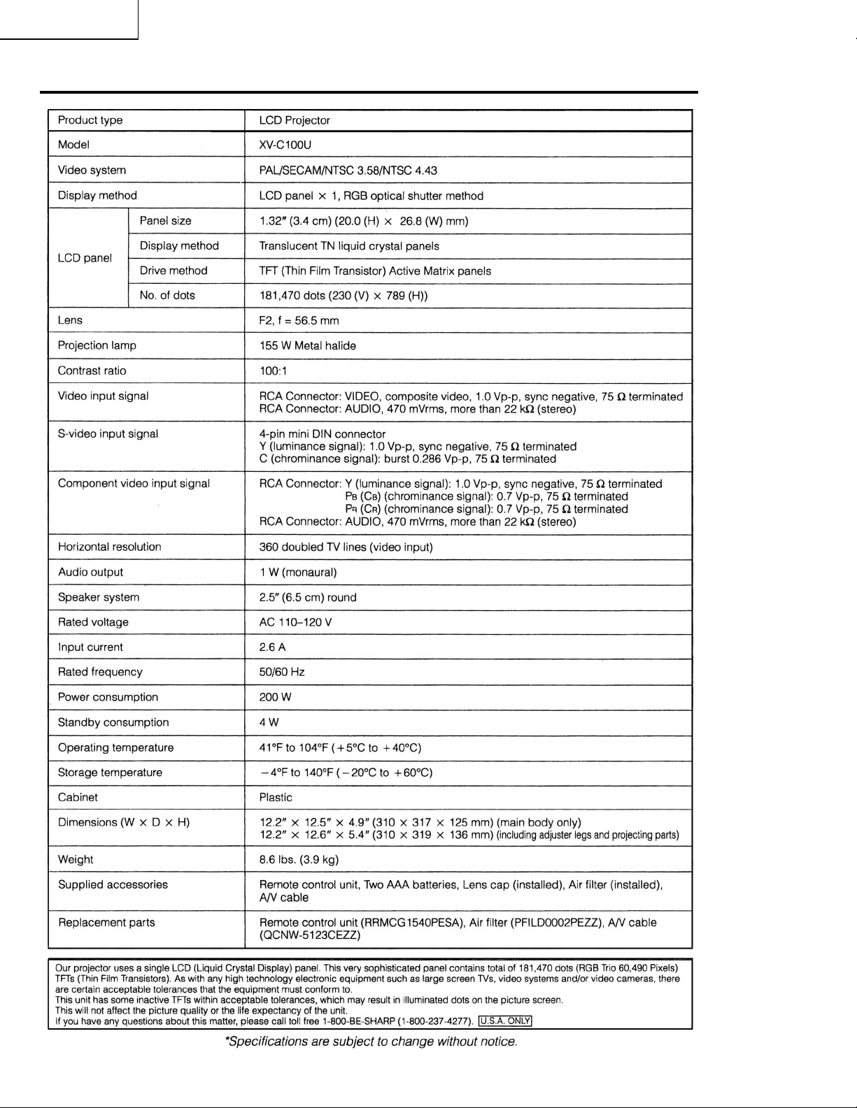
Specifications
2
Page 3
XV-C100U
2
2
2
IMPORTANT SERVICE SAFETY NOTES
Ë
Service work should be performed only by qualified service technicians who are thoroughly
familiar with all safety checks and servicing guidelines as follows:
WARNING
1. For continued safety, no modification of any circuit
should be attempted.
2. Disconnect AC power before servicing.
BEFORE RETURNING THE PROJECTOR:
(Fire & Shock Hazard)
Before returning the projector to the user, perform
the following safety checks:
1. Inspect lead wires are not pinched between the
chassis and other metal parts of the projector.
2. Inspect all protective devices such as non-metallic
control knobs, insulating materials, cabinet backs,
adjustment and compartment covers or shields,
isolation resistor-capacity networks, mechanical
insulators, etc.
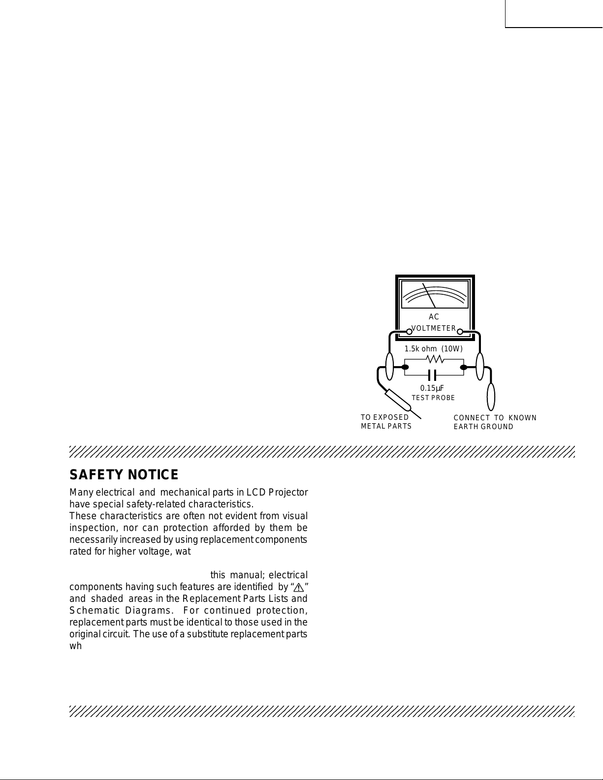
3. To be sure that no shock hazard exists, check for
current leakage in the following manner:
» Plug the AC cord directly into a 120-volt AC outlet,
(Do not use an isolation transformer for this test).
» Using two clip leads, connect a 1.5k ohm, 10 watt
resistor paralleled by a 0.15µF capacitor in parallel
between all exposed metal cabinet parts and earth
ground.
» Use an AC voltmeter with sensitivity of 5000 ohm per
volt., or higher , sensitivity to measure the AC voltage
drop across the resistor (See Diagram).
» All checks must be repeated with the AC plug
connection reversed. (If necessary, a non-polarized
adapter plug must be used only for the purpose of
completing these checks.)
Any reading of 0.3 volts RMS (this corresponds to
0.2 milliamp. A C.) or more is e xcessive and indicates
a potential shock hazard which must be corrected
before returning the unit to the owner.
AC
VOLTMETER
1.5k ohm (10W)
0.15µF
TEST PROBE
TO EXPOSED
METAL PARTS
CONNECT TO KNOWN
EARTH GROUND
234567890123456789012345678901212345678901234567890123456789012123456789012345678901234567890121
234567890123456789012345678901212345678901234567890123456789012123456789012345678901234567890121
SAFETY NOTICE
Many electrical and mechanical parts in LCD Projector
have special safety-related characteristics.
These characteristics are often not evident from visual
inspection, nor can protection afforded by them be
necessarily increased by using replacement components
rated for higher voltage, wattage, etc.
Replacement parts which have these special safety
characteristics are identified in this manual; electrical
components having such features are identified b y “å”
and shaded areas in the Replacement Parts Lists and
Schematic Diagrams. For continued protection,
replacement parts must be identical to those used in the
original circuit. The use of a substitute replacement parts
which do not have the same safety characteristics as
the factory recommended replacement parts shown in
this service manual, may create shock, fire or other
hazards.
AVIS POUR LA SECURITE
De nombreuses pièces, électriques et mécaniques, dans
les projecteur à LCD présentent des caractéristiques
spéciales relatives à la sécurité, qui ne sont souvent
pas évidentes à vue.
Le degré de protection ne peut pas être nécessairement
augmentée en utilisant des pièces de remplacement
étalonnées pour haute tension, puissance, etc.
Les pièces de remplacement qui présentent ces
caractéristiques sont identifiées dans ce manuel;
les pièces électriques qui présentent ces particular ités
sont identifiées par la marque “å” et hachurées dans la
liste des pièces de remplacement et les diagrammes
schématiques. Pour assurer la protection, ces pièces
doivent être identiques à celles utilisées dans le circuit
d’origine. L’utilisation de pièces qui n’ont pas les mêmes
caractéristiques que les pièces recommandées par
l’usine, indiquées dans ce manuel, peut provoquer des
électrocutions, incendies ou autres accidents.
234567890123456789012345678901212345678901234567890123456789012123456789012345678901234567890121
3
Page 4
XV-C100U
2
NOTE TO SERVICE PERSONNEL
234567890123456789012345678901212345678901234567890123456789012123456789012345678901234567890121
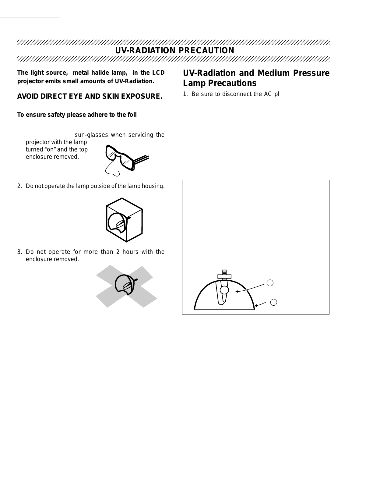
The light source, metal halide lamp, in the LCD
projector emits small amounts of UV-Radiation.
AV OID DIRECT EYE AND SKIN EXPOSURE.
To ensure safety please adhere to the following:
1. Be sure to wear sun-glasses when servicing the
projector with the lamp
turned “on” and the top
enclosure removed.
2. Do not operate the lamp outside of the lamp housing.
UV-RADIATION PRECAUTION
UV-Radiation and Medium Pressure
Lamp Precautions
1. Be sure to disconnect the AC plug when replacing
the lamp.
2. Allow one hour for the unit to cool down before
servicing.
3. Replace only with same type lamp. Type
CLMPF0053DE05 rated 65V/155W.
4. The lamp emits small amounts of UV-Radiation,
avoid direct-eye contact.
5. The medium pressure lamp involves a risk of
explosion. Be sure to follow installation instructions
described below and handle the lamp with care.
Ë
Lamp Replacement
Note:
Since the lamp reaches a very high temperature
during units operation replacement of the lamp
should be done at least one hour after the power
has been turned off. (to allow the lamp to cool off.)
Installing the new lamp, make sure not to touch the
lamp (bulb) replace the lamp by holding its reflector
3. Do not operate for more than 2 hours with the
enclosure removed.
2.
[Use original replacement only.]
Lamp
1
Reflector
2
DANGER ! –– Never turn the power on without the
lamp to avoid electric-shock or damage of the de vices
since the stabilizer generates high voltages at its
start.
4
Page 5
XV-C100U
2
2
234567890123456789012345678901212345678901234567890123456789012123456789012345678901234567890121
234567890123456789012345678901212345678901234567890123456789012123456789012345678901234567890121
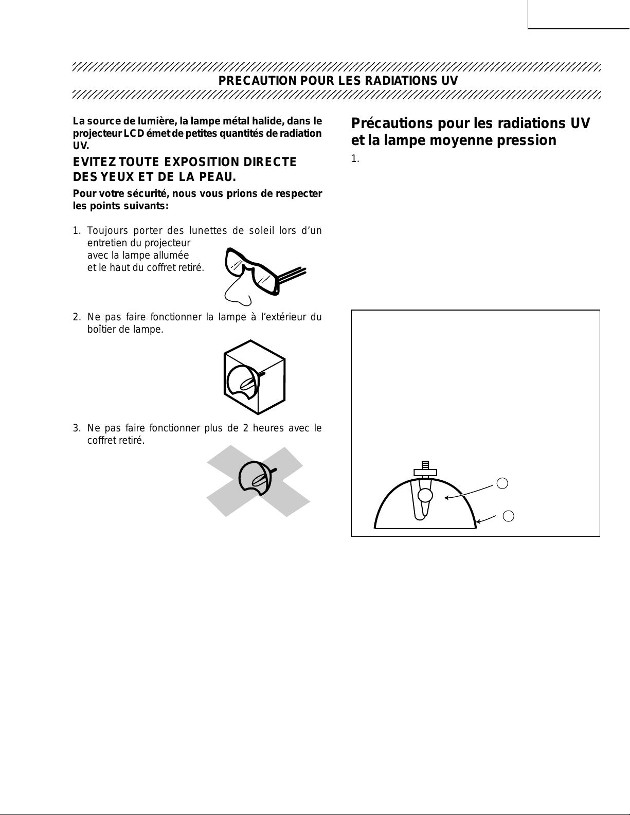
La source de lumière, la lampe métal halide, dans le
projecteur LCD émet de petites quantités de radiation
UV.
EVITEZ TOUTE EXPOSITION DIRECTE
DES YEUX ET DE LA PEAU.
Pour votre sécurité, nous vous prions de respecter
les points suivants:
NOTE POUR LE PERSONNEL D’ENTRETIEN
PRECAUTION POUR LES RADIATIONS UV
Précautions pour les radiations UV
et la lampe moyenne pression
1. Toujours débrancher la fiche AC lors du
remplacement de la lampe.
2. Laisser l’unité refroidir pendant une heure avant de
procéder à l’entretien.
3. Ne remplacer qu’avec une lampe du même type.
Type CLMPF0053DE05 caractéristique 65V/155W.
1. Toujours porter des lunettes de soleil lors d’un
entretien du projecteur
avec la lampe allumée
et le haut du coffret retiré.
4. La lampe émet de petites quantités de radiation UV -
éviter tout contact direct avec les yeux.
5. La lampe moyenne pression implique un risque
d’explosion. Toujours suivre les instructions
d’installation décrites ci-dessous et manipuler la
lampe avec soin.
2. Ne pas faire fonctionner la lampe à l’extérieur du
boîtier de lampe.
Ë
Remplacement de la lampe
Remarque:
Comme la lampe devient très chaude pendant le
fonctionnement de l’unité, son remplacement ne doit
être effectué au moins une heure après avoir coupé
l’alimentation (pour permettre à la lampe de refroidir).
En installant la nouvelle lampe, s’assurer de ne pas
toucher la lampe (ampoule). Remplacer la lampe en
3. Ne pas faire fonctionner plus de 2 heures avec le
coffret retiré.
tenant son réflecteur 2.
[N’utiliser qu’un remplacement d’origine.]
Lampe
1
2
Reflecteur
DANGER ! –– Ne jamais mettre sous tension sans
la lampe pour éviter un choc électrique ou des
dommages des appareils car le stabilisateur génère
de hautes tensions à sa mise en route.
5
Page 6
XV-C100U
2
WARNING: High brightness light source. Do not stare into the beam of light, or view directl y . Be especially
careful that children do not stare directly into the beam of light.
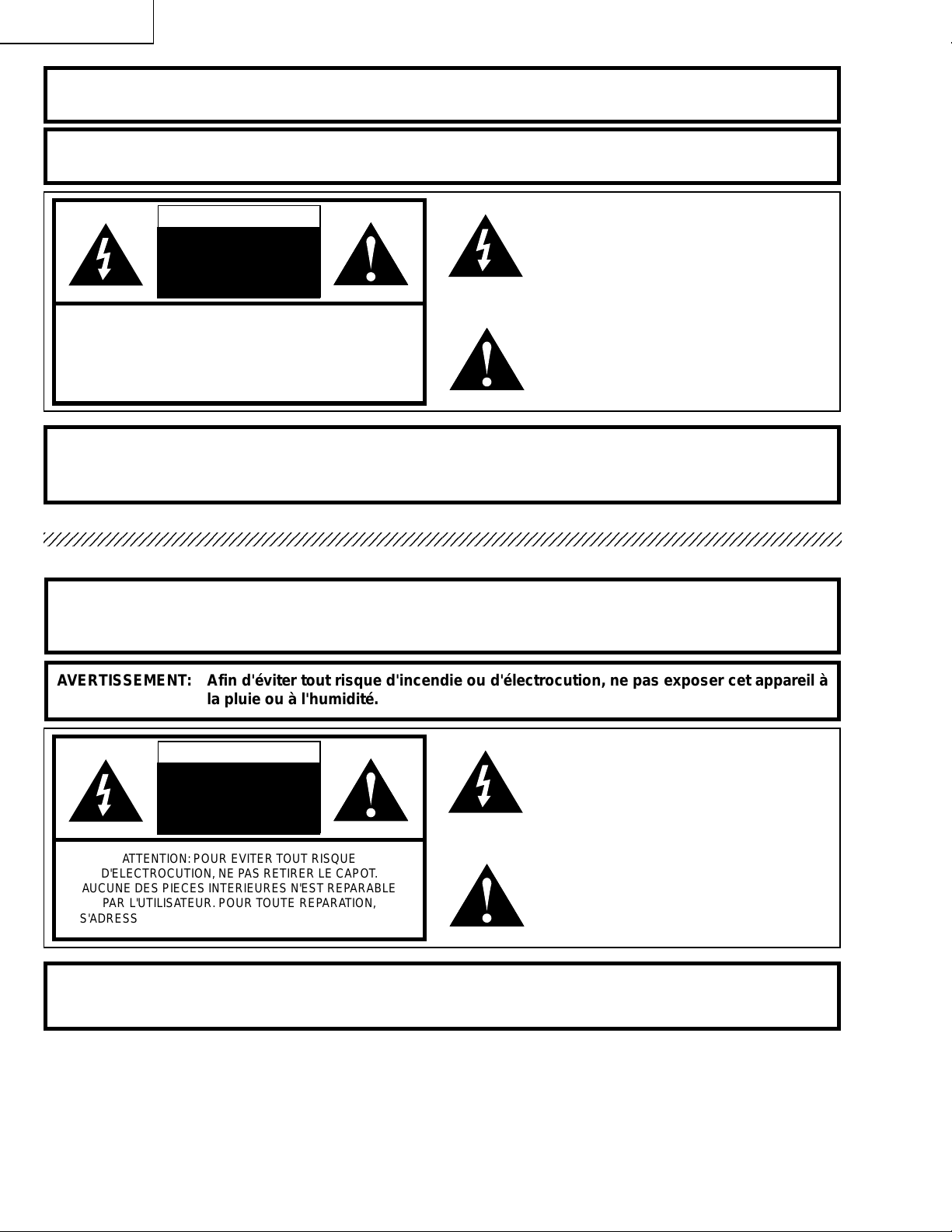
WARNING: To reduce the risk of fire or electric shock, do not expose this product to rain or moisture.
CAUTION
RISK OF ELECTRIC
SHOCK.
DO NOT OPEN.
CAUTION: TO REDUCE THE RISK OF ELECTRIC SHOCK,
DO NOT REMOVE CABINET.
NO USER-SERVICEABLE PARTS.
REFER SERVICING TO QUALIFIED SERVICE
PERSONNEL.
The lightning flash with arrowhead symbol,
within an equilateral triangle, is intended to alert
the user to the presence of uninsulated
"dangerous voltage" within the product's
enclosure that may be of sufficient magnitude
to constitute a risk or electric shock to persons.
The exclamation point within a triangle is
intended to alert the user to the presence of
important operating and maintenance
(servicing) instructions in the literature
accompanying the product.
WARNING: The bimetallic component has the primary conductive side exposed. Be very careful in
handling this component when the power is on.
234567890123456789012345678901212345678901234567890123456789012123456789012345678901234567890121
A VERTISSEMENT: Source lumineuse de grande intensité. Ne pas fixer le faisceau lumineux ou le regarder
directement. Veiller particulièrement à éviter que les enfants ne fixent directement le
faisceau lumineux.
AVERTISSEMENT: Afin d'éviter tout risque d'incendie ou d'électrocution, ne pas exposer cet appareil à
la pluie ou à l'humidité.
ATTENTION
RISQUE CHOC
ELECTRIQUE—
NE PAS OUVRIR.
ATTENTION: POUR EVITER TOUT RISQUE
D'ELECTROCUTION, NE PAS RETIRER LE CAPOT.
AUCUNE DES PIECES INTERIEURES N'EST REPARABLE
PAR L'UTILISATEUR. POUR TOUTE REPARATION,
S'ADRESSER A UN TECHNICIEN D'ENTRETIEN QU ALIFIE.
L'éclair terminé d'une flèche à l'intérieur d'un
triangle indique à l'utilisateur la présence à
l'intérieur de l'appareil d'une «tension
dangereuse» non isolée ayant une amplitude
suffisante pour provoquer une électrocution.
Le point d'exclamation à l'intérieur d'un triangle
indique que des instructions de fonctionnement
et d'entretien importantes sont détaillées dans
les documents fournis avec l'appareil.
A VER TISSEMENT : La composante bimétallique dispose du conducteur primaire dénudé. Faire attention
lors de la manipulation de cette composante sous tension.
6
Page 7

Location of Controls
XV-C100U
7
Page 8
XV-C100U
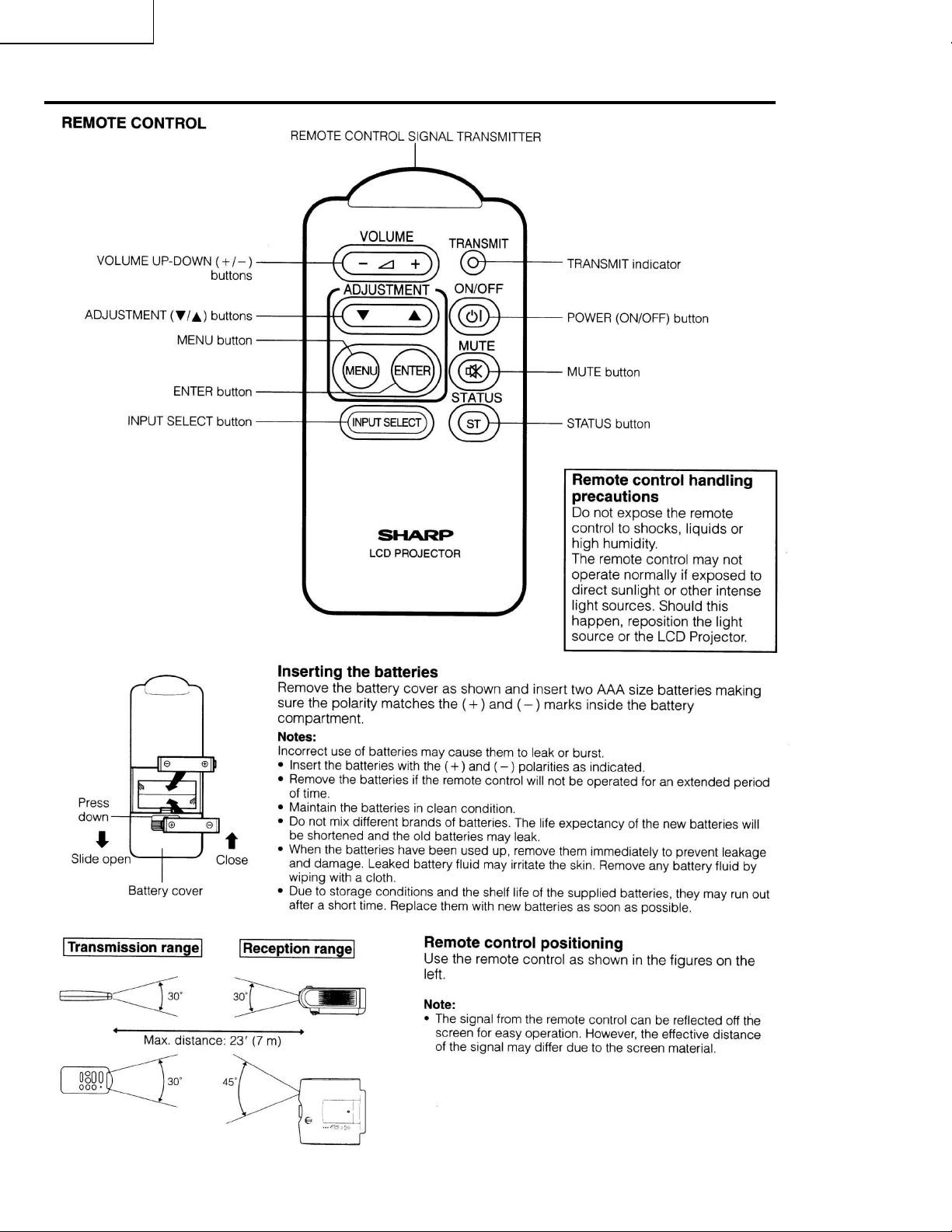
Remote Control Operation
8
Page 9

Dimensions
XV-C100U
9
Page 10
XV-C100U
Rear Cabinet
1-4
1-5
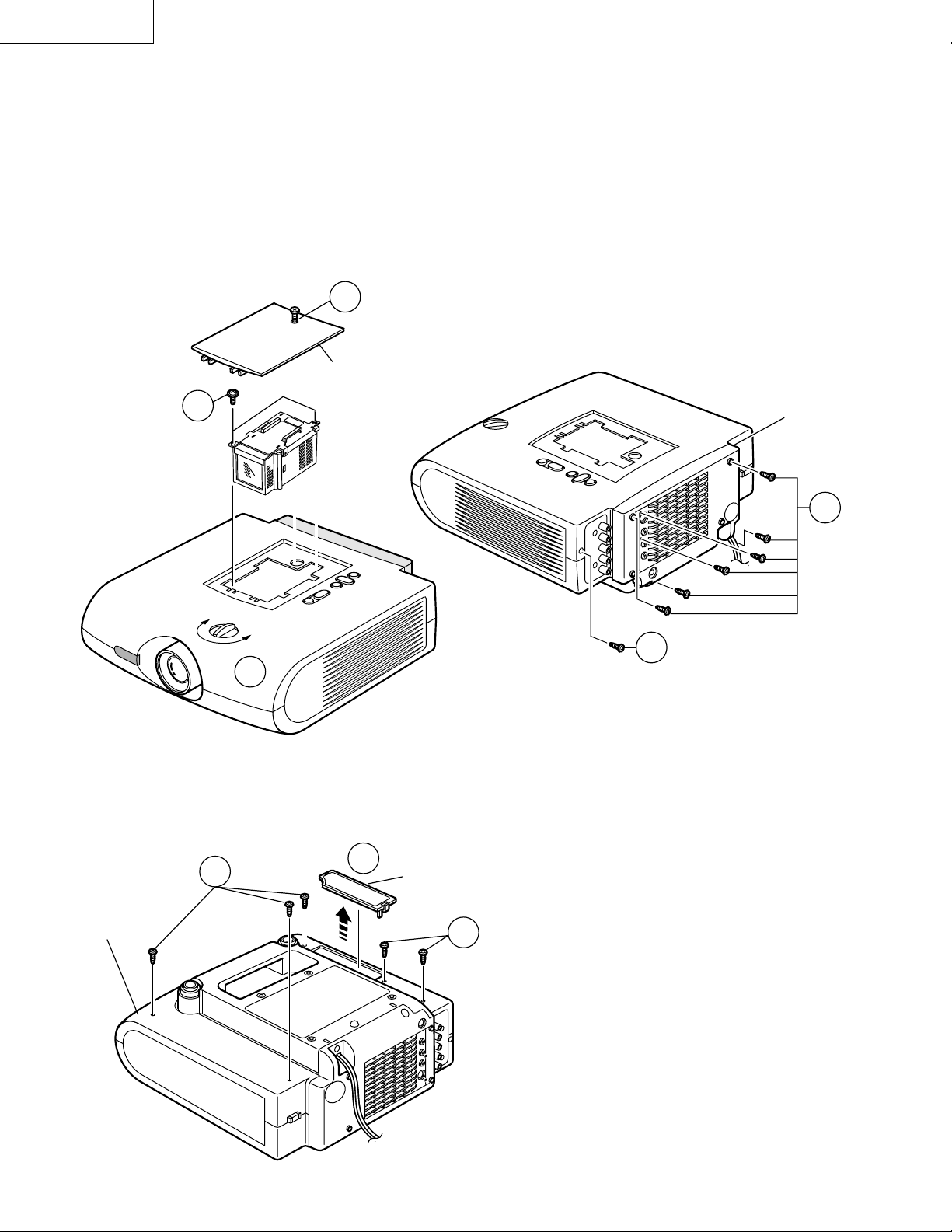
REMOVAL OF MAJOR COMPONENTS
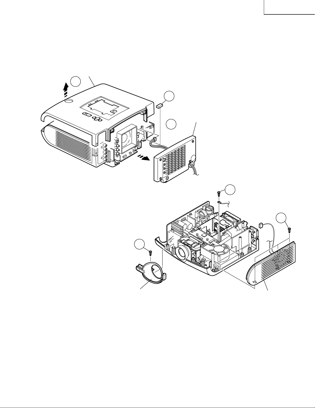
1. Removing the cabinets
1-1. Remove the screw and detach the lamp cage cover.
1-2. Remove the two lock screws (two 4-mm screws) off the lamp/cage module unit.
1-3. Turn the lens shift dial until the lens comes to almost the center of the lens hole in the front cabinet.
1-4. Remove the six screws (six 3-mm tapping screws) off the rear cabinet.
1-5. Remove the M3 tapping screw off the sub unit cover.
1-1
Lamp Cage Cover
1-2
Lamp/Cage Module Unit
1-3
1-6. Remove the air filter cover.
1-7. Remove the five tapping screws off the bottom cabinet.
1-7
Bottom Cabinet
1-6
Air Filter Cover
1-7
10
Page 11
Top Cabinet
1-8
1-10
(PE)
XV-C100U
1-8. Now lift the top cabinet further up and
disconnect the leaf switch connectors (LL) as
well as the operation key unit flat cable (KE).
The top cabinet is now free.
1-9. Disconnect the connector (PE) of the AC cord
(that runs through the rear cabinet) from the
ballast unit. Detach the rear cabinet.
1-10. Remove the spacer.
1-11. Remove the screws off the lens Cover.
1-12. Disconnect the speaker connector (SP) and
remove the three lock screws. Remove the
screw off the ground lead. Now detach the side
cover.
Rear Cabinet
1-9
1-12
1-11
Lens Cover
Reassembling procedure
1. Fit the lens cover and the side cover to the bottom panel. Tighten up the related screws.
2. Set the top cabinet over the bottom cabinet.
3. Tighten up the M3 tapping screw into the sub unit cover.
(SP)
Side Cover
1-12
4. Press the rear cabinet against the top and bottom cabinets to fit them together.
5. Tighten up the screws into the rear cabinet. Use the six 3-mm tapping screws.
6. Tighten up the tapping screws to fix the top and bottom cabinets.
7. Put the lamp/cage module unit into position. Tighten up the two 4-mm screws.
8. Place the lamp cage cover and tighten up the screws.
11
Page 12
XV-C100U
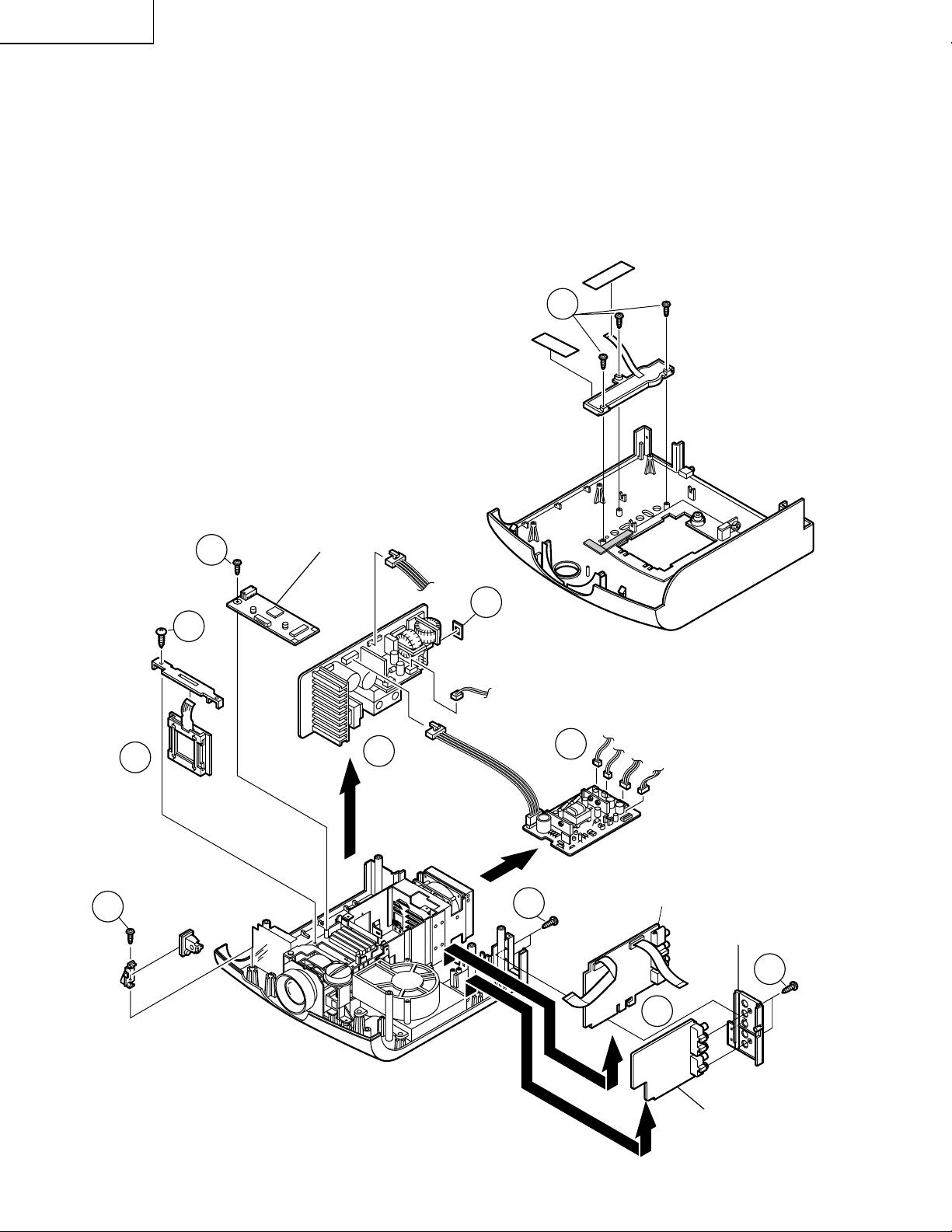
2. Removing the PWBs
2-1. Slide out the power unit, ballast unit, main unit in their directions of arrow. Disconnect the connectors.
2-2. Remove the three screws, peel off the two pieces of tape, and take out the operation key unit.
2-3. Remove the screws off the control unit and R/C Receiver unit and sub unit. Disconnect the connectors.
2-4. Remove the button cover.
3. Removing the LCD module unit
3-1. Remove the screw off the panel cover. Take out the panel cover.
3-2. Pull up the LCD module unit slowly out of position.
2-2
Operation Key Unit
Panel Cover
3-2
2-3
2-3
3-1
LCD
Module Unit
R/C Receiver
Unit
Control Unit
2-1
2-4
Ballast Unit
2-3
Top Cabinet
2-1
Power Unit
Main Unit
Sub Unit Cover
2-3
12
2-1
Sub Unit
Page 13
XV-C100U
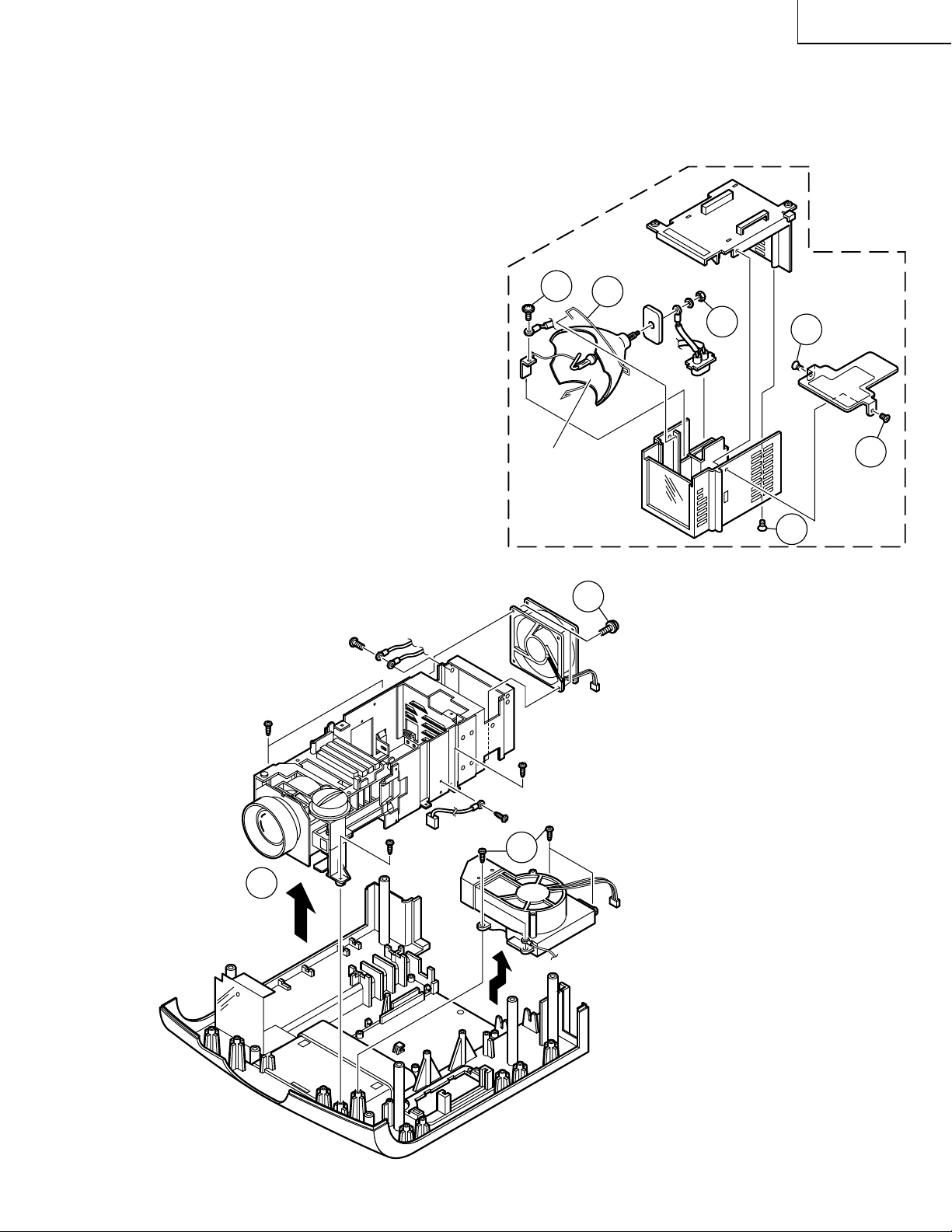
4. Removing the optics mechanism assembly
4-1. Remove the four screws off the optics mechanism assembly. Detach the assembly from the bottom cabinet.
4-2. Remove the four screws off the intake duct assembly. Detach the intake duct assembly from the bottom
cabinet.
4-3. Remove the two screws off the cooling fan.
5.Removing the lamp
5-1. Remove the three countersunk lock screws off
the upper and lower lamp cases.
5-2. Remove the lock screw and the nut off the lamp
terminal.
5-3. Release the lamp lock spring off the hook below
the lower lamp case. Take out the lamp/mirror
assembly.
5-2
Lamp/Mirror
Ass’y
Lower Lamp Case
5-3
4-3
5-2
Lamp/Cage
Module Unit
Upper Lamp
Case
5-1
5-1
5-1
Optics Mecha
Ass’y
Bottom Cabinet Ass’y
Cooling Fan
(Exhaust Vent)
4-2
4-1
Intake Duct Ass’y
13
Page 14
XV-C100U
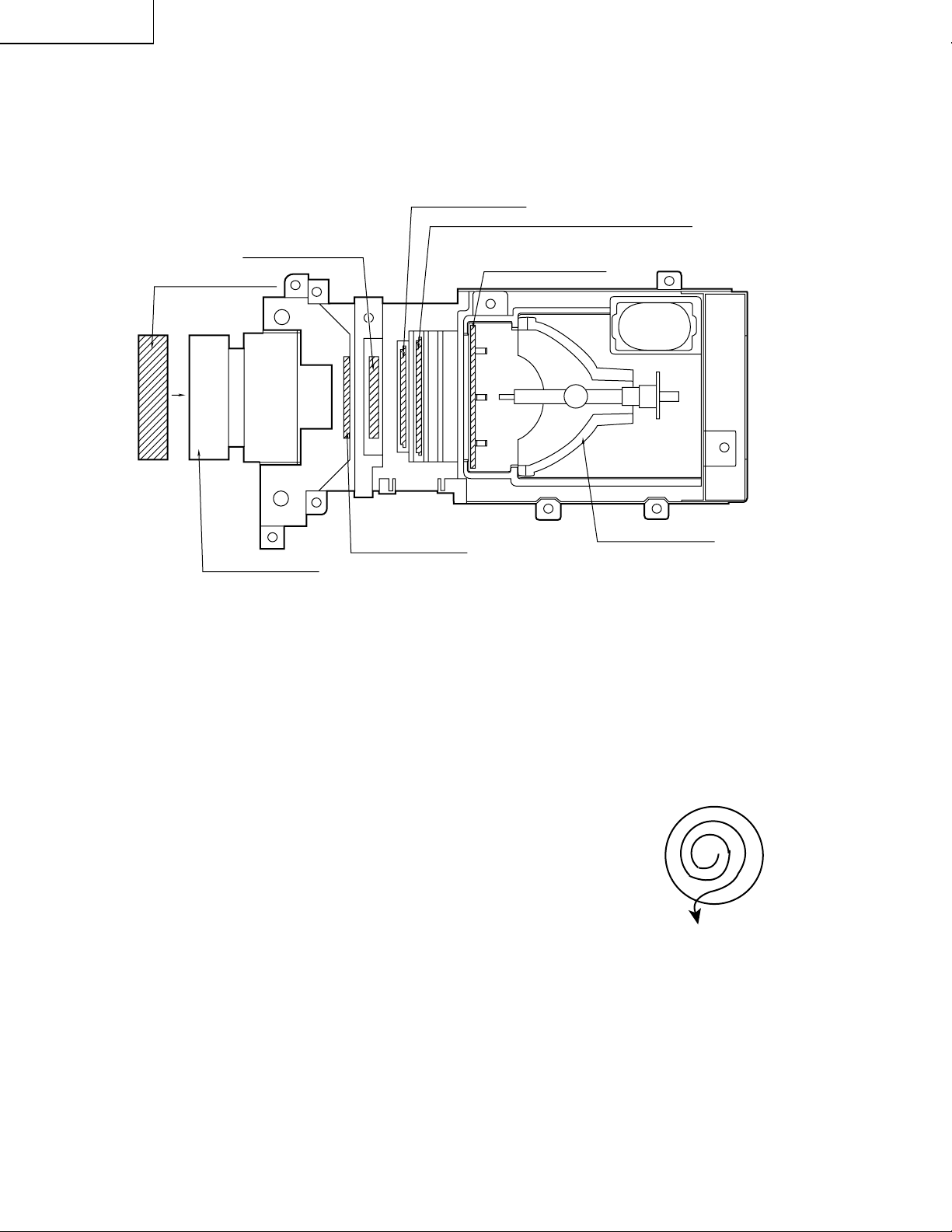
Optical unit
RLCDP0088CEZZ
PCAPH1061CESB
Lens cap
OPTICAL SYSTEM
Polarizer Input plate
PFiLW0164CEZZ
PFiLW0202CEZZ
LCD
PFiLW0194CEZZ
Heat Management plate
UV/IR filter
PFiLW0200CEZZ
PLNS-0124CEZZ
Projection lens
Ë
Cleaning the lenses and reflectors
Diffraction grating
1. Lens cleaner
• Cleaning liquid:
Change the mixture ratio of alcohol and ether depending on ambient
temperatures. Make sure that the liquid evaporates from the lens
surface immediately after you rub it: This is the best ratio. The more
ether is used, the quicker the liquid evaporates.
• Method:
Use well-washed bleached cotton cloth or cleaning paper available
on the market. Damp the bleached cotton cloth with the liquid, and
hold the lens sandwiched in the cloth with your thumb and the index
finger. Tur n the lens and wipe the surface clean from the center
outward to collect dust. Be careful not to rub the coated surface too
strong.
CLMPF0053DE05
Lamp/Mirror Ass'y
14
Page 15

Ë
Controlling the total operating hours of the lamp
The following control is carried out when the lamp has been used for 1,900 hours and 2,000 hours.
1. After 1,900-hour use
When the power is turned on, "LAMP" appears in the on-screen display for about 1 minute (flashing in yellow)
and the lamp LED indicator lights up in red.
When the 1,900-hour point comes up during use of the unit, the "LAMP" display starts flashing in yellow on the
screen for 1 minute at the very 1,900-hour point.
Now the lamp LED indicator changes from green to red.
2. After 2,000-hour use
When the power is turned on, "LAMP" appears in the on-screen display for 5 minutes (flashing in red) and the
lamp LED indicator lights up in red. Five min utes thereafter , the po wer turns itself off and the unit is interrupted.
When the 2,000-hour point comes up during use of the unit, the "LAMP" display starts flashing in red on the
screen for 5 minutes at the very 2,000-hour point. Five minutes later, the power turns itself off and the unit is
interrupted. (The lamp LED indicator stays red since the 1,900-hour point.)
If you try to turn on the power twice after the 2,000-hour point, the unit remains off.
3. When the 2000-hour point comes up, take the following steps.
Replace the lamp with new one. While holding down both the "VOLUME "" and "SELECT/ADJ "" Keys on the
unit, turn on the main power switch (located on the back of the unit). The lamp operating hourmeter is now reset
to zero. Tur n on the unit and make sure the time display shows "0000H".
XV-C100U
4. Displaying the total operating hours of the lamp
Change the STATUS3 data settings: PICTURE at 0, BRIGHT at MAX, COLOR at MIN, TINT at MIN, and
SHARPNESS at MAX. Hold down the SOUND DOWN and ENTER keys for longer than 2 seconds. By doing
this, the total operating hours will be displayed on the screen.
TIME
0000H
TOTAL TIME
0000H
15
Page 16
XV-C100U
ADJ IN (adjustment input) FUNCTION
1. Keys used for the adjustments
On the sub PWB: S2001
Control keys: [ENTER], [MENU], [SELECT/ADJ.'], [SELECT/ADJ."], [VOLUME+]
2. Operation
Press S2001 to call up the ADJ IN mode.
Use the [SELECT/ADJ. '] and [SELECT/ADJ."] keys to select an adjustment group, and press the
[ENTER] key.
Use the [SELECT/ADJ. '] and [SELECT/ADJ."] keys again to select an adjustment subject, and
press the [ENTER] key.
The [SELECT/ADJ. '] and [SELECT/ADJ."] keys are also used to make adjustments.
Each time the [ENTER] key is pressed on the ADJ IN screen, the adjustment subjects of a group are
changed one by one. (Pressing the [VOLUME + ] key changes the subjects in the reverse order.)
When the [MENU] key is pressed, the previous group appears on the screen.
Press S2001 again to go out of the ADJ IN mode.
Group
Adjustment
subjects
VIDEO 1
H-CENT
P-H-CENT
CONT
BRIGHT
SUB-R
SUB-G
SUB-B
VIDEO 2
SUB-BIAS
R-BIAS
B-BIAS
R-DRIVE
B-DRIVE
TINT
COLOR
P-COLOR
S-COLOR
VIDEO 3
GAMMA1
GAMMA2
AGCADJ
T-BRT
VIDEO 4
C-CONT
C-BRIGHT
C-COLOR
C-TINT
C-H-CENT
C-PH-CENT
SET
HL
The adjustment group "LINE" is not used here.
Do not feed the signal when the adjustment group "N • W" is used.
N • W
RED
GREEN
BLUE
N • W
LINE
AUTO
OFF TIMER
TEMP1
TEMP2
FACTORY SET4
TEST
TIME1
TIME2
16
Page 17

3. Adjustment subjects
VIDEO 1
H-CENT NTSC horizontal position adjustment
P-H-CENT PAL horizontal position adjustment
CONT Sub-contrast adjustment
BRIGHT Brightness adjustment
SUB-R Not used, just to be 0 (zero)
SUB-G Not used, just to be 0 (zero)
SUB-B Not used, just to be 0 (zero)
VIDEO 2
SUB-BIAS Sub-bias adjustment
R-BIAS White balance (red), bias adjustment
B-BIAS White balance (blue), bias adjustment
R-DRIVE White balance (red), drive adjustment
B-DRIVE White balance (blue), drive adjustment
TINT TINT adjustment
COLOR Color level adjustment
P-COLOR PAL color level adjustment
S-COLOR SECAM color level adjustment
XV-C100U
VIDEO 3
GAMMA1 Gamma correction 1
GAMMA2 Gamma correction 2
AGC ADJ AGC adjustment
T-BRT Chroma IC brightness adjustment
VIDEO 4
C-CONT Component input contrast adjustment
C-BRIGHT Component input brightness adjustment
C-COLOR Component input color level adjustment
C-TINT Component input tint adjustment
C-H-CENT Component input NTSC horizontal position adjustment
C-PH-CENT Component input PAL horizontal position adjustment
SET
HL Temperature detection level setting
N • W (Single-color display)
RED Red
GREEN Green
BLUE Blue
N • W Not used
TEST
TIME1 1-hour increment setting for total lamp timer
TIME2 1899H-1999H-0H-1899H setting for total lamp timer
17
Page 18
XV-C100U
18
User mode screen
S2001
ADJ IN
VIDEO1 SET
VIDEO2 N • W
VIDEO3 LINE
VIDEO4 TEST
ENTER
VIDEO1
H-CENT SUB-R
P-H-CENT SUB-G
CONT SUB-B
BRIGHT
VIDEO2
SUB-BIAS
R-BIAS
B-BIAS
R-DRIVE
B-DRIVE
MENU
VIDEO3
GAMMA1
GAMMA2
AGC ADJ
T-BRT
VIDEO4
N • W
C-CONT
C-BRIGHT
C-COLOR
C-TINT
C-H-CENT
RED
GREEN
BLUE
N • W
C-PH-CENT
TINT
COLOR
P-COLOR
S-COLOR
ENTER
MENU
ENTER
MENU
ENTER
MENU
ENTER
MENU
ENTER
MENU
H-CENT
–3
SUB-BIAS
64
GAMMA1
255
C-CONT
–4
RGBN • W
P-H-CENT
GAMMA2
C-BRIGHT
0
R-BIAS
CONT
+6
AGC
ADJ
B-BIAS
0
C-COLOR
74
0
+5
74
T-BRT
–30
+7
BRIGHT
–3
R-DRIVE
C-TINT
Not used
64
+9
SUB-R
TINT
–3
0
SUB-G
B-DRIVE
COLOR
C-H-CENT
0
64
–4
+5
C-PH-CENT
HL
2
SUB-B
P-COLOR
0
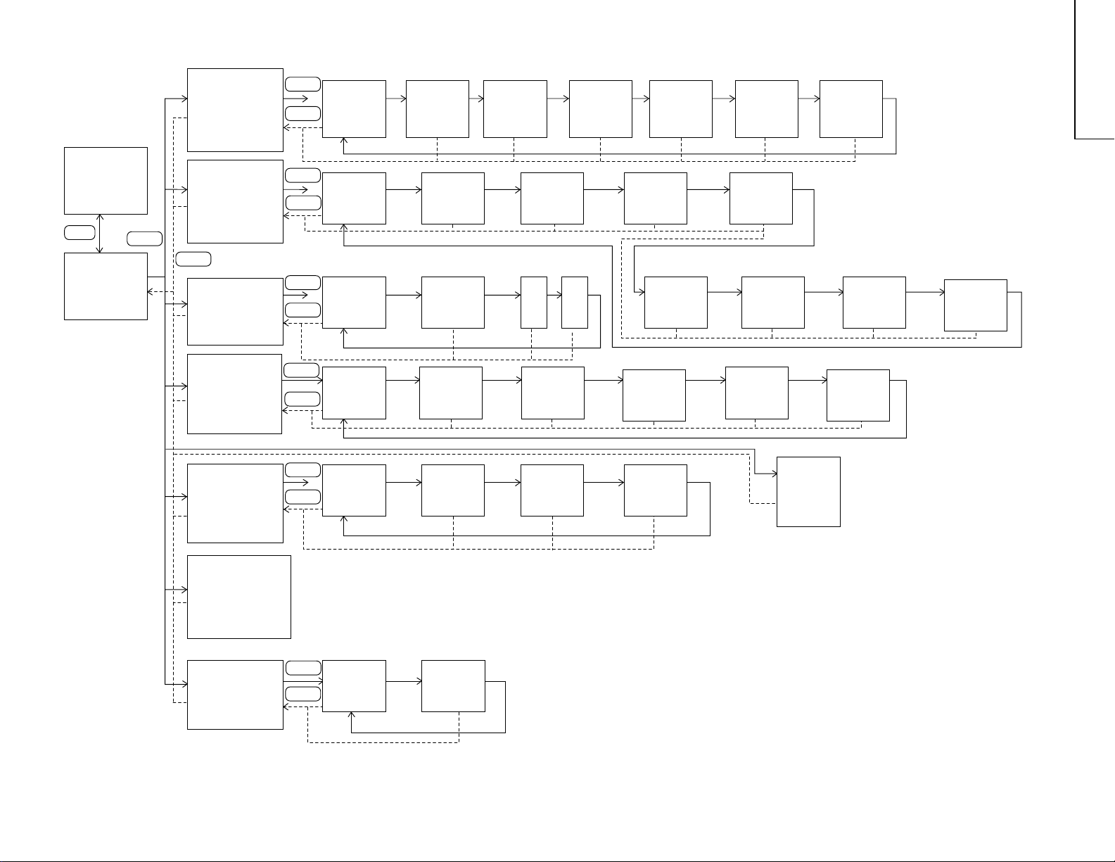
FLOWCHART OF ADJUSTMENT
–6
+7
S-COLOR
–4
LINE
AUTO
OFF TIMER
TEMP1
TEMP2
FACTORY SET 4
Not used
TEST
TIME1
TIME2
ENTER
MENU
TIME1
0001
TIME2
0000
Page 19
XV-C100U
ELECTRICAL ADJUSTMENT
No. Adjustment Item Adjustment Conditions Adjustment Procedure
1
NTSC freerunning
frequency
(R1616)
2
PAL freerunning
frequency
(R1602)
3
Horizontal
center (NTSC)
(DAC)
4
Horizontal
center (PAL)
(DAC)
1.Receive the NTSC monoscope pattern
signal.
2.Hold down S801.
1. Receive the PAL monoscope pattern
signal.
2. Hold down S801.
1. Receive the NTSC monoscope pattern
signal.
2. Press S2001 to call up the ADJ IN
mode and select the following subject.
Group: VIDEO 1
Subject: H-CENT
1. Receive the PAL monoscope pattern
signal.
2. Press S2001 to call up the ADJ IN
mode and select the following subject.
Group: VIDEO 1
Subject: P-H-CENT
• T urn R1616 until the image appears
as specified.
• T urn R1602 until the image appears
as specified.
• Using the ' and " keys, make the
overscan just the same at right and
left.
Overscan: 91-97%
• Using the ' and " keys, make the
overscan just the same at right and
left.
Overscan: 91-97%
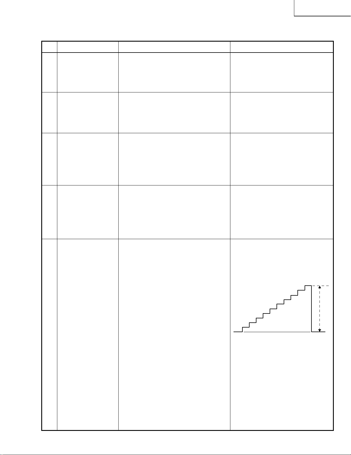
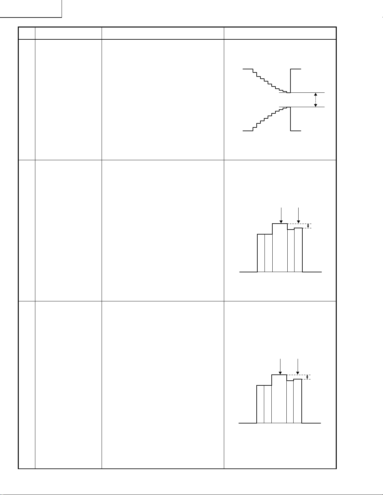
5
Contrast (DAC)
(gamma
correction off)
1. Receive the NTSC 10-step pattern
signal.
2. Connect a dual-beam oscilloscope
between pin (2) of P1401 and GND.
3. Press S2001 to call up the ADJ IN
mode and select the following subject.
Group: VIDEO 2
Subject: SUB-BIAS
4. Using the ' and " keys, put the
waveform to its proper shape.
5. Press S2001 again to call up the ADJ
IN mode and select the following
subject.
Group: VIDEO 1
Subject: SUB-R, SUB-G, SUB-B
Make sure all these subjects have an
entry of 0 (zero).
6. Adjust R861 to get the highest gain.
7. Finally select the following subject.
Group: VIDEO 1
Subject: CONT
• Using the ' and " keys, adjust the
difference between the tenth-step
level and the pedestal level to
6.0±0.15 Vp-p.
10
19
Page 20
XV-C100U
No. Adjustment Item Adjustment Conditions Adjustment Procedure
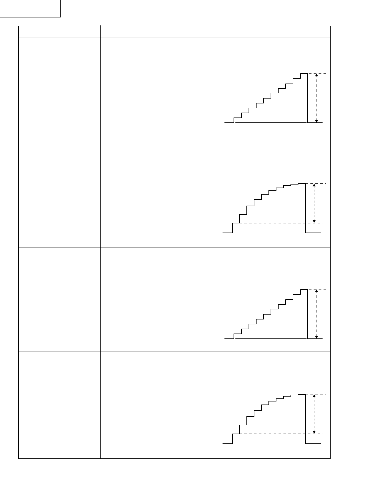
6
Automatic gain
control: R861
(gamma
correction off)
7
Brightness
(DAC)
(gamma
correction on)
1. Receive the NTSC 10-step pattern
signal.
2. Connect the dual-beam oscilloscope
between pin (2) of P1401 and GND.
3. Select the following subject.
Group: VIDEO 1
Subject: CONT
1. Receive the NTSC 10-step pattern
signal.
2. Connect the dual-beam oscilloscope
between pin (2) of P1401 and GND.
3. Press S2001 to call up the ADJ IN
mode and select the following subject.
Group: VIDEO 1
Subject: BRIGHT
• Turn R861 so that the difference
between the tenth-step level and the
pedestal level be 4.8±0.05 Vp-p.
10
• Using the ' and " keys, adjust the
difference between the first-step
level and the tenth-step level to
2.0±0.05 Vp-p.
10
1
8
Component
contrast (DAC)
(gamma
correction off)
9
Component
brightness
(DAC)
(gamma
correction on)
1. Feed the NTSC 10-step pattern signal
to the component terminal.
2. Connect the dual-beam oscilloscope
between pin (2) of P1401 and GND.
3. Press S2001 to call up the ADJ IN
mode and select the following subject.
Group: VIDEO 4
Subject: C-CONT
1. Feed the NTSC 10-step pattern signal
to the component terminal.
2. Connect the dual-beam oscilloscope
between pin (2) of P1401 and GND.
3. Press S2001 to call up the ADJ IN
mode and select the following subject.
Group: VIDEO 4
Subject: C-BRIGHT
• Using the ' and " keys, adjust the
difference between the tenth-step
level and the pedestal level be
4.8±0.05 Vp-p.
10
• Using the ' and " keys, adjust the
difference between the first-step
level and the tenth-step level to
2.0±0.05 Vp-p.
10
1
20
Page 21

XV-C100U
No. Adjustment Item Adjustment Conditions Adjustment Procedure
10
Tint (DAC)
11
Component tint
(DAC)
1. Receive the NTSC half-color bar signal.
2. Press S2001 to call up the ADJ IN
mode and select the following subject.
Group: VIDEO 2
Subject: TINT
3. Connect the dual-beam oscilloscope
between pin (5) of P803 and GND.
1. Feed the NTSC half-color bar signal to
the component terminal.
2. Press S2001 to call up the ADJ IN
mode and select the following subject.
Group: VIDEO 4
Subject: C-TINT
3. Connect the dual-beam oscilloscope
between pin (3) of P803 and GND.
• Using the ' and " keys, adjust the
(B-Y) signal waveform to slope down
straight.
• Using the ' and " keys, adjust the
(B-Y) signal waveform to slope down
straight.
12
Sub-bias (DAC)
(gamma
correction on)
13
R-drive
B-drive
1. Receive the NTSC 10-step pattern
signal.
2. Connect the dual-beam oscilloscope
between pin (2) of P1401 and GND.
3. Press S2001 to call up the ADJ IN
mode and select the following subject.
Group: VIDEO 2
Subject: SUB-BIAS
1. Receive the NTSC 10-step pattern
signal.
2. Connect the dual-beam oscilloscope
between pin (3)(R) (or pin (1)(B)) of
P1401 and GND.
3. Press S2001 to call up the ADJ IN
mode and select the following subject.
Group: VIDEO 2
Subject: R-DRIVE, B-DRIVE
• Using the ' and " keys, adjust the
difference between the white levels
to 3.0±0.05 Vp-p.
• Using the ' and " keys, adjust the
difference between the first-step
level and the tenth-step level to
2.0±0.05 Vp-p.
21
Page 22
XV-C100U
No. Adjustment Item Adjustment Conditions Adjustment Procedure
14 • Using the ' and " keys, adjust the
R-bias
B-bias
15
NTSC color
(DAC) (gamma
correction on)
1. Receive the NTSC 10-step pattern
signal.
2. Connect the dual-beam oscilloscope
between pin (3)(R) (or pin (1)(B)) of
P1401 and GND.
3. Press S2001 to call up the ADJ IN
mode and select the following subject.
Group: VIDEO 2
Subject: R-BIAS, B-BIAS
1. Receive the NTSC half-color bar signal.
2. Connect the dual-beam oscilloscope
between pin (3) of P1401 and GND.
3. Press S2001 to call up the ADJ IN
mode and select the following subject.
Group: VIDEO 2
Subject: COLOR
difference between the white le v els
to 3.0±0.05 Vp-p.
• Using the ' and " keys, adjust the
difference between the 100% white
level and the primary red level to
0±0.05 Vp-p.
100% white
Primary red
16
PAL color (DAC)
(gamma
correction on)
1. Receive the PAL half-color bar signal.
2. Connect the dual-beam oscilloscope
between pin (3) of P1401 and GND.
3. Press S2001 to call up the ADJ IN
mode and select the following subject.
Group: VIDEO 2
Subject: P-COLOR
22
• Using the ' and " keys, adjust the
difference between the 100% white
level and the primary red level to
0.10±0.05 Vp-p.
100% white
Primary red
Page 23

XV-C100U
No. Adjustment Item Adjustment Conditions Adjustment Procedure
17
SECAM color
(DAC) (gamma
correction on)
18
Component
color (DAC)
1. Receive the SECAM half-color bar
signal.
2. Connect the dual-beam oscilloscope
between pin (3) of P1401 and GND.
3. Press S2001 to call up the ADJ IN
mode and select the following subject.
Group: VIDEO 2
Subject: S-COLOR
1. Feed the NTSC half-color bar signal to
the component terminal.
2. Press S2001 to call up the ADJ IN
mode and select the following subject.
Group: VIDEO 4
Subject: C-COLOR
• Using the ' and " keys, adjust the
difference between the 100% white
level and the red level to 0.10±0.05
Vp-p.
100% white
• Make sure that the setting is 12.
Primary red
19
Counter-bias
(R1402)
20
White balance
(DAC)
1. Receive the NTSC monoscope pattern
signal.
1. Receive the NTSC monoscope pattern
signal.
2. Press S2001 to call up the ADJ IN
mode and select the following subject.
Group: VIDEO 2
Subject: R-BIAS, B-BIAS
• Turn R1402 until the best contrast
is achieved.
• Using the ' and " keys, visually
adjust the white balance to best
position.
23
Page 24

XV-C100U
No. Adjustment Item Adjustment Conditions Adjustment Procedure
21
On-screen
display position
check (L2003)
22
Temperature
sensor setting
check
23
Component
horizontal
center (NTSC)
(DAC)
1. Receive the NTSC monoscope pattern
signal.
2. Press the SOUND UP/DOWN keys to
get the sound volume display bar on
the screen.
1. Press S2001 to call up the ADJ IN
mode and select the following group.
Group: SET
Subject: HL
1. Receive the NTSC monoscope pattern
signal.
2. Press S2001 to call up the ADJ IN mode
and select the following subject.
Group: VIDEO 4
Subject: C-H-CENT
• Tur n L2003 so that the display bar
be well centered on the screen.
• Make sure that the setting is 2.
• Using the ' and " keys, make the
overscan just the same at right and
left.
Overscan: 91-97%
24
Component
horizontal
center (PAL)
(DAC)
1. Receive the PAL monoscope pattern
signal.
2. Press S2001 to call up the ADJ IN
mode and select the following subject.
Group: VIDEO 4
Subject: C-PH-CENT
24
• Using the ' and " keys, make the
overscan just the same at right and
left.
Overscan: 91-97%
Page 25

TROUBLE SHOOTING TABLE
Checking the video system
No picture
XV-C100U
Check the power unit.
Check IC401, DL401 and their
peripheral circuits.
No
No
Is the lamp on?
Yes
Is voltage applied at the EA
and EB connectors?
Yes
Is there signal at pins (21) and
(29) of IC801?
Yes
Is there signal at pins (1), (2) and (3)
of P803?
Yes
Go to "Checking the IC1501
interface circuit".
No
Check the lamp.
Check the ballast unit circuit.
No
Check IC801, IC804, Q801, Q802,
Q803 and their peripheral circuits.
No color or poor tint with
NTSC signal
Is there chroma signal input at pin
(20) of IC801?
Yes
Check IC801, IC802, IC804 and its
peripheral circuits (X801 and C810 in
particular).
25
No
Check DL401, IC401, Q401 and their
peripheral circuits.
Page 26

XV-C100U
TROUBLE SHOOTING TABLE (Continued)
No color or poor
tint with PAL
signal
Is there video signal input at pin (29)
of IC801?
Yes
Are R-Y and B-Y signals put out of
pins (45) and (46) of IC801?
Yes
Check IC802, IC804 and its
peripheral circuits.
No color or poor
tint with SECAM
signal
Is there chroma signal input at pin
(20) of IC803?
No
No
No
Check IC401 and its
peripheral circuits.
Check IC801 and its
peripheral circuits (X802 and
C811 in particular).
Check IC401 and its peripheral
circuits.
Yes
Are there R-Y and B-Y signal outputs
at pins (11) and (12) of IC803?
Yes
Is voltage of over 4V fed to pin (49)
of IC801?
Yes
Check IC801, IC802, IC804 and its
peripheral circuits.
No
No
Check IC803 and its peripheral
circuits.
Check IC803 and its peripheral
circuits.
26
Page 27

TROUBLE SHOOTING TABLE (Continued)
No component
picture
XV-C100U
Is there Y signal input at pin (35) of
IC3003?
Yes
Are there signal inputs at pins (13)
and (14) of IC3003?
Yes
Are there signal outputs at pins (44),
(45) and (46) of IC3003?
Yes
Are there signal inputs at pins (35),
(36) and (37) of IC801?
Yes
Check IC801 and its peripheral
circuits.
No
No
No
No
Check Q3001, Q3020,
Q3021 and its peripheral
circuits.
Check IC2001 and its
peripheral circuits.
Check IC3003 and its
peripheral circuits.
Check C830, C831 and
C832 and their peripheral
circuits.
Check the IC1501 interface circuit.
No component
color
Are there signal inputs at pins (33)
and (34) of IC3003?
Yes
Check IC3003 and its peripheral
circuits.
No
Check Q3006 thru Q3013
and Q3007 thru Q3010.
27
Page 28

XV-C100U
TROUBLE SHOOTING TABLE (Continued)
No horizontal sync
Is there horizontal drive signal output
at pin (56) of IC801?
Yes
Are video signal at pin (21) or (29) of
IC801 and horizontal drive signal at
pin (58) of IC801 in sync with each
other?
Yes
Is there horizontal sync signal output
at pin (10) of IC503?
Yes
Is there composite sync signal output
at pin (4) of IC504?
Yes
Check IC1603, IC1607 and IC1608,
all located on the control PWB. Check
also their peripheral parts.
No
No
No
No
Check pins (17) and (18)
of IC801, IC501 and its
peripheral circuits.
Check pins (58) and
(59) of IC801 and their
peripheral parts.
Check IC503 and its
peripheral circuits.
IC504 defective.
No vertical sync
Is there vertical sync signal output at
pin (4) of IC801?
Yes
Is there vertical sync signal input at
pin (11) of IC502?
Yes
Is there vertical sync signal output at
pin (10) of IC502?
Yes
Check IC1606 and its peripheral
parts.
28
No
No
No
Check IC801 and its
peripheral circuits.
Check Q827.
Check IC502 and its
peripheral parts.
Page 29

TROUBLE SHOOTING TABLE (Continued)
Checking the IC1501
interface circuit
XV-C100U
Are there video signal outputs at pins
(32), (34) and (36) of IC1501?
Yes
Check Q1501, Q1502, Q1503,
Q1504, Q1505 and Q1506.
Lamp Failure to Light Up
Remove Q1701. Does F1701 break
down again?
No
No
Check the voltages of all the
IC1501 pins. Check also their
peripheral circuits.
Yes
Power unit in trouble.
No problem with fuse
Is discharging sound heard?
Replace
T1702 or
lamp.
Check trigger
circuit.
Ballast unit in trouble.
No
Fuse blown-out
Do Q1701 and L1701 break down in
the short-circuit mode?
NoYesYes
Replace
Q1701 and
L1701.
Check Q1701,
L1701 and their
peripheral circuits.
29
Page 30

CHASSIS LAYOUT
XV-C100U
R/C RECEIVER UNIT
H
DUNTK9004WEV3
RDENC0271CEZZ/DSETU1802FMV3
POWER UNIT
BALLAST UNIT
RDENC0272CEZZ/DSETU1796FMV3
G
F
CONTROL UNIT
DUNTK9003WEV3
E
MAIN UNIT
DUNTK9001WEV3
D
C
SUB UNIT
DUNTK9002WEV3
B
OPERATION KEY UNIT
RUNTK0624CEZZ
A
30
121110987654321
31
Page 31

XV-C100U
DESCRIPTION OF SCHEMATIC DIAGRAM
H
1. Voltages at test points are measured at the
supply voltage of AC 120V. Signals are fed by a color
bar signal generator for servicing purpose and the above
voltages are measured with a 20k ohm/V tester.
WAVEFORM MEASUREMENT CONDI-TION:
VOLTAGE MEASUREMENT CONDITION:
1. Waveforms at test points are observed at the supply
G
voltage of AC 120V. Signals are fed by a color bar signal
generator for servicing purpose.
INDICATION OF RESISTOR & CAPACITOR:
RESISTOR
1. The unit of resistance “Ω” is omitted.
(K=kΩ=1000 Ω, M=MΩ).
F
E
2. All resistors are ± 5%, unless otherwise noted.
(J= ± 5%, F= ± 1%, D= ± 0.5%)
3. All resistors are 1/16W, unless otherwise noted.
4. All resistors are Carbon type, unless otherwise noted.
C : Solid
W
: Cement
S : Oxide Film T : Special
N : Metal Coating
CAPACITOR
1. All capacitors are µF, unless otherwise noted.
(P=pF=µµF).
2. All capacitors are 50V, unless otherwise noted.
3. All capacitors are Ceramic type, unless otherwise noted.
(ML): Mylar (TA): Tantalum
(PF): Polypro Film (ST): Styrol
D
CAUTION:
This circuit diagram is original one, therefore there may be a slight
difference from yours.
SAFETY NOTES:
1. DISCONNECT THE A C PLUG FR OM THE AC OUTLET
BEFORE REPLACEING PARTS.
C
2. SEMICONDUCTOR HEAT SINKS SHOULD BE
REGARDED AS POTENTIAL SHOCK HAZARDS
WHEN THE CHASSIS IS OPERATING.
IMPORTANT SAFETY NOTICE:
PARTS MARKED WITH "å" ( ) ARE
B
A
IMPORTANT FOR MAINTAINING THE SAFETY OF THE
SET. BE SURE TO REPLACE THESE PARTS WITH
SPECIFIED ONES FOR MAINTAINING THE SAFETY
AND PERFORMANCE OF THE SET.
32
87109654321
Page 32

WAVEFORMS
XV-C100U
1 IC801 pin 4
1V/div, 5msec/div
5 IC801 pin 58
0.2V/div, 20µsec/div
9 IC502 pin 10
1V/div, 5msec/div
2 IC801 pin 20
0.1V/div, 20µsec/div
6 IC801 pin 45
0.2V/div, 20µsec/div
0 IC502 pin 11
1V/div, 5msec/div
3 IC801 pin 21
0.2V/div, 20µsec/div
7 IC801 pin 46
0.2V/div, 20µsec/div
q IC504 pin 4
1V/div, 5msec/div
4 IC801 pin 29
0.2V/div, 20µsec/div
8 IC803 pin 20
50mV/div, 20µsec/div
w P803 pin 1
0.2V/div, 20µsec/div
e P803 pin 2
0.2V/div, 20µsec/div
u IC1501 pin 34
2V/div, 20µsec/div
a P1401 pin 3
2V/div, 20µsec/div
r P803 pin 3
0.2V/div, 20µsec/div
i IC1501 pin 36
2V/div, 20µsec/div
t P803 pin 5
o P1401 pin 1
33
0.5V/div, 20µsec/div
2V/div, 20µsec/div
y IC1501 pin 32
2V/div, 20µsec/div
p P1401 pin 2
2V/div, 20µsec/div
1716 1918151413121110
Page 33

OVERALL WIRING DIAGRAM
H
G
F
XV-C100U
E
D
C
B
A
121110987654321
34
35
Page 34

XV-C100U
Ë
MAIN UNIT-1/3
H
G
F
E
D
C
B
A
121110987654321
36
37
Page 35

XV-C100U
Ë
MAIN UNIT-2/3
H
G
F
E
D
C
B
A
121110987654321
38
39
Page 36

XV-C100U
Ë
MAIN UNIT-3/3
H
G
F
E
D
C
B
A
121110987654321
40
41
Page 37

XV-C100U
Ë
SUB and R/C RECEIVER UNIT
H
G
F
E
D
C
B
A
121110987654321
42
43
Page 38

XV-C100U
Ë
CONTROL UNIT
H
G
F
E
D
C
B
A
121110987654321
44
45
Page 39

XV-C100U
Ë
POWER UNIT (for U.S.A. only)
H
G
F
E
D
C
B
A
121110987654321
46
47
Page 40

Ë
POWER UNIT
XV-C100U
H
DSETU1796FMV3 NEW
DUNTKA001WEV3
G
F
E
D
C
B
A
48
121110987654321
49
Page 41

XV-C100U
Ë
BALLAST UNIT (for U.S.A. only)
H
G
F
E
D
C
B
A
121110987654321
50
51
Page 42

XV-C100U
Ë
BALLAST UNIT
H
DSETU1802FMV3 NEW
DUNTKA011WEV0
G
F
E
D
C
B
A
121110987654321
52
53
Page 43

XV-C100U
Ë
H
H
G
G
F
F
OPERATION KEY UNIT
E
E
D
D
C
C
B
B
A
A
87109654321
654321
54
Page 44

XV-C100U
Ë
PRINTED WIRING BOARD ASSEMBLIES
H
G
F
E
Operation Key Unit (Component Side)Operation Key Unit (Wiring Side)
D
C
Control Unit (Wiring Side)
B
Infrared R/C Receiver Unit
(Wiring Side)
A
Control Unit (Component Side)
(Component Side)
1716 1918151413121110
654321
55
Infrared R/C Receiver Unit
Page 45

XV-C100U
H
G
F
E
MAIN Unit (Wiring Side)
D
C
B
A
Sub Unit (Wiring Side)
87109654321
56
Page 46

XV-C100U
MAIN Unit (Component Side)
Sub Unit (Component Side)
57
1716 1918151413121110
Page 47
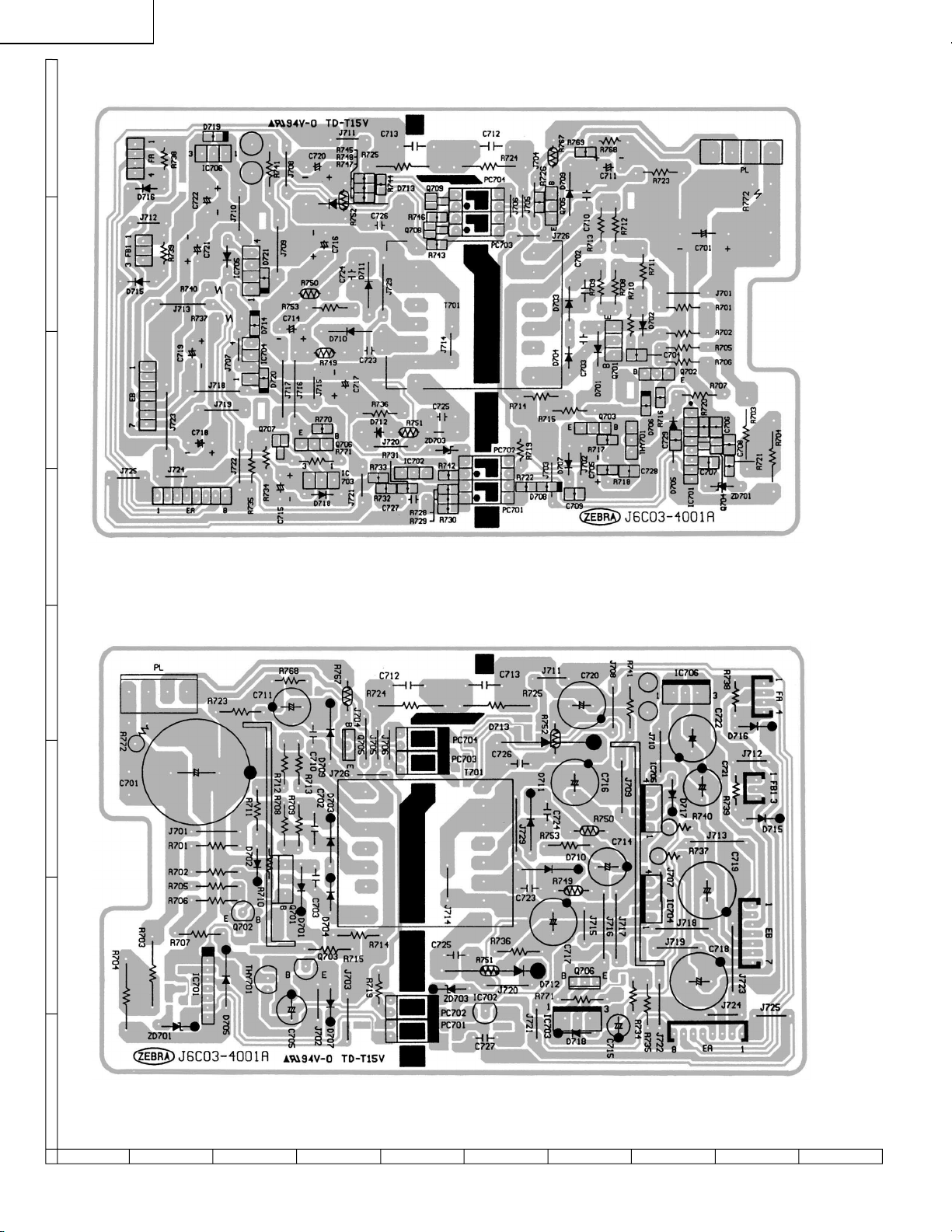
XV-C100U
» Old Unit
H
G
F
E
Power Unit (Wiring Side)
D
C
B
A
Power Unit (Component Side)
87109654321
58
Page 48
Ballast Unit (Wiring Side)
XV-C100U
Ballast Sub Unit (Wiring Side) Ballast Sub Unit (Component Side)
(To CN1703A)
"
Ballast Unit (Wiring Side)
59
1716 1918151413121110
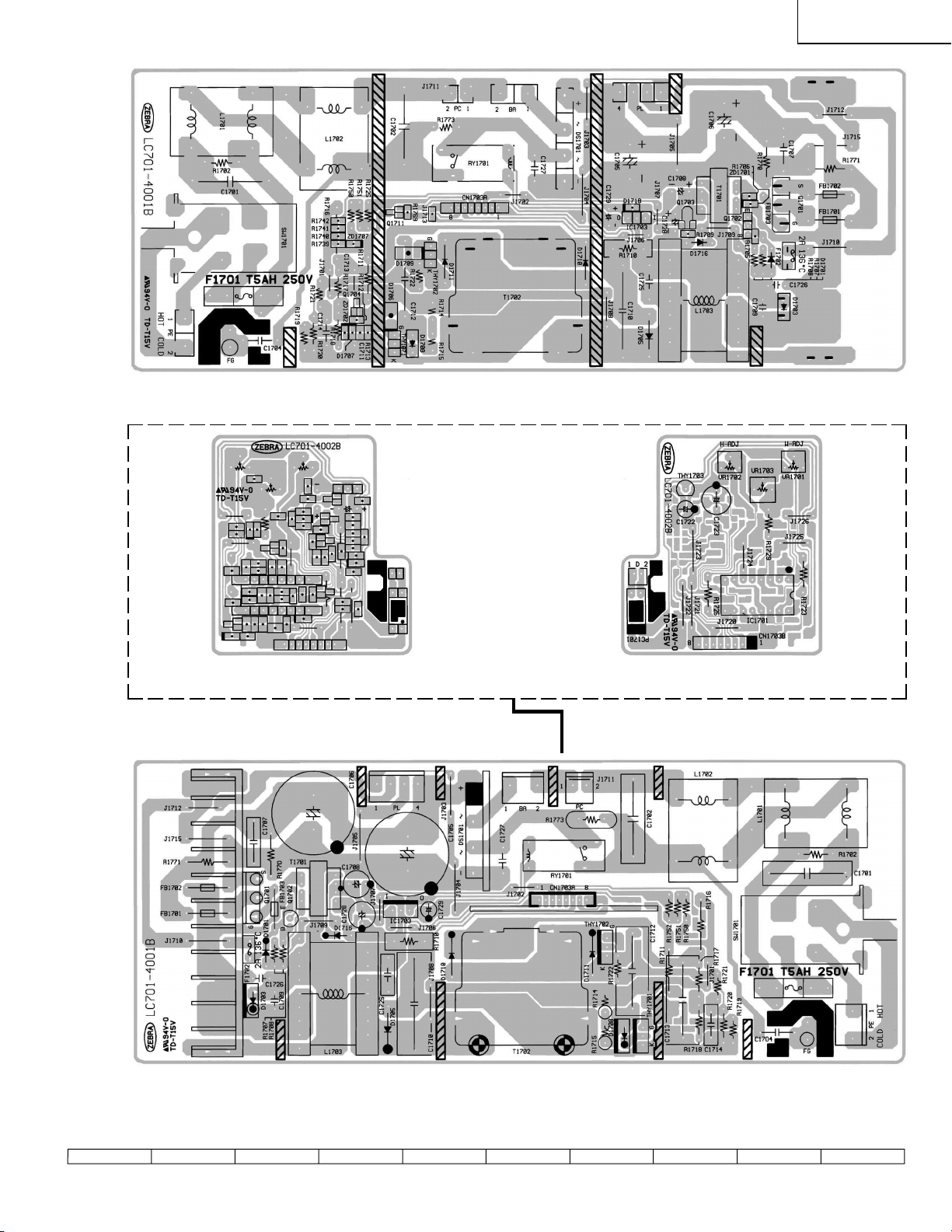
Page 49

XV-C100U
» New Unit
H
G
F
E
Power Unit (Wiring Side)
D
C
B
A
Power Unit (Component Side)
87109654321
60
Page 50

Ballast Unit (Wiring Side)
XV-C100U
Ballast Sub Unit (Wiring Side) Ballast Sub Unit (Component Side)
(To CN1703A)
"
Ballast Unit (Wiring Side)
61
1716 1918151413121110
Page 51

XV-C100U
Ref. No. Part No. ★ Description Code Ref. No. Part No. ★ Description Code
PARTS LIST
PARTS REPLACEMENT
Parts marked with "å" are important for maintaining the safety of
the set. Be sure to replace these parts with specified ones for maintaining the safety and performance of the set.
Les pieces marquées "å" sont importantes pour maintenir la sécurité
de l'appareil. Ne remplacer ces pieces que par des pieces dont le
numéro est spécifié pour maintenir la sécurité et protéger le bon
fonctinnement de l'appareil.
"HOW TO ORDER REPLACEMENT PARTS"
To have your order filled promptly and correctly, please furnish the
following informations.
1. MODEL NUMBER 2. REF. NO.
3. PART NO. 4. DESCRIPTION
5. CODE 6. QUANTITY
in USA: Contact your nearest SHARP Parts Distributor.
For location of SHARP Parts Distributor,
Please call Toll-Free; 1-800-BE-SHARP
in CANADA: Contact SHARP Electronics of Canada Limited
Phone (416) 890-2100.
★ MARK : SPARE PARTS-DELIVERY SECTION
Ref. No. Part No. ★ Description Code
LCD PANEL
NOTE: THE PARTS HERE SHOWN ARE SUPPLIED AS AN
ASSEMBLY BUT NOT INDEPENDENTLY.
RLCDP0088CEZZ J LCD Module Unit CN
PRINTED WIRING BOARD ASSEMBLIES
(NOT REPLACEMENT ITEM)
XV-C100U (for U.S.A.)
DUNTK9001WEV3 – Main Unit —
DUNTK9002WEV3 – Sub Unit —
DUNTK9003WEV3 – Control Unit —
DUNTK9004WEV3 – R/C Reciever Unit —
RUNTK0624CEZZ – Operation Key Unit —
RDENC0271CEZZ – Ballast Unit (1-29 Set) —
DSETU1802FMV3 – Ballast Unit (30-) —
RDENC0272CEZZ – Power Unit (1-29 Set) —
DSETU1796FMV3 – Power Unit (30-) —
XV-C100U (for Canada)
DUNTK9001WEV3 – Main Unit —
DUNTK9002WEV3 – Sub Unit —
DUNTK9003WEV3 – Control Unit —
DUNTK9004WEV3 – R/C Reciever Unit —
RUNTK0624CEZZ – Operation Key Unit —
DSETU1802FMV3 – Ballast Unit —
DSETU1796FMV3 – Power Unit —
IC301 VHiM51132FP-1 J M51132FP AL
IC302 VHiNJ3404AM-1 J NJM3404AM AF
IC303 VHiTDA7052V-1 J TDA7052A AH
IC304 VHiNJM2235M-1 J NJM2235M AE
IC305 VHiNJM2235M-1 J NJM2235M AE
IC306 RH-iX2174CEZZ J MC74HC4538FR AG
IC307 VHiPQ09SZ11-1 J PQ09SZ1U AG
IC401 VHiNJM2283F-1 J NJM2283M AF
IC501 RH-iX2174CEZZ J MC74HC4538FR AG
IC502 RH-iX2174CEZZ J MC74HC4538FR AG
IC503 RH-iX2174CEZZ J MC74HC4538FR AG
IC504 VHiTC7S86F/-1 J TC7S86F AD
IC801 VHiTDA8375A-3 J TDA8375AH/N3 BA
IC802 VHiTDA4665T5E J TDA4665 AN
IC803 VHiTDA8395T-3 J TDA8395T AR
IC804 VHiTDA4565/-1 J TDA4565/V6 AN
IC805 VHiNJM2060M-1 J NJM2060M AE
IC901 VHiPQ20VZ11-1 J PQ20VZ11 AH
IC902 VHiNJ2233BM-1 J NJM2233BM AE
IC904 VHiPQ05TZ11-1 J PQ05TZ11 AH
IC1501 VHiiR3Y12B/-1 J IR3Y12B AU
IC1502 VHiNJM2286M-1 J NJM2286M AE
IC1503 RH-iX2174CEZZ J MC74HC4538FR AG
IC1504 VHiTC7S32F/-1 J TC7S32F AC
IC1505 VHiTC4W53F/-1 J TC4W53F AE
IC3003 VHiCXA1839Q-1 J CXA1839 AZ
Q301 VSRT1N241U/-1 J RT1N241U AB
Q401 VS2SC5384C/-1 J 2SC5384C AB
Q801 VS2PB709AR/-1 J 2PB709AR AB
Q802 VS2PB709AR/-1 J 2PB709AR AB
Q803 VS2PB709AR/-1 J 2PB709AR AB
Q806 VS2PD601AR/-1 J 2PD601AR AB
Q808 VS2PD601AR/-1 J 2PD601AR AB
Q813 VSUPUMZ1///-1 J UPUMZ1 AC
Q814 VS2PD601AR/-1 J 2PD601AR AB
Q815 VS2PD601AR/-1 J 2PD601AR AB
Q816 VS2PD601AR/-1 J 2PD601AR AB
Q819 VS2PD601AR/-1 J 2PD601AR AB
Q820 VS2PB709AR/-1 J 2PB709AR AB
Q821 VSiMX2/////-1 J iMX2 AB
Q822 VSDTC144EK/-1 J DTC144EK AB
Q823 VS2PD601AR/-1 J 2PD601AR AB
Q824 VSUPUMZ1///-1 J UPUMZ1 AC
Q825 VSUPUMT1///-1 J UPUMT1 AC
Q826 VSUPUMZ1///-1 J UPUMZ1 AC
Q827 VSUPUMZ1///-1 J UPUMZ1 AC
Q1501 VS2PB709AR/-1 J 2PB709AR AB
Q1502 VS2PD601AR/-1 J 2PD601AR AB
Q1503 VS2PB709AR/-1 J 2PB709AR AB
Q1504 VS2PD601AR/-1 J 2PD601AR AB
Q1505 VS2PB709AR/-1 J 2PB709AR AB
Q1506 VS2PD601AR/-1 J 2PD601AR AB
Q3001 VS2PD601AR/-1 J 2PD601AR AB
Q3002 VSDTC144EK/-1 J DTC144EK AB
Q3003 VS2PD601AR/-1 J 2PD601AR AB
Q3004 VS2PD601AR/-1 J 2PD601AR AB
Q3005 VS2PD601AR/-1 J 2PD601AR AB
Q3006 VS2PD601AR/-1 J 2PD601AR AB
Q3007 VS2PD601AR/-1 J 2PD601AR AB
Q3010 VS2PD601AR/-1 J 2PD601AR AB
Q3011 VS2PD601AR/-1 J 2PD601AR AB
Q3012 VS2PB709AR/-1 J 2PB709AR AB
Q3013 VS2PD601AR/-1 J 2PD601AR AB
Q3020 VSUPUMZ1///-1 J UPUMZ1 AC
Q3021 VS2SC5384C/-1 J 2SC5384C AB
Q3022 VSDTC144EK/-1 J DTC144EK AB
DUNTK9001WEV3
MAIN UNIT
INTEGRATED CIRCUITS
TRANSISTORS
62
Page 52

XV-C100U
Ref. No. Part No. ★ Description Code Ref. No. Part No. ★ Description Code
DUNTK9001WEV3
MAIN UNIT (Continued)
DIODES
D301 RH-EX0734CEZZ J Zener Diode 12V AD
D302 RH-EX0734CEZZ J Zener Diode 12V AD
D303 VHDDAN202K/-1 J Diode AB
D304 RH-EX0734CEZZ J Zener Diode 12V AD
D305 RH-EX0734CEZZ J Zener Diode 12V AD
D306 RH-EX0734CEZZ J Zener Diode 12V AD
D307 RH-EX0734CEZZ J Zener Diode 12V AD
D308 RH-EX0734CEZZ J Zener Diode 12V AD
D309 RH-EX0734CEZZ J Zener Diode 12V AD
D310 RH-EX0734CEZZ J Zener Diode 12V AD
D311 RH-EX0734CEZZ J Zener Diode 12V AD
D312 VHDDAN202K/-1 J Diode AB
D401 VHDMA153///-1 J Diode AB
D402 RH-EX0734CEZZ J Zener Diode 12V AD
D403 RH-EX0734CEZZ J Zener Diode 12V AD
D405 RH-EX0734CEZZ J Zener Diode 12V AD
D406 RH-EX0734CEZZ J Zener Diode 12V AD
D407 RH-EX0734CEZZ J Zener Diode 12V AD
D408 RH-EX0540CEZZ J Zener Diode 9V AB
D801 VHDMA152WA/-1 J Diode AA
D802 VHDDAN202K/-1 J Diode AB
D903 VHDDAN202K/-1 J Diode AB
D904 VHDDAN202K/-1 J Diode AB
D1501 VHDMA152WA/-1 J Diode AA
PACKAGED CIRCUITS
X801 RCRSB0009PEZZ R Crystal AL
X802 RCRSB0008PEZZ R Crystal AH
COILS
DL401 RCiLZ0964CEZZ J Coil AS
L403 VP-1M270J3R8N J Peaking 27µH AC
L801 VPAWM180J3R6N J Peaking 18µH AD
L802 VP-1M330J4R2N J Peaking 33µH AC
L803 VP-1M120J1R9N J Peaking 12µH AC
L804 VP-1M120J1R9N J Peaking 12µH AC
L1501 VP-1M101J7R7N J Peaking 100µH AC
L1502 RCiLC0055CEZZ J Coil AD
CONTROL
R861 RVR-M4437CEZZ J 68k (B) AGC Adj. AD
CAPACITORS
C301 VCKYTV1CF105Z J 1.0 16V Ceramic AB
C302 VCKYTV1CF105Z J 1.0 16V Ceramic AB
C303 VCEAPF1CW226M J 22 16V Electrolytic AB
C304 VCKYCY1HB103K J 0.01 50V Ceramic AA
C305 VCEAPF1EW475M J 4.7 25V Electrolytic AB
C306 VCKYCY1EF104Z J 0.1 25V Ceramic AA
C307 VCE9PF1CW106M J 10 16V Elect.(N.P) AC
C308 VCE9PF1CW106M J 10 16V Elect.(N.P) AC
C309 VCEAPF1CW106M J 10 16V Electrolytic AB
C310 VCKYTV1CF105Z J 1.0 16V Ceramic AB
C311 VCKYCY1HB103K J 0.01 50V Ceramic AA
C312 RC-EZ0417CEZZ J 150 16V Ceramic AD
C313 VCKYCY1EF104Z J 0.1 25V Ceramic AA
C314 VCEAPK1CN107M J 100 16V Electrolytic AD
C315 VCEAPF1CW106M J 10 16V Electrolytic AB
C316 VCKYCY1HB103K J 0.01 50V Ceramic AA
C317 VCKYCY1CF104Z J 0.1 16V Ceramic AA
C318 VCEAPF1CW106M J 10 16V Electrolytic AB
C319 VCEAPF1CW106M J 10 16V Electrolytic AB
C320 VCKYCY1HB103K J 0.01 50V Ceramic AA
C321 VCCCCY1HH561J J 560p 50V Ceramic AB
C322 VCCCCY1HH561J J 560p 50V Ceramic AB
C323 VCEAPF1CW107M J 100 16V Electrolytic AD
C324 VCKYCY1HB102K J 1000p 50V Ceramic AA
C325 VCKYCY1CF104Z J 0.1 16V Ceramic AA
C326 VCEAPF1CW106M J 10 16V Electrolytic AB
C330 VCKYCY1EF104Z J 0.1 25V Ceramic AA
C331 VCKYCY1HB222K J 2200p 50V Ceramic AA
C332 VCKYCY1HB222K J 2200p 50V Ceramic AA
C333 VCEAPF0JW226M J 22 6.3V Electrolytic AB
C401 VCEAPH1CW106M J 10 16V Electrolytic AB
C402 VCKYCY1HB103K J 0.01 50V Ceramic AA
C403 VCEAPF1CW106M J 10 16V Electrolytic AB
C404 VCCCCY1HH101J J 100p 50V Ceramic AA
C405 VCEAPF1CW106M J 10 16V Electrolytic AB
C406 VCEAPF1CW226M J 22 16V Electrolytic AB
C408 VCKYCY1EF104Z J 0.1 25V Ceramic AA
C409 VCEAPF1CW107M J 100 16V Electrolytic AD
C410 VCCCCY1HH101J J 100p 50V Ceramic AA
C411 VCE9PF1CW106M J 10 16V Elect.(N.P) AC
C412 VCEAPF1CW106M J 10 16V Electrolytic AB
C415 VCKYCY1HB103K J 0.01 50V Ceramic AA
C418 VCKYCY1HB103K J 0.01 50V Ceramic AA
C420 VCEAPF1CW476M J 47 16V Electrolytic AC
C422 VCCCCY1HH330J J 33p 50V Ceramic AA
C423 VCCCCY1HH390J J 39p 50V Ceramic AA
C501 VCCCCY1EH102J J 1000p 25V Ceramic AB
C502 VCCCCY1EH102J J 1000p 25V Ceramic AB
C503 VCKYCY1EF104Z J 0.1 25V Ceramic AA
C504 VCCCCY1HH271J J 270p 50V Ceramic AA
C505 VCFYEC1CM104J J 0.1 16V M.Polyester AD
C506 VCKYCY1EF104Z J 0.1 25V Ceramic AA
C507 VCCCCY1EH102J J 1000p 25V Ceramic AB
C508 VCCCCY1EH821J J 820p 25V Ceramic AB
C509 VCKYCY1EF104Z J 0.1 25V Ceramic AA
C510 VCEAPF1HW105M J 1.0 50V Electrolytic AB
C511 VCKYCY1EF104Z J 0.1 25V Ceramic AA
C801 VCCCCY1HH470J J 47p 50V Ceramic AA
C802 VCCCCY1HH330J J 33p 50V Ceramic AA
C803 VCKYCY1HB103K J 0.01 50V Ceramic AA
C804 VCEAPF1CW476M J 47 16V Electrolytic AC
C805 VCKYCY1EF104Z J 0.1 25V Ceramic AA
C806 VCKYCY1EF104Z J 0.1 25V Ceramic AA
C807 VCKYTV1HF224Z J 0.22 50V Ceramic AC
C808 VCKYCY1HB102K J 1000p 50V Ceramic AA
C809 VCKYCY1HB102K J 1000p 50V Ceramic AA
C810 VCCCCY1HH180J J 18p 50V Ceramic AA
C811 VCCCCY1HH180J J 18p 50V Ceramic AA
C812 VCKYCY1HB103K J 0.01 50V Ceramic AA
C813 VCEAPF1CW106M J 10 16V Electrolytic AB
C814 VCKYCY1EF104Z J 0.1 25V Ceramic AA
C815 VCKYCY1EF104Z J 0.1 25V Ceramic AA
C816 VCKYCY1EF104Z J 0.1 25V Ceramic AA
C817 VCKYCY1EF104Z J 0.1 25V Ceramic AA
C818 VCFYEC1CM334J J 0.33 16V M.Polyester AE
C819 VCCCCY1HH221J J 220p 50V Ceramic AA
C820 VCCCCY1HH221J J 220p 50V Ceramic AA
C821 VCFYEC1CM334J J 0.33 16V M.Polyester AE
C822 VCCCCY1HH470J J 47p 50V Ceramic AA
C823 VCCCCY1HH470J J 47p 50V Ceramic AA
C824 VCCCCY1HH221J J 220p 50V Ceramic AA
C825 VCCCCY1HH221J J 220p 50V Ceramic AA
C826 VCKYCY1EF104Z J 0.1 25V Ceramic AA
C827 VCE9PF1CW475M J 4.7 16V Elect.(N.P) AC
C828 VCE9PF1HW105M J 1.0 50V Elect.(N.P) AC
C829 VCEAPF1CW106M J 10 16V Electrolytic AB
C830 VCKYCY1EF104Z J 0.1 25V Ceramic AA
C831 VCKYCY1EF104Z J 0.1 25V Ceramic AA
C832 VCKYCY1EF104Z J 0.1 25V Ceramic AA
C833 VCKYCY1EF104Z J 0.1 25V Ceramic AA
C834 VCFRED1HM472J J 4700p 50V M.Polyester AD
C835 VCEAPF1CW107M J 100 16V Electrolytic AD
C836 VCKYTV1HF224Z J 0.22 50V Ceramic AC
C837 VCEAPF1CW107M J 100 16V Electrolytic AD
C838 VCKYTV1HF224Z J 0.22 50V Ceramic AC
C839 VCEAPF1HW225M J 2.2 50V Electrolytic AB
C840 VCFYEC1CM223J J 0.022 16V M.Polyester AC
C841 VCCCCY1HH221J J 220p 50V Ceramic AA
C842 VCKYCY1EF104Z J 0.1 25V Ceramic AA
C843 VCKYCY1HB103K J 0.01 50V Ceramic AA
C844 VCCCCY1HH221J J 220p 50V Ceramic AA
C845 VCEAPF1HW225M J 2.2 50V Electrolytic AB
C848 VCKYCY1HB103K J 0.01 50V Ceramic AA
63
Page 53

XV-C100U
Ref. No. Part No. ★ Description Code Ref. No. Part No. ★ Description Code
DUNTK9001WEV3
MAIN UNIT (Continued)
C849 VCEAPF1HW105M J 1.0 50V Electrolytic AB
C850 VCEAPF1CW476M J 47 16V Electrolytic AC
C852 VCCCCY1HH820J J 82p 50V Ceramic AA
C853 VCCCCY1HH270J J 27p 50V Ceramic AA
C860 VCCCCY1HH221J J 220p 50V Ceramic AA
C861 VCE9PF1CW106M J 10 16V Elect.(N.P) AC
C864 VCE9PF1CW475M J 4.7 16V Elect.(N.P) AC
C865 VCKYCY1EF104Z J 0.1 25V Ceramic AA
C867 VCKYCY1EF104Z J 0.1 25V Ceramic AA
C868 VCKYCY1HB103K J 0.01 50V Ceramic AA
C869 VCKYCY1EF104Z J 0.1 25V Ceramic AA
C870 VCCCCY1HH101J J 100p 50V Ceramic AA
C871 VCKYCY1HB103K J 0.01 50V Ceramic AA
C872 VCEAPF1HW106M J 10 50V Electrolytic AB
C873 VCCCCY1HH330J J 33p 50V Ceramic AA
C874 VCKYCY1HB103K J 0.01 50V Ceramic AA
C875 VCCCCY1HH820J J 82p 50V Ceramic AA
C876 VCCCCY1HH270J J 27p 50V Ceramic AA
C877 VCKYCY1EF104Z J 0.1 25V Ceramic AA
C878 VCKYCY1HB103K J 0.01 50V Ceramic AA
C879 VCCCCY1HH330J J 33p 50V Ceramic AA
C880 VCCCCY1HH330J J 33p 50V Ceramic AA
C881 VCFYFA1HA274J J 0.27 50V M.Polyester AD
C882 VCEAPF1HW105M J 1.0 50V Electrolytic AB
C883 VCKYCY1HB103K J 0.01 50V Ceramic AA
C884 VCKYCY1HB103K J 0.01 50V Ceramic AA
C885 VCKYCY1HB103K J 0.01 50V Ceramic AA
C886 VCKYCY1HB103K J 0.01 50V Ceramic AA
C887 VCKYCY1HB103K J 0.01 50V Ceramic AA
C888 VCFRED1HM222J J 2200p 50V M.Polyester AC
C889 VCFYEC1CM102J J 1000p 16V M.Polyester AC
C890 VCFYFA1HA274J J 0.27 50V M.Polyester AD
C891 VCEAPF1CW476M J 47 16V Electrolytic AC
C893 VCEAPF1HW225M J 2.2 50V Electrolytic AB
C901 VCEAPF1CW107M J 100 16V Electrolytic AD
C902 VCEAPF0JW107M J 100 6.3V Electrolytic AC
C903 VCKYCY1EF104Z J 0.1 25V Ceramic AA
C904 VCEAPF1CW106M J 10 16V Electrolytic AB
C905 VCKYCY1EF104Z J 0.1 25V Ceramic AA
C906 VCE9PF1CW106M J 10 16V Elect.(N.P) AC
C907 VCEAPF1CW476M J 47 16V Electrolytic AC
C922 VCKYCY1EF104Z J 0.1 25V Ceramic AA
C1501 VCEAPF1CW107M J 100 16V Electrolytic AD
C1502 VCKYCY1EF104Z J 0.1 25V Ceramic AA
C1504 VCKYCY1CF104Z J 0.1 16V Ceramic AA
C1505 VCKYCY1HB103K J 0.01 50V Ceramic AA
C1506 VCKYCY1HB103K J 0.01 50V Ceramic AA
C1507 VCKYCY1HB103K J 0.01 50V Ceramic AA
C1508 VCKYCY1HB103K J 0.01 50V Ceramic AA
C1509 VCKYCY1HB103K J 0.01 50V Ceramic AA
C1510 VCKYCY1HB103K J 0.01 50V Ceramic AA
C1511 VCKYCY1HB103K J 0.01 50V Ceramic AA
C1512 VCKYCY1AF105Z J 1.0 10V Ceramic AC
C1513 VCKYCY1AF105Z J 1.0 10V Ceramic AC
C1514 VCKYCY1AF105Z J 1.0 10V Ceramic AC
C1515 VCKYTV1CF105Z J 1.0 16V Ceramic AB
C1516 RC-EZ0363CEZZ J 330 6.3V Electrolitic AC
C1517 VCEAPF1CW106M J 10 16V Electrolytic AB
C1518 VCKYTV1CF105Z J 1.0 16V Ceramic AB
C1519 VCKYCY1HB222K J 2200p 50V Ceramic AA
C1520 VCKYCY1HB153K J 0.015 50V Ceramic AA
C1521 VCKYTV1CF105Z J 1.0 16V Ceramic AB
C1522 VCCCCY1HH151J J 150p 50V Ceramic AA
C1523 VCKYCY1HB103K J 0.01 50V Ceramic AA
C1524 VCKYCY1EF104Z J 0.1 25V Ceramic AA
C1525 VCCCCY1EH821J J 820p 25V Ceramic AB
C1526 VCCCCY1EH102J J 1000p 25V Ceramic AB
C1527 VCKYCY1AF105Z J 1.0 10V Ceramic AC
C1528 VCKYCY1AF105Z J 1.0 10V Ceramic AC
C1529 VCKYCY1AF105Z J 1.0 10V Ceramic AC
C1530 VCKYCY1HB103K J 0.01 50V Ceramic AA
C1531 VCEAPF1CW226M J 22 16V Electrolytic AB
C1535 VCKYCY1CF104Z J 0.1 16V Ceramic AA
C3001 VCKYCY1AF105Z J 1.0 10V Ceramic AC
C3002 VCKYCY1AF105Z J 1.0 10V Ceramic AC
C3008 VCEAPF1CW106M J 10 16V Electrolytic AB
C3009 VCKYCY1HB103K J 0.01 50V Ceramic AA
C3010 VCKYCY1HB103K J 0.01 50V Ceramic AA
C3011 VCKYCY1HB103K J 0.01 50V Ceramic AA
C3012 VCE9PF1HW225M J 2.2 50V Elect.(N.P) AC
C3013 VCKYCY1CF104Z J 0.1 16V Ceramic AA
C3014 VCKYCY1CF104Z J 0.1 16V Ceramic AA
C3015 VCEAPF1HW474M J 0.47 50V Electrolytic AB
C3016 VCEAPF1CW106M J 10 16V Electrolytic AB
C3017 VCKYCY1HB103K J 0.01 50V Ceramic AA
C3018 VCKYCY1HB103K J 0.01 50V Ceramic AA
C3019 VCKYCY1HB103K J 0.01 50V Ceramic AA
C3020 VCKYCY1HB103K J 0.01 50V Ceramic AA
C3021 VCKYCY1HB103K J 0.01 50V Ceramic AA
C3022 VCKYCY1HB103K J 0.01 50V Ceramic AA
C3024 VCEAPF1CW106M J 10 16V Electrolytic AB
C3028 VCKYCY1CF104Z J 0.1 16V Ceramic AA
C3030 VCEAPF1CW106M J 10 16V Electrolytic AB
C3031 VCE9PF1CW106M J 10 16V Elect.(N.P) AC
C3032 VCCCCY1HH100D J 10p 50V Ceramic AA
C3033 VCCCCY1HH271J J 270p 50V Ceramic AA
RESISTORS
R301 VRS-CY1JF105J J 1M 1/16W Metal Oxide AA
R303 VRS-CY1JF105J J 1M 1/16W Metal Oxide AA
R305 VRS-CY1JF103J J 10k 1/16W Metal Oxide AA
R306 VRS-CY1JF473J J 47k 1/16W Metal Oxide AA
R307 VRS-CY1JF101J J 100 1/16W Metal Oxide AA
R308 VRS-CY1JF103J J 10k 1/16W Metal Oxide AA
R309 VRS-CY1JF473J J 47k 1/16W Metal Oxide AA
R310 VRS-CY1JF101J J 100 1/16W Metal Oxide AA
R311 VRS-CY1JF102J J 1.0k 1/16W Metal Oxide AA
R312 VRS-CY1JF103J J 10k 1/16W Metal Oxide AA
R313 VRS-CY1JF103J J 10k 1/16W Metal Oxide AA
R314 VRS-CY1JF152J J 1.5k 1/16W Metal Oxide AA
R315 VRS-CY1JF682J J 6.8k 1/16W Metal Oxide AA
R316 VRS-CY1JF152J J 1.5k 1/16W Metal Oxide AA
R317 VRS-CY1JF682J J 6.8k 1/16W Metal Oxide AA
R318 VRS-CY1JF153J J 15k 1/16W Metal Oxide AA
R319 VRS-CY1JF103J J 10k 1/16W Metal Oxide AA
R320 VRS-TW2ED151J J 150 1/4W Metal Oxide AA
R321 VRS-TW2ED151J J 150 1/4W Metal Oxide AA
R322 VRS-CY1JF105J J 1M 1/16W Metal Oxide AA
R323 VRS-CY1JF103J J 10k 1/16W Metal Oxide AA
R324 VRS-CY1JF223J J 22k 1/16W Metal Oxide AA
R325 VRS-CY1JF103J J 10k 1/16W Metal Oxide AA
R326 VRS-CY1JF105J J 1M 1/16W Metal Oxide AA
R327 VRS-CY1JF102J J 1.0k 1/16W Metal Oxide AA
R328 VRS-CY1JF100J J 10 1/16W Metal Oxide AA
R329 VRS-CY1JF102J J 1.0k 1/16W Metal Oxide AA
R330 VRS-CY1JF000J J 0 1/16W Metal Oxide AA
R331 VRS-CY1JF102J J 1.0k 1/16W Metal Oxide AA
R332 VRS-CY1JF101J J 100 1/16W Metal Oxide AA
R335 VRS-CY1JF102J J 1.0k 1/16W Metal Oxide AA
R336 VRS-CY1JF101J J 100 1/16W Metal Oxide AA
R337 VRN-CY1JF103D J 10k 1/16W Metal Film AA
R338 VRS-CY1JF104J J 100k 1/16W Metal Oxide AA
R339 VRS-CY1JF152J J 1.5k 1/16W Metal Oxide AA
R340 VRS-CY1JF101J J 100 1/16W Metal Oxide AA
R341 VRN-CY1JF392D J 3.9k 1/16W Metal Film AA
R342 VRS-CY1JF472J J 4.7k 1/16W Metal Oxide AA
R343 VRS-VV3DB180J J 18 2W Metal Oxide AA
R344 VRS-VV3DB180J J 18 2W Metal Oxide AA
R360 VRS-CY1JF122J J 1.2k 1/16W Metal Oxide AA
R361 VRS-CY1JF472J J 4.7k 1/16W Metal Oxide AA
R363 VRS-TW2ED221J J 220 1/4W Metal Oxide AA
R364 VRS-TW2ED221J J 220 1/4W Metal Oxide AA
R366 VRS-TV1JD000J J 0 1/16W Metal Oxide AA
R397 VRS-CA1JF000J J 0 1/16W Metal Oxide AB
R401 VRS-TW2ED750J J 75 1/4W Metal Oxide AA
R402 VRS-CY1JF101J J 100 1/16W Metal Oxide AA
R403 VRS-CY1JF102J J 1.0k 1/16W Metal Oxide AA
R404 VRS-CY1JF1R0J J 1.0 1/16W Metal Oxide AA
64
Page 54

XV-C100U
Ref. No. Part No. ★ Description Code Ref. No. Part No. ★ Description Code
DUNTK9001WEV3
MAIN UNIT (Continued)
R405 VRS-TW2ED750J J 75 1/4W Metal Oxide AA
R406 VRS-CY1JF100J J 10 1/16W Metal Oxide AA
R407 VRS-TW2ED750J J 75 1/4W Metal Oxide AA
R408 VRS-CY1JF101J J 100 1/16W Metal Oxide AA
R409 VRS-CY1JF273J J 27k 1/16W Metal Oxide AA
R410 VRS-CY1JF123J J 12k 1/16W Metal Oxide AA
R411 VRS-CY1JF471J J 470 1/16W Metal Oxide AA
R412 VRS-CY1JF101J J 100 1/16W Metal Oxide AA
R413 VRS-CY1JF101J J 100 1/16W Metal Oxide AA
R414 VRS-CY1JF101J J 100 1/16W Metal Oxide AA
R415 VRS-CY1JF100J J 10 1/16W Metal Oxide AA
R416 VRS-CY1JF101J J 100 1/16W Metal Oxide AA
R417 VRS-TX2HF680J J 68 1/2W Metal Oxide AA
R419 VRS-CY1JF100J J 10 1/16W Metal Oxide AA
R420 VRS-TV1JD000J J 0 1/16W Metal Oxide AA
R421 VRS-CY1JF000J J 0 1/16W Metal Oxide AA
R430 VRS-TV1JD000J J 0 1/16W Metal Oxide AA
R431 VRS-CY1JF472J J 4.7k 1/16W Metal Oxide AA
R501 VRN-CY1JF752D J 7.5k 1/16W Metal Film AA
R502 VRN-CY1JF153D J 15k 1/16W Metal Film AA
R504 VRN-CY1JF272D J 2.7k 1/16W Metal Film AB
R505 VRN-CY1JF273D J 27k 1/16W Metal Film AB
R506 VRN-CY1JF103D J 10k 1/16W Metal Film AA
R507 VRN-CY1JF682D J 6.8k 1/16W Metal Film AB
R508 VRS-CY1JF152J J 1.5k 1/16W Metal Oxide AA
R509 VRS-CY1JF101J J 100 1/16W Metal Oxide AA
R515 VRS-CY1JF273J J 27k 1/16W Metal Oxide AA
R516 VRS-CY1JF103J J 10k 1/16W Metal Oxide AA
R517 VRS-CY1JF103J J 10k 1/16W Metal Oxide AA
R518 VRS-CY1JF103J J 10k 1/16W Metal Oxide AA
R519 VRS-CY1JF123J J 12k 1/16W Metal Oxide AA
R521 VRS-CY1JF102J J 1.0k 1/16W Metal Oxide AA
R801 VRS-CY1JF331J J 330 1/16W Metal Oxide AA
R802 VRS-TX2HF100J J 10 1/2W Metal Oxide AA
R803 VRS-CY1JF103J J 10k 1/16W Metal Oxide AA
R804 VRS-TX2HF270J J 27 1/2W Metal Oxide AB
R805 VRS-CY1JF102J J 1.0k 1/16W Metal Oxide AA
R806 VRS-CY1JF102J J 1.0k 1/16W Metal Oxide AA
R807 VRS-CY1JF101J J 100 1/16W Metal Oxide AA
R809 VRS-CY1JF103J J 10k 1/16W Metal Oxide AA
R810 VRS-CY1JF000J J 0 1/16W Metal Oxide AA
R811 VRS-CY1JF681J J 680 1/16W Metal Oxide AA
R812 VRS-CY1JF183J J 18k 1/16W Metal Oxide AA
R813 VRS-CY1JF105J J 1M 1/16W Metal Oxide AA
R814 VRS-CY1JF101J J 100 1/16W Metal Oxide AA
R815 VRS-TX2HF5R6J J 5.6 1/2W Metal Oxide AA
R816 VRS-CY1JF104J J 100k 1/16W Metal Oxide AA
R817 VRS-TX2HF4R7J J 4.7 1/2W Metal Oxide AB
R818 VRS-CY1JF334J J 330k 1/16W Metal Oxide AA
R819 VRS-CY1JF101J J 100 1/16W Metal Oxide AA
R820 VRS-CY1JF103J J 10k 1/16W Metal Oxide AA
R821 VRS-CY1JF473J J 47k 1/16W Metal Oxide AA
R824 VRS-CY1JF102J J 1.0k 1/16W Metal Oxide AA
R827 VRS-CY1JF102J J 1.0k 1/16W Metal Oxide AA
R830 VRS-CY1JF102J J 1.0k 1/16W Metal Oxide AA
R831 VRS-CY1JF103J J 10k 1/16W Metal Oxide AA
R832 VRS-TX2HF4R7J J 4.7 1/2W Metal Oxide AB
R833 VRS-CY1JF391J J 390 1/16W Metal Oxide AA
R834 VRS-CY1JF333J J 33k 1/16W Metal Oxide AA
R835 VRS-CY1JF393J J 39k 1/16W Metal Oxide AA
R836 VRS-CY1JF102J J 1.0k 1/16W Metal Oxide AA
R837 VRS-CY1JF564J J 560k 1/16W Metal Oxide AA
R838 VRS-CY1JF333J J 33k 1/16W Metal Oxide AA
R839 VRS-CY1JF104J J 100k 1/16W Metal Oxide AA
R840 VRS-CY1JF472J J 4.7k 1/16W Metal Oxide AA
R841 VRS-CY1JF182J J 1.8k 1/16W Metal Oxide AA
R842 VRN-CY1JF153D J 15k 1/16W Metal Film AA
R845 VRS-CY1JF102J J 1.0k 1/16W Metal Oxide AA
R846 VRS-CY1JF102J J 1.0k 1/16W Metal Oxide AA
R847 VRS-CY1JF102J J 1.0k 1/16W Metal Oxide AA
R848 VRS-CY1JF102J J 1.0k 1/16W Metal Oxide AA
R849 VRS-CY1JF472J J 4.7k 1/16W Metal Oxide AA
R850 VRS-CY1JF103J J 10k 1/16W Metal Oxide AA
R851 VRN-CY1JF391D J 390 1/16W Metal Film AB
R852 VRS-CY1JF102J J 1.0k 1/16W Metal Oxide AA
R853 VRS-CY1JF103J J 10k 1/16W Metal Oxide AA
R854 VRS-CY1JF101J J 100 1/16W Metal Oxide AA
R855 VRS-CY1JF221J J 220 1/16W Metal Oxide AA
R856 VRS-CY1JF101J J 100 1/16W Metal Oxide AA
R857 VRS-CY1JF271J J 270 1/16W Metal Oxide AA
R858 VRS-CY1JF222J J 2.2k 1/16W Metal Oxide AA
R859 VRS-CY1JF103J J 10k 1/16W Metal Oxide AA
R860 VRS-CY1JF562J J 5.6k 1/16W Metal Oxide AA
R862 VRS-CY1JF102J J 1.0k 1/16W Metal Oxide AA
R863 VRS-CY1JF183J J 18k 1/16W Metal Oxide AA
R864 VRS-CY1JF272J J 2.7k 1/16W Metal Oxide AA
R865 VRS-CY1JF102J J 1.0k 1/16W Metal Oxide AA
R866 VRS-CY1JF103J J 10k 1/16W Metal Oxide AA
R867 VRS-CY1JF223J J 22k 1/16W Metal Oxide AA
R868 VRS-CY1JF223J J 22k 1/16W Metal Oxide AA
R869 VRS-CY1JF123J J 12k 1/16W Metal Oxide AA
R870 VRS-CY1JF272J J 2.7k 1/16W Metal Oxide AA
R871 VRS-CY1JF103J J 10k 1/16W Metal Oxide AA
R872 VRS-CY1JF103J J 10k 1/16W Metal Oxide AA
R873 VRS-CY1JF152J J 1.5k 1/16W Metal Oxide AA
R874 VRS-CY1JF683J J 68k 1/16W Metal Oxide AA
R875 VRS-CY1JF224J J 220k 1/16W Metal Oxide AA
R876 VRS-CY1JF101J J 100 1/16W Metal Oxide AA
R877 VRS-CY1JF472J J 4.7k 1/16W Metal Oxide AA
R878 VRS-CY1JF682J J 6.8k 1/16W Metal Oxide AA
R879 VRS-CY1JF332J J 3.3k 1/16W Metal Oxide AA
R880 VRS-CY1JF102J J 1.0k 1/16W Metal Oxide AA
R881 VRS-CY1JF152J J 1.5k 1/16W Metal Oxide AA
R882 VRN-CY1JF332D J 3.3k 1/16W Metal Film AA
R883 VRN-CY1JF152D J 1.5k 1/16W Metal Film AB
R884 VRS-CY1JF105J J 1M 1/16W Metal Oxide AA
R885 VRS-CY1JF101J J 100 1/16W Metal Oxide AA
R886 VRS-CY1JF105J J 1M 1/16W Metal Oxide AA
R887 VRS-CY1JF222J J 2.2k 1/16W Metal Oxide AA
R888 VRS-CY1JF472J J 4.7k 1/16W Metal Oxide AA
R889 VRS-CY1JF222J J 2.2k 1/16W Metal Oxide AA
R890 VRS-CY1JF821J J 820 1/16W Metal Oxide AA
R891 VRS-CY1JF122J J 1.2k 1/16W Metal Oxide AA
R892 VRS-CY1JF273J J 27k 1/16W Metal Oxide AA
R893 VRS-CY1JF151J J 150 1/16W Metal Oxide AA
R894 VRS-CY1JF103J J 10k 1/16W Metal Oxide AA
R895 VRS-CY1JF102J J 1.0k 1/16W Metal Oxide AA
R896 VRS-CY1JF000J J 0 1/16W Metal Oxide AA
R897 VRS-CY1JF152J J 1.5k 1/16W Metal Oxide AA
R898 VRS-CY1JF271J J 270 1/16W Metal Oxide AA
R899 VRS-CY1JF152J J 1.5k 1/16W Metal Oxide AA
R900 VRS-CY1JF472J J 4.7k 1/16W Metal Oxide AA
R901 VRS-CY1JF102J J 1.0k 1/16W Metal Oxide AA
R902 VRS-CY1JF101J J 100 1/16W Metal Oxide AA
R903 VRS-CY1JF101J J 100 1/16W Metal Oxide AA
R904 VRS-CY1JF101J J 100 1/16W Metal Oxide AA
R906 VRS-CY1JF103J J 10k 1/16W Metal Oxide AA
R907 VRS-CY1JF103J J 10k 1/16W Metal Oxide AA
R908 VRS-CY1JF103J J 10k 1/16W Metal Oxide AA
R909 VRS-CY1JF102J J 1.0k 1/16W Metal Oxide AA
R910 VRS-CY1JF473J J 47k 1/16W Metal Oxide AA
R911 VRS-CY1JF332J J 3.3k 1/16W Metal Oxide AA
R912 VRS-CY1JF222J J 2.2k 1/16W Metal Oxide AA
R913 VRS-CY1JF273J J 27k 1/16W Metal Oxide AA
R914 VRS-CY1JF103J J 10k 1/16W Metal Oxide AA
R915 VRS-CY1JF103J J 10k 1/16W Metal Oxide AA
R916 VRS-CY1JF472J J 4.7k 1/16W Metal Oxide AA
R917 VRS-CY1JF152J J 1.5k 1/16W Metal Oxide AA
R918 VRS-CY1JF102J J 1.0k 1/16W Metal Oxide AA
R919 VRS-TX2HF8R2J J 8.2 1/2W Metal Oxide AA
R920 VRS-TX2HF100J J 1 0 1/2W Metal Oxide AA
R921 VRS-CY1JF103J J 10k 1/16W Metal Oxide AA
R923 VRS-CY1JF103J J 10k 1/16W Metal Oxide AA
R924 VRS-CY1JF122J J 1.2k 1/16W Metal Oxide AA
R925 VRS-CY1JF121J J 120 1/16W Metal Oxide AA
R929 VRS-CY1JF101J J 100 1/16W Metal Oxide AA
R930 VRS-CY1JF101J J 100 1/16W Metal Oxide AA
R932 VRS-CY1JF000J J 0 1/16W Metal Oxide AA
65
Page 55

XV-C100U
Ref. No. Part No. ★ Description Code Ref. No. Part No. ★ Description Code
DUNTK9001WEV3
MAIN UNIT (Continued)
R933 VRS-CY1JF122J J 1.2k 1/16W Metal Oxide AA
R935 VRS-CY1JF101J J 100 1/16W Metal Oxide AA
R936 VRS-CY1JF103J J 10k 1/16W Metal Oxide AA
R937 VRS-CA1JF101J J 100 1/16W Metal Oxide AA
R938 VRS-CB1JF152J J 1.5k 1/16W Metal Oxide AC
R939 VRS-CB1JF681J J 680 1/16W Metal Oxide AC
R940 VRS-CY1JF000J J 0 1/16W Metal Oxide AA
R1501 VRS-CY1JF102J J 1.0k 1/16W Metal Oxide AA
R1502 VRS-CY1JF102J J 1.0k 1/16W Metal Oxide AA
R1503 VRS-CY1JF102J J 1.0k 1/16W Metal Oxide AA
R1504 VRS-CY1JF221J J 220 1/16W Metal Oxide AA
R1505 VRS-CY1JF333J J 33k 1/16W Metal Oxide AA
R1506 VRS-CY1JF273J J 27k 1/16W Metal Oxide AA
R1508 VRS-CY1JF124J J 120k 1/16W Metal Oxide AA
R1509 VRS-CY1JF124J J 120k 1/16W Metal Oxide AA
R1511 VRS-CY1JF153J J 15k 1/16W Metal Oxide AA
R1512 VRS-CY1JF823J J 82k 1/16W Metal Oxide AA
R1513 VRS-CY1JF103J J 10k 1/16W Metal Oxide AA
R1514 VRS-CY1JF472J J 4.7k 1/16W Metal Oxide AA
R1515 VRS-CY1JF473J J 47k 1/16W Metal Oxide AA
R1516 VRS-CY1JF273J J 27k 1/16W Metal Oxide AA
R1517 VRS-CY1JF473J J 47k 1/16W Metal Oxide AA
R1518 VRS-CY1JF393J J 39k 1/16W Metal Oxide AA
R1519 VRS-CY1JF563J J 56k 1/16W Metal Oxide AA
R1520 VRS-CY1JF243F J 24k 1/16W Metal Oxide AA
R1521 VRS-CY1JF243F J 24k 1/16W Metal Oxide AA
R1522 VRS-CY1JF473J J 47k 1/16W Metal Oxide AA
R1523 VRS-CY1JF563J J 56k 1/16W Metal Oxide AA
R1524 VRS-CY1JF473J J 47k 1/16W Metal Oxide AA
R1525 VRS-CY1JF683J J 68k 1/16W Metal Oxide AA
R1526 VRS-CY1JF563J J 56k 1/16W Metal Oxide AA
R1527 VRS-CY1JF683J J 68k 1/16W Metal Oxide AA
R1528 VRS-CY1JF473J J 47k 1/16W Metal Oxide AA
R1529 VRS-CY1JF563J J 56k 1/16W Metal Oxide AA
R1530 VRS-CY1JF105J J 1M 1/16W Metal Oxide AA
R1531 VRS-CY1JF105J J 1M 1/16W Metal Oxide AA
R1532 VRS-CY1JF271J J 270 1/16W Metal Oxide AA
R1533 VRS-CY1JF102J J 1.0k 1/16W Metal Oxide AA
R1534 VRS-CY1JF272F J 2.7k 1/16W Metal Oxide AA
R1535 VRS-CY1JF333J J 33k 1/16W Metal Oxide AA
R1538 VRS-CY1JF473J J 47k 1/16W Metal Oxide AA
R1539 VRS-CY1JF333J J 33k 1/16W Metal Oxide AA
R1540 VRS-CY1JF124J J 120k 1/16W Metal Oxide AA
R1541 VRS-CY1JF473J J 47k 1/16W Metal Oxide AA
R1542 VRS-CY1JF473J J 47k 1/16W Metal Oxide AA
R1543 VRS-CY1JF104J J 100k 1/16W Metal Oxide AA
R1544 VRN-CY1JF272D J 2.7k 1/16W Metal Film AB
R1546 VRN-CY1JF123D J 12k 1/16W Metal Film AB
R1547 VRS-CY1JF185J J 1.8M 1/16WMetal Oxide AE
R1548 VRS-CY1JF185J J 1.8M 1/16WMetal Oxide AE
R1549 VRS-CY1JF185J J 1.8M 1/16WMetal Oxide AE
R1551 VRS-CY1JF470J J 47 1/16W Metal Oxide AA
R1552 VRS-TV1JD5R6J J 5.6 1/16W Metal Oxide AA
R1553 VRS-TX2HF681J J 680 1/2W Metal Oxide AA
R1554 VRS-TX2HF681J J 680 1/2W Metal Oxide AA
R1555 VRS-CY1JF470J J 47 1/16W Metal Oxide AA
R1556 VRS-TV1JD5R6J J 5.6 1/16W Metal Oxide AA
R1557 VRS-TX2HF681J J 680 1/2W Metal Oxide AA
R1558 VRS-TX2HF681J J 680 1/2W Metal Oxide AA
R1559 VRS-CY1JF470J J 47 1/16W Metal Oxide AA
R1560 VRS-TV1JD5R6J J 5.6 1/16W Metal Oxide AA
R1561 VRS-TX2HF681J J 680 1/2W Metal Oxide AA
R1562 VRS-CY1JF394J J 390k 1/16W Metal Oxide AA
R1563 VRS-CA1JF563J J 56k 1/16W Metal Oxide AA
R1565 VRS-TX2HF681J J 680 1/2W Metal Oxide AA
R3001 VRS-CY1JF273J J 27k 1/16W Metal Oxide AA
R3002 VRS-CY1JF273J J 27k 1/16W Metal Oxide AA
R3003 VRS-CY1JF153J J 15k 1/16W Metal Oxide AA
R3004 VRS-CY1JF153J J 15k 1/16W Metal Oxide AA
R3006 VRS-CY1JF101J J 100 1/16W Metal Oxide AA
R3007 VRS-CY1JF101J J 100 1/16W Metal Oxide AA
R3008 VRS-CY1JF101J J 100 1/16W Metal Oxide AA
R3009 VRS-CY1JF101J J 100 1/16W Metal Oxide AA
R3010 VRS-CY1JF152J J 1.5k 1/16W Metal Oxide AA
R3011 VRS-CY1JF102J J 1.0k 1/16W Metal Oxide AA
R3012 VRS-CY1JF273J J 27k 1/16W Metal Oxide AA
R3013 VRS-CY1JF101J J 100 1/16W Metal Oxide AA
R3014 VRS-CY1JF101J J 100 1/16W Metal Oxide AA
R3016 VRS-CY1JF102J J 1.0k 1/16W Metal Oxide AA
R3017 VRS-CY1JF102J J 1.0k 1/16W Metal Oxide AA
R3018 VRS-CY1JF102J J 1.0k 1/16W Metal Oxide AA
R3019 VRS-CY1JF103J J 10k 1/16W Metal Oxide AA
R3020 VRS-CY1JF000J J 0 1/16W Metal Oxide AA
R3021 VRS-CY1JF103J J 10k 1/16W Metal Oxide AA
R3022 VRS-CY1JF102J J 1.0k 1/16W Metal Oxide AA
R3025 VRS-CY1JF101J J 100 1/16W Metal Oxide AA
R3026 VRS-CY1JF101J J 100 1/16W Metal Oxide AA
R3028 VRS-CY1JF681J J 680 1/16W Metal Oxide AA
R3031 VRS-CY1JF681J J 680 1/16W Metal Oxide AA
R3033 VRS-CY1JF000J J 0 1/16W Metal Oxide AA
R3039 VRS-CY1JF152J J 1.5k 1/16W Metal Oxide AA
R3040 VRS-CY1JF273J J 27k 1/16W Metal Oxide AA
R3041 VRS-CY1JF153J J 15k 1/16W Metal Oxide AA
R3042 VRS-CY1JF103J J 10k 1/16W Metal Oxide AA
R3043 VRS-CY1JF392J J 3.9k 1/16W Metal Oxide AA
R3044 VRS-CY1JF681J J 680 1/16W Metal Oxide AA
R3045 VRS-CY1JF152J J 1.5k 1/16W Metal Oxide AA
R3054 VRS-CY1JF101J J 100 1/16W Metal Oxide AA
R3061 VRS-CY1JF000J J 0 1/16W Metal Oxide AA
R3062 VRS-CY1JF000J J 0 1/16W Metal Oxide AA
R3064 VRS-CY1JF000J J 0 1/16W Metal Oxide AA
R3065 VRS-CY1JF000J J 0 1/16W Metal Oxide AA
R3066 VRS-CY1JF000J J 0 1/16W Metal Oxide AA
R3067 VRS-CY1JF000J J 0 1/16W Metal Oxide AA
R3074 VRS-CY1JF101J J 100 1/16W Metal Oxide AA
R3080 VRS-CY1JF103J J 10k 1/16W Metal Oxide AA
R3081 VRS-CY1JF103J J 10k 1/16W Metal Oxide AA
R3082 VRS-CY1JF562J J 5.6k 1/16W Metal Oxide AA
R3083 VRS-CY1JF273J J 27k 1/16W Metal Oxide AA
R3084 VRS-CY1JF332J J 3.3k 1/16W Metal Oxide AA
R3085 VRS-CY1JF682J J 6.8k 1/16W Metal Oxide AA
R3086 VRS-CY1JF822J J 8.2k 1/16W Metal Oxide AA
R3087 VRS-CY1JF152J J 1.5k 1/16W Metal Oxide AA
R3088 VRS-CY1JF102J J 1.0k 1/16W Metal Oxide AA
SWITCH
S801 QSW-K0065GEZZ J Switch AC
MISCELLANEOUS PARTS
FB301 RBLN-0062TAZZ J Ferrite Bead AB
FB302 RBLN-0062TAZZ J Ferrite Bead AB
FB303 RBLN-0062TAZZ J Ferrite Bead AB
FB304 RBLN-0062TAZZ J Ferrite Bead AB
FB305 RBLN-0059CEZZ J Ferrite Bead AB
FB306 RBLN-0062TAZZ J Ferrite Bead AB
FB307 RBLN-0062TAZZ J Ferrite Bead AB
FB308 RBLN-0062TAZZ J Ferrite Bead AB
FB309 RBLN-0062TAZZ J Ferrite Bead AB
FB401 RBLN-0063TAZZ J Ferrite Bead AB
FB422 RBLN-0063TAZZ J Ferrite Bead AB
FB423 RBLN-0063TAZZ J Ferrite Bead AB
FB424 RBLN-0063TAZZ J Ferrite Bead AB
J301 QJAKJ0047CEZZ J Headphone Jack AD
J401 QSOCD0432CEZZ J S-Video T erminal AE
J402 QJAKG0037CEZZ J A/V Input Jack AF
P301 QPLGN0278GEZZ J Plug 2-Pin (SP) AA
P803 QPLGN0864TAZZ J Plug 8-Pin AD
P904 QPLGN0179FJZZ J Plug 7-Pin (EB) AD
SC402 QSOCN3078TAZZ J Socket 30-Pin (TA) AE
SC1501 QSOCN0199FJZZ J Socket 20-Pin (CA) AE
QCNW-5036CEZZ J Cable AM
66
Page 56

XV-C100U
Ref. No. Part No. ★ Description Code Ref. No. Part No. ★ Description Code
DUNTK9002WEV3
SUB UNIT
INTEGRATED CIRCUITS
IC2001 RH-iX0602PEZZ R M37207MF-131FP BB
IC2002 VHi24LC2BiN-1 J 24LC02B-I/SN AG
IC2003 VHiPST529CM-1 J PST529CMT AE
IC2004 VHiNJU7002M-1 J NJU7002M AL
IC2005 VHiM62352GP-1 J M62352GP AQ
IC2006 VHiNJM2903M-1 J NJM2903M AF
TRANSISTORS
Q2001 VS2SC5384C/-1 J 2SC5384C AB
Q2002 VS2SC5384C/-1 J 2SC5384C AB
Q2003 VS2SC3198-G-1 J 2SC3198(G) AA
Q2004 VS2SC5384C/-1 J 2SC5384C AB
Q2005 VS2SC5384C/-1 J 2SC5384C AB
Q2006 VSRT1N141U/-1 J RT1N141U AB
Q2008 VS2SA1989R/-1 J 2SA1989R AB
Q2009 VSRT1N241U/-1 J RT1N241U AB
Q2010 VS2SC5384C/-1 J 2SC5384C AB
Q2011 VS2SA1989R/-1 J 2SA1989R AB
Q2012 VSRT1P441U/-1 J RT1P441U AB
DIODES
D2001 RH-EX0515CEZZ J Zener Diode 5.1V AB
D2002 VHDDAN202K/-1 J Diode AB
D2004 VHDDAN202K/-1 J Diode AB
D2005 RH-EX0251CEZZ J Zener Diode 6.2V AB
D2006 RH-EX0251CEZZ J Zener Diode 6.2V AB
D2007 RH-EX0251CEZZ J Zener Diode 6.2V AB
D2008 RH-EX0734CEZZ J Zener Diode 12V AD
D2009 RH-EX0734CEZZ J Zener Diode 12V AD
D2010 RH-EX0734CEZZ J Zener Diode 12V AD
D2011 VHDDAN202K/-1 J Diode AB
D2012 RH-EX0734CEZZ J Zener Diode 12V AD
D2013 RH-EX0734CEZZ J Zener Diode 12V AD
D2014 RH-EX0734CEZZ J Zener Diode 12V AD
D2015 RH-EX0734CEZZ J Zener Diode 12V AD
D2016 RH-EX0734CEZZ J Zener Diode 12V AD
FILTER AND COILS
CF2001 RFiLC0406CEZZ J Ceramic Filter AD
L2001 VPAWM100J2R6N J Peaking 10µH AC
L2003 RCiLB0122CEZZ J Oscillation Coil AF
CAPACITORS
C2004 VCEAPF1CW476M J 47 16V Electrolytic AC
C2005 VCEAPX0JW337M J 330 6.3V Electrolytic AD
C2006 VCEAPX0JW337M J 330 6.3V Electrolytic AD
C2007 VCKYCY1EF104Z J 0.1 25V Ceramic AA
C2009 VCEAPF1CW106M J 10 16V Electrolytic AB
C2011 VCKYCY1HB103K J 0.01 50V Ceramic AA
C2012 VCKYCY1EF104Z J 0.1 25V Ceramic AA
C2013 VCCCCY1HH270J J 27p 50V Ceramic AA
C2014 VCKYCY1EF104Z J 0.1 25V Ceramic AA
C2015 VCKYCY1EF104Z J 0.1 25V Ceramic AA
C2016 VCEAPF1HW335M J 3.3 50V Electrolytic AB
C2017 VCKYCY1HB103K J 0.01 50V Ceramic AA
C2018 VCEAPF1CW106M J 10 16V Electrolytic AB
C2021 VCKYCY1HB103K J 0.01 50V Ceramic AA
C2022 VCKYCY1HB103K J 0.01 50V Ceramic AA
C2023 VCKYCY1HB103K J 0.01 50V Ceramic AA
C2024 VCKYCY1HB103K J 0.01 50V Ceramic AA
C2025 VCKYCY1EF104Z J 0.1 25V Ceramic AA
C2026 VCEAPX0JW337M J 330 6.3V Electrolytic AD
C2027 VCEAPF0JW107M J 100 6.3V Electrolytic AC
C2028 VCKYCY1EF104Z J 0.1 25V Ceramic AA
C2032 VCKYCY1CF104Z J 0.1 16V Ceramic AA
C2033 VCKYCY1CF104Z J 0.1 16V Ceramic AA
C2035 VCKYCY1EF104Z J 0.1 25V Ceramic AA
C2036 VCCCCY1HH101J J 100p 50V Ceramic AA
C2037 VCCCCY1HH101J J 100p 50V Ceramic AA
C2038 VCCCCY1HH101J J 100p 50V Ceramic AA
C2039 VCEAPX0JW337M J 330 6.3V Electrolytic AD
RESISTORS
R2002 VRS-CY1JF472J J 4.7k 1/16W Metal Oxide AA
R2004 VRS-CY1JF102J J 1.0k 1/16W Metal Oxide AA
R2005 VRS-CY1JF103J J 10k 1/16W Metal Oxide AA
R2007 VRS-CY1JF102J J 1.0k 1/16W Metal Oxide AA
R2008 VRS-TX2HF820J J 82 1/2W Metal Oxide AB
R2009 VRS-CB1JF681J J 680 1/16W Metal Oxide AC
R2010 VRS-CY1JF101J J 100 1/16W Metal Oxide AA
R2011 VRS-CY1JF154J J 150k 1/16W Metal Oxide AA
R2012 VRS-CY1JF103J J 10k 1/16W Metal Oxide AA
R2013 VRS-CY1JF223J J 22k 1/16W Metal Oxide AA
R2014 VRS-CY1JF331J J 330 1/16W Metal Oxide AA
R2015 VRS-CY1JF331J J 330 1/16W Metal Oxide AA
R2016 VRN-CY1JF273D J 27k 1/16W Metal Film AB
R2017 VRN-CY1JF563D J 56k 1/16W Metal Film AB
R2018 VRS-CY1JF824J J 820k 1/16W Metal Oxide AA
R2019 VRN-CY1JF682D J 6.8k 1/16W Metal Film AB
R2020 VRS-CY1JF102J J 1.0k 1/16W Metal Oxide AA
R2021 VRS-CA1JF102J J 1.0k 1/16W Metal Oxide AA
R2023 VRS-CY1JF123J J 12k 1/16W Metal Oxide AA
R2024 VRS-CY1JF331J J 330 1/16W Metal Oxide AA
R2025 VRS-CA1JF331J J 330 1/16W Metal Oxide AA
R2029 VRS-CA1JF101J J 100 1/16W Metal Oxide AA
R2031 VRS-CA1JF102J J 1.0k 1/16W Metal Oxide AA
R2033 VRS-CA1JF562J J 5.6k 1/16W Metal Oxide AA
R2035 VRS-CY1JF513F J 51k 1/16W Metal Oxide AA
R2036 VRS-CY1JF222J J 2.2k 1/16W Metal Oxide AA
R2037 VRS-CY1JF105J J 1M 1/16W Metal Oxide AA
R2038 VRS-CY1JF223J J 22k 1/16W Metal Oxide AA
R2039 VRS-CY1JF163F J 16k 1/16W Metal Oxide AA
R2040 VRS-CY1JF163F J 16k 1/16W Metal Oxide AA
R2041 VRS-CY1JF102J J 1.0k 1/16W Metal Oxide AA
R2042 VRS-CB1JF102J J 1.0k 1/16W Metal Oxide AA
R2043 VRS-CY1JF275J J 2.7M 1/16WMetal Oxide AA
R2045 VRS-CY1JF000J J 0 1/16W Metal Oxide AA
R2048 VRS-CY1JF331J J 330 1/16W Metal Oxide AA
R2049 VRS-CB1JF331J J 330 1/16W Metal Oxide AC
R2052 VRS-CY1JF824J J 820k 1/16W Metal Oxide AA
R2055 VRS-CY1JF103J J 10k 1/16W Metal Oxide AA
R2056 VRS-CY1JF104J J 100k 1/16W Metal Oxide AA
R2057 VRS-CY1JF331J J 330 1/16W Metal Oxide AA
R2058 VRS-CB1JF331J J 330 1/16W Metal Oxide AC
R2059 VRS-CY1JF102J J 1.0k 1/16W Metal Oxide AA
R2060 VRS-CY1JF000J J 0 1/16W Metal Oxide AA
R2061 VRS-CY1JF223J J 22k 1/16W Metal Oxide AA
R2063 VRS-CY1JF331J J 330 1/16W Metal Oxide AA
R2064 VRS-CY1JF392J J 3.9k 1/16W Metal Oxide AA
R2065 VRS-CY1JF331J J 330 1/16W Metal Oxide AA
R2066 VRS-CY1JF513F J 51k 1/16W Metal Oxide AA
R2067 VRS-CY1JF103J J 10k 1/16W Metal Oxide AA
R2071 VRS-CA1JF102J J 1.0k 1/16W Metal Oxide AA
R2074 VRS-CY1JF223J J 22k 1/16W Metal Oxide AA
R2075 VRS-CY1JF223J J 22k 1/16W Metal Oxide AA
R2076 VRS-CY1JF102J J 1.0k 1/16W Metal Oxide AA
R2077 VRS-CY1JF561J J 560 1/16W Metal Oxide AA
R2079 VRS-CY1JF331J J 330 1/16W Metal Oxide AA
R2080 VRS-CB1JF392J J 3.9k 1/16W Metal Oxide AC
R2081 VRS-CA1JF562J J 5.6k 1/16W Metal Oxide AA
R2083 VRS-CY1JF102J J 1.0k 1/16W Metal Oxide AA
R2084 VRS-CY1JF123J J 12k 1/16W Metal Oxide AA
R2085 VRS-CB1JF102J J 1.0k 1/16W Metal Oxide AA
R2093 VRS-CY1JF561J J 560 1/16W Metal Oxide AA
R2094 VRS-CY1JF563J J 56k 1/16W Metal Oxide AA
R2096 VRS-CY1JF154J J 150k 1/16W Metal Oxide AA
R2097 VRS-CY1JF223J J 22k 1/16W Metal Oxide AA
R2098 VRS-CY1JF223J J 22k 1/16W Metal Oxide AA
R2101 VRS-CY1JF223J J 22k 1/16W Metal Oxide AA
R2102 VRS-CY1JF223J J 22k 1/16W Metal Oxide AA
R2103 VRS-CY1JF223J J 22k 1/16W Metal Oxide AA
R2104 VRS-CY1JF223J J 22k 1/16W Metal Oxide AA
R2105 VRS-CY1JF223J J 22k 1/16W Metal Oxide AA
R2106 VRS-CY1JF273J J 27k 1/16W Metal Oxide AA
R2107 VRS-CY1JF223J J 22k 1/16W Metal Oxide AA
R2110 VRS-TW2ED750J J 7 5 1/4W Metal Oxide AA
67
Page 57

XV-C100U
Ref. No. Part No. ★ Description Code Ref. No. Part No. ★ Description Code
DUNTK9002WEV3
SUB UNIT(Continued)
R2111 VRS-TW2ED750J J 75 1/4W Metal Oxide AA
R2112 VRS-TW2ED750J J 7 5 1/4W Metal Oxide AA
R2113 VRS-TV1JD000J J 0 1/16W Metal Oxide AA
R2114 VRS-TV1JD000J J 0 1/16W Metal Oxide AA
R2115 VRS-TV1JD000J J 0 1/16W Metal Oxide AA
R2116 VRS-TV1JD000J J 0 1/16W Metal Oxide AA
R2117 VRS-TV1JD000J J 0 1/16W Metal Oxide AA
R2118 VRS-TV1JD000J J 0 1/16W Metal Oxide AA
R2119 VRS-CY1JF000J J 0 1/16W Metal Oxide AA
R2120 VRS-CY1JF000J J 0 1/16W Metal Oxide AA
R2121 VRS-CY1JF000J J 0 1/16W Metal Oxide AA
R2125 VRS-TV1JD000J J 0 1/16W Metal Oxide AA
R2126 VRS-TV1JD000J J 0 1/16W Metal Oxide AA
R2127 VRS-CY1JF105J J 1M 1/16W Metal Oxide AA
R2128 VRS-CY1JF105J J 1M 1/16W Metal Oxide AA
R2129 VRS-TV1JD000J J 0 1/16W Metal Oxide AA
R2130 VRS-TV1JD000J J 0 1/16W Metal Oxide AA
R2131 VRS-TW2ED561J J 560 1/4W Metal Oxide AA
R2133 VRS-CY1JF000J J 0 1/16W Metal Oxide AA
R2134 VRN-CY1JF393D J 39k 1/16W Metal Film AB
R2136 VRN-CY1JF563D J 56k 1/16W Metal Film AB
R2139 VRS-CY1JF000J J 0 1/16W Metal Oxide AA
R2141 VRS-CY1JF000J J 0 1/16W Metal Oxide AA
R2142 VRS-CY1JF000J J 0 1/16W Metal Oxide AA
R2143 VRS-CY1JF472J J 4.7k 1/16W Metal Oxide AA
R2144 VRS-CY1JF102J J 1.0k 1/16W Metal Oxide AA
R2145 VRS-CY1JF682J J 6.8k 1/16W Metal Oxide AA
R2146 VRS-CA1JF102J J 1.0k 1/16W Metal Oxide AA
R2147 VRS-CY1JF331J J 330 1/16W Metal Oxide AA
R2148 VRS-CY1JF185J J 1.8M 1/16WMetal Oxide AE
R2503 VRS-CY1JF331J J 330 1/16W Metal Oxide AA
R2504 VRS-CY1JF223J J 22k 1/16W Metal Oxide AA
SWITCH
S2001 QSW-K0065GEZZ J Key Switch AC
MISCELLANEOUS PARTS
FB2001 RBLN-0060CEZZ J Ferrite Bead AC
FB2050 RBLN-0062TAZZ J Ferrite Bead AB
J2001 QJAKG0046CEZZ J Video Input Jack AG
J2002 QJAKF0051CEZZ J Audio Input Jack AE
P2001 QPLGN0174FJZZ J Plug 2-Pin (LL) AC
P2002 QPLGN0174FJZZ J Plug 2-Pin (LF) AC
P2003 QPLGN0180FJZZ J Plug 8-Pin (EA) AD
P2004 QPLGN0395FJZZ J Plug 2-Pin (U) AC
P2005 QPLGN0174FJZZ J Plug 2-Pin (Q) AC
P2007 QPLGN0564TAZZ J Plug 5-Pin (FA) AC
P2010 QPLGN0175FJZZ J Plug 3-Pin (D) AD
P2011 QPLGN0320REZZ J Plug 3-Pin (RA) AA
P2012 QPLGN1463TAZZ J Plug 14-Pin (TB) AE
SC2002QSOCN3078TAZZ J Socket 30-Pin (TA) AE
SC2004QSOCN1040TAZZ J Socket 10-Pin (KE) AF
DUNTK9003WEV3
CONTROL UNIT
INTEGRATED CIRCUITS
IC1603 VHiTC4W53F/-1 J TC4W53F AE
IC1606 VHiETM3070T-1 J ETM3070T0A AX
IC1607 VHiTC4SU11F-1 J TC4SU11F AD
IC1608 VHiTC4SU11F-1 J TC4SU11F AD
IC1611 VHiNJM2107F-1 J NJM2107F AE
TRANSISTOR
Q1601 VSDTC144EK/-1 J DTC144EK AB
DIODES
D1602 VHD1SV217//-1 J Diode AB
D1603 VHD1SV217//-1 J Diode AB
COILS
L1601 VP-1M3R9J1R0N J Peaking 3.9µH AC
L1602 VP-1M4R7J1R2N J Peaking 4.7µH AB
CONTROLS
R1402 RVR-M8001TAZZ J 4.7k (B) AC
R1602 RVR-M7905TAZZ J 47k (B) AC
R1616 RVR-M7905TAZZ J 47k (B) AC
CAPACITORS
C1401 VCKYTV1CF105Z J 1.0 16V Ceramic AB
C1601 VCKYCY1HB102K J 1000p 50V Ceramic AA
C1604 VCCCCY1HH270J J 27p 50V Ceramic AA
C1605 VCKYCY1HB102K J 1000p 50V Ceramic AA
C1607 VCCCCY1HH270J J 27p 50V Ceramic AA
C1610 VCKYCY1HB102K J 1000p 50V Ceramic AA
C1611 VCEAPF0JW476M J 47 6.3V Electrolytic AB
C1612 VCKYCY1CF104Z J 0.1 16V Ceramic AA
C1613 VCKYCY1CF104Z J 0.1 16V Ceramic AA
C1614 VCKYTV1EF104Z J 0.1 25V Ceramic AB
C1615 VCKYTV1EF104Z J 0.1 25V Ceramic AB
C1616 VCEAPF1CW106M J 10 16V Electrolytic AB
C1617 VCKYTV1EF104Z J 0.1 25V Ceramic AB
C1618 VCEAPF1CW336M J 33 16V Electrolytic AB
C1619 VCKYCY1EF104Z J 0.1 25V Ceramic AA
C1620 VCKYCY1EF104Z J 0.1 25V Ceramic AA
C1622 VCKYTV1EF104Z J 0.1 25V Ceramic AB
C1623 VCKYCY1EF104Z J 0.1 25V Ceramic AA
C1624 VCCCCY1HH561J J 560p 50V Ceramic AB
RESISTORS
R1401 VRS-CY1JF153J J 15k 1/16W Metal Oxide AA
R1403 VRS-CY1JF183J J 18k 1/16W Metal Oxide AA
R1601 VRS-CY1JF223J J 22k 1/16W Metal Oxide AA
R1603 VRS-CY1JF223J J 22k 1/16W Metal Oxide AA
R1604 VRS-CY1JF101J J 100 1/16W Metal Oxide AA
R1605 VRS-CY1JF103J J 10k 1/16W Metal Oxide AA
R1606 VRS-CY1JF103J J 10k 1/16W Metal Oxide AA
R1608 VRS-CY1JF183J J 18k 1/16W Metal Oxide AA
R1609 VRS-CY1JF683J J 68k 1/16W Metal Oxide AA
R1610 VRS-CY1JF473J J 47k 1/16W Metal Oxide AA
R1611 VRS-CY1JF472J J 4.7k 1/16W Metal Oxide AA
R1612 VRS-CY1JF472J J 4.7k 1/16W Metal Oxide AA
R1613 VRS-CY1JF101J J 100 1/16W Metal Oxide AA
R1614 VRS-CY1JF223J J 22k 1/16W Metal Oxide AA
R1615 VRS-CY1JF101J J 100 1/16W Metal Oxide AA
R1617 VRS-CY1JF223J J 22k 1/16W Metal Oxide AA
R1618 VRS-CY1JF103J J 10k 1/16W Metal Oxide AA
R1619 VRS-CY1JF823J J 82k 1/16W Metal Oxide AA
R1620 VRS-CY1JF105J J 1M 1/16W Metal Oxide AA
R1625 VRS-CY1JF000J J 0 1/16W Metal Oxide AA
R1635 VRS-CY1JF221J J 220 1/16W Metal Oxide AA
R1636 VRS-CY1JF221J J 220 1/16W Metal Oxide AA
R1637 VRS-CY1JF221J J 220 1/16W Metal Oxide AA
R1640 VRS-CY1JF000J J 0 1/16W Metal Oxide AA
R1642 VRS-CY1JF105J J 1M 1/16W Metal Oxide AA
R1643 VRS-CY1JF221J J 220 1/16W Metal Oxide AA
68
Page 58

XV-C100U
Ref. No. Part No. ★ Description Code Ref. No. Part No. ★ Description Code
DUNTK9003WEV3
CONTROL UNIT(Continued)
R1644 VRS-CY1JF221J J 220 1/16WMetal Oxide AA
R1645 VRS-CB1JF101J J 100 1/16WMetal Oxide AA
R1646 VRS-CB1JF101J J 100 1/16WMetal Oxide AA
R1648 VRS-CY1JF000J J 0 1/16W Metal Oxide AA
R1650 VRS-CB1JF102J J 1.0k 1/16W Metal Oxide AA
R1651 VRS-CY1JF102J J 1.0k 1/16W Metal Oxide AA
R1653 VRS-CY1JF000J J 0 1/16W Metal Oxide AA
R1654 VRS-CY1JF103J J 10k 1/16W Metal Oxide AA
MISCELLANEOUS PARTS
FB1652 RBLN-0051TAZZ J Ferrite Bead AC
FB1654 RBLN-0051TAZZ J Ferrite Bead AC
FB1655 RBLN-0051TAZZ J Ferrite Bead AC
P1401 QPLGN0664TAZZ J Plug 6-Pin AD
SC1401 QSOCN0352FJZZ J Socket 26-Pin (LD) AE
SC1601 QSOCN0224FJZZ J Socket 20-Pin (CA) AE
DUNTK9689DE04
R/C RECEIVER UNIT
C2501 VCEAPF0JW107M J 100 6.3V Electrolytic AC
C2502 VCKYCY1HB102K J 1000p 50V Ceramic AA
C2503 VCKYCY1CF104Z J 0.1 16V Ceramic AA
R2501 VRS-CY1JF272J J 2.7k 1/16W Metal Oxide AA
R2502 VRS-CY1JF220J J 22 1/16W Metal Oxide AA
R2506 VRS-CY1JF471J J 470 1/16W Metal Oxide AA
P2501 QPLGN0364TAZZ J Plug 3-Pin (RA) AC
RMC2502
RRMCU0229CEZZ J R/C Receiver AH
PSLDC0001PEFW R Shield Case AD
CAPACITORS
RESISTORS
MISCELLANEOUS PARTS
RUNTK0624CEZZ
OPERATION KEY UNIT
LED1 93G0276-700020 J Red LED, Temperature AE
LED2 93G0025-110010 J Red/Green LED, AF
LED3 93G0025-110010 J Red/Green LED, AF
LED4 93G0276-700020 J Red LED, Power ON/OFF AE
LED5 93G0276-700020 J Red LED, Volume Up AE
LED6 93G0276-700020 J Red LED, Volume Down AE
LED7 93G0276-700020 J Red LED, Menu AE
LED8 93G0276-700020 J Red LED, Adjustment ' AE
LED9 93G0276-700020 J Red LED, Adjustment " AE
LED10 93G0276-700020 J Red LED, Enter AE
DIODES
Warning Indicator
Lamp Replacement Indicator
Power Indicator
R1 93G3060022180 J 220 1/8W AB
R2 93G3060020380 J 20k 1/8W AB
R3 93G3060036380 J 36k 1/8W AB
R4 93G3060022180 J 220 1/8W AB
R5 93G3060022180 J 220 1/8W AB
R6 93G3060022180 J 220 1/8W AB
R7 93G3060020380 J 20k 1/8W AB
R8 93G3060022180 J 220 1/8W AB
R9 93G3060022180 J 220 1/8W AB
R10 93G3060022180 J 220 1/8W AB
R11 93G3060036380 J 36k 1/8W AB
R12 93G3060091380 J 91k 1/8W AB
MISCELLANEOUS PARTS
93G0027-700010 J Case AG
93G0027-740020 J Rubber Key AV
93G0027-090010 J FFC, 10-pin, L=155mm AE
RESISTORS
69
Page 59

XV-C100U
Ref. No. Part No. ★ Description Code Ref. No. Part No. ★ Description Code
RDENC0272CEZZ
POWER UNIT
å IC701 95KUCH0078ZZ J HIC, M67209 AM
IC702 95KUCC0043SK J TA76431S AE
IC703 95KUCB0188AZ J UPC78N15H-2 AH
IC704 95KUCB0204AZ J RA1221AA AM
IC705 95KUCB0144AZ J RA1211AA AK
IC706 95KUCB0156AZ J UPC24M08AHF AM
Q701 95KUAC0234AG J 2SC3866 AM
Q702 95KUAC0243AK J 2SC3266 AC
Q703 95KUAC0243AK J 2SC3266 AC
Q704 95KUAY0013AK J 2SC1623 AB
Q705 95KUAB0010CZ J 2SB744 AF
Q706 95KUAB0010CZ J 2SB744 AF
Q707 95KUAY0013AK J 2SC1623 AB
Q708 95KUAY0013AK J 2SC1623 AB
Q709 95KUAY0013AK J 2SC1623 AB
D701 95KUBA0005KZ J Diode 1SS55 AB
D702 95KUBC0221AK J Diode ERA18-02 AC
D703 95KUBC0248AK J Diode 05NU42 AC
D704 95KUBC0248AK J Diode 05NU42 AC
D705 95KUBC0125DK J Diode ERA15-06 AB
D706 95KUBY0020AK J Diode 1SS355TE AC
D707 95KUBA0005KZ J Diode 1SS55 AB
D708 95KUBY0020AK J Diode 1SS355TE AC
D709 95KUBC0264BC J Diode ERB32-02 AC
D710 95KUBC0264BC J Diode ERB32-02 AC
D711 95KUBC0087BC J Diode ERC81-006 AG
D712 95KUBC0265BB J Diode ERD32-02 AF
D713 95KUBC0265BB J Diode ERD32-02 AF
D714 95KUBY0020AK J Diode 1SS355TE AC
D715 95KUBA0005KZ J Diode 1SS55 AB
D716 95KUBA0005KZ J Diode 1SS55 AB
D717 95KUBA0005KZ J Diode 1SS55 AB
D718 95KUBA0005KZ J Diode 1SS55 AB
D719 95KUBY0020AK J Diode 1SS355TE AC
D720 95KUBY0020AK J Diode 1SS355TE AC
D721 95KUBY0020AK J Diode 1SS355TE AC
D722 95KUBC0127EA J Diode ERB38-05 AF
D723 95KUBC0127EA J Diode ERB38-05 AF
D724 95KUBC0127EA J Diode ERB38-05 AF
D725 95KUBC0127EA J Diode ERB38-05 AF
ZD701 95KUBDAK3R9C J Zener Diode RD3.9ESAB2 AC
ZD703 95KUBDAK180C J Zener Diode RD18ESAB2 AB
THY70195KUDA0084ZZ J Thyristor CR04AM-12 AG
å PC701 95KUDC0163BB J Photo Coupler PC123FY8 AH
å PC702 95KUDC0163BB J Photo Coupler PC123FY8 AH
å PC703 95KUDC0163BB J Photo Coupler PC123FY8 AH
å PC704 95KUDC0163BB J Photo Coupler PC123FY8 AH
å T701 95K829295042 J Trans. PTTX45 BB
C701 95KUGZ1154ZZ J 47 400VElectrolytic AZ
C702 95KUGFQ103FB J 0.01 400VFilm AC
C703 95KUGCU221AK J 220p 1kV Ceramic AC
C704 95KUGXAED473 J 0.047 25V Ceramic (Chip) AB
C705 95KUGAF220RV J 22 50V Electrolytic AD
C706 95KUGXALF101 J 100p 50V Ceramic (Chip) AC
C707 95KUGXAED473 J 0.047 25V Ceramic (Chip) AB
C708 95KUGXAED473 J 0.047 25V Ceramic (Chip) AB
C709 95KUGXAEF103 J 0.01 50V Ceramic (Chip) AB
C710 95KUGCU471AK J 470p 1kV Ceramic AB
C711 95KUGAE181TR J 180 35V Electrolytic AD
å C712 95KUGCZ222CX J 2200p
INTEGRATED CIRCUITS
TRANSISTORS
DIODES
PACKAGED CIRCUITS
TRANSFORMER
CAPACITORS
AC250V
Ceramic AD
å C713 95KUGCZ222CX J 2200p
C714 95KUGAE820TR J 82 35V Electrolytic AD
C715 95KUGAD390TR J 39 25V Electrolytic AD
C716 95KUGAC471TS J 470 16V Electrolytic AF
C717 95KUGAD471TS J 470 25V Electrolytic AF
C718 95KUGAD102DC J 1000 25V Electrolytic AF
C719 95KUGAD102DC J 1000 25V Electrolytic AF
C720 95KUGAD821UL J 820 25V Electrolytic AF
C721 95KUGAD121TR J 120 25V Electrolytic AD
C722 95KUGAD471TS J 470 25V Electrolytic AF
C723 95KUGCU102BV J 1000p 1kV Ceramic AC
C724 95KUGCU102BV J 1000p 1kV Ceramic AC
C725 95KUGCU102BV J 1000p 1kV Ceramic AC
C726 95KUGCU102BV J 1000p 1kV Ceramic AC
C727 95KUGFF473BQ J 0.047 50V Film AB
C728 95KUGXAEF103 J 0.01 50V Ceramic (Chip) AB
AC250V
Ceramic AD
RESISTORS
R701 95KUEEC474CH J 470k 1/2W Carbon AC
R702 95KUEEC474CH J 470k 1/2W Carbon AC
R703 95KUEFE563CW J 56k 2W Metal Film AC
R704 95KUEFE563CW J 56k 2W Metal Film AC
R705 95KUEEC823CH J 82k 1/2W Carbon AB
R706 95KUEEC823CH J 82k 1/2W Carbon AB
R707 95KUEEC823CH J 82k 1/2W Carbon AB
R708 95KUEEC563CH J 56k 1/2W Carbon AB
R709 95KUEEC563CH J 56k 1/2W Carbon AB
R710 95KUEEB470DC J 47 1/4W Carbon AB
R711 95KUEEC820CH J 82 1/2W Carbon AB
R712 95KUEEC820CH J 82 1/2W Carbon AB
R713 95KUEEC820CH J 82 1/2W Carbon AB
R714 95KUEFC561BQ J 560 1/4W Metal Film AB
R715 95KUEFC561BQ J 560 1/4W Metal Film AB
R716 95KUEXCAS103 J 10k 1/10W Chip AB
R717 95KUEXCAS103 J 10k 1/10W Chip AB
R718 95KUEXCAS102 J 1k 1/10W Chip AB
R719 95KUEEB472DC J 4.7k 1/4W Carbon AB
R720 95KUEXCAS153 J 15k 1/10W Chip AB
R721 95KUEXCAS391 J 270 1/10W Chip AB
R722 95KUEXCAS102 J 1k 1/10W Chip AB
R723 95KUEEC222CH J 2.2k 1/2W Carbon AB
å R724 95KUEZ0608ZZ J 3.9M 1/2W Solid AD
å R725 95KUEZ0608ZZ J 3.9M 1/2W Solid AD
R726 95KUEXCAS102 J 1k 1/10W Chip AB
R728 95KUEXCAS561 J 560 1/10W Chip AB
R729 95KUEXCAS561 J 560 1/10W Chip AB
R730 95KUEXCAS103 J 10k 1/10W Chip AB
R731 95KUEYAQ5601 J 5.6k 1/10W Chip AC
R732 95KUEYAQ2041 J 2k 1/10W Chip AB
R733 95KUEYAQ4701 J 4.7k 1/10W Chip AB
R734 95KUEEB103DC J 10k 1/4W Carbon AB
R735 95KUEEB103DC J 10k 1/4W Carbon AB
R736 95KUEEC272CH J 2.7k 1/2W Carbon AB
R737 95KUEFER47BA J 0.47 2W Metal Film AD
R738 95KUEEB103DC J 10k 1/4W Carbon AB
R739 95KUEEB103DC J 10k 1/4W Carbon AB
R740 95KUEFE4R7AW J 4.7 2W Metal Film AB
R741 95KUEEC272CH J 2.7k 1/2W Carbon AB
R742 95KUEXCAS102 J 1k 1/10W Chip AB
R743 95KUEXCAS182 J 1.8k 1/10W Chip AB
R744 95KUEXCAS223 J 22k 1/10W Chip AB
R745 95KUEXCAS223 J 22k 1/10W Chip AB
R746 95KUEXCAS182 J 1.8k 1/10W Chip AB
R747 95KUEXCAS223 J 22k 1/10W Chip AB
R748 95KUEXCAS223 J 22k 1/10W Chip AB
R753 95KUEEC103CH J 10k 1/2W Carbon AB
R768 95KUEEB222DC J 2.2k 1/4W Carbon AB
R769 95KUEXCAS222 J 2.2k 1/10W Chip AB
R770 95KUEXCAS102 J 1k 1/10W Chip AB
R771 95KUEEC272CH J 2.7k 1/2W Carbon AB
R773 95KUEBB100AD J 10 1/4W
MISCELLANEOUS PARTS
CN701 95KPKZ0196ZZ J Base Pin, 4-pin (PL) AC
95KPKZ0528ZZ J Connector, 8-pin (EA) AD
70
Page 60

XV-C100U
Ref. No. Part No. ★ Description Code Ref. No. Part No. ★ Description Code
RDENC0272CEZZ
POWER UNIT(Continued)
95KPKZ0527ZZ J Connector, 7-pin (EB) AC
95KPKZ0540ZZ J Connector, 4-pin (FA) AB
95KPKZ0541ZZ J Connector, 3-pin (FB) AB
95KECB7756ZZ J Connecting Cord AP
DSETU1796FMV3
POWER UNIT
INTEGRATED CIRCUITS
å IC701 VHiM67209//-1 J M67209 AT
å IC702 VHiTA76431S-1 J TA76431S AD
å IC703 RH-iX0155CEZZ J UPC78M15H AE
å IC704 RH-iX1843CEZZ J PQ12RF1 AF
å IC705 VHiPQ12RF11-1 J PQ12RF11 AK
å IC706 RH-iX3339CEZZ J UPC24M08AHF AL
å IC707 RH-FX0008GEZZ J PC123FY8 AE
å IC708 RH-FX0008GEZZ J PC123FY8 AE
å IC709 RH-FX0008GEZZ J PC123FY8 AE
å IC710 RH-FX0008GEZZ J PC123FY8 AE
TRANSISTORS
å Q701 VS2SC3866MR-1 J 2SC3866MR AM
Q702 VS2SC3266//-1 J 2SC3266 AF
Q703 VS2SC3266//-1 J 2SC3266 AF
Q704 VS2SC1623L51E J 2SC1623 AB
Q705 VS2SB744-Q/-1 J 2SB744(Q) AE
Q706 VS2SB744-Q/-1 J 2SB744(Q) AE
Q707 VS2SC1623L51E J 2SC1623 AB
Q708 VS2SC1623L51E J 2SC1623 AB
Q709 VS2SC1623L51E J 2SC1623 AB
DIODES
D701 RH-DX0161CEZZ J Diode AC
D702 VHDERA1802/-1 J Diode AB
D703 VHD05NU42//-1 J Diode AF
D704 VHD05NU42//-1 J Diode AF
D705 RH-DX0220CEZZ J Diode AB
D706 VHD1SS355//-1 J Diode AB
D707 RH-DX0161CEZZ J Diode AC
D708 VHD1SS355//-1 J Diode AB
å D709 RH-DX0102PEZZ R Diode AD
å D710 RH-DX0102PEZZ R Diode AD
å D711 RH-DX0103PEZZ R Diode AF
å D712 RH-DX0104PEZZ R Diode AF
å D713 RH-DX0104PEZZ R Diode AF
D714 VHD1SS355//-1 J Diode AB
D715 RH-DX0161CEZZ J Diode AC
D716 RH-DX0161CEZZ J Diode AC
D717 RH-DX0161CEZZ J Diode AC
D718 RH-DX0161CEZZ J Diode AC
D719 VHD1SS355//-1 J Diode AB
D720 VHD1SS355//-1 J Diode AB
D721 VHD1SS355//-1 J Diode AB
D722 RH-DX0105PEZZ R Diode AD
D723 RH-DX0105PEZZ R Diode AD
D724 RH-DX0105PEZZ R Diode AD
D725 RH-DX0105PEZZ R Diode AD
D726 RH-EX0502PEZZ R Zener Diode AB
D727 RH-EX0503PEZZ R Zener Diode AB
D728 VHSCR04AM//-1 J Diode AF
å T701 RTRNZ0171PEZZ R Transformer BB
CAPACITORS
TRANSFORMER
C701 RC-EZ0403CEZZ J 47 400V Electrolytic AN
C702 VCFYJU2GA103K J 0.01 400V Film AD
å C703 VCKYPA3AB221K J 220p 1kV Ceramic AC
C704 VCKYTV1HB473K J 0.047 50V Ceramic AA
C705 VCEAVA1HN226M J 22 50V Electrolytic AB
C706 VCCCTV1HH101J J 100p 50V Ceramic AA
C707 VCKYTV1HB473K J 0.047 50V Ceramic AA
C708 VCKYTV1HB473K J 0.047 50V Ceramic AA
C709 VCKYTV1HB103K J 0.01 50V Ceramic AA
å C710 RC-KZ0382CEZZ J 470p 1kV Ceramic AC
C711 RC-EZ1280CEZZ J 180 35V Electrolytic AD
å C712 RC-KZ0091GEZZ J 2200p
å C713 RC-KZ0091GEZZ J 2200p
C714 RC-EZ1281CEZZ J 82 35V Electrolytic AC
AC250V
Ceramic AC
AC250V
Ceramic AC
71
Page 61

XV-C100U
Ref. No. Part No. ★ Description Code Ref. No. Part No. ★ Description Code
DSETU1796FMV3
POWER UNIT(Continued)
C715 RC-EZ1282CEZZ J 39 25V Electrolytic AC
C716 RC-EZ1315CEZZ J 470 16V Electrolytic AF
C717 RC-EZ1097CEZZ J 470 25V Electrolytic AF
C718 VCEAVA1EN108M J 1000 25V Electrolytic AD
C719 VCEAVA1EN108M J 1000 25V Electrolytic AD
C720 RC-EZ1314CEZZ J 820 25V Electrolytic AF
C721 RC-EZ1284CEZZ J 120 25V Electrolytic AD
C722 RC-EZ1097CEZZ J 470 255V Electrolytic AF
å C723 RC-KZ1026CEZZ J 1000p 1kV Ceramic AC
å C724 RC-KZ1026CEZZ J 1000p 1kV Ceramic AC
å C725 RC-KZ1026CEZZ J 1000p 1kV Ceramic AC
å C726 RC-KZ1026CEZZ J 1000p 1kV Ceramic AC
C727 RC-QZA473TAYK J 0.047 50V Film AB
C728 VCKYTV1HB103K J 0.01 50V Ceramic AA
RESISTORS
R701 VRD-RM2HD474J J 470k 1/2W Carbon AB
R702 VRD-RM2HD474J J 470k 1/2W Carbon AB
R703 RR-SZ0072CEZZ J 56k 2W Carbon AC
R704 RR-SZ0072CEZZ J 56k 2W Carbon AC
R705 VRD-RM2HD823J J 82k 1/2W Carbon AA
R706 VRD-RM2HD823J J 82k 1/2W Carbon AA
R707 VRD-RM2HD823J J 82k 1/2W Carbon AA
R708 VRD-RM2HD563J J 56k 1/2W Carbon AA
R709 VRD-RM2HD563J J 56k 1/2W Carbon AA
R710 VRD-RA2BE470J J 47 1/8W Carbon AA
R711 VRD-RM2HD820J J 82 1/2W Carbon AA
R712 VRD-RM2HD820J J 82 1/2W Carbon AA
R713 VRD-RM2HD820J J 82 1/2W Carbon AA
R714 RR-SZ0079CEZZ J 560 1/2W Metal Film AC
R715 RR-SZ0079CEZZ J 560 1/2W Metal Film AC
R716 VRS-TV1JD103J J 10k 1/10W Metal Oxide AA
R717 VRS-TV1JD103J J 10k 1/10W Metal Oxide AA
R718 VRS-TV1JD102J J 1.0k 1/10W Metal Oxide AA
R719 VRD-RA2BE472J J 4.7k 1/8W Carbon AA
R720 VRS-TV1JD153J J 15k 1/10W Metal Oxide AA
R721 VRS-TV1JD391J J 390 1/10W Metal Oxide AA
R722 VRS-TV1JD102J J 1.0k 1/10W Metal Oxide AA
R723 VRD-RM2HD222J J 2.2k 1/2W Carbon AA
å R724 VRC-UA2HG395K J 3.9M 1/2W Solid AA
å R725 VRC-UA2HG395K J 3.9M 1/2W Solid AA
R726 VRS-TV1JD102J J 1.0k 1/10W Metal Oxide AA
R728 VRS-TV1JD561J J 560 1/10W Metal Oxide AA
R729 VRS-TV1JD561J J 560 1/10W Metal Oxide AA
R730 VRS-TV1JD103J J 10k 1/10W Metal Oxide AA
R731 VRN-TV1JD562D J 5.6k 1/10W Metal Film AA
R732 VRN-TV1JD242D J 2.4k 1/10W Metal Film AA
R733 VRN-TV1JD472D J 4.7k 1/10W Metal Film AA
R734 VRD-RA2BE103J J 10k 1/8W Carbon AA
R735 VRD-RA2BE103J J 10k 1/8W Carbon AA
R736 VRD-RM2HD272J J 2.7k 1/2W Carbon AA
R737 RR-SZ0073CEZZ J 0.47 2W Metal Film AD
R738 VRD-RA2BE103J J 10k 1/8W Carbon AA
R739 VRD-RA2BE103J J 10k 1/8W Carbon AA
R740 RR-SZ0074CEZZ J 4.7 2W Metal Film AD
R741 VRD-RM2HD272J J 2.7k 1/2W Carbon AA
R742 VRS-TV1JD102J J 1.0k 1/10W Metal Oxide AA
R743 VRS-TV1JD182J J 1.8k 1/10W Metal Oxide AA
R744 VRS-TV1JD223J J 22k 1/10W Metal Oxide AA
R745 VRS-TV1JD223J J 22k 1/10W Metal Oxide AA
R746 VRS-TV1JD182J J 1.8k 1/10W Metal Oxide AA
R747 VRS-TV1JD223J J 22k 1/10W Metal Oxide AA
R748 VRS-TV1JD223J J 22k 1/10W Metal Oxide AA
R753 VRD-RM2HD103J J 10k 1/2W Carbon AA
R768 VRD-RA2BE222J J 2.2k 1/8W Carbon AA
R769 VRS-TV1JD222J J 2.2k 1/10W Metal Oxide AA
R770 VRS-TV1JD102J J 1.0k 1/10W Metal Oxide AA
R771 VRD-RM2HD272J J 2.7k 1/2W Carbon AA
å R773 RR-XZ0191CEZZ J Fuse Resistor AD
P701 QPLGN0467GEZZ J Plug 4-Pin (PL) AB
MISCELLANEOUS PARTS
P702 QPLGN0378GEZZ J Plug 3-Pin (FB) AB
P703 QPLGN0478GEZZ J Plug 4-Pin (FA) AB
P704 QPLGN0778GEZZ J Plug 7-Pin (EB) AC
P705 QPLGN0878GEZZ J Plug 8-Pin (EA) AC
RDA701PRDAR0285PEFW R Heat Sink (for IC704/705) AF
RDA702PRDAR0285PEFW R Heat Sink (for Q701) AF
QCNW-5405CEZZ J Connecting Cord AG
QCNW-5406CEZZ J Connecting Cord AC
LX-BZ3049GEFD J Screw AA
XNESD30-24000 J Nut AA
72
Page 62

XV-C100U
Ref. No. Part No. ★ Description Code Ref. No. Part No. ★ Description Code
RDENC0271CEZZ
BALLAST UNIT
INTEGRATED CIRCUITS
IC1701 95KUCZ0091ZZ J M5T494P AK
IC1703 95KUCB0147AZ J UPC24M12AHF AL
TRANSISTORS
Q1701 95KUAG0099DZ J FET2SK1938 AV
Q1702 95KUAA0083AK J 2SA1680 AE
Q1703 95KUAC0262BZ J 2SC4672 (Chip) AE
Q1704 95KUAY0042AK J 2SC3624 AD
Q1705 95KUAY0013AK J 2SC1623 (Chip) AB
Q1707 95KUAY0013AK J 2SC1623 (Chip) AB
Q1708 95KUAY0012AK J 2SA812 (Chip) AB
Q1709 95KUAY0012AK J 2SA812 (Chip) AB
Q1710 95KUAY0013AK J 2SC1623 (Chip) AB
Q1711 95KUAY0012AK J 2SA812 (Chip) AB
Q1712 95KUAY0012AK J 2SA812 (Chip) AB
DIODES
D1701 95KUBC0221AK J Diode ERA18-02 AC
D1703 95KUBC0347AZ J Diode FSF10A60 AL
D1705 95KUBC0190BZ J Diode ERC38-05 AG
D1706 95KUBY0033AK J Diode (Chip) U1JU44 AE
D1707 95KUBY0020AK J Diode (Chip) 1SS355 AC
D1708 95KUBC0347AZ J Diode YG912S6 AL
D1709 95KUBY0033AK J Diode (Chip) U1JU44 AE
D1710 95KUBC0318AK J Diode 1R5NH41 AF
D1711 95KUBC0318AK J Diode 1R5NH41 AF
D1712 95KUBY0020AK J Diode (Chip) 1SS355 AC
D1714 95KUBY0020AK J Diode (Chip) 1SS355 AC
D1715 95KUBY0020AK J Diode (Chip) 1SS355 AC
D1716 95KUBC0221AK J Diode ERA18-02 AC
D1717 95KUBY0020AK J Diode (Chip) 1SS355 AC
D1718 95KUBY0020AK J Diode (Chip) 1SS355 AC
å DS1701 95KUBB0087DZ J Diode Stack D5SB60 AR
ZD1701 95KUBXAD270A J Zener Diode RD27SB AD
ZD1702 95KUBXAD100C J Zener Diode RD10SB2 AD
ZD1703 95KUBXAD100C J Zener Diode RD10SB2 AD
ZD1704 95KUBXAD6R2C J Zener Diode RD6.2SB2 AD
ZD1705 95KUBXAD6R2C J Zener Diode RD6.2SB2 AD
ZD1708 95KUBXAD2R0A J Zener Diode RD2.0SB AC
THY1701 95KUDA0083ZZ J Thyrister SF8JZ47 AM
THY1702 95KUDA0083ZZ J Thyrister SF8JZ47 AM
THY1703 95KUDA0078AK J Thyrister CR02AM-8 AF
PCKAGED CIRCUIT
å PC1701 95KUDC0163BB J Photo Coupler PC123FY8 AH
COILS AND TRANSFORMERS
å L1701 95KUKZ0936ZZ J Filter AQ
å L1702 95KUKZ0936ZZ J Filter AQ
L1703 95K829695023 J Trans. CHT071 BB
T1701 95K829195004 J Trans. DTTX03 BB
å T1702 95K748295012 J Trans. J6C04-9001 BH
CONTROLS
VR1701 95KUFBA103CX J 10k AC
VR1702 95KUFBA103CX J 10k AC
VR1703 95KUFBA223DB J 22k AE
CAPACITORS
å C1701 95KUGZ1080ZZ J 0.22 AC250V Film AF
å C1702 95KUGZ1080ZZ J 0.22 AC250V Film AF
å C1704 95KUGCM332BJ J 3300p AC250V Ceramic AE
C1705 95KUGZ1153ZZ J 680 200V Electrolytic AZ
C1706 95KUGZ1153ZZ J 680 200V Electrolytic AZ
C1708 95KUGAE101RX J 100 35V Electrolytic AD
C1709 95KUGCU331AV J 330p 1kV Ceramic AC
C1710 95KUGFQ225HA J 2.2 400V Film AK
C1711 95KUGXAEF333 J 0.033 50V Ceramic (Chip) AB
C1712 95KUGZ0956ZZ J 0.33 400V Film AH
C1713 95KUGZ0956ZZ J 0.33 400V Film AH
C1714 95KUGFL103HQ J 0.01 400V Film AD
C1715 95KUGXAFC105 J 1 16V Ceramic (Chip) AD
C1716 95KUGXAED104 J 0.1 25V Ceramic (Chip) AB
C1717 95KUGXAFF104 J 0.1 50V Ceramic (Chip) AB
C1718 95KUGXAED473 J 0.047 25V Ceramic (Chip) AB
C1719 95KUGXAEF102 J 1000p 50V Ceramic (Chip) AA
C1720 95KUGXAEF103 J 0.01 50V Ceramic (Chip) AB
C1721 95KUGXAFC105 J 1 16V Ceramic (Chip) AD
C1722 95KUGAF100RV J 10 50V Electrolytic AC
C1723 95KUGAE101RX J 100 35V Electrolytic AD
C1724 95KUGXAEF103 J 0.01 50V Ceramic (Chip) AB
C1725 95KUGFT103HA J 0.01 630V Film AF
C1726 95KUGCU221AS J 220p 1kV Ceramic AD
C1728 95KUGAE101RX J 100 35V Electrolytic AD
C1729 95KUGAE470RX J 47 35V Electrolytic AD
C1730 95KUGXAED104 J 0.1 25V Ceramic (Chip) AB
å C1731 95KUGZ1084ZZ J 0.1
C1732 95KUGFQ224FB J 0.22 400V Film AK
AC250V
Film AE
RESISTORS
å R1702 95KUEEC474CH J 470k 1/2W Carbon AC
R1705 95KUEXCAS102 J 1k 1/10W Chip AB
R1706 95KUEXCAS2R2 J 2.2 1/10W Chip AB
R1707 95KUEEB220DC J 22 1/10W Carbon AB
R1708 95KUEEB102DC J 1k 1/4W Carbon AC
R1709 95KUEXCAS331 J 330 1/10W Chip AB
R1710 95KUESR050DB J 0.05 2W Precision Res. AE
R1711 95KUEEC331CH J 330 1/2W Carbon AB
R1712 95KUEXCAS103 J 10k 1/10W Chip AB
R1713 95KUEXCAS102 J 1k 1/10W Chip AB
R1714 95KUEFE822CS J 8.2k 2W Metal Film AC
R1715 95KUEFE822CS J 8.2k 2W Metal Film AC
R1716 95KUEFE223BM J 22k 2W Metal Film AC
R1717 95KUES4703CQ J 470k 1/2W Precision Res. AC
R1718 95KUES3902CK J 39k 1/2W Precision Res. AB
R1719 95KUES4702CK J 47k 1/4W Precision Res. AB
R1720 95KUEEC472CH J 4.7k 1/2W Carbon AB
R1721 95KUEEB331DC J 330 1/4W Carbon AB
R1722 95KUEEB102DC J 1k 1/4W Carbon AC
R1723 95KUEEB103DC J 10k 1/10W Carbon AB
R1724 95KUEXCAS103 J 10k 1/4W Chip AB
R1725 95KUEEB102DC J 1k 1/4W Carbon AC
R1726 95KUEXCAS103 J 10k 1/10W Chip AB
R1727 95KUEXCAS333 J 33k 1/10W Chip AB
R1728 95KUEXCAS103 J 10k 1/10W Chip AB
R1729 95KUEEB513DC J 47k 1/4W Carbon AB
R1730 95KUEXCAU272 J 2.7k 1/10W Chip AB
R1731 95KUEXCAS333 J 33k 1/10W Chip AB
R1732 95KUEXCAS102 J 1k 1/10W Chip AB
R1733 95KUEXCAS332 J 3.3k 1/10W Chip AB
R1734 95KUEXCAS822 J 8.2k 1/10W Chip AB
R1735 95KUEXCAS105 J 1M 1/10W Chip AB
R1736 95KUEXCAS105 J 1M 1/10W Chip AB
R1737 95KUEXCAS103 J 10k 1/10W Chip AB
R1738 95KUEXCAU183 J 18k 1/10W Chip AB
R1739 95KUEXCAS183 J 18k 1/10W Chip AB
R1740 95KUEXCAS223 J 22k 1/10W Chip AB
R1741 95KUEXCAS223 J 22k 1/10W Chip AB
R1742 95KUEXCAS223 J 22k 1/10W Chip AB
R1743 95KUEXCAS123 J 12k 1/10W Chip AB
R1747 95KUEXCAS103 J 10k 1/10W Chip AB
R1748 95KUEXCAS221 J 220 1/10W Chip AB
R1749 95KUEXCAS103 J 10k 1/10W Chip AB
R1750 95KUEEB473DC J 47k 1/4W Carbon AB
R1751 95KUEEB473DC J 47k 1/4W Carbon AB
R1752 95KUEEB473DC J 47k 1/4W Carbon AB
R1753 95KUEXCAS103 J 10k 1/10W Chip AB
R1754 95KUEXCAS102 J 1k 1/10W Chip AB
R1755 95KUEXCAS472 J 4.7k 1/10W Chip AB
R1756 95KUEXCAS222 J 2.2k 1/10W Chip AB
R1757 95KUEXCAS103 J 10k 1/10W Chip AB
R1758 95KUEXCAS103 J 10k 1/10W Chip AB
R1759 95KUEXCAS103 J 10k 1/10W Chip AB
R1760 95KUEXCAS102 J 1k 1/10W Chip AB
R1761 95KUEXCAS472 J 4.7k 1/10W Chip AB
R1762 95KUEXCAS823 J 82k 1/10W Chip AB
73
Page 63

XV-C100U
Ref. No. Part No. ★ Description Code Ref. No. Part No. ★ Description Code
RDENC0271CEZZ
BALLAST UNIT(Continued)
R1763 95KUEXCAS102 J 1k 1/10W Chip AB
R1764 95KUEXCAS103 J 10k 1/10W Chip AB
R1768 95KUEXCAS472 J 4.7k 1/10W Chip AB
R1769 95KUEXCAS102 J 1k 1/10W Chip AB
R1772 95KUEXCAS822 J 8.2k 1/10W Chip AB
R1773 95KUDC0231ZZ J Themistor KL15L003TL AG
R1774 95KUEXCAU562 J 5.6k 1/10W Chip AB
R1775 95KUEXDAS474 J 470k 1/2W Chip AC
R1776 95KUEXDAS474 J 470k 1/2W Chip AC
ZD1707 95KUEXCAS223 J 22k 1/10W Chip AB
SWITCH
å SW170195KPFZ0282ZZ J Power (QSW-P0591CEZZ) AQ
MISCELLANEOUS PARTS
å F1701 95KPJCCC6301 J Fuse 6.3A 12.5V AG
å F1702 95KPJT0136ZZ J Thermal Fuse H130AE AE
FH1701 95KPZZ0625ZZ J Fuse Holder AB
FB1701 95KUKZ0476ZL J Ferrite Bead AC
FB1702 95KUKZ0828ZZ J Ferrite Bead AC
FB1703 95KUKZ0828ZZ J Ferrite Bead AC
FB1705 95KBFZ89250Z J Ferrite Bead AB
FB1706 95KBFZ89250Z J Ferrite Bead AB
FB1707 95KBFZ89250Z J Ferrite Bead AB
FB1708 95KBFZ89250Z J Ferrite Bead AB
RY170195KPHZ0183ZZ J Relay DG12D1-0 AN
CN170195KPKZ0196ZZ J Base Pin, 4-pin (PL) AC
CN170295KPKZ0522ZZ J Connector, 2-pin (D) AB
CN1703A 95KPCZ0246ZZ J Connector, 8-pin AD
CN1703B 95KPCZ0245ZZ J Connector, 8-pin AE
95KPKZ0194ZZ J Connector, 2-pin (PE) AC
DSETU1802FMV3
BALLAST UNIT
INTEGRATED CIRCUITS
å IC1701 VHiM5T494P/-1 R M5T494P AL
å IC1703 RH-iX3340CEZZ J UPC24M12AHF AM
å IC1711 RH-FX0008GEZZ J PC123FY8 AE
TRANSISTORS
å Q1701 VS2SK1938//-1 J 2SK1938 AV
å Q1702 VS2SA1680//-1 J 2SA1680 AD
å Q1703 VS2SC4672Q/-1 J 2SC4672Q AE
Q1704 VS2SC3624L51E J 2SC3624 AD
Q1705 VS2SC1623L51E J 2SC1623 AB
Q1707 VS2SC1623L51E J 2SC1623 AB
Q1708 VS2SA812-M/1E J 2SA812 AC
Q1709 VS2SA812-M/1E J 2SA812 AC
Q1710 VS2SC1623L51E J 2SC1623 AB
Q1711 VS2SA812-M/1E J 2SA812 AC
Q1712 VS2SA812-M/1E J 2SA812 AC
DIODES
å D1700 RH-DX0485CEZZ J Diode AG
D1701 VHDERA1802/-1 J Diode AB
å D1703 RH-DX0434CEZZ J Diode AK
D1705 RH-DX0107PEZZ R Diode AG
D1706 VHDU1JU44//-1 J Diode AE
D1707 VHD1SS355//-1 J Diode AB
D1708 RH-DX0434CEZZ J Diode AK
D1709 VHDU1JU44//-1 J Diode AE
D1710 VHD1R5NH41/-1 J Diode AF
D1711 VHD1R5NH41/-1 J Diode AF
D1712 VHD1SS355//-1 J Diode AB
D1714 VHD1SS355//-1 J Diode AB
D1715 VHD1SS355//-1 J Diode AB
D1716 VHDERA1802/-1 J Diode AB
D1717 VHD1SS355//-1 J Diode AB
D1718 VHD1SS355//-1 J Diode AB
D1750 RH-EX0743CEZZ J Zener Diode AC
D1751 RH-EX0726CEZZ J Zener Diode AC
D1752 RH-EX0726CEZZ J Zener Diode AC
D1753 RH-EX0704CEZZ J Zener Diode AD
D1754 RH-EX0704CEZZ J Zener Diode AD
å D1756 VHSSF8JZ47/-1 J Diode BE
å D1757 VHSSF8JZ47/-1 J Diode BE
D1758 VHSCR02AM//-1 J Diode AF
D1759 RH-EX0668CEZZ J Zener Diode AC
å TH1773 RH-HZ0103PEZZ R Thermister AH
å VA1701 RH-VX0023CEZZ J Varistor AD
å L1701 RCiLF0355CEZZ J Coil AR
å L1702 RCiLF0355CEZZ J Coil AR
TRANSFORMERS
COILS
å T1701 RTRNZ0169PEZZ R Transformer BB
å T1702 RDENU0007CEZZ J Transformer BK
å T1703 RTRNZ0170PEZZ R Transformer BB
CONTROLS
R1790 RVR-M4786GEZZ J 10k (B) AB
R1791 RVR-M4786GEZZ J 10k (B) AB
R1792 RVR-M4788GEZZ J 22k (B) AB
CAPACITORS
å C1701 RC-FZ032CUMZZ J 0.22
å C1702 RC-FZ032CUMZZ J 0.22
å C1704 RC-KZ0106GEZZ J 3300p 2kV Magnetic AG
å C1705 RC-EZ0684CEZZ J Electrolytic AR
å C1706 RC-EZ0684CEZZ J Electrolytic AR
C1708 VCEA4A1VN107M J 100 35V Electrolytic AC
C1709 VCKYPA3AB331K J 330p 1kV Ceramic AC
C1710 RC-FZ1003CEZZ J 2.2 400V Film AK
C1711 VCKYTV1HB333K J 0.033 50V Ceramic AA
AC250V
Film AF
AC250V
Film AF
74
Page 64

XV-C100U
Ref. No. Part No. ★ Description Code Ref. No. Part No. ★ Description Code
DSETU1802FMV3
BALLAST UNIT (Continued)
C1712 RC-FZ1004CEZZ J 0.33 400V Film AH
C1713 RC-FZ1004CEZZ J 0.33 400V Film AH
C1714 RC-FZ1005CEZZ J 2.2 400V Film AD
C1715 VCKYTV1CF105Z J 1.0 16V Ceramic AB
C1716 VCKYTV1EB104K J 0.1 25V Ceramic AB
C1717 VCKYTV1HF104Z J 0.1 50V Ceramic AA
C1718 VCKYTV1EB473K J 0.047 25V Ceramic AB
C1719 VCKYTV1HB102K J 1000p 50V Ceramic AA
C1720 VCKYTV1HB103K J 0.01 50V Ceramic AA
C1721 VCKYTV1CF105Z J 1.0 16V Ceramic AB
C1722 VCEAVA1HN106M J 10 50V Electrolytic AB
C1723 VCEA4A1VN107M J 100 35V Electrolytic AC
C1724 VCKYTV1HB103K J 0.01 50V Ceramic AA
å C1725 RC-FZ1006CEZZ J 0.01 630V Film AF
å C1726 VCKYPA3AB221K J 220p 1kV Ceramic AC
å C1727 RC-KZ0091GEZZ J 2200p 1kV Ceramic AC
C1728 VCEA4A1VN107M J 100 35V Electrolytic AC
C1729 VCEA4A1VN476M J 47 35V Electrolytic AC
C1730 VCKYTV1EB104K J 0.1 25V Ceramic AB
å C1731 RC-FZ029CUMZZ J Film AD
C1732 VCFYJU2GA224K J 0.22 400V Mylar AG
RESISTORS
R1702 VRD-RM2HD474J J 470k 1/2W Carbon AB
R1705 VRS-TV1JD102J J 1.0k 1/10W Metal Oxide AA
R1706 VRS-TV1JD2R2J J 2.2 1/10W Metal Oxide AA
R1707 VRD-RA2BE220J J 22 1/8W Carbon AA
R1708 VRD-RA2BE102J J 1.0k 1/8W Carbon AA
R1709 VRS-TV1JD331J J 330 1/10WMetal Oxide AA
å R1710 RR-WZ0177CEZZ J 0.05 2W AE
R1711 VRD-RM2HD331J J 330 1/2W Carbon AA
R1712 VRS-TV1JD103J J 10k 1/10W Metal Oxide AA
R1713 VRS-TV1JD102J J 1.0k 1/10W Metal Oxide AA
R1714 RR-SZ0076CEZZ J 8.2k 2W Metal Film AC
R1715 RR-SZ0076CEZZ J 8.2k 2W Metal Film AC
R1716 RR-SZ0077CEZZ J 22k 2W Metal Film AD
R1717 VRD-RM2HD474G J 470k 1/2W Carbon AC
R1718 VRD-RA2BE393G J 39k 1/8W Carbon AA
R1719 VRD-RA2BE473G J 47k 1/8W Carbon AA
R1720 VRD-RM2HD472J J 4.7k 1/2W Carbon AA
R1721 VRD-RA2BE331J J 330 1/8W Carbon AA
R1722 VRD-RA2BE102J J 1.0k 1/8W Carbon AA
R1723 VRD-RA2BE103J J 10k 1/8W Carbon AA
R1724 VRS-TV1JD103J J 10k 1/10W Metal Oxide AA
R1725 VRD-RA2BE102J J 1.0k 1/8W Carbon AA
R1726 VRS-TV1JD103J J 10k 1/10W Metal Oxide AA
R1727 VRS-TV1JD333J J 33k 1/10W Metal Oxide AA
R1728 VRS-TV1JD103J J 10k 1/10W Metal Oxide AA
R1729 VRD-RA2BE513J J 51k 1/8W Carbon AA
R1730 VRS-TV1JD272F J 2.7k 1/10W Metal Oxide AA
R1731 VRS-TV1JD333J J 33k 1/10W Metal Oxide AA
R1732 VRS-TV1JD102J J 1.0k 1/10W Metal Oxide AA
R1733 VRS-TV1JD332J J 3.3k 1/10W Metal Oxide AA
R1734 VRS-TV1JD822J J 8.2k 1/10W Metal Oxide AA
R1735 VRS-TV1JD105J J 1M 1/10W Metal Oxide AA
R1736 VRS-TV1JD105J J 1M 1/10W Metal Oxide AA
R1737 VRS-TV1JD103J J 10k 1/10W Metal Oxide AA
R1738 VRS-TV1JD183F J 18k 1/10W Metal Oxide AA
R1739 VRS-TV1JD183J J 18k 1/10W Metal Oxide AA
R1740 VRS-TV1JD223J J 22k 1/10W Metal Oxide AA
R1741 VRS-TV1JD223J J 22k 1/10W Metal Oxide AA
R1742 VRS-TV1JD223J J 22k 1/10W Metal Oxide AA
R1743 VRS-TV1JD123J J 12k 1/10W Metal Oxide AA
R1747 VRS-TV1JD103J J 10k 1/10W Metal Oxide AA
R1748 VRS-TV1JD221J J 220 1/10WMetal Oxide AA
R1749 VRS-TV1JD103J J 10k 1/10W Metal Oxide AA
R1750 VRD-RA2BE473J J 47k 1/8W Carbon AA
R1751 VRD-RA2BE473J J 47k 1/8W Carbon AA
R1752 VRD-RA2BE473J J 47k 1/8W Carbon AA
R1753 VRS-TV1JD103J J 10k 1/10W Metal Oxide AA
R1754 VRS-TV1JD102J J 1.0k 1/10W Metal Oxide AA
R1755 VRS-TV1JD472J J 4.7k 1/10W Metal Oxide AA
R1756 VRS-TV1JD222J J 2.2k 1/10W Metal Oxide AA
R1757 VRS-TV1JD103J J 10k 1/10W Metal Oxide AA
R1758 VRS-TV1JD103J J 10k 1/10W Metal Oxide AA
R1759 VRS-TV1JD103J J 10k 1/10W Metal Oxide AA
R1760 VRS-TV1JD102J J 1.0k 1/10W Metal Oxide AA
R1761 VRS-TV1JD472J J 4.7k 1/10W Metal Oxide AA
R1762 VRS-TV1JD823J J 82k 1/10W Metal Oxide AA
R1763 VRS-TV1JD102J J 1.0k 1/10W Metal Oxide AA
R1764 VRS-TV1JD103J J 10k 1/10W Metal Oxide AA
R1768 VRS-TV1JD472J J 4.7k 1/10W Metal Oxide AA
R1769 VRS-TV1JD102J J 1.0k 1/10W Metal Oxide AA
R1772 VRS-TV1JD822J J 8.2k 1/10W Metal Oxide AA
R1774 VRS-TV1JD562F J 5.6k 1/10W Metal Oxide AA
R1775 VRS-TX2HF474J J 470k 1/2W Metal Oxide AC
R1776 VRS-TX2HF474J J 470k 1/2W Metal Oxide AC
R1793 VRS-TV1JD223J J 22k 1/10W Metal Oxide AA
R1794 VRS-TV1JD000J J 0 1/10W Metal Oxide AA
R1795 VRS-TV1JD000J J 0 1/10W Metal Oxide AA
R1796 VRS-TV1JD000J J 0 1/10W Metal Oxide AA
R1797 VRS-TV1JD000J J 0 1/10W Metal Oxide AA
SWITCH
å S1701 QSW-P0591CEZZ J Power AQ
MISCELLANEOUS PARTS
å RY1701 RRLYJ0091CEZZ J Relay AM
å F1701 QFS-B6319CEZZ J Fuse 6.3A (125V) AG
å F1702 QFS-T0103CEZZ J Thermal Fuse H130 AE
FB1701 RBLN-0036CEZZ J Ferrite Bead AB
FB1702 RBLN-0037CEZZ J Ferrite Bead AB
FB1703 RBLN-0037CEZZ J Ferrite Bead AB
FB1705 RBLN-0007CEZZ J Ferrite Bead AB
FB1706 RBLN-0007CEZZ J Ferrite Bead AB
FB1707 RBLN-0007CEZZ J Ferrite Bead AB
FB1708 RBLN-0007CEZZ J Ferrite Bead AB
FH1701 QFSHD1009CEZZ J Fuse Holder AA
FH1702 QFSHD1010CEZZ J Fuse Holder AA
P1701 QPLGN0467GEZZ J Plug 4-Pin (PL) AB
P1702 QPLGN0278GEZZ J Plug 2-Pin (D) AA
P1703 QPLGN0269GEZZ J Plug 2-Pin (PE) AB
P1704 QPLGN0453FJZZ J Plug 2-Pin (BA) AC
P1706 QPLGN0859REZZ J Plug 8-Pin AG
SC1701 QSOCN0898REZZ J Socket 8-Pin AE
RDA1701
RDA1702
PRDAR0287PEFW R Heat Sink for D1700 AD
PRDAR0289PEFW R Heat Sink for Q1701 AG
QCNW-5407CEZZ J Connecting Cord AC
QCNW-5417CEZZ J Connecting Cord AC
LX-BZ3049GEFD J Screw AA
75
Page 65

XV-C100U
Ref. No. Part No. ★ Description Code Ref. No. Part No. ★ Description Code
CABINET AND MECHANICAL PARTS
1
1-1 DBDYT0006WEK1 R Top Cabinet Ass’yBC
1-1-1
1-1-3
1-1-6
1-1-7 PSPAZ0021PE00 R Spacer-Left, for Lens Cover AE
1-1-8 PSPAZ0022PE00 R Spacer-Right, AE
1-1-9 PMLT-0024PEZZ R Spacer AB
1-1-10 PMLT-0021PEZZ R Spacer, x2 AC
1-2 CDORT0015WEK0 R Lamp Cage Cover Ass’yAT
1-2-1
1-2-2 LX-BZ3366CESE J Special Screw, x1 AE
1-2-3 XRESJ30-06000 J E-Ring, x1 AA
1-2-4 PSHEF0001PE00 R Spacer, x2 AB
1-3 LANGK0092PEFW R Leaf Switch Angle AE
1-6 QCNW-4674CEZZ J Leaf Switch-1 (LL) AK
1-8
1-9 XBPSF26P06000 J Screw, x1, for Leaf SW. AA
1-10 XEBSD30P10000 J Screw, x4 AA
1-11 PSPAT0002PEZZ R Teflon Tape, x6 AB
1-14 PMLT-0022PEZZ R Spacer AC
1-15 PMLT-0023PEZZ R Spacer AC
1-16 PSPAT0001PEZZ R Teflon Tape AD
2
2
2-1 DBDYU0002WEK3 J Bottom Cabinet Ass’yBC
2-1-1
2-1-3
2-1-4
2-1-5
2-1-6 PSPAH0151PE00 R Spacer AC
2-1-7 HPNC-0002PE00 R Punching Plate AH
2-2
2-2-1 DCOVA0107WEK1 R Side Cover (Right Side) AS
2-2-1-1
2-2-1-2 PSPAH0151PE00 R Spacer AC
2-2-2 LANGS0011PEFW R Speaker Angle, x3 AD
2-2-4 VSP0065PB228A J Speaker AL
2-2-5 XEBSD30P08000 J Screw, x3 AA
2-2-6 QCNW-4958CEZZ J Speaker Earth Wire AD
2-3 CDUC-0002WEK0 R Intake Duct Ass’yBD
2-3-1
2-3-2 NFANS0005CEZZ J Cooling Fan (Intake Vent) BB
2-3-3 LHLDW1019TAZZ J Wire Holder AB
2-3-4 XUPSD40P40000 J Screw, x2 for Fan AB
2-3-5 PDUC-0003PEFW R Duct AH
2-3-6 LX-BZ3266CEFD J Screw, x4 for Duct AA
2-5 QCNW-4961CEZZ J Leaf Switch-2 (LF) AH
2-6 GLEGG9027CESB J Rubber Foot, x2 AB
2-7 JHNDP0011PEKA R Carrying Handle AK
2-8 LANGQ0086PEFW R Cabinet/Leaf SW. Angle AE
2-9 LX-BZ0012PESA R Adjuster-Right AF
2-10 LX-NZ3095CEFD J Nut-Right AA
2-11 PSPAH0140PE00 R Adjuster Spacer, x2 AB
2-12 XBPSF26P06000 J Screw, x1 for Leaf SW. AA
2-14 XEBSD30P10000 J Screw, x1 AA
2-15 XEBSD30P16000 J Screw, x2 AA
2-16 PSPAT0001PEZZ R Teflon Tape, x2 AD
2-18 CCOVA0109WEK1 R Lens Cover Ass’yAT
2-18-1
2-18-2 GCOVA0111PESA R R/C Cover AE
2-18-3 GCOVA0112PESA R Decoration Cover AH
2-18-4 PMLT-0022PEZZ R Spacer, x2 AC
2-18-5 PMLT-0024PEZZ R Spacer AB
2-20 LX-NZ3123CEFE J Nut-Left AD
2-22 LX-BZ0013PESA R Adjuster-Left AF
2-24 CCOVA0108WEK1 R Air Filter Cover Ass’yAQ
2-24-1
Not Available
Not Available
Not Available
Not Available
Not Available
Not Available
Not Available
Not Available
Not Available
Not Available
Not Available
Not Available
Not Available
Not Available
Not Available
Not Available
Not Available
– Top Cabinet Ass’y —
– Top Cabinet —
– Outsert Nut —
– Nut Cover, x1 —
for Lens Cover
– Lamp Cage Cover —
– Operation Key Unit —
– Bottom Cabinet Ass’y —
(For U.S.A.)
– Bottom Cabinet Ass’y —
(For Canada)
– Bottom Cabinet —
– Outsert Nut-Right —
– Outsert Nut-Left —
– Outsert Nut, x4 —
– Side Cover Ass’y —
– Side Cover —
– Intake Duct —
– Lens Cover —
– Air Filter Cover —
å 4 CBiM-0001WEV1 R Bimetal Ass’yBA
å 4-1 RBiM-0001CEZZ J Bimetal AN
å 6
å 48 QACCU3021PEZZ R AC Cord AT
2-24-2
2-25 PSPAT0002PEZZ R Teflon Tape AB
2-26 QCNW-5034CEZZ J Connecting Wire (D) AF
2-27 QCNW-5035CEZZ J Connecting Wire (RA) AF
3 CBDYR0006WEK0 R Rear Cabinet Ass’yAU
3-1
3-2
4-2 QCNW-4724CEZZ J Connecting Wire AF
4-3 LHLDW1033CEKZ J Wire Holder, x1 AA
4-4 LHLDZ0122PEKZ R Bimetal Board AM
4-5 PSPAF0002PEFW R Bimetal Spacer AD
4-6 LX-BZ3331CEFF J Screw, x2 AA
5
Not Available
Not Available
Not Available
– Punching Plate —
– Rear Cabinet —
– AC Cord Cover —
Refer to Optics Mechanism Parts
Refer to Lamp/Cage Module Unit Parts
8 DLCPP0064WEV0 R LCD Module Unit CN
10 TLABN0026PEZZ R Serial Number Label AC
10 TLABN0027PEZZ R Serial Number Label AC
11 JKNBP0011PESA R Button, Main Power Switch AD
12 PCAPH1061CESB J Lens Cap AH
13 LHLDW1064CEZZ J Wire Holder, x1 AB
14 LHLDW1060CEZZ J Wire Holder, x3 AB
18 NFANR0076CE00 J Cooling Fan (Exhaust Vent) AT
20 RH-HZ0053CEZZ J Thermistor AM
21 RH-HZ0054CEZZ J Thermistor AM
31 LX-TZ3090CESA J Screw, x6 for Rear Cab. AC
33 XBPSD40P10JS0 J Screw, x2 AA
35 XEBSD30P08000 J Screw, x3 AA
36 XEBSD30P10000 J Screw, x19 AA
39 XBSSD30P06000 J Screw, x2 AA
40 XBBSD30P06000 J Screw AA
43 LHLDZ0119PEKZ R Panel Holder AD
44 XJPSF30P08000 J Screw, x1 for Panel Holder AA
49 QCNW-4841CEZZ J Connecting Wire AG
50 QCNW-5033CEZZ J Connecting Wire AH
51 QCNW-4820CEZZ J Connecting Wire AH
52 QCNW-5036CEZZ J Connecting Wire (TB) AM
53 95KECB7756ZZ J Connecting Wire AP
53 QCNW-5405CEZZ J Connecting Wire AG
60
61
62
63
64
66
73 QCNW-5032CEZZ J Connecting Wire (CA) AG
75 LX-BZ3397CEFD J Screw, x2 for Exhaust Fan AA
76 PMLT-0020PEZZ R Spacer AB
77 PSHEP0002PE00 R Cover for Button AC
78 GCOVA0113PEKA R Cover for Sub Unit AM
79 LHLDF0043PEKZ R R/C Holder AE
80 LX-EZ3002CESB J Screw, x3 AC
81 XHPSD30P08WS0 J Screw, x1 AA
82 PDUC-0004PEFW R Duct AG
83 XEPSF30P06000 J Screw, x2 for Duct AA
84 LHLDW1033CEKZ J Wire Holder, x1 AA
85 RCORF0056CEZZ J Ferrite Core AP
86 PFiLD0002PEZZ R Intake Air Filter AD
87 PSPAT0001PEZZ R Teflon Tape AD
88 PSPAT0002PEZZ R Teflon Tape AB
89 QCNW-4957CEZZ J Speaker Lead Wire (SP) AE
Not Available
Not Available
Not Available
Not Available
Not Available
Not Available
(For U.S.A.)
(For Canada)
for Lamp Case
7-pin (EB)
8-pin (EA)
30-pin (TA)
4-pin (PL)
4-pin (PL)
– Main Unit —
– Sub Unit —
– Control Unit —
– Power Unit —
– Ballast Unit —
– R/C Receiver Unit —
20-pin
76
Page 66

XV-C100U
76
48
84
85
N
G
C
D
K
B
I
F
O
W
X
Y
M
Z
Y
H
X
J
A
K
U
B
M
H
I
G
N
A
Q
Z
R
V
P
J
C
Q
V
P
D
L
E
E
W
S
H
A
R
P
L
X
U
R
F
2-1
2-7
91
2-6
2-6
66
36
79
76
92
87
88
36
1-8
2-9
2-3
64
36
12
13
5
61
2
36
10
2-2
2-5
89
90
86
2-8
77
11
63
35
53
73
52
78
80
14
14
49
3
51
60
50
36
75
20
40
31
4-6
44
35
43
8
14
81
62
36
18
6
4-2
83
83
82
4-3
4-1
4-5
4
4-4
39
33
80
36
21
1
1-2
1-9
1-6
1-3
1-1
1-11
1-11
1-14
1-15
1-16
2-18
2-16
2-15
2-24
2-11
2-22
2-10
2-11
2-20
2-27
2-25
1-10
1-10
2-14
2-12
2-26
3-1
3-2
1-11
1-11
1-10
1-11
2-1-6
2-18-5
2-18-1
2-18-2
2-18-4
2-18-3
1-1-8
1-1-9
1-1-3
1-1-6
1-1-1
2-1-7
2-1-4
2-1-3
2-24-2
2-24-1
2-3-5
2-3-1
2-3-6
2-1-1
2-1-5
2-1-5
2-3-4
2-3-3
2-3-6
2-3-2
2-2-6
2-2-1-1
2-2-1
2-2-1-2
2-2-2
2-2-2
2-2-2
2-2-5
2-2-5
2-2-4
1-2-2
1-2-4
1-2-1
1-2-3
1-1-10
1-1-7
Ref. No. Part No. ★ Description Code Ref. No. Part No. ★ Description Code
CABINET AND MECHANICAL PARTS
H
G
F
E
D
C
B
A
654321
77
Page 67

XV-C100U
Ref. No. Part No. ★ Description Code Ref. No. Part No. ★ Description Code
CABINET AND MECHANICAL PARTS
(Continued)
90 TLABM1525PESA R Model Label(For U.S.A.) AH
90 TLABM1526PESA R Model Label(For Canada) AH
91 PSHEP0001PE00 R Shielding Plate AK
92 XEBSD30P16000 J Screw, x2 AA
OPTICS MECHANISM PARTS
5 CCHSK0070CEK6 J Optics Mecha. Ass’yCD
5-1 LCHSK0070CEKZ J Optical Box, Bottom AR
5-2 LCHSK0071CEKZ J Optical Box, Top AR
5-3 CLNS-0120CE01 J Shift Mecha. Ass’y
5-3-1 LHLDZ0103CEKZ J Shift Mecha. Base AQ
5-3-2 NSFTD0007CEFW J Shift Screw AN
5-3-3 PMLT-0303CE00 J Light Shielding Sheet AE
5-3-4 LX-TZ0102CEFW J Special Screw AG
5-4 CHLDZ3055CE02 J Lamp House Ass’yBA
5-4-1 LANGT9001CEFW J Lamp Socket Angle AF
5-4-2 XBSSD30P04000 J Screw, x1 AA
5-4-3 LHLDZ2014CEFW J Lamp House Base AN
5-5 XBPSF30P04000 J Screw, x2 for Cover AA
5-6 PCOVW9004CEZZ J Cover AL
5-7 PFiLW0200CEZZ J Diffraction Grating BB
5-8 PFiLW0202CEZZ J Heat Managiment Plate BN
5-9 PFiLW0164CEZZ J Polarizer Input Plate AU
5-10 PLNS-0124CEZZ J Projection Lens BS
5-12 XJPSF30P06000 J Screw, x3 AA
5-13 XJPSF30P08000 J Screw, x2 AA
5-14 JKNBZ1079CESD J Lens Shift Dial AH
5-16 PDUC-0078CEFW J Duct AH
5-17 PSPAZ0283CEZZ J Spacer AE
5-18 PSHEP0152CEZZ J Shielding Plate AK
5-19 LHLDZ2098CE00 J Holder AD
5-20 NSFTD0008CEFW J Guide Bar AH
5-21 XRESJ40-06000 J E-Ring, x2 AA
78
Page 68

XV-C100U
Ref. No. Part No. ★ Description Code Ref. No. Part No. ★ Description Code
OPTICS MECHANISM PARTS
H
5
5-20
5-3
5-3-3
5-18
5-3-1
5-3-4
5-12
5-21
5-2
5-4-1
5-12
5-4-2
5-13
5-4
5-4-3
5-16
5-14
5-17
5-13
G
F
E
D
5-5
5-10
C
B
5-1
A
5-3-2
5-11
5-7
5-9
5-19
5-6
5-5
5-8
654321
79
Page 69

XV-C100U
Ref. No. Part No. ★ Description Code Ref. No. Part No. ★ Description Code
LAMP/CAGE MODULE UNIT PARTS
å 6 BQC-XVC10U//1 J Lamp/Cage Module Unit CG
å 6-1 CLMPF0053DE05 J Lamp/Mirror Ass’y
6-2 CCASZ1030CE01 J Lamp Case Ass’y, Upper AT
6-2-1
6-2-2 TLABZ0378CEZZ J Parts Code Label AA
6-2-3 PSLDH3064CEFW J Heat Sink AE
6-3 LANGQ9192CEFN J Angle AF
6-4 LX-BZ3270CEFN J Screw, x1 AA
6-5 LX-NZ3108CEFN J Nut, x1 AA
6-6 LX-WZ3102CEFN J Washer, x1 AA
6-7 MSPRB0031CEFW J Spring, x1 AD
6-8 PCASZ1029CEKZ J Lamp Case, Lower AR
6-9 PFiLW0194CEZZ J UV/IR Filter BB
6-10 PRDAR1531CEFW J Heat Sink AD
6-11 QPLGN0156FJZZ J Plug AN
6-12 XBSSD30P08000 J Screw, x2 AA
6-13 PSLDH3053CEFW J Heat Sink AE
6-14 MSPRK0058CEFW J Spring for Glass AD
6-15 XBSSD30P06000 J Screw, x1 AA
6-16 TLABZ0699CEZZ J Label AD
Not Available
– Lamp Case, Upper —
80
Page 70

XV-C100U
Ref. No. Part No. ★ Description Code Ref. No. Part No. ★ Description Code
LAMP/CAGE MODULE UNIT PARTS
H
6
G
6-2
6-2-1
F
6-7
6-1
6-13
6-6
6-5
6-2-3
6-4
6-11
6-2-2
E
6-16
6-3
6-12
D
6-10
6-12
6-9
6-14
C
6-8
B
A
6-15
654321
81
Page 71

XV-C100U
Ref. No. Part No. ★ Description Code Ref. No. Part No. ★ Description Code
SUPPLIED ACCESSORIES
PFiLD0002PEZZ R Extra Air Filter AD
RRMCG1540PESA R Infrared R/C Unit AZ
TiNS-6721PEZZ R Operation Manual AS
QCNW-5123CEZZ J AV Cable AX
TGAN-0156PEZZ R Guarantee Card
TGAN-0157PEZZ R Guarantee Card AE
TGAN-0158PEZZ R Registration Card AF
TCAUH0036PEZZ R Notice Label AC
ACCESSORIES
(for U.S.A.)
(for Canada)
(for U.S.A.)
PACKING PARTS
(NOT REPLACEMENT ITEM)
SPAKC6542PEZZ – Packing Case —
SPAKP0145PEZZ – Polystyrene Mat —
SPAKX2716PEZZ – Buffer Material —
TLABK0002PEZZ – Number Card, x2 —
TLABN0001PEZZ – Serial Number Label —
AD
SERVICE JIGS
(Use for servicing)
QCNW-4889CEZZ J (EA) Cable AM
Power-Sub
QCNW-4890CEZZ J (EB) Cable AM
Power-Sub
QCNW-4753CEZZ J (CA) Cable AS
Main-Output
QCNW-4892CEZZ J (TA) Cable AS
Main-Sub
RUNTK0624CEZZ J Operation Key Unit BA
82
Page 72

XV-C100U
Ref. No. Part No. ★ Description Code Ref. No. Part No. ★ Description Code
PACKING OF THE SET
Accessories
AV Cable
Remote Control Unit
Polystyrene Mat
Buffer Material
(Top and Bottom)
Packing Case
Front
83
Page 73

XV-C100U
Ref. No. Part No. ★ Description Code Ref. No. Part No. ★ Description Code
COPYRIGHT © 1999 BY SHARP CORPORATION
ALL RIGHTS RESERVED.
No part of this publication may be reproduced,
stored in a retrieval system, or transmitted in
any form or by any means, electronic, mechanical,
photocopying, recording, or otherwise, without
prior written permission of the publisher.
TQ0750-S
Oct. 1999 Printed in Japan
SY. KG
SHARP CORPORATION
AV Systems Group
Quality & Reliability Control Center
Yaita, Tochigi 329-2193, Japan
84
 Loading...