

Page 1
Thank you for purchasing this SHARP product.
To obtain the best performance from this product, please read this
manual carefully. It will guide you in operating your SHARP product.
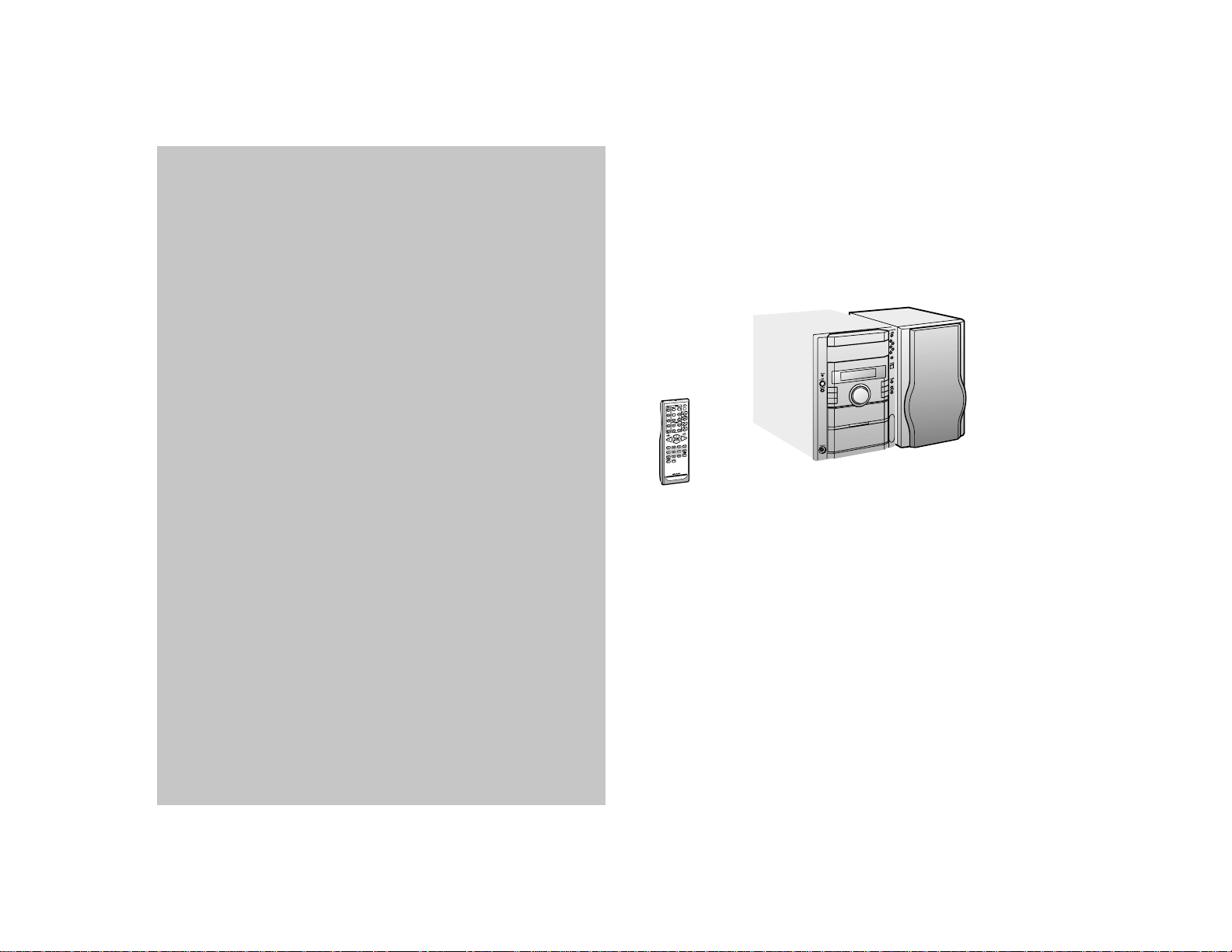
MICRO COMPONENT SYSTEM
XL-HP505 Micro Component System consisting of XL-HP505 (main unit)
and CP-HP505 (speaker system).
Page 2
XL-HP505
SPECIAL NOTES
CAUTION: TO REDUCE THE RISK OF ELECTRIC SHOCK,
DO NOT REMOVE COVER (OR BACK).
NO USER-SERVICEABLE PARTS INSIDE. REFER SERVICING TO QUALIFIED SERVICE PERSONNEL.
Explanation of Graphical Symbols:
The lightning flash with arrowhead symbol,
within an equilateral triangle, is intended to
alert the user to the presence of uninsulated
“dangerous voltage” within the product’ s enclosure that may be of sufficient magnitude
to constitute a risk of electric shock to persons.
The exclamation point within an equilateral
triangle is intended to alert the user to the
presence of important operating and maintenance (servicing) instructions in the literature accompanying the appliance.
NOTE
This equipment has been tested and found to comply with the limits for a
Class B digital device, pursuant to Part 15 of the FCC Rules. These
limits are designed to provide reasonable protection against harmful interference in a residential installation. This equipment generates, uses,
and can radiate radio frequency energy and, if not installed and used in
accordance with the instructions, may cause harmful interference to radio communications. However, there is no guarantee that interference
will not occur in a particular installation. If this equipment does cause
harmful interference to radio or television reception, which can be determined by turning the equipment off and on, the user is encouraged to try
to correct the interference by one or more of the following measures:
Reorient or relocate the receiving antenna.
Increase the separation between the equipment and receiver.
Connect the equipment into an outlet on a circuit different from that to
which the receiver is connected.
Consult the dealer or an experienced radio/TV technician for help.
WARNING
FCC Regulations state that any unauthorized changes or modifications
to this equipment not expressly approved by the manufacturer could void
the user's authority to operate this equipment.
NOTE
It is the intent of Sharp that this product be used in full compliance with
the copyright laws of the United States and that prior permission be obtained from copyright owners whenever necessary.
0210
Important Instruction
2
WARNING: TO REDUCE THE RISK OF FIRE OR ELECTRIC
SHOCK, DO NOT EXPOSE THIS APPLIANCE TO RAIN OR
MOISTURE.
Caution - use of controls or adjustments or performance
of procedures other than those specified herein may result in hazardous radiation exposure.
0012
0012
0012
For your assistance in reporting this unit in case of loss or theft,
FOR YOUR RECORDS
please record below the model number and serial number which
are located on the rear of the unit.
Please retain this information.
Model number .......................................................
Serial number .......................................................
Date of purchase .......................................................
Place of purchase .......................................................
0202
Page 3

IMPORTANT SAFETY INSTRUCTIONS
XL-HP505
1 Read Instructi ons - All the saf ety and operating instru ctions sho uld
be read before the product is operated.
2 Retain Instructions - The safety and operating instructions should be
retained for future reference.
3 Heed Warnings - All warnin gs on the produc t and in the operat ing
instructions should be adhered to.
4 Follow Instru ctions - All operating and use instructi ons should be
followed.
5 Cleaning - Unplug thi s product from the wall outlet bef ore cleaning.
Do not use liquid cleane rs or aeroso l cle aners. Use a damp clo th for
cleaning.
6 Attachments - Do not use attachments not recommended by the prod-
uct manufacturer as they may cause hazards.
7 Water and Moisture - Do not use this product near wat er - for ex-
ample, near a bath tub , wash bow l, kitchen sin k, or laundr y tub; in a
wet basement; or near a swimming pool; and the like.
8 Accessories - Do not pla ce this product on an uns table cart, stand,
tripod, bracket, or table. The product may fall, causing serious injury to
a child or adult, and serious dam age to the pro duct. Use onl y with a
cart, stand, tripod , bracket, or table recommend ed by the manufacturer, or sold with the produc t. Any mounting of the product should
follow the manufacturer’s instructions, and should use a mounting accessory recommended by the manufacturer.
9 A product and cart combin ation should be moved wit h
care. Quick stops, excessive force, and uneven surfaces
may cause the product and cart combination to overturn.
10 Ventilation - Slots and openings in the cabinet are provided for venti-
lation and to ens ure reliable ope rat ion of the pro duc t and to pro tec t it
from overheati ng, and these openin gs must not be blo cked or covered. The openings should never be blocked by placing the product on
a bed, sofa, rug, or other sim ilar surfac e. This product sho uld not be
placed in a built-in installation such as a bookcase or rack unless proper
ventilation is pro vided or the manufacturer ’s instructions hav e been
adhered to.
11 Power Sources - This product should be operated only from the type
of power source indicated on the marking label. If you are not sure of
the type of power supply to your home, consult your product dealer or
local power compan y. For produc ts intended to ope rate from batter y
power, or other sources, refer to the operating instructions.
12 Grounding or Pol arization - This product may be equipp ed with a
polarized alter nati ng- cur rent lin e plu g (a plu g hav ing one bla de wid er
than the other). Thi s plug will fit into the power outlet onl y one way.
This is a safety feature. If you are unable to insert the plug fully into the
outlet, try rev ersing the plug. If the plu g should still fai l to fit, contact
your electrician to replace your obsolete outlet. Do not defeat the safety
purpose of the polarized plug.
Alternate Warnings - This product is equipped with a three-wire
grounding-ty pe plug, a plu g having a thi rd (groundin g) pin. Thi s plug
will only fit into a grounding-type power outlet. This is a safety feature.
If you are unable to insert the plug into the outlet, contact your electrician to replace your obsolete outlet. Do not defeat the safety purpose
of the grounding-type plug.
13 Power-Cord Pro tection - Power-supply cords should be routed so
that they are not likely to be wal ked on or pinche d by items placed
upon or against the m, paying particular att ention to cords at plugs,
convenience receptacles, and the point where they exit from the product.
14 Protective Att achment Plug - The product is equ ipped with an at-
tachment plug having overload protection. This is a safety feature. See
Instruction Manual for replacement or resetting of protective device. If
replacement of the plug is required, be sure the service technician has
used a replaceme nt plug specif ied by the manufa cturer that has the
same overload protection as the original plug.
Important Instruction
3
Page 4

XL-HP505
IMPORTANT SAFETY INSTRUCTIONS
(continued)
15 Outdoor Antenna Grounding - If an outside antenna or cable system
is connected to the produc t, be sure the antenn a or cable system is
grounded so as to provide some protection against voltage surges and
built-up static charges. Article 810 of the National Electrical Code, ANSI/
NFPA 70, provides information with regard to proper grounding of the
mast and supporting structure, grounding of the lead-in wire to an antenna discharge unit, size of grounding conductors, location of antennadischarge unit, connection to grounding electrodes, and requirements
for the grounding electrode.
16 Lightning - For added protectio n for this produc t during a lightn ing
Important Instruction
storm, or when it is lef t unattended and unused for long periods of
time, unplug it from the wall outlet and disconnect the antenna or cable
system. This will pre vent dam age to the produc t due to lig htning and
power-line surges.
17 Power Lines - An outside antenna system should not be located in the
vicinity of overhead power lines or other electric light or power circuits,
or where it can fall into such power lines or circuits. When installing an
outside antenn a system, ext reme car e should be taken to kee p from
touching such power lin es or circuits as contac t with them might be
fatal.
18
Overloading - Do not overload wall out lets, ext ension cor ds, or integral
convenience receptacles as this can result in a risk of fire or electric shock.
Object and Liq uid Entry - Never pus h objects of any kind into thi s
19
product through openings as they may touch dangerous voltage points
or short-out parts that could result in a fire or electric shock. Never spill
liquid of any kind on the product.
20 Servicing - Do not attempt to service this product yourself as opening
or removing cov ers may expose you to dangerous vol tage or other
hazards. Refer all servicing to qualified service personnel.
21 Damage Requiring Service - Unplug this product from the wall outlet
and refer servic ing to qualif ied ser vice person nel und er the follow ing
conditions:
a) When the power-supply cord or plug is damaged,
b)If liquid has been spilled, or objects have fallen into the product,
c) If the product has been exposed to rain or water,
d)If the pro duct does not ope rat e normally by fol low ing the operating
instructions . Adjust only tho se contro ls tha t are covere d by the operating instructions as an improper adjustment of other controls may
result in damage and will often require extensive work by a qualified
technician to restore the product to its normal operation,
e) If the product has been dropped or damaged in any way, and
f) When the product exh ibits a distin ct change in perfor mance - this
indicates a need for service.
22 Replacement Par ts - When rep laceme nt parts are requir ed, be sure
the service techni cian has used replaceme nt parts specified by the
manufacturer or have the same characterist ics as the original part.
Unauthorized substitution s may result in fire, ele ctric shock, or other
hazards.
23 Safety Check -
4
Page 5
ENERGY STAR® Program Information
As an ENERGY STAR® Partner, SHARP has determined that this
product meets the
ENERGY STAR® is a U.S. registered mark.
WHY PURCHASE
Many Electrical /Electronic Products use energy both when they are on
and when they are off. Americans spend more than $3 billion a year on
energy consumed by home electronic products when they are not in
use. The new
ergy “leakage” by up to 75 percent. Ultimately, this will mean more than
$1 billion a year in energy savings for consumers.
The energy savings will help reduce the burning of fossil fuels and the
related carbon dioxide pollution that contributes to global warming.
If every American family replaced their electronic equipment with
ENERGY ST AR® labeled models, it would reduce air pollution equiva-
lent to eliminating more than two million cars.
By using
your electric bills and use less energy.
That makes good economic sense and it’s good for our environment.
To comply with the
please cancel the demonstration mode, as described on page .
ENERGY STAR® is a U.S. registered mark.
ENERGY ST AR® guidelines for energy ef ficiency .
ENERGY STAR® LABELED PRODUCTS?
ENERGY STAR® labeled models will reduce that en-
ENERGY ST AR® labeled products, you will save money on
ENERGY STAR® standards mentioned above,
12
0209
Contents
Page
! General Information
Precautions . . . . . . . . . . . . . . . . . . . . . . . . . . . . . . . . . . . . . . . . . 6
Controls and ind ic a t or s . . . . . . . . . . . . . . . . . . . . . . . . . . . . .7 - 9
! Preparation for Use
System connect ions . . . . . . . . . . . . . . . . . . . . . . . . . . . . . .10 - 12
! Basic Operation
Remote cont r ol . . . . . . . . . . . . . . . . . . . . . . . . . . . . . . . . . . . . . 13
General contr ol . . . . . . . . . . . . . . . . . . . . . . . . . . . . . . . . . . . . . 14
Setting the cloc k . . . . . . . . . . . . . . . . . . . . . . . . . . . . . . . . . . . . 15
! CD Playback
Listening to a CD (CDs) . . . . . . . . . . . . . . . . . . . . . . . . . . . . 16, 17
Advanced CD playback . . . . . . . . . . . . . . . . . . . . . . . . . . . .18 - 20
! Radio
Listening to the r ad io . . . . . . . . . . . . . . . . . . . . . . . . . . . . . 21, 22
! Tape Playback
Listening to a cassette tape . . . . . . . . . . . . . . . . . . . . . . . . 23, 24
! Tape Recording
Recording on a cassette tape . . . . . . . . . . . . . . . . . . . . . . .24 - 26
! Advanced Features
Timer and sleep operation . . . . . . . . . . . . . . . . . . . . . . . . .27 - 30
Enhancing your system . . . . . . . . . . . . . . . . . . . . . . . . . . . 31, 32
! References
Troubleshooti ng c ha r t . . . . . . . . . . . . . . . . . . . . . . . . . . . . .32 - 34
Maintenance . . . . . . . . . . . . . . . . . . . . . . . . . . . . . . . . . . . . . . . . 34
Specificati ons . . . . . . . . . . . . . . . . . . . . . . . . . . . . . . . . . . . . . . 35
CONSUMER LIMITED WARRANTY . . . . . . . . . . . . . .Back cover
XL-HP505
Important Instruction
5
Page 6
XL-HP505
Precautions
! General
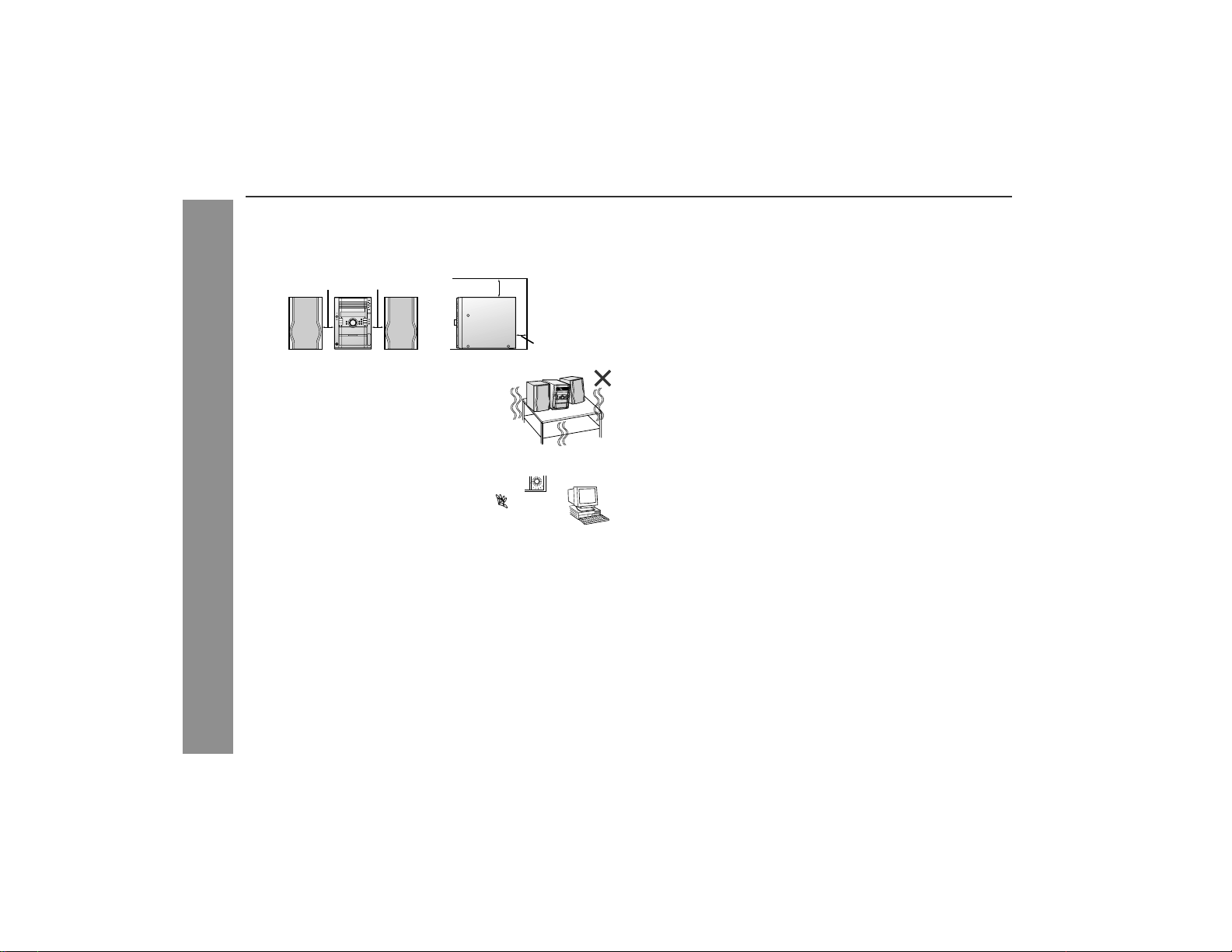
" Please ensure that the equipment is posi tioned in a well-venti-
lated area and ensure that there is at least 4" (10 cm) of free
space along the sides, top and back of the equipment.
4" (10 cm) 4" (10 cm)
" Use the unit on a firm, level surface free from
vibration.
" Keep the unit away from direct sunlight,
strong magnetic fields, excessive dust,
humidity and electronic/electrical equipment (home computers, facsimiles, etc.)
which generate electrical noise.
" Do not place anything on top of the unit.
General Information
" Do not expose the unit to moi sture, to temperatures higher tha n
140°F (60°C) or to extremely low temperatures.
" If your system does not work properly, disconnect the AC power
cord from the AC outlet. Plug the AC power cord back in, and
then turn on your system.
" In case of an electrical storm, unplug the
unit for safety.
4" (10 cm)
4" (10 cm)
" This unit shoul d only be used within the range of 41°F - 95°F
(5°C - 35°C).
Warning:
The voltage used must be the same as that specified on this unit.
Using this product with a higher voltage other than that which is
specified is dangerous and may result in a fire or other type of accident causing damage. SHARP will not be held responsible for any
damage resulting from use of this unit with a voltage other than that
which is specified.
! Volume control
The sound level at a given volume setting d epends on speaker efficiency, location and various other f actors. It is advisable to avoid
exposure to high volume levels, which occurs while t urning the un it
on with the volume control setting up high, or whil e continually listening at high volumes.
6
Page 7
Controls and indic ators
XL-HP505
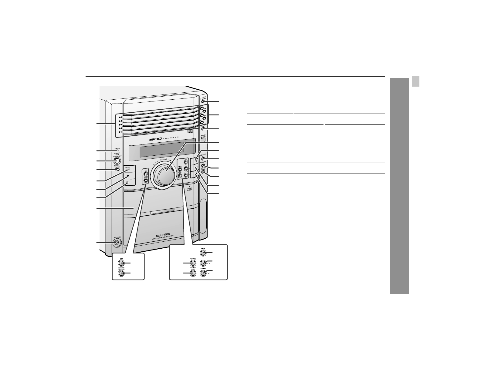
! Front panel
1.Disc Trays . . . . . . . . . . . . . . . . . . . . . . . . . . . . . . . . . . . . . . . 16
10
11
1
12
13
2
3
4
5
6
7
14
15
16
17
18
19
8
9
2.Timer Set Indicator . . . . . . . . . . . . . . . . . . . . . . . . . . . . . . . 28
3.Power On/Stand-by B utton . . . . . . . . . . . . . . . . . . . . . . . . . 14
4.Clock/Timer Button
5.CD Track Down or Fast Reverse, Tape Fast Wind, Tuner
Preset Down, Time Down Button . . . . . . . . . . . . . . 15, 17, 24
6.Tape Reverse Play But ton . . . . . . . . . . . . . . . . . . . . . . . . . . 23
7.Tape Reverse Mode Select But to n . . . . . . . . . . . . . . . . . . . 23
8.Cassette Compartment . . . . . . . . . . . . . . . . . . . . . . . . . . . . 23
9.Headphone Jack . . . . . . . . . . . . . . . . . . . . . . . . . . . . . . . . . 31
10.Disc Tray Open/Close Button
11.Disc Number Select Buttons . . . . . . . . . . . . . . . . . . . . . . . . 16
12.CD Direct Play Button
13.Volume Control . . . . . . . . . . . . . . . . . . . . . . . . . . . . . . . . . . 14
14.CD Track Up or Fast Forward, Tape Fast Wind, Tuner Preset
Up, Time Up Button . . . . . . . . . . . . . . . . . . . . . . . . . 15, 17, 24
15.Memory/Set Button . . . . . . . . . . . . . . . . . . . 15, 20, 22, 27, 30
16.Equalizer Mode Select Button . . . . . . . . . . . . . . . . . . . . . . 14
17.Extra Bass/Demo Mode Button . . . . . . . . . . . . . . . . . . 12, 14
18.CD Play or Repeat, Tape Forward Play Button . . . 16, 19, 23
19.CD or Tape Stop Button . . . . . . . . . . . . . . . . . . . . . . . . 17, 24
20.CD Button . . . . . . . . . . . . . . . . . . . . . . . . . . . . . . . . . . . . . . . 16
21.Tuner (Band) Button . . . . . . . . . . . . . . . . . . . . . . . . . . . . . . 21
22.Tape Button . . . . . . . . . . . . . . . . . . . . . . . . . . . . . . . . . . . . . 23
23.Video/Auxiliary Button . . . . . . . . . . . . . . . . . . . . . . . . . . . . 31
24.Tape Record Pause Button . . . . . . . . . . . . . . . . . . . . . . 25, 26
25.Tuning Up Button . . . . . . . . . . . . . . . . . . . . . . . . . . . . . . . . . 21
26.Tuning Down Button . . . . . . . . . . . . . . . . . . . . . . . . . . . . . . 21
. . . . . . . . . . . . . . . . . . . . . . . . . 15, 27, 30
. . . . . . . . . . . . . . . . . . . . . . . 16
. . . . . . . . . . . . . . . . . . . . . . . . . . . . . 18
Reference page
General Information
24
20
21
22
23
25
26
7
Page 8
XL-HP505
Controls and indicators (continued)
General Information
76321 4 5
1089
14
1211 13
15 16 17
4
5
6
7
1
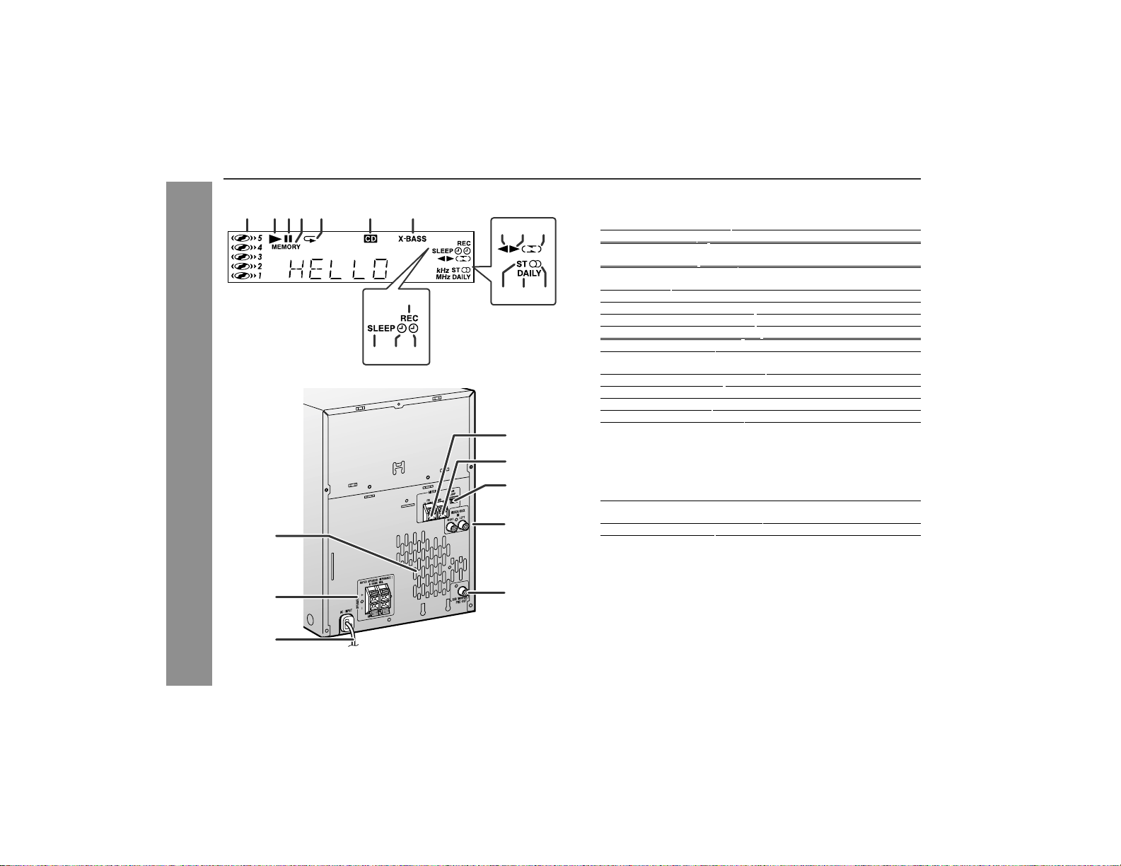
1.Disc Number Indicators
2.CD Pl ay Indicator . . . . . . . . . . . . . . . . . . . . . . . . . . . . . . . . . 16
3.CD Pause Indicator . . . . . . . . . . . . . . . . . . . . . . . . . . . . . . . 17
4.Me mory Indicator . . . . . . . . . . . . . . . . . . . . . . . . . . . . . . . . . 20
5.CD Repeat Play Indicator . . . . . . . . . . . . . . . . . . . . . . . . . . . 19
6.CD Indicator . . . . . . . . . . . . . . . . . . . . . . . . . . . . . . . . . . . . . 16
7.Extra Bass Indicator . . . . . . . . . . . . . . . . . . . . . . . . . . . . . . . 14
8.Tape Reverse Play Indicator . . . . . . . . . . . . . . . . . . . . . . . . 23
9.Tape Forward Play Indicator . . . . . . . . . . . . . . . . . . . . . . . . 23
10.Tape Reverse Mode Indicator . . . . . . . . . . . . . . . . . . . . . . . 23
11.FM Stereo Mode Indicator . . . . . . . . . . . . . . . . . . . . . . . . . . 21
12.Daily Timer Indicator . . . . . . . . . . . . . . . . . . . . . . . . . . . . . . 28
13.FM Stereo Receiving Indicator . . . . . . . . . . . . . . . . . . . . . . 21
14.Tape Record Indicator . . . . . . . . . . . . . . . . . . . . . . . . . . . . . 25
15.Sleep Indicator . . . . . . . . . . . . . . . . . . . . . . . . . . . . . . . . . . . 30
16.Timer Play Indicator . . . . . . . . . . . . . . . . . . . . . . . . . . . . . . . 28
17.Time r Recording Indicator . . . . . . . . . . . . . . . . . . . . . . . . . . 28
! Rear panel
1.Cooling Fan . . . . . . . . . . . . . . . . . . . . . . . . . . . . . . . . . . . . . . 12
2.Speaker Te rminal s . . . . . . . . . . . . . . . . . . . . . . . . . . . . . . . . 11
3.AC Power Cord . . . . . . . . . . . . . . . . . . . . . . . . . . . . . . . . . . . 12
4.FM 75 Ohms Antenna Terminal
5.FM Antenna Ground Terminal . . . . . . . . . . . . . . . . . . . . . . . 11
6.AM Loop Aerial Jack . . . . . . . . . . . . . . . . . . . . . . . . . . . . . . 11
7.Video/Auxiliary (Audio Signal) Input Jacks . . . . . . . . . . . . 31
8.Subwoofer Pre-output Jack . . . . . . . . . . . . . . . . . . . . . . . . . 32
. . . . . . . . . . . . . . . . . . . . . . . . . . . . 18
. . . . . . . . . . . . . . . . . . . . . . 11
Reference page
Reference page
! Speaker system
! Display
2
8
3
8
Page 9
XL-HP505
1
8
9
15 20
2
3
10
11
12
13
16
17
18
19
21
22
23
24
4
5
14
6
7
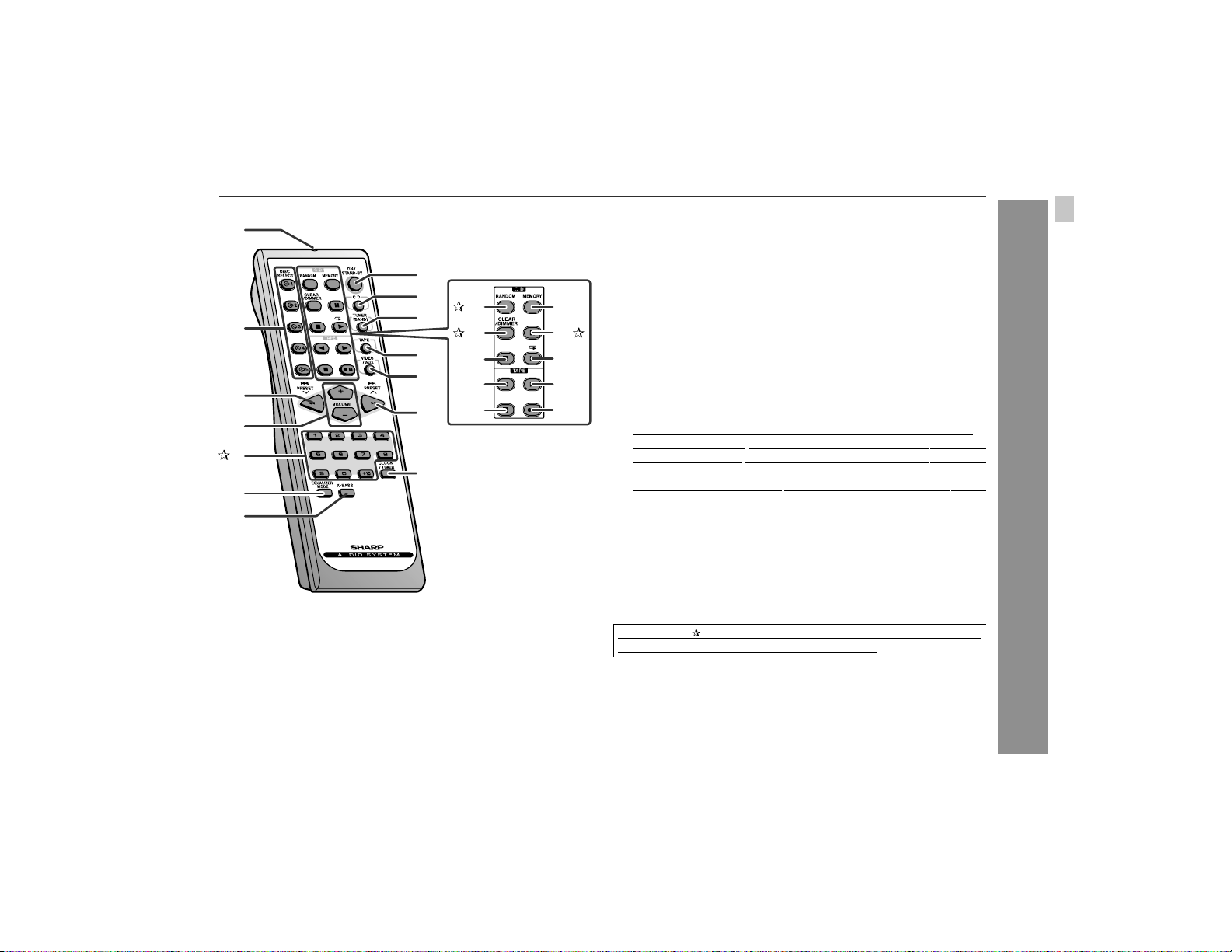
! Remote control
1.Re mote Control Transmitter . . . . . . . . . . . . . . . . . . . . . . . . . . 13
2.Disc Number Select Buttons . . . . . . . . . . . . . . . . . . . . . . . . . 16
3.CD Track Down or Fast Reverse, Tape Fast Wind, Tuner Preset
Down, Time Down Button . . . . . . . . . . . . . . . . . . . . . 15, 17, 24
4.Volume Up and Down Buttons . . . . . . . . . . . . . . . . . . . . . . . . 14
5.Disc Direct Search Buttons . . . . . . . . . . . . . . . . . . . . . . . . . 18
6.Equalizer Mode Select Button . . . . . . . . . . . . . . . . . . . . . . . . 14
7.Extra Bass Button . . . . . . . . . . . . . . . . . . . . . . . . . . . . . . . . . 14
8.Power On/Stand-by Button . . . . . . . . . . . . . . . . . . . . . . . . . . 14
9.CD Button . . . . . . . . . . . . . . . . . . . . . . . . . . . . . . . . . . . . . . . 16
10.Tuner (Band) Button . . . . . . . . . . . . . . . . . . . . . . . . . . . . . . . 21
11.Tape But ton . . . . . . . . . . . . . . . . . . . . . . . . . . . . . . . . . . . . . . 23
12.Video/Auxiliary Button . . . . . . . . . . . . . . . . . . . . . . . . . . . . . . 31
13.CD Track Up or Fast Forward, Tape Fast Wind, Tuner Preset
Up, Time Up Button . . . . . . . . . . . . . . . . . . . . . . . . . . 15, 17, 24
14.Clock/Timer Button . . . . . . . . . . . . . . . . . . . . . . . . . . 15, 27, 30
15.CD Random Button . . . . . . . . . . . . . . . . . . . . . . . . . . . . . . . 19
16.CD Clear/Dimmer Button
17.CD Stop Button . . . . . . . . . . . . . . . . . . . . . . . . . . . . . . . . . . . 17
18.Tape Reverse Play Button . . . . . . . . . . . . . . . . . . . . . . . . . . . 23
19.Tape Stop Button . . . . . . . . . . . . . . . . . . . . . . . . . . . . . . . . . . 24
20.CD Memory Button . . . . . . . . . . . . . . . . . . . . . . . . . . . . . . . . 20
21.CD Pause Button . . . . . . . . . . . . . . . . . . . . . . . . . . . . . . . . . 17
22.CD Play or Repeat Button . . . . . . . . . . . . . . . . . . . . . . . . 16, 19
23.Tape For ward Play Button . . . . . . . . . . . . . . . . . . . . . . . . . . . 23
24.Tape Record Paus e Button . . . . . . . . . . . . . . . . . . . . . . . 25, 26
Buttons with " " mark in the illustration or high lighted in bold on t he
list can be operated on the remote control only.
. . . . . . . . . . . . . . . . . . . . . . . . 14, 20
Reference page
General Information
9
Page 10
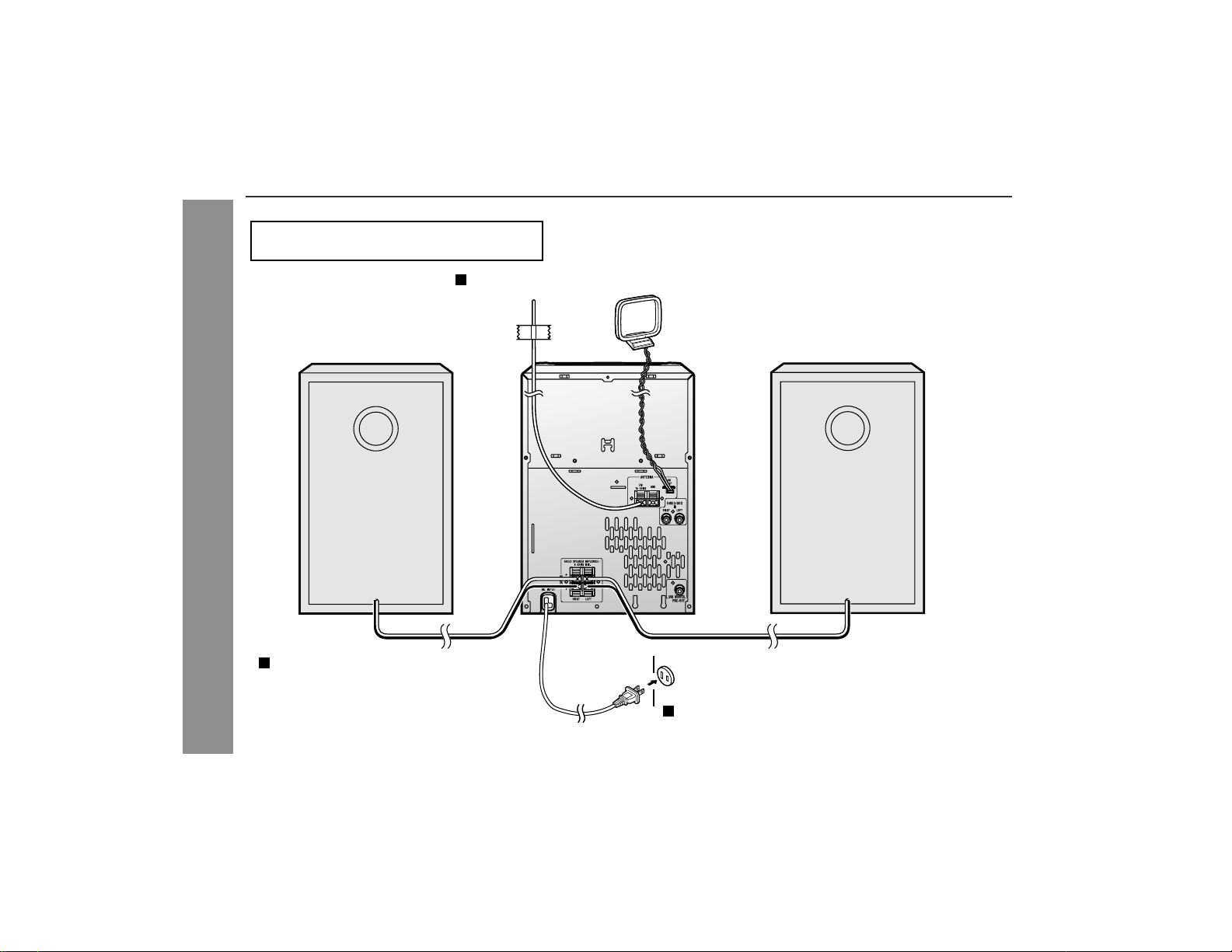
XL-HP505
System connections
Make sure to unplug the AC power cord before
connecting the speaker wires.
Antenna connection (see page 11)
Preparation for Use
Speaker connection (see page 11)
Right speaker
FM antenna
AM loop antenna
Left speaker
AC outlet
(AC 120 V, 60 Hz)
Connecting the AC power cord (see page 12)
10
Page 11
XL-HP505
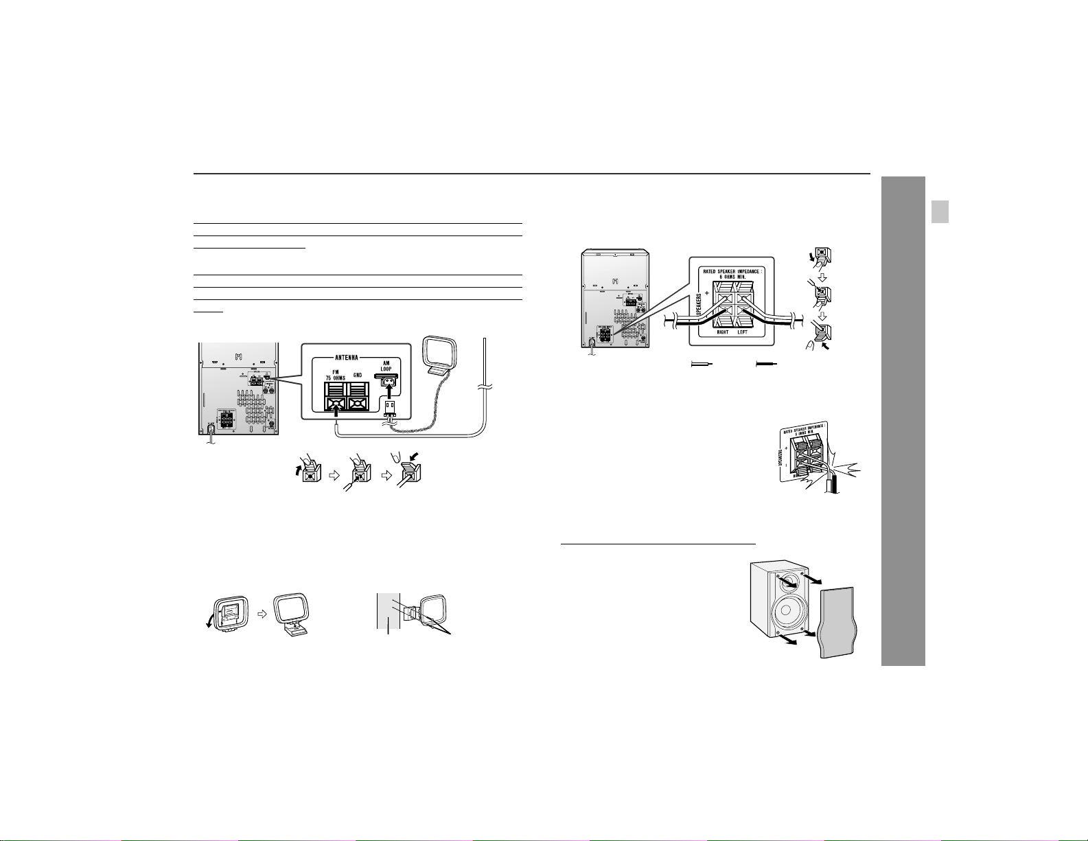
! Antenna connection
Supplied FM antenna:
Connect the FM antenna wire to the FM 75 OHMS terminal and
position the FM antenna wire in the direction where the strongest
signal can be received.
Supplied AM loop antenna:
Connect the AM loop antenna to the AM LOOP jack. Pos ition the
AM loop antenna for optimum reception. Place the AM loop antenna
on a shelf, etc., or attach it to a stand or a wall with screws (not supplied).
Note:
Placing the antenna on the unit o r near the AC power cord may
cause noise pickup. Place the antenna away from the unit for better
reception.
Installing the AM loop antenna:
< Assembling > < Attaching to the wall >
! Speaker connection
Connect the black wire to the minus (-) terminal, and the red wire to
the plus (+) terminal.
BlackRed
Caution:
" Use speakers with an impedance of 6 ohms or more, as lower im-
pedance speakers can damage the unit.
Do not mistake the right and the left chan-
"
nels. The right speaker is the one on the right
side when you face the unit.
" Do not let the bare speaker wires touch
each other.
" Do not allow any objects to fall into or to be
placed in the bass reflex ducts.
" Do not stand or sit on the speakers. You may
be injured.
Incorrect
! Speaker grilles are removable
Make sure nothing comes into contact
with the speaker diaphragms when you
remove the speaker grilles.
Preparation for Use
Wall Screws (not supplied)
11
Page 12

XL-HP505
System connections (continued)
! Connecting the AC power cord
After checking all the connections have been made correctly, plug
the AC power cord of this unit into the AC outlet. If you plug i n the
unit first, the unit will enter the demonstration mode.
Notes:
The unit will start the tape initialization when plugged in to the AC
"
outlet. During this process, an initializing sound will be heard and
the unit cannot be turned on. Wait until the process is finished.
Unplug the AC power cord from the AC outlet if the unit will not
"
be in use for a prolonged period of time.
Preparation for Use
Cooling fan:
This product is equipped with a cooling fan inside, which begins to
run at a specified volume level for better heat radiation.
! Outdoor FM antenna
Use an outdoor FM antenna if you require bet ter rec eption. Consu lt
your dealer.
Note:
When an outdoor FM antenna is used, disconnect the supplied FM
antenna wire.
! Demonstration mode
12
Page 13

Remote control
XL-HP505
! Battery installation
Use 2 "AA" size batteries (UM/SUM-3, R6, HP-7 or similar).
Batteries are not included.
1 Remove the battery cover.
2 Insert the batteries according to the direction indicated in
the battery compartment.
When inserting or removing the batteries, push them toward the
battery terminals.
3 Replace the cover.
Precautions for battery use:
Replace all old batteries with new ones at the same time.
"
Do not mix old and new batteries.
"
Remove the batteries if the unit will not be used for long periods
"
of time. This will prevent potential damage due to battery leakage.
Caution:
Do not use rechargeable batteries (nickel-cadmium battery, etc.).
"
Installing the batteries incorrec tly may cause t he u nit to malfunc -
"
tion.
Notes concerning use:
" Replace the batteries if the operating distance is reduced or if the
operation becomes erratic.
" Periodically clean the transmitter on the remote control and the
sensor on the unit with a soft cloth.
" Exposing the s ensor on the un it to str ong ligh t may i nte rfere wi th
operation. Change the lighting or the direction of the unit.
" Keep the remote c ontrol away from moisture, heat, shock, and
vibrations.
! Test of the remote control
Check the remote control after checking all the connections (see
pages 10 - 12).
Point the remote control directly at the remote sensor on the unit.
The remote control can be used within the range shown below:
Press the ON/STAND-BY button. Does the power turn on? Now,
you can enjoy music.
Basic Operation
13
Page 14

XL-HP505
General control
! Volume control
Main unit operation:
When the VOLUME control is turned clockwise, the volume will
increase. When it is turned counterclockwise, the volume will
decrease.
Remote control operation:
Press the VOLUME (+ or -) button to increase or decrease the volume.
! Bass control
When the power is first turned on, the unit will enter the extra bass
mode which emphasizes the bass frequencies, and "X-BASS" will
appear. To cancel the extra bass mode, press the X-BASS/DEMO
(X-BASS) button.
Basic Operation
14
! To turn the power on
Press the ON/STAND-BY button to turn the power on.
After use:
Press the ON/STAND-BY button to enter the power stand-by
mode.
! Illumination light control
When the power is turned on, light illuminates around the volume
control. To turn on/off the light, hold down the CLEAR/DIMMER button on the remote control more than 2 seconds.
! Equalizer
When the EQUALIZER (EQUALIZER MODE) button is pressed, the
current mode setting will be displayed. To change to a different
mode, press the EQUALIZER (EQUALIZER MODE) button repeatedly until the desired sound mode appears.
Page 15

Setting the clock
5
Press the or button to adjust the hour and then press
the MEMORY/SET button.
Press the or button once to advance the time by 1 hour.
Hold it down to advance continuously.
6
Press the or button to adjust the minutes and then
press the MEMORY/SET button.
XL-HP505
In this example, the clock is set for the 12-hour (AM 12:00) display.
1
Press the ON/STAND-BY button to turn the power on.
2
Press the CLOCK/TIMER button.
3
Within 10 seconds, press the or button to select
"CLOCK", and press the MEMORY/SET button.
4
Press the or button to select 12-hour or 24-hour display and then press the MEMORY/SET button.
"AM 12:00" The 12-hour display will appear.
(AM 12:00 - PM 11:59)
"AM 0:00" The 12-hour display will appear.
(AM 0:00 - PM 11:59)
"0:00" The 24-hour display will appear.
(0:00 - 23:59)
Press the or button once to advance the time by 1
minute. Hold it down to change the time in 5-minute intervals.
To confirm the time display:
1 Press the CLOCK/TIMER button.
2 Within 10 seconds, press the or button until the current
time is displayed.
The time display will appear for about 10 seconds.
Note:
The "CLOCK" or time will flash t o confirm the time display when the
AC power supply is restored aft er a power f ailure or unpluggi ng the
unit. If incorrect, readjust the clock as follows.
To readjust the clock:
Perform "Setting the cl ock" from step 1. If the time display i s flashing, step 4 (for selecting the 12-hour or 24-hour display) will be
skipped.
To change the 12-hour or 24-hour display:
1 Clear all the programmed contents. [Refer to "Clearing all the
memory (reset)" on page 33 for details.]
2 Perform "Setting the clock" from step 1.
Note:
The clock can also be set with the remote control.
Basic Operation
15
Page 16

XL-HP505
Listening to a CD (CDs)
This system can also play au dio CD-R and CD-RW discs, but cannot record.
Some audio CD-R-RW discs may not be playable due to the state of
the disc or the device that was used for recording.
CD Playback
! CD playback
16
Page 17

XL-HP505
" Playback will begin from track 1 on the DISC 1. After that disc fin-
ishes playing, the next disc will automatically play.
" After t he last track on the fifth disc is play ed, the CD player stops
automatically.
" When there is no CD in one of the disc trays (1 - 5), the empty
tray will be skipped to the next tray with a CD.
To exchange other CDs while playing a disc:
Press one of the 1 - 5 buttons for the stopped disc and withi n 5
seconds, press the OPEN/CLOSE button and exchange discs.
To remove the CDs:
In the stop mode, press the 1 - 5 bu tton and within 5 se conds,
press the OPEN/CLOSE button.
Caution:
" Do not place two CDs in one disc tray.
" Do not play discs with special shapes (heart- or octagon-
shaped). It may cause malfunctions.
" Do not push the disc tray while it is moving.
" If the power fa ils while the tray is open, wait until the power is
restored.
" If the disc tray is stopped with force, "ER-CD20" will appear on
the display for 3 seconds and the uni t will not function. If this
occurs, press the ON/STAND-BY button to enter the power
stand-by mode and then turn the power on again.
" If TV or radio i nterferenc e occurs during CD o perati on, move t he
unit away from the TV or radio.
" If a disc is damaged, dirty, or loaded upside down, the disc will
skip.
Auto power on function:
When you press any of the following buttons, the unit turns on.
" CD button (m ain unit and remote control): The uni t turns on and
the "CD" function is activated.
" CD / button on the remote control: The unit turns on and CD
playback starts (regardless of the last function).
" / button on the main unit: The unit tu rns on and playback of
the last function starts (CD/TAPE/TUNER/VIDEO).
! Various CD functions
Function Main unit Remo te
Play Press in the stop
Stop Press in the playback
Pause Press in the playback
Fast forward/Fast
reverse
Cue/Review Press and hold down
Notes:
" Cue/review and fast forward/fast reverse are possible only within
individual discs.
" When the end of the last track is reached during fast forward, "
END" will appear on the display and CD operation will be paused.
When the beginning of the first track is reached during fast reverse, the unit will enter the playback mode.
( : Last track number)
control
Operation
mode.
mode.
mode. Press the /
button to resume playback from the paused
point.
Press in the playback
or stop mode.
Select the desired
track in the stop mode.
Playback starts from
that track.
in the playback mode.
Release the button to
resume playback.
CD Playback
17
Page 18

XL-HP505
Advanced CD playback
! To specify a disc to play
You can play a disc by specifying the disc number.
1
Press one of the 1 - 5 buttons to select the desired disc.
Selected disc number
2
Within 5 seconds, press the CD DIRECT PLAY button on
the main unit.
CD Playback
Only the chosen disc will be played and stopped automatically.
Note:
If the button of t he di sc tr ay wi th n o disc is p ress ed , play ba ck will n ot
start and the disc indicator will go out.
To stop playback:
Press the (CD ) button.
! Direct track search
By using the direct search buttons, the desired tracks on the current
disc can be played.
Use the direct search buttons on
the remote control to select the desired track while playing the selected disc.
Selected track number
" The direct search buttons allow you to select up to number 9.
" When selecting number 10 or more, use the "+10" button.
A. For example, to choose 13
1 Press the "+10" button once.
2 Press the "3" button.
B. For example, to choose 30
1 Press the "+10" button three times.
2 Press the "0" button.
If the direct search buttons are press ed while the disc is stopped,
press the / button to start the desired track on the current disc.
Notes:
A track number higher than the number of tracks on the disc can-
"
not be selected.
During random play, direct search is not possible.
"
18
Page 19

XL-HP505
! Repeat play
Repeat play can play all 5 discs, all t racks on a chosen disc, or a
programmed sequence continuosly.
To repeat all tracks on up to 5 discs:
Press the / button twice.
To repeat desired tracks:
Perform steps 1 - 6 in the "Programmed play" section on page 20
and then press the / button.
To cancel repeat play:
Press the / button again.
" " will go out.
To repeat all tracks on the chosen disc:
1 Press one of the 1 - 5 buttons.
2 Within 5 seconds, press the CD DIRECT
PLAY button twice.
To cancel repeat play:
Press the CD DIRECT PLAY button again.
" " will go out.
! Random play
The tracks on the disc(s) can be played in random order automati cally.
To random play all tracks on up to 5 discs:
Press the RANDOM button on the remote control.
To random play all tracks on the chosen disc:
1 Press one of the 1 - 5 buttons.
2 Within 5 seconds, press the CD DIRECT PLAY button.
3 Press the RANDOM button on the remote control.
To cancel random play:
Press the / or CD DIRECT PLAY button.
Notes:
" If you press the button during random play, you can move to
the track selected next by the random operation. On the other
hand, the button does not allow you to move to the previous
track. The beginn in g of the tra c k being played will be located.
In random play, the CD player will select and play t racks auto-
"
matically. (You cannot select the order of the tracks.)
CD Playback
Caution:
After performing repeat or random pl ay, b e sur e to pres s the (CD
) button. Otherwise, the disc(s) will play continuously .
19
Page 20

XL-HP505
Advanced CD Playback (continued)
! Programmed play
You can choose up to 32 selections for playback in the order you
like.
1
While in the stop mode, press the
MEMORY/SET (M EMORY) button
to enter the programming save
mode.
2
Press one of the one o01( 301( 31.9(b)- 0513Tn)10.7(r815.1(n 4.9)-5.9(t))-13.3(O)-8.t(n)) imri4u.tnn4 ref422.74(n)n(n)(4 re4g.560513Tn)104g.56 30ant
CD Playback
To cancel the programmed play mode:
While in the stop mode and the "MEMORY" indicator is lit, press the
CLEAR/DIMMER button on the remote control. The "MEMORY"
indicator will disappear and all the programmed contents will be
cleared.
Adding tracks to the program:
If a program has been previously stored, the "MEMORY" indicator
will be displayed. Then follow steps 1 - 6 to add t racks. The new
tracks will be stored after the last track of the original program.
To check which tracks are programmed:
While the unit is stopped in the programmed play mode, press the
or button.
Notes:
When a disc with programmed tracks is ejecte d, the program is
"
automatically canceled.
Even if you press the ON/STAND-BY button to enter the stand-by
"
mode or change the function from CD to another, the programmed selections will no t be clea r ed .
During the program operation, random play is not possible.
"
During programmed play, the CD DIRECT PLAY buttons will not
"
work.
20
Page 21

Listening to the radio
Auto power on function:
When you press any of the following buttons, the unit turns on.
" TUNER (BAND) button (main unit and remote control): The unit
turns on and the "TUNER" function is activated.
" / button on the main unit: The unit tu rns on and playback of
the last function starts (CD/TAPE/TUNER/VIDEO).
! Tuning
Notes:
" When radio interference occurs, auto scan tuning may stop auto-
matically at that point.
" Auto scan tuning will skip weak si gnal stat ions .
" To stop the auto tuning, press the TUNING button again.
! To receive an FM stereo transmission
Press the TUNER (BAND) button to display the "ST" indicator.
" " " will appear when an FM broadcast is in stereo.
" If the FM reception i s weak, p ress the TUNER (BAND) butt on to
extinguish the "ST" indicator. The reception changes to monaural, and the sound becomes clearer.
XL-HP505
Radio
21
Page 22

XL-HP505
Listening to the radio (continued)
Radio
22
! Memorizing a station
You can store 40 AM and FM stations in memory and recall them at
the push of a button. (Preset tuning)
1
Perform steps 1 - 3 in "Tuning" on page 21.
2
Press the MEMORY/SET (MEMORY) button to enter the
preset tuning saving mode.
3
Within 30 seconds, press the PRESET ( or ) button to
select the preset channel number.
Store the stations in memory, in order, starting with preset
channel 1.
4
Within 30 seconds, press the MEMORY/SET (MEMORY)
button to store that station in memory.
If the "MEMORY" and preset number indicators go out before
the station is memorized, repeat the operation from step 2.
5
Repeat steps 1 - 4 to set other stations, or to change a preset station.
When a new station is stored in memory, the station previously
memorized will be erased.
Note:
The backup function protects the memorized stations for a few
hours should there be a power failure or the AC power cord disconnection.
! To recall a memorized station
Press the PRESET ( or ) button for less than 0.5 secon ds to select the desired station.
! To scan the preset stations
The stations saved in memory can be scanned aut omatically. (Preset memory scan)
1 Press the PRESET ( or ) button for more than 0.5 seconds.
The preset number will flash and the programmed stations will be
tuned in sequentially, for 5 seconds each.
2 Press the PRESET ( or ) button again when the desired sta-
tion is located.
! To erase entire preset memory
1 Press the ON/STAND-BY button to enter the stand-by mode.
2 While pressing down the button and the X-BASS/DEMO but-
ton, press the CLOCK/TIMER button until "TUNER CL" appears.
Page 23

Listening to a cassette tape
XL-HP505
Before playback:
" For playback, use normal or low-noise tapes for the
best sound. (Metal or CrO tapes are not recommended.)
Do not use C-120 tapes or poor-quality tapes, as
"
they may cause malfunctions.
Before loading a tape into the cassette compartment,
"
tighten the slack with a pen or a pencil.
! Tape playback
Auto power on function:
When you press any of the following buttons, the unit turns on.
TAPE button (main unit and remot e control): The unit turns on
"
and the "TAPE" function is activated.
TAPE button on the remote control: The unit turns on and side
"
A playback starts (regardless of the last function).
/ button on the main unit: The unit turns on and pl ayback of
"
the last function starts (CD/TAPE/TUNER/VIDEO).
Tape Playback
23
Page 24

XL-HP505
Recording on a cassette tape
! Various tape functions
Function Main unit Remote
control
Side A playback
Side B playback
Stop Press in the playback
Fast forward/Fast
rewind
Operation
Press in the stop
mode.
Press in the stop
mode.
mode.
Press in the playback
or stop mode.
Tape Playback
Caution:
To remove the cassette, press the (TAPE ) button, and then
"
open the compartment.
Before changing from one tape operation to another, press the
"
(TAPE ) button.
If a power failure occurs during tape operation, the tape head will
"
remain engaged with the tape and the cassette door will not
open. In this case, wait until the power is restored.
Before recording:
" When recording important selections, make a preliminary test to
ensure that the desired material is properly recorded.
SHARP is not liable for damage or loss of your recording arising
"
from malfunction of this unit.
" The volume and sound controls can be adjusted with no effect
on the recorded signal (Variable Sound Monitor).
" For recording, use only normal tapes. Do not use metal or
CrO tapes.
Erase-prevention tab of cassette tapes:
When recording on a cassette tape, make sure that the erase-
"
prevention tabs are not removed. Cassettes have removable
tabs that prevent accidental recording or erasing.
" To protect the recorded sound, remove the tab after recording.
Cover the tab hole with adhesive tape to record on the tape without the tab.
Side A
Tab for side B
Tab for side A
24
Page 25

! Recording from a CD (CDs)
You can record the desired CD using the CD DIRECT PLAY button.
XL-HP505
Tape Recording
25
Page 26

XL-HP505
Recording on a cassette tape (continued)
Recording from several CDs continuously:
1 Perform steps 1 - 6 in "Recording from a CD (CDs)" on page 25.
2 Within 5 seconds, press the / ( ) button to record on side A,
or the button for side B.
To perform programmed recording:
1 Program discs and tracks. (See page 20.)
2 Press the button.
3 Press the / ( ) button to record on side A, or the button for
side B.
To stop recording:
Press the (TAPE ) button.
The CD and tape will stop.
Auto restart function:
If the recording side is switched f rom side A to B during re cording,
the system will record the interrupted track on side B from its beginning. The recording will be made without cutting the beginning of the
track on side B.
Tape Recording
! Recording from the radio
1
Tune in to the desired station. (See page 21.)
2
Load a cassette into the cassette compartment with side A
facing you.
Wind past the leader of the tape, on which recording cannot be
performed.
3
Press the button to choose one side or both sides.
... To record on both sides.
... To record on only one
side.
4
Press the button.
Recording will be paused.
5
Press the / ( ) button to record on side A, or the button for side B.
To record on both sides, begin with side A. (If recording is started from side B, the tape will not switch over to side A.)
To interrupt recording:
Press the butt on.
To resume recording, press the same recording button you pressed
in step 5. Other buttons do not allow resuming.
To stop recording:
Press the (TAPE ) button.
Note:
If you hear a whistling noise while recording an AM stat ion, move
the AM loop antenna.
26
! Erasing recorded tapes
1 Press the TAPE button.
2 Follow steps 2 - 5 in "Recording from the radio".
Page 27

Timer and sleep operation
The unit turns on and plays the desired source (CD, tuner, tape) at
the preset time.
The unit turns on and starts recording from the tuner at the preset
time.
This unit has 2 types of timer: ONCE T IMER and DAILY TIMER.
XL-HP505
Once timer: Once timer play and once timer recording works for
For example, if you are away but want to record a program on a radio station.
Daily timer:
For example, set the alarm to sound every morning.
Using the once timer and daily timer in combination:
For example, use the once timer to record a radio program, and use
the daily timer as an alarm clock.
1 Set the daily timer (pages 27 - 29).
2 Set the once timer (pages 27 - 29).
Start
Note:
When set times for the daily timer and once t imer overlap, the onc e
timer takes priority. Allow an interval of at least 1 mi nute between
operations.
one time only at a preset time.
Daily timer play and daily timer recording works at
the same preset time everyday.
1 minute or more
Daily timer
Stop Start Stop
Once timer
! Timer playback or timer recording
Before setting timer:
1 Check that the clock is set to the correct time (refer to page 15).
2 For timer playback: Load a cassette or discs to be played.
For timer recording: Load a cassette for recording in the cas-
1
Press the ON/STAND-BY button to turn the power on.
2
Press the CLOCK/TIMER button.
3
Within 10 seconds, press the or button to select
"ONCE" or "DAILY", and press the MEMORY/SET button.
Set the unit to the correct time if "ONCE" or "DAILY" does not
appear.
sette compartment.
Continued to the next page
Advanced Features
27
Page 28

XL-HP505
Timer and sleep operation (continued)
4
Within 10 seconds, press the or button to select
"ONCE SET" or "DAILY SET", and press the MEMORY/SET
button.
5
Press the or button to select "PLAY" or "REC", and
press the MEMORY/SET button.
" The "DAILY" indicator remains lit while setting the daily tim-
" The illustrati ons show the daily timer setting.
6
Press the or button to adjust the hour and then press
the MEMORY/SET bu t to n.
Advanced Features
The illustrations show the timer playback settin g in the daily timer mode.
7
Press the or button to adjust the minutes and then
press the MEMORY/SET button.
er.
White Red
9
Switch input with the or button, and then press the
MEMORY/SET button.
To select the timer playback source: CD, TUNER (BAND) or
TAPE.
To select the timer recording source: TUNER (BAND).
" When you select the tuner, select a station by pressing the
or button, and then press the MEMORY/SET button.
" If a station has not been programmed, " NO P.SET" will be
displayed and timer setting will be canceled.
10
Adjust the volume using the VOLUME control, and then
press the MEMORY/SET button.
Do not turn the volume up too high.
11
Press the ON/STAND-BY button to enter the power standby mode.
28
8
Set the time to finish as in steps 6 and 7 above.
Page 29

XL-HP505
12
When the preset time is reached, playback or recording will
start.
In the timer playback mode, the volume will increase gradually
until it reaches the volume you were listening to before your
system entered the timer stand-by mode.
13
When the timer end time is reached, the system will enter
the power stand-by mode automatically.
Once timer:
The timer will be canceled.
Daily timer:
The timer will operate at the same time every day. It will continue until the daily timer setting is canceled. Cancel the daily timer
when it is not used.
Note:
When performing timer playback or recording using another unit connected to the VIDEO/AUX IN jacks, select "VIDEO/AUX" in step 9.
This unit will turn on or enter the power stand-by mode automatically,
however, the connected unit will not turn on or off.
To check the timer setting:
1 In the timer stand-by mode, press the CLOCK/TIMER button.
2 Within 10 seconds, press the or button to select "ONCE" or
"DAILY", and press the MEMORY/SET button.
3 Within 10 seconds, press the or button to select " ON CE
CAL" or "DAILY CAL", and press the MEMORY/SET button.
The unit returns to the timer stand-by mode after displaying the
settings in order.
Canceling the timer playback or timer recording:
Timer is canceled by turning the power on while in the timer standby mode. The same operation can be performed in the following
procedure without turning the power on.
1 In the timer stand-by mode, press the CLOCK/TIMER button.
2 Within 10 seconds, press the or button to select "ONCE" or
"DAILY", and press the MEMORY/SET button.
3 Within 10 seconds, press the or button to select "ONCE
OFF" or "DAILY OFF", and press the MEMORY/SET button.
Timer will be canceled (the setting will not be canceled).
Reusing the timer:
Using the same setting;
The timer setting will be memorized once it is entered. To reuse the
same setting, perform the following operations.
1 Turn the power on and press the CLOCK/TIMER button.
2 Within 10 seconds, press the or button to select "ONCE" or
"DAILY", and press the MEMORY/SET button.
3 Within 10 seconds, press the or button to select "ONCE
ON" or "DAILY ON", and press the MEMORY/SET button.
Changing the setting;
Turn the power on, and repeat the operation fro m step 1 in "Timer
playback or timer recording".
Note:
The timer can also be set with the remote control.
Advanced Features
29
Page 30

XL-HP505
Timer and sleep operation (continued)
! Sleep operation
The radio, compact disc and cassette tape can all be turned off
automatically.
1
Play back the desired sound source.
2
Press the CLOCK/TIMER button.
3
Within 10 seconds, press the
or button to select
"SLEEP", and press the MEMORY/SET button.
4
Press the or button to select the time.
(Maximum: 3 hours - Minimum: 1 minute)
" 3 hours - 5 minutes 5-minute intervals
" 5 minutes - 1 minute 1-minute intervals
5
Press the MEMORY/SET button.
"SLEEP" will appear.
6
The unit will enter the power stand-by mode automatically
after the preset time has elapsed.
Advanced Features
The volume will be turned down 1 minute before the sleep operation finishes.
To confirm the remaining sleep time:
1 While "SLEEP" is indicated, press the CLOCK/TIMER button.
2 Within 10 seconds, press the or button to select "SLEEP
X : XX".
"X : XX" is sleep remaining time.
" The remaining sleep time is displayed for about 10 seconds.
" You can change the remaining sleep time while it is displayed by
pressing the MEMORY/SET button (steps 4 - 5).
To cancel the sleep operation:
Press the ON/STAND-BY button while "SLEEP" is indicated.
To cancel the sleep operation without setting the unit to the stand-by
mode, proceed as follows.
1 Press the CLOCK/TIMER button.
2 Within 10 seconds, press the or button to select "SLEEP
OFF", and press the MEMORY/SET button.
! To use timer and sleep operation together
You can play back the same source only (the function cannot be
switched).
1 Set the sleep time (see left, steps 1 - 5).
2 While the sleep timer is set, set the desired playback time
(steps 2 - 10, pages 27 - 28).
Sleep timer setting Timer playback setting
1 minute - 3 hours
Sleep operation will
automatically stop.
Caution:
When using the cassette deck, be sure the tape length is long
enough to perform both functions. If you want to sleep and wake up
listening to a tape, and the length of the tape is shorter than the
sleep timer setting, timer playback will not be possible.
Timer playback
start time
30
Page 31

Enhancing your system
XL-HP505
The connection cord is not included. Purchase a commercially available cord as shown below.
Auto power on function:
When you press any of the following buttons, the unit turns on.
" VIDEO/AUX button (main unit and remote control): The unit turns
on and the "VIDEO" function is activated.
" / button on the main unit: The unit tu rns on and playback of
the last function starts (CD/TAPE/TUNER/VIDEO).
! Listening to the playback sounds from VCR,
DVD, etc.
Note:
To prevent noise interference, place the unit away from th e television.
! To record on a tape
Advanced Features
! Headphones
" Before plugging in or unplugging the headphones, reduce the
volume.
" Be sure your headphones have a 1/8" (3.5 mm) diameter plug
and are between 16 ohms and 50 ohms impedance. The recommended impedance is 32 ohms.
" Plugging in the headphones di sconnects t he speakers aut omati-
cally. Adjust the volume using the VOLUME control.
31
Page 32

XL-HP505
Troubleshooting chart
! Subwoofer connection
When a commercially available speaker wit h a built-in amplifier is
connected to this unit, you can enjoy sound with emphasized bass.
Connect an RCA cord from a commercially available speaker with a
built-in amplifier to the SUBWOOFER PRE-OUT jack.
Advanced Features
Speaker with a
built-in amplifier
Many potential problems can be resolved by the owner without calling a service technician.
If something is wrong with t his product, check the fol lowing before
calling your authorized SHARP dealer or service center.
! General
Symptom Possible cause
" The clock is not set to the
correct time.
" When a button is pressed,
the unit does not respond.
" No sound is heard. " Is the volume level set to "0"?
" Did a power failure occur? Reset
the clock. (Refer to page 15.)
" Set the unit to the power stand-
by mode and then turn it back on.
" If the unit still malfunctions, reset
it. (Refer to page 33.)
" Are the headphones connected?
" Are the speaker wires discon-
nected?
! CD player
Symptom Possible cause
" Playback does not start. " Is the disc loaded upside down?
" Playback stops in the mid-
dle or is not performed
properly.
" Playback sounds are
skipped, or stopped in the
middle of a track.
" Does the disc satisfy the stan-
dards?
" Is the disc distor ted or
scratched?
" Is the unit located near excessive
vibrations?
" Is the disc very dirty?
" Has condensation formed inside
the unit?
32
Page 33

XL-HP505
! Cassette deck
Symptom Possible cause
" Cannot record. " Is the erase-prevention tab re-
" Cannot record tracks with
proper sound quality.
" Cannot erase completel y.
" Sound skipping. " Is there any slack?
" Cannot hear treble. " Are the capstans, pinch rollers,
" Sound fluctuation.
" Cannot remove the tape. " If a power failure occurs during
moved?
" Is it a normal tape? (You cannot
record on a metal or CrO tape.)
" Is the tape stretched?
or heads dirty?
playback, the heads remain engaged with the tape. Do not open
the compartment with great
force.
! Remote control
Symptom Possible cause
" The remote control does
not operate.
" Is the AC power cord of the unit
plugged in?
" Is the battery polarity correct?
" Are the batteries dead?
" Is the distance or angle incor-
rect?
" Does the remote control sensor
receive strong light?
! Tuner
Symptom Possible cause
" The radio makes unusual
noises continuously.
" Is the unit placed near the TV or
computer?
" Is the FM antenna or AM loop an-
tenna placed properly? Move the
antenna away from the AC power
cord if it's located nearby.
! If trouble occurs
When this product is subjected to strong external interference
(mechanical shock, excessive static electricity, abnormal supply
voltage due to lightning, etc.) or if it is operated incorrectly, it may
malfunction.
If such a problem occurs, do the following:
1 Set the unit to the stand-by mode and turn the power on again.
2 If the unit is not restored in t he previous operation, unplug and
plug in the unit, and then turn the power on.
Note:
If neither operation above restores the unit, clear all the memory by
resetting it.
! Clearing all the memory (reset)
1 Press the ON/STAND-BY button to enter the power stand-by
mode.
2 While pressing down the button and the X-BASS/DEMO but-
ton, press the PRESET button until "CLEAR AL"
appears.
References
Caution:
This operation will erase all data stored in memory including clock,
timer settings, tuner preset, and CD program.
33
Page 34

XL-HP505
Maintenance
34
! Condensation
Sudden temperature changes, storage or operation i n an ext remely
humid environment may cause condensation inside the cabinet (CD
pickup, tape heads, etc.) or on the transmitter on the remote control.
Condensation can cause the unit to malfunction. If this happens,
leave the power on with no disc (or cas sette) in the unit until normal
playback is possible (about 1 hour). Wipe off any condensation on
the transmitter with a soft cloth before operating the unit.
! Before transporting the unit
Remove all CDs from t he unit. Your unit checks whether ther e are
any discs inside the unit when the tray is closed. "NO DISC"
appears if no disc is left . Then, set the unit to t he power stand-by
mode. Carrying the unit with discs left inside can damage the unit.
! Care of compact discs
Compact discs are fairly r esistant to damage, however mistracking
can occur due to an accumulation of dirt on the disc surface. Follow
the guidelines below for maximum enjoyment from your CD collection and player.
" Do not write on either side of the disc, particularly the non-label
side from which signals are read. Do not mark this surface.
References
" Keep your discs away from direct sunlight, heat, and excessiv e
moisture.
" Always hold the CDs by the edges. Fingerprints, dirt, or water on
the CDs can cause noise or mistracking. If a CD is dirty or does
not play properly, clean it with a soft, dry cloth, wiping straight out
from the center, along the radius.
NO YES
Correct
! Cleaning the tape-handling parts
" Dirty heads , cap stans or pinch rol lers can cause poor sound and
tape jams. Clean these parts with a cotton swab mois tened with
commercial head/pinch roller cleaner or isopropyl alcohol.
" When cleaning the heads, pinch rollers, etc., unplug the unit
which contains high voltages.
A
Pinch roller Erase head
Capstan Recording/Playback head
" After long use, the deck's heads and capstans may become mag-
netized, causing poor sound. Demagnetize these parts once
every 30 hours of pla ying/recording time by using a commercial
tape head demagnetizer. Read the demagnetizer's inst ructions
carefully before use.
D
C
A
BB
! Cleaning the CD pickup lens
In order to ensure proper operation of the CD player, preventat ive
maintenance (cleaning of the laser pickup lens) should be performed periodically. Lens cleaners are commercially available. Contact your local CD software dealer for options.
! Cleaning the cabinet
Periodically wipe the cabinet with a soft cloth and a diluted s oap
solution, then with a dry cloth.
Caution:
" Do not use chemicals for cleaning (gasoli ne, paint thinner , etc.).
It may damage the cabinet finish.
" Do not apply oil to the inside of the unit. It may cause mal func-
tions.
Page 35

Specifications
XL-HP505
As part of our policy of continuous improvement , SHARP reserves
the right to make design and specification changes for product
improvement without prior notice. The performance specification figures indicated are nominal values of production units. There may be
some deviations from these values in individual units.
! General
Power source AC 120 V, 60 Hz
Power consump-
tion
Dimensions Width: 7-1/4" (185 mm)
Weight 13.7 lbs. (6.2 kg)
80 W
Height: 10-1/4" (260 mm)
Depth: 12" (307 mm)
! Amplifier
Output power 75 watts minimum RMS per channel into 6
Output terminals Speakers: 6 ohms
Input terminals Video/Auxiliary (audio signal): 500 mV/47 k
ohms from 60 Hz to 20 kHz, 10% total harmonic distortion
Headphones: 16 - 50 ohms (recommended:
32 ohms)
Subwoofer pre-out (audio signal): 200 mV/
10 k ohms at 70 Hz
ohms
! CD player
Type 5-disc multi-play compact disc player
Signal readout Non-contact, 3-beam semiconductor laser
D/A converter 1-bit D/A converter
Frequency re-
sponse
Dynamic range 90 dB (1 kHz)
pickup
20 - 20,000 Hz
! Tuner
Frequency range FM: 87.5 - 108 MHz
AM: 530 - 1,720 kHz
! Cassette deck
Frequency response
Signal/noise ratio 50 dB (recording/playback)
Wow and flutter 0.3 % (WRMS)
50 - 14,000 Hz (normal tape)
! Speaker
Type 2-way type speaker system
2" (5 cm) tweeter
5-1/8" (13 cm) woofer
Maximum input
power
Rated input power 75 W
Impedance 6 ohms
Dimensions Width: 6-1/2" (165 mm)
Weight 6.2 lbs. (2.8 kg)/each
150 W
Height: 10-1/4" (261 mm)
Depth: 9-11/16" (246 mm)
References
35
Page 36

CONSUMER LIMITED WARRANTY
SHARP ELECTRONICS CORPORATION warrants to the first consumer purchaser that this Sharp brand product (the “Product”), when shipped in its original container, will be free from defective workmanship and materials, and agrees that it will, at its option, either repair the defect or replace the defective Product or part thereof
with a new or remanufactured equivalent at no charge to the purchaser for parts or labor for the period(s) set forth below.
This warranty does not apply to any appearance items of the Product nor to the additional excluded item(s) set forth below nor to any Product the exterior of which has
been damaged or defaced, which has been subjected to improper voltage or other misuse, abnormal service or handling, or which has been altered or modified in
design or construction.
In order to enforce the rights under this limited warranty, the purchaser should follow the steps set forth below and provide proof of purchase to the servicer.
The limited warranty described herein is in addition to whatever implied warranties may be granted to purchasers by law. ALL IMPLIED WARRANTIES INCLUDING
THE WARRANTIES OF MERCHANT ABILITY AND FITNESS FOR USE ARE LIMITED TO THE PERIOD(S) FROM THE DA TE OF PURCHASE SET FORTH BELOW .
Some states do not allow limitations on how long an implied warranty lasts, so the above limitation may not apply to you.
Neither the sales personnel of the seller nor any other person is authorized to make any warranties other than those described herein, or to extend the duration of any
warranties beyond the time period described herein on behalf of Sharp.
The warranties described herein shall be the sole and exclusive warranties granted by Sharp and shall be the sole and exclusive remedy available to the purchaser.
Correction of defects, in the manner and for the period of time described herein, shall constitute complete fulfillment of all liabilities and responsibilities of Sharp to the
purchaser with respect to the Product, and shall constitute full satisfaction of all claims, whether based on contract, negligence, strict liability or otherwise. In no event
shall Sharp be liable, or in any way responsible, for any damages or defects in the Product which were caused by repairs or attempted repairs performed by anyone
other than an authorized servicer. Nor shall Sharp be liable or in any way responsible for any incidental or consequential economic or property damage. Some states
do not allow the exclusion of incidental or consequential damages, so the above exclusion may not apply to you.
THIS WARRANTY GIVES YOU SPECIFIC LEGAL RIGHTS. YOU MAY ALSO HAVE OTHER RIGHTS WHICH VARY FROM STATE TO STATE.
Model Specific Section
Your Product Model Number & Description:
Warranty Period for this Product: One (1) year parts and labor from the date of purchase.
Additional Item(s) Excluded from Warranty Coverage (if any): Non-functional accessories, supplies, and consumable items.
Where to Obtain Service: At a Sharp Authorized Servicer located in the United States.
What to do to Obtain Service: Ship prepaid or carry in your Product to a Sharp Authorized Servicer.
SHARP ELECTRONICS CORPORATION
Sharp Plaza, Mahwah, New Jersey 07430-2135
XL-HP505 Micro Component System
(Be sure to have this information available when you need service for your Product.)
SHARP CORPORATION
T o find a location of the nearest Sharp Authorized Servicer , call Sharp toll free at 1-800-BE-SHARP.
Be sure to have Proof of Purchase available. If you ship the Product, be sure it is insured and
packaged securely.
9906
TO OBTAIN SUPPLY, ACCESSOR Y OR PRODUCT INFORMATION, CALL 1-800-BE-SHARP.
SHARP ELECTRONICS CORPORATION
Sharp Plaza, Mahwah, New Jersey 07430-2135
SHARP CORPORATION
9906
0005
Printed in Malaysia
TINSEA003AWZZ
03K R YT 1
 Loading...