


XA-705
Table of contents
 Loading...
XA-705
I
1 XA-71 O,XA-720
. -: SHARF’
XA-705
XA-710
I
L
@mq$3q I
7rw
XA-720
-
?
<
,
\.9
SERVICE MANUAL
S78T6XA-705//
/vus/ PROFESSIONAL
VIDEO CASSETT
XA-705
I
MODELS XA-710, XA-720
b
In the interests of user-safety (Required by safety regulations
in some countries) the set should be restored to its original.
condition and only parts identical to those specified be used.
SERIES
E RECORDER
1
Page
1. GENERAL INFORMATION . . . . . . . . . . . . . . . . . . . . . . . . . . . . . . 4
I-1 FEATURES . . . . . . . ..‘....................................... 4
1-2 SPECIFICATIONS . . . . . . . . . . . . . . . . . . . . . . . . . . . . . . . . . . . . . 4
l-3 LOCATION OF MAJOR COMPONENTS
AND CONTROL . . . . . . . . . . . . . . . . . . . . . . . . . . . . . . . . . . . . . . . . .
2. DISASSEMBLY AND REASSEMBLY m........,.... 6
2-1 DISASSEMBLY OF MAJOR BLOCKS . . . . . . . 6
2-2 DISASSEMBLING THE MECHANISM/
MAIN PWB ASSEMBLY . . . . . . . . . . . . . . . . . . . . . . . . . . . . . 7
2-3 CARES WHEN REASSEMBLING . . . . . . . . . . . . . . 8
3. FUNCTION OF MAJOR MECHANICAL
PARTS . . . . . . . . . . . . . . . . . . . . . ..~......................................
4. ADJUSTMENT, REPLACEMENT AND
ASSEMBLY OF MECHANICAL UNITS . . . . . . . . . . 11
4-l MECHANISM CONFIRMATION
ADJUSTMENT JIG . . . . . . . . . . . . . . . . . . . . . . . . . . . . . . . . . . 11
5. ELECTRICAL ADJUSTMENT . . . . . . . . . . . . . . . . . . . . . . . . 30
5-I ADJUSTMENT OF HEAD SWITCHING
POINT
. . . . . . . . . . . . . . . . . . . . . . . . . . . . . ..*.......................
31
5-2 ADJUSTMENT OF FV (False Vertical Sync)
OF STILL PICTURE . . . . . . . . . . . . . . . . . . . . . . . . . . . . . . . . .
5-3 CHECKING OF OFF TRACK . . . . . . . . . . . . . . . . 31
5-4 ADJUSTMENT OF SIF-INPUT LEVEL . . . . 32
5
9
5-5 ADJUSTMENT OF FILTER . . . . . ..e.............. 32
5-6 ADJUSTMENT OF STEREO VCO . . . . . . . . . . . 32
5-7 ADJUSTMENT OF STEREO
SEPARATION . . . . . . . . . . . . . . . . . . . . . . . . . . . . . . . . . . . . . . . . . . .
6. MECHANISM OPERATION FLOWCHART
AND TROUBLESHOOTING GUIDE . . . . . . . . . . . . . . 33
7. TROUBLESHOOTING . . . . . . . . ..*........................
8. BLOCK DIAGRAM . . . . . . . . . . . . . . . . . . . . . . . . . . . . . . . . . . . . . . . . . .
9. SCHEMATIC DIAGRAM . . . . . . . . . . . . . . . . . . . . . . . . . . . . . . . .
lO.PRINTED WIRING BOARD ASSEMBLIES . . . . 80
11 .PARTS LIST
12.PACKING OF THE SET
. . . . . . . . . . . . . . . . ..*.................................
. . . . . . . . . . . . . . . . . . . . . . . . . . . . . . .
Page
31
32
39
53
62
84
103
SHARP CORPORATION
This document has been published to be used for after
sales service only.
The contents are subject to change without notice.
XA-705
XA-71 O,XA-720
IMPORTANT SERVICE NOTES
BEFORE RETURNING THE VIDEO
CASSETTE RECORDER
Before returning thevideo cassette recorder
to the user, perform the following safety
checks.
1. Inspect all lead dress to make certain that leads are
not pinched or that hardware is not lodged between
the chassis and other metal parts in the video cassette
recorder.
2. Inspect all protective devices such as non-metallic
control knobs, insulation materials, cabinet backs,
adjustment and compartment covers or shields, isolation resistor/capacitor networks, mechanical insulators and etc.
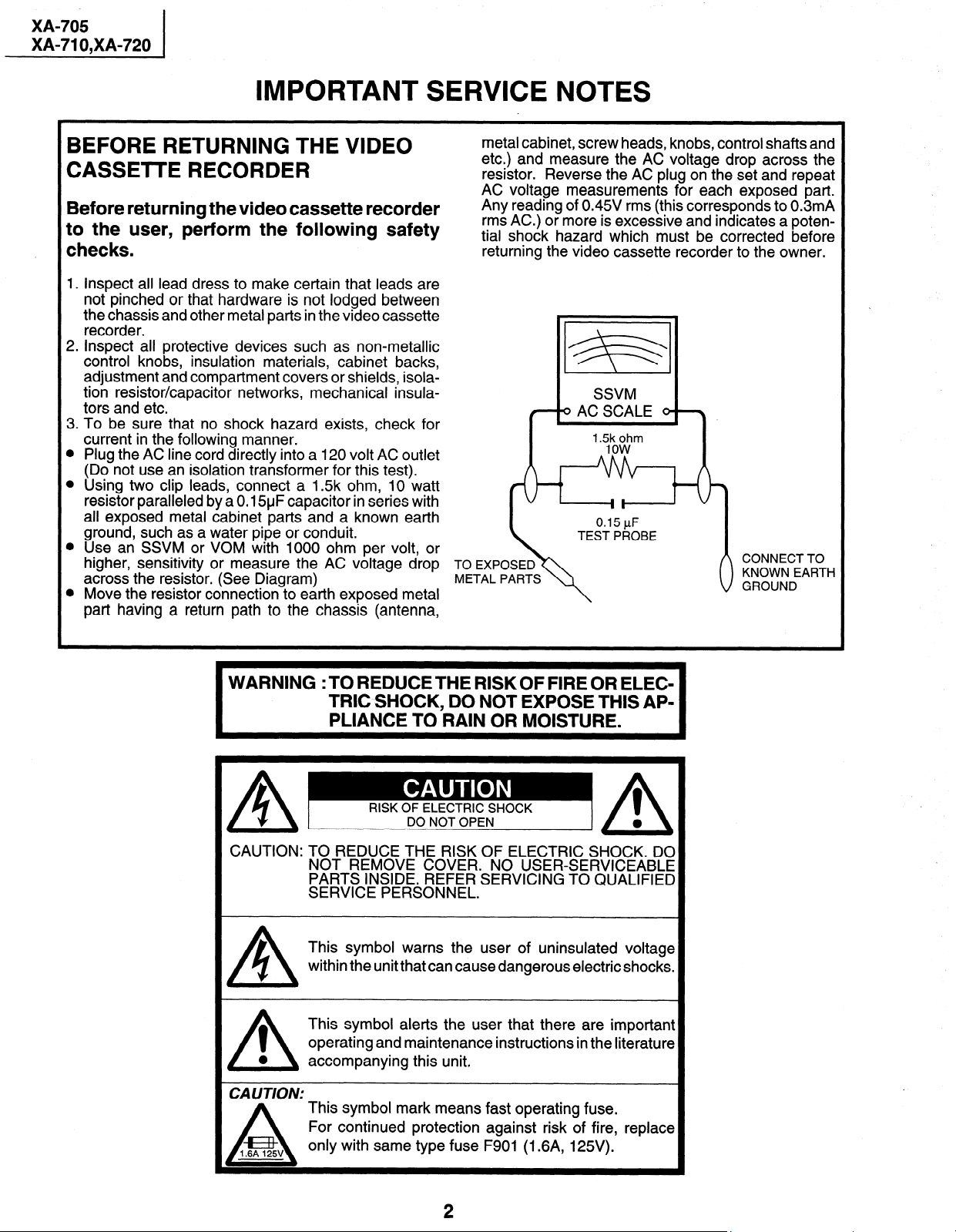
3. To be sure that no shock hazard exists, check for
current in the following manner.
l Plug the AC line cord directly into a 120 volt AC outlet
(Do not use an isolation transformer for this test).
l Using two clip leads, connect a 1.5k ohm, 10 watt
resistor paralleled by a 0.15yF capacitor in series with
all exposed metal cabinet parts and a known earth
ground, such as a water pipe or conduit.
l Use an SSVM or VOM with 1000 ohm per volt, or
higher, sensitivity or measure the AC voltage drop TO EXPOSED
across the resistor. (See Diagram)
l Move the resistor connection to earth exposed metal
part having a return path to the chassis (antenna,
metal cabinet, screw heads, knobs, control shafts and
etc.) and measure the AC voltage drop across the
resistor. Reverse the AC plug on the set and repeat
AC voltaae measurements for each exposed part.
Any readhg of 0.45V rms (this corresponds to 0.3mA
rms AC.) or more is excessive and indicates a potential shock hazard which must be corrected before
returning the video cassette recorder to the owner.
METAL PARTS
SSVM
( 9ACSCALE 9 \
/
’ m%t?m
\
WARNING :TO REDUCETHE RISKOF FIRE OR ELEC-
TRIC SHOCK, DO NOT EXPOSE THIS AP-
PLIANCE TO RAIN OR MOISTURE.
A
RISK OF ELECTRIC SHOCK
A-==-
CAUTION: TO REDUCE THE RISK OF ELECTRIC SHOCK. DO
A
1
0
/\
CAUTION:
1.6A 125v
A
NOT REMOVE COVER. NO USER-SERVICEABLE
PARTS INSIDE. REFER SERVICING TO QUALIFIED
SERVICE PERSONNEL.
This symbol warns the user of uninsulated voltage
within the unit that can cause dangerous electric shocks.
This symbol alerts the user that there are important
operating and maintenance instructions in the literature
accompanying this unit.
This symbol mark means fast operating fuse.
For continued protection against risk of fire, replace
only with same type fuse F901 (1.6A, 125V).
DO NOT OPEN
0
1
0
/\
2
XA-705
XA-71 O,XA-720
PRECAUTIONS IN PART REPLACEMENT
When servicing the unit with power on, be carefwl to the section marked white all over.
This is the primary power circuit which is live.
When checking the soldering side in the tape travel mode, make sure first that the tape has been loaded and then turn
over the PWB with due care to the primary power circuit.
Make readjustment, if needed after replacement of part, with the mechanism and its PWB in position in the main frame.
Start and end sensors: Q701 and Q702
Insert the sensor’s projection deep into the upper hole of the holder. Referring to the PWB, fix the sensors tight
enough.
Photocoupler: IC901
Refer to the symbol on the PWB and the anode marking of the part.
Cam switches A and B: D708 and D709
Adjust the notch of the part to the white marker of the symbol on the PWB. Do not allow any looseness.
Take-up and supply sensors: D707 and D706
Be careful not to confuse the setting direction of the parts in reference to the symbols on the PWB. Do not allow
any looseness.
3
XA-705
XA-71 O,XA-720
1 l GENERAL INFORMATION
l-1 FEATURES
Common Features
0
8 Hours of Recording / Playback (T-160)
0
181 ch Cable Ready With Frequency Synthesizer Tuner
0
CM Skip Search
0
Automatic Playback Function
0
Blue Screen 81 On Screen Setup Programming Function
0
Full Loading System
l
Simple Recording Timer
0
Tamper Proof Function
l
Automatic Tracking System
0
3-Language OSD
0
Sharp Super Picture
0
Instant Replay
l
Universal R/C
0
EZ Set Up
l
Automatic Daylight Saving-Time (DST) Adjustment
e
Quasi S-VHS Playback
l
1 Hour Back-up
1-2 SPECIFICATIONS
1) Recording system
Format:
Luminance Signal:
Chroma Signal:
Color System:
Number of Video Head:
Tape Speed:
2) Video signal
Input Level:
Output Level:
Signal to Noise Ratio:
Horizontal Resolution:
3) Audio signal
Input Level:
Output Level:
Frequency Response:
Signal to Noise Ratio:
Hi-Fi Dynamic Range:
Wow and Flutter:
4) Receiving channel
CATV:
Antenna Input Impedance:
5) Miscellaneous
Fast forward /Rewind Time:
Power Source:
Power Consumption:
Allowable Ambient Temperature:
Operating Humidity:
Dimensions:
Weight:
Accessories Included:
VHS NTSC Standard
FM recording
Low frequency converted direct recording
NTSC
4 PCS.
(SP) 33.35 mm/set
(LP) 16.67 mm/set (playback only)
(EP) 11.12 mm/set
0.5 - 2.0 Vp-p, 75 ohm unbalanced
1 .O Vp-p, 75 ohm unbalanced
45dB Min. (SP mode)
220 lines Min. (SP mode)
- 8 dBs (309 mVrms, 47k ohm Min.)
- 8 dBs (309 mVrms, 1 k ohm Max.)
80Hz - IOkHz (Linear), 20Hz - 20kHz (Hi-Fi) (at SP mode)
43dB (Linear) (at SP mode)
90dB (XA-720)
0.005% max. (XA-720)
VHF:
ch. 2 - 13
UHF:
ch. 14 - 69
ch. A8, A5 - W +84
75 ohm
Approximate 1 minute with T-120 cassette
120 V AC, 60 Hz
20 W at 12OV AC, 60Hz
5 to 40°C (41 to 104°F)
Less than 80% RH
XA-705: 360 (W) x 92 (H) x 269 (D) mm(14-3/16 x 3-5/8 x 10-I 9/32 inch)
XA-710: 360 (W) x 92 (H) x 276 (D) mm(l4-3/16 x 3-5/8 x 1 O-7/8 inch)
XA-720: 360 (W) x 92 (H) x 264 (D) mm(14-3/16 x 3-5/8 x lo-13/32 inch)
2.8 kg (6.0 Ibs)
75 ohm Coaxial Cable, Opetarion Manual, Timer Setting Card,
Infrared R/C Unit, Dry Battery (3 PCS.)
Only for XA-710, XA-720
l Cable Box Control
l Automatic Head Cleaning
l VCR Plus + Programming System
Only for XA-720
l Universal R/C with Light up
l Viewcam Dubbing
Note: Specifications are subject to change without notice.
4
I
X
A0
w” al
D
XX
DD
44
I-
O
c)
P
-I
0
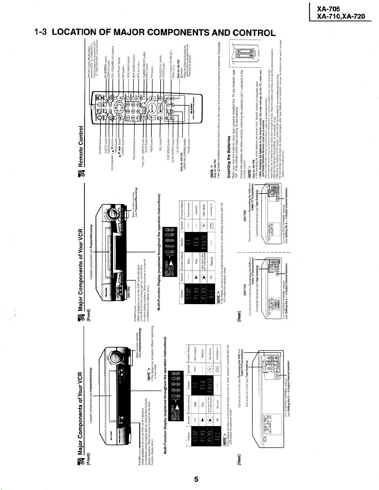
Remote Control Mode Select
buttons (VCR, TV, CABLE/SAT )
l Used to selecl the component (VCR.
Remote Control
a
TV CABLE BOX/SAT ) to be opera!ed
ON SCREEN button
DISPLAY button
VOL (VOLUME) O/O buttons
A/V buttons
CH (CHANNEL)
VCR PLUS+ button
SET button
ZERO BACK button
SKIP SEARCH button
REPLAY button
n controls
:k/Recording)
TAMPER PROOF button
*lOO. ENT /AM/PM button
INPUT button
*FF button
PAUSE/STILL button
*STOP button
TAPE SPEED button
O/O buttons (SLOW @X3.
DPSS &/a,)
AUTO REPEAT button
Only for XA-720
Q button
Only for XA-720
Symbol Function Statu
l Press the button to Illumlna:e the
VIEWCAM DUBBING button
backlll bultons (Indlcatecl with the
*mark) for 10 seconds
_ 1 I
Only for XA-720
If the 0 button IS pressed whrle the backlit buttons are Illumtnated. they WIII remarn illumlnated for an adddtonal 10 seconds
Inserting the Batteries
Make sure that the battenes have been properly Installed first. Fit two batteries type
“AA”. If the remote control stops worktng. fit new batteries.
remote control
INoTE)
On/y for XA-720
l The operating life of the batteries WIII shorten If the “Backlit” function IS frequently used
and Digital Satellite Receiver must be re-entered.
l After changing the batteries in the remote control, the code settings for the TV, cable box
Ensure the battenes are fitted correctly, matching the polarltles (O/e) indicated in the
l uo nor suoject the remote control to shock, water or excessive humidity
l The remote control may not function If the VCR sensor IS In direct sunllght or any other strong light
l Incorrect use of battenes may cause them to leak or burst Read the battery warnings and use the batteries properly
l Do not mix old and new battenes or mix brands 111 use
before re-tnstalling them
l Remove the batterlcs If the remote control wll not be operated for an extended penod of time
_ I‘ AL-^ ____L
- II LII~: relllute control does not function properly when new batteries are Installed. remove the battenes and watt 5 minutes
I
Cable TV Connections)
(XA-720)
Connection terminals (see Tape Dubbing)
Connectron terminals (see Connecting the VCR and
I I I I I I I
I I I I I
3 tf 4 OUTPUT CHANNEL selector 1 (see Setting the 3 +-+ 4 Output Channel Selector)
I
I
a Major Components of Your VCR
[Front]
Cassette compartment (see Playback/Recording)
Cassette compartment (see Playback/Recording)
I
Basic function controls
I
(see Playback/Recording)
on the model
l The design may be slightly different depending
INoTE)
Multi-Function Display (explained throughout the operation instructions)
Multi-Function Display (explained throughout the operation instructions)
Symbol Function Status Display
Display
Display Symbol Function Status
Function Status
Display Symbol
riimir)
Cable TV Connections)
(XA-710)
VCR enters the operation mode
l The display wtll return to the original mode (counter or clock display) 3 seconds after the
Connection terminals (see Tape Dubbitng)
Connection terminals (see Connecting the VCR and
[Rear]
3 tf 4 OUTPUT CHANNEL selector
(see Setting the 3 t+ 4 Output Channel Selector)
I
Cable TV Connections)
Connection terminals (see Tape Dubbing)
Connectlon terminals (see Connecting the VCR and
(see Setting the 3 cf 4 Output Channel Selector)
VCR enters the operation mode
l The display WIII return to the orIgInal mode (counter or clock drsplay) 3 seconds after the
m Major Components of Your VCR
[Front]
POWER button-
(When pressed to turn on the VCR. some lndrcators
on the Multi-Function display light up, and the Multl-Functron
display bnghtens When the power IS turned off, the Multl-
Function dlsplaj dims )
[Rear]
XA-705
XA-71 O,XA-720
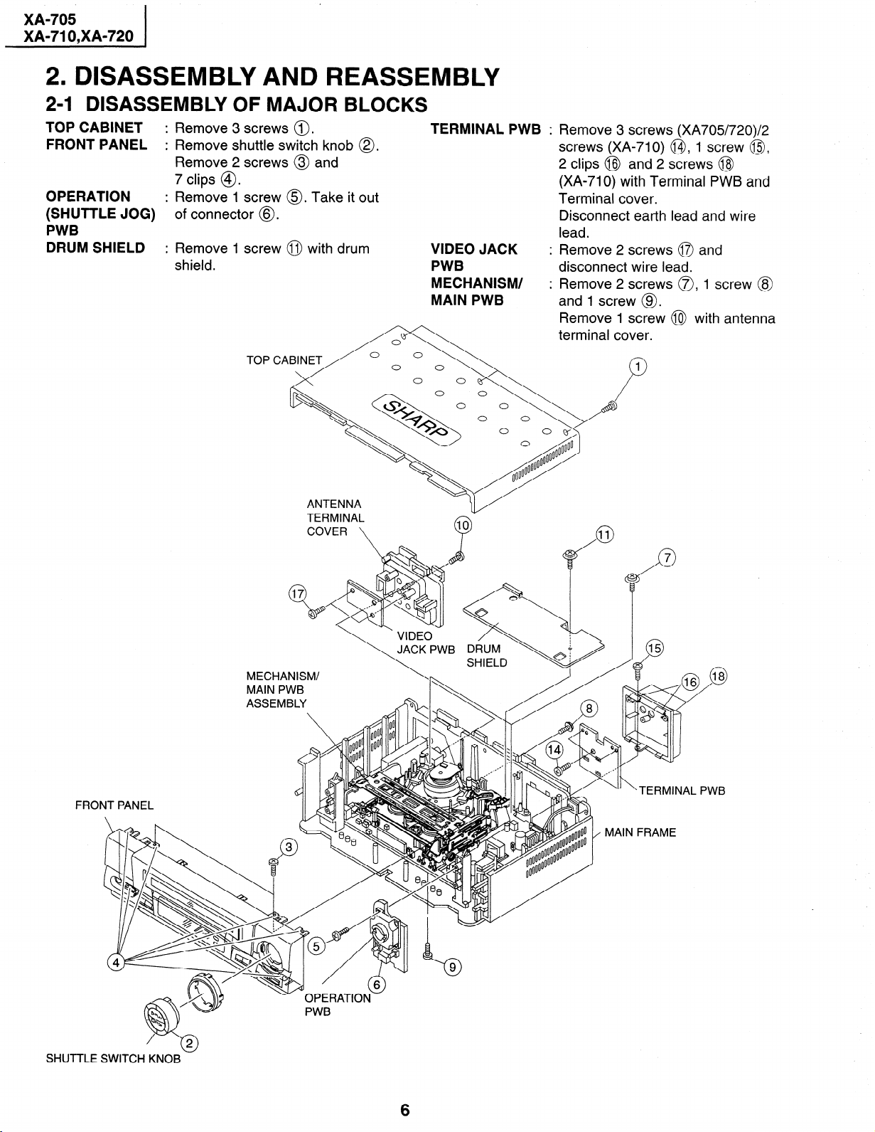
2. DISASSEMBLY AND REASSEMBLY
24 DISASSEMBLY OF MAJOR BLOCKS
TOP CABINET
FRONT PANEL
OPERATION
(SHUTTLE JOG)
PWB
DRUM SHIELD
: Remove 3 screws 0.
: Remove shuttle switch knob 0.
Remove 2 screws @ and
7 clips @.
: Remove 1 screw 0. Take it out
of connector @.
: Remove 1 screw @ with drum
shield.
TERMINAL PWB :
VIDEO JACK
PWB
MECHANISM/
MAIN PWB
Remove 3 screws (XA705/720)/2
screws (XA-710) @I, 1 screw @,
2 clips @J and 2 screws @I
(XA-710) with Terminal PWB and
Terminal cover.
Disconnect earth lead and wire
lead.
Remove 2 screws 0 and
disconnect wire lead.
Remove 2 screws a, 1 screw @
and 1 screw @.
Remove 1 screw @I with antenna
terminal cover.
TOP CABINET
MECHANISM/
:,.
FRO
SHUTTLE
6
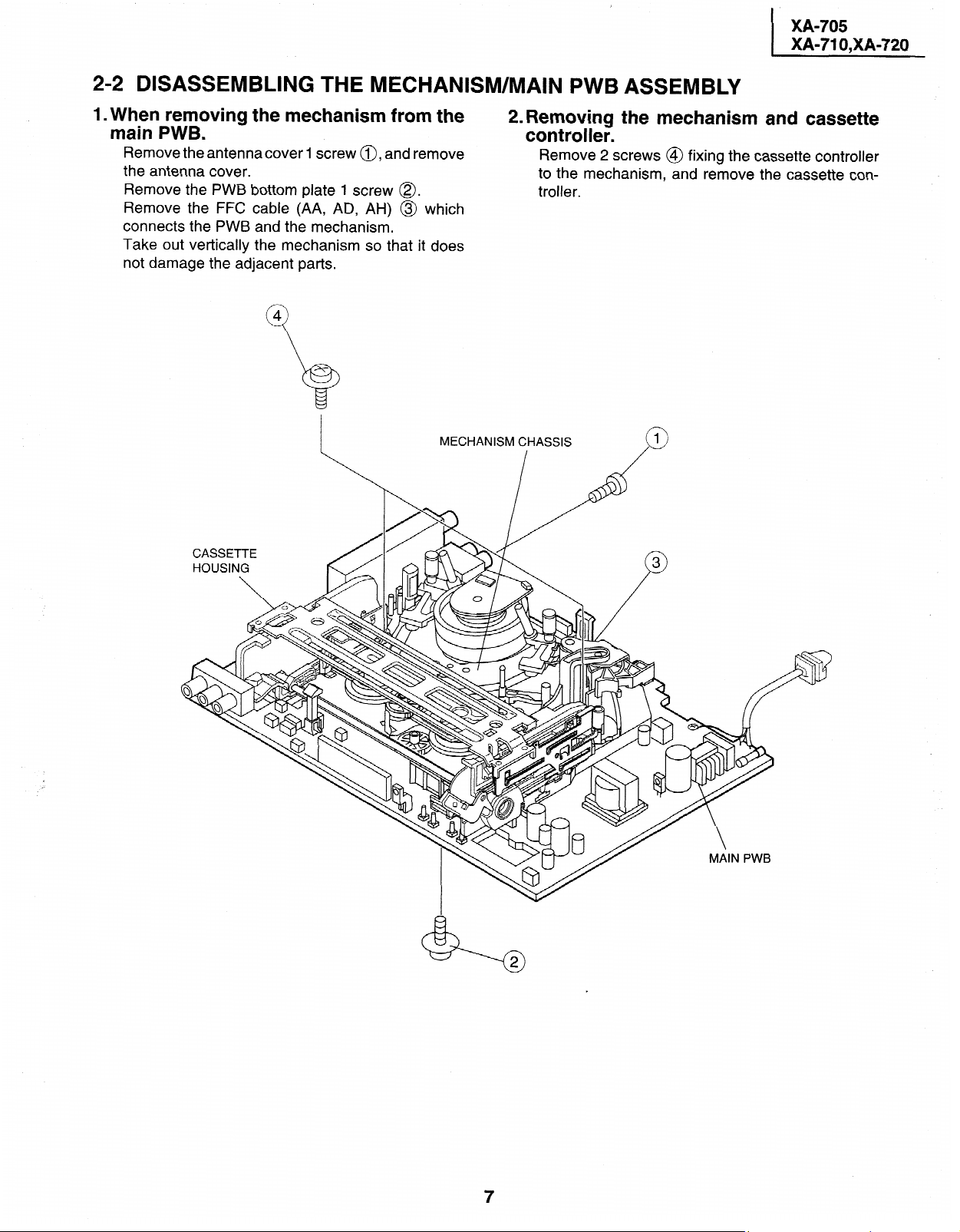
2-2 DISASSEMBLING THE MECHANISM/MAIN PWB ASSEMBLY
1. When removing the mechanism from the main PWB.
Remove the antennacover
the antenna cover.
PWB bottom plate 1 screw @.
Remove
Remove the FFC
connects the PWB and the mechanism.
Take out vertically
not damage the adjacent parts.
the
cable (AA, AD, AH) @ which
the mechanism so
1 screw a, and remove
it does
that
MECHANISM CHASSIS
_I_
2. Removing the mechanism and cassette controller.
Remove 2 screws @
the mechanism, and remove the
to
troller.
fixing the cassette controller
cassette
con-
XA-705
XA-71 O,XA-720
I
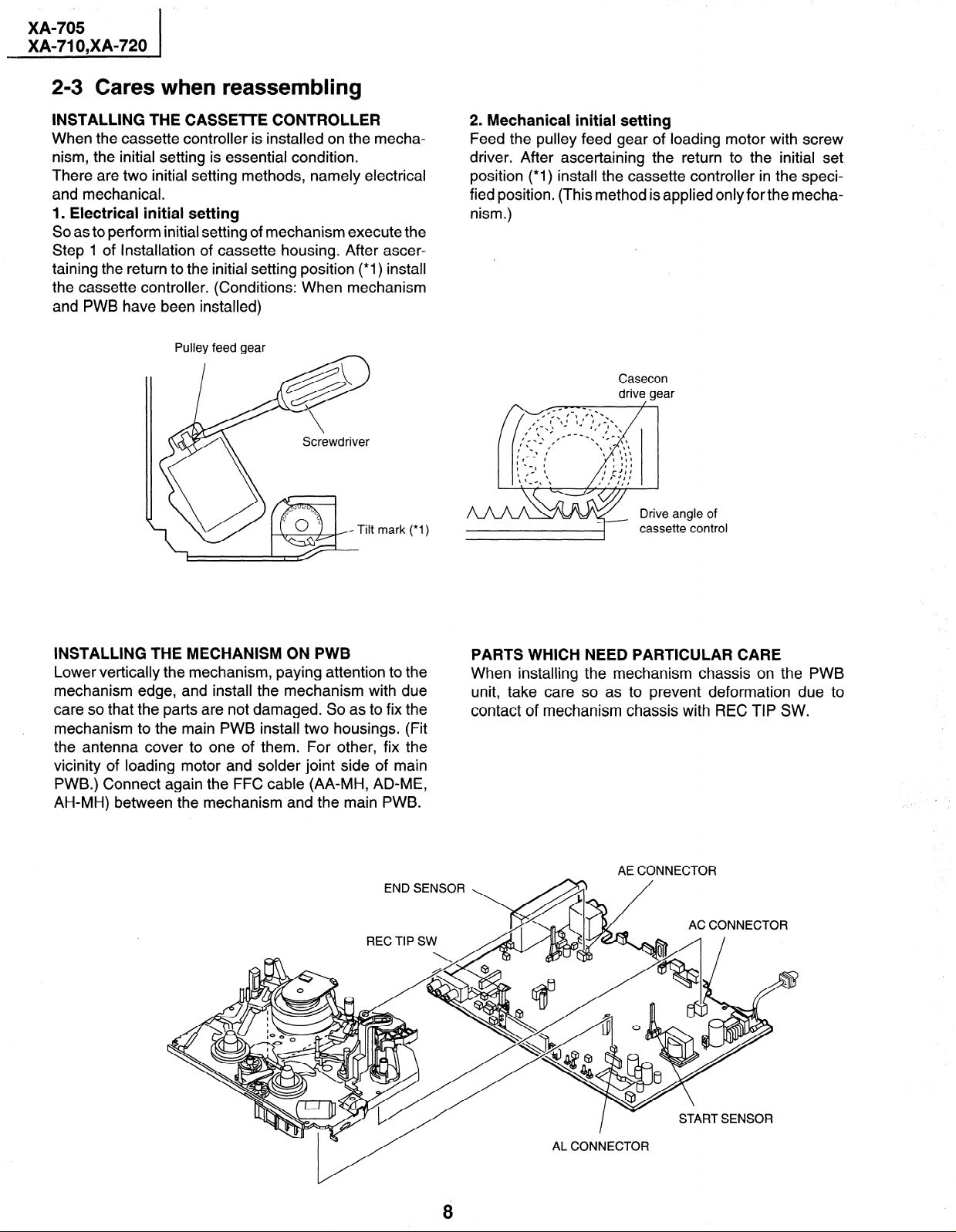
2-3 Cares when reassembling
INSTALLING THE CASSElTE CONTROLLER
When the cassette controller is installed on the mecha-
nism, the initial setting is essential condition.
There are two initial setting methods, namely electrical
and mechanical.
1. Electrical initial setting
So as to perform initial setting of mechanism execute the
Step 1 of Installation of cassette housing. After ascertaining the return to the initial setting position (*I) install
the cassette controller. (Conditions: When mechanism
and PWB have been installed)
Pulley feed gear
mark (*I)
2. Mechanical initial setting
Feed the pulley feed gear of loading motor with screw
driver. After ascertaining the return to the initial set
position (*I) install the cassette controller in the speci-
fied position. (This method is applied only for the mecha-
nism.)
/
Casecon
drive gear
angle of
casse
tte control
INSTALLING THE MECHANISM ON PWB
Lower vertically the mechanism, paying attention to the
mechanism edge, and install the mechanism with due
care so that the parts are not damaged. So as to fix the
mechanism to the main PWB install two housings. (Fit
the antenna cover to one of them. For other, fix the
vicinity of loading motor and solder joint side of main
PWB.) Connect again the FFC cable (AA-MH, AD-ME,
AH-MH) between the mechanism and the main PWB.
END SENSOR
REC TIP SW
PARTS WHICH NEED PARTICULAR CARE
When installing the mechanism chassis on the PWB
unit, take care so as to prevent deformation due to
contact of mechanism chassis with REC TIP SW.
AE CONNECTOR
AC CONNECTOR
8
XA-705
XA-71 O,XA-720
I
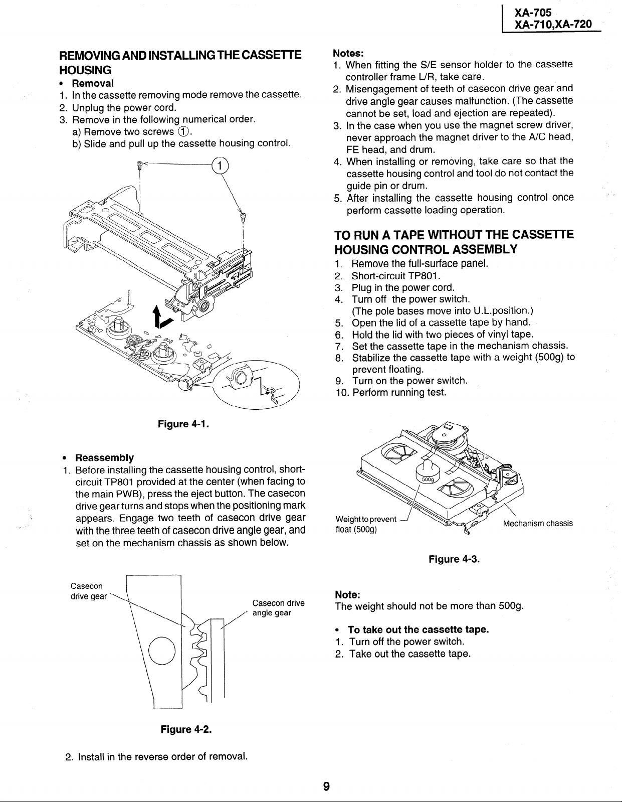
REMOVING AND INSTALLING THE CASSETTE
HOUSING
l Removal
1. In the cassette removing mode remove the cassette.
2. Unplug the power cord.
3. Remove in the following numerical order.
a) Remove two screws 0.
b) Slide and pull up the cassette housing control.
Notes:
1.
When fitting the S/E sensor holder to the cassette
controller frame L/R, take care.
2.
Misengagement of teeth of casecon drive gear and
drive angle gear causes malfunction. (The cassette
cannot be set, load and ejection are repeated).
.
In the case when you use the magnet screw driver,
3
never approach the magnet driver to the A/C head,
FE head, and drum.
4.
When installing or removing, take care so that the
cassette housing control and tool do not contact the
guide pin or drum.
.
After installing the cassette housing control once
5
perform cassette loading operation.
TO RUN A TAPE WITHOUT THE CASSETTE
HOUSING CONTROL ASSEMBLY
1 .
Remove the full-surface panel.
2 .
Short-circuit TP801.
Plug in the power cord.
3
4:
Turn off the power switch.
(The pole bases move into U.L.position.)
5 .
Open the lid of a cassette tape by hand.
Hold the lid with two pieces of vinyl tape.
6
7:
Set the cassette tape in the mechanism chassis.
.
Stabilize the cassette tape with a weight (500g) to
8
prevent floating.
9 . Turn on the power switch.
Perform running test.
10
Figure 4-I.
0 Reassembly
1. Before installing the cassette housing control, shortcircuit TP801 provided at the center (when facing to
the main PWB), press the eject button. The casecon
drive gear turns and stops when the positioning mark
. .
appears. Engage two teeth of casecon drive gear
with the three teeth of casecon drive angle gear, and
set on the mechanism chassis as shown below.
Casecon
Casecon drive
angle gear
-7
/
Weight to prevent
Figure 4-3.
Note:
The weight should not be more than 500g.
0 To take out the cassette tape.
1. Turn off the power switch.
2. Take out the cassette tape.
Mechanism chassis
Figure 4-2.
2. Install in the reverse order of removal.
XA-705
XA-71 O,XA-720
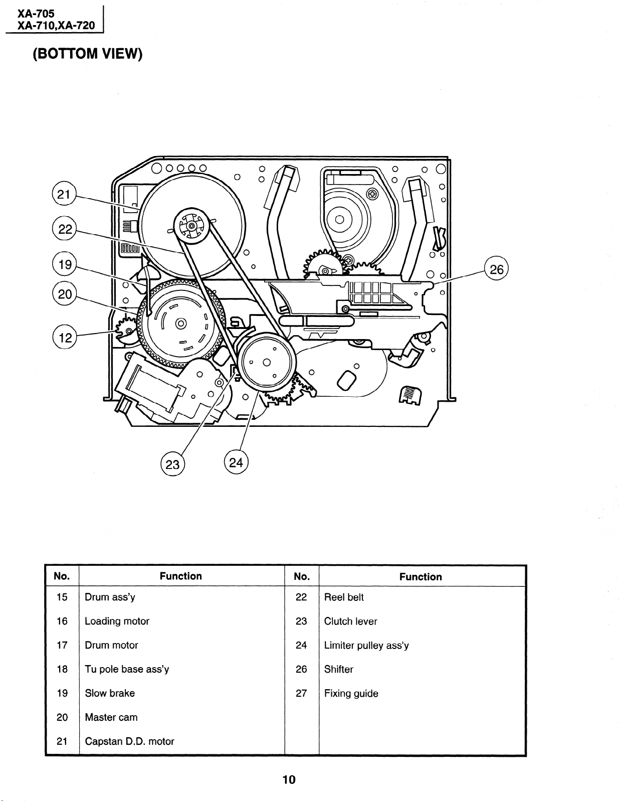
(BOTTOM VIEW)
. Function
No
NO
. Function
15 Drum ass’y 22 Reel belt
16 Loading motor 23 Clutch lever
17 Drum motor 24 Limiter pulley ass’y
18 Tu pole base ass’y 26 Shifter
19 Slow brake 27 Fixing guide
20 Master cam
21 Capstan D.D. motor
10
XA-705
XA-71 O,XA-720
MECHANISM ADJUSTMENT, REPLACEMENT, ASSEM-
4.
BLING AND CLEANING METHODS
The explanation given below relates to the on-site general service (field service) but it does not relates to the adjustment
and replacement which need high-grade equipment, jigs and skill. For example, the drum assembling, replacement and
adjustment service must be performed by the person who have finished the technical courses.
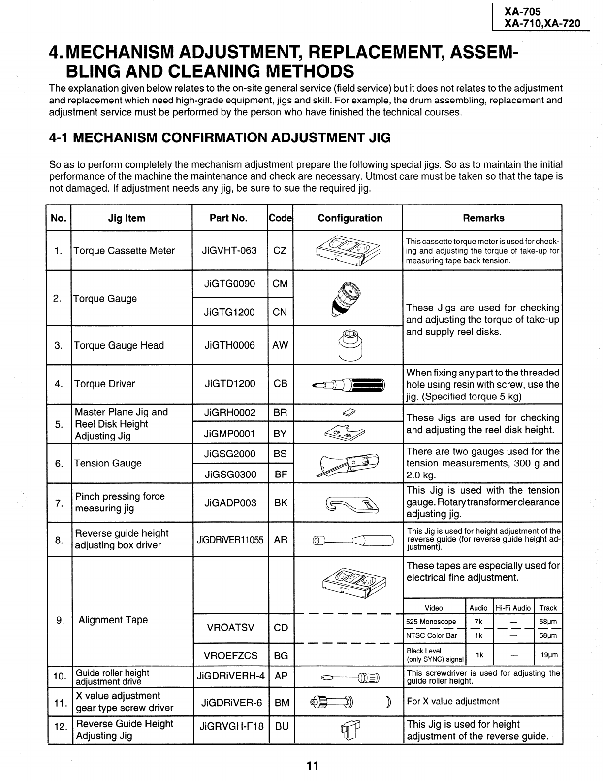
4-l MECHANISM CONFIRMATION ADJUSTMENT JIG
So as to perform completely the mechanism adjustment prepare the following special jigs. So as to maintain the initial
performance of the machine the maintenance and check are necessary. Utmost care must be taken so that the tape is
not damaged. If adjustment needs any jig, be sure to sue the required jig.
.
No
1.
Torque Cassette Meter
Jig Item
Part No.
JiGVHT-063 CZ
Code Configuration
&!5$2@
Remarks
This cassette torque meter is used for checking and adjusting the torque of take-up for
measuring tape back tension.
These Jigs are used for checking
and adjusting the torque of take-up
and supply reel disks.
and adjusting the reel disk height.
transformer clearance
10 Guide roller height
’ adjustment drive
X value adjustment
“*
gear type screw driver
12
Reverse Guide Height
.
Adjusting Jig
JiGDRiVERH-4 AP
JiGDRiVER- BM @------$$
JiGRVGH-F18 BU
11
This screwdriver is used for adjusting the
guide roller height.
For X value adjustment
This Jig is used for height
adjustment of the reverse guide.
XA-705
XA-71 O,XA-720
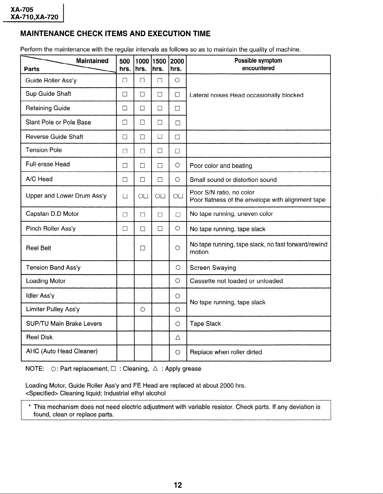
MAINTENANCE CHECK ITEMS AND EXECUTION TIME
Perform the maintenance with the regular intervals as follows so as to maintain the quality of machine.
500 1000 1500 2000
hrs. hrs. hrs. hrs.
Guide Roller Ass’y
Sup Guide Shaft
Retaining Guide cl
cl 0 q
cl
cl
q
q
Cl cl
Slant Pole or Pole Base cl (7 q
Reverse Guide Shaft
Tension Pole
Full-erase Head
A/C Head
Upper and Lower Drum Ass’y
Capstan D.D Motor
Pinch Roller Ass’y 0
cl
q
q
I7 0 q
0
ocl on 00
II 0 0 q
q
0
cl
cl
0
0
0
0
Possible symptom
encountered
0
0
Lateral noises Head occasionally blocked
q
cl
CII
0
Poor color and beating
0
Small sound or distortion sound
Poor S/N ratio, no color
Poor flatness of the envelope with alignment tape
No tape running, uneven color
0
No tape running, tape slack
No tape running, tape slack, no fast forward/rewind
Reel Belt
Tension Band Ass’y
Loading Motor
Idler Ass’y
cl
0
motion
0 Screen Swaying
0
Cassette not loaded or unloaded
0
No tape running, tape slack
Limiter Pulley Ass’y 0
SUP/TU Main Brake Levers 0
0
Tape Slack
Reel Disk /\
AHC (Auto Head Cleaner)
l
NOTE:
0: Part replacement, Cl : Cleaning, n : Apply grease
Replace when roller dirted
0
Loading Motor, Guide Roller Ass’y and FE Head are replaced at about 2000 hrs.
<Specified> Cleaning liquid: Industrial ethyl alcohol
* This mechanism does not need electric adjustment with variable resistor. Check parts. If any deviation is
found, clean or replace parts.
12
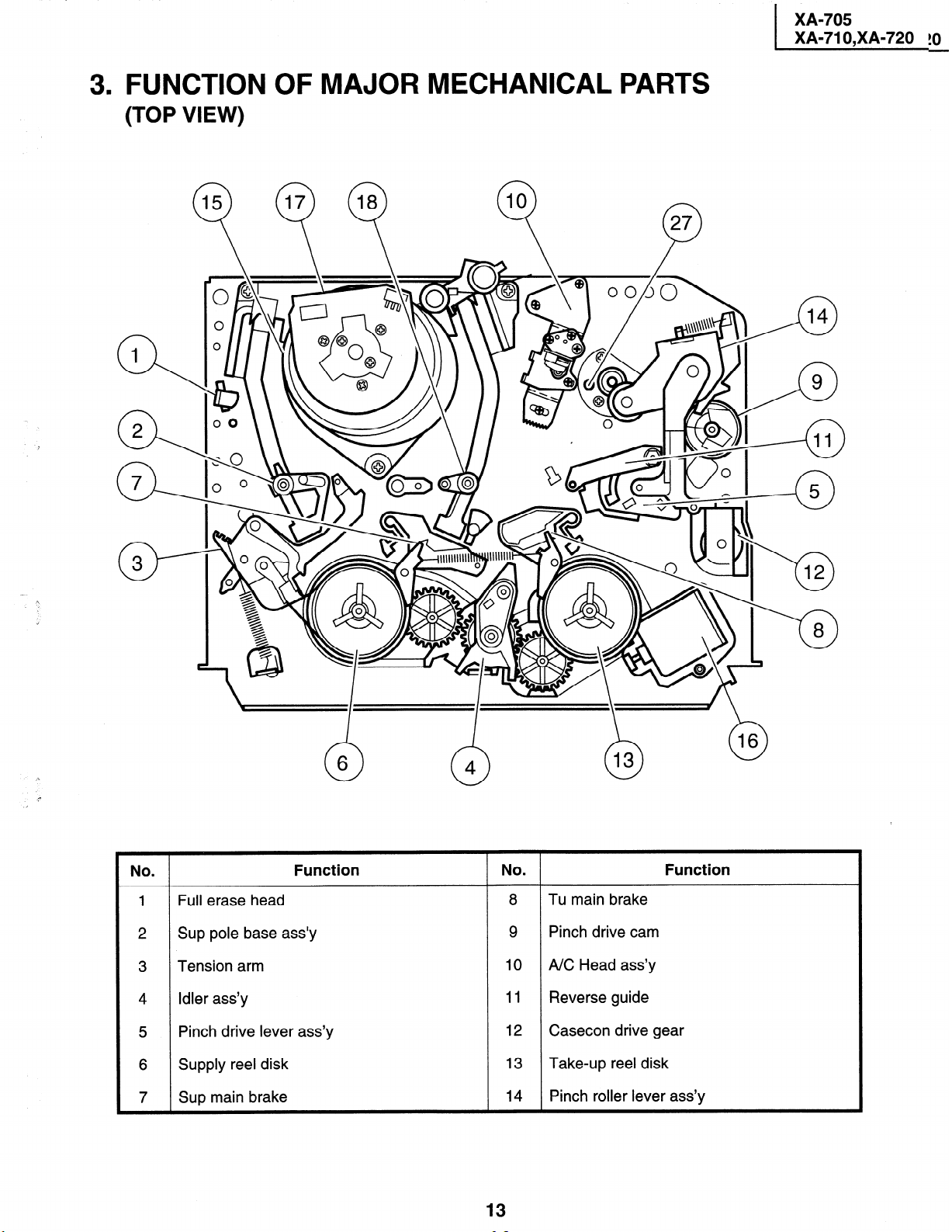
3. FUNCTION OF MAJOR MECHANICAL PARTS
(TOP VIEW)
n 37
XA-705
XA-71 O,XA-720 !O
No
6
0
.
Full erase head
Sup pole base ass’y
Tension arm
Idler ass’y
Pinch drive lever ass’y
Supply reel disk
Sup main brake 14
Function No .
n
4
13
8
Tu main brake
9
Pinch drive cam
10
NC Head ass’y
11
Reverse guide
12
Casecon drive gear
13
Take-up reel disk
Pinch roller lever ass’y
Function
XA-705
r XA-71 O,XA-720
r
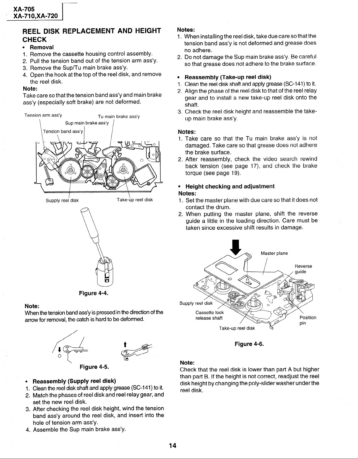
REEL DISK REPLACEMENT AND HEIGHT
CHECK
0
Removal
Remove the cassette housing control assembly.
1.
.
Pull the tension band out of the tension arm ass’y.
2
Remove the Sup/Tu main brake ass’y.
3
4:
Open the hook at the top of the reel disk, and remove
the reel disk.
Note:
Take care so that the tension band ass’y and main brake
ass’y (especially soft brake) are not deformed.
Tension arm ass’y
Sup main brake ass’y
Tension band ass’y
Supply reel’ disk
Tu main brake ass’y
I
Take-hp reel disk
Notes:
1 .
When installing the reel disk, take due care so that the
tension band ass’y is not deformed and grease does
no adhere.
2.
Do not damage the Sup main brake ass’y. Be careful
so that grease does not adhere to the brake surface.
0
Reassembly (Take-up reel disk)
1.
Clean the reel disk shaft and apply grease (SC-141) to it.
. d
2
Align the phase of the reel disk to that of the reel relay
gear and to install a new take-up reel disk onto the
shaft.
3
Check the reel disk height and reassemble the takeup main brake ass’y.
Notes:
I. Take care so that the Tu main brake ass’y is not
damaged. Take care so that grease does not adhere
the brake surface.
2. After reassembly, check the video search rewind
back tension (see page 17) and check the brake
torque (see page 19).
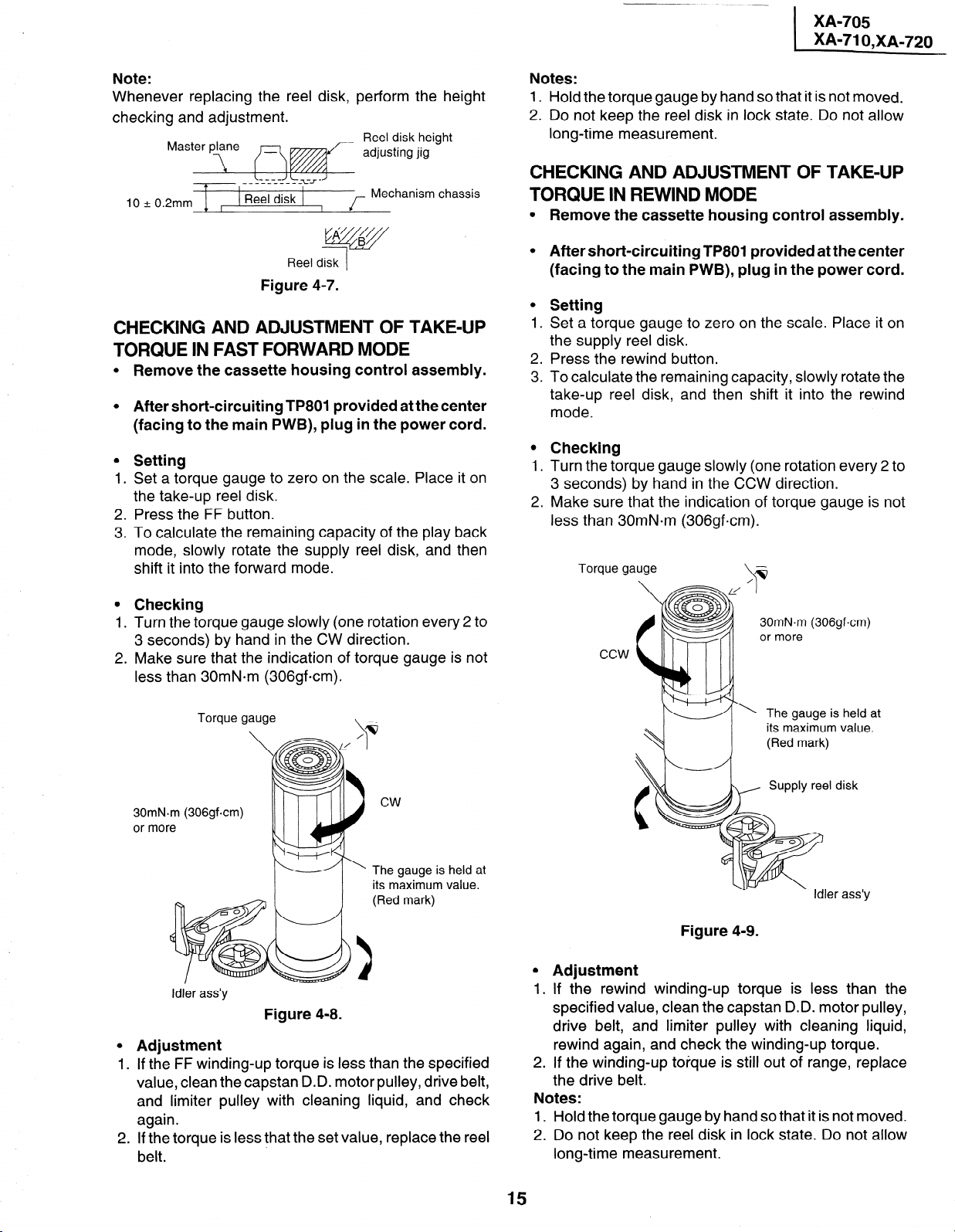
l Height checking and adjustment
Notes:
1.
Set the master plane with due care so that it does not
contact the drum.
2 .
When putting the master plane, shift the reverse
guide a little in the loading direction. Care must be
taken since excessive shift results in damage.
Figure 4-4.
Note:
When the tension band a&y is pressed in the direction of the
arrow for removal, the catch is hard to be deformed.
Figure 4-5.
0
Reassembly (Supply reel disk)
Clean the reel disk shaft and apply grease (SC-141) to it.
1 .
Match the phases of reel disk and reel relay gear, and
2 .
set the new reel disk.
After checking the reel disk height, wind the tension
3 .
band ass’y around the reel disk, and insert into the
hole of tension arm ass’y.
Assemble the Sup main brake ass’y.
4 .
Myter plane
SUPPl
Take-up reel disk
Figure 4-6.
Note:
Check that the reel disk is lower than part A but higher
than part B. If the height is not correct, readjust the reel
disk height by changing the poly-slider washer under the
reel disk.
14
Note:
Whenever replacing the reel disk, perform the height
checking and adjustment.
Reel disk height
adjusting jig
t
10+0.2mm + ,
Reel disk
I f
Mechanism chassis
fjqgy
Reel disk
1
Figure 4-7.
CHECKING AND ADJUSTMENT OF TAKE-UP TORQUE IN FAST FORWARD MODE
0
Remove the cassette housing control assembly.
0
After short-circuiting TP801 provided at the center
(facing to the main PWB), plug in the power cord.
0
Setting
Set a torque gauge to zero on the scale. Place it on
1.
the take-up reel disk.
2.
Press the FF button.
.
To calculate the remaining capacity of the play back
3
mode, slowly rotate the supply reel disk, and then
shift it into the forward mode.
0
Checking
1.
Turn the torque gauge slowly (one rotation every 2 to
3 seconds) by hand in the CW direction.
.
Make sure that the indication of torque gauge is not
2
less than 30mN.m (306gfcm).
Notes:
1. Hold the torque gauge by hand so that it is not moved.
2. Do not keep the reel disk in lock state. Do not allow
long-time measurement.
CHECKING AND ADJUSTMENT OF TAKE-UP
TORQUE IN REWIND MODE
0
Remove the cassette housing control assembly.
0
After short-circuiting TP801 provided at the center
(facing to the main PWB), plug in the power cord.
0
Setting
1.
Set a torque gauge to zero on the scale. Place it on
the supply reel disk.
2.
Press the rewind button.
.
To calculate the remaining capacity, slowly rotate the
3
take-up reel disk, and then shift it into the rewind
mode.
0
Checking
1.
Turn the torque gauge slowly (one rotation every 2 to
3 seconds) by hand in the CCW direction.
2.
Make sure that the indication of torque gauge is not
less than 30mN*m (306gfcm).
Torque gauge
\
30mN.m (306gf-cm)
or more
Torque gauge
30mN-m (306gf.cm)
or more
Idler ass’y
\
cw
The gauge is held at
its maximum value.
(Red mark)
Figure 4-8.
0
Adjustment
I
. . If the FF winding-up torque is less than the specified
value, clean the capstan D.D. motor pulley, drive belt,
and limiter pulley with cleaning liquid, and check
again.
2. If the torque is less that the set value, replace the reel
belt.
-_ The gauge is held at
its maximum value.
(Red mark)
disk
r ass’y
Figure 4-9.
0
Adjustment
1
I . If the rewind winding-up torque is less than the
specified value, clean the capstan D.D. motor pulley,
drive belt, and limiter pulley with cleaning liquid,
rewind again, and check the winding-up torque.
2. If the winding-up torque is still out of range, replace
the drive belt.
Notes:
1. Hold the torque gauge by hand so that it is not moved.
2. Do not keep the reel disk in lock state. Do not allow
long-time measurement.
15
XA-705
XA-71 O,XA-720
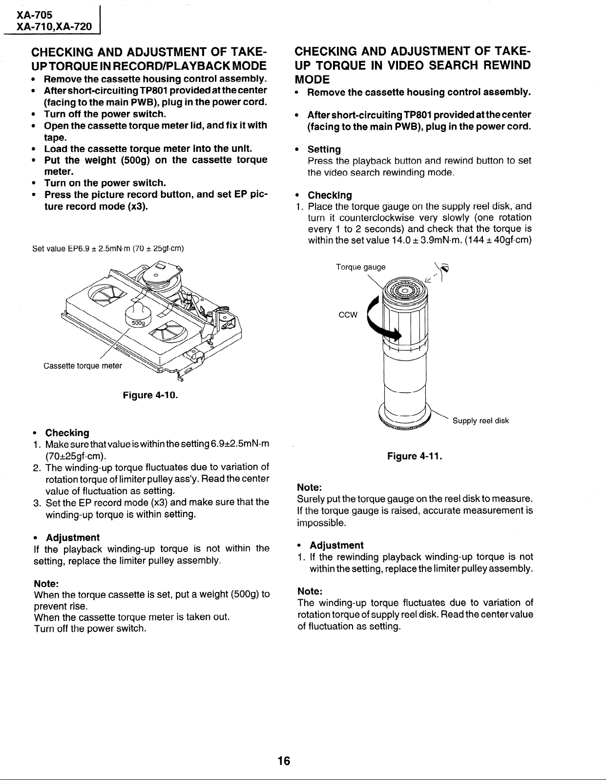
CHECKING AND ADJUSTMENT OF TAKEUPTORQUE IN RECORD/PLAYBACKMODE
Remove the cassette housing control assembly.
After short-circuiting TP801 provided at the center
(facing to the main PWB), plug in the power cord.
Turn off the power switch.
Open the cassette torque meter lid, and fix it with
tape.
Load the cassette torque meter into the unit.
Put the weight (500g) on the cassette torque
meter.
Turn on the power switch.
Press the picture record button, and set EP pic-
ture record mode (x3).
Set value EP6.9 + 2.5mN.m (70 + 25gf-cm)
CHECKING AND ADJUSTMENT OF TAKEUP TORQUE IN VIDEO SEARCH REWIND
MODE
l -Remove the cassette housing control assembly.
l After short-circuiting TP801 provided at the center
(facing to the main PWB), plug in the power cord.
l Setting
Press the playback button and rewind bu
the video search rewinding mode.
l Checking
1. Place the torque gauge on the supply ree
turn it counterclockwise very slowly (one rotation
every 1 to 2 seconds) and check that the torque is
within the set value 14.0 k 3.9mN.m. (144 k 40gfcm)
Torque gauge
*
\
ton to set
disk, and
ccw
Figure 4-l 0.
0
Checking
1 .
Make sure that value is within the setting 6.9+2.5mN.m
(70*25gfcm).
2 .
The winding-up torque fluctuates due to variation of
rotation torque of limiter pulley ass’y. Read the center
value of fluctuation as setting.
.
Set the EP record mode (x3) and make sure that the
3
winding-up torque is within setting.
0
Adjustment
If
the playback winding-up torque is not within the
setting, replace the limiter pulley assembly.
Note:
When the torque cassette is set, put a weight (500g) to
prevent rise.
When the cassette torque meter is taken out.
Turn off the power switch.
\
Supply reel disk
Figure 4-11.
Note:
Surely put the torque gauge on the reel disk to measure.
If the torque gauge is raised, accurate measurement is
impossible.
l Adjustment
1. If the rewinding playback winding-up torque is not
within the setting, replace the limiter pulley assembly.
Note:
The winding-up torque fluctuates due to variation of
rotation torque of supply reel disk. Read the center value
of fluctuation as setting.
16
CHECKING THE VIDEO SEARCH REWIND
I
BACK TENSION
Remove the cassette housing control assembly.
XA-705
XA-71 O,XA-720
After short-circuiting TP801 provided at the center
(facing to the main PWB), plug in the power cord.
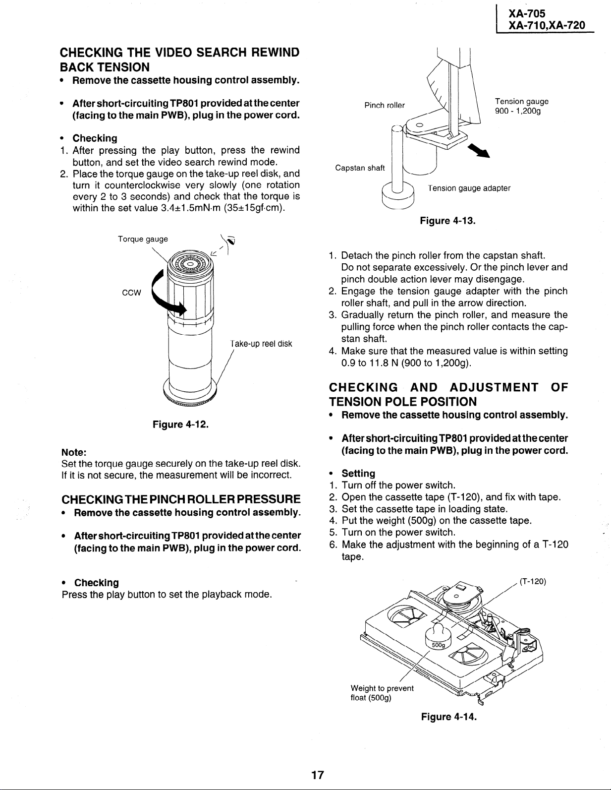
Checking
After pressing the play button, press the rewind
button, and set the video search rewind mode.
Place the torque gauge on the take-up reel disk, and
turn it counterclockwise very slowly (one rotation
every 2 to 3 seconds) and check that the torque is
within the set value 3.4+1.5mN.m (35+15gfcm).
Torque gauge
ccw
Take-up reel disk
/
Figure 4-l 2.
Note:
Set the torque gauge securely on the take-up reel disk.
If it is not secure, the measurement will be incorrect.
CHECKINGTHE PINCH ROLLER PRESSURE
l Remove the cassette housing control assembly.
l After short-circuiting TP801 provided at the center
(facing to the main PWB), plug in the power cord.
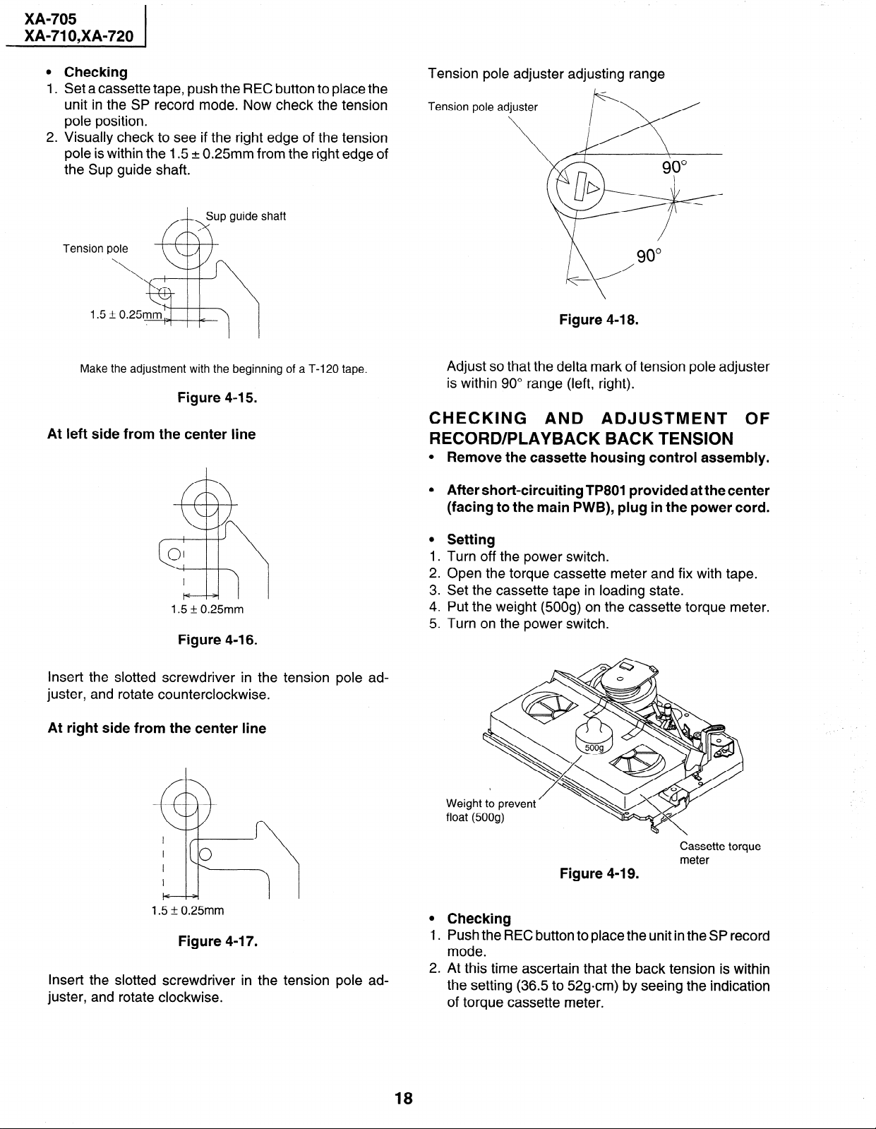
Tension gauge
900 - 1,200g
Capstan shaft
Y
1.
Detach the pinch roller from the capstan shaft.
Do not separate excessively. Or the pinch lever and
pinch double action lever may disengage.
.
2
Engage the tension gauge adapter with the pinch
roller shaft, and pull in the arrow direction.
.
Gradually return the pinch roller, and measure the
3
pulling force when the pinch roller contacts the capstan shaft.
4.
Make sure that the measured value is within setting
0.9 to 11.8 N (900 to 1,200g).
Tension gauge adapter
Figure 4-13.
CHECKING AND ADJUSTMENT OF
TENSION POLE POSITION
l Remove the cassette housing control assembly.
l After short-circuiting TP801 provided at the center
(facing to the main PWB), plug in the power cord.
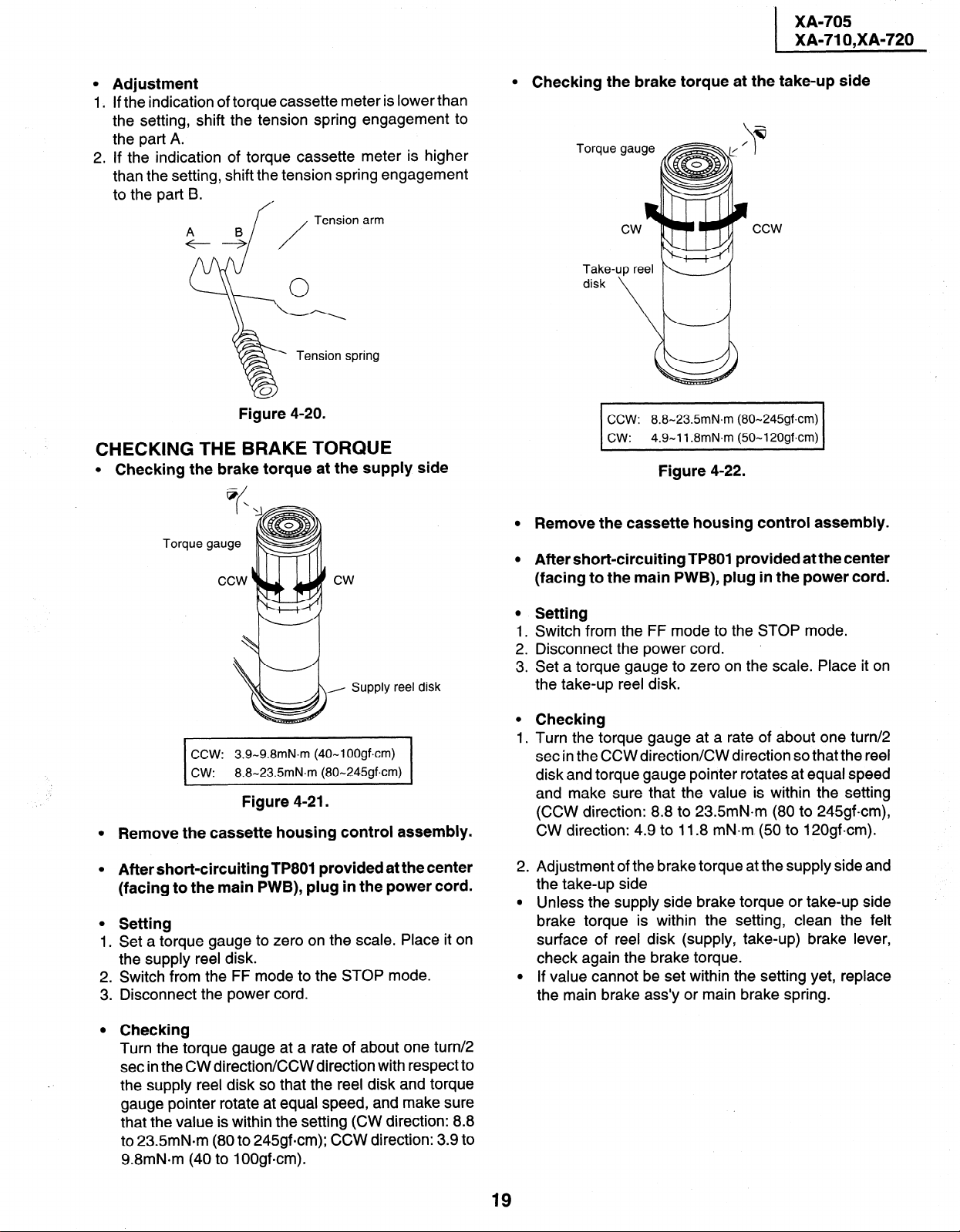
l Setting
1. Turn off the power switch.
2. Open the cassette tape (T-120), and fix with tape.
3. Set the cassette tape in loading state.
4. Put the weight (500s) on the cassette tape.
5. Turn on the power switch.
6. Make the adjustment with the beginning of a T-120
tape.
0 Checking
Press the play button to set the playback mode.
Weight to prevent
float (500s)
Figure 4-l 4.
17
XA-705
XA-71 O,XA-720
0
Checking
1.
Set a cassette
unit in the SP
tape, push the REC button to place the
record mode. Now check the tension
pole position.
2.
Visually check to see if the right edge of the tension
pole is within the 1.5 + 0.25mm from the right edge of
the Sup guide shaft.
Sup guide shaft
A-h
Make the adjustment with the beginning of a T-120 tape.
Figure 4-15.
At left side from the center line
Tension pole adjuster adjusting range
Tension pole
Figure 4-18.
Adjust so that the delta mark of tension pole adjuster
is within 90” range (left, right).
CHECKING AND ADJUSTMENT OF RECORD/PLAYBACK BACK TENSION
0
Remove the cassette housing control assembly.
1.5 * 0.25mm
Figure 4-l 6.
Insert the slotted screwdriver in the tension pole ad-
juster, and rotate counterclockwise.
At right side from the center line
0
After short-circuiting TP801 provided at the center
(facing to the main PWB), plug in the power cord.
0
Setting
1
Turn off the power switch.
2:
Open the torque cassette meter and fix with tape.
3
Set the cassette tape in loading state.
4:
Put the weight (500g) on the cassette torque meter.
.
5
Turn on the power switch.
Weight to prevent
float (500g)
Cassette torque
meter
Figure 4-19.
1.5 k 0.25mm
Figure 4-l 7.
Insert the slotted screwdriver in the tension pole ad-
juster, and rotate clockwise.
18
0
Checking
1.
Push the REC button to place the unit in the SP record
mode.
.
2
At this time ascertain that the back tension is within
the setting (36.5 to 52gcm) by seeing the indication
of torque cassette meter.
l Adjustment
1. If the indication of torque cassette meter is lower than
the setting, shift the tension spring engagement to
the part A.
2. If the indication of torque cassette meter is higher
than the setting, shift the tension spring engagement
to the part 9.
A B
+---+
f
Tension arm
/
Tension spring
XA-705
XA-71 O,XA-720
I
0
Checking the brake torque at the take-up side
Torque
Take-1
up reel K ‘//
disk
Figure 4-20.
CHECKING THE BRAKE TORQUE
0
Checking the brake torque at the supply side
@/
\
I
Torque gauge
Supply reel disk
3.9-9.8mN.m (40-I OOgfxm)
8.8-23.5mN.m (80-245gf.cm)
Figure 4-21.
Remove the cassette housing control assembly.
CCW: 8.8-23.5mN.m (80-245gf.cm)
cw: 4.9-11.8mN.m (50-I 20gf.cm)
Figure 4-22.
0
Remove the cassette housing control assembly.
0
After short-circuiting TP801 provided at the center
(facing to the main PWB), plug in the power cord.
0
Setting
1.
Switch from the FF mode to the STOP mode.
2 .
Disconnect the power cord. .
3 .
Set a torque gauge to zero on the scale. Place it on
the take-up reel disk.
0
Checking
1.
Turn the torque gauge at a rate of about one turn/2
set in the CCW direction/CW direction so that the reel
disk and torque gauge pointer rotates at equal speed
and make sure that the value is within the setting
(CCW direction: 8.8 to 23.5mN.m (80 to 245gfcm),
CW direction: 4.9 to 11.8 mN-m (50 to 120gfcm).
0
After short-circuiting TPSOI provided at the center
(facing to the main PWB), plug in the power cord.
0
Setting
Set a torque gauge to zero on the scale. Place it on
1 .
the supply reel disk.
Switch from the FF mode to the STOP mode.
2 .
Disconnect the power cord.
3 .
0
Checking
Turn the torque gauge at a rate of about one turn/2
set in the CW direction/CCW direction with respect to
the supply reel disk so that the reel disk and torque
gauge pointer rotate at equal speed, and make sure
that the value is within the setting (CW direction: 8.8
to 23.5mN.m (80 to 245gfcm); CCW direction: 3.9 to
9.8mN*m (40 to 1OOgfcm).
2
Adjustment of the brake torque at the supply side and
.
the take-up side
0
Unless the supply side brake torque or take-up side
brake torque is within the setting, clean the felt
surface of reel disk (supply, take-up) brake lever,
check again the brake torque.
0
If value cannot be set within the setting yet, replace
the main brake ass’y or main brake spring.
19
XA-705
XA-71 O,XA-720
REPLACEMENT OF A/C (Audio/Control) HEAD
1. Remove the cassette housing control assembly.
2. In unloading state unplug the power cord.
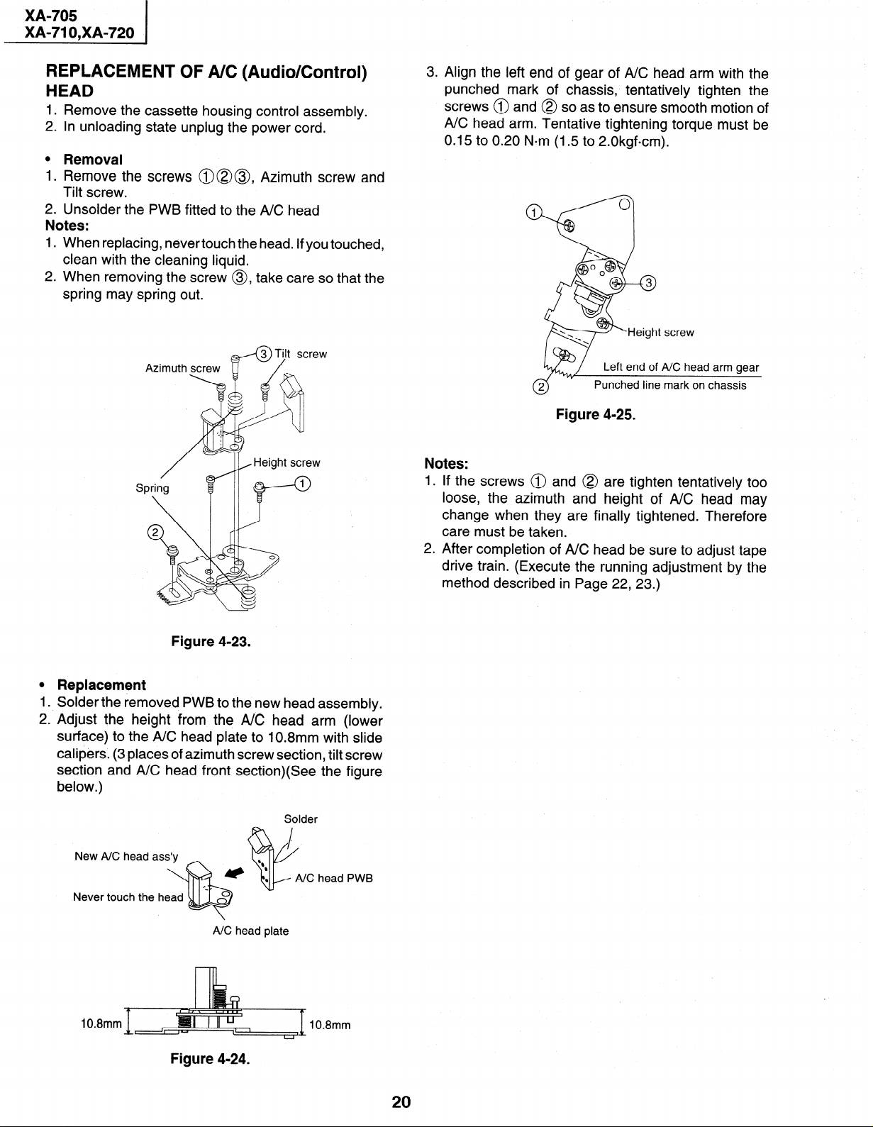
l Removal
1. Remove the screws @@@, Azimuth screw and
Tilt screw.
2. Unsolder the PWB fitted to the A/C head
Notes:
When replacing, never touch the head. If you touched,
1.
clean with the cleaning liquid.
2. When removing the screw 0, take care so that the
spring may spring out.
3. Align the left end of gear of A/C head arm with the
punched mark of chassis, tentatively tighten the
screws @ and @ so as to ensure smooth motion of
A/C head arm. Tentative tightening torque must be
0.15 to 0.20 N*m (1.5 to 2.0kgfcm).
Figure 4-25.
Notes:
1 .
If the screws @ and @
loose, the azimuth and
change when they are finally tightened. Therefore
care must be taken.
2.
After completion of A/C head be sure to adjust tape
drive train. (Execute the running adjustment by the
method described in Page 22, 23.)
are tighten tentatively too
height of A/C head may
Figure 4-23.
0
Replacement
1
Solder the removed PWB to the new head assembly.
2. Adjust the height from the A/C head arm (lower
surface) to the A/C head plate to 10.8mm with slide
calipers. (3 places of azimuth screw section, tilt screw
section and A/C head front section)(See the figure
below.)
Solder
head PWB
Never touch the head
A/C head plate
10.8mm
10.8mm
Figure 4-24.
20
XA-705
I
i XA-71 O,XA-720
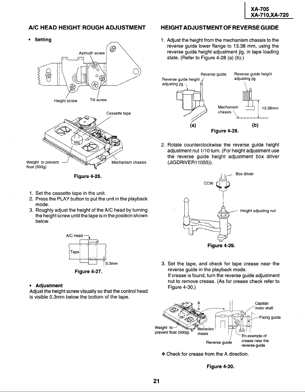
A/C HEAD HEIGHT ROUGH ADJUSTMENT
l Setting
f@ \
Cassette tape
Mechanism chassis
Weight to prevent
float (500g)
/
Height screw
Azimuth screw
Tilt &rew
Figure 4-26.
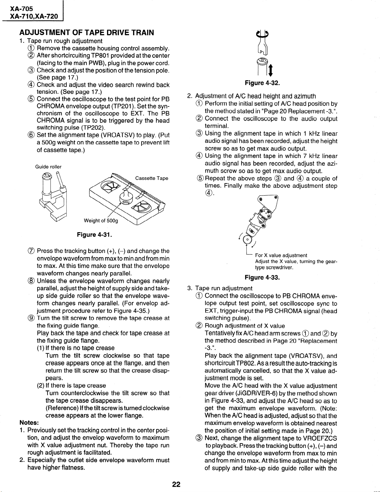
HEIGHTADJUSTMENTOFREVERSEGUIDE
1 Adjust the height from the mechanism chassis to the
reverse guide lower flange to 13.38 mm, using the
reverse guide height adjustment jig, in tape loading
state. (Refer to Figure 4-28 (a) (b).)
Reverse guide height
adjusting jig
\
Reverse guide height J
adjusting jig
Reverse guide
I?
I
Mechanism
chassis
,$
Figure 4-28.
Rotate counterclockwise the reverse guide height
adjustment nut l/l 0 turn. (For height adjustment use
the reverse guide height adjustment box driver
(JiGDRiVER 1055)).
Box driver
ccw
13.38mm
1. Set the cassette tape in the unit.
2. Press the PLAY button to put the unit in the playback
mode.
3. Roughly adjust the height of the A/C head by turning
the height screw until the tape is in the position shown
below.
A/C head 3
.
Figure 4-27.
0 Adjustment
Adjust the height screw visually so that the control head
is visible 0.3mm below the bottom of the tape.
Height adjusting nut
Figure 4-29.
u. Set the tape, and check for tape crease near the
reverse guide in the playback mode.
If crease is found, turn the reverse guide adjustment
nut to remove crease. (As for crease check refer to
Figure 4-30.)
Capstan
/‘motor shaft
Jide
Reverse guid;
L- En example of
I
crease near the
reverse guide
Fixing gi
* Check for crease
21
from the A direction.
Figure 4-30.
XA-705
XA-71 O,XA-720
ADJUSTMENT
1. Tape run rough
Remove the
OF TAPE DRIVE TRAIN
adjustment
cassette housing control assembly.
After shortcircuiting TP801 provided at the center
(facing to the main PWB), plug in the power cord.
Check and adjust the position of the tension pole.
(See page 17.)
Check and adjust the video search rewind back
tension. (See page 17.)
Connect the oscilloscope to the test point for PB
CHROMA envelope output (TP201). Set the synchronism of the oscilloscope to EXT. The PB
CHROMA signal is to be triggered by the head
switching pulse (TP202).
Set the alignment tape (VROATSV) to play. (Put
a 500g weight on the cassette tape to prevent lift
of cassette tape.)
Guide roller
Figure 4-32.
2. Adjustment of A/C head height and azimuth
@ Perform the initial setting of A/C head position by
the method stated in “Page 20 Replacement -3.“.
@ Connect the oscilloscope to the audio output
terminal.
@ Using the alignment tape in which 1 kHz linear
audio signal has been recorded, adjust the height
screw so as to get max audio output.
@ Using the alignment tape in which 7 kHz linear
audio signal has been recorded, adjust the azimuth screw so as to get max audio output.
@Repeat the above steps @ and @ a couple of
times. Finally make the above adjustment step
.
@I
@ Bp
c-7
Figure 4-31.
Press the tracking button (+), (-) and change the
envelope waveform from max to min and from min
to max. At this time make sure that the envelope
waveform changes nearly parallel.
Unless the envelope waveform changes nearly
parallel, adjust the height of supply side and takeup side guide roller so that the envelope waveform changes nearly parallel. (For envelop ad-
justment procedure refer to Figure 4-35.)
Turn the tilt screw to remove the tape crease at
the fixing guide flange. ,
Play back the tape and check for tape crease at
the fixing guide flange.
(1) If there is no tape crease
Turn the tilt screw clockwise so that tape
crease appears once at the flange, and then
return the tilt screw so that the crease disappears.
(2) If there is tape crease
Turn counterclockwise the tilt screw so that
the tape crease disappears.
(Reference) If the tilt screw is turned clockwise
crease appears at the lower flange.
Previously set the tracking control in the center position, and adjust the envelop waveform to maximum
with X value adjustment nut. Thereby the tape run
rough adjustment is facilitated.
Especially the outlet side envelope waveform must
have higher flatness.
I- For X value adjustment
Adjust the X value, turning the geartype screwdriver.
Figure 4-33.
3. Tape run adjustment
Connect the oscilloscope to PB CHROMA envelope output test point, set oscilloscope sync to
EXT, trigger-input the PB CHROMA signal (head
switching pulse).
Rough adjustment of X value
Tentatively fixA/C head arm screws @ and @ by
the method described in Page 20 “Replacement
II
-3
Play back the alignment tape (VROATSV), and
shortcircuit TP802. As a result the auto-tracking is
automatically cancelled, so that the X value adjustment mode is set.
Move the A/C head with the X value adjustment
gear driver (JiGDRiVER-6) by the method shown
in Figure 4-33, and adjust the A/C head so as to
get the maximum envelope waveform. (Note:
When the A/C head is adjusted, adjust so that the
maximum envelop waveform is obtained nearest
the position of initial setting made in Page 20.)
@ Next, change the alignment tape to VROEFZCS
to playback. Press the tracking button (+), (-) and
change the envelope waveform from max to min
and from min to max. At this time adjust the height
of supply and take-up side guide roller with the
22
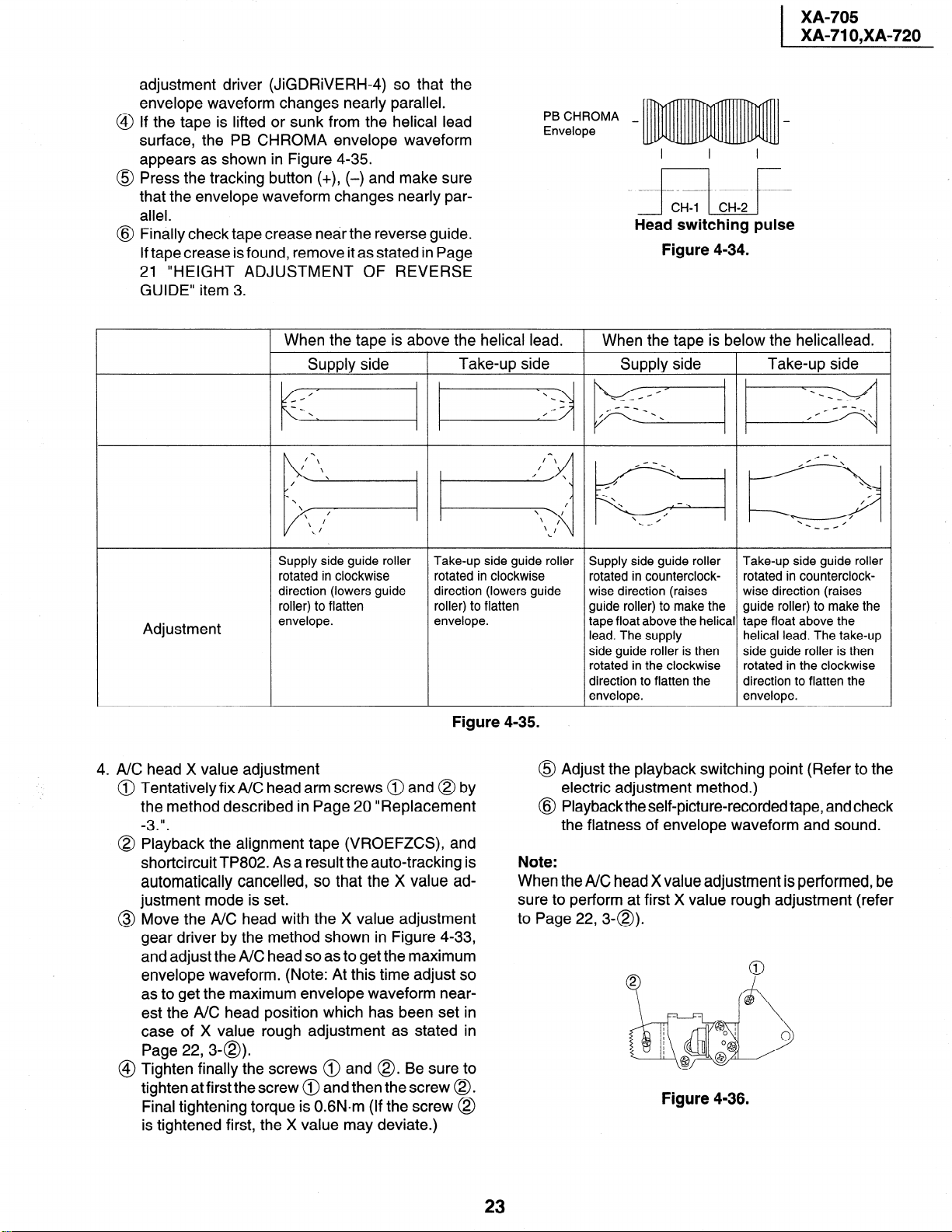
adjustment driver (JiGDRiVERH-4) so that the
envelope waveform changes nearly parallel.
If the tape is lifted or sunk from the helical lead
surface, the PB CHROMA envelope waveform
appears as shown in Figure 4-35.
Press the tracking button (+), (-) and make sure
that the envelope waveform changes nearly parallel.
Finally check tape crease near the reverse guide.
If tape crease is found, remove it as stated in Page
21 “HEIGHT ADJUSTMENT OF REVERSE
GUIDE” item 3.
XA-705
XA-71 O,XA-720
PB CHROMA _
Envelope
Head switching pulse
Figure 4-34.
When the tape is above the helical lead.
I-
Supply side
Supply side guide roller
rotated in clockwise
direction (lowers guide
roller) to flatten
Adjustment
envelope.
4. A/C head X value adjustment
Tentatively fix A/C head arm screws @ and @ by
the method described in Page 20 “Replacement
II
-3
Playback the alignment tape (VROEFZCS), and
shortcircuit TP802. As a result the auto-tracking is
automatically cancelled, so that the X value adjustment mode is set.
Move the A/C head with the X value adjustment
gear driver by the method shown in Figure 4-33,
and adjust the A/C head so as to get the maximum
envelope waveform. (Note: At this time adjust so
as to get the maximum envelope waveform nearest the A/C head position which has been set in
case of X value rough adjustment as stated in
Page 22,3-a).
Tighten finally the screws @ and 0. Be sure to
tighten at firstthe screw @ and then the screw 0.
Final tightening torque is 0.6N.m (If the screw @
is tightened first, the X value may deviate.)
Take-up side
i:i”
Take-up side guide roller
rotated in clockwise
direction (lowers guide
roller) to flatten
envelope.
Figure 4-35.
0
@
Note:
When the A/C head X value adjustment is performed, be
sure to perform at first X value rough adjustment (refer
to Page 22,3-Q).
When the tape is below the helicallead.
Supply side
Take-up side
pq
\
\
\
.
/
/
\
Supply side guide roller Take-up side guide roller
rotated in counterclock- rotated in counterclock-
wise direction (raises wise direction (raises
guide roller) to make the guide roller) to make the
tape float above the helical tape float above the
lead. The supply helical lead. The take-up
side guide roller is then
rotated in the clockwise rotated in the clockwise
direction to flatten the direction to flatten the
envelope. envelope.
side guide roller is then
-_H
/
0
Adjust the playback switching point (Refer to the
electric adjustment method.)
Playback the self-picture-recorded tape, and check
the flatness of envelope waveform and sound.
Figure 4-36.
23
XA-705
XA-71 O,XA-720
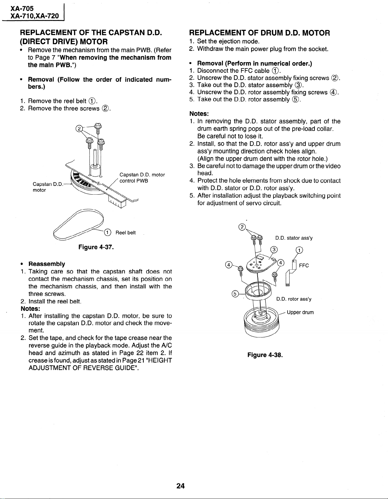
REPLACEMENT OF THE CAPSTAN D.D.
(DIRECT DRIVE) MOTOR
l Remove the mechanism from the main PWB. (Refer
to Page 7 “When removing the mechanism from
the main PWB.“)
l Removal (Follow the order of indicated num-
bers.)
1. Remove the reel belt 0.
2. Remove the three screws @.
motor
Capstan D.D.
motor
REPLACEMENT OF DRUM D.D. MOTOR
1 .
Set the ejection mode.
2 .
Withdraw the main power plug from the socket.
0
Removal (Perform in numerical order.)
1 .
Disconnect the FFC cable 0.
2 .
Unscrew the D.D. stator assembly fixing screws 0.
3
Take out the D.D. stator assembly 0.
4:
Unscrew the D.D. rotor assembly fixing screws @.
.
5
Take out the D.D. rotor assembly 0.
Notes:
1.
In removing the D.D. stator assembly, part of the
drum earth spring pops out of the pre-load collar.
Be careful not to lose it.
2
Install, so that the D.D. rotor ass’y and upper drum
ass’y mounting direction check holes align.
(Align the upper drum dent with the rotor hole.)
.
3
Be careful not to damage the upper drum or the video
head.
4.
Protect the hole elements from shock due to contact
with D.D. stator or D.D. rotor ass’y.
5.
After installation adjust the playback switching point
for adjustment of servo circuit.
Reel belt
Figure 4-37.
0
Reassembly
1
.
Taking care so that the capstan shaft does not
contact the mechanism chassis, set its position on
the mechanism chassis, and then install with the
three screws.
2. Install the reel belt.
Notes:
1. After installing the capstan D.D. motor, be sure to
rotate the capstan D.D. motor and check the movement.
2. Set the tape, and check for the tape crease near the
reverse guide in the playback mode. Adjust the A/C
head and azimuth as stated in Page 22 item 2. If
crease is found, adjust as stated in Page 21 “HEIGHT
ADJUSTMENT OF REVERSE GUIDE”.
D.D. stator ass’y
1
P
FFC
1. rotor ass’y
Upper drum
Figure 4-38.
24
,
XA-705
XA-71 O,XA-720
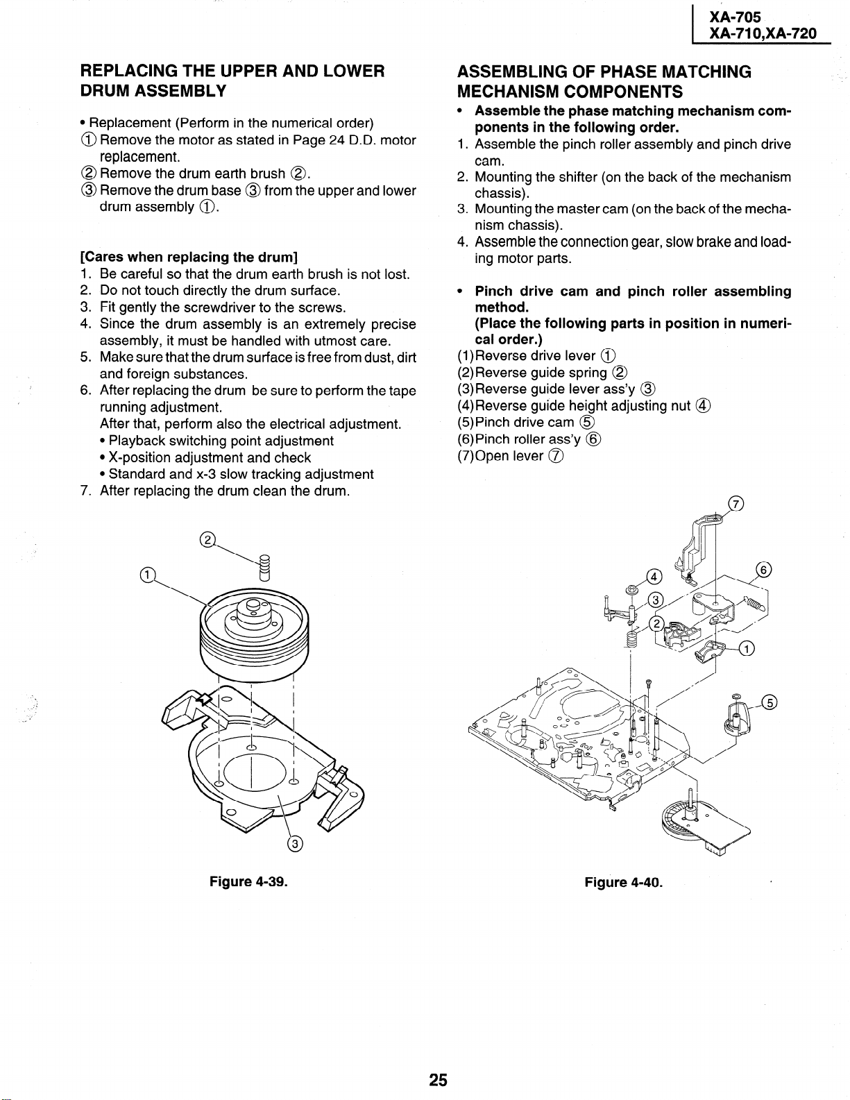
REPLACING THE UPPER AND LOWER DRUM ASSEMBLY
l Replacement (Perform in the numerical order)
@ Remove the motor as stated in Page 24 D.D. motor
replacement.
@ Remove the drum earth brush 8.
Remove the dru
0
drum assembly 0 .
[Cares when replacing the drum]
1.
Be careful so that the drum earth brush is not lost.
2 .
Do not touch directly the drum surface.
3
Fit gently the screwdriver to the screws.
4:
Since the drum assembly is an extremely precise
assembly, it must be handled with utmost care.
.
5
Make sure that the drum surface is free from dust, dirt
1
I
and foreign substances.
.
After replacing the drum be sure to perform the tape
6
running adjustment.
After that, perform also the electrical adjustment.
l Playback switching point adjustment
l X-position adjustment and check
l Standard and x-3 slow tracking adjustment
7.
After replacing the drum clean the drum.
m base
@ from the
upper
and lower
ASSEMBLING OF PHASE MATCHING MECHANISM COMPONENTS
0
Assemble the phase matching mechanism components in the following order.
1 .
Assemble the pinch roller assembly and pinch drive
cam.
2.
Mounting the shifter (on the back of the mechanism
chassis).
3 .
Mounting the master cam (on the back of the mechanism chassis).
4.
Assemble the connection gear, slow brake and load-
ing motor parts.
0
Pinch drive cam and pinch roller assembling
method.
(Place the following parts in position in numerical order.)
(l)Reverse drive lever @
(2)Reverse guide spring @
(3)Reverse guide lever ass’y @
(4)Reverse guide height adjusting nut @
(5)Pinch drive cam @
(6)Pinch roller ass’y @
(7)Open lever 0
Figure 4-39.
Figure 4-40.
25
XA-705
XA-71 O,XA-720
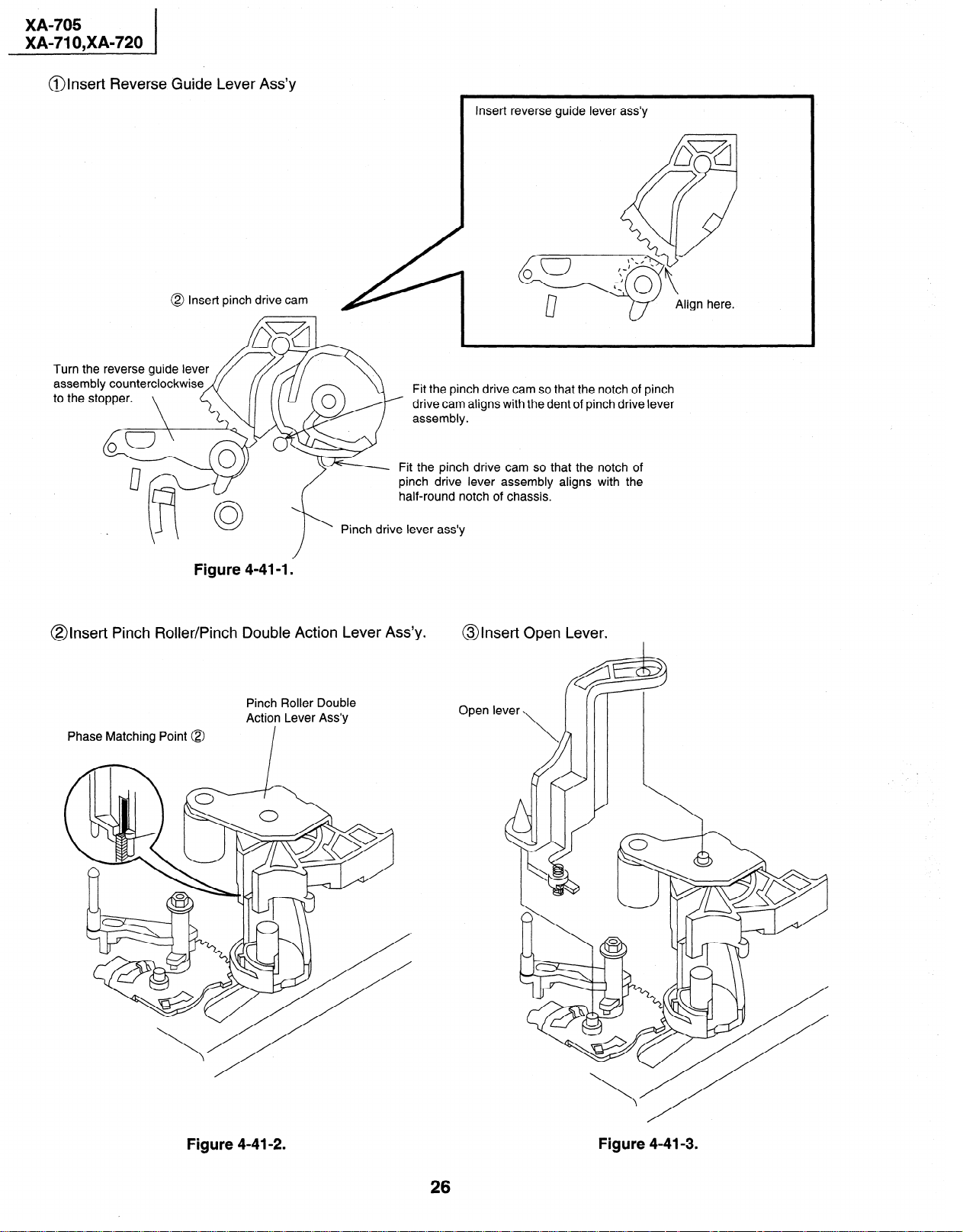
@Insert Reverse Guide Lever Ass’y
@ Insert pinch drive cam
Insert reverse guide lever
Fit the pinch drive cam so that the notch of pinch
drive cam aligns with the dent of pinch drive lever
- Fit the pinch drive cam so that the notch of
pinch drive lever assembly aligns with the
half-round notch of chassis.
ass’y
Pinch drive lever ass’y
Figure 4-41-l.
@Insert Pinch Roller/Pinch Double Action Lever Ass’y.
Pinch Roller Double
Action Lever Ass’y
Phase Matching Point @
@Insert Open Lever.
G3
Open lever
\
R@
Figure 4-41-2.
Figure 4-41-3.
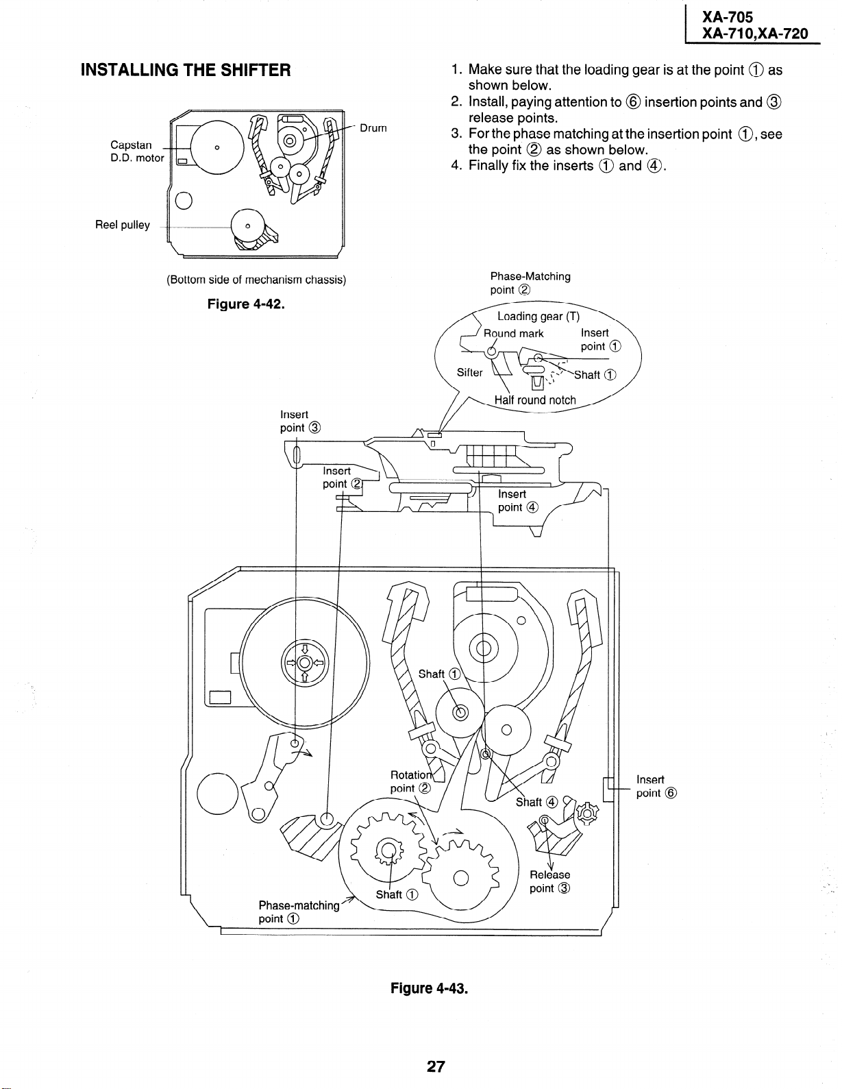
INSTALLING THE SHIFTER
._
Capstan
D.D. moto
Reel pulley
Drum
/ iK&w*o
1.
Make sure that the loading gear is at the point @ as
shown below.
2.
Install, paying attention to @ insertion points and @
release points.
.
3
For the phase matching at the insertion point 0, see
the point @ as shown below.
4.
Finally fix the inserts @ and @.
(Bottom side of mechanism chassis)
Figure 4-42.
Insert
point @
Phase-Matching
point @
notch
-/Y I
/ \ / -I
Rotatior)(\l /
Figure 4-43.
27
Insert
- point @
Loading...