

Page 1

WQ-790W
SERVICE MANUAL
No. S7852WQ790W//
WQ-790W
• In the interests of user-safety the set should be restored to its original
condition and only parts identical to those specified should be used.
CONTENTS
Page
SPECIFICATIONS ...............................................................................................................................................................1
VOLTAGE SELECTION.......................................................................................................................................................2
AC POWER SUPPLY CORD AND PLUG ........................................................................................................................... 2
FITTING OF DIAL POINTER ...............................................................................................................................................2
NAMES OF PARTS ............................................................................................................................................................. 3
DISASSEMBLY....................................................................................................................................................................4
ADJUSTMENT .....................................................................................................................................................................5
NOTES ON SCHEMATIC DIAGRAM .................................................................................................................................. 6
VOLTAGE ............................................................................................................................................................................7
TYPES OF TRANSISTOR AND LED...................................................................................................................................7
SCHEMATIC DIAGRAM / WIRING SIDE OF P.W.BOARD................................................................................................. 8
PARTS GUIDE / EXPLODED VIEW
SPECIFICATIONS
● General
Power source: AC 110-127 V/220-240 V,
50/60 Hz
DC 15 V ["D" size (UM/SUM1, R20 or HP-2) battery × 10]
Power consumption: 20 W
Output power: PMPO; 120 W (60 W + 60 W)
(AC operation)
MPO (Max.); 30 W
(15 W + 15 W) (AC operation)
RMS; 15 W (7.5 W + 7.5 W)
(DC operation, 10 % T.H.D.)
Speakers: 12 cm (4-3/4") free-edge
speaker × 2
5 cm (2") surround speaker × 2
Input terminal: MIC 1/2; 1 mV/600 ohms
CD/LINE; 350 mV/47 kohms
Output terminal: Headphones; 16-50 ohms
(recommended; 32 ohms)
Dimensions: Width; 630 mm (24-13/16")
Height; 205 mm (8-1/8")
Depth; 215 mm (8-1/2")
Weight: 5.3 kg (11.7 lbs.) without bat-
teries
SHARP CORPORATION
● Radio section
Frequency range: FM; 88 - 108 MHz
SW1; 2.3 - 7.3 MHz
SW2; 7.3 - 22 MHz
MW; 526.5 - 1,606.5 kHz
● Tape recorder section
Frequency response: 60 - 12,000 Hz (Normal tape)
Signal/noise ratio: 40 dB (TAPE 1, recording/playback)
55 dB (TAPE 2, playback)
Wow and flutter: 0.15 % (WRMS)
Motor: DC 15 V electric governor
Bias system: AC bias
Erase system: Magnet erase
Specifications for this model are subject to change without
prior notice.
This document has been published to be used
for after sales service only.
The contents are subject to change without notice.
Page 2
WQ-790W
FOR A COMPLETE DESCRIPTION OF THE OPERATION OF THIS UNIT, PLEASE REFER
TO THE OPERATION MANUAL.
VOLTAGE SELECTION
Before operating the unit on mains, check the preset voltage. If the voltage is different from your local voltage, adjust the voltage
as follows: Slide the AC power supply socket to the visible indication of the side of your local voltage.
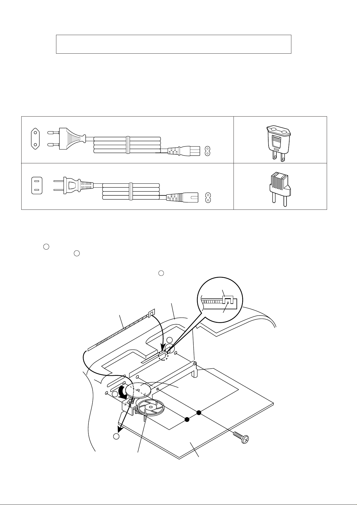
AC POWER SUPPLY CORD AND PLUG
9FF24801830210
9FF24801600292 9FF26802125210
9FF26802125120
FITTING OF DIAL POINTER
1. Remove the main PWB. Attach the dial pointer as shown
A
arrow on the front cabinet, putting it into the section
indicated by arrow .
2. Install the main PWB in the front cabinet and secure it with
the four screws.
3. Turn the tuning control knob in the direction indicated by .
Set the dial pointer to point "0", and then make the rest of
the adjustments.
B
C
Front Cabinet
Dial Pointer (234)
C
Dial Pointer
(234)
"0" Point
A
Tuning Control
Knod (233)
B
Dial Drum (231)
Screw (608)
ø3x10mm
Main PWB
Figure 2
– 2 –
Page 3
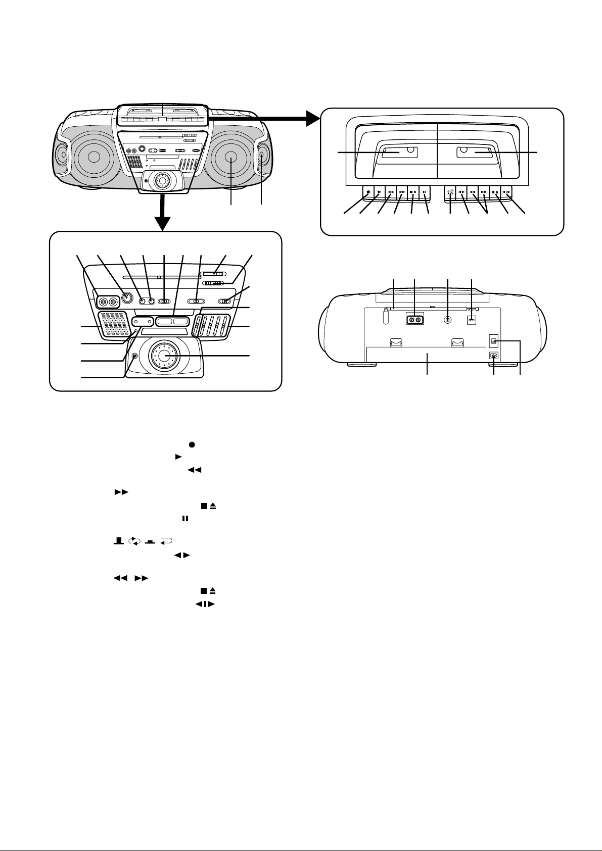
NAMES OF PARTS
WQ-790W
16
17 18 19 20 2122 23 24
25
26
27
28
11.
(TAPE 1) Cassette Compartment
12.
(TAPE 1) Record Button:
13.
(TAPE 1) Play Button:
14.
(TAPE 1) Rewind Button:
15.
(TAPE 1) Fast Forward Button:
16.
(TAPE 1) Stop/Eject Button:
17.
(TAPE 1) Pause Button:
18.
(TAPE 2) Reverse Mode Switch:
19.
(TAPE 2) Play Button:
10.
(TAPE 2) Fast Wind Buttons:
/
11.
(TAPE 2) Stop/Eject Button:
12.
(TAPE 2) Direction Switch:
1
14 15
29
30
31
32
13.
(TAPE 2) Cassette Compartment
14.
Full-Range Speaker
15.
Surround Speaker
16.
Mixing Microphone Sockets
17.
Mixing Microphone Volume
Control
18.
Surround On/Off Switch
19.
Surround Mode Select Switch
20.
Function Selector Switch
21.
Surround Mode Indicators
22.
Band Selector Switch
23.
Tuning Control
24.
Fine Tuning Control
25.
Spectrum Analyzer
26.
FM Stereo Indicator
789101112
65432
33
34 35 36
37 38 39
27.
Power/(TAPE 2) Play Direction
Indicators
28.
Built-in Microphone
29.
Dubbing Speed/Built-in
Microphone/FM Mode Switch
30.
Extra Bass Control: X-BASS
31.
Graphic Equalizer Controls
32.
Volume Control
33.
FM/SW Telescopic Rod Aerial
34.
CD/Line Input Sockets
35.
Headphone Socket
36.
Beat Cancel Switch
37.
Battery Compartment
38.
AC Power Input Socket
39.
AC Voltage Selector
13
– 3 –
Page 4
WQ-790W
Front Cabinet
(D1)x5
ø3x10mm
(E3)x1
ø2x6mm
(E2)x2
ø3x10mm
Graphic
Equalizer PWB
Volume PWB
Lug Wire
(E1)x1
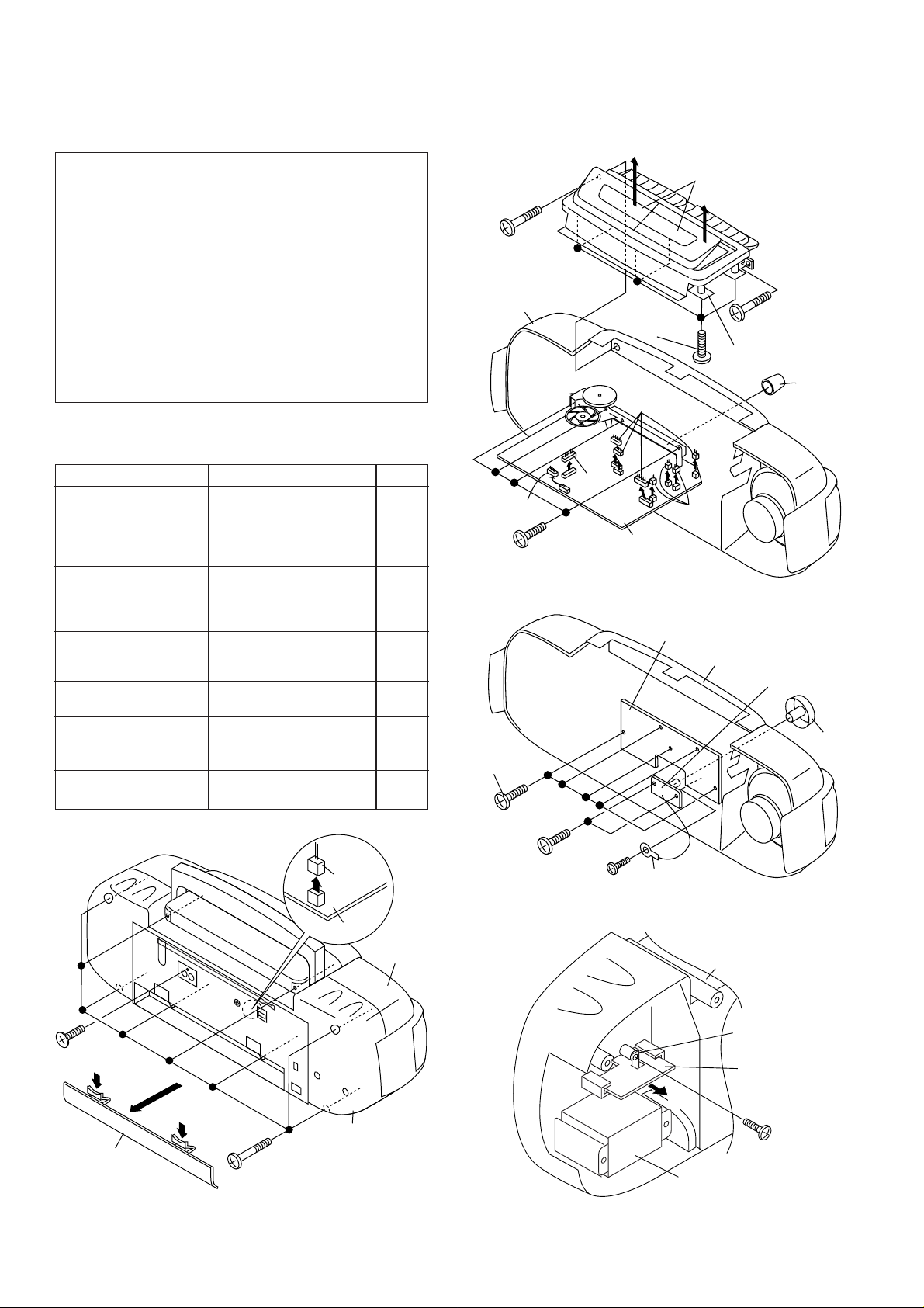
DISASSEMBLY
Caution on Disassembly
Follow the below-mentioned notes when disassembling
the unit and reassembling it, to keep it safe and ensure
excellent performance:
1. Take cassette tape out of the unit.
2. Be sure to remove the power supply plug from the wall
outlet before starting to disassemble the unit and remove
the batteries from the unit.
3. Take off nylon bands or wire holders where they need
to be removed when disassembling the unit. After
servicing the unit, be sure to rearrange the leads where
they were before disassembling.
4. Take sufficient care on static electricity of integrated
circuits and other circuits when servicing.
STEP REMOVAL PROCEDURE FIGURE
1 Front Cabinet/ 1. Battery Compartment Lid. 4-1
Rear Cabinet ................................. (A1)x1
2. Screw ................... (A2)x1
3. Screw ................... (A3)x8
4. Socket .................. (A4)x1
2 Tape mechanism 1. Screw ................... (B1)x2 4-2
2. Socket .................. (B2)x4
3. Open the cassette holder.
4. Screw ................... (B3)x6
3 Main PWB 1. Knob..................... (C1)x1 4-2
2. Screw ................... (C2)x4
3. Socket .................. (C3)x5
4 Graphic Equalizer 1. Screw ................... (D1)x5 4-3
PWB
5 Volume PWB 1. Knob..................... (E1)x1 4-3
2. Screw ................... (E2)x2
3. Screw ................... (E3)x1
6 Power PWB 1. Screw ................... (F1)x1 4-4
2. Bracket................. (F2)x1
(B1)x1
ø3x20mm
Front Cabinet
(C3)x1
(C2)x4
ø3x10mm
(B2)x1
Open
(B3)x6
ø3x10mm
(C3)x4
Main PWB
Figure 4-2
Casette Holder
(Left/Right)
Open
(B1)x1
ø3x20mm
Tape Mechanism
(C1)x1
(B2)x3
(A2)x1
ø2.6x10mm
(A1)x1
(A3)x8
ø3x20mm
Figure 4-1
(A4)x1
Main PWB
Rear
Cabinet
Front
Cabinet
Figure 4-3
Rear Cabinet
(F2)x1
Power
PWB
Pull
(F1)x1
ø3x10mm
Power
Transformer
Figure 4-4
– 4 –
Page 5
ADJUSTMENT
WQ-790W
MECHANISM SECTION
• Driving Force Check
Torque Meter
Play: TW-2412 Tape 1: Over 60 g
Specified Value
Tape 2: Over 50 g
• Torque Check
Torque Meter
Play: TW-2111 30 to 60 g.cm 30 to 60 g.cm
Fast forward: TW-2231 80 to 135 g.cm 55 to 120 g.cm
Rewind: TW-2231 80 to 135 g.cm 55 to 120 g.cm
Specified Value
Tape 1 Tape 2
• Head Azimuth
Test Tape
MTT-114 Headphones Socket
Instrument Connection
(Load resistance: 32 ohms)
* Open the cassette holder, and load the test tape directly into
the mechanism. (Do not load the tape into the cassette
holder.)
• Tape Speed (Normal only)
Test Tape
MTT-111 Tape 1,2:VR501 3,000 ± 60 Hz Headphones
Adjustment
Point
Specified
Value
Instrument
Connection
Socket
(Loadresistance:
32 ohms)
DECK SECTION
• Bias Oscillation
• Beat Cancel Switch: A
Adjustment Point Specified value Instrument
T301 100 kHz + 4 kHz Pin 1 of CNS108
Specified Value
Beat Cancel A: 100 ± 4 kHz
B: 94 ± 4 kHz
C: 104 ± 4 kHz
Connection
TUNER SECTION
fL: Low-range frequency
fH: High-renge frequency
• FM IF/RF
Test Stage
IF T201 Input: FM Antenna
Detection T202 Output:Pin 9 of IC202
Band fL: L202 Input: Antenna
Coverage fH: TC202 Output: Headphone Socket
Tracking fL(88.0 MHz): L201 (Load resistance:
Specified Value/
Adjusting
Point
fH(108 MHz): TC201 32 ohms)
• AM IF/RF
Test Stage
IF T203
MW Band fL: L203
Coverage fH: TC203
MW Tracking fL(600 kHz): L206
SW1 Band fL(2.3 MHz): L204
Coverage fH(7.3 MHz): TC204
SW1 fL(2.6 MHz): L207
Tracking fH(6 MHz): TC209
SW2 Band fL(7.3 MHz): L205
Coverage fH(22 MHz): TC205
SW2 fL(8.5 MHz): L208
Tracking fH(19 MHz): TC210
Specified Value/
Adjusting
Point
fH(1,400 kHz):TC207
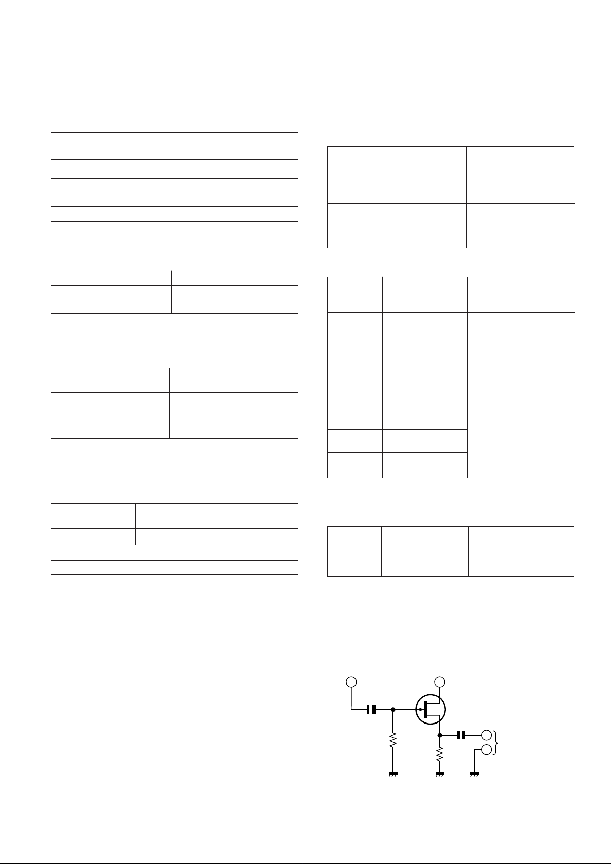
• VCO Frequency
Adjustment
Point
VR201 76 kHz ± 200 Hz Pin 13, Pin 21 and ground
Specified value Instrument Connection
Note:
After preparing the test circuit shown in Fig. 5, connect the Pin
13, Pin 21 and ground of the IC202 with the test circuit, and
measure the value.
Instrument
Connection
Instrument
Connection
Input: Antenna
Output: Pin 9 of IC202
Input: Antenna
Output: Headphone Socket
(Load resistance
32 ohms)
of IC202
Pin 13 of IC202
– 5 –
Pin 21 of IC202
D
G
10 pF
1M ohm
10K ohm
FET: 2SK212
(or Other 2SK Type FET.)
S
0.1 µF
TO FREQUENCY
COUNTER
Figure 5 VCO FREQUENCY TEST CIRCUIT
Page 6
WQ-790W
CNS110
T301
BIAS
OSCILLATION
CNS108
1
2
3
4
SW2
TRACKING
FM
TRACKING
FM
DETECTION
fH
fL
VCO
AM IF
VR201
TC210
L208
fH
T203
IC202
2113
fL
19
T202
TC209
FM IF
T201
IC201
L201
TC
201
TC
207
1
L202
TC
202
TC
203
L203
TC204
TC205
L205
L204
fH
FM BAND
COVERAGE
fL
fH
SW1 BAND
COVERAGE
fL
MW BAND
fL
COVERAGE
fL
SW2 BAND
COVERAGE
fH
MW BAND
fH
COVERAGE
MW
TRACKING
SW1
TRACKING
fH
fL
MW
L206
Figure 6 ADJUSTMENT POINTS
NOTES ON SCHEMATIC DIAGRAM
• Resistor:
To differentiate the units of resistors, The symbol as K and
M are used: the symbol K means 1000 ohm and the symbol
M means 1000 kohm and the resistor without any symbol
is an ohm resistor. The resistor designated “Fusible” is a
fuse type resistor.
• Capacitor:
To indicate the unit of capacitor, a symbol P is used: this
symbol P means pico-farad and the unit of the capacitor
without such a symbol is microfarad. As to electrolytic
capacitor, the expression “capacitance/withstand voltage”
is used.
(CH),(RH),(UJ): Temperature compensation
(ML): Mylar type
(S): Styrol type
• The indicated voltage in each section is the one measured
by Digital Multimeter between such a section and the
chassis with no signal given.
• Schematic diagram and Wiring Side of P.W. Board for this
model are subject to change for improvement without prior
notice.
• Parts marked with “ ” ( ) are important for
maintaining the safety of the set. Be sure to replace these
parts with specified ones for maintaining the safety and
performance of the set.
fH
fL
MAIN PWB
SW1
L207
REF. NO. DESCRIPTION
SW201 BAND SELECTOR FM
SW301 BEAT CANCEL C
SW302 RECORD/PLAYBACK PLAYBACK
SW401 SURROUND MODE LIVE
SELECT
SW402 SURROUND ON/OFF OFF
SW403 DUBBING SPEED/ HIGH/FM STEREO
BUILT-IN MICROPHONE/
FM MODE
SW404 FUNCTION SELECTOR TAPE
SW501 TAPE 2 MAIN OFF
SW502 TAPE 1 MAIN OFF
SW503 TAPE 2 PLAY OFF
SW504 TAPE 2 DIRECTION A
SW505 VOLTAGE SELECTOR AC220-240V
POSITION
– 6 –
Page 7

WQ-790W
CNS110
T301
BIAS
OSCILLATION
CNS108
1
2
3
4
SW2
TRACKING
FM
TRACKING
FM
DETECTION
fH
fL
VCO
AM IF
VR201
TC210
L208
fH
T203
IC202
2113
fL
19
T202
TC209
FM IF
T201
IC201
L201
TC
201
TC
207
1
L202
TC
202
TC
203
L203
TC204
TC205
L205
L204
fH
FM BAND
COVERAGE
fL
fH
SW1 BAND
COVERAGE
fL
MW BAND
fL
COVERAGE
fL
SW2 BAND
COVERAGE
fH
MW BAND
fH
COVERAGE
MW
TRACKING
SW1
TRACKING
fH
fL
MW
L206
Figure 6 ADJUSTMENT POINTS
NOTES ON SCHEMATIC DIAGRAM
• Resistor:
To differentiate the units of resistors, The symbol as K and
M are used: the symbol K means 1000 ohm and the symbol
M means 1000 kohm and the resistor without any symbol
is an ohm resistor. The resistor designated “Fusible” is a
fuse type resistor.
• Capacitor:
To indicate the unit of capacitor, a symbol P is used: this
symbol P means pico-farad and the unit of the capacitor
without such a symbol is microfarad. As to electrolytic
capacitor, the expression “capacitance/withstand voltage”
is used.
(CH),(RH),(UJ): Temperature compensation
(ML): Mylar type
(S): Styrol type
• The indicated voltage in each section is the one measured
by Digital Multimeter between such a section and the
chassis with no signal given.
• Schematic diagram and Wiring Side of P.W. Board for this
model are subject to change for improvement without prior
notice.
• Parts marked with “ ” ( ) are important for
maintaining the safety of the set. Be sure to replace these
parts with specified ones for maintaining the safety and
performance of the set.
fH
fL
MAIN PWB
SW1
L207
REF. NO. DESCRIPTION
SW201 BAND SELECTOR FM
SW301 BEAT CANCEL C
SW302 RECORD/PLAYBACK PLAYBACK
SW401 SURROUND MODE LIVE
SELECT
SW402 SURROUND ON/OFF OFF
SW403 DUBBING SPEED/ HIGH/FM STEREO
BUILT-IN MICROPHONE/
FM MODE
SW404 FUNCTION SELECTOR TAPE
SW501 TAPE 2 MAIN OFF
SW502 TAPE 1 MAIN OFF
SW503 TAPE 2 PLAY OFF
SW504 TAPE 2 DIRECTION A
SW505 VOLTAGE SELECTOR AC220-240V
POSITION
– 6 –
Page 8

VOL T AGE
IC201 (LA1186N): FM Front End
PIN
FM
AM
TAPE
1V
0V
0V
1.8V
0V
0V
0V
0V
0V
0V
0V
0V
0V
0V
0V
5V
0V
0V
1.4V
0V
0V
4V
0V
0V
5V
0V
0V
123456789
IC101-105 (AN6884): Spectrum Analyzer
6.13V
6V
6V
6.16V
6V
6V
6V
6V
6V
6V
6V
6V
0V
0V
0V
6V
6V
6V
0V
0V
0V
0V
0V
0V
6.5V
6.5V
6.5V
123456789
IC202 (LA1805): IF Amp, & FM MPX.
PIN
FM
AM
TAPE
1.4V
1.6V
0V
1.4V
1.6V
0V
5.6V
6V
0V
0.6V
0.6V
0V
1.5V
0V
0V
0V
0V
0V
0V
0V
0V
0V
0V
0V
2.3V
2.4V
0V
2.3V
2.4V
0V
5V
0.5V
0V
1V
1V
0V
123456789101112
PIN
FM
AM
TAPE
1V
1.8V
0V
1V
1.8V
0V
2V
1.8V
0V
1V
1.8V
0V
1.8V
1.8V
0V
1.5V
1.6V
0V
1.6V
0.6V
0V
0.4V
6.6V
0V
5.7V
6.6V
0V
5.7V
1.67V
0V
1.62V
1.67V
0V
1.62V
1.4V
0V
13 14 15 16 17 18 19 20 21 22 23 24
IC301 (TA8189N): Record/Playback Amp.
PIN
RADIO
TAPE PLAY
TAPE REC
0.98V
0.98V
0.98V
0.98V
0.98V
0.98V
2.11V
2.11V
2.11V
1.57V
1.6V
1.6V
5.7V
5.7V
5.7V
4.8V
4.8V
4.8V
0V
0V
0V
0V
0V
0V
2V
2V
2V
1.2V
1.2V
1.2V
0V
0V
0V
0V
0V
0V
123456789101112
PIN
RADIO
TAPE PLAY
TAPE REC
1.4V
1.4V
1.4V
0V
0V
0V
1.29V
1.29V
1.29V
2V
2V
2V
1.4V
1.4V
1.4V
5.8V
5.8V
5.8V
0V
0V
0V
5.7V
5.7V
5.7V
5.3V
5.3V
5.3V
2V
2V
2V
1V
1V
1V
1V
1V
1V
13 14 15 16 17 18 19 20 21 22 23 24
IC402 (LA4558): Power Amp.
14.5V
14.5V
14.5V
0.01V
0.01V
0.01V
1.1V
1.1V
1.1V
7.6V
7.6V
7.6V
0.6V
0.6V
0.6V
13.6V
13.6V
13.6V
0V
0V
0V
15V
15V
15V
13.7V
13.7V
13.7V
0.6V
0.6V
0.6V
12345678910
7.6V
7.6V
7.6V
1.1V
1.1V
1.1V
0.01V
0.01V
0.01V
0V
0V
0V
11 12 13 14
IC401 (BA4558): Ope Amp.
PIN
RADIO
TAPE PLAY
TAPE REC
PIN
RADIO
TAPE PLAY
TAPE REC
PIN
RADIO
TAPE PLAY
TAPE REC
PIN
RADIO
TAPE PLAY
TAPE REC
3.3V
3.3V
3.3V
3.3V
3.3V
3.3V
3.3V
3.3V
3.3V
0V
0V
0V
3.3V
3.3V
3.3V
3.3V
3.3V
3.3V
3.3V
3.3V
3.3V
6.7V
6.7V
6.7V
12345678
IC106-108 (BA4558): Ope Amp.
PIN
RADIO
TAPE PLAY
TAPE REC
6V
6V
6V
6V
6V
6V
6V
6V
6V
0V
0V
0V
6V
6V
6V
0V
0V
0V
6V
6V
6V
7V
7V
7V
12345678
Q101
Q102
Q103
Q106
Q107
Q108
Q202
Q203
Q301
Q302
Q303
Q401
Q402
Q501
Q502
Q503
Q504
Q505
Q506
Q507
Q508
Q509
e
0V
0V
7.36V
0V
7.38V
7.98V
0.32V
0.32V
0V
0V
0.5V
0V
0V
7.43V
0V
–1.74V
0V
0V
15.01V
0V
1.93V
0V
b
0.63V
0.63V
6.52V
0.69V
6.54V
7.37V
0.98V
0.98V
0.27V
0V
1.18V
0V
0V
8.06V
0V
0V
0.7V
0V
14.23V
0.74V
2.57V
0V
c
3.27V
3.35V
7.28V
0.1V
7.3V
13.67V
2.88V
2.85V
0.27V
0.4V
5.53V
0V
0V
13.14V
0V
–
0V
0.7V
14.98V
0.12V
3.82V
0V
e
0V
0V
7.36V
0V
7.38V
7.98V
0.32V
0.32V
0V
0V
0.5V
0V
0V
7.43V
15V
0V
0V
15.01V
0V
1.93V
0V
b
0.63V
0.63V
6.52V
0.69V
6.54V
7.37V
0.98V
0.98V
0.27V
0V
1.18V
0V
0V
8.06V
0V
0.70V
0V
14.23V
0.74V
2.57V
0V
c
3.27V
3.35V
7.28V
0V
7.3V
13.67V
2.88V
2.85V
0.27V
0.4V
5.53V
0V
0V
13.14V
8.8V
0V
0.7V
14.98V
0.12V
3.82V
0V
e
0.05V
0.5V
15V
–
0V
0V
1.93V
b
–0.18V
1.18V
0V
0.7V
0.74V
2.57V
c
6.2V
5.53V
8.8V
0.12V
3.82V
RADIO TAPE RECTAPE PLAY
TRANSISTOR
WQ-790W
FRONT
VIEW
2SB1370
2SD2061
8050 C
E B C
Figure 7 TYPE OF TRANSISTOR AND LED
9014 C
9015 C
9012 G
IFR-523 HD
IFR-553 PD
FRONT
VIEW
– 7 –
Page 9

WQ-790W
I
D
A
C
0
M
E
E
FM/SW
ROD ANTENNA
A
B
C
TAPE1
RECORD/PLAYBACK
HEAD
L-CH
D
R-CH
+
ERASE
HEAD
E
TAPE2
PLAYBACK HEAD
SW504-A
SIDE-A
L-CH
R-CH
SIDE-B
CD/LINE
J2
B
B
A
SW504-B
SW504
TAPE2
DIRECTION
SIDE-B
SIDE-A
F
G
H
A
L-CH
GND
R-CH
CNH108
4 4
CNH107
1 1
2 2
3 3
CNS108
1 1
2 2
3 3
CNS107
R452
47K
R451
47K
LA
GA
BA
RA
LB
GB
RB
R454
2.2K
R453
2.2K
D202
1N4148
VC203
SW201-C
TRACKING
SW201
BAND SELECTOR
SW201-B
SW201
BAND SELECTOR
MW
TRACKING
SW201-F
FM
MW
SW1
SW2
FM
MW
SW1
SW2
TC210
fH
SW2
fL
SW302
RECORD/PLAYBACK
SW302-B
PR PR
SW302-E
P R
C515
130P
L303
C517
22mH
150P
SW301
BEAT CANCEL
ABC
C357
120P
C201
0.001
FM
MW
1 2 3
SW1
SW2
fL
fH
C516
150P
SW302-C
P R
FM RF
L201
fL
FM
TRACKING
TC209
L206,L207
MW/SW1 BAR
ANTENNA
C245
12P(CH)
SW302-D
C356
430P
CF201
BAND PASS
FILTER
108MHz
C203
22P(CH)
C204
fH
0.001
TC207
7P(CH)
C244
5P(CH)
C321
130P
L304
22mH
C301
0.001(ML)
C303
470P
C302
0.001(ML)
C527
470P
R321
12K
AC BIAS CIRCUIT
C355
0.0015(ML)
T301
BIAS
OSCILLATION
C243
C304
470P
FM SIGNAL
MW/SW1/SW2 SIGNAL
PLAYBACK SIGNAL
RECORD SIGNAL
IC201
LA1186N
FM FRONT END
1
2 3 4
5
C202
0.001
TC201
VC201
R201
C211
10
0.022
L206
FM
MW
SW1
SW2
MW
ANTENNA
L207
SW1 ANTENNA
L208
SW2 ANTENNA
C307
0.033(ML)
C365
330P
24
1 2 3 4
C366
330P
FINE TUNING
R322
12K
C528
470P
R326
R305
33K
56
R311
150K
3.9K
R307
C305
33/16
R303
180K
C363
330P
20
23
22
21
RECORD/PLAYBACK AMP.
5
3.9K
R310
C364
330P
R304
180K
C306
C308
33/16
0.033(ML)
R306
56
R333
27K
C353
0.0056(ML)
C354
0.01(ML)
R308
R332
150K
10
6
8
7
C207
3P
C206
20P(CH)
FM
OSCILLATION
L202
TC202
R203
22K
C210
10/16
SW201-E
R219
100
SW201
BAND SELECTOR
fL
SW1
TRACKING
fH
SW201-G
C241
3P(CH)
R220
220
VC204
VR202
5K(B)
Q509 9014 C
DUBBING CONTROL
R559
100K
C325
47/16
C327
1000/10
4.7K
R309
C309
4.7/50
C326
2.2/50
17
19
18
IC301
TA8189N
8
6
7
C310
4.7/50
4.7K
R312
R324
10K
R325
C323
22/16
Q301
8050 C
BIAS OSC.
C352
100/16
C320
10K
FM
MW
SW1
SW2
C351
9
R202
33
16
9
4.7/50
0.022
C208
VC202
R205
220K
33P(CH)
D203
1N4148
R204
100
C238
360P
TC203
C239
0.0022
TC204
C240
0.0047
TC205
fH
SW2 BAND
COVERAGE
100
R328
C319
4.7/50
R317
180K
15
10
R320
180K
C318
10/16
R368
18K
SW302-A
R330
fL
fH
fL
L361
2.7mH
R319
2.2K
C317
10/16
14
11
R318
2.2K
R323
10K
100
P
R
R362
L302
2.7mH
SW302-F
FM BAND
COVERAGE
T201
FM IF
MW BAND
COVERAGE
fH
10P(CH)
C236
5P(CH)
C237
5P(CH)
C361
0.015(ML)
R361
270
13
12
C316
330P
270
C362
0.015(ML)
PR
SW403-B
R207
820K
C212
0.022
FM DETECTION
C214
0.022
R206
47
fL
C235
L203
MW OSC.
L204
SW1 OSC.
L205
SW2 OSC.
R327
100K
C311
0.0082(ML)
R367
18K
R315
330K
C313
4.7/50
C315
330P
C338
47/16
R364
1M
C314
4.7/50
R314
22K
330K
R316
C312
0.0033(ML)
SW403
DUBBING SPEED/
BUILT-IN MICROPHONE/
FM MODE
HIGH/
FM STEREO
NORMAL/FM STEREO
MIC/
FM
MONO
SW302
RECORD/
PLAYBACK
R336
100
FM IF
CF202
10.7MHz
1 2 3
SW201-H
fL
fH
C242
0.022
0.0033(ML)
R313
22K
18K
R250
TAPE
RADIO
0.0082(ML)
C521
R512
10K
10K
R513
9014 C
SPEED
CONTROL
T202
R222
47
SW1 BAND
COVERAGE
C520
C261
CD/LINE
Q505
TAPE
R208
3.9K
24
C213
10/16
2
1
C231
0.022
C229
0.022
R221
47
FM
MW
SW1
SW2
R223
47
R532
47K
RADIO
CD/LINE
TAPE
SW404-C
C260
1/50
R240
150K
R249
18K
Q202
9014 C
LINE AMP
C258
R245
1/50
100
C259
1/50
R241
150K
R247
1/50
SW404-D
SW404
FUNCTION SELECTOR
R355
18K
TAPE SPEED
R533
VR501
47K
470(B)
Q503
9015 C
TAPE
SPEED
CONTROL
R510
10K
R508
10K
Q504
9014 C
TAPE
SPEED
CONTROL
C218
0.0047(ML)
22
21
23
20
IF AMP.& FM MPX.
4
3
5
C230
22/16
T203
AM IF
CF203
460kHz
AM IF
FM
SW201-A
MW
SW1
SW2
C233
0.022
SW201
BAND SELECTOR
D521
1N4148
SW404
FUNCTION
SELECTOR
R354
18K
R246
1K
C262
1/50
C401
470/16
R243
100
Q203
9014 C
LINE AMP
C263
1/50
1K
R561
47
R506
3.9K
R560
56K
R209
12K
19
IC202
LA1805
6
1
2
C228
1/50
R214
R401
100
3
12K
1N4148
R562
2.7K
R216
18
7
2.2K
D201
R563
R404
C219
2.7K
10K
R403
10K
C220
470P
0.0082(ML)
C221
3.3/50
16
17
8
9
C226
0.012(ML)
C227
1/50
OPE AMP.
R407
2.7K
OPE AMP.
C512
0.1
C222
3.3/50
14
15
11
10
C225
0.012(ML)
SW1
SW2
R213
12K
R215
2.2K
IC401
BA4558
3
2
R410
2.7K
12K
R408
C408
C410
0.0033(ML)
4.7/50
C411
4.7/50
C409
R409
0.0033(ML)
12K
IC401
BA4558
C404
10/16
KA7809
VOLTAGE
REGULATOR
1
C511
220/16
13
12
R212
10
SW201-D
FM
MW
8
+
(1/2)
–
R412
12K
R411
12K
6
–
+
5
IC502
C224
1/50
D516
1N4148
R406
330
R405
10K
R413
10K
(2/2)
4
2
R218
R210
150K
100
1
7
3
NORMAL/FM ST
HIGH/FM ST
VR201
10K(B)
VCO
C256
0.022
D527
1N4148
C534
4.7/50
C412
1/50
C416
220/16
C415
100/16
C413
1/50
L501
47µH
MIC/FM
R211
15K
C529
0.022
C232
220/16
CD/L
RA
R416
R415
T
10K
10K
• NOTES ON SCHEMATIC DIAGRAM can be found on page 6.
1
2
34 5
Figure 8 SCHEMATIC DIAGRAM (1/4)
– 8 –
6
Page 10

WQ-790W
78 9101112
6
SW403
DUBBING SPEED/
BUILT-IN MICROPHONE/
FM MODE
MIC/FM MONO
AL/FM STEREO
GH/FM STEREO
R211
15K
O
C529
0.022
C232
220/16
6
2
27
148
12
0
6
0.0015
CD/LINE
RADIO
TAPE
10K
R416
10K
R415
C223
C407
10/16
R217
330
D526
1N4148
SW404-A
SW404
FUNCTION
SELECTOR
C530
4.7/50
SW403-A
C414
0.0033(ML)
C417
0.0033(ML)
D515
1N4148
D520
1N4148
R345
1K
R341
10K
Q302
9014 C
MUTE
R531
1K
R566
100K
D305
470/16
27K
R440
1N4148
R564
C342
22K
C440
R567
22K
10/16
D525
D524
C535
4.7/50
VR301
50K(B)
1N4148
1N4148
1N4148
C533
4.7/50
Q508
9014 C
MIC AMP.
MIC
VOLUME
1N4148
D523
R557
1K
R558
SW402
SURROUND
ON/OFF
D402
Q510
9014 C
MUTE
0.1
C508
C507
100/16
C537
10/16
R568
1K
R565
5.6K
R556
150K
C532
500P
33
R351
1K
SW401
SURROUND
MODE SELECT
SW402-B
ON
D517
1N4148
FUSE
RESISTOR
C505
10/16
C341
4.7/50
C536
47/16
LIVE
SW401-C
OFF
R421
10K
R442
10K
R441
10K
R420
10K
R501
Q501
8050 C
VOLTAGE
REGULATOR
R548
100
D522
1N4148
R502
680
D505
CD/LINE
FUNCTION
SELECTOR
R344
4.7K
R343
330
R350
3.9K
HALL
4.7
FUSIBLE
RADIO
SW404
R450
4.7K
POWER MUTE
POWER MUTE
D518
1N4148
SWITCHING
D509
1N4001
SW404-B
TAPE
Q303
9014 C
MIC AMP.
C343
500P
D519
1N4001
Q402
9014 C
Q401
9014 C
Q506
2SB1370
R545
22K
C522
3300/25
D507
1N4001
C422
C421
1/50
R346
470K
0.0047(ML)
SW402
SURROUND ON/OFF
SW402-A
ON OFF
MODE SELECT
SW401-D
LIVE
HALL
C424
0.0015(ML)
1/50
C426
100/16
C425
100/16
C423
0.0015(ML)
F1
T1.25A
L250V
R535
330/1W
R537
10K
R419
3.3K
R418
3.3K
CNS101
CNS105
C344
4.7/50
C345
HALL
SW401-B
SURROUND
VCC
GND
LO0
RO0
RI0
LI0
R552
4.7K
R555
4.7K
C347
10/16
LIVE
SW401
5
2
3
14
IC402
LA4508
12
13 11
1
D401
1N4001
C469
220/16
SWITCHING
Q507 9014 C
CNH110
CNS110
1
1
2
2
CNS102
5
5
4
4
3
3
2
2
1
1
CNH102
1
2
3
4
5
6
FROM GRAPHIC EQUALIZER PWB
1 1
2 2
3 3
4 4
5 5
6 6
+
7 7
–
8 8
B
9 9
A
10 10
CNS1
R554
R553
680
680
R349
2.2K
SW401
SURROUND
MODE SELECT
SW401-A
LIVE
HALL
C459
2.2/50(N.P)
C427
0.01(ML)
C428
0.01(ML)
10
4
6
C430
100/16
7
C429
100/16
9
POWER AMP.
8
C437
470/25
POWER PWB-C
C502
0.1
D504D503
C504
0.1
C503
D501~D504'RL202DC
5
C471
820P
1
CN205
P12 1-C
SW502
TAPE1 MAIN
SW501
TAPE2 MAIN
SW503
TAPE2 PLAY
M501
M
TAPE MOTOR
1000/10
0.18(ML)
0.18(ML)
1000/10
0.1
0.1
C501
VR401-B
C346
4.7/50
C434
C432
C431
C433
T2A L250V
D501
D502
R471
8.2K
50K(B)
VOLUME
C450
2.2/50(N.P)
F501
C473
0.068
R534
4.7K
R422
120
R423
120
T501
POWER
TRANSFORMER
BATTERYS
DC15V[" D " ISIZE(UM/SUM-1,
R20 OR HP-2)BATTERYx10]
R472
8.2K
C472
0.068
VR401-A
VOLUME
MIC2
MIC1
1 1
2 2
CNS109 CNH109
CN2 CNS2
1 2 1
2
1
2
FROM GRAPHIC
EQUALIZER PWB
3
4
5
6
7
CN4
CNS106
CNH106
TWL
1
1
L-CH
2
2
GND
3
3
GND
4
4
R-CH
5
5
TWR
6
6
J1
HEADPHONES
SW505
VOLTAGE
SELECTOR
AC220-240V
50/60Hz
AC110-127V
50/60Hz
C474
820P
50K(B)
VOLUME PWB-B1
MICROPHONES
BUILT-IN
MICROPHONE
MIC101
SW504-C
B
A
SW504
TAPE2 DIRECTION
CN207
P12 1-F
SP4
SURROUND
L-CH SPEAKERS
SP2
FULL-RANGE
SP1
FULL-RANGE
R-CH SPEAKERS
SP3
SURROUND
SO501
AC POWER
INLET SOCKET
AC110-127V/
220-240V
50/60Hz
MAIN PWB-A
Figure 9 SCHEMATIC DIAGRAM (2/4)
– 9 –
Page 11

WQ-790W
D125
D120
D115
D110D105
D104
D108
D103
D102
D101
R603
R602
R601
R610
R611
C145
C144
D113
R615
D114
D109
D119
R619
R614
R613
R607
R606
D107
D106
R618
R617
R622
R621
C153
R616
R612
C147
C148
C151
C142
C141
C140
C143
IC108
R167
R169
R164
R163
R156
R159
R160
R158
R173
R171
R175
R177
C154
IC101
IC102
IC103
IC104
IC105
C150
R636
R638
D134
1
1234567
7
R152
R137
R112
R111
R116
R118
R122
R117
R123
D131
R155
Q107
Q106
C191
CN207
SPECTRUM
ANALYZER
R627
D127
R180
Q103
C180
R628
D132 D128
D135
C134
C133
R150
R650
R642
C181
C182
C183
C184
R184
C185
R643
R629
R651
D129
D133
IC106
R144
R142
R644
R106
R110
R141
R641
C127
R632
R631
C177
C125
C116
C118
Q101
Q102
C176
R135
C124
C105
VR102
VR101
R645
C105
C108
C110
C107
C111 C114
C109
C112
VR103
VR104
R124
C120
R136
R138
C102
C103
C126
C122
R130
R103
CN205
R101
R102
R104
R191
VR105
R134
R129
C113
R132
R131
R133
R127
C119
C121
R128
R107
R115
R114
R120
R121
R126
R125
R119
R113
R108
R109
C115
C117
R176
C128
C123
R148
C129
R145
C106
8
1
2
3
1
2
3
7
6
8
7
6
5
5
4
4
81
2
3
7
6
5
4
R143
C130
R183
D136
R182
R181
C135
R154
C138
R153
R165
R168
C152
R172
R147
IC107
C132
R149
R146
C131
C155
C149
C146
R151
R640
D126
D130
C139
R157
R637
R626
R623
D121
D122
D116
D111
D117
D112
D118
D124
R625
R620
R624
R609
R605
R608
R604
D123
CNH102
R472
C472
C474
VR401
C471
C473
E B C
C
B
E
C
B
E
E
B
C
1
2
3
4
5
6
7
8
9
1
2
3
4
5
6
7
8
9
1
2
3
4
5
6
7
8
9
1
2
3
4
5
6
7
8
9
1
2
3
4
5
6
7
8
9
VOLUME PWB-B1
1
6
ABABABABA
B
E C B
1
2
3
4
5
6
7
8
9
10
1
2
3
4
5
GRAPHIC EQUALIZER PWB-B2
TAPE 1
TAPE 2
M501
TAPE MOTOR
A B + -
SP2
FULL-RANGE
SP4
SURROUND
L-CH
SP1
FULL-RANGE
SP3
SURROUND
R-CH
CNH106
WH
RD
BK
BK
RD
WH
TAPE MECHANISM
GND
RECORD/PLAYBACK
HEAD(300-4)
ERASE HEAD(300-5)
WH
WH
WH
BK
BK
BK
BK
BK
RD
RD
RD
CNS1
WH
WH
GR
GR
BL
BL
RD
BK
YL
PK
SW502
TAPE1 MAIN
SW503
TAPE2 PLAY
SW501
TAPE2 MAIN
PLAYBACK
HEAD (300-6)
CNS2
GY
CNH107
RD
BK
RD
BK
RD
RD
AB
SW504
TAPE2
DIRECTION
BR
COLOR
TABLE
RD(R)
OR
YL
GR
BL
VL
GY
WH(W) BK
PK
BROWN
RED
ORANGE
YELLOW
GREEN
BLUE
VIOLET
GRAY
WHITE
BLACK
PINK
VOLUME
1
5
R471
1 2 3 4 5 6
2
1
HEAD
FLEXIBLE PWB
3
2
1
6
5
4
3
2
1
VR102~VR105
GRAPHIC EQUALIZER
10KHz 3.3KHz 1KHz 330Hz
VR101
X-BASS
A
B
C
D
E
F
G
H
1
2
34 5
Figure 10 WIRING SIDE OF P.W.BOARD (1/3)
6
– 10 –
Page 12

C
SW301
BEAT CANCEL
FROM
POWER PWB
CNH110
P14 5-C
L-CH
J2
CD/LINE
R-CH
B
A
J1
HEADPHONE
SW301
2 1
CNS110
J2
C522
6
5
4
3
2
1
R422
R423
C
B
A
Q507
CNS106
C459
C450
C353
C357
R333
R452
R454
R453
R451
C356
E
B
C
R535
E
Q301
B
C
C354
T301
F1
T1.25A L 250V
C355
R537
B C E
Q506
C437
C433
C429
C431
C430
C432
C434
IC502
321
R568
C537
D507
CNS105
1 2 3 4 5 6 7 8 9 10
TAPE SPEED
Q504
Q505
C511
E B C
E B C
R332
D401
R510
R513
L501
C351
14
13
12
11
10
9
8
7
6
5
4
3
2
1
C535
C352
R545
IC402
C512
D509
VR501
R560
R506
R561
E B C
R508
R512
R330
Q503
D518
R501
D523
C428
C427
C469
D524
Q203
R241
D522
Q501
R567
C263
C426
R247
C
B
E
C425
E B C
R564
R502
Q510
C262
C B E
C423
C424
C401
R548
C421
C
B
E
R563
D519
R243
E
B
C
C422
C261
C259
Q401
CN4
C507
R562
1
2
3
4
5
6
7
Q402
D525
R246
R401
D505
R421
R441
R442
R420
C B E
R245
C505
R240
C508
C260
1
2
D526
D515
Q202
D305
C258
WQ-790W
BK
RD
BK
R532
C409
R344
Q508
C527
R324
R450
C241
R350
R557
CNH109
R343
C536
E
B
Q303
C
R558
E
B
C
R368
R323
R341
E
B
C
Q302
R355
R354
C
D
R566
L208
C238
C242
C347
C343
R346
C532
C533
C323
R533
SW401
SW404
R220
C240
RD
C521
B
A
R556
R531
R349
1
2
R534
C344
C341
SW402
C
D
E
F
G
H
A
MIC101
BUILT-IN
MICROPHONE
CNS109
C345
C346
R553
R552
R555
VR301
B
A
B
A
D507
D
C
B
D202
A
C233
VR202
SW403
B
MIC1MIC2
MICROPHONES
R554
VR301
MIC VOLUME
MIN
MAX
SW402
SURROUND
ON/OFF
ON OFF
SW401
SURROUND
MODE SELECT
HALL
LIVE
SW404
FUNCTION
SELECTOR
CD/LINE RADIO TAPE
SW201
SW201
BAND SELECTOR
SW2 SW1 MW FM
FINE TUNING
MIC
NORMAL
SW403
DUBBING SPEED/
HIGH
BUILT-IN MICROPHONE/FM MODE
STAND-BY
ON
FM STEREO FM MONO
BK
BK
WH
RD
1 2 3 4 1 2
CNH108
R351
5
C413
13
24
R306
1
12
C412
R211
TC207
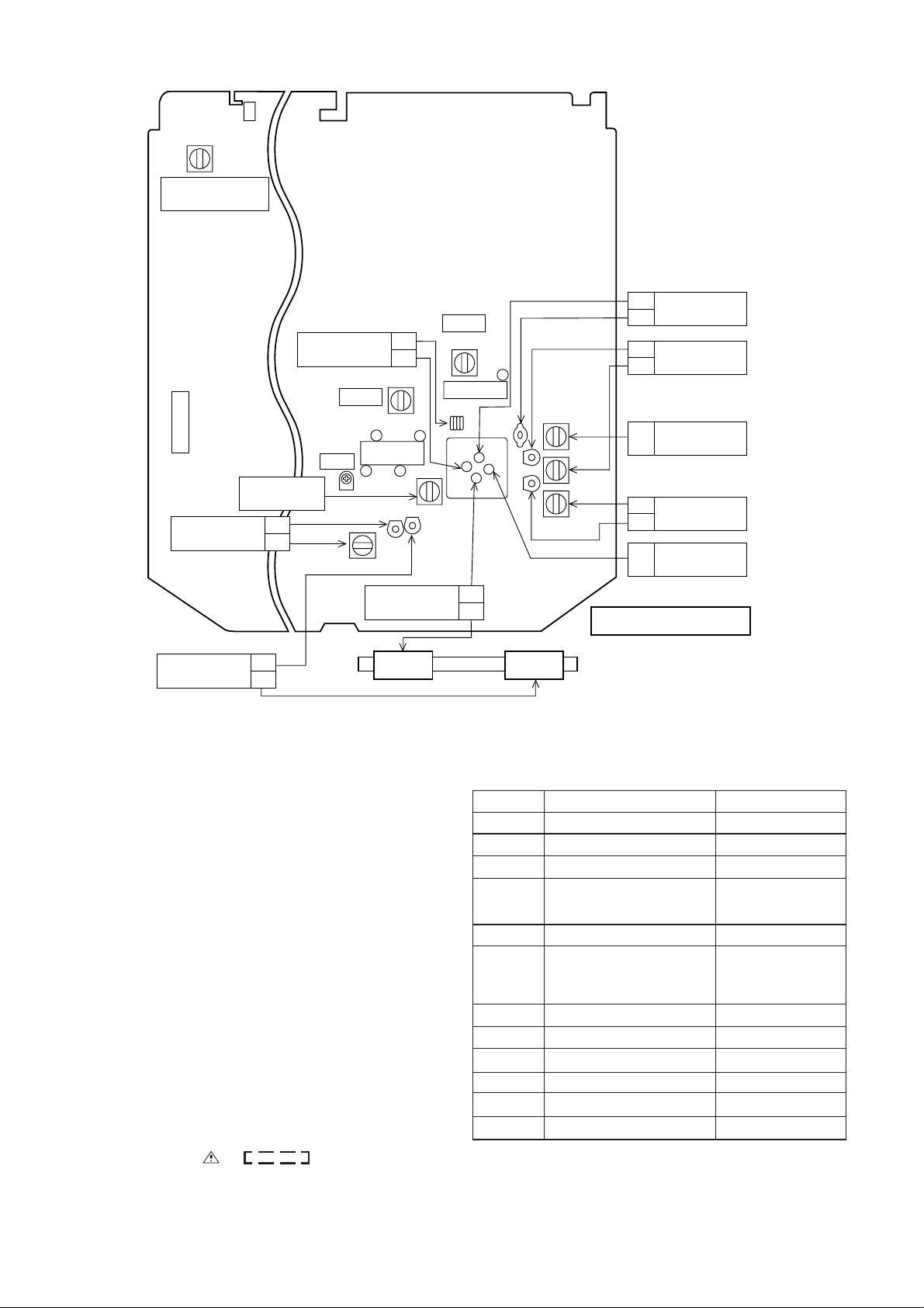
VC203
VC204
TC203
L204
1
8
R406
VCO
C221
C236
C308
C364
R325
C314
R412
R410
2
VR201
TC205
C366
C316
R409
R411
R219
T202
C312
R250
R408
3
657
R308
C318
R404
C517
4
C219
C218
C306
R304
R314
R403
R407
R210
R209
R208
L205
L303
C515
R310
R320
R316
R362
C362
D516
C222
C237
C310
C320
C410
IC401
C411
C220
R223
R312
C243
R318
R555
D517
R207
L302
C520
R405
R218
C534
TC209
C239
SW302
C342
R321
C408
C415
R413
C212
C245
TC210
C244
RECORD/
PLAYBACK
E B C
C440
D201
R559
Q509
D520
T201
PALY REC.
R322
C528
C319
L361
D521
R215
R217
C529
C229
C231
CF202
1 2 3
R206
R203
D203
C211
C210
R204
R205
R336
R309
R307
C305
C309
R303
R317
C317
R315
R319
R361
C361
C311
R249
R326
R367
R327
1
2
3
4
6
CNS102
5
5
4
3
CNS101
2
1
C227
R216
R214
R213
C228
T203
R201
C201
1
2
3
4
5
6
7
8
9
C208
IC201
CN2
R345
C530
D402
R440
C202
R202
C321
R311
C313
R328
C207
R419
C224
C204
C315
CF203
1
2
3
L201
L202
C307
R313
C226
C230
CF201
3 2 1
R221
C516
C325
R212
BCDEFA
R305
C363
C407
C326
R364
R418
C232
C225
C235
C338
12
10
L203
C303
C301
24
C365
13
5
1
C203
C206
1 2 3 4
CNS108
CNS107
1 2 3
20
15
C327
R416
C414
C416
C417
R415
TC201
VC201
VC202
TC202
TC204
C304
C302
IC301
10
C404
C223
C256
15
20
IC202
C214
C213
R222
L304
SW302
MAIN PWB -A
(281)
FM/SW ROD ANTENNA(277)
L206
MW
MW/SW1
BAR ANTENNA
L207
SW1
78 9101112
Figure 11 WIRING SIDE OF P.W.BOARD (2/3)
– 11 –
Page 13

WQ-790W
A
B
TO MAIN PWB
C
D
CNS101
P9 10-G
CN205
1
2
3
4
5
6
FM SIGNAL
R112
8.2K
(ML)
C108
0.01
R114
8.2K
R108
12K
0.022(ML)
0.01(ML)
C115
0.022(ML)
VR102-A
VR102-B
330Hz 1kHz 3.3kHz 10kHz
100K(B)
VR102-A
R116
5.6K
C116
100K(B)
VR102-B
R115
5.6K
X-BASS
VR101-A
VR101-B
R106
12K
0.1
C102
C103
470/16
R191
100
1
6
R101
1K
R102
1K
R103
560
C105
0.022
R105
12K
C106
R104
560
0.022
68K
R645
68K
R644
VR101-B
50K(B)
VR101-A
R110
R111
50K(B)
18K
R109
R107
18K
8.2K
C107
R113
8.2K
12K
R118
4.7K
C110
0.0068(ML)
R120
4.7K
0.022(ML)
R117
4.7K
C109
0.0068(ML)
R119
4.7K
C117
0.022(ML)
C118
R121
2.2K
GRAPHIC EQUALIZER
VR103-A
VR103-B
VR103-A
R122
2.2K
100K(B)
VR103-B
R124
3.3K
100K(B)
C112
0.0022(ML)
R126
3.3K
0.012(ML)
R123
3.3K
C111
0.0022(ML)
R125
3.3K
C119
0.012(ML)
VR104-A
VR104-B
C120
R127
1.5K
R128
1.5K
100K(B)
VR104-B
R130
820
100K(B)
VR104-A
C114
R132
R129
820
100P
C113
R131
820
0.0068(ML)
VR105-A
VR105-B
100P
R134
820
C122
0.0068(ML)
GRAPHIC
EQUALIZER
VR105-B
R133
1K
C121
100K(B)
VR105-A
1K
AMP.
100K(B)
C176
500P
R136
680K
C124
1/50
Q101
9014 C
R137
680K
C123
1/50
R138
3.9K
C177
500P
Q102
9014 C
AMP.
GRAPHIC
EQUALIZER
R135
3.9K
C125
1/50
C126
1/50
R142
68K
E
F
G
TO MAIN PWB
CN4
P9 12-C
CN207
1
2
3
4
5
6
7
1
7
15V
GND
HALL
LIVE
A-SIDE
B-SIDE
STEREO
+B
R180
2.2
FUSIBLE
R181
680
D131
R650
330
D135
LIVE
Q103
2SD2061
VOLTAGE
REGULATOR
C180
100/16
R628
330
D128
LIVE
+B
D126~D129
D132,D133
D135,D136
D130:IFR-523HD
C181
+B
R642
330
D132
LIVE
IFR-553PD
R182
33
+B
R183
R627
330
D127
A-SIDE
5.6K
R631
56K
B-SIDE
R626
330
D126
R184
47K
R632
56K
D130
STEREO
C185
10/16
R651
330
D136
HALL
R641
82K
+B
D1
1N4
+B
C182
0.1
100/16
0.1
R629
330
D129
HALL
C183
C184
R643
330
D133
HALL
10/16
H
• NOTES ON SCHEMATIC DIAGRAM can be found on page 6.
1
2
34 5
Figure 12 SCHEMATIC DIAGRAM (3/4)
6
– 12 –
Page 14

EQUALIZER
WQ-790W
IC101~IC105
8
10/16
8
10/16
8
10/16
8
10/16
8
10/16
82K
R175
82K
R171
R167
82K
R163
82K
R160
AN6884
7
R625
7
R620
7
R615
82K
7
R609
7
R605
AN6884
IC101
6
5
47
D125
IC102
AN6884
6
5
47
D12O
IC103
AN6884
6
5
47
D115
IC104
AN6884
6
5
47
D110
IC105
AN6884
6
5
47
D105
47
47
R622
R623
R624
D124
D123
R61947R61847R617
D118
D119
47
47
R612
R613
R614
D114
D113
47
47
R607
R608
R60647R610
D108
D109
47
47
R602
R603
R604
D103
D104
47
D122
47
D117
47
D112
D107
47
D102
1234
47
R621
D121
1234
47
R616
D116
1234
47
R611
D111
1234
47
D106
1234
47
R601
D101
D121~D123:IFR-553PD
D124,D125:IFR-523HD
+B
D116~D118:IFR-553PD
D119,D120:IFR-523HD
+B
D111~D113:IFR-553PD
D114,D115:IFR-523HD
+B
D103~D108:IFR-553PD
+B
D101,D102:IFR-523HD
D109,D110
+B
SPECTRUM ANALYZER
IC106~IC108
BA4458
OPE AMP.
R141
220K
C128
C126
1/50
AMP.
68K
R142
35
K
25
50
+B
D134
1N4148
R637
56K
0.15(ML)
0.047(ML)
0.015(ML)
C135
0.0047(ML)
0.001(ML)
C191
22/16
C130
C132
R146
2.2K
C134
R149
2.2K
R152
2.2K
C139
R155
2.2K
C127
82P
R143
2.2K
R638
56K
R640
33K
R145
R147
R153
1/50
C129
0.033(ML)
1.8K
C131
0.0082(ML)
1.8K
C133
0.0033(ML)
R150
1.8K
C138
0.001(ML)
1.8K
C140
560P
R156
1.8K
R636
1K
SPECTRUM ANALYZER
Q106
9014 C
6
+
–
5
IC106
BA4558
R144
390K
2
+
–
3
R148
390K
6
+
–
5
R151
390K
2
+
–
3
R154
390K
6
+
–
5
R157
390K
2
+
–
3
Q107
9012 G
Q107,Q106
LED CONTROL
8
(1/2)
4
(2/2)
IC106
BA4558
8
(1/2)
IC107
BA4558
4
(2/2)
IC107
BA4558
8
(1/2)
IC108
BA4558
4
(2/2)
IC108
BA4558
+B
7
1
7
1
7
1
+B
+B
+B
+B
C155
1/50
C145
10/16
R176
8.2K
R173
100
R172
8.2K
R169
100
R168
8.2K
R164
100
R165
8.2K
R159
8.2K
R177
100
C152
C149
1/50
C146
R158
100
1/50
1/50
C154
10/16
C151
10/16
C148
10/16
C142
1/50
C141
10/16
9
C153
9
C15O
9
C147
9
C144
9
C143
GRAPHIC EQUALIZER PWB-B2
78 9101112
Figure 13 SCHEMATIC DIAGRAM (4/4)
– 13 –
Page 15

WQ-790W
(
)
A
AC POWER INLET SOCKET
B
SO501
AC110V-127V
50/60Hz
AC220V-240V
50/60Hz
RD
RD
RD
POWER PWB-C
RD
C
CNH110
RD
11
BK
22
TO MAIN PWB
CNS110
P11 7-B
D504
C504
D
D501
C501
D502
C502
T501
POWER
TRANSFORMER
E
BK
WH
D503
C503
BL
RD
F
WH
BK
F501
T2A L 250V
COLOR TABLE
BR
BROWN
RD(R)
OR
YL
GR
BL
VL
GY
WH(W)
BK
PK
RED
ORANGE
YELLOW
GREEN
BLUE
VIOLET
GRAY
WHITE
BLACK
PINK
AC220-240V
(280)
BATTERYS
G
SW505
VOLTAGE
SELECTOR
AC110-127V
[ "D" SIZE (UM / SUM-1,
R20 or HP2) battery X10 ]
(281)
H
1
2
34 5
Figure 14 WIRING SIDE OF P.W.BOARD (3/3)
– 14 –
DC15V
279
6
Page 16

Page 17

Page 18

Page 19

Page 20

Page 21

Page 22

Page 23

 Loading...