

Page 1
WF-1000W
SERVICE MANUAL
No. S0957WF1000WK
WF-1000W(BK)
WF-1000W(S)
• In the interests of user-safety the set should be restored to its original
condition and only parts identical to those specified should be used.
CONTENTS
Page
SPECIFICATIONS ...............................................................................................................................................................2
VOLTAGE SELECTION.......................................................................................................................................................2
AC POWER SUPPLY CORD AND AC PLUG ADAPTOR ................................................................................................... 2
NAMES OF PARTS ............................................................................................................................................................. 3
FITTING OF DIAL POINTER ...............................................................................................................................................4
DISASSEMBLY....................................................................................................................................................................5
ADJUSTMENT .....................................................................................................................................................................6
NOTES ON SCHEMATIC DIAGRAM .................................................................................................................................. 7
TYPES OF TRANSISTOR AND LED...................................................................................................................................7
SCHEMATIC DIAGRAM / WIRING SIDE OF P.W.BOARD.................................................................................................8
PARTS GUIDE / EXPLODED VIEW
SHARP CORPORATION
– 1 –
This document has been published to be used
for after sales service only.
The contents are subject to change without notice.
Page 2
WF-1000W
g
FOR A COMPLETE DESCRIPTION OF THE OPERATION OF THIS UNIT, PLEASE REFER
TO THE OPERATION MANUAL.
SPECIFICATIONS
● General
Power source: AC 110-127 V/220-240 V,
50/60 Hz
DC 15 V ["D" size
(UM/SUM-1, R20 or HP-2)
battery × 10]
Power
consumption: 28 W
Output power: PMPO; 200 W (total)
(AC operation)
MPO; 50 W (25 W + 25 W)
(AC operation, 10 % T.H.D.)
RMS; 25 W (12.5 W + 12.5
W)
(DC operation, 10 % T.H.D.)
Input terminal: Mixing microphone;
600 ohms
CD/LINE; 350 mV/47 kohms
Output terminal: Headphones; 16-50 ohms
(recommended; 32 ohms)
Dimensions: Width; 300 mm (11-13/16")
Height; 240 mm (9-1/2")
Depth; 220 mm (8-11/16")
Weight: 3.8 kg (8.4 lbs.) without bat-
teries
● Radio section
Frequency range: FM; 88 - 108 MHz
SW1; 2.3 - 7.3 MHz
SW2; 7.3 - 22 MHz
MW; 526.5 - 1,606.5 kHz
● Tape recorder section
Frequency response: 60 - 12,000 Hz (Normal tape)
Signal/noise ratio: 40 dB (TAPE 1, recording/playback)
55 dB (TAPE 2, playback)
Wow and flutter: 0.15 % (WRMS)
Motor: DC 9 V electric governor
Bias system: AC bias
Erase system: Magnet erase
● Speaker section
Type: 2-way type
Speakers: 12 cm (4-3/4") free-edge speaker × 2
Tweeter × 2
Impedance: 8 ohms
Dimensions: Width; 235 mm (9-1/4")
Height; 262 mm (10-5/16")
Depth; 220 mm (8-11/16")
Wei
ht: 1.8 kg (4.0 lbs.)/each
Specifications for this model are subject to change without
prior notice.
VOLTAGE SELECTION
Before operating the unit on mains, check the preset voltage. If the voltage is different from your local voltage, adjust the voltage
as follows: Slide the AC power supply socket to the visible indication of the side of your local voltage.
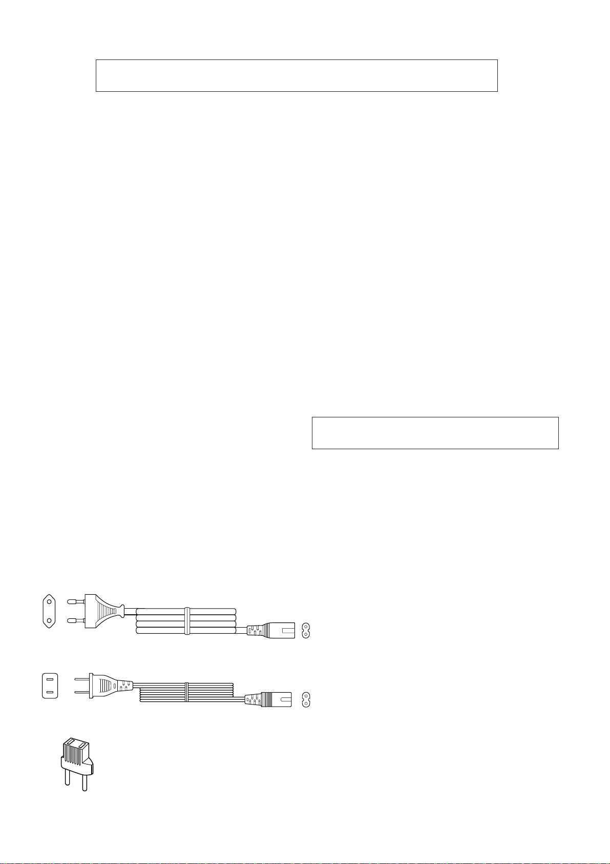
AC POWER SUPPLY CORD AND AC PLUG ADAPTOR
QACCE0007AW00
QACCA0001SJ00
QPLGA0253AFZZ
– 2 –
Page 3
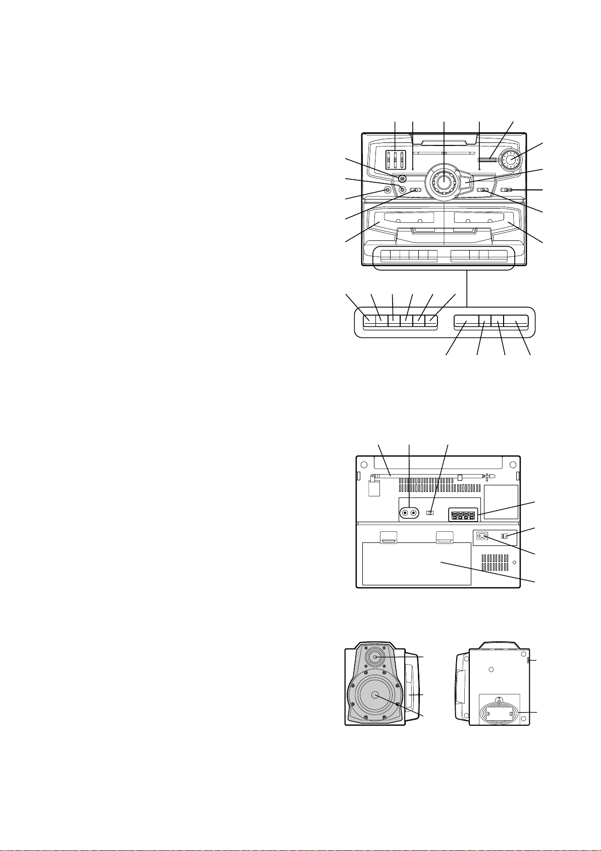
NAMES OF PARTS
11.
Graphic Equalizer Controls
12.
Power Indicator
13.
Volume Control
14.
FM Stereo Indicator
15.
Fine Tuning Control
16.
Built-in Microphone
17.
Mixing Microphone Socket
18.
Headphone Socket
19.
Function Selector Switch
10.
(TAPE 1) Cassette Compartment
11.
Tuning Control
12.
Extra Bass Switch
13.
Band Selector Switch
14.
Dubbing Speed/Built-in Microphone/FM Mode Switch
15.
(TAPE 2) Cassette Compartment
16.
(TAPE 1) Record Button
17.
(TAPE 1) Play Button
18.
(TAPE 1) Rewind Button
19.
(TAPE 1) Fast Forward Button
20.
(TAPE 1) Stop/Eject Button
21.
(TAPE 1) Pause Button
22.
(TAPE 2) Play Button
23.
(TAPE 2) Rewind Button
24.
(TAPE 2) Fast Forward Button
25.
(TAPE 2) Stop/Eject Button
6
7
8
9
10
16
17
12 4 5
18
3
21
2019
22
2423
WF-1000W
11
12
13
14
15
25
26.
FM/SW Telescopic Rod Aerial
27.
CD/Line Input Sockets
28.
Beat Cancel Switch
29.
Speaker Terminals
30.
AC Voltage Selector
31.
AC Power Input Socket
32.
Battery Compartment
33.
Tweeter
34.
Bass Reflex Duct
35.
Woofer
36.
Speaker Release Lever
37.
Speaker Wire
26
27 28
33
34
35
29
30
31
32
36
37
– 3 –
Page 4
WF-1000W
Tuner Gear
Stopper
Main PWB
Variable Capacitor
Dial Pointer
PWB
Make the minimum space.
Front Cabinet
Pointer Gear
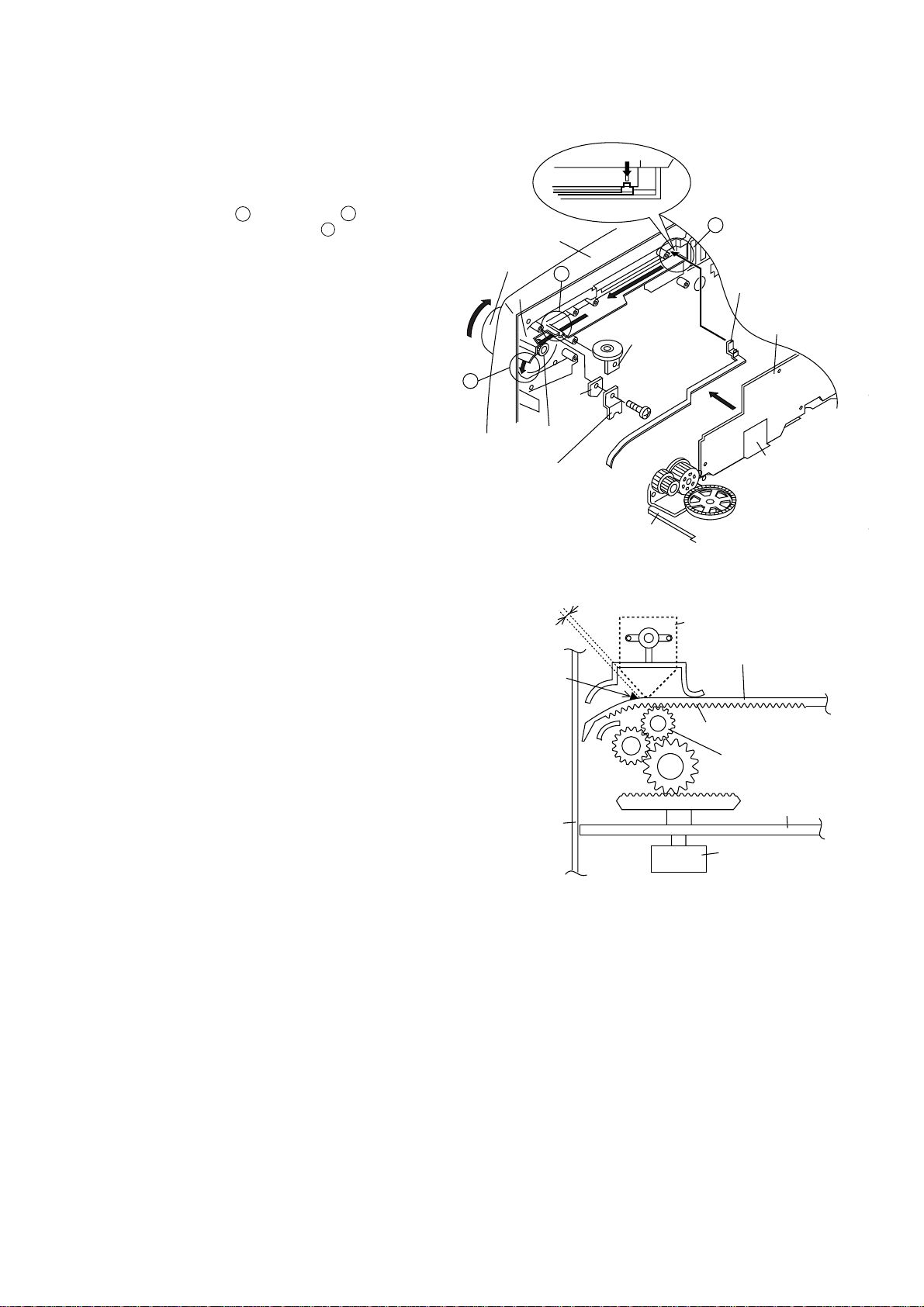
FITTING OF DIAL POINTER
1. Remove the Main PWB, the Graphic Equalizer PWB, the
Volume PWB and the Fine Tuning PWB. (See Figure 5-2
in the "Disassembly" on page 5.)
2. Remove the dial pointer guide and PWB.
3. Insert the dial pointer from , lead it under , hang it on
the tuner gear and then pass it through .
A
B
C
4. Replace the Main PWB, the Graphic Equalizer PWB, the
Volume PWB and the Fine Tuning PWB.
5. Rotate the tuning knob in the arrow direction until it stops.
(Set the tuner variable capacitor to "0" point (F-LOW
state).)
6. Adjust the dial pointer so that its stopper becomes the
Figure 4-2 position. (Adjust the engagement of the pointer
gear and the tuner gear to get the minimum space between
the PWB and the stopper.) This position is the "0" point.
7. Screw up the PWB and the dial pointer guide.
Front Cabinet
Tuning Knob
C
Dial Pointer Guide
(218)
Dial Pointer(211)
B
PWB
Tuner
Gear
"0" Point
Fine Tuning
PWB
Screw(601)
ø3x10mm
Main PWB
Figure 4-1
A
Dial Pointer(211)
Graphic Equalizer
PWB
Volume PWB
Figure 4-2
– 4 –
Page 5
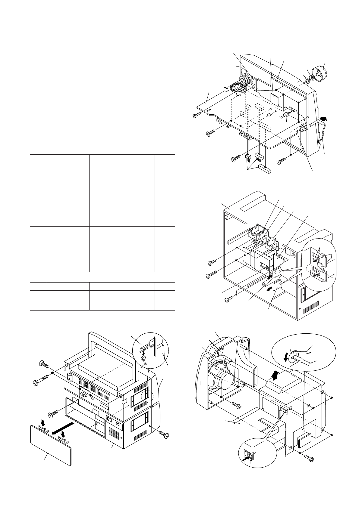
DISASSEMBLY
Rear Cabinet
(D1)x3
ø3x10mm
(D2)x2
ø4x16mm
(D4)x2
ø3x10mm
Power
Transformer
Voltage Selector
AC Socket
(D3)x1
Power
PWB
Terminal B
PWB
Terminal A
PWB
(D5)x2
(E3)x4
ø3x10mm
(E1)x5
ø4x16mm
Speaker Box
Main Unit
Speaker
Release
Lever
Speaker Cord
Holder
Speaker
Cord
Driver
Woofer
Tweeter
Front Panel
(E2)x1
Caution on Disassembly
Follow the below-mentioned notes when disassembling
the unit and reassembling it, to keep it safe and ensure
excellent performance:
1. Take cassette tape out of the unit.
2. Be sure to remove the power supply plug from the wall
outlet before starting to disassemble the unit and remove
the batteries from the unit.
3. Take off nylon bands or wire holders where they need
to be removed when disassembling the unit. After
servicing the unit, be sure to rearrange the leads where
they were before disassembling.
4. Take sufficient care on static electricity of integrated
circuits and other circuits when servicing.
MAIN UNIT
STEP REMOVAL PROCEDURE FIGURE
1 Front Cabinet/ 1. Battery Compartment Lid. 5-1
Rear Cabinet ................................. (A1)x1
2. Screw ................... (A2)x3
3. Screw ................... (A3)x4
4. Socket .................. (A4)x1
2 Main PWB/ 1. Knob.....................(B1)x1 5-2
Graphic Equalizer 2. Socket .................. (B2)x3
PWB/ 3. Screw................... (B3)x5
Volume PWB/ 4. Screw ................... (B4)x2
Fine Tuning PWB 5. Mic ....................... (B5)x1
3 Tape mechanism 1. Open the cassette holder. 5-2
2. Screw ................... (C1)x6
4 Power PWB/ 1. Screw ................... (D1)x3 5-3
Terminal A PWB/ 2. Screw ................... (D2)x2
Terminal B PWB 3. Bracket.................(D3)x1
4. Screw ................... (D4)x2
5. Hook.....................(D5)x2
Front Cabinet
Main PWB
(B4)x2
ø3x10mm
(C1)x4
ø3x10mm
Fine Tuning PWB
(B3)x5
ø3x10mm
(B2)x3
Volume
PWB
Figure 5-2
Graphic
Equalizer PWB
Washer
(B5)x1
(C1)x2
ø3x10mm
WF-1000W
(B1)x1
Nat
Open
Cassette
Holder
(Left/Right)
Tape
Mechanism
SPEAKER UNIT
STEP REMOVAL PROCEDURE FIGURE
1 Speaker 1. Screw ................... (E1)x5 5-4
2. Front Panel .......... (E2)x1
3. Screw ................... (E3)x4
Main PWB
(A2)x1
ø3x6mm
(A3)x4
ø3x20mm
(A2)x1
ø3x10mm
(A1)x1
Cabinet
Rear
(A4)x1
(A2)x1
ø3x6mm
Figure 5-1
Figure 5-3
Front
Cabinet
Figure 5-4
– 5 –
Page 6
WF-1000W
ADJUSTMENT
MECHANISM SECTION
• Driving Force Check
Torque Meter
Play: TW-2412 Tape 1: Over 60 g
Specified Value
Tape 2: Over 60 g
• Torque Check
Torque Meter
Play: TW-2111 30 to 70 g.cm 30 to 70 g.cm
Fast Forward: TW-2231 Over 55 g.cm Over 55 g.cm
Rewind: TW-2231 Over 55 g.cm Over 55 g.cm
Specified Value
Tape 1 Tape 2
• Head Azimuth
Test Tape
MTT-114 Headphones Socket
Instrument Connection
(Load resistance: 32 ohms)
• Tape Speed (Normal only)
Test Tape
MTT-111 Tape 1,2:VR102 3,000 ± 60 Hz Headphones
Adjustment
Point
Specified
Value
Instrument
Connection
Socket
(Loadresistance:
32 ohms)
DECK SECTION
• Bias Oscillation
• Beat Cancel Switch: C
Adjustment Point Specified value Instrument
L301 100 kHz + 4 kHz Pin 1 of CNS102
Specified Value
Beat Cancel A: 104 ± 4 kHz
B: 94 ± 4 kHz
C: 100 ± 4 kHz
• Playback Amplifier Sensitivity Check
Test tape
MTT-118 2.5 V ± 3 dB Speaker terminal
Specified value Instrument Connection
(Load resistance: 8 ohms)
Connection
TUNER SECTION
fL: Low-range frequency
fH: High-renge frequency
• FM IF/RF
Test Stage
FM IF L9 Input: FM Antenna
FM Detection L10 Output:Pin 9 of IC2
FM Band fL: L1 Input: Antenna
Coverage fH: TC1 Output: Headphone Socket
FM Tracking fL(88.0 MHz): L2 (Load resistance:
Specified Value/
Adjusting
Point
fH(108 MHz): TC2 32 ohms)
• AM IF/RF
Test Stage
AM IF L11
MW Band fL: L6
Coverage fH: TC3
MW Tracking fL(600 kHz): L3
SW1 Band fL(2.3 MHz): L7
Coverage fH(7.3 MHz): TC5
SW1 fL(2.6 MHz): L4
Tracking fH(6 MHz): TC6
SW2 Band fL(7.3 MHz): L8
Coverage fH(22 MHz): TC7
SW2 fL(8.5 MHz): L5
Tracking fH(19 MHz): TC8
Specified Value/
Adjusting
Point
fH(1,400 kHz):TC4
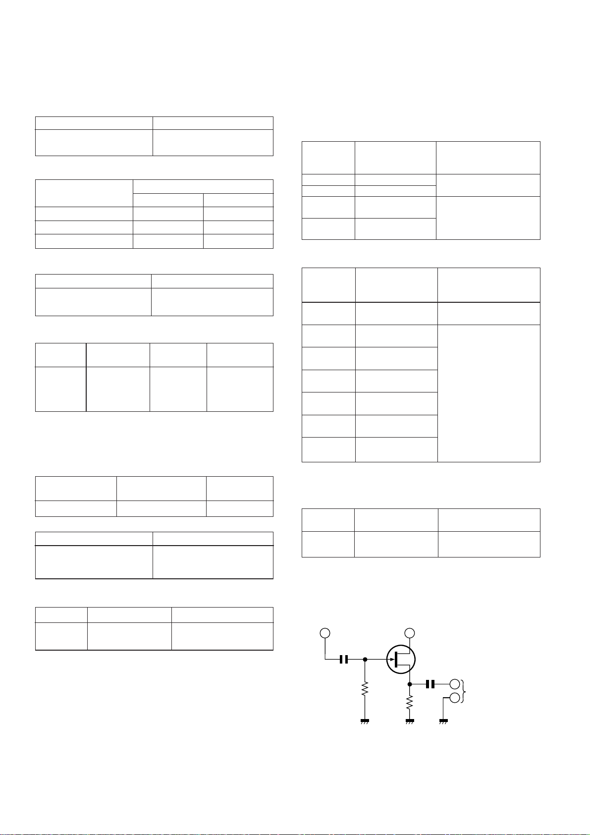
• VCO Frequency
Adjustment
Point
VR1 76 kHz ± 200 Hz Pin 13, Pin 21 and ground
Specified value Instrument Connection
Note:
After preparing the test circuit shown in Fig. 6, connect the Pin
13, Pin 21 and ground of the IC2 with the test circuit, and
measure the value.
Pin 13 of IC2
10 pF
1M ohm
Pin 21 of IC2
G
D
FET: 2SK212
(or Other 2SK Type FET.)
S
0.1 µF
10K ohm
Instrument
Connection
Instrument
Connection
Input: Antenna
Output: Pin 9 of IC2
Input: Antenna
Output: Headphone Socket
(Load resistance
32 ohms)
of IC2
TO FREQUENCY
COUNTER
– 6 –
Figure 6 VCO FREQUENCY TEST CIRCUIT
Page 7

WF-1000W
SW401
CF2
IC2
TC6
SW1
TC5
SW103
L7
TC7
L1
L2
L8
L6
L5
TC8
L9
L11
CF3
IC1
CF1
IC501
CNP103
IC502
VR102
VR1
L10
CNP501
SPEAKER TERMINALS
1
24
12
SW1
TRACKING fH
TC1
TC2
TC3
TC4
MW
TRACKING fH
MW BAND
COVERAGE fH
FM TRACKING
fH
FM BAND
COVERAGE
fH
fL
SW2
TRACKING
fH
fL
L4
L3
SW1
TRACKING fL
MW
TRACKING fL
FM
TRACKING fL
AM IF
FM IF
FM DETECTION
VCO
SW1 BAND
COVERAGE
fH
fL
SW2 BAND
COVERAGE
fH
fL
MW BAND
COVERAGE fL
TAPE SPEED
MAIN PWB
9
21
13
L301
SW102
BIAS OSCILLATION
Figure 7-1 ADJUSTMENT POINTS
NOTES ON SCHEMATIC DIAGRAM
• Resistor:
To differentiate the units of resistors, The symbol as K and
M are used: the symbol K means 1000 ohm and the symbol
M means 1000 kohm and the resistor without any symbol
is an ohm resistor. The resistor designated “Fusible” is a
fuse type resistor.
• Capacitor:
To indicate the unit of capacitor, a symbol P is used: this
symbol P means pico-farad and the unit of the capacitor
without such a symbol is microfarad. As to electrolytic
capacitor, the expression “capacitance/withstand voltage”
is used.
(CH),(RH),(UJ): Temperature compensation
(ML): Mylar type
(S): Styrol type
• The indicated voltage in each section is the one measured
by Digital Multimeter between such a section and the
chassis with no signal given.
• Schematic diagram and Wiring Side of P.W. Board for this
model are subject to change for improvement without prior
notice.
• Parts marked with “ ” ( ) are important for
maintaining the safety of the set. Be sure to replace these
parts with specified ones for maintaining the safety and
performance of the set.
– 7 –
REF. NO.
DESCRIPTION POSITION
SW1 BAND SELECTOR FM
SW101 RECORD/PLAYBACK PLAYBACK
SW102 BEAT CANCEL A
SW103 DUBBING SPEED/MIC/ MIC/FM MONO
SW401 X-BASS ON
SW501 FUNCTION SELECTOR CD/LINE
SW501A TAPE 2 MAIN OFF
FM MODE
SW502 TAPE 1 MAIN OFF
SW503 TAPE 2 PLAY OFF
SW601 VOLTAGE SELECTOR AC220-240V
FRONT
VIEW
E B C
KTA1271 Y
KTC3199 GR
333ID
KTC3203 Y
Figure 7-2 TYPES OF TRANSISTOR AND LED
FRONT
VIEW
Page 8

WF-1000W
A
B
C
D
E
MIC151
BUILT-IN
MICROPHONE
CONDENSER
MIC
F
L-CH
R-CH
RECORD/
PLAYBACK HEAD
L-CH
R-CH
G
ERASE HEAD
H
FM/SW
ROD
ANTENNA
L-CH
SO351
CD/LINE
R-CH
J151
MIC
IN
TAPE2
PLAYBACK HEAD
TAPE1
FM SIGNAL
FM BAND PASS
FILTER
1
SW1-A
BAND
SELECTOR
D1
DS1SS133
SW1-B
BAND
SELECTOR
SW2
VC4
SW1-C
BAND
SELECTOR
SW1
SW2
C153
0.01
(ML)
C151
0.33/50
CNP101
CNS101
1
1
2
2
3
3
1
1
2
2
3
3
4
4
CNS102
CNP102
SW102
BEAT
CANCEL
C307
150P
CF1
2
FM
MW
SW1
SW2
FM
MW
SW1
FM
MW
R351
47K
R352
47K
R151
2.2K
C131
120P
C133
C
B
C306
390P
MW/SW1/SW2 SIGNAL
RF AMP
3
0.7V
1
1.5V 5.8V
C5
0.001
FM
TRACKING
C4
24P
L2
(CH)
R1
10
C6
0.0047
C7
0.0047
TC4
TC6
L3,L4: MW/SW1
BAR ANTENNA
TC8
SW2 ANTENNA
R353
2.2K
R354
2.2K
R162
47K
Q151
KTC3199 GR
C155
MIC AMP.
1/50
0.6V
R153
0V
220K
R152
560
C154
10/16
C152
10/16
R135
15K
L103
22mH
P
R R P
R
SW101-D
SW101-C
SW101-B
L104
22mH
SW101-A
R
P
L301
BIAS OSC.
C304
0.022
R136
15K
150P
C134
150P
C132
120P
C305
0.0015
(ML)
A
IC1 TA7358AP
FM FRONT END
IC1 TA7358AP
MIX
1.4V0V5.8V
432
C2
5P(CH)
TC2
VC2
C8
0.022
L3
MW
L4
SW1
L5
R160
4.7K
3.2V
1.3V
0.7V
1.3V
Q152
KTC3199 GR
MIC AMP.
R161
330
R154
560
SW101
RECORD/
PLAYBACK
P
R306
47
C303
0.0056
(ML)
9
5.8V
D2
SW1
SW2
C15
0.022
R156
1K
+B
C101
470P
C102
470P
R305
27K
C302
0.0022
(ML)
6
FM OSC.
DS1SS133
C9
0.022
FM
MW
FINE
TUNING
C157
1/50
R155
39K
CH1/A
Q301
KTC3203 Y
(0.7V)
( ): RECORD
R2
33
L1
( ): RECORD
C105
330P
C106
330P
C104
820P
MAIN PWB-A1/VOLUME PWB-A3/FINE TUNING PWB-A4
PLAYBACK SIGNAL
TC3
C20
1500P
(P.P)
C27
0.0047
(P.P)
R167
10K
0V(0V)
R169
10K
LINE AMP.
Q156
KTC3199 GR
20
PRE
OUT
PRE
OUT
5
C114
4.7/50
+B
R
P
C13
0.022
R5
100
1
2
CF2
10.7MHz
FM IF
D151
DS1SS133
R168
10K
R121
19
A/B
MIX
OUT
6
R7
820K
C22
0.022
C18
10/16
24
AM
OSC
FM IF
IN
3
C25
0.022
C21
5P
(UJ)
TC5
TC7
SW103
DUBBING SPEED/
MIC
HIGH
NORMAL
MIC
10K
18
VCC
GND1
7
C129
22/16
R122
10K
R123
10K
R124
10K
R301
100
IC101 : VOLTAGE
PIN
PLAY
REC
PIN
PLAY
REC
R4
7
330K
C12
5.0V
OSC
8
5.7V
C11
22P
(CH)
SW1-D
BAND SELECTOR
SW1-E
BAND
SELECTOR
C14
5P(CH)
TC9
C156
47/16
C103
820P
CH1/B
BIAS OSC.
(0.1V)
R304
3P(CH)
5
C10
15P(CH)
TC1
VC1
R3
47
L9
FM IF
C19
300P
(P.P)
FM
MW
SW1
SW2
VC3
R166
560
MIC AMP.
0V(3.4V)
R157
47K
R173
10K
2324
C110
10/16
10
0V(0V)
Q153
KTC3199 GR
OTHER:NORMAL
( ): HIGH
(0V)
(0.6V)
0V
R103
C113
56K
4.7/50
R101
56
R109
C111
4.7K
0.033
(ML)
R107
5.6K
C109
10/16
R105
180K
C107
330P
22
21
NFCH2/B CH2/A
MATAL
OUT
IC101
RECORD/PLAYBACK AMP. TA8189N
MATAL
NF
OUT
4 3 2 1
C108
330P
R106
180K
R108
5.6K
C112
0.033
R110
(ML)
4.7K
R104
56K
R102
56
R302
100
(5.5V)
SW101-E
RECORD/
C301
100/16
PLAYBACK
R303
100
RECORD SIGNAL
+B
C121
330P
C122
330P
R10
47
C158
4.7/50
R117
330K
REC IN
R120
390
R118
330K
1.3V
1.3V
1.3V
20
FM DET
AGC
4
C29
22/16
FM
MW
SW1
SW2
SW1-F
BAND
SELECTOR
R11
47
D153
DS1SS133
R119
390
14
REC IN
11
1.3V
1.3V
2.1V
2.1V
R8
3.9K
AM OUT
AM IF
1
2
FM
MW
SW1
SW2
C43
220P
D154
D158
DS1SS133
C119
0.015
(ML)
C123
0.0015
13
ALC
GND
12
C124
0.0015
C120
0.015
(ML)
C31
0.0047
(ML)
R9
12K
C32
0.0082
(ML)
19
IF AD
GND
5
3
CF3
455kHz
AM IF
SW1-G
BAND
SELECTOR
D156
DS1SS133
+B
C160
22/16
R125
1M
1.4V
1.4V
1.4V
1.5V
18
AM IN
6
7
C30
0.022
+B
C159
4.7/50
DS1SS133
L101
2.7mH
C125
4.7/50
C130
22/16
C126
4.7/50
L102
2.7mH
1.4V
1.4V0V0V0V0V
5.2V
5.2V
C23
220/10
FM
DETECTION
C17
0.022
L10
21
23
22
+B
AM RF
STB
IC2
FM/AM IF MPX. LA1805
AM MIX
3 2 1
L11
C24
0.022
AM IF
L6
MW OSC.
L7
SW1 OSC.
L8
SW2 OSC.
C26
0.022
SW101-F
RECORD/PLAYBACK
R
P
R172
10K
SW103-A
D152
DS1SS133
R100
D101
150
DS1SS133
R115
2.2K
C115
C128
4.7/50
2.2/50
C127
1000/10
C117
10/16
R113
180K
16
15
17
REC
REC NF
OUT
REC
REC
M/N
NF
OUT
10
8
9
R114
180K
C118
C116
10/16
4.7/50
R116
2.2K
123456789101112
0V0V0V0V1.3V
13 14 15 16 17 18 19 20 21 22 23 24
0.9V
0.9V0V0V
17 16
IF AD
DET OUT
8
C37
0.012
(ML)
R12
1K
R13
100
FM
MW
SW1
SW2
R177
1K
C135
0.0027
(ML)
R127
47K
R128
47K
2.1V0V1.4V
MPX
IN
D155
DS1SS133
R131
4.7K
R132
4.7K
1.4V
FM STEREO
C34
470P
C33
3.3/50
15 14 13 12
L-CH
9
R15
10K
SW1-H
BAND
SELECTOR
D162
DS1SS133
D159
DS1SS133
R111
22K
R129
22K
R130
22K
C136
0.0027
(ML)
R112
22K
2.1V
2.1V
1.3V
1.3V
SW103-B
FM MODE
R14
100K
C35
3.3/50
MO/ST
C38
0.012
(ML)
C39
1/50
R17
2.7K
C42
0.022
R133
82K
R134
82K
+B
1.3V
1.3V0V0V0V0V
1.3V
1.3V0V0V0V0V
R-CH
R174
22K
10
FM MONO
C36
1500P
(P.P)
VCO
AM/FM
11
C40
1/50
R16
10K
VR1
10K(B)
VCO
NC
C41
1/50
R20
10
R18
2.7K
CD/LINE
TUNER
TAPE
SW501-A
FUNCTION
SELECTOR
CD/LINE
TUNER
TAPE
CD/LINE
TUNER
R19
15K
TP1
VCO
76kHz
+B
+B
SW501-B
FUNCTION
SELECTOR
TAPE
L-CH
R-CH
SW501-C
FUNCTION
SELECTOR
R181
1K
+B
R182
1K
C181
1/50
R511
10K
C182
1/50
R183
330K
R184
330K
+B
• NOTES ON SCHEMATIC DIAGRAM can be found on page 7.
1
2
34 5
Figure 8 SCHEMATIC DIAGRAM (1/2)
– 8 –
6
Page 9

WF-1000W
IC2 : VOLTAGE
fH
fH
Q181
2V
KTC3199 GR
0.2V
R185
220
R186
220
0.2V
2V
fL
fH
fL
GRAPHIC
EQUALIZER
R188
3.9K
C186
1/50
R180
560
+B
TC6
L4
TC8
L5
SW1 BAND
COVERAGE
SW2 BAND
COVERAGE
C185
1/50
R187
3.9K
C180
100/16
MW
fH
TC5
TRACKING
fL
L7
fH
TC7
MW BAND
COVERAGE
fL
L8
GRAPHIC EQUALIZER PWB-A2
L-CH
R-CH
GND
+B
R-CH
L-CH
SW1
TRACKING
SW2
TRACKING
R183
330K
C181
0.8V
1/50
C183
220P
C184
220P
C182
1/50
0.8V
R184
182
330K
Q182
KTC3199 GR
GRAPHIC
EQUALIZER
+B
fH
TC4
FM
TRACKING
fL
L3
fH
TC3
FM BAND
COVERAGE
fL
L6
R203
2.2K
R205
10K
R201
1K
+B
R200
330
C200
220/16
R202
C202
1K
4.7/50
R204
R206
2.2K
10K
TC2
L2
TC1
L1
R211
1K
19
2V
3.5V
2V
18
20
R212
1K
PIN
FM
MW/SW1/SW2
PIN
FM
MW/SW1/SW2
R209
100K
C217
0.47/50
C221
4.7/50
C219
0.039(ML)
15
17
13
5.1V
4.5V
3.5V
4.5V
5.1V
16
14
C208
470P
C212
C206
0.01
(ML)
VR205-B
VR204-B
100K(B)
100K(B)
(10kHz)
(2kHz)
GRAPHIC EQUALIZER
VR203-A
100K(B)
(500Hz)
C215
5.1V
12
0.0015(ML)
fL
fH
fL
C203
1/50
C201
4.7/50
23
21
2.7V
5.5V
IC201 GRAPHIC EQUALIZER BA3822LS
2.7V
0V
24
22
C222
4.7/50
C204
1/50
123456789101112
1.6V
1.6V
5.8V
0.2V
1.6V
10.7V
1.7V
1.7V
6.5V
1.4V
13 14 15 16 17 18 19 20 21 22 23 24
1.1V0V2.1V
1.9V1V1.8V
GRAPHIC EQUALIZER
VR205-A
VR204-A
100K(B)
100K(B)
(10kHz)
(2kHz)
C209
C213
0.082
0.33/50
(ML)
C207
C211
0.0015(ML)
9
5.1V
5.1V
8
C216
0.0056(ML)
7
4.5V
6
C214
0.33/50
BI1
5
4.5V
C220
1
470P
5.1V
5.1V
4 3 2
0.039(ML)
R210
100K
1
0.0056(ML)
11
5.1V
4.5V
4.5V
10
C210
0.082
(ML)
VR203-B
100K(B)
(500Hz)
1.7V0V0V
1.8V
1.6V
1.8V
1.7V
C205
0.01
(ML)
1
4.5V
4.5V
C218
0.47/50
STEREO
33
1
3
2
3
1
2
LED1
333ID
1.6V
1.6V
BI2
10.7V0V0V
0.4V
1.1V
+B
GND
5.8V
6.3V
2.4V
2.4V
5.8V
6.3V
R518
1K
LED502
333ID
POWER
2.4V
2.4V
0.5V
1.7V
5.1V
6.4V
1.6V
1.7V
0.9V
0.9V
1.4V
1.6V
R511
10K
+B
+B
Q501
KTC3203 Y
7.4V
C502
8V
0.022
VOLTAGE
REGULATOR
C503
0.022
Q502~Q504:
TAPE SPEED CONTROL
OTHER:NORMAL
( ): HIGH
Q502
KTC3199 GR
0V(0.7V)
R512
0V(0V)
10K
12V
R503
100
C504
100/16
DZ501
DZ8.2BSB
0.7V(0V)
C505
100/16
R504
680
C507
0.022
R513
10K
Q503
KTC3199 GR
0V(7.8V)
0.7V(0V)
0V(0V)
C511
0.022
IC501
VOLTAGE REGULATOR
KIA7812P
12V
IC501
OUT IN
1
GND
C506
2
0.022
L501
47µH
C508
100/16
Q504
KTA1271 Y
7.8V
(7.9V)
R514
100K
VR102
C512
470
100/16
TAPE
SPEED
SW401
X-BASS
ON
OFF
R415
VOLUME
1K
C413
0.001
(ML)
C415
R417
0.15
22K
(ML)
R419
3.3K
R420
3.3K
C416
R418
0.15
22K
(ML)
C414
0.001
(ML)
R416
1K
15V
3
C513
0V
1/50
SW501-D
FUNCTION
SELECTOR
CD/LINE
TUNER
R516
3.9K
OUT
TAPE
15V
IC502
3
IN
GND
C514
2
0V
1/50
R517
56K
1
2
3
4
5
6
7
8
CNP103
IC502
9V
C509
0.022
8.4V(8.4V)
8.4V(6.2V)
VOLTAGE
REGULATOR
KIA7809P
1
R515
47
CNS103
1
2
3
4
5
6
7
8
VR401-A
50K(B)
VR401-B
50K(B)
VOLUME
R425
1K
C418
22/16
R429
100K
R427
4.7K
R428
4.7K
R426
1K
0.7V
0.7V
C510
3300/25
+
-
B
A
C419
4.7/50
0V
0V
0V
0V
C420
4.7/50
M
SW502
TAPE1 MAIN
SW501A
TAPE2 MAIN
SW503
TAPE2 PLAY
Q403
KTC3199 GR
POWER MUTE
Q404
KTC3199 GR
POWER MUTE
M501
TAPE
MOTOR
R441
15K
L-CH
R442
1
2
2
6
C423
10/16
3
C424
47/25
1
15K
R-CH
4
6.5V
R431
27K
D401
DS1SS133
1
2
CNP601
CNS601
C652
0.022
C653
0.022
TERMINAL B
PWB-A6
IC402
LA4663
POWER AMP.
+OUT1
0V
0V
0V
14.2V
0V
14
6.9V
13
0V
-OUT1
12
6.9V
IC402
+OUT2
6.9V
0V
10
-OUT2
11
6.9V
8
5
7
15V
15V
C433
0.022
+B
POWER PWB-A7
D651
TS4B03GM
BATTERYES DC15V
["D" SIZE(UM/SUM-1,
R20 or HP2)
BATTERY x 10]
9
R433
C425
2.2
0.1(ML)
R435
C427
2.2
0.1
(ML)
C426
0.1(ML)
C428
0.1
(ML)
F601
T4A L
250V
C651
0.022
C654
0.022
TERMINAL A
PWB-A5
R434
2.2
R436
2.2
C430
10/16
CNP501
SPEAKER
+
L-CH
R-CH
+
C429
J401
10/16
HEADPHONES
R437
120
R438
120
SW601
VOLTAGE SELECTOR
AC110V-127V
AC220V-240V
T601
POWER
TRANSFORMER
TERMINALS
SP403
TWEETER
SP404
TWEETER
SO601
AC POWER
INLET
SOCKET
AC110-127V/
AC220-240V,
50/60Hz
SO601
L-CH
SP401
WOOFER
8 Ohm
SP402
WOOFER
8 Ohm
R-CH
78 9101112
Figure 9 SCHEMATIC DIAGRAM (2/2)
– 9 –
Page 10

WF-1000W
M501
TAPE
MOTOR
SW503
TAPE2
PLAY
SW501A
TAPE2
MAIN
SW502
TAPE1
MAIN
AB
+-
BR
GY
GY
RD
OR
YL
GR
BL
VL
GR
1
CNS103
2
3
4
5
6
7
8
WH
CNS102
CNS101
RD
RD
WH
BK
BK
2
3
4
1
2
3
1
ERASE
HERAD
RD
WH
BK
GY
GY
RECORD/PLAYBACK
HEAD
TAPE 2
TAPE 1
BR
COLOR TABLE
RD(R)
OR
YL
GR
BL
VL
GY
WH(W)
BK
PK
BROWN
RED
ORANGE
YELLOW
GREEN
BLUE
VIOLET
GRAY
WHITE
BLACK
PINK
FM/SW ROD ANTENNA (253)
C217
VR203
VR204
VR205
C206
C208
C210
C218
C214
C220
C216
C212
IC201
C200
C213
C209
C211
C219
R200
C201
C202
R202
C221
C205
C207
C203
C204
R204
R205
R203
C222
LED502
R206
R201
C215
R518
C414
C416
R420
R419
C413
C415
LED1
FW1
VR401
VOLUME
R212
TC9
FINE TUNING
PWB-A4
VOLUME
PWB-A3
GRAPHIC
EQUALIZER
PWB-A2
BK
BK
FW2
2
1
5
10
15
20
24
23
A
B
A
B
A
B
5
1
A
B
(249)
TC9
FINE TUNING
VR203
500Hz
GRAPHIC
EQUALIZER
VR204
2kHz
VR205
10kHz
RD
WH
BK
PLAYBACK HEAD
R209
R210
R211
BR
RD
YL
OR
GR
BL
BR
RD
A
B
C
D
E
F
G
H
1
2
34 5
6
Figure 10 WIRING SIDE OF P.W.BOARD (1/3)
– 10 –
Page 11

MIC151
BUILT-IN
MICROPHONE
WH
BK
J151
MIC
IN
TAPE
RADIO
SW501
CD/LINE
FUNCTION
SELECTOR
GR
SW401
X-BASS
OFF ON
OR
SW103
DUBBING SPEED/
MIC/FM MODE
FM
MONO
NORMAL
FM
STEREO
BAND
SELECTOR
J401
HEADPHONE
C151
MIC
HIGH
SW1
FM
MW
SW1
SW2
R151
R152
SW501
C
BL
YL
SW103
A
C153
R10
WH
C152
BK
BD
A
B
H
G
B
SW1
A
R437
R438
C155
R415
C429
R153
R418
R416
C30
E
F
C
D
C430
C154
R154
C159
SW401
1
BI2
C19
C42
C156
R161
R417
C27
E
C
B
R177
C20
R156
Q151
C14
R155
1
L7
TC6
C157
E
C
B
Q152
R162
3
3
Q153
R157
E
C
B
R160
R166
C158
D151
R168
SW101
RECORD/
PLAYBACK
BI1
TC5
C44
R11
TC4
TC3
BL
R169
D401
R301
BK
C26
VC4
VC3
D153
R167
C134
WH
CNP102
R13
TC7
L8
C4
VC2
VC1
C428
R436
C426
D154
R186
R180
R187
R181
PLAYBACK
RECORD
SW101
A
B
C
C133
4
3
D
2
1
E
F
L2
C11
R434
D162
R431
R182
R188
C180
C21
C6
TC2
TC1
CNP601
2 1
C425
R185
C132
CNP101
C131
L103
R303
L6
L1
R183
3
2
1
R1
C12
C7
1
C110
C102
C5
C10
C427
C184
C183
E C B
L104
C104
C101
IC1
R2
TC8
14
C182
E C B
C181
C103
C109
1
2
3
1
2
3
4
5
6
7
8
9
R433
R435
12
13
FW1
R104
C106
R102
R101
C105
R4
11
R184
R130
C107
R103
CF1
10
Q182
Q181
R511
C112
C111
R20
C2
C8
C9
L5
9
C423
5
R129
C108
R109
R172
C13
C433
IC402
8
7
C186
C185
R133
R124
R110
R136
R108
R106
5201
IC101
R105
R107
D152
R14
D2
6
R442
C114
C41
C25
L9
4
5
R426
R112
R114
C37
D1
3
R425
R134
C116
R122
10
1524
R113
C115
R135
B
Q156
L11
C15
2
C420
C129
C118
12
13
CE
R12
C38
1
D156
R123
C160
R121
R15
R3
C424
Q404
E C B
R441
E C B
Q403
C419
D155
C418
D158
1
2
3
4
C512
5
6
CNP103
7
8
C514
C506
C513
C120
L102
R120
C136
R128
R116
R118
C122
C128
C127
R125
C130
C121
R117
R115
R119
C117
R18
R17
R16
C22
C23
C39
C40
12
10
CF3
1
IC2
2
520
3
CF2
1
3
2
1
C24
C43
R5
C510
R429
IC502
IC501
C126
C124
C113
C125
R131
R173
C36
24
C17
C29
R427
1
2
3
1
2
3
R132
R127
D101
C123
13
15
C18
R428
R19
R8
R512
R174
R111
C135
C119
R516
L501
D159
C33
C32
L10
C508
E
C
Q502
B
C505
L101
VR1
C35
C31
C509
R9
R515
R517
E C B
R513
B C E
R504
R100
C303
C34
C511
E C B
Q301
R302
BK
VCO
R7
R503
Q501
C302
R351
VR102
Q504
R514
Q503
C507
DZ501
B C E
FROM POWER PWB
TAPE
SPEED
C504
C503
C502
R304
C307
R305
R306
C304
L301
WH
C305
R354
R353
R352
C301
C306
SW102
CNS601
P12 5-F
C
B
A
WF-1000W
L-CH
CNP501
SPEAKER
TERMINALS
R-CH
C
SW102
B
BEAT
CANCEL
A
L-CH
SO351
CD/LINE
INPUT
R-CH
MAIN PWB-A1
L4
SW1
MW/SW1 BAR ANTENNA
78 9101112
MW
L3
Figure 11 WIRING SIDE OF P.W.BOARD (2/3)
– 11 –
Page 12

WF-1000W
A
SW601
VOLTAGE SELECTOR
AC220V-240V AC110V-127V
B
OR
SO601
AC POWER INLET
SOCKET
AC110V-127V/
AC220V-240V,
50/60Hz
(250)
TERMINAL A
PWB-A5
(251)
BATTERYS
DC15V
["D" SIZE (UM / SUM-1,
R20 or HP2) battery x 10]
C
BK
RD
(251)
T601
POWER
TRANSFORMER
D
BL
WH
(237)
RD
TERMINAL B
PWB-A6
E
F
COLOR TABLE
WH
OR
BK
RD
BK
CNS601
1
2
TO MAIN PWB
CNP601
P11 12-A
BR
BROWN
RD(R)
OR
G
YL
GR
BL
VL
GY
WH(W)
H
BK
PK
1
RED
ORANGE
YELLOW
GREEN
BLUE
VIOLET
GRAY
WHITE
BLACK
PINK
F601
T4A L 250V
2
C653
C654
D651
POWER
PWB-A7
C652
C651
34 5
6
Figure 12 WIRING SIDE OF P.W.BOARD (3/3)
– 12 –
Page 13

PARTS GUIDE
WF-1000W
“HOW TO ORDER REPLACEMENT PARTS”
To have your order filled promptly and correctly, please furnish the
following information.
1. MODEL NUMBER 2. REF. No.
3. PART NO. 4. DESCRIPTION
MARK: SPARE PARTS-DELIVERY SECTION
Explanation of capacitors/resistors parts codes
Capacitors
VCC ....................... Ceramic type
VCK........................ Ceramic type
VCT........................ Semiconductor type
VC • • MF ............... Cylindrical type (without lead wire)
VC • • MN............... Cylindrical type (without lead wire)
VC • • TV................ Square type (without lead wire)
VC • • TQ ............... Square type (without lead wire)
VC • • CY ............... Square type (without lead wire)
VC • • CZ ............... Square type (without lead wire)
VC • • • • • • • • • J .. The 13th character represents capacity difference.
("J" ±5%, "K" ±10%, "M" ±20%, "N" ±30%,
"C" ±0.25 pF, "D" ±0.5 pF, "Z" +80-20%.)
If there are no indications for the electrolytic capacitors, error is ±20%.
MODEL
WF-1000W(BK)
WF-1000W(S)
For U.S.A. only
Contact your nearest SHARP Parts Distributor to order.
For location of SHARP Parts Distributor,
Please call Toll-Free;
1-800-BE-SHARP
Resistors
VRD ....................... Carbon-film type
VRS........................ Carbon-film type
VRN ....................... Metal-film type
VR • • MF ............... Cylindrical type (without lead wire)
VR • • MN............... Cylindrical type (without lead wire)
VR • • TV................ Square type (without lead wire)
VR • • TQ ............... Square type (without lead wire)
VR • • CY ............... Square type (without lead wire)
VR • • CZ ............... Square type (without lead wire)
VR • • • • • • • • • J .. The 13th character represents error.
("J" ±5%, "F" ±1%, "D" ±0.5%.)
If there are no indications for other parts, the resistors are ±5%
carbon-film type.
NOTE:
Parts marked with “ ” are important for maintaining the safety of the set.
Be sure to replace parts with specified ones for maintaining the safety and performance of the set.
Page 14

WF-1000W
PARTS CODE NO. PARTS CODE
PRICE
RANK
DESCRIPTIONNO.
INTEGRATED CIRCUITS
IC1 VHITA7358AP-1 J AG FM Front End,TA7358AP
IC2 VHILA1805//-1 J AM FM/AM IF MPX.,LA1805
IC101 VHITA8189N/-1 J AM Record/Playback Amp.,TA8189N
IC201 VHIBA3822LS-1 J Graphic Equalizer,BA3822LS
IC402 VHILA4663//-1 J Power Amp.,LA4663
IC501 VHIKIA7812P-1 J AE Voltage Regulator,KIA7812P
IC502 VHIKIA7809P-1 J Voltage Regulator,KIA7809P
TRANSISTORS
Q151~153 VSKTC3199GR-1 J AB Silicon,NPN,KTC3199 GR
Q156 VSKTC3199GR-1 J AB Silicon,NPN,KTC3199 GR
Q181,182 VSKTC3199GR-1 J AB Silicon,NPN,KTC3199 GR
Q301 VSKTC3203Y/-1 J AC Silicon,NPN,KTC3203 Y
Q403,404 VSKTC3199GR-1 J AB Silicon,NPN,KTC3199 GR
Q501 VSKTC3203Y/-1 J AC Silicon,NPN,KTC3203 Y
Q502,503 VSKTC3199GR-1 J AB Silicon,NPN,KTC3199 GR
Q504 VSKTA1271Y/-1 J AC Silicon,PNP,KTA1271 Y
DIODES
D1,2 VHDDS1SS133-1 J AB Silicon,DS1SS133
D101 VHDDS1SS133-1 J AB Silicon,DS1SS133
D151~156 VHDDS1SS133-1 J AB Silicon,DS1SS133
D158,159 VHDDS1SS133-1 J AB Silicon,DS1SS133
D162 VHDDS1SS133-1 J AB Silicon,DS1SS133
D401 VHDDS1SS133-1 J AB Silicon,DS1SS133
! D651 VHDTS4B03GM-1 J AK Silicon,TS4B03GM
DZ501 VHEDZ8R2BSB-1 J AB Zener,8.2V,DZ8.2BSB
LED1 VHP333ID///-1 J LED,Red,333ID
LED502 VHP333ID///-1 J LED,Red,333ID
FILTERS
CF1 RFILR0008AWZZ J AE FM Band Pass Filter
CF2 RFILF0106AFZZ J AC FM IF,10.7 MHz
CF3 RFILA0057AFZZ J AD AM IF,455 kHz
TRANSFORMER
! T601 RTRNP0001BGZZ J Power
COILS
L1 RCILB0001BGZZ J FM Oscillation
L2 RCILR0001BGZZ J FM Tracking
L3,4 RCILA0001BGZZ J MW/SW1 Bar Antenna
L5 RCILA0003BGZZ J SW2 Antenna
L6 RCILB0002BGZZ J MW Oscillation
L7 RCILB0003BGZZ J SW1 Oscillation
L8 RCILB0004BGZZ J SW2 Oscillation
L9 RCILI0002BGZZ J FM IF
L10 RCILI0003BGZZ J FM Detection
L11 RCILI0001BGZZ J AM IF
L101,102 VP-MK272K0000 J 2.7 mH,Choke
L103,104 VP-MK223K0000 J 22 mH,Choke
L301 RCILB0005BGZZ J Bias Oscillation
L501 VP-MK470K0000 J AB 47 µH,Choke
VARIABLE RESISTORS
VR1 RVR-M0026AWZZ J AC 10 kohm (B),Semi-VR [VCO]
VR102 RVR-M0018AWZZ J 470 ohms (B),Semi-VR
VR203~205 RVR-Q0001BGZZ J 100 kohm (B)×2
VR401 RVR-B0001BGZZ J 50 kohms (B)×2 [Volume]
[Tape Speed]
[Graphic Equalizer]
VARIABLE CAPACITORS
TC5,6 RTO-H1003SJZZ J AG Trimmer,5 pF
TC7,8 RTO-H1001BGZZ J Trimmer,10 pF
TC9 RVC-Z0001BGZZ J Fine Tuning
VC1~4 RVC-R0001BGZZ J Variable Capacitance with
Trimmer (TC1~4)
PRICE
RANK
DESCRIPTION
CAPACITORS
C2 VCCCPU1HH5R0J J AA 5 pF (CH),50V
C4 VCCCPU1HH240J J AA 24 pF (CH),50V
C5 VCKYPA1HB102K J AA 0.001 µF,50V
C6,7 VCKYPA1HB472K J AB 0.0047 µF,50V
C8,9 VCKZPA1HF223Z J AA 0.022 µF,50V
C10 VCCCPU1HH150J J AA 15 pF (CH),50V
C11 VCCCPU1HH220J J AA 22 pF (CH),50V
C12 VCCCPU1HH3R0J J AA 3 pF (CH),50V
C13 VCKZPA1HF223Z J AA 0.022 µF,50V
C14 VCCCPU1HH5R0J J AA 5 pF (CH),50V
C15 VCKZPA1HF223Z J AA 0.022 µF,50V
C17 VCKZPA1HF223Z J AA 0.022 µF,50V
C18 RC-GZA106AF1C J AB 10 µF,16V,Electrolytic
C19 VCQPKV2AA301J J 300 pF,100V,Polypropylene
C20 VCQPKV2AA152J J 1500 pF,100V,Polypropylene
C21 VCCUPA1HH5R0C J 5 pF (UJ),50V
C22 VCKZPA1HF223Z J AA 0.022 µF,50V
C23 RC-GZA227AF1A J AB 220 µF,10V,Electrolytic
C24~26 VCKZPA1HF223Z J AA 0.022 µF,50V
C27 VCQPKV2AA472J J AB 0.0047 µF,100V,Polypropylene
C29 RC-GZA226AF1C J AB 22 µF,16V,Electrolytic
C30 VCKZPA1HF223Z J AA 0.022 µF,50V
C31 VCQYKA1HM472K J AB 0.0047 µF,50V,Mylar
C32 VCQYKA1HM822K J AA 0.0082 µF,50V,Mylar
C33 RC-GZA335AF1H J AB 3.3 µF,50V,Electrolytic
C34 VCKYPA1HB471K J AA 470 pF,50V
C35 RC-GZA335AF1H J AB 3.3 µF,50V,Electrolytic
C36 VCQPKV2AA152J J 1500 pF,100V,Polypropylene
C37,38 VCQYKA1HM123K J AA 0.012 µF,50V,Mylar
C39~41 RC-GZA105AF1H J AB 1 µF,50V,Electrolytic
C42 VCKZPA1HF223Z J AA 0.022 µF,50V
C43 VCKYPA1HB221K J AA 220 pF,50V
C101,102 VCKYPA1HB471K J AA 470 pF,50V
C103,104 VCKYPA1HB821K J AA 820 pF,50V
C105~108 VCKYPA1HB331K J AA 330 pF,50V
C109,110 RC-GZA106AF1C J AB 10 µF,16V,Electrolytic
C111,112 VCQYKA1HM333K J AB 0.033 µF,50V,Mylar
C113~116 RC-GZA475AF1H J AB 4.7 µF,50V,Electrolytic
C117,118 RC-GZA106AF1C J AB 10 µF,16V,Electrolytic
C119,120 VCQYKA1HM153K J AB 0.015 µF,50V,Mylar
C121,122 VCKYPA1HB331K J AA 330 pF,50V
C123,124 VCKYPA1HB152K J AA 0.0015 µF,50V
C125,126 RC-GZA475AF1H J AB 4.7 µF,50V,Electrolytic
C127 RC-GZA108AF1A J AD 1000 µF,10V,Electrolytic
C128 RC-GZA225AF1H J AB 2.2 µF,50V,Electrolytic
C129,130 RC-GZA226AF1C J AB 22 µF,16V,Electrolytic
C131,132 VCKYPA1HB121K J AA 120 pF,50V
C133,134 VCKYPA1HB151K J AA 150 pF,50V
C135,136 VCQYKA1HM272K J AA 0.0027 µF,50V,Mylar
C151 RC-GZA334AF1H J AA 0.33 µF,50V,Electrolytic
C152 RC-GZA106AF1C J AB 10 µF,16V,Electrolytic
C153 VCQYKA1HM103K J AA 0.01 µF,50V,Mylar
C154 RC-GZA106AF1C J AB 10 µF,16V,Electrolytic
C155 RC-GZA105AF1H J AB 1 µF,50V,Electrolytic
C156 RC-GZA476AF1C J AB 47 µF,16V,Electrolytic
C157 RC-GZA105AF1H J AB 1 µF,50V,Electrolytic
C158,159 RC-GZA475AF1H J AB 4.7 µF,50V,Electrolytic
C160 RC-GZA226AF1C J AB 22 µF,16V,Electrolytic
C180 RC-GZA107AF1C J AB 100 µF,16V,Electrolytic
C181,182 RC-GZA105AF1H J AB 1 µF,50V,Electrolytic
C183,184 VCKYPA1HB221K J AA 220 pF,50V
C185,186 RC-GZA105AF1H J AB 1 µF,50V,Electrolytic
C200 RC-GZA227AF1C J AB 220 µF,16V,Electrolytic
C201,202 RC-GZA475AF1H J AB 4.7 µF,50V,Electrolytic
C203,204 RC-GZA105AF1H J AB 1 µF,50V,Electrolytic
C205,206 VCQYKA1HM103K J AA 0.01 µF,50V,Mylar
C207,208 VCKYPA1HB471K J AA 470 pF,50V
C209,210 VCQYKA1HM823K J AC 0.082 µF,50V,Mylar
C211,212 VCQYKA1HM152K J AB 0.0015 µF,50V,Mylar
C213,214 RC-GZA334AF1H J AA 0.33 µF,50V,Electrolytic
C215,216 VCQYKA1HM562K J AA 0.0056 µF,50V,Mylar
C217,218 RC-GZA474AF1H J AA 0.47 µF,50V,Electrolytic
C219,220 VCQYKA1HM393K J AB 0.039 µF,50V,Mylar
C221,222 RC-GZA475AF1H J AB 4.7 µF,50V,Electrolytic
C301 RC-GZA107AF1C J AB 100 µF,16V,Electrolytic
C302 VCQYKA1HM222K J AA 0.0022 µF,50V,Mylar
C303 VCQYKA1HM562K J AA 0.0056 µF,50V,Mylar
C304 VCKZPA1HF223Z J AA 0.022 µF,50V
C305 VCQYKA1HM152K J AB 0.0015 µF,50V,Mylar
– 1 –
Page 15

WF-1000W
NO. PARTS CODE
C306 VCKYPA1HB391K J AA 390 pF,50V
C307 VCKYPA1HB151K J AA 150 pF,50V
C413,414 VCQYKA1HM102K J AA 0.001 µF,50V,Mylar
C415,416 VCQYKA1HM154K J AB 0.15 µF,50V,Mylar
C418 RC-GZA226AF1C J AB 22 µF,16V,Electrolytic
C419,420 RC-GZA475AF1H J AB 4.7 µF,50V,Electrolytic
C423 RC-GZA106AF1C J AB 10 µF,16V,Electrolytic
C424 RC-GZA476AF1E J AB 47 µF,25V,Electrolytic
C425~428 VCQYKA1HM104K J AB 0.1 µF,50V,Mylar
C429,430 RC-GZA106AF1C J AB 10 µF,16V,Electrolytic
C433 VCKZPA1HF223Z J AA 0.022 µF,50V
C502,503 VCKZPA1HF223Z J AA 0.022 µF,50V
C504,505 RC-GZA107AF1C J AB 100 µF,16V,Electrolytic
C506,507 VCKZPA1HF223Z J AA 0.022 µF,50V
C508 RC-GZA107AF1C J AB 100 µF,16V,Electrolytic
C509 VCKZPA1HF223Z J AA 0.022 µF,50V
C510 RC-GZW338AF1E J AG 3300 µF,25V,Electrolytic
C511 VCKZPA1HF223Z J AA 0.022 µF,50V
C512 RC-GZA107AF1C J AB 100 µF,16V,Electrolytic
C513,514 RC-GZA105AF1H J AB 1 µF,50V,Electrolytic
C651~654 VCKZPA1HF223Z J AA 0.022 µF,50V
PRICE
RANK
DESCRIPTION
RESISTORS
R1 VRD-ST2EE100J J AA 10 ohm,1/4W
R2 VRD-ST2CD330J J AA 33 ohms,1/6W
R3 VRD-ST2CD470J J AA 47 ohms,1/6W
R4 VRD-ST2CD334J J AA 330 kohms,1/6W
R5 VRD-ST2CD101J J AA 100 ohm,1/6W
R7 VRD-ST2CD824J J AA 820 kohms,1/6W
R8 VRD-ST2CD392J J AA 3.9 kohms,1/6W
R9 VRD-ST2CD123J J AA 12 kohms,1/6W
R10,11 VRD-ST2EE470J J AA 47 ohms,1/4W
R12 VRD-ST2CD102J J AA 1 kohm,1/6W
R13 VRD-ST2EE101J J AA 100 ohm,1/4W
R14 VRD-ST2CD104J J AA 100 kohm,1/6W
R15,16 VRD-ST2CD103J J AA 10 kohm,1/6W
R17,18 VRD-ST2CD272J J AA 2.7 kohms,1/6W
R19 VRD-ST2CD153J J AA 15 kohms,1/6W
R20 VRD-ST2EE100J J AA 10 ohm,1/4W
R100 VRD-ST2EE151J J AA 150 ohms,1/4W
R101,102 VRD-ST2CD560J J AA 56 ohms,1/6W
R103,104 VRD-ST2CD563J J AA 56 kohms,1/6W
R105,106 VRD-ST2CD184J J AA 180 kohms,1/6W
R107,108 VRD-ST2CD562J J AA 5.6 kohms,1/6W
R109,110 VRD-ST2CD472J J AA 4.7 kohms,1/6W
R111,112 VRD-ST2CD223J J AA 22 kohms,1/6W
R113,114 VRD-ST2CD184J J AA 180 kohms,1/6W
R115,116 VRD-ST2CD222J J AA 2.2 kohms,1/6W
R117,118 VRD-ST2CD334J J AA 330 kohms,1/6W
R119,120 VRD-ST2CD391J J AA 390 ohms,1/6W
R121~124 VRD-ST2CD103J J AA 10 kohm,1/6W
R125 VRD-ST2CD105J J AA 1 Mohm,1/6W
R127,128 VRD-ST2CD473J J AA 47 kohms,1/6W
R129,130 VRD-ST2CD223J J AA 22 kohms,1/6W
R131,132 VRD-ST2CD472J J AA 4.7 kohms,1/6W
R133,134 VRD-ST2CD823J J AA 82 kohms,1/6W
R135,136 VRD-ST2CD153J J AA 15 kohms,1/6W
R151 VRD-ST2CD222J J AA 2.2 kohms,1/6W
R152 VRD-ST2CD561J J AA 560 ohms,1/6W
R153 VRD-ST2CD224J J AA 220 kohms,1/6W
R154 VRD-ST2CD561J J AA 560 ohms,1/6W
R155 VRD-ST2CD393J J AA 39 kohms,1/6W
R156 VRD-ST2CD102J J AA 1 kohm,1/6W
R157 VRD-ST2CD473J J AA 47 kohms,1/6W
R160 VRD-ST2CD472J J AA 4.7 kohms,1/6W
R161 VRD-ST2CD331J J AA 330 ohms,1/6W
R162 VRD-ST2CD473J J AA 47 kohms,1/6W
R166 VRD-ST2EE561J J AA 560 ohms,1/4W
R167~169 VRD-ST2CD103J J AA 10 kohm,1/6W
R172,173 VRD-ST2CD103J J AA 10 kohm,1/6W
R174 VRD-ST2CD223J J AA 22 kohms,1/6W
R176 VRD-ST2CD224J J AA 220 kohms,1/6W
R177 VRD-ST2CD102J J AA 1 kohm,1/6W
R180 VRD-ST2EE561J J AA 560 ohms,1/4W
R181,182 VRD-ST2CD102J J AA 1 kohm,1/6W
R183,184 VRD-ST2CD334J J AA 330 kohms,1/6W
R185,186 VRD-ST2CD221J J AA 220 ohms,1/6W
R187,188 VRD-ST2CD392J J AA 3.9 kohms,1/6W
R200 VRD-ST2EE331J J AA 330 ohms,1/4W
R201,202 VRD-ST2CD102J J AA 1 kohm,1/6W
NO.
R203,204 VRD-ST2CD222J J AA 2.2 kohms,1/6W
R205,206 VRD-ST2CD103J J AA 10 kohm,1/6W
R209,210 VRD-ST2CD104J J AA 100 kohm,1/6W
R211,212 VRD-ST2CD102J J AA 1 kohm,1/6W
R301~303 VRD-ST2EE101J J AA 100 ohm,1/4W
R304 VRD-ST2EE100J J AA 10 ohm,1/4W
R305 VRD-ST2EE273J J AA 27 kohms,1/4W
R306 VRD-ST2EE470J J AA 47 ohms,1/4W
R351,352 VRD-ST2CD473J J AA 47 kohms,1/6W
R353,354 VRD-ST2CD222J J AA 2.2 kohms,1/6W
R415,416 VRD-ST2CD102J J AA 1 kohm,1/6W
R417,418 VRD-ST2CD223J J AA 22 kohms,1/6W
R419,420 VRD-ST2CD332J J AA 3.3 kohms,1/6W
R425,426 VRD-ST2CD102J J AA 1 kohm,1/6W
R427,428 VRD-ST2CD472J J AA 4.7 kohms,1/6W
R429 VRD-ST2CD104J J AA 100 kohm,1/6W
R431 VRD-ST2CD273J J AA 27 kohms,1/6W
R433~436 VRD-ST2CD2R2J J AA 2.2 ohms,1/6W
R437,438 VRD-ST2EE121J J AA 120 ohms,1/4W
R441,442 VRD-ST2CD153J J AA 15 kohms,1/6W
R503 VRD-ST2EE101J J AA 100 ohm,1/4W
R504 VRD-ST2EE681J J AA 680 ohms,1/4W
R511~513 VRD-ST2CD103J J AA 10 kohm,1/6W
R514 VRD-ST2CD104J J AA 100 kohm,1/6W
R515 VRD-ST2CD470J J AA 47 ohms,1/6W
R516 VRD-ST2CD392J J AA 3.9 kohms,1/6W
R517 VRD-ST2CD563J J AA 56 kohms,1/6W
R518 VRD-ST2CD102J J AA 1 kohm,1/6W
PRICE
RANK
DESCRIPTIONPARTS CODE
OTHER CIRCUITRY PARTS
BI1 QCNWN0024BGZZ J Board in Lead wire,3Pin
BI2 QCNWN0025BGZZ J Board in Lead wire,3Pin
CNP101 QCNCM705CAFZZ J AA Plug,3Pin
CNP102 QCNCM705DAFZZ J AB Plug,4Pin
CNP103 QCNCM698HAFZZ J AC Plug,8Pin
CNP501 QTANA0404AWZZ J AF Terminal,Speaker
CNP601 QCNCM698BAFZZ J AA Plug,2Pin
CNS101 QCNWN0023BGZZ J Connector Ass’y,3Pin
CNS102 QCNWN0002BGZZ J Connector Ass’y,4Pin
CNS103 QCNWN0020BGZZ J Connector Ass’y,8Pin
CNS601 QCNWN0006BGZZ J Connector Ass’y,2Pin
! F601 QFS-C402ABGNI J Fuse,T4A L 250V
FW1 QCNWN0011BGZZ J Flat Wire,5Pin
FW2 QCNWN0014BGZZ J Flat Wire,2Pin
J151 QJAKA0001BGZZ J Jack,Mic
J401 QJAKM0001BGZZ J Jack,Headphones
M501(300-9) 9GK1921123187 J Motor with Pulley [Tape]
MIC151 RMICC0001BGZZ J Built-in Microphone
SO351 QSOCJ0001BGZZ J Jack,CD/LINE Input
! SO601 QSOCA0002SJZZ J AK AC Inlet Socket
SP401,402 VSP0012PBF88A J Speaker,Woofer
SP403,404 RALMB0001BGZZ J Speaker,Tweeter
SW1 QSW-S9001BGZZ J Switch,Slide Type
SW101 QSW-S9002BGZZ J Switch,Slide Type
SW102 QSW-S9003BGZZ J Switch,Slide Type [Beat Cancel]
SW103 QSW-S9004BGZZ J Switch,Slide Type
SW401 QSW-P9001BGZZ J Switch,Push Type [X-BASS]
SW501 QSW-S9005BGZZ J Switch,Slide Type
(300-10)
SW501A
SW502(300-11) 9GK640101149 J AE Switch,Leaf Type [Tape 1 Main]
SW503(300-12) 9GK640101161 J Switch,Leaf Type [Tape 2 Play]
! SW601 QSW-S0004SJZZ J AK Switch,Slide Type
9GK640101149 J AE Switch,Leaf Type [Tape 2 Main]
[Band Selector]
[Record/Playback]
[Dubbing Speed/Mic/FM Mode]
[Function Selector]
[Voltage Selector]
– 2 –
Page 16

WF-1000W
PARTS CODE NO. PARTS CODE
PRICE
RANK
DESCRIPTIONNO.
CABINET PARTS
201 GCABA1002BGSA J Front Cabinet [S]
201 GCABA1002BGSB J Front Cabinet [BK]
202 GFTAC0003BGSA J Cassette Holder [Tape 1] [S]
202 GFTAC0003BGSB J Cassette Holder [Tape 1] [BK]
203 GFTAC0004BGSA J Cassette Holder [Tape 2] [S]
203 GFTAC0004BGSB J Cassette Holder [Tape 2] [BK]
204 HBDGA1001BGSA J Badge,SHARP
205 HBDGS1002BGSA J Sheet,Extra-Bass System
206 HDECQ0009BGSA J Panel,Display
207 HDECQ0004BGSA J Ring,Volume Knob
208 HDECQ0010BGSA J Panel,Cassette Holder [Tape 1]
209 HDECQ0011BGSA J Panel,Cassette Holder [Tape 2]
210 HDECZ0001BGSA J Panel,Dial Pointer
211 HSSND0001BGSA J Dial Pointer
212 JKNBQ0001BGSA J Knob,Tuning
213 LANGT0001BGFW J Bracket,Front Cabinet
214 MLIFP0001BGZZ J Gear,Cassette Holder
215 MSPRD0001BGFW J Spring,Cassette Holder Up
216 NGERH0002BGZZ J Gear,Tuning Knob
217 PCOVS7001BGZZ J Shield Paper,Graphic Equalizer
218 LANGG0001BGFW J Guide,Dial Pointer
219 HDECQ0005BGSA J Cap,Volume Knob
220 JKNBK0001BGSA J Knob,Volume
221 9GKNBAND1318A J Nylon Band
222 JBTN-0001BGSA J Button,Record [Tape 1] [S]
222 JBTN-0001BGSB J Button,Record [Tape 1] [BK]
223 JBTN-0002BGSA J Button,Play [Tape 1] [S]
223 JBTN-0002BGSB J Button,Play [Tape 1] [BK]
224 JBTN-0003BGSA J Button,Rewind [Tape 1] [S]
224 JBTN-0003BGSB J Button,Rewind [Tape 1] [BK]
225 JBTN-0004BGSA J Button,Fast Forward [Tape 1] [S]
225 JBTN-0004BGSB J Button,Fast Forward[Tape 1][BK]
226 JBTN-0005BGSA J Button,Stop/Eject [Tape 1] [S]
226 JBTN-0005BGSB J Button,Stop/Eject [Tape 1] [BK]
227 JBTN-0006BGSA J Button,Pause [Tape 1] [S]
227 JBTN-0006BGSB J Button,Pause [Tape 1] [BK]
229 JBTN-0013BGSA J Button,Play [Tape 2] [S]
229 JBTN-0013BGSB J Button,Play [Tape 2] [BK]
230 JBTN-0014BGSA J Button,Rewind [Tape 2] [S]
230 JBTN-0014BGSB J Button,Rewind [Tape 2] [BK]
231 JBTN-0015BGSA J Button,Fast Forward [Tape 2] [S]
231 JBTN-0015BGSB J Button,Fast Forward[Tape 2][BK]
232 JBTN-0016BGSA J Button,Stop/Eject [Tape 2] [S]
232 JBTN-0016BGSB J Button,Stop/Eject [Tape 2] [BK]
234 LANGF0001BGZZ J Support,Mechanism Button Shaft
235 LHLDZ8001BG00 J Holder,Mic
236 LHLDZ1002BGZZ J Holder,LED
237 MSPRC0001BGFJ J Spring,Battery,238 PRDAR0001BGFW J Heat Sink,Main
239 NGERK0001BGZZ J Dial Drum
240 PSHEP0003BGSA J Sheet,LED,Left
241 PSHEP0004BGSA J Sheet,LED,Right
242 JKNBZ0001BGSA J Knob,Fine Tuning
243 PCOVZ9001BGZZ J Cover,Dial Pointer
244 MSPRP0001BGFW J Plate,Record
245 GCABB1001BGSA J Rear Cabinet [S]
245 GCABB1001BGSB J Rear Cabinet [BK]
246 GLEGG0001BG00 J Cushion,Leg
247 JHNDP1001BGSA J Handle [S]
247 JHNDP1001BGSB J Handle [BK]
248 LHLDQ1001BGZZ J Holder,AC Socket/
249 MSPRB0002BGFW J Spring,Rod Antenna
250 MSPRC0002BGFJ J Spring,Battery,+/251 MSPRC0003BGFJ J Spring,Battery,+/252 PSLDM3001BGFW J Plate,Power Transformer Shield
253 QANTR0001BGZZ J FM/SW Rod Antenna
254 LHLDR1001BGZZ J Holder,Tuning
255 NGERK0002BGZZ J Gear,Tuning A
256 NGERK0003BGZZ J Gear,Tuning B
257 JKNBM0001BGSB J Button,X-BASS
258 JKNBP0001BGSA J Knob,Function Selector
259 JKNBP0001BGSA J Knob,Dubbing Speed
260 JKNBP0002BGSA J Knob,Band Selector
261 LHLDS1002BGZZ J Holder,Record Lever
262 MLEVP0002BGZZ J Lever,Record
263 GFTAB1001BGSA J Battery Compartment Lid [S]
263 GFTAB1001BGSB J Battery Compartment Lid [BK]
Voltage Selector
PRICE
RANK
264 TSPC-0008BGZZ J Label,Specifications [S]
264 TSPC-0009BGZZ J Label,Specifications [BK]
264 TSPC-0014BGZZ J Label,Specifications [S] [For
264 TSPC-0015BGZZ J Label,Specifications [BK] [For
! 265 QFSHD0001AWZZ J AB Holder,Fuse
266 PRDAR0002BGZZ J Heat Sink,Sub
300 CMECB0002BG01 J Tape Mechanism Ass’y
300- 1 9GK192104309 J AE Pinch Roller Arm Ass’y
300- 2 9GK192104309 J AE Pinch Roller Arm Ass’y,Fast
300- 3 9GK6201-01-111 J Head,Record/Playback,Tape 1
300- 4 9GK6209-10-10 J Head,Erase,Tape 1
300- 5 9GK6201-01-111 J Head,Playback,Tape 2
300- 6 9GK19210703 J AB FF/REW Belt
300- 7 9GK19210940 J AC Main Belt,Tape 1
300- 8 9GK19210940 J AC Main Belt,Tape 2
300- 9(M501) 9GK1921123187 J Motor with Pulley [Tape]
(SW501A)
300-10
300-11(SW502) 9GK640101149 J AE Switch,Leaf Type [Tape 1 Main]
300-12(SW503) 9GK640101161 J Switch,Leaf Type [Tape 2 Play]
601 XEBSD30P10000 J AA Screw,ø3×10mm
602 XJBSD30P08000 J AA Screw,ø3×8mm
603 XBPSD26P04JS0 J Screw,ø2.6×4mm
604 XHBSD20P04000 J AA Screw,ø2×4mm
605 XJSSD30P10000 J AA Screw,ø3×10mm
606 XBBSF30P10000 J AA Screw,ø3×10mm
607 XJBSD40P16000 J Screw,ø4×16mm
608 XEBSD30P20000 J AA Screw,ø3×20mm
609 XHSSF30P06000 J AA Screw,ø3×6mm
610 XJSSF30P10000 J AA Screw,ø3×10mm
611 LX-JZ0002AWFD J AA Screw,ø3×10mm
9GK640101149 J AE Switch,Leaf Type [Tape 2 Main]
DESCRIPTION
[For Malaysia/Asia Middle East/
Africa/Syria]
[For Malaysia/Asia Middle East/
Africa/Syria]
Jordan/Egypt/Saudi Arabia]
Jordan/Egypt/Saudi Arabia]
Forward
SPEAKER BOX PARTS
301 CCAB-100LBG01K J Front Panel,Ass’y,Left [BK]
301 CCAB-100LBG01S J Front Panel,Ass’y,Left [S]
302 CCAB-100RBG01K J Front Panel,Ass’y,Right [BK]
302 CCAB-100RBG01S J Front Panel,Ass’y,Right [S]
303 GCABD1001BGSA J Speaker Box,Left [S]
303 GCABD1001BGSB J Speaker Box,Left [BK]
304 GCABF1001BGSA J Speaker Box,Right [S]
304 GCABF1001BGSB J Speaker Box,Right [BK]
305 GLEGG0001BG00 J Cushion,Leg,Speaker
306 LHLDW1001BGSA J Holder,Speaker Cord [S]
306 LHLDW1001BGSB J Holder,Speaker Cord [BK]
307 QCNWG0001BGZZ J Cord,Speaker
308 LPLTW0001BGZZ J Support H,Speaker Box
309 LPLTW0002BGZZ J Support V,Speaker Box
701 XEBSD30P10000 J AA Screw,ø3×10mm
702 XJBSD40P16000 J Screw,ø4×16mm
SP401,402 VSP0012PBF88A J Speaker,Woofer
SP403,404 RALMB0001BGZZ J Speaker,Tweeter
ACCESSORIES/PACKING PARTS
! QACCA0001SJ00 J AS AC Power Supply Cord
! QACCE0007AW00 J AH AC Power Supply Cord
! QPLGA0253AFZZ J AE Adaptor,AC Plug
SPAKA0001BGZZ J Packing Add.,Unit
SPAKC0007BGZZ J Packing Case [S] [For Malaysia]
SPAKC0011BGZZ J Packing Case [BK]
SPAKC0015BGZZ J Packing Case [S]
SPAKC0017BGZZ J Packing Case [BK]
SSAKA0002BGZZ J Polyethylene Bag,AC Plug
SSAKH0002BGZZ J Polyethylene Bag,Accessories
SSAKH0004BGZZ J Polyethylene Bag,Unit
SSAKH0005BGZZ J Polyethylene Bag,Speaker
TINSZ0002BGZZ J Operation Manual
[For Saudi Arabia]
[Except for Saudi Arabia]
[Saudi Arabia Only]
[For Malaysia]
[Except for Malaysia]
[Except for Malaysia]
Adaptor [Saudi Arabia Only]
– 3 –
Page 17

WF-1000W
NO. PARTS CODE
TLABB0001BGZZ J Label,Japan [Syria Only]
TLABB0002BGZZ J Label,Japan [Syria Only]
TLABJ0001BGZZ J Label,Orisin
TLABJ0002BGZZ J Label,Orijin
TLABN0005BGZZ J Label,Serial No. Bar Code [S]
TLABN0006BGZZ J Label,Serial No. Bar Code [BK]
TLABS0001BGZZ J Label,Manufucture
TLABZVR09BGZZ J Label,VY
TLABZ0003BGZZ J Label,Feature,Left [For Malaysia]
TLABZ0004BGZZ J Label,Feature,Right
TLABZ0005BGZZ J Label,Feature,Left
TLABZ0006BGZZ J Label,Feature,Right
PRICE
RANK
DESCRIPTION
[Asia Middle East/Africa Only]
[Asia Middle East/Africa Only]
[For Malaysia]
[Except for Malaysia]
[Except for Malaysia]
P.W.B. ASSEMBLY (Not Replacement Item)
! PWB-A1~9 DUNTK0002BG01 J — Main/Graphic Equalizer/Volume/
Fine Tuning/Terminal A/
Terminal B/Power/Holder A/
Holder B (Combined Ass’y)
NO.
PRICE
RANK
DESCRIPTIONPARTS CODE
– 4 –
Page 18

WF-1000W
264
608x4
A
B
C
D
E
F
G
H
607x2
205
213
201
204
212
With VR401
219
601x3
252
601x2
216
220
206
248
601
207
SW601
217
T601
PWB-A7
PWB-A9
265
x2
MIC151
235
221
SO601
240
211
210
208
609
246x2
PWB-A6
PWB-A5
241
PWB-A8
236
242
245
601
213
601
237
PWB-A2
218
258
243
214x2
601
601
PWB-A4
202
PWB-A3
257
260
262
222
223
215
249
605x5
224
246
601x2
VR401
259
225
226
209
203
227
229
601x2
261
230
603
605x6
231
215
Note: Only the unit and consumale parts are supplied as aprts supply for the Tape mechanism.
1
2
34 5
Figure 5 CABINET EXPLODED VIEW
– 5 –
232
253
609
239
254
601x2
IC502
247
606
610
250
246
601
PWB-A1
602x2
244
300(300-1, 300-2, 300-3,
300-4, 300-5, 300-6, 300-7,
300-8, 300-9(M501),
300-10(SW501A),
300-11(SW502),
300-12(SW503))
611
255
IC501
604
263
251
251
601
256
IC402
602x2
Silicon
Grease
238
266
TAPE
MECHANISM
602
234x2
6
Page 19

WF-1000W
A
301(LEFT)
SP403(L-CH)
SP404(R-CH)
303(LEFT)
304(RIGHT)
702x5
302(RIGHT)
B
307
701x4
306
C
D
305
SP401(L-CH)
SP402(R-CH)
305
E
308
309
305
TWEETER
SP403(L-CH)
SP404(R-CH)
305
WHITE
BLACK
F
TWEETER
RED
BLACK
SP403(L-CH)
SP404(R-CH)
G
WOOFER
SP401(L-CH)
SP402(R-CH)
WOOFER
SP401(L-CH)
SP402(R-CH)
H
1
2
Figure 6 SPEAKER EXPLODED VIEW
34 5
– 6 –
6
Page 20

WF-1000W
COPYRIGHT 1999 BY SHARP CORPORATION
©
ALL RIGHTS RESERVED.
No part of this publication may be reproduced,
stored in a retrieval system, or transmitted in
any from or by any means, electronic, mechanical,
photocopying, recording, or otherwise, without
prior written permission of the publisher.
SHARP CORPORATION
Communication Systems Group
Quality & Reliability Control Center
Higashihiroshima, Hiroshima 739-0192, Japan
Printed in Japan
A9910-1413NS•HA•I
EX
 Loading...