

Sharp VTBT5UF201 Datasheet
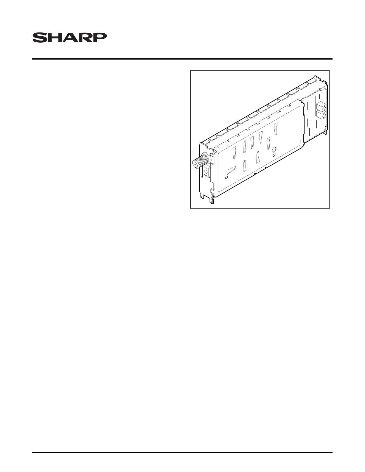
VTBT5UF201
COMB4-1
RF Data Sheet
Combination Tuner/Demodulator
FEATURES
• Receiving Standard: USA
• Receiving Channels:
–VHF Section
– Low Band – Air: 2 to 6 CATV: (A-8) A-5 to B
– High Band – Air: 7 to 13 CATV: C to W + 11
– UHF Section
– Air: 14 to 69
– CATV: W + 12 to W + 84
• Receiving System: USA Standard M-System (NTSC)
• Channel Selection System: PLL Tuning
• Detection System: Dum my Synchronization Detec-
tion System, Intercarrier Sound Receiving System
• Nominal Input Impedance: RF 75 Ω
• Output Load Impedance:
– Video: 1 kΩ
– Audio: 4.7 kΩ
• Intermediate Frequency:
– Picture: 45.75 MHz
– Sound: 41.25 MHz
• Weight: 42 g ±10 g
• Applicable Standards:
– EIA Standard Number 544
– EIA Standard Number 16A
– FCC Standards
– UL Standard
FUNCTIONAL DESCRIPTION
The VTBT5UF201 is a combination tuner and
demodulator in one package. I t is compatible with North
American NTSC television broadcast signals. An internal Phase-Locked Loop circuit performs all of the
required tuning fu nctions. The tuner and demodulator
blocks are internally connected. An IF sample port is
provided for monitoring the si gnal level or frequency
characteristics of the recovered IF signal. The RF connector is mounted on the end of the housing so that the
smallest possible area is used on the rear panel of a
final installation. Demodulated audio, video, and AFT
outputs are provided. The AFT Mu te function is available as well. The AGC control line from the demodulator
to the tuner is not accessible to the system designer.
RF Data Sheet 1
VTBT5UF201 Combination Tuner/Demodulator
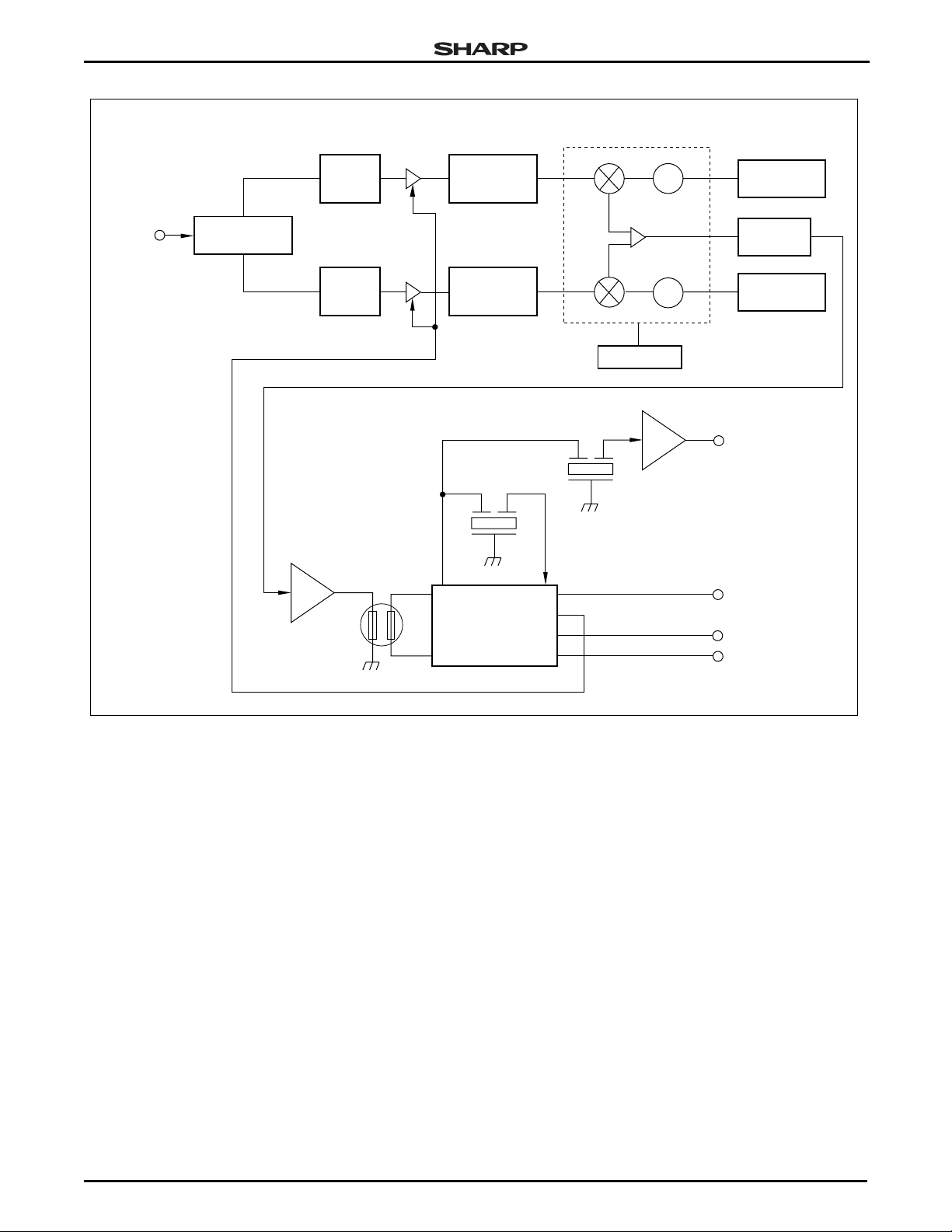
UHF/VHF
IN
U/V SEPARATE
FILTER
UHF
INPUT
TUNING
CIRCUIT
VHF
INPUT
TUNING
CIRCUIT
PRE-AMP
SAW
FILTER
RF
AMP
RF
AMP
DET
OUT
INTERSTAGE
TUNING
CIRCUIT
INTERSTAGE
TUNING
CIRCUIT
SIF
FILTER
DEMODULATOR
IC
U/V ONE CHIP AND IC
MIX
TRAP
SF IN
OSC
IF
AMP
OSC
PLL CIRCUIT
SIF
~
~
VIDEO AMP
RESONANCE
CIRCUIT
IF TUNING
CIRCUIT
RESONANCE
CIRCUIT
VIDEO OUT
AUDIO OUT
AFT OUT
AFT MUTE
Figure 1. VTBT5UF201 Block Diagram
ELECTRICAL CHARACTERISTICS
• Nominal Supply Voltage (TYP.)
– BT: 31 V
–BP: 5 V
–BM: 5 V
• Operating Voltage (TYP.)
– BT: 31 V ±2.0 V
– BP: 5 V ±0.5 V
– BM: 5 V ±0.5 V
– Control: 5 V ±0.2 V
• Breakdown Voltage (MIN.)
– BT: 34 V
–BP: 5.5 V
– BM: 5.5 V
RF AGC
COMB4-6
• Test Conditions (TYP.)
– BT: 31 V
–BP: 5 V
–BM: 5 V
– Ambient Temperature 25°C ±5°C
– Relative Humidity 65% ±10%
• Current Consumption (MAX.)
–BT: 5 mA
– BP: 16 mA
– BM: 150 mA
• Temperature (TYP. )
– Storage -20°C to +70°C
– Operating -10°C to +60°C
2 RF Data Sheet
 Loading...