

Page 1
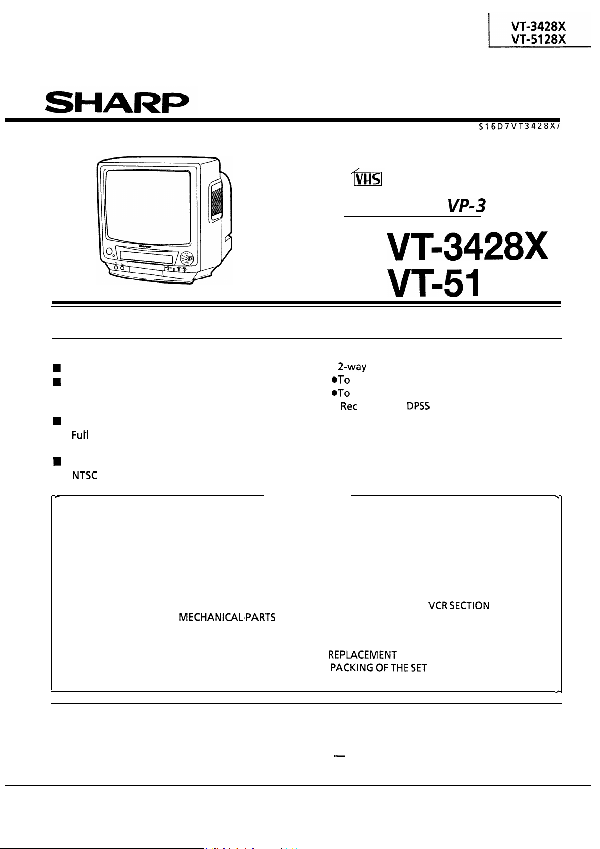
SERVICE
MANUAL
TV/VCR COMBINATION
VIDEO TV
Chassis No.
MODELS
In the interests of user-safety (Required by safety regulations in some countries) the set should be
restored to its original condition and only parts identical to those specified should be used.
FEATURES
TV/VCR Integration for Easy Operation
Single Built-in Tuner for Simple Operation
n
Timer Programme Setting by the On-Screen
Display
Auto Tracking Control
n
n
n
Auto Head Cleaning System
On-screen Display with Menu Screen Guidance
Wake-Up/Sleep Timer
Simple Playback
n
Lock Operation Mode
Lock the Power Off.
n
System)
n
Full Auto Play Function
n
Auto Repeat Playback
n
Front input terminals Audio/Video
CONTENTS
l
SPECIFICATIONS
l
IMPORTANT SERVICE NOTES
. LOCATION OF USER’S CONTROL
. DISASSEMBLY AND REASSEMBLY
. ADJUSTMENT OF THE TV ELECTRICAL
CIRCUITRY
. PRECAUTIONS IN REASSEMBLING
. FUNCTION OF MAJOR
. ADJUSTMENT, REPLACEMENTAND
ASSEMBLY OF MECHANICAL PARTS
ADJUSTMENT OF THE VCR ELECTRICAL..
.
CIRCUITRY
. TROUBLESHOOTING
........................
.............
.........
.............................
............................
...................
........
.
.......
..
Page
2
3
4
6
8
15
16
18
42
45
l
OVERALL SCHEMATIC DIAGRAM
l
CHASSIS LAYOUT OF TV SECTION
.
BLOCK DIAGRAM OF TV SECTION
.
DESCRIPTION OF TV SECTION
SCHEMATIC DIAGRAM
.
CHASSIS LAYOUT OF VCR SECTION
l
BLOCK DIAGRAM OF
. DESCRIPTION OF VCR SECTION
SCHEMATIC DIAGRAM
. PRINTED WIRING BOARD ASSEMBLIES
. REPlACEMENT PARTS LIST
.
.................
.................
.................
........
.......
.......
............
......
......
...
Page
57
59
61
65
79
81
91
97
105
134
WARNING
The chassis in this receiver is partially hot. Use an isolation transformer between the line cord plug and
power receptacle, when servicing this chassis.
To prevent electric shock, do not remove cover. No user
qualified service personnel.
serviceable parts inside. Refer servicing to
SHARP CORPORATION
Page 2
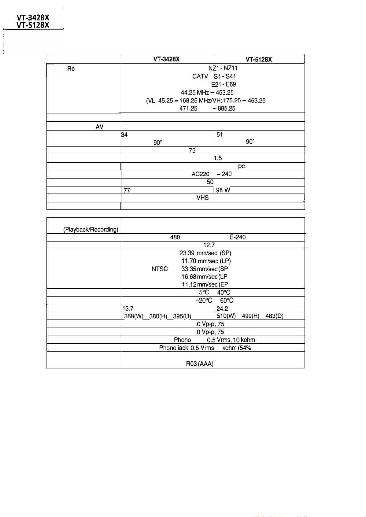
SPECIFICATIONS
I
I
I
Number of Video Heads I
Model
Reception channels
VHF band
UHF band
Receiving System
Antenna input
Audio output
Speaker
Rated voltage
Rated frequency
Power consumption
Video cassette format
Video recording system
Video signal
Screen
cm “Viewable” measured
diagonally,
I
W
deflection
Two rotary heads, helical scan
VHF :
UHF :
MHz
ohm unbalanced
8 cm round type x 1
: Sl
PAL B/G
PAL
Max.
V
Hz
standard
2
PAL
MHz
MHz
cm “Viewable” measured
diagonally, 90’ deflection
W
V
28X
MHz)
I
Recording/playing time
Tape width
Tape speed
Operating temperature
Storage temperature
Weight
Dimensions
Video input
output
Audio input
output
Supplied accessories Operation manual, wireless remote control unit,
*Design and specifications are subject to change without notice.
kg
PAL
x
minutes max. with
:
:
x
mm
1
1
jack:
to
battery x 2
mm
playback only)
playback only)
playback only)
kg
x
ohm
1
tape
MOD)
x
mm
2
Page 3
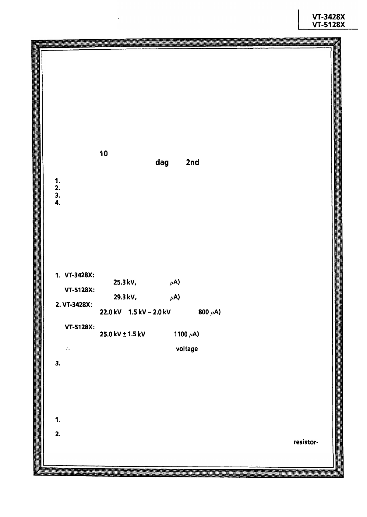
IMPORTANT SERVICE NOTES
Maintenance and repair of this receiver should be done by
qualified service personnel only.
SERVICING OF HIGH VOLTAGE SYSTEM AND
PICTURE TUBE
When servicing the high voltage system,
connecting a
probe) between picture tube
be disconnected from AC outlet.)
Picture tube in this receiver employs integral implosion protection.
Replace with tube of the same type number for continued safety.
Do not lift picture tube by the neck.
Handle the picture tube only when wearing shatterproof goggles and after discharging
the high voltage completely.
k ohm Resistor in series with an insulated wire (such as a test
and
remove static charge from it by
anode lead. (AC line cord should
X-RAY
This receiver is designed so that any X-Ray radiation is kept to an absolute
minimum. Since certain malfunctions or servicing may produce potentially
hazardous radiation with prolonged exposure at close range, the following
precautions should be observed:
than
than
m-3428X: To keep the set in a normal operation, be sure to make it function on
been factory
To keep the set in a normal operation, be sure to make it function on
factory
If there-is a possibility that the high
forget to check for such high voltage after the work.
DO not substitute a picture tube with unauthorized types and/or brands which may cause
excess X-ray radiation.
(at beam 0
(at beam 0
+
-Adjusted to the above-mentioned high voltage.
(at beam
-Adjusted to the above-mentioned high voltage.
(at beam
for the set.
for the set.
in the case of the set. The set has
in the case of the set. The set has been
fluctuates as a result of the repairs, never
BEFORE RETURNING THE RECEIVER
Before returning the receiver to the user, perform the following safety
checks.
Inspect all lead dress to make certain that leads are not pinched or that hardware is not
lodged between the chassis and other metal parts in the receiver.
Inspect all protective devices such as non-metallic control knobs, insulating fishpapers,
cabinet backs, adjustment and compartment covers or shields, isolation
capacity networks, mechanical insulators etc.
3
Page 4
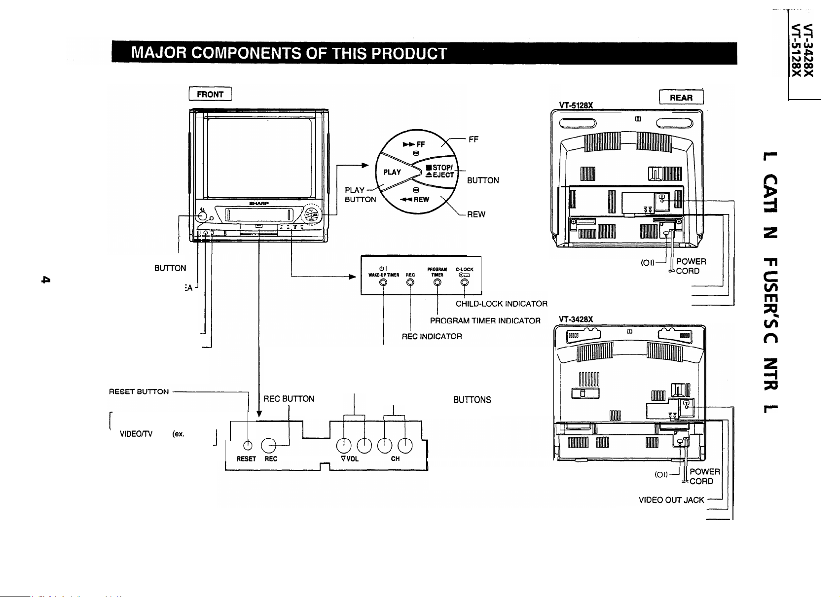
(Forward video
search) BUTTON
28X
POWER
SENSOR ARE
FOR REMOTE
CONTROL
VIDEO INPUT JACK
AUDIO INPUT JACK
NOTES:
l Use the RESET button if the
Timer, etc.) cannot be operated.
1
mode (ex.
Program
. .
: :
STOP/EJECT
(Reverse video
i
search) BUTTON
0
0
0
BUlTON
MAIN POWER SWITCH
VIDEO OUT JACK
AUDIO OUT JACK
ANTENNA IN TERMINAL
POWER/WAKE-UP
TIMER INDICATOR
VOLUME UP/DOWN BUTTONS
CHANNEL UP/DOWN BUl-t-ONS
0
0
1
l
A V
A
MAIN POWER SWITCH
AUDIO OUT JACK
ANTENNA IN TERMINAL
Page 5
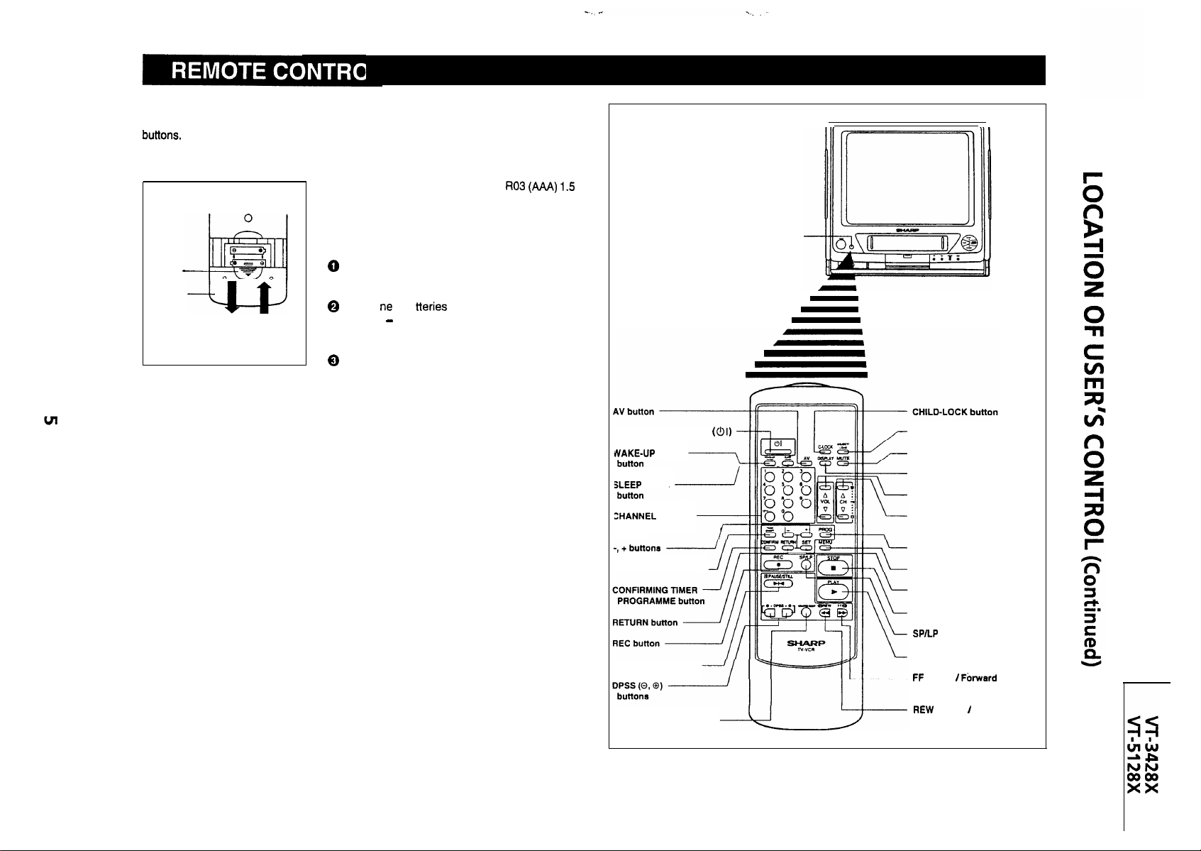
The remote control lets you operate this product at a distance. Just aim the front of the remote
control at the photoreceptor window situated on the front panel and press the appropriate
Inserting the Batteries
The remote control operates on two
volt batteries (included). If the remote control does
‘not operate or fails to function normally due to weak
batteries, new batteries can be purchased at electronics or camera stores.
Press
Down
Battery
Cover
Slide off
Slide on
Open the battery cover. (Remove any old
batteries that may be in the remote control.)
( + and
w ab
) with the markings inside the compart-
Insert
ment.
Replace the cover.
l You can set clock and timer recordings using the remote control.
SENSOR AREA
FOR REMOTE CONTROL
Clock setting:
see SETTING THE CLOCK
Timer recording: see RECORDING WITH THE TIMER
NOTES:
l Do not subject the remote control to impact, water or excessive humidity.
l
The remote control may not function if the photoreceptor window of this product is in direct
sunlight or any other strong light. If so, move the product or alter the lighting.
l Incorrect use of batteries may cause them to leak or burst.
l Do not mix old and new batteries, or mix the brands used.
l
Both rechargeable and disposable batteries are available. Read the battery warnings and
do not try to recharge disposable batteries.
l Remove the batteries if the remote control will not be used for a long time.
POWER ON/OFF button
TIMER
SELECT
buttons
TIMER ON/OFF button
PAUSE/STILL button
COUNTER RESET button
EJECT/LOAD button
MUTE button
DISPLAY button
VOLUME ADJUSTMENT buttons
CHANNEL UP/DOWN buttons
(TRACKING buttons)
PROGRAMME button
MENU button
SET button
STOP button
PLAY button
button
Video Search
Video Search
Reverse
Page 6
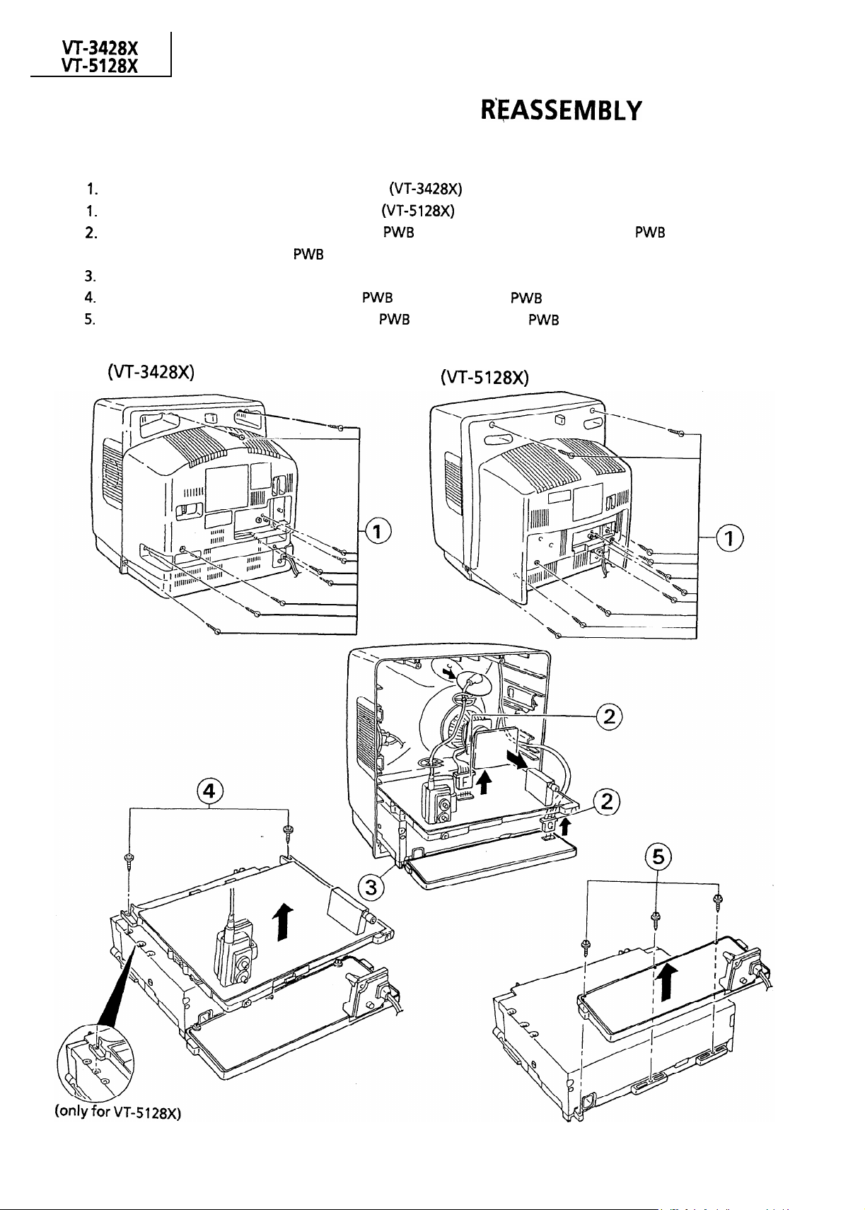
DISASSEMBLY AND
n
TV SECTION
Remove the nine screws off the rear cover.
Remove the ten screws off the rear cover. (VT-51 28X)
Disconnect the F connector from the main
the anode cap and the CRT PWB unit from the CRT.
After disconnect the coating earth from the CRT unit and take out the unit.
Remove the two screws from the main PWB and separate the
Remove the three screws from the power
and G connector from the power
from the video unit.
and separate the
from the video unit.
and disconnect
6
Page 7
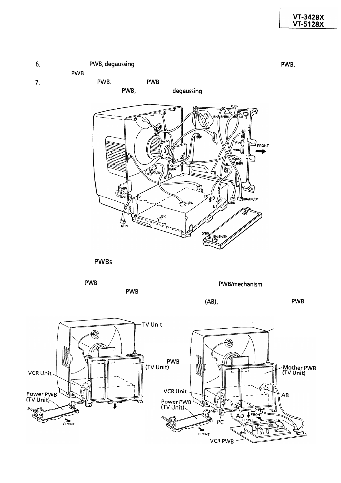
DISASSEMBLY AND REASSEMBLY
(Continued)
Remove the CRT PWB,
the main PWB upright.
Reconnect the CRT PWB. Put the main PWB and the VCR unit together as shown below. Keep the front
power switch remote control PWB, speakers and
coil connector G and front power switch remote control
coil connector G off position.
Place
n SERVICING THE
<Repairing the TV unit>
Unhook the power PWB and place it on the left
hand of the set. Set up the mother PWB as shown
below.
-Mother
FRONT
<Repairing the TV and VCR units>
Unhook the
VCR unit, and place it as shown here. Connect the
cables
start repairing.
(AD) and (PC) to the mother
assembly from the
to
TV Unit
Page 8
l PRECAUTIONS
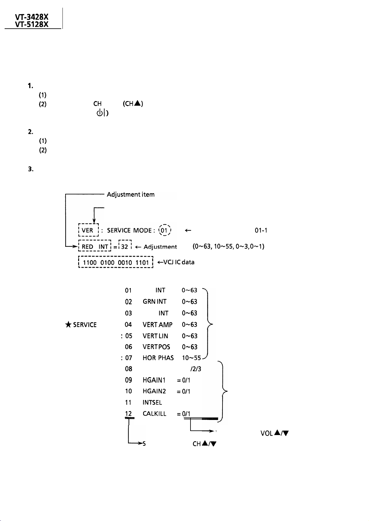
Calling the service mode
ADJUSTMENT OF THE
TV ELECTRICAL CIRCUITRY
Hold down the
POWER button ( of the set. Now the set is in the service mode.
UP key
of the set for 2 seconds or longer and at the same time press the
Clearing the service mode
There are two ways to clear the service mode. Press the MENU key on the remote control gun
Display in the service mode
ROM No. in the microprocessor
Adjustment item Nos.
L---l
data
2
*SERVICE MODE :
*SERVICE MODE :
*SERVICE MODE :
MODE :
*SERVICE MODE
*SERVICE MODE :
*SERVICE MODE
*SERVICE MODE :
*SERVICE MODE :
*SERVICE MODE :
*SERVICE MODE :
*SERVICE MODE :
RED
INT
BLUE INT
HI-VI
electable
=
=
=
= O-63
=
=
=
= O/l
= O/l
by the
General adjustment items
Basically fixed
Variable by the VOL
key
key
8
Page 9
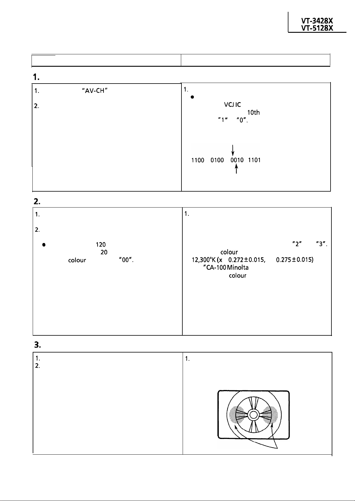
SCREEN/BACKGROUND ADJUSTMENT
.
Adjusting Conditions
Adjusting Procedures
Screen Adjustment
Receive the “AV-CH” signal. Keep the blue
background off.
Reset “video adjust” mode.
t
Call the service mode and take the step below.
Screen control:
Look at the
control so that the
turn from to
data on the screen. Adjust the
figure from left should
To be 0 here too.
To turn to 0 here.
Background Adjustment
Receive
PATTERN” signal.
In the video adjust mode, adjust the brightness
and contrast.
Bright portion:
l Dark portion:
Keep the colour adjusted at “00”.
“WHITE BALANCE ADJUSTMENT
nit
nit
Call the service mode and take the step below.
l
Red intensity :
l
Green intensity :
l
Blue intensity :
Pick up the service mode numbers
Adjust the
The
be used as a colour thermometer.
temperature as follows.
=
y =
CRT Color Analyzer” should
and
Focus Adjustment
Receive “monoscope pattern” signal.
Reset the video adjust mode to have the Video
Normal Position.
Adjust the focus control to have the best focus in
the areas between the pattern’s center. and its
both ends.
Adjust point
9
Page 10
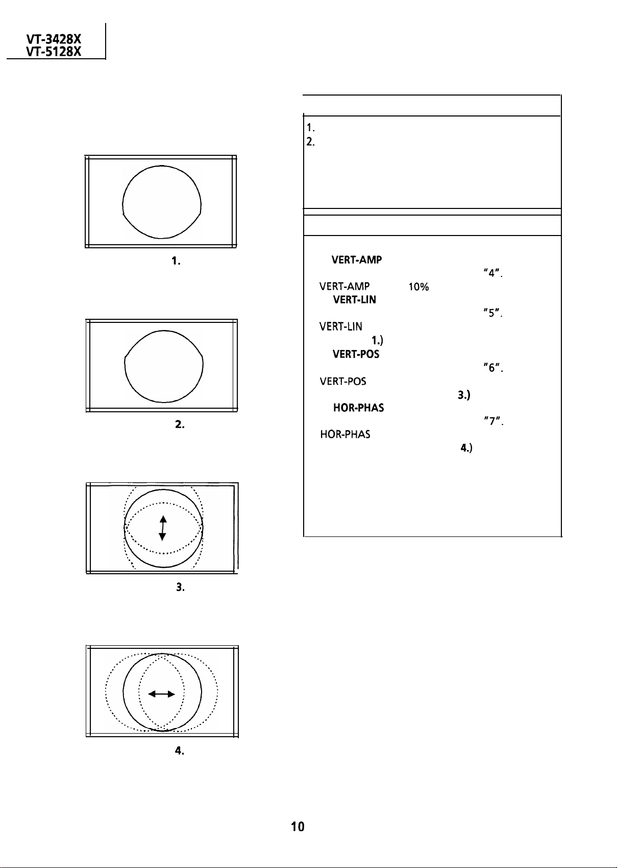
HORIZONTAL/VERTICAL CIRCUIT ADJUSTMENT
Figure
Figure
I
Receive “PAL monoscope pattern” signal.
Reset the video adjust mode to have the Video
Normal position.
I. Call the service mode and take the steps below.
l
Select the service mode number
l
Select the service mode number
Adjusting Conditions
Adjusting Procedures
(vertical size):
Adjust the
to have 10% overscan.
(vertical linearity):
Adjust the
to have optimum vertical linearity. (See
Figs. 1 and
l
Select the service mode number “6”. Adjust the
center of the screen. (See
l
Select the service mode number
(vertical center):
so that the vertical center be at the
Fig.
(horizontal center):
Adjust the
.
.
.
.
.
.
.
.
.
. . . . . . .
Figure
.
.
.
.
,
,
.
.
l ‘
,
center of the screen. ( See
Fig.
Figure
Page 11
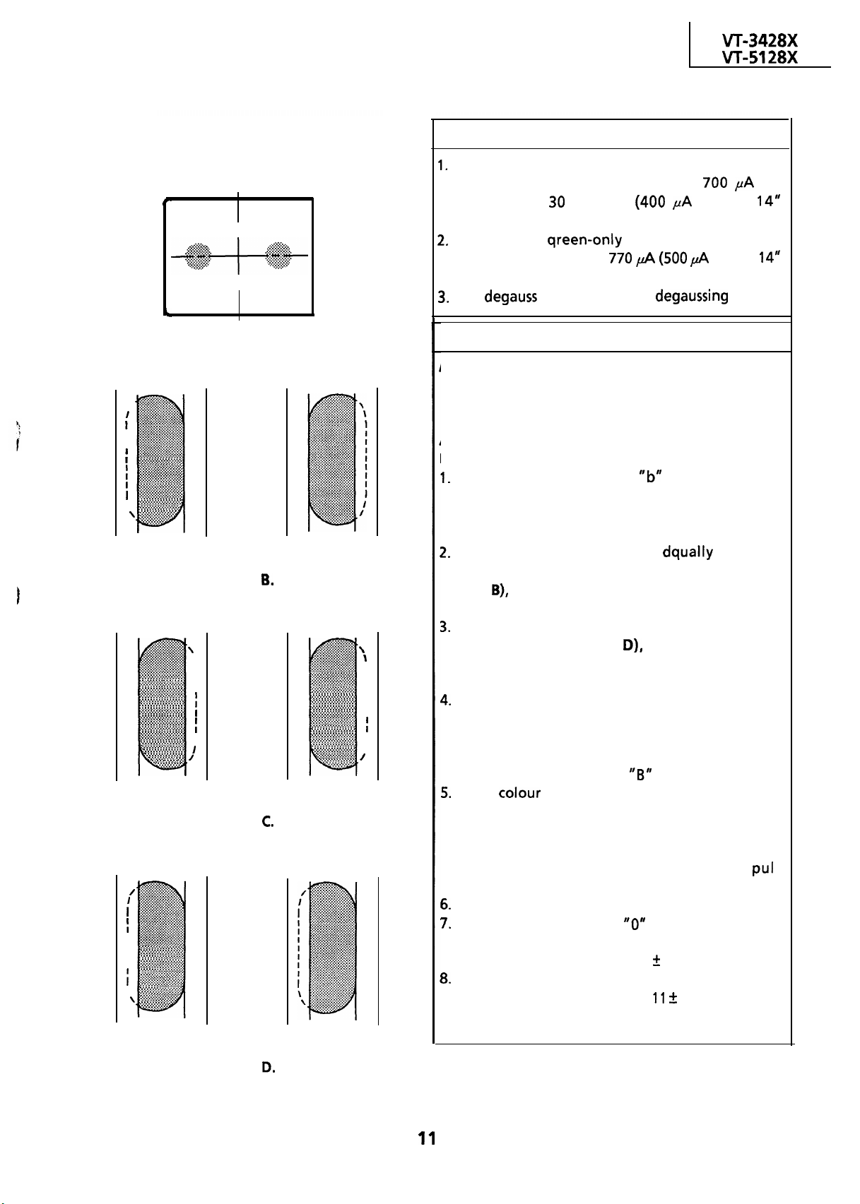
PURITY ADJUSTMENT
Adjusting Conditions
Before the purity adjustment, warm up the set
with beam current of more than 700
longer than
I
a
b
model).
Receive the qreen-only signal and adjust the
beam current to about 770
minutes (400 PA for the
(500
for the
model).
Fully
the CRT with the
for
coil.
Figure A.
Left
.
,
. . . . . . . . . . . .
. . . . . . . . . . . . . . .
I
I
. . . . . . . . . . . . . . .
\
Beam landing equally outwards.
Figure
Left
. . . .
\
I
,
,
I
I
.. . .
.
Beam landing shifted to the right.
Figure
Left
.
.
. . . . . . . . . . . . . .
. . . . . . . . . . . . . . z.
. . . . . . . . . . . . . . .
.
. . . . . . . . . . . . . . .
. . . . . . . . . . . . . . .
.
. . . . . . . . . . . . . . .
I
. . . . . . . . . . . . . . . .
. . . . . . . . . . . . . . . .
I
. . . . . . . . . . . . . . .
I
I
. . . . . . . . . . . . . . .
. . . . . . . . ...*.....
... .
. . . . .
.
. . . . . . . . . .... . . .
. . . . . . . . . . . . . . .
\
.
. . . . .
Right
Right
.
. .
1
I
I
,
I
I
I
. . . . . . . . . . . .
,
Right
Adjusting Procedures
Notes:
l
Static convergence should be roughly adjusted.
l
The purity magnet should be positioned where
the magnetic field is zero.
Adjustment:
During the adjustment, keep the set facing the east.
Observe the spots “a” and
with a microscope. Adjust the purity magnet to
have these spots at the specified landing
positions.
If the right and left spots are
outwards from their landing positions (shown in
Fig.
push the deflection yoke forwards for
proper positioning.
If both the spots are shifted to the right or left
(shown in Figs. C and
angle of the purity magnet for proper
positioning.
Make sure that the center spot
and left spots are in their specified landing
positions. Check the four corners of the CRT
screen.
See if all the landing positions are
satisfactory with the Rank “B” specifications.
If any
other than green appears, pull the
deflection coil backwards.
Landing too outwards: Deflection yoke to push
forwards.
Landing too inwards : Deflection coil to
backwards.
Receive the monoscope pattern signal.
Set the raster rotation at
facing the east.
Adjustment error: 0
Tighten up the deflection coil screws.
Tightening torque:
(shown in Fig. A)
deviated
adjust the opening
as
well as the right
position with the set
2 mm
2 kg
I
Beam landing shifted to the left.
Figure
Page 12
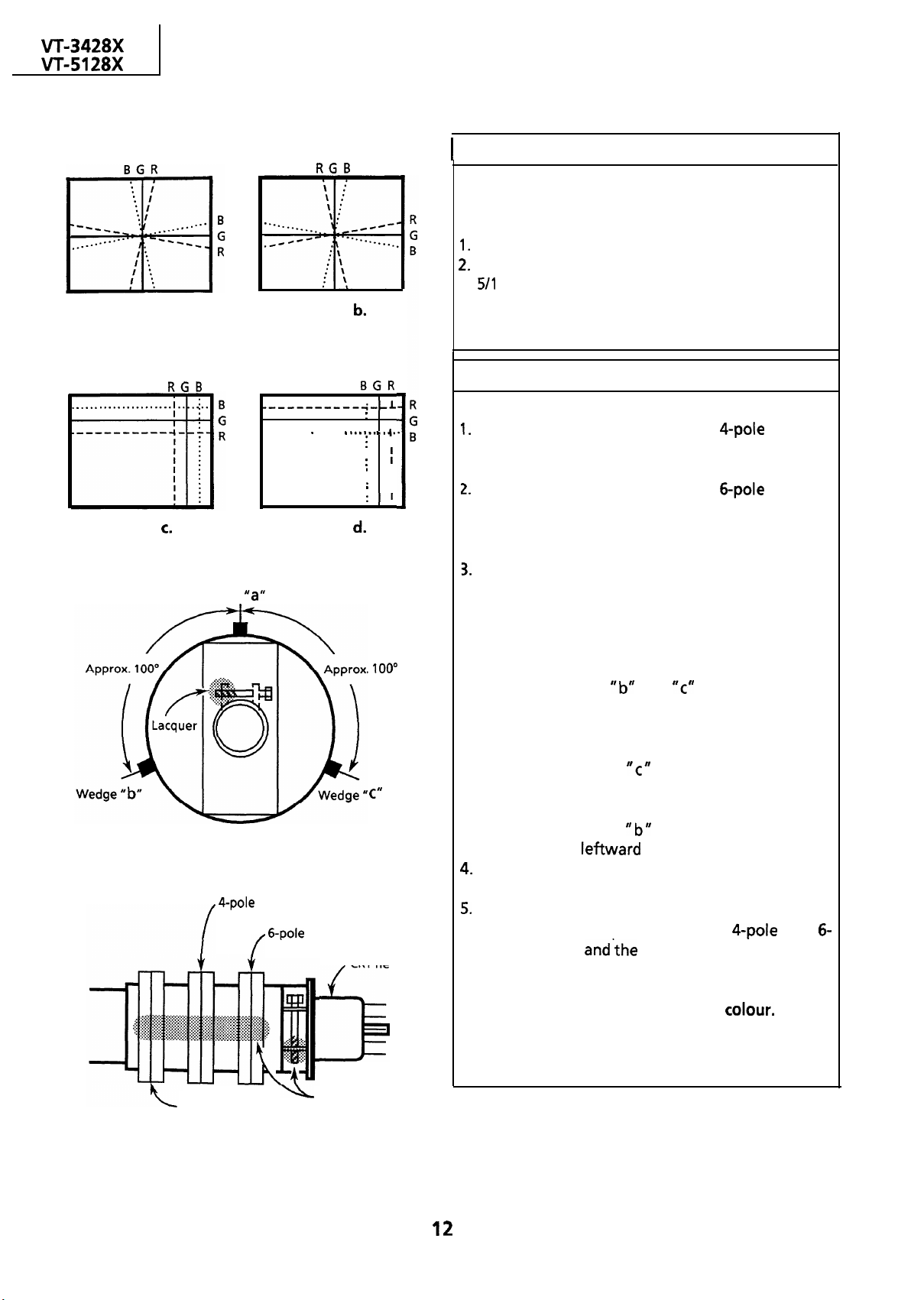
CONVERGENCE ADJUSTMENT
Adjusting Conditions
This adjustment should be performed after
the purity magnet adjustment.
Receive the crosshatch pattern signal.
Set the brightness and contrast controls to the
0 and 1 O/l 0 positions, respectively.
Figure a.
Figure
Wedge
..I..........
magnet
Figure
. . . .
Figure
magnet
I
.
I
.
.
I
.
.
I
.
CRT neck
Adjusting Procedures
STATIC CONVERGENCE
I
.
Adjust the opening angle of the
magnet
and rotate the magnet to impose the blue line
I
over the red one.
Adjust the opening angle of the
magnet
and rotate the magnet to impose the green line
over the blue one.
DYNAMIC CONVERGENCE
Take the following steps for dynamic
convergence at the edges of the CRT screen.
l
Convergence in Fig a :
Insert the wedge “a”
deflection coil upward for correct convergence.
l
Convergence in Fig b :
Insert the wedges
he deflection coil downward for correct
convergence.
l
Convergence in Fig c :
Insert the wedge
deflection coil rightward for correct convergence.
l
Convergence in Fig d :
insert the wedge
deflection coil
Stick the above wedges on the CRT, and apply
glass tape over them.
Apply lacquer to the deflection yoke screw, the
magnet unit (consisting of purity,
pole magnets)
Finally receive the red-only signal to make sure
there is no mixture with any other
same with the blue-only signal.
in position, and tilt the
and
in position, and tilt
deeper, and tilt the
deeper, and tilt the
for correct convergence.
and
magnet unit screw.
Do the
Purity magnet
Lacquer
Page 13
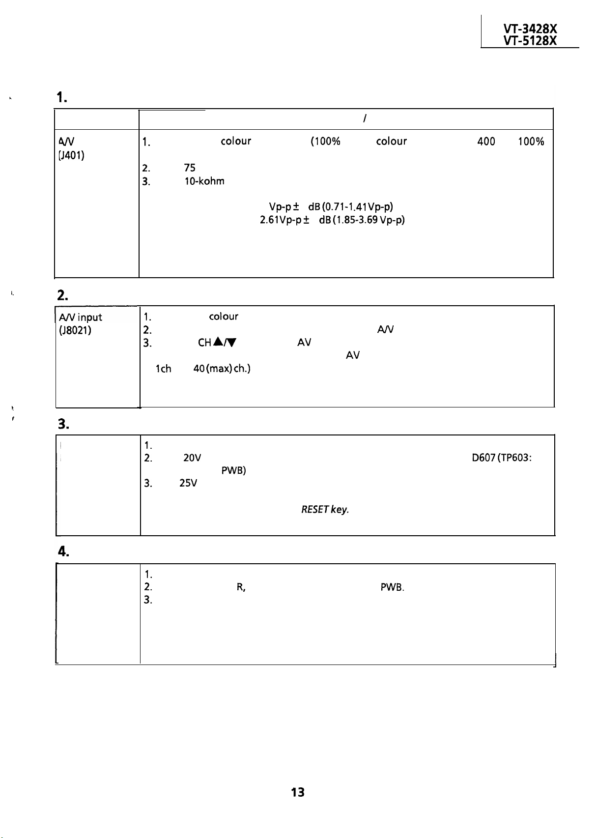
A/V Output Checking
PERFORMANCE CHECK
Adjusting Point
output
Adjusting Conditions
Receive the
modulation).
Add a
Add a
The output levels are as follows.
Note:
Make sure the video and audio outputs are as specified.
ohm terminal resistor to the video output terminal.
Video output:
Audio output:
bar signal
terminal resistor to the audio output terminal.
1
3
3
Procedures
white
bar, audio : 400 Hz, 100%
A/V Input Checking
I
Receive the
Feed the external video and audio signals via the
Using the
signals are being properly received. (The AV mode is available somewhere between
bar signal.
front jacks.
key, call the AV mode and make sure the external video and audio
Protector Performance Checking
Protector
Performance
Receive the monoscope pattern signal.
Apply
symbol on the
Feed 25V in the same way and make sure the protector is activated.
Note:
To reset the protector, press the
from the constant-voltage power supply to the cathode of
and make sure the protector is not activated.
Beam Protector Performance Checking
Beam
Protector
Performance
Receive the monoscope pattern signal.
Ground any of the
Make sure the protector is activated immediately.
Note:
To reset the beam protector, press the RESET key.
G and B cathodes on the CRT PWB.
no
Page 14
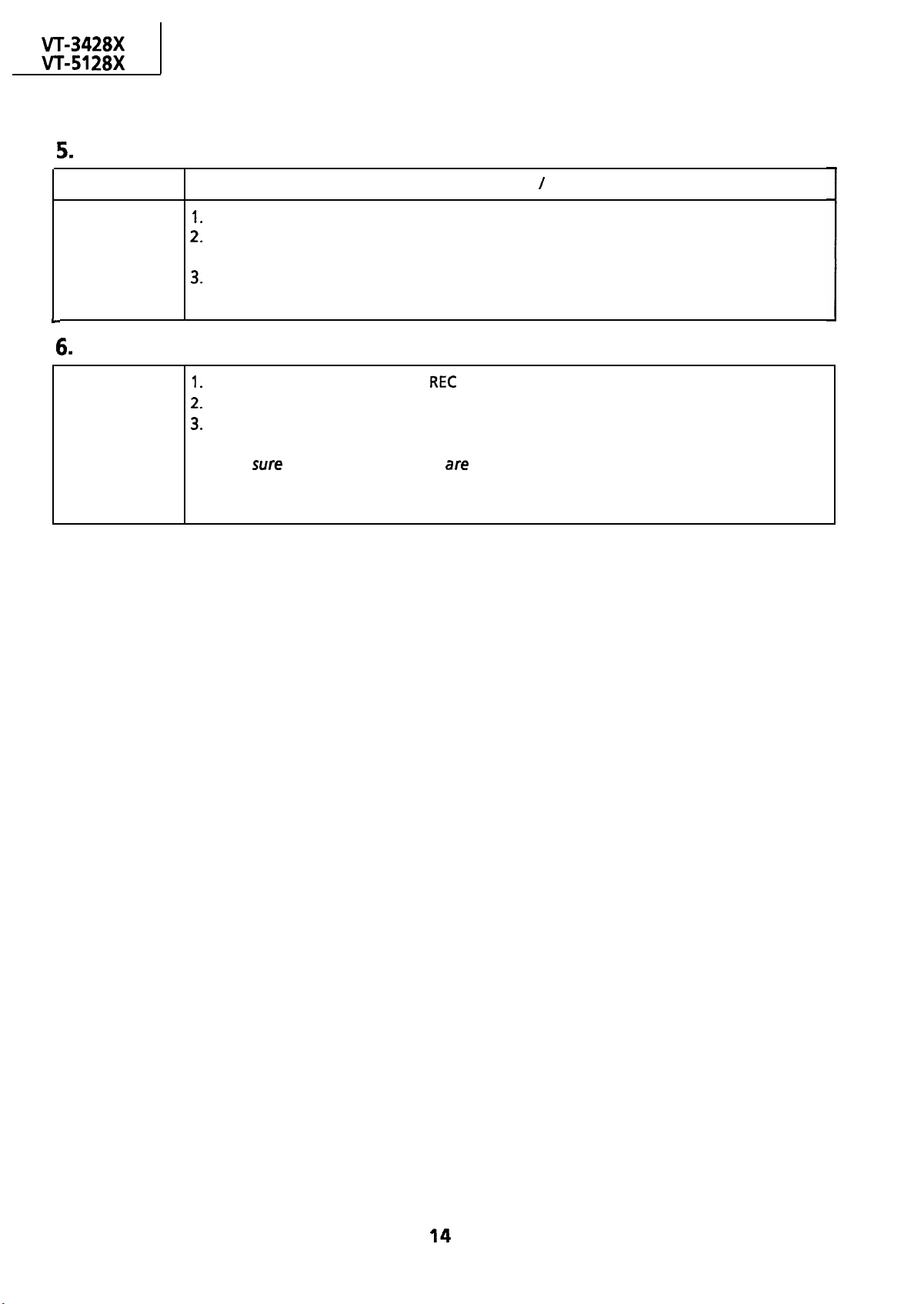
PERFORMANCE CHECK
Blue Background Checking
Adjusting Point
Blue
background
Record Index Checking
Record
index
In the SET UP mode, select the BLUE SCREEN function.
Turn on the function. With any signal input,
Make sure also that the audio is mute.
Turn off the function and make sure the blue background disappears.
In the SET UP mode, select the
Turn on the function to make recording. (Make sure the clock has been preset.)
Check the recorded contents.
Note:
Make
the channel and time
Adjusting Conditions
INDEX function.
recoded.
(Continued)
Procedures
make sure the background is blue.
Page 15
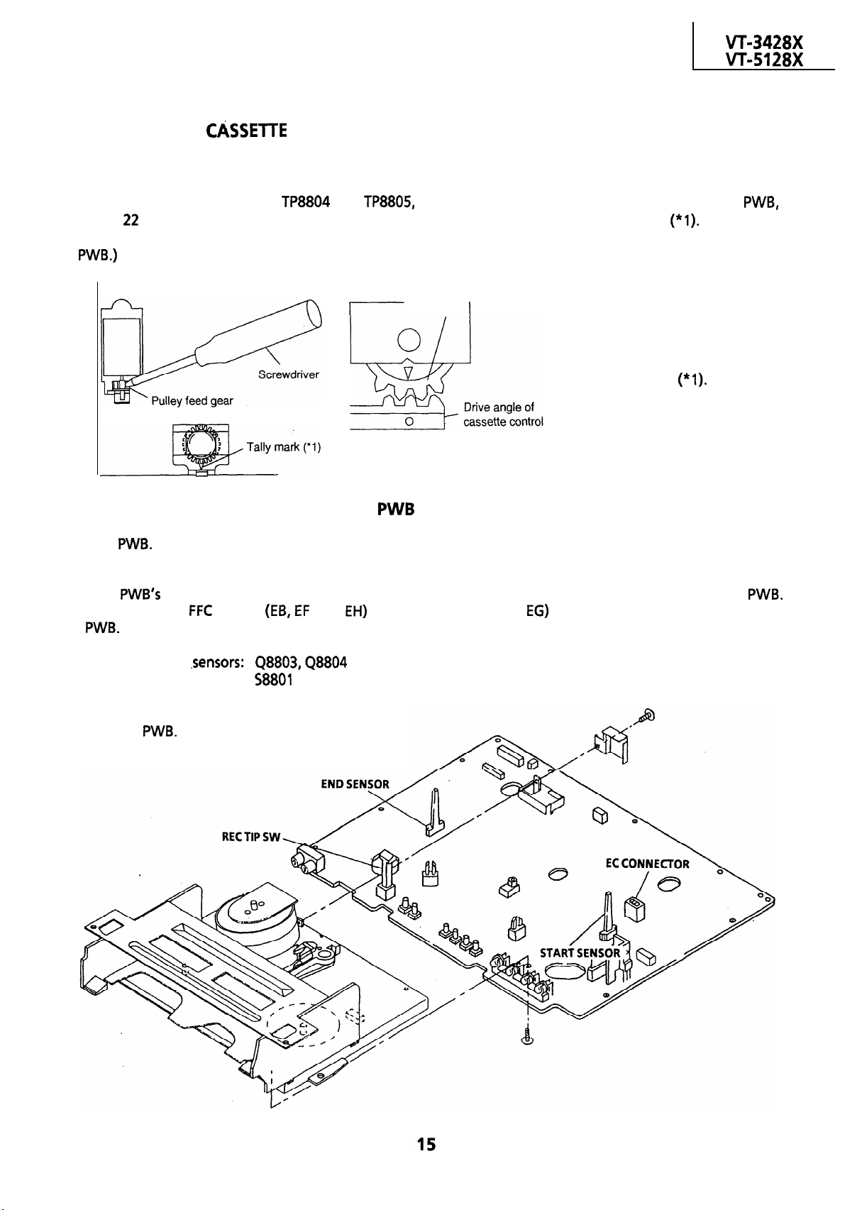
PRECAUTIONS IN REASSEMBLING
MOUNTING THE
Initial setting is indispensable
made in two ways; electrical and mechanical.
CONTROLLER
before placing the cassette controller in the mechanism. The initial setting is
Electrical setting:
Make a short-circuit between TP8804 and TP8805, both located at the center on your side on VCR
with a
the cassette controller in position. (This method is used when the mechanism has been already set on its
ohm resistor and be sure that the mechanism is back to its initial setting position
Now place
Mechanical setting:
Cassette control
drive gear
Phase matching point
Turn the loading motor’s
pulley feed gear using a
screwdriver and be sure
that the mechanism is
back to its initial setting
position
the cassette controller in
position. (This method is
applicable for the
mechanism alone.)
Now place
COUPLING THE MECHANISM TO THE
Match the mechanism’s projections with the two symbols (round reference and oval sub-reference) on the
VCR PWB. Place the mechanism straight down in position with due care so that the mechanism chassis’s
outer edges should not damage any parts nearby.
Tighten up the two screws (one for fixing the mechanism and the head amplifier shield, the other on the
VCR
Reconnect the
soldering side and located near the loading motor) to fix the mechanism and VCR PWB.
cables
and EH) and harnesses (ED and
between the mechanism and VCR
Parts to pay attention to:
Start and end
Record tip switch:
Take special care of the MC-EC connector
(board
and VCR
to
board) between
the mechanism
Page 16
I
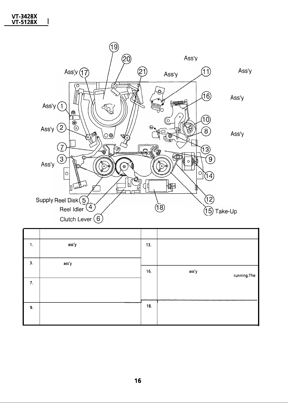
FUNCTION OF MAJOR MECHANICAL PARTS
Drum Motor
Auto Head Cleaner
Take-Up Pole
Drum
Full Erase
Head
Supply Pole
Base
Main Supply
Brake Lever
Tension
Arm
Base Ass’y
(TOPVIEW)
A/C Head
Pinch Roller
Lever
Pinch Drive Car
Pinch Drive
Lever
Reverse Guide
Main Take-Up
Brake Lever
Cassette
Housing
Drive Gear
n
No.
Full erase head
Erase the whole records on the tape in the recording
mode.
Tension arm
Detects the tension of tape while running, and brakes
the supply reel disk via the tension band.
Main supply brake lever
Brakes the supply reel disk to prevent tape slackening
when the unit is stopped in fast forward or rewind
mode.
Brakes the take-up reel disk to prevent tape slackening
when the unit is stopped in fast forward or rewind
mode.
Function
Take-Up
Lock Lever
Loading
Motor
No.
Reverse guide
Pulls out the tape and controls the tape drive train
height with the upper and lower guides.
Pinch roller lever
Press-fits tape to the capstan during tape running-The
right protrusion switches the clutch of the cassette
housing control assembly in “tape eject”, and makes
the mechanism eject tape,
Loading motor
A motive power which drives the mechanism. It
transmits the power to the master cam and cassette
housing control assembly .
Function
Reel Disk
Page 17
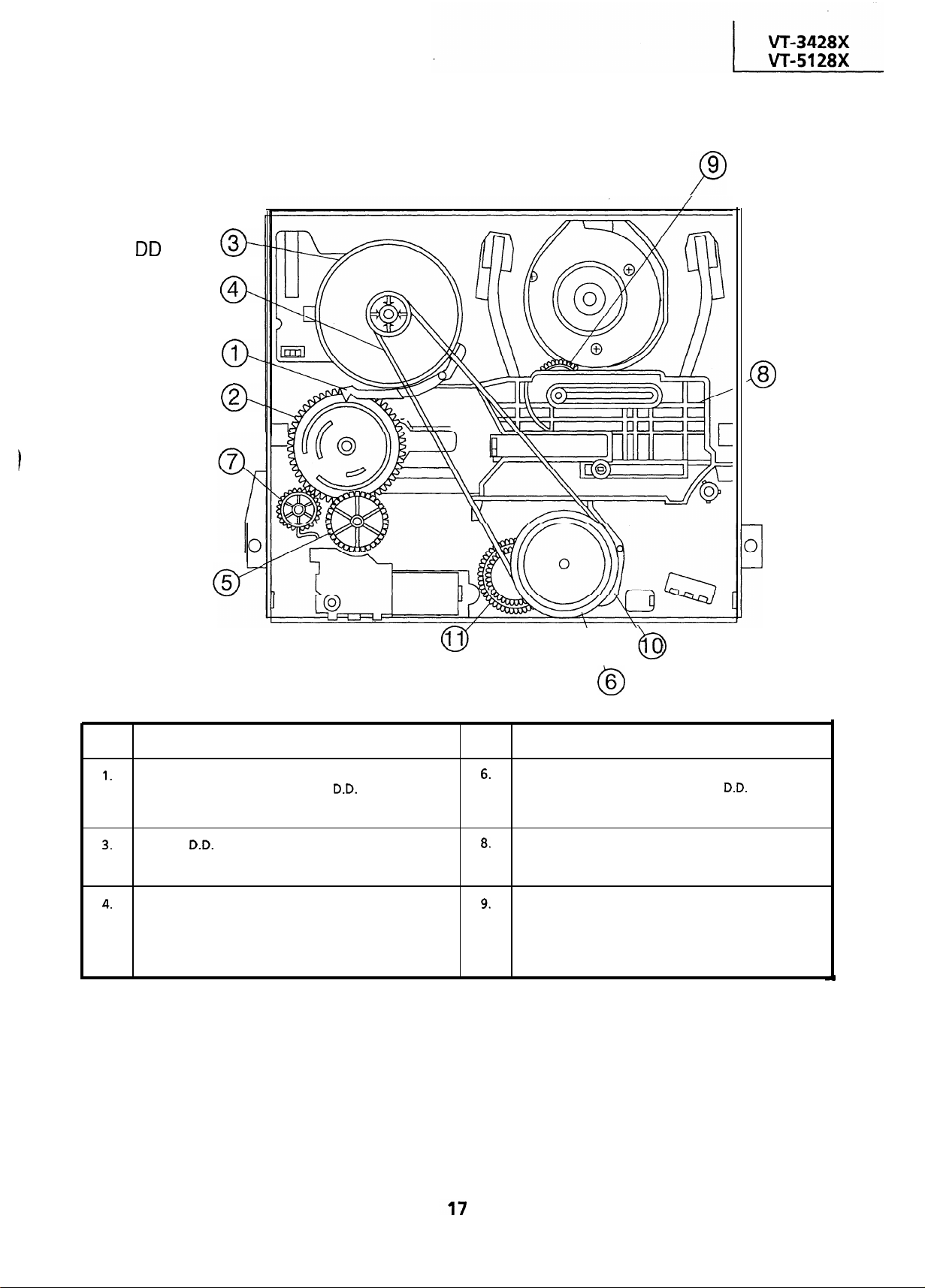
FUNCTION OF MAJOR MECHANICAL PARTS
Capstan
Motor
Reel Belt
Slow
Brake Lever
Master Cam
Cassette Housing
Drive Gear
(BOTTOM VIEW)
Take-up
Loading Gear
Shifter
Connect Gear 5
Clutch Gear
No.
Slow brake lever
Gets in contact with the capstan
the master cam in the slow still mode, and brakes it to a
certain degree.
Capstan
A motive power which runs the tape. It transmits the
power via the reel belt.
Reel belt
Transmits the power to run the tape to the reel pulley.
motor
Function
motor linking to
\
Reel Pulley
No.
Reel pulley
Transmits the power of the capstan
reel disk via the reel idler.
Shifter
Transmits the operation of the master cam to break
and loading gear.
Take-up loading gear
Shifts the take-up pole base and guide roller via the
loading relay gear, and applies the tape around the
drum assembly, as well as transmits the power to the
supply loading gear.
Clutch Connect Arm
Function
motor to the
Page 18
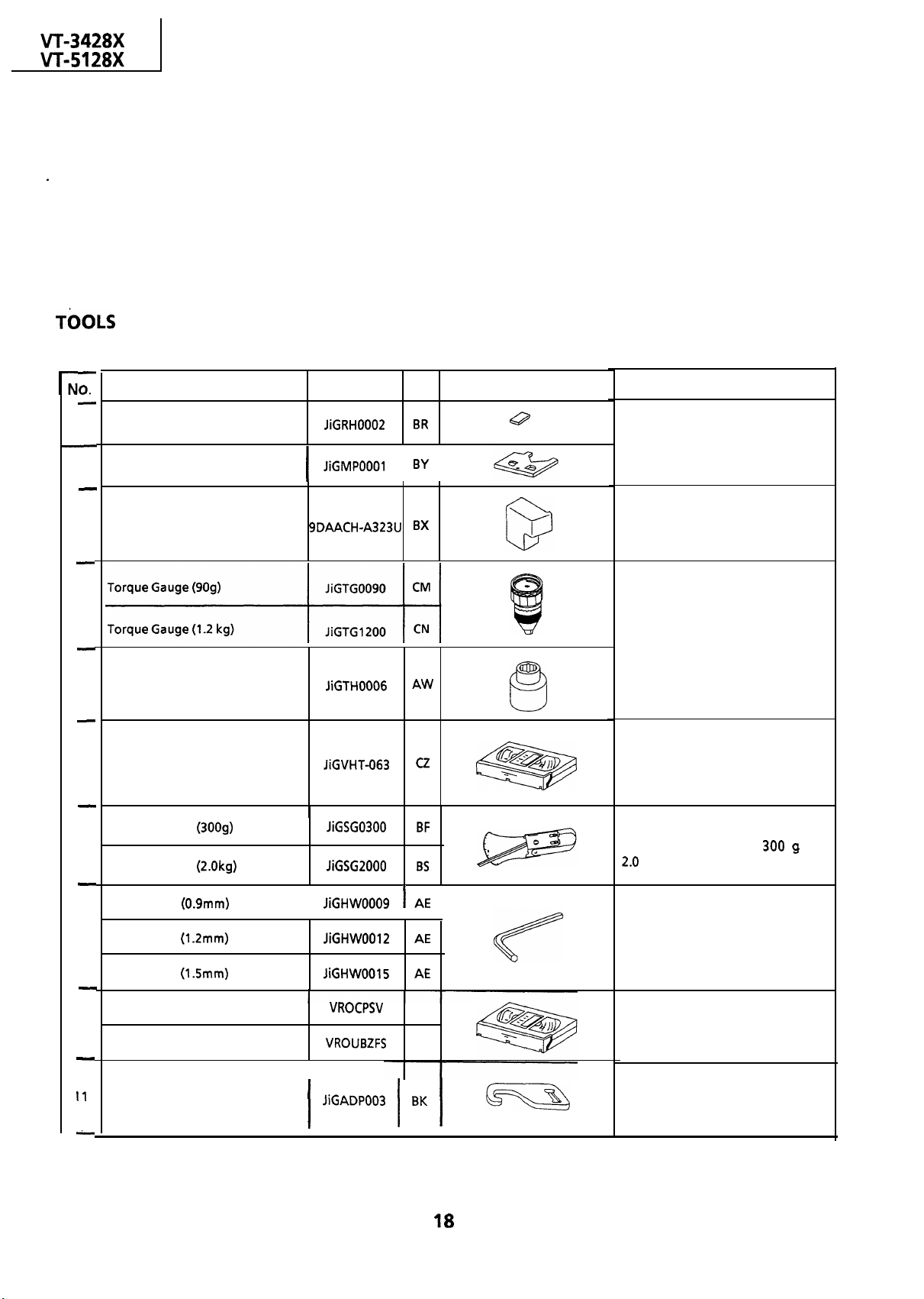
ADJUSTMENT, REPLACEMENT AND ASSEMBLY OF
MECHANICAL UNITS
Here we will describe a relatively simple service
work in the field, not referring to the more
complicated repairs which would require the use of
special equipment and tools (drum assembly
We are sure that the easy-to-handle tools listed
below would be more than handy for periodical
maintenance to keep the machine in its original
working condition.
replacement, for example).
NECESSARY FOR ADJUSTING THE MECHANICAL UNITS
The following tools are required for proper service and satisfactory repair.
Jig Item
Reel Disk Height Adjusting Jig
1
Master Plane Jig
2
3
A/C Head Tilt Adjusting Jig
4
Gauge Head
5
Part No. Code
I I
AW
Configuration
Remarks
These Jigs are used for checking and
adjusting the reel disk height.
This Jig is used for setting the A/C
head tilt.
These Jigs are used for checking and
adjusting the torque of take-up and
supply reel disks.
6
Cassette Torque Meter
Tension Gauge (3009)
7
Tension Gauge (2.0kg)
Hex Wrench (0.9mm)
a
Hex Wrench (1.2mm)
Hex Wrench (1.5mm)
Alignment Tape (PAL)
9
Alignment Tape (PAL)
Tension Gauge Adapter
This cassette torque meter is used
I
I
for checking and adjusting the
torque of take-up for measuring
tape back tension-
There
are two gauges used
tension measurements, 300
These Jigs are used for loosening or
tightening special hexagon type
screws.
These tapes are especially used for
electrical fine adjustment.
This Jig is used with the tension
gauge. Rotary transformer
clearance adjusting jig.
for the
and
Page 19
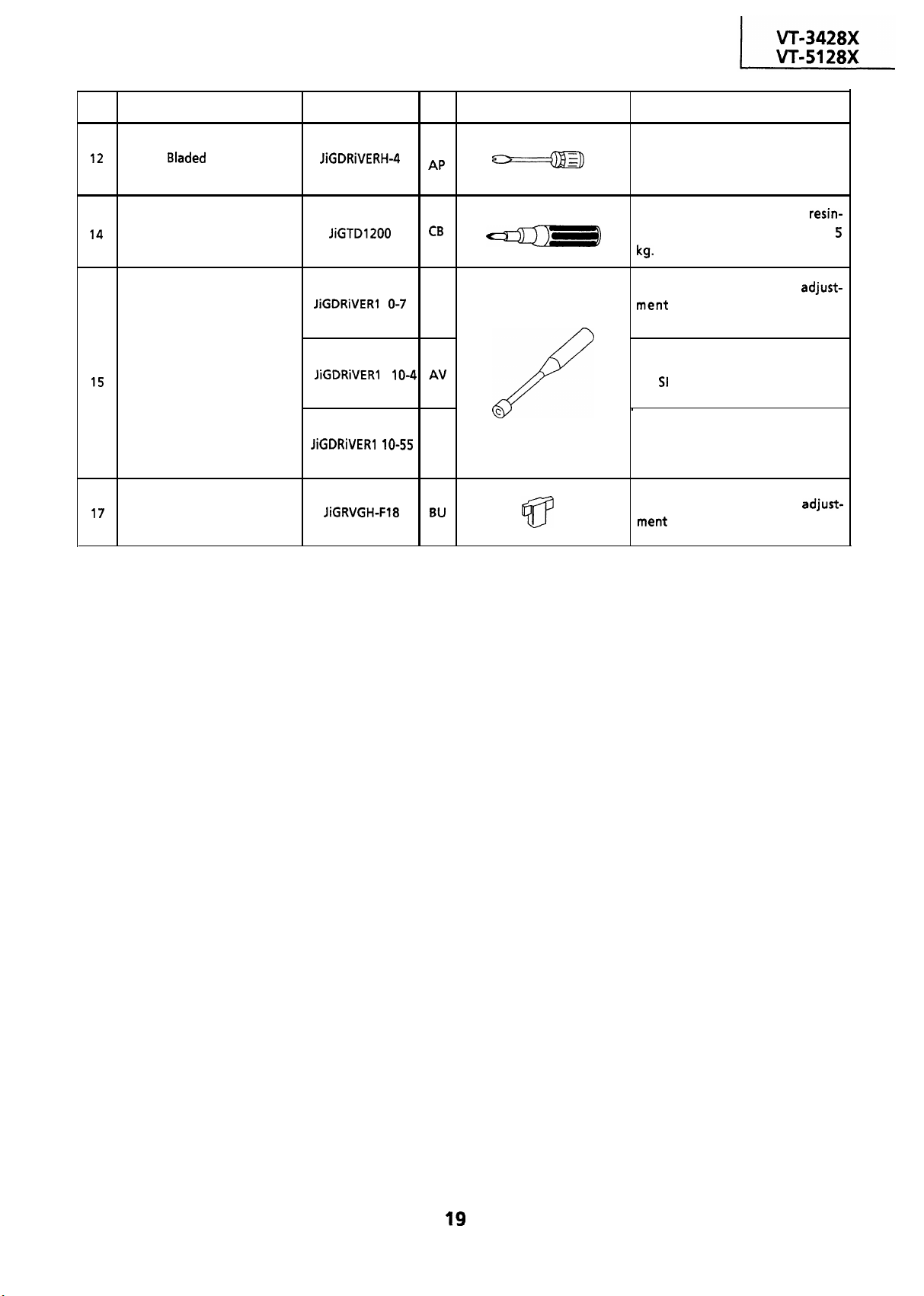
No.
Jig Item
Part No. Code
Configuration
Remarks
Special Bladed Screwdriver
Torque Driver
Box Driver
Reverse Guide Height
Adjusting Jig
AR
AS
C
:
1
This screwdriver is used for adjusting
the guide roller height.
This is used to screw down
made parts: the specified torque is
This Jig is used for height
of the A/C head and X-
position.
This Jig is used for replacement of
the
roller.
This Jig is used for height adjust-
ment of the reverse guide.
This Jig is used for height
of the reverse guide.
Page 20
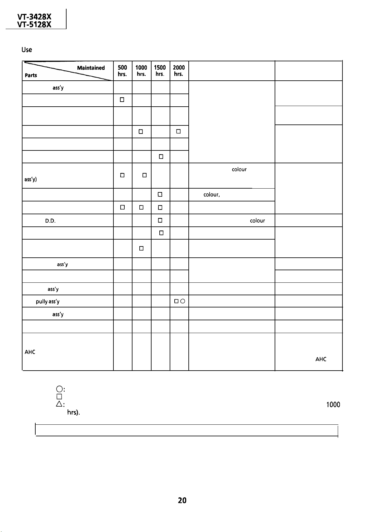
MECHANICAL PARTS REQUIRING PERIODICAL INSPECTION
the following table as a guide to maintain the mechanical parts in good operating condition.
Guide roller
Supply impedance roller
Supply impedance roller
(inner hole and shaft)
Supply impedance roller flange
Retaining guide
Slant pole
Video head (upper/Lower drum
Full-erase head
A/C head
Capstan
Pinch roller
Reel belt
Motor
q q q 0
q cl 0
cl
cl
cl cl cl El
cl q
cl
0 Cl 0 Cl
0
0
q q
cl 0
cl q
cl q
0 No tape running, tape slack
Possible symptom encountered
q
Lateral noises
Head occasionally blocked
Poor S/N ratio, no
Poor flatness of the envelope with
alignment tape
Poor
0
Sound too small or distorted
0
No tape running, uneven
No tape running, tape slack, no
0
fast forward/rewind motion
beating
Remarks
Abnormal rotation or
significant vibration
requires replacement.
Clean with pure high
quality isopropyl alcohol.
Clean tape contact part
with the specified cleaning
liquid.
Clean tape contact area
with the specified cleaning
liquid.
Clean rubber and rubber
contact area with the
specified cleaning liquid.
Tension band
Loading Motor
Reel idler
Reel
Clutch gear
Main supply/take-up brake levers
NOTE:
(Automatic Head Cleaner)
Part replacement.
:
Cleaning (For cleaning, use a lint-free cloth dampened with pure isopropyl alcohol).
q
A
0 0
0
Cassette not loaded or unloaded
0
No tape running
0
0
0 Tape slack
Oil refilling (The indicated point should be lubricated with high quality spindle oil every
If the reading is out of the specified value, clean or replace the part.
.
Replace the roller of the
cleaner when it wears
down.
Just change the
assembly for new one.
roller
,
Page 21
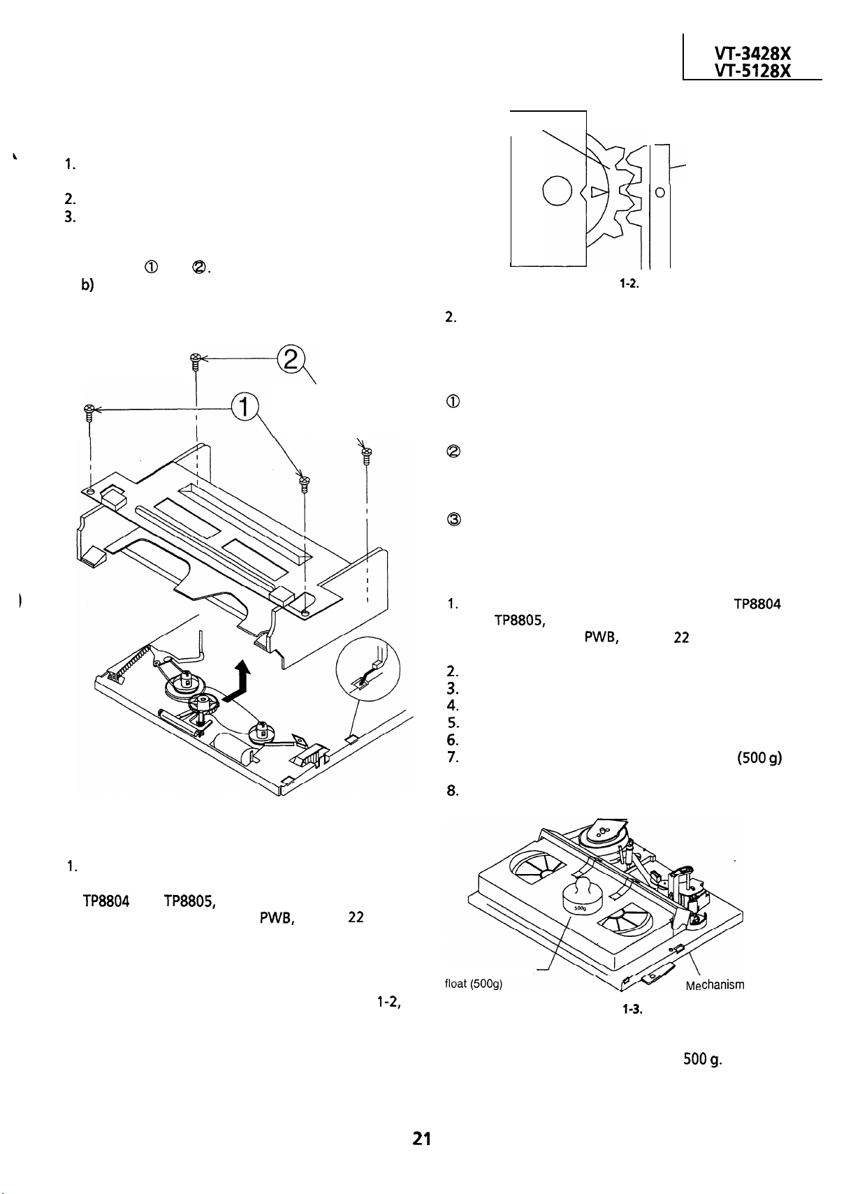
REMOVAL AND REASSEMBLY OF
CASSETTE HOUSING CONTROL ASSEMBLY
l
Removal
Set the cassette ejected condition in the cassette
eject mode.
Unplug the recorder from the main source.
Follow the procedures below in the specified
order.
a) Remove the cassette housing installation
screws
Slide and pull out the cassette housing control
assembly upward.
and
.
\
Cassette control
drive gear
Follow the procedures for removal in the reverse
order.
I
Drive angle of
cassette control
Figure
Notes:
In using a magnet screw driver, be sure to keep it
away from the A/C head, FE (Full Erase) head, or
the drum.
In removal and reassembly, take care not to hit
the cassette housing control assembly or tools
against the guide pin, drum, or the like
thereabout.
Load the cassette once onto the cassette housing
control assembly after reassembly.
Figure l-l.
l
Reassembly
Before installation of the cassette housing
control assembly, make a short-circuit between
on your side on the VCR
resistor. Plug in the power cord. The cassette
control drive gear starts and stops just when a
tally mark appears in the mechanism chassis
window. Align this tally mark with the cassette
control drive angle’s mark, as shown in Fig.
to position the cassette control on the
mechanism chassis.
with a
ohm
TO RUN A TAPE WITHOUT THE CASSETTE
HOUSING CONTROL ASSEMBLY
Be sure to make a short-circuit between TP8804
and
side on the VCR
before turning on the power.
Plug in the power cord.
Turn on the power switch.
Open the lid of a cassette tape by hand.
Hold the lid with two pieces of vinyl tape.
Set the cassette tape in the mechanism chassis.
Stabilize the cassette tape with a weight
to prevent floating.
Perform running test.
Weight to prevent
Note:
The weight should not be more than
both located at the center on your
with a
Figure
ohm resistor,
Page 22

REPLACEMENT AND HEIGHT CHECKING
AND ADJUSTMENT OF REEL DISKS
l
Removal (Supply and Take-up reel disks)
Remove the cassette housing control assembly.
Pull the tension band out of thetension arm.
Remove the supply main brake and the take-up
main brake.
Open the hook at the top of the reel disk, and
remove the reel disk.
Tension Arm Ass’y
Supply reel disk
main brake
Take-up reel disk
Notes:
@Take enough care not to deform the tension
band during installation of the supply reel disk.
Be careful not to damage the supply main brake.
l
Reassembly (Take-up reel disk)
Clean the reel disk shaft and apply oil to it.
Install a new take-up reel disk onto the shaft.
Check the reel disk height and reassemble the
take-up main brake.
Note:
Take care not to damage the take-up main brake.
After reassembly, check the video search rewind
back tension (see page
and check the brake
torque (see page 28).
Height checking and adjustment
Note :
Place the master plane onto the mechanism unit,
taking care not to hit the drum (see Figure
Figure
Note:
When the tension band is pressed in the direction
of the arrow for removal, the catch is hard to be
deformed.
Figure
l
Reassembly (Supply reel disk)
Clean the reel disk shaft and apply oil to it.
Install a new supply reel disk onto the shaft.
Replace the tension band around the supply reel
disk, and insert it to the hole of the tension arm.
4 Check the reel disk height and reassemble the
supply main brake.
Set the master plane releasing the
reverse guide by a finger.
Figure
Page 23
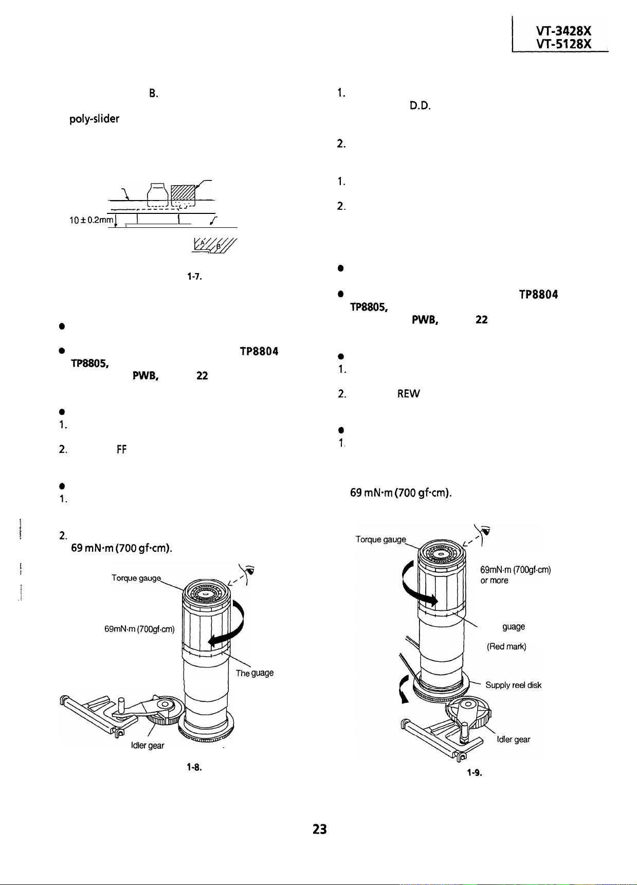
l
Check that the reel disk is lower than part A but
higher than
part
If the height is not correct,
readjust the reel disk height by changing the
Note:
Whenever replacing the reel disk, perform the
height checking and adjustment.
Master plane
.
Reel disk
Reel disk
Figure
Reel disk height
adjusting jig
Mechanism chassis
I
l
Adjustment
If the take-up torque is outside the range, clean
the capstan
motor pulley, reel belt and reel
pulley with cleaning liquid, then recheck the
torque.
If the take-up torque is still out of range, replace
the reel belt.
Notes:
Hold down the torque gauge so that it may not
fly off.
When checking the take-up torque, do not keep
the reel disk locked for a longer time.
CHECKING AND ADJUSTMENT OF TAKE-UP
TORQUE IN REWIND MODE
Remove
the
cassette housing control assembly.
CHECKING AND ADJUSTMENT OF TAKE-UP
TORQUE IN FAST FORWARD MODE
Remove the cassette housing control assembly.
Make a short-circuit between
both located at the center on your side
on the VCR
with a
ohm resistor. Now
turn on the power.
Setting
Set a torque gauge to zero on the scale. Place it
on the take-up reel disk.
Press the
button to set the mechanism to the
fast forward mode.
Checking
Turn the torque gauge slowly (one rotation
and
Make a short-circuit between
both located at the center on your side
on the VCR
with a
ohm resistor. Now
turn on the power.
Setting
Set a torque gauge to zero on the scale. Place it
on the supply. reel disk.
Press the REW button to set the mechanism to
the rewind mode.
Checking
Turn the torque gauge slowly (one rotation
every 2 to 3 seconds) by hand in the take-up
direction.
2
.
Check to see if the take-up torque is higher than
and
every 2 to 3 seconds) by hand in the take-up
direction.
Check to see if the take-up torque is higher than
I
or more
its maximum value.
(Red mark)
3
Take-up direction
Figure
is held at
Figure
The guage is held at
its maximum value.
Page 24
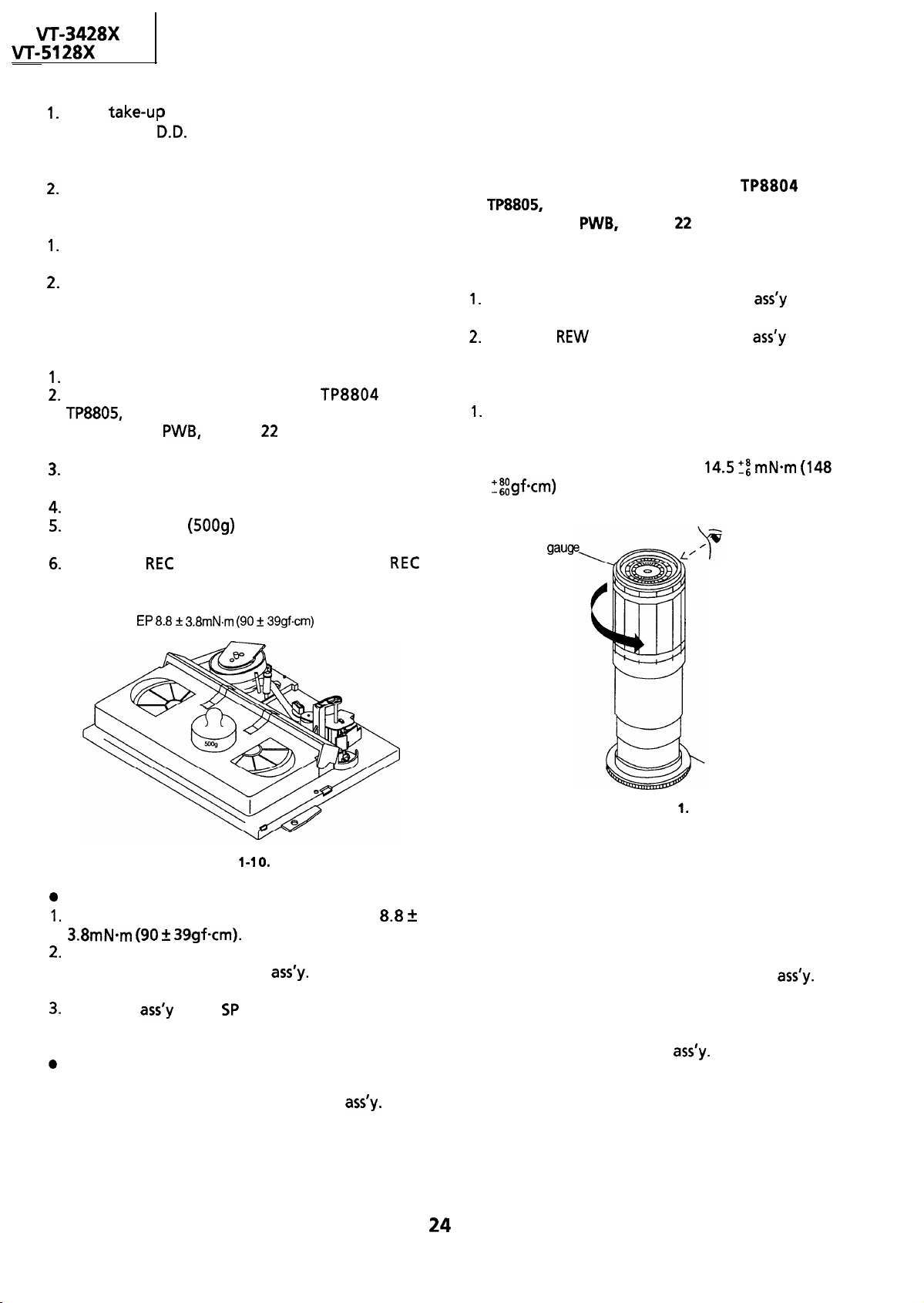
l
Adjustment
If the
the capstan
torque is outside the range, clean
motor pulley, reel belt and reel
pulley with-cleaning liquid, then recheck the
torque.
If the take-up torque is still out of range, replace
the reel belt.
Notes:
Hold down the torque gauge so that it may not
fly off.
When checking the take-up torque, do not keep
the reel disk locked for a longer time.
CHECKING AND ADJUSTMENT OF TAKE-UP
TORQUE IN PLAYBACK MODE
Remove the cassette housing control assembly.
Make a short-circuit between
on the VCR
with a
ohm resistor. Now
plug in the power cord and turn on the power.
Open the lid of the cassette torque meter, and
hold it with two pieces of vinyl tapes.
Load the cassette torque meter into the unit.
Put the weight (5009) on the cassette torque
meter.
Press the
button to put the unit in
mode.
and
CHECKING AND ADJUSTMENT OF TAKE-UP
TORQUE IN VIDEO SEARCH REVERSE
MODE
l
Remove the cassette housing control assembly.
l Make a short-circuit between
both located at the center on your side
on the VCR
with a
ohm resistor. Now
turn on the power.
l
Setting
Push the PLAY button to place the
playback mode.
Push the
video search reverse mode.
l
Checking
Place the torque gauge on the supply reel disk,
and turn it counterclockwise very slowly (one
rotation every 1 to
torque is within the set value
gfcm)
Torque
button to place the
2 seconds) and
check that the
and
in the
in the
Set value
Figure
0.
Checking
Check that the torque is in the range of 8.8
39gfcm).
The torque fluctuates due to the rotational
deviation of the reel pulley
Use the center
of the fluctuation as the value.
Place the
in the SP record mode, and check
that the take-up torque is within the range.
Adjustment
If
the take-up torque in the playback mode is
outside the range, replace the reel pulley
Note:
Stabilize the cassette torque meter to prevent
floating.
Supply reel disk
Figure l-l
Note:
Set the torque gauge securely on the supply reel
disk. If it is not secure, the measurement will be
incorrect.
l
Adjustment
If the take-up torque
in video search reverse mode
is outside the range, replace the reel pulley
Note:
The torque fluctuates due to the rotational
deviation of the reel pulley
the fluctuation at the value.
Use the center of
Page 25

CHECKING THE FAST FORWARD BACK
TENSION
l
Remove the cassette housing control assembly.
l Make a short-circuit between
both located at the center on your side
on the VCR
with a
ohm resistor. Now
turn on the power.
l
Checking
I. Push the
fast forward mode.
Place the torque gauge on the supply reel
disk, and turn it clockwise very slowly (one
rotation every 2 to 3 seconds) and check that
the torque is I
button to place the
(I 5
Torque gauge
Supply reel disk
Figure
2.
Note:
Set the torque gauge securely on the supply reel
disk. If the torque gauge is not securely set on
the reel disk, measurement will be incorrect.
and
in the
Place the torque gauge on the take-up reel
disk, and turn it counterclockwise very slowly
(one rotation every 2 to 3 seconds) and check
that the torque is I
Note:
@Set the torque gauge securely on the take-up
reel disk. If it is not secure, the measurement will
be incorrect.
weight exerted on the reel disk.
(I 3
8
CHECKING THE VIDEO SEARCH REVERSE
BACK TENSION
Remove the cassette housing control assembly.
Make a short-circuit between
both located at the center on your side
on the VCR
with a
ohm resistor. Now
turn on the power.
Checking
Push the PLAY button to place the
playback mode.
Push the rewind button to place the
video search reverse mode.
Place the torque gauge on the take-up reel disk,
and turn it counterclockwise very slowly (one
rotation every 2 to 3 seconds) and check that the
torque is within the set value 4
Torque gauge
,
,
and
in the
in the
.
weight exerted on the reel disk.
CHECKING THE REWIND BACK TENSION
l
Remove the cassette housing control assembly.
l Make a short-circuit between
both located at the center on your side
on the VCR
with a
ohm resistor. Now
turn on the power.
l
Checking
I. Push the REW
rewind mode.
Torque gauge
Take-up reel disk
to place the
l-l
,
and
in the
Take-up reel disk
Note:
Set the t
reel disk. If it is not secure, the measurement will
be incorrect.
weight not exerted on the reel disk.
gauge securely on the take-up
CHECKING THE PINCH ROLLER PRESSURE
l
Remove the cassette housing control assembly.
l Make a short-circuit between
both located at the center on your side
on the VCR
with a
ohm resistor. Now
turn on the power.
l
Checking
Push the PLAY button to place the
playback mode.
and
in the
Page 26
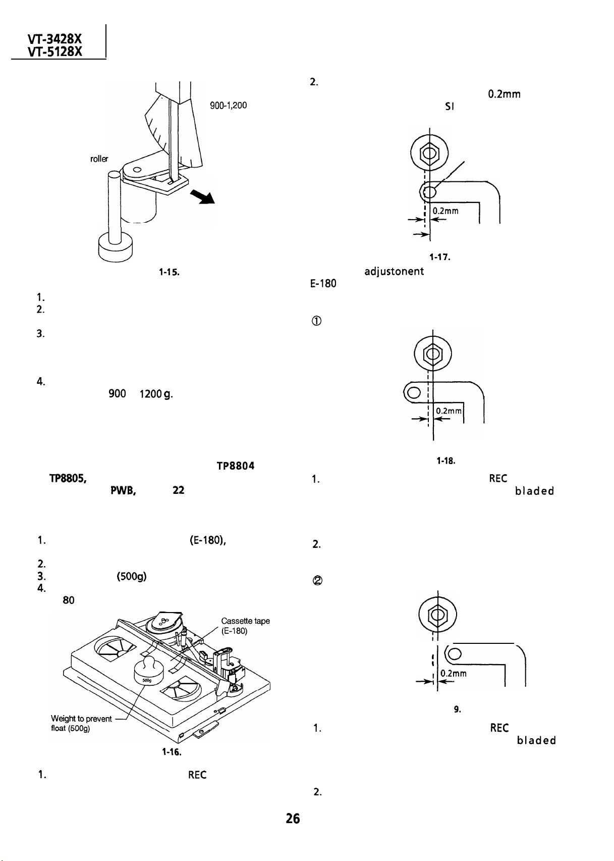
Visually check to see if the left end of the tension
Tension gauge
,200 g
pole is in alignment with the line
the center line of the SI roller. Readjust as
required in the following steps.
left of
Pinch rolle
Capstan shaft
Detach the pinch roller from the capstan shaft.
Set the tension gauge by hooking the tension
gauge adapter onto the pinch roller shaft.
Gradually release the pressure to allow the pinch
roller to touch the capstan shaft. When the
pinch roller just touches the capstan shaft, read
the indication on the gauge.
Check that the reading of the tension gauge is in
the range of 900 to
Tension gauge adapter
Figure
CHECKING AND ADJUSTMENT OF TENSION
POLE POSITION
l
Remove the cassette housing control assembly.
Tension
0.2mm
I
Center line
Figure
Make the adjustonent with the beginning of a
tape.
If the end is at the left from the center line:
pole
l Make a short-circuit between
and
both located at the center on your side
on the VCR
with a
ohm resistor. Now
turn on the power.
l
Setting
Open the lid of cassette tape (E-180), and hold it
with two pieces of vinyl tapes.
Load the cassette tape into the unit.
Put the weight
Make the adjustment with the beginning of a
E-l 80 tape.
l
Checking
Set a cassette tape, press the
the tape loaded. Now check the tension pole
position.
on the cassette tape.
Figure
button and get
Figure
Remove the cassette and press the
make an empty loading. Put a bladed
screwdriver into the tension band positioning
cam and turn it clockwise.
Place the cassette in position and check the
tension pole position.
If the end is at the right from the dotted line:
I
.
i
I
0
button to
I
I
Figure l-l
Remove the cassette and press the
make an empty loading. Put a bladed
screwdriver into the tension band positioning
cam to turn it counterclockwise.
Place the cassette in position and check the
tension pole position.
button to
Page 27
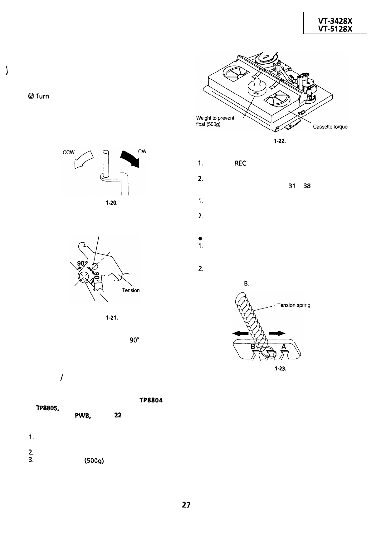
Note:
@The tension band positioning cam cannot be
adjusted with a cassette in place because the cam
will be located below the cassette. Repeat a
series of steps; empty loading, adjustment,
cassette placement and position checking.
the positioning cam clockwise to move the
tension pole to the right (in the black-arrow
direction). Turn it counterclockwise to move the
tension pole to the left (in the white-arrow
direction).
Figure
@Adjustable range of the tension pole positioning
cam.
\
Tension arm shaft
arm
meter
Figure
l
Checking
Push the
button to place the unit in the
record mode.
Check that the back tension indicated by the
gauge is within the set range
to 38 g-cm.
Notes:
Make sure that the video cassette tape is over
the retaining guide.
Make sure that the tape is not slack nor
damaged at either end.
Adjustment
If the reading of the cassette torque meter is less
than specified, move the tension spring hook
toward A.
If the reading of the cassette torque meter is
more than specified, move the tension spring
hook toward
Tension pole adjusting cam
Figure
Adjust the tension pole positioning cam so that the
arrow mark on the cam be within
left and right
from the tension arm shaft’s center.
CHECKING AND ADJUSTMENT OF
RECORD
l
Remove the cassette housing control assembly.
l Make a short-circuit between
on the VCR
turn on the power.
l
Setting
Open the lid of the cassette torque meter, and
hold it with two pieces of vinyl tapes.
Load the cassette torque meter into the unit.
Put the weight (5009) on the cassette torque
meter.
PLAYBACK BACK TENSION
and
both located at the center on your side
with a
ohm resistor. NOW
Figure
Page 28
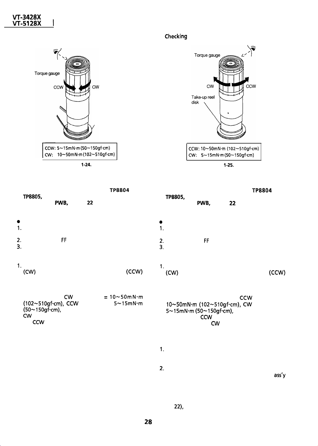
I
CHECKING THE BRAKE TORQUE
l
Checking the brake torque at the supply side
,
Supply reel disk
5mN.m (SO-1
Figure
l
Remove the cassette housing control assembly.
l
l
Remove the cassette housing control assembly.
the brake torque at the take-up
5mN.m (SO-1
Figure
side
l Make a short-circuit between
and
both located at the center on your side
on the VCR
with a
ohm resistor. Now
turn on the power.
Setting
Set a torque
on the supply reel disk.
Switch from the
Disconnect the AC power plug.
l
Checking
Slowly rotate the torque gauge in the clockwise
direction and counterclockwise
direction of the supply brake so that the reel disk
and the indicator of the torque gauge rotate at
an equal rate. Check that the values are within
the range of
direction is at least twice as high as that in
the
gauge to zero on the scale. Place it
mode to the STOP mode.
and that the brake torque in the
direction.
direction
direction =
l Make a short-circuit between
and
both located at the center on your side
on the VCR
with a
ohm resistor. Now
turn on the power.
Setting
Set a torque gauge to zero on the scale. Place it
on the take-up reel disk.
Switch from the
Disconnect the AC power plug.
l
Checking
Slowly rotate the torque gauge in the clockwise
direction and counterclockwise
direction of the take-up brake so that the reel
disk and the indicator of the torque gauge
rotate at an equal rate. Check that the values
are within the range of
torque in the
high as that in the
l
Adjustment of the brake torque at the supply
mode to the STOP mode.
direction is at least twice as
and that the brake
direction.
direction=
direction =
side and the take-up side
If the supply or take-up brake torque is outside
the range, clean the supply or take-up reel disk
break lever pad, then recheck the torque.
If the supply or take-up brake torque is still
outside the range, replace the main brake
or the main brake spring.
Note:
When the main brake is replaced, perform the
height checking and adjustment of reel disks (see
page
and the brake torque checking.
Page 29
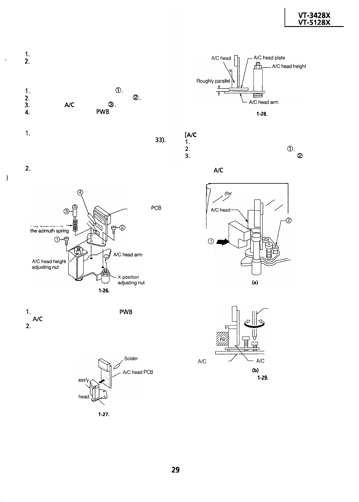
REPLACEMENT OF A/C (Audio/Control)
HEAD
Remove the cassette housing control assembly.
Place the unit in the unloading mode, and
unplug the power cord.
l
Removal
Loosen the tilt adjusting screw
Remove the azimuth adjusting screw
Remove the
Unsolder the A/C head PWB soldered to the A/C
head assembly.
Notes:
After replacement, be sure to perform the
adjustment of the tape drive train (see page
Under any circumstances, avoid touching the
head. Clean the head, if touched with your
finger, with alcohol.
Take care that the azimuth spring does not fly
off when removing the A/C head screw.
head screw
adjusting nut
Figure
l
Adjustment
head tilt angle]
Set the mechanism to the loading mode.
Place the A/C head tilt adjusting Jig
Slowly turn the tilt adjusting screw
screw driver until there is no gap between the Jig
and the
head.
A piece of white paper
visuality of a gap)
with a
A/C head
Pay attention to
Figure
l
Replacement
Solder the removed A/C head
onto a new
head assembly.
The A/C head assembly is attached so that the
A/C head arm and A/C head plate are roughly
parallel to each other.
A/C head
New
A/C head tilt
adjusting jig
head arm
Tilt adjusting
screw
Screw driver
head
Figure
Never
touch the
A/C head plate
Figure
Page 30
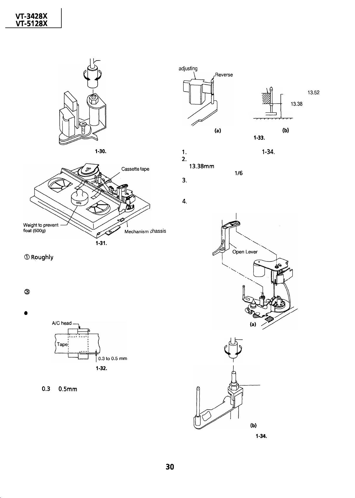
[A/C head height rough adjustment]
l
Setting
Box driver
Figure
HEIGHT ADJUSTMENT OF REVERSE GUIDE
[Height adjustment of reverse guide]
Reverse guide height
guide
Reverse guide height
adjusting jig
Go-end is
mm. Not go-end
is
mm
Figure
Remove open lever (Figure
In the tape load mode, make adjustment at the
side first and then rotate the height
adjusting nut by
turn counterclockwise.
Actually load the unit with a tape, put it in the
play mode, and make sure the tape is free from
wrinkles near the reverse guide.
Use a commercially available box driver to turn
the height adjusting nut.
(a))
Figure
adjust the height of the A/C head by
turning the A/C head adjusting hexagon nut
with the specialized box driver until the tape is in
the position shown below.
@Set the cassette tape to the mechanism chassis.
playback
mode.
Adjustment
Figure
Adjust the nut visually so that the control head is
visible
to
below the bottom of the tape.
Box driver
Height adjusting nut
Figure
Page 31

ADJUSTMENT OF TAPE DRIVE TRAIN
Remove the cassette housing control assembly.
Make a short-circuit between
and
on the VCR
with a
ohm resister. Now
turn on the power.
Check and adjust the position of the tension
pole. (See page 26.)
Check and adjust the video search rewind back
tension. (See page
Set the tilt angle of the A/C head. (See page
Rough adjustment of tape drive train.
a) Connect the oscilloscope to the test point for
envelope output (TP2203). Set
the synchronism of the oscilloscope to EXT.
The
signal is to be triggered by
the head switching pulse
Loosen the setscrew at the lower part of the
guide roller, and adjust it with an adjusting
screw driver
so that the guide
roller turns smoothly. (Do not overloosen the
setscrew, which causes insecurity of the guide
roller.) (See Figure
Set the alignment tape (monoscope pattern)
on the reel disk, and place the unit in the
playback mode.
(Place a
g weight on the cassette tape to
prevent floating of the cassette tape.)
Guide roller
Wrinkles at upper flange
Wrinkles at lower flange Counterclockwise
Figure
Clockwise
Notes:
Place the tracking control in the center position,
and adjust the X-position adjusting nut so that
the
envelop becomes maximum for
easier rough adjustment of the tape drive train.
In the rough adjustment, pay particular
attention to the outlet side.
Figure
Figure
In the X value adjustment mode (see the
Electrical Adjustment), change the envelope
waveform from MAX to
by pushing the ( + ) or
and
to MAX
tracking button, and
check a flat response is obtained on the
waveform.
If a flat response cannot be obtained, roughly
adjust the guide rollers on the supply side and
take-up side using an adjusting screw driver
until a flat response can be obtained.
Turn the A/C head tilt adjusting screw with a
screwdriver to prevent the tape from
wrinkling at the upper and lower flanges of
the fixed guide.
Wrinkles at the upper flange : Turn the
above adjusting screw clockwise, as shown
in Figure
Wrinkles at the lower flange
(a).
Turn the
above adjusting screw counterclockwise, as
shown in Figure
Loosen the setscrew
Figure
X-position
adjusting nut
Figure
Page 32

Head switching pulse
envelope
Figure
Adjustment of A/C head height and azimuth
Connect an oscilloscope to the audio output
terminal.
Use the alignment tape and play back its
audio 6
signal (monoscope pattern for
video signal). Adjust the azimuth adjusting
screw to obtain the maximum audio output
on an oscilloscope. (See Figure
Use the alignment tape and play back its
audio 1
signal (colour bar for video signal)
and slowly rotate the A/C head height
adjusting nut with the special box driver to
obtain the maximum audio output.
Perform the adjustment in
After this adjustment, apply
again.
to the
screws and nuts to fix them.
Box driver
Azimuth adjusting
screw
Figure
.
Adjustment of tape (VROUBZFS) drive train and
8
A/C head height
adjusting screw
nut
Figure
X-Position.
Connect the oscilloscope to the test points
for
envelope output.
Set the synchronism of the oscilloscope to EXT.
The
signal is to be triggered by
the head switching pulse
Play back the tape drive train alignment tape.
Push the
or
button to change the
envelope waveform from MAX to MIN, and
to MAX. Adjust the guide roller’s height
on the supply and take-up sides with an
adjusting screw driver, to obtain an envelop
waveform that is as flat as possible.
If the tape is above or below the helical lead,
the
waveform will take the shape
shown in Figure
Adjust for maximum flatness of the envelope
as the step 6,
in page 31.
.
Adjustment
When the tape is above the helical lead. When the tape is below the helical lead.
Supply side
Take-up side
Supply side
Take-up side
Supply side guide
roller rotated in
clockwise direction
(lowers guide roller) to
flatten envelope.
Take-up side guide
roller rotated in
clockwise direction
(lowers guide roller) to
flatten envelope.
Figure
Supply side guide
roller rotated in
counterclockwise
direction (raises guide
roller) to make the
tape float above the
helical lead. The supply
side guide roller is
then rotated in the
clockwise direction to
flatten the envelope.
Take-up side guide
roller rotated in
counterclockwise
direction (raises guide
roller) to make the
tape float above the
helical lead.
The take-up side guide
roller is then rotated in
the clockwise direction
to flatten the
envelope.
Page 33

Push the
or (-) tracking button to check
that a flat response is obtained on the
envelope waveform.
guide roller setscrew in the unloading mode.
Play back the tape drive train alignment tape
to check that the envelope waveform does
not change.
Adjustment of A/C head X-position.
a) In the X value adjustment mode (see the
Electrical Adjustment), make a short circuit
between
the on your side on the VCR
and
both located at
with a
ohm resistor to center the tracking.
Rotate the X-position adjusting nut with an
adjusting box driver, and adjust the A/C head
position for maximum head switching pulse
low side envelope.
Adjust the playback switching point.
Check the flatness of the envelope waveform
and sound by playing back a recorded tape.
X-position adjusting nut
Main chassis
Figure
REPLACEMENT OF THE CAPSTAN D.D.
(DIRECT DRIVE) MOTOR
Remove the cassette housing control assembly.
Removal (Follow the order of indicated
numbers.)
Disconnect from the board-to-board connector
on the VCR PWB.
Remove the reel belt
Remove the screws
l
Reassembly
Mount the capstan motor on the mechanism
chassis making sure not to allow the capstan
shaft to hit the mechanism chassis, and attach it
with the three screws.
Attach the reel belt. Reconnect to the board-to
board connector on the VCR
Notes :
After installing the capstan
to rotate the capstan
motor, be sure
motor and check the
movement.
Check the servo circuit.
REPLACEMENT OF D.D. MOTOR
Put the unit in the cassette eject position.
Unplug the power cord.
l
Removal (Reverse the order in reassembly.)
Disconnect the
Unscrew the stator assembly fixing screws
Take out the stator assembly
Unscrew the rotor assembly fixing screws
Take out the rotor assembly
Notes:
In removing the stator assembly, part of the
drum earth spring pops out of the
collar.
Be careful not to lose it.
Secure the rotor assembly so that the
installation positioning holes in the rotor
assembly and upper drum assembly match.
(Match the upper drum’s notch with the rotor’s
hole.)
Be careful not to damage the upper drum or the
video head.
Be sure that the hall device and the
assembly are not damaged by the rotor assembly
or other parts.
After installation, adjust the playback switching
point.
cable
2
Figure
motor
Figure
Page 34

ASSEMBLE THE MECHANISM’S PARTS
REQUIRING THE PHASE MATCHING IN THE
STEPS BELOW.
I
, Assembling the pinch roller assembly and the
pinch drive cam (on the front of the mechanism
chassis).
Mounting the shifter (on the back of the
mechanism chassis).
Mounting the master cam (on the back of the
mechanism chassis).
Mounting the connection gear, slow brake and
loading motor assemblies (on the back of the
mechanism chassis).
Assembling the pinch roller assembly
and the pinch drive cam (on the front of
the mechanism chassis).
Place the following parts in position in numerical
order.
Pinch drive cam
Pinch roller and pinch double-action lever
Open lever
Insert Pinch Drive Cam.
Fit the point of the pinch drive cam to the
fourth tooth of the pinch drive
insert the pinch drive cam.
Pinch Drive Cam
Fit the pinch drive cam’s hollow part and the
pinch drive lever’s hollow part to
chassis position.
Phase Matching Point
Pinch Drive Cam
Figure
Figure
Page 35

Insert Pinch Roller/Pinch Double Action Lever
Ass’
Pinch Roller
Pinch Double
Phase-Matting Point
Figure l-48-2.
Action Lever
Insert Open Lever.
Figure
Page 36

Mounting the shifter (on the back of
the mechanism chassis)
Drum
,
I
I
Capstan
Motor
Reel Pulley
0
0
(Bottom Side of mechanism chassis)
Figure
Insert
Cut Washer
,
Insert
Insert
Point
Point
Point
Make sure that the loading gear is at the
point
as shown below.
Place the shifter in position, keeping in mind
the
insertion points and the
relief points.
For the phase matching at the insertion point
see the point
as shown below.
Finally fix the shifter with two washers located
on insert points
Phase-Matching
Point
\
and
Figure
Page 37

Mounting the master cam (on
the back
of the mechanism chassis).
Make sure beforehand that the shifter is at
the point as shown below.
Place the master cam in the position as shown
below.
E-ring (XRESJ40-06000)
Master Cam
Note:
See the figure below for the phase matching
between the master cam and the cassette control
drive gear.
Finally fix the master cam with
E-ring.
\
Master Cam
Housing
Drive
Figure
Page 38

Mounting the connection gear, slow
brake and loading motor assemblies
(on the back of the mechanism chassis).
Assemble the connect gear.
Assemble the slow brake.
Assemble the loading motor unit.
Note:
Let the slow brake leg out of the front of the
mechanism chassis. Catch the spring to the take-
up fixing guide that is at the left of the A/C head.
Slow
Brake
Figure
Note:
Before setting up the loading motor, make sure the
phase is matched. To do so, turn the connection
gear clockwise and check to see if the loading is
complete and if the pinch roller comes into contact.
When these actions are made smoothly, return the
mechanism to the state as shown above. Finally
mount the loading motor unit.
Page 39

REPLACEMENT OF LOADING MOTOR
l
Removal
Remove 2 screws.
Adjust the worm gear’s thrust gap to 0.05 to
mm.
Use the specific washers for an appropriate
Figure
l
Replacement
Take out the old loading motor. Place a
replacement loading motor as shown above
(Figure
O.lmm
To press the motor in,
receive it by portion A.
Press-fit the loading motor pulley with a force of
less than
0.05 mm away from the motor.
(10 kgf). Be sure that the pulley is
Page 40

ASSEMBLY OF CASSETTE HOUSING
Drive Gear R and Drive Angle
Apply grease
Phase Matching Point
l Fix the drive angle ass’y to the
drive gear
shown in the figure.
Drive gear
Drive angle
Page 41

Insert the jig shaft.
Gear, Drive Gear Land Drive Gear
Stamp mechanism code
R
\
Top
surface should be free from scraches or soil.
Phase Matching Point
Figure
Note:
Do not over-turn both of the drive gears when the
phase has been matched. These gears are partially
toothless and might come out of mesh with the
In such a case, the phase needs
rematching.
Align the drive gear’s round hole with the
gear’s triangular
symbol. Do this alignment for
both the drive gears.
jig shaft.
Page 42

ADJUSTMENT OF THE
. VCR ELECTRICAL CIRCUITRY
Notes:
l
Before the adjustment:
Electrical adjustments discussed here are often required after replacement of electronic components and
mechanical parts such as video heads.
Check that the mechanism and all electric components are in good working condition prior to the
adjustments, otherwise adjustments can not be completed.
l
Instruments required:
signal generator
Dual-trace oscilloscope
milli-voltmeter
Frequency counter
Blank video cassette tape
l
Adjustment of the VCR should be done in the TV/VCR
n
SERVO CIRCUIT
ADJUSTMENT
@Screwdriver for adjustment
bar generator
@Alignment tape
style.
Adjustment of head switching point
Measuring
instrument
Mode
Cassette
Test point
Control R7701
Specification
I.
Put the set in the SERVICE mode by turning the
power on with the STAND BY/POWER button
while the
being pressed down more than 3 seconds.
Play the alignment tape
the
the tracking to center. “TEST” is displayed on
the screen, it means tracking is in center in the
playback mode. (See Note below.)
Connect a dual
points
(Trigger the oscilloscope with the head
switching pulse on
Adjust
head switching pulse is
the vertical sync as shown in Figure
Dual-trace oscilloscope
Playback
Alignment tape
(Video out) to
head switching point
adjustment control
H (lines)
button on the front panel is
button on the remote control to set
(Video out) and
so that the leading edge of the
(lines) ahead of
1
and press
to the test
2
HEAD .
SWITCHING
PULSE
Figure
Note:
To make this adjustment, disable the AUTO
TRACKING function.
The AUTO’TRACKING function is disabled in the
following cases.
(In the playback mode only.)
@When the
tape is played back in the SERVICE mode. (The
display “TEST” appears on the TV screen.
@When the tape is played back, after the cassette
housing control
cord is plugged in with making
(Mechanism operating mode, in this case the
SERVICE mode is not needed.
button is pressed after the
JUMPER) short
(lines)
is removed and the AC
.
V-sync.
and
Page 43

n
Test points layout of VCR Main Unit.
0
0
5 “REEL
Adjustment of PAL System
still picture
vertical jitter
Measuring
instrument
Mode
Cassette
Test point
Adjusting point
Specification
Play back the
System
Using the
remote control , make adjustment so that the
vertical jitter.becomes minimum.
Now press the STOP button to stop the tape.
Monitor TV
I
LP record/Still picture playback
PAL self-recording tape
I
Monitor TV screen
I
buttons.
No Vertical jitter.
self-recorded tape in the PAL
mode.
buttons on the
Figure
I
I
I
I
Adjustment of
System
still
picture vertical jitter
Measuring
instrument
Mode
Cassette
Test point
Adjusting point
Specification
Play back the
System still mode.
Using the
remote control , make adjustment so that jitter
becomes minimum.
Now press the STOP button to stop the tape.
Note :
of the vertical jitter adjustments are
memorized to the
Monitor TV
Still picture playback
I
I
Monitor screen
I
No Vertical jitter.
I
recording tape
recorded tape in the
buttons on the
on the TV main
buttons.
I
I
I
Page 44

AUDIO CIRCUIT
Checking of audio playback level
Measuring
instrument
Mode
Input signal
Test point
Specification
Playback the Alignment tape.
level adjusting signal)
Connect an AC milli-voltmeter to the Audio
Out (pin
Make sure that the output level is
AC
I I
Playback
Alignment
Audio Out
(pin
9
of
connector).
level adjusting signal.)
of El connector)
1
or
9
Checking of audio record level
Measuring
instrument
Mode
Input signal
AC
I I
Record/Playback
1
-8dBs (0.87Vp-p)
or
1
Connect an AC milli-voltmeter to test points
+ ) and
(Use
Set the unit in recording mode.
Adjust R6623 so that the signal level is
for ground lead.)
Checking of erase voltage and oscillation
frequency
Measuring
instrument
Mode
Test point
Control
Specification
Put the unit in record mode.
Connect an oscilloscope across the full erase
head.
Make sure the erase voltage across the full
erase head is
frequency is
Oscilloscope
Record
I
Full erase head
I
1
I
or greater
or more and
I
I
I
I
Test point
Specification
Connect an AC milli-voltmeter to the Audio
Out (pin
Feed the audio signal shown in table to the
AUDIO IN jack and put the unit A/V input
mode.
Make the self-recording and playback the
recorded portion of the tape.
Make sure that the Audio Out level is as
specified. If it is out of specified value, verify
the bias current (Adjustment of audio bias
current below).
Audio Out
(pin (11) of El connector)
8
of El connector).
.lVp-p)
Adjustment of audio bias current
instrument
Mode
Input signal
Test point
Control
AC
I
Record
I
Not required
I
I
+ )
or
)
Figure 2-2.
Specification
Page 45

TROUBLESHOOTING
[
ELECTRICAL
VCR POWER TROUBLESHOOTING
The VCR is dead. (No power)
OF VCR SECTION
I
FLOW CHART NO. l-l
I
CASSETTE CONTROL TROUBLESHOOTING
A cassette tape Is not taken in.
FLOW CHART NO.
Unplug the AC power cord.
it a few minutes later.
I
Is the fuse
power
I
Are the AT
normal in the VCR
Is the AT
Are the AT
properly connected with
I
Does pin
from
AT
line changes
the AC cord being plugged in or
ALL CLEAR button being pressed
and released ?
Does pin
from
the power button is pressed to
turn the power on ?
Is the PC
Is the PC 5V line normal
I
Check wire harness to mechanism
and the sensor inputs to
from mechanism (CAM Switches
L
to
L - to
alright in the TV
and ATBV lines
?
YES
linenormal
YES
and
of
of
lines
change
H
level when
to
YES
change
H . level when
YES
line normal ?
YES
reel sensor;)
with
I
I
I
I
NO
NO
NO
NO
Replace the fuse.
Check fuse resistor and transistor
trouble of the ower
Check poor soldering.
Check pin
Check power key input to
and serial
and
Check
pin
of
TV mother
I
of
clocks between
P-CON
and
and I or
or
Signal at
in the
the
Is the cassette housing
Does the start sensor cover
1
I
I
become open when the cassette
tape is inserted
I
Does the start sensor pin (86) of
go to “L’level when the
cassette tape is inserted
YES
Does
o to
e cassette tape is inserte
Does
is inserted
Is the correct
loading terminal w
tape is
Check and replace the loading
motor.
Does start sensor pulse at pin (86) of
level when t
Does end sensor pulse at pin (85) of
when the cassette tape is loaded
Do the cam switches A and 8 operate
loaded
(refer to MECHANISM flow chart)
I
of
level (about
in
of
V when the cassette tape
change from
when the cassette tape is
(at pins
go to
YES
en the cassette
$-YES
A cassette tape
e from
L
e cassette tape is loaded
Replace
to
L l to
J-YES
and
when
H
H “level
YES
NO
I
NO
1
NO
NO
Check between
taken in, but ejected at once.
NO
NO
I
Fix or replace the cassette
housing.
Check the start sensor cover.
Check the start sensor and the way
up to pin
I
Check pin
way up to pin
Check
loading motor.
r
Check the start sensor and all the
way up to
Check the end sensor and all the way
up to
Check cam switches and all the way up
to
of
of
and all the
of
and AT12V line.
and the
FLOW CHART NO.
1
1
I
1
Page 46

LOADING MOTOR AND EJECT
A cassette tape falls to eject.
I
Does the capstan motor start No
when the EJECT button is pressed
Does the take-up reel disk turn
when the capstan motor is
running
YES
NO
FLOW CHART NO.
I
.
See FLOW CHART NO.
Check the reel disk and reel drive
unit.
SYSTEM CONTROL TROUBLESHOOTING
No power.
YES
Check
FLOW CHART NO.
and
1
I
Is reel
when he take-up
turning ?
H
level (about
Is about
Is the correct voltage at the
loading motor terminal
Does the loading motor run
Replace the cassette cam, gear,
etc.
at pin
of
disk is
when reel pulse
at pin
YES
of
YES
IS
NO
J
NO
NO
NO
I
Check the take up reel sensor and
all the way to
Check between pin
and all the way up to pin
Check between
the way up to the loading motor.
Replace the loading motor.
of
of
level of pin
and all
Does power control
pin
of
to
level when power key is
I
Is the PC 5V line normal
Check peripheral circuit for poor
soldering and wire harness to
mechanism or the sensor input to
from mechanism.
signal at
change from”L’
YES
NO
Check
Check
and
Page 47

CAPSTAN MOTOR TROUBLESHOOTING
The capstan motor fails to run.
FLOW CHART NO.
TAKE-UP REEL PULSE GENERATOR TROUBLESHOOTING
sensor pulse appears.
FLOW CHART NO.
Is the voltage more than about
at pin
I
Is
at pin (4) of MC connector ?
Is the voltage more than about
connector
Is the voltage at pin
connector
I
Check/replace the capstan
I
of
YES
t
of MC connector
YES
YES
of MC
YES
t
of MC
?
YES
YES
I
I
I
NO
NO
NO
NO
NO
Check
to pin
I .
I
I
Check
to the 2.5V line.
I
Check between the MC
connector and
between the MC connector and
pin
I
I
I
and all the way up
of
Check the
of
of
Check the
and al
and
line.
ins
the way up
and
of
line.
and
Insert the cassette, and
unit in
or
I
Are there the
up/sup
I
I
I
I
HEAD SWITCHING PULSE TROUBLESHOOTING
I
the
Are there the take
up/sup
the
Replace the
up/supply reel sensors
No head switching pulse.
I
rotating ?
I
reel pulses at
of
NO
reel pulses at
of
NO
drum
YES
take
YES
YES
I
Check between D8804
and Q8802, between
I
thewauto
FLOW CHART NO.
CHART
.
I
t
Are the drum
drum
to pins
Are there the drum PC
and drum
pins
connector
Check the harness EB-ME
and the drum motor unit.
and
signal inputted YES
and
respectively
and
of
NO
Signals at
of
NO
I
YES
pulse.
Check
way up to pins
of
and all the
and
Page 48

DRUM MOTOR TROUBLESHOOTING
The drum motor fails to run,
I
FLOW CHART NO.
I
I
Is the
1 ?
more than about
of
YES
t
Is the
connector ?
IS
I
Check/replace the drum motor.
I
Is drum PC signal at pin
ME connector
I
Is drum PC signal at pin
e more than about
at pin
at pin
of ME
of ME connector ?
YES
The drum motor runsonly for a few seconds.
I
of
of
I
1
I
NO
NO
No
NO
Check
to pin
I
Check between the ME connector
and
socket and pin
Check between the ME connector
and all the way up
of
and between the ME
of
Check the
I
Check the drum motor.
the way up to pin
line.
FLOW CHART NO.
of
I
SW. pulse at pin
1 ?
,
Check pin
I
of
NO
Check or replace
t
of
I
Page 49

DRUM SERVO TROUBLESHOOTING
FLOW CHART NO.
1
Is there the drum
signal at pin
Check pin
connector ME and the
drum motor.
of
NO
of the
In
Drum servo does not function.
I
Is there 16MHz
oscillation at ins
and (39) of
Is the reference voltage
mode
I
YES
I
Is there the head
switching pulse at pin
Is there the drum
control output at pin
of
YES
YES
YES
?
YES
?
YES
I
NO
ND
NO
NO
See FLOW CHART
CheckX8801, C8810
and
Replace
,“RECmode
Check the composite
sync. signal at pin (25)
of
NO
and
signal Ii ne of
Is there the drum
control voltage applied
ME
connector ?
Check and replace the
drum motor.
NO
Does the drum error
amplifier circuit of
operate normally ?
Is pin
YES
of
Check IC7701.
,
in high
Page 50
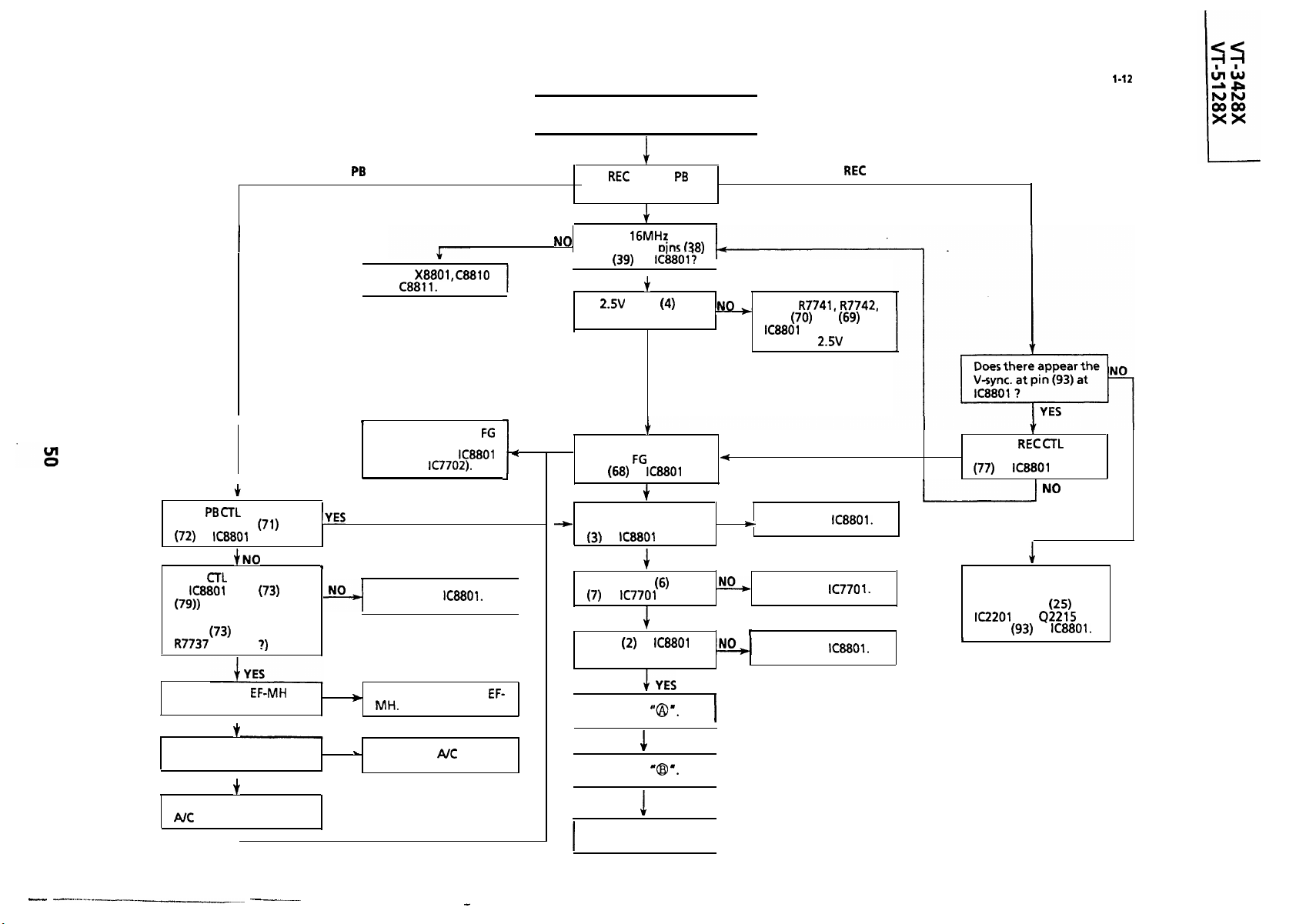
CAPSTAN SERVO TROUBLESHOOTING
Capstan servo does not function.
I
I
FLOW CHART NO. 1-12
A
0
I
I
Does
appear at pins (71) and
,
Does
of
(Does the noise appear
at pin (73) when touch
signal
of
amplifier circuit
(pins (73) to
by hand
?
Only
mode inoperative.
Check
and C8811.
I
Check the capstan
signal line between EC
connector and
(through
I
Replace
Are
and /or
mode inoperative ?
YES
Is there
oscillation at
.
I
and
Is 2.5V at pin
MC connector ?
NO
Does there appear the
capstan
pin (68) of
Is there capstan
r
control signal at pin
of
Are pins(S),
of
Is pin
normal ?
of I&801:!
I
YES
of
YES
signal at
YES
?
YES
and
normal ?
YES
of
NO
Check
pins
up to the 2.5V line.
Only
and (69) of
and all the way
Replace IC8801.
Replace
Replace IC8801.
mode inoperative.
Is there
YES
signal output at pin
Check the composite
sync. signal line
between pin
to pin
B
0
of
?
and Q2215 up
of
of
Is the harness
normal ?
Does the A/C head
operate normally ?
Adjust the height of the
head.
I
YES
I
YES
NO
NO
Replace the harness
Replace
--
head.
Check
I
Check
I
In case of NO GOOD
Replace the capstan
motor.
I
I
Page 51

VCR RECORDING MODE
No record.
FLOW CHART NO. 1-13
VCR RECORDING MODE (CHROMA)
Record Is In black and white ( E-E
FLOW CHART NO.
mode
Is there a signal at pin (38)
of
YES
Is there a signal at pin
of
Is there a signal at pin
of
IS
pin
level ?
I
YES
of 1~33019V
YES
Are there Y/C data and
clock signals at pins (14)
and
recording
NO
NO
NO
Is there
of
Check pin
and signal line.
of
when
at pin
YES
of
?
and
NO
Check the
Check the signal line all
the way up to pin
of
Check the
line.
line.
9V
Are there
clock signals at pins (14)
and
recording starts ?
,
Is there a signal at pin (2)
of
YES
Is there a signal at pin
of
,
YES
NO
and
Is there
L
I
data and
of
when
YES
5Vat
7
of
YES
SW. pulse at pin
YES
NO
signals from
,
I
ABNORMAL
Check data and clock
Check the signal line all
the way up to pin
the
of
SW. pulse
I
1
Replace
.
Page 52

VCR PLAYBACK MODE (LUMINANCE) TROUBLESHOOTING
No Playback.
Are there
clock signals at pins (14)
and
of
data and
YES
1
FLOW CHART NO. 1-15
VCR PLAYBACK MODE (CHROMA) TROUBLESHOOTING
Playback
Are there
when playback starts?
black and white.
I
data and
FLOW CHART NO.
Is there at pin
3
of
YES
I
I
I
Check and
harness from
to .
El
Is there
I
Is there
pin (20) of IC330 1 ?
I
I
I
I
Check peripheral circuit
Check pin
?
Check
at pin
YES
SW. Pulse at
YES
connector
I
NO GOOD
and
of
of
of
I
NO
I
I
I
I
Check the
line.
Check video head and/or
replace
SW. pulse
Is there a signal at pin (15)
I
of
is there a
of
I I
Is there a
of
I
Is there
pin
Is there a
pin (7) of El connector ?
Check the signal line of the
TV circuit.
I
?
of
?
YES
YES
at pin
YES
signal at
YES
YES
?
signal at
1
Check the pin
ND
(Bias line) and peripheral
circuit of
Check
I
Is there
of
Check the signal at pin
of
(Frequency,
of
line all the way up
SW. at pin
?
YES
?
MHz)
I
.
is
NO
ABNORMAL
Check
I
Check the chrome
rotation line.
Check Q22
signal line.
and the
I
I
Page 53

Is there a signal at pin
of
I
YES
I
NO
VCR E
E MODE TROUBLESHOOTING
No E- E signal.
Check the harness from
I
to
El
and input signal line.
FLOW CHART NO.
VCR SOUND TROUBLESHOOTING
I
Sound is not heard
I
I
I
No Sound
(
I
Sound is heard
But audio
I
is not
Is there an Audio
Signal at pin
1
(
FLOW CHART NO.
,
of
YES
NO
Is there a signal at pin
of
Check
connector.
I
YES
and El
Is there Bias Oscillator
Is there an Audio
Signal at pin
Is there
and
I
I
at pins
of
Replace
YES
YES
7
I
Check the
line.
Check the
pin
Check
line.
I
Replace
t
Check the signal line
from TV mother
of
of
NO
level at
in
and the
Is there an Audio
Signal at emitter of
Is there an Audio
Signal at pin
El
YES
ES
of
I
I
I
.
YES
Y
.
connector
YES
signal at pin (6) and
pin
of
Oscillator)
line between pin
Check pins
of
(Bias
and Audio
1
NO
of
Check the Audio mute circuit;
h
Check
Is there an Audio
Signal at pin
Is there an Audio
Signal at pin
I
Check the
pin
mode.
Check the signal line
between pin
of
and peripheral parts.
of
YES
of
YES
level
and
of
in
and
NO
I
at
I-
Check the signal line to the TV main
I
Page 54
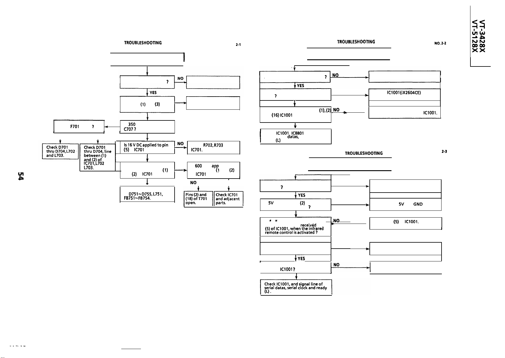
TROUBLESHOOTING OF TV SECTION
TV
I
Set not operating
TABLE
FLOW CHART NO.
KEY-IN
Key-in input for VCR is not received.
I
FLOW CHART
I
NO
Is
blown
YES
and
Is AC cord connected
Is AC applied to line
between
A-connector ?
NO
Is
Does pulse waveform
exist at line between
and
I
Check secondary circuits
of
and
V DC applied to
of
?
of
YES
YES
YES
?
of
NO
I
Check
Is 600 V DC ap lied to
NO
line between
of
I
I
Connect AC cord.
AC cord broken.
and
and
?
I
YES
I
Is the key switch in good contact
Is there short-circuit in the key
input
Are signals received at pins
and
activated 7
Check
line of serial datas, serial clock and
ready
Does the infrared remote control
function
Is
applied at pin
remote control receiver
IS
L
of the receiver and
$-YES ,
Is fluorescent lighting enough
away from the set ?
Is there short-circuit in the key
input or
I
I
when the key is
YES
,
and signal
.
INFRARED WC
No operation is possible from the
infrared remote control.
I
of the
pulse given out of pin (I)
YES
at pin
Check the switch contact.
NO
Check
switches for poor soldering.
Check key lines to input of IClOOl.
I
NO
NO
NO
Reposition the set not to be
, I
Replace the infrared remote
control as required.
Check pin
receiver.
exposed to strong light.
.
Check key input terminals.
I
FLOW CHART NO.
I
and
of IClOOl. and /or
and
lines.
I
I
I
.
--- --- ----
Page 55

TV TROUBLESHOOTING TABLE
I
NO RASTER
Normal
]
I I
I
,
I
FLOW CHART NO. 2-4
Replace the Fuse
I
Circuit to be checked:
TUNER
noise increases but no
signal is received
Is there a signal at pin (8)
of
gain
power source
I
Check
NO PICTURE, NO SOUND
I
Does the noise level increase at max,
Contrast, Brightness, and Sound Control ?
of
?
YES
and adjacent parts
h
FLOW CHART NO. 2-5
Is there a
signal at
of
adjacent parts.
Check Tuner AGC.
YES
Check
--------
-----
-___
Check the IF
Pack.
Check
line.
Page 56

NO VERTICAL SCAN
I
pin
bias check.
Normal
I
FLOW CHART NO. 2-6
NO PLAYBACK SOUND
I
Check the TV: TROUBLE
SHOOTING ‘NO SOUND’.
I
FLOW CHART
Check the CRT connector
,
--
Check
adjacent parts.
check
Normal
and adjacent parts.
and
NO SOUND
NO
Does waveform appear at
pin(8)oflC302?
I
I
Check speaker.
NO PLAYBACK PICTURE
I
Abnormal
I
I
I
I
FLOW CHART
FLOW CHART NO. 2-6
Circuits to be checked:
and its Adjacent Circuit
Output
(PAL
Check
adjacent circuits.
and its
I
I
Check 0851 and its
adjacent circuits.
Is the white balance
properly adjusted
Readjust the white
balance.
Check Q853 and its
I
adjacent circuits.
I
FLOW CHART NO.
I
I
I
I
Page 57

OVERALL SCHEMATIC DIAGRAM
I
H
G
FULL
ERASE HEAD
F
AUDIO CONTROL HEAD
VIDEO HEAD
I76GE
VT-5128X
I
E
LOADING MOTOR
I GE
D
I
I-
‘I---
,-
I
I
C
I
I
I
I
I
I
I
I
B
DRUM MOTOR DRIVER
DRUM MOTOR
I I24GE
r
AT sv
I
I
I
I
A
I
I
1
I
2
3
I
4
5
I
6
Page 58

I
I
I
I
X
t
i
I
I
DEFLECTION YOKE
I
X
IN
I
I
I
I
I
I
I
I
I
I
I
I
I
I
I
I
I
I
I
I
I
I
I
I
I
I
I
I
I
I
I
I
I
WITH -
IONS
I
7
8
I
9
I
I
I
Page 59

CHASSIS LAYOUT OF TV SECTION
H
I
PC
cl
G
El
II
cl
0
0
.
0
F
1
0
I
t
E
. - .
I
I
0
0
D
0
I
IF
0
1
0
0
0
1
VIDEO
C
AUDIO
OUT OUT
l
B
A
n
1
2
I
3
I
4
I
5
I
I
6
Page 60

1 01r
0
0
0
0
cl
cl
U
7
I
8
I
POWER
9
I
I
cl
I
I
Page 61

BLOCK DIAGRAM OF TV SECTION
I
R-Y.
B-Y.
AMP.
--(H-SYNC
.
I
I
( H-SYNC/H-FLY IN
I
1
I
2
I
. .
I
3
I
4
I
5
I
6
I
Page 62

VIDEO
AMP.
VIDEO SW.
AUDIO AMP.
I
AUDIO
AMP.
I
IF PACK
I
I
I
J
7
I
8
I
9
I
I
I
I
Page 63

BLOCK DIAGRAM OF TV SECTION
I-
I
VIDEO OUTPUT
CUT OFF
POWER
I
I
I
I
RELAY SW.
ON/OFF
SW ON/OFF
ERROR
DETECT
I I
I
I
PHOTO
I
COUPLER
POWER
I
1
I
2
I
3
4
I
5
I
6
Page 64
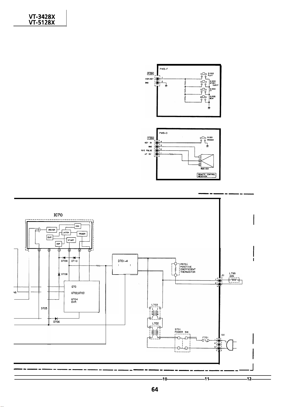
VCR-KEY
POWER SW-R/C
---F-----P-----P---
POWER CONTROL
I
START
RECTIFIER
I
ERROR AMP.
LATCH.
I
------
I I
I
I
I
I
I
I
I
I
I
I
I
I
I
I
I
I
I
1
I
I
I
7
I
8
I
9
I
I
I
I
Page 65

DESCRIPTION OF TV SECTION
SCHEMATIC DIAGRAM
SAFETY NOTE:
DISCONNECT THE AC PLUG FROM THE AC OUTLET BEFORE
PARTS.
POTENTIAL SHOCK HAZARDS WHEN THE CHASSIS IS
OPERATING.
IMPORTANT SAFETY NOTICE:
BE SURE TO USE GENUINE PARTS FOR SECURING THE SAFETY
AND RELIABILITY OF THE SET.
PARTS MARKED WITH (
FOR MAlNTAlNING THE SAFETY OF THE SET. BE SURE TO
REPLACE THESE PARTS WITH SPECIFIED ONES FOR
MAINTAINING THE SAFETYAND PERFORMANCE OF
SERVICE PRECAUTION:
THE AREA ENCLOSED BY THIS LINE(
DIRECTLY CONNECTED WITH AC MAINS VOLTAGE.
WHEN SERVICING THE AREA, CONNECT AN ISOLATING
TRANSFORMER BETWEEN TV RECEIVER AC LINE TO
HAZARD OF
) ARE IMPORTANT
IS
CAUTION:
This circuit diagram is original one, therefore there may be a
slight difference from yours.
NOTES:
The unit of resistance “ohm
=
ohms, M =
resistors are
watt, unless otherwise
noted.
The unit of capacitance
=
The values in parentheses are the ones in the
mode; the values without parentheses are
the ones in the
mode.
is omitted.
Meg ohm).
is omitted.
VOLTAGE MEASUREMENT CONDITIONS:
DC voltages are measured between points
indicated and chassis ground by
AC
supplied to unit and all
controls are set to normal viewing picture
unless otherwise no ted.
Voltages are measured with
with
B&W or
WAVEFORM MEASUREMENT CONDITIONS:
87.5% modulated
is fed into tuner.
bar signal
Page 66

SOLID STATE DEVICE BASE DIAGRAM
VIEW
1 3
1
1
1
0
0 0
BASE
L
COLLECTOR
C E
1
9
1
1
9
Page 67

1 AC: l.OVp-p
0
DC : 5.0 V
0
6
AC :
DC:
0
2AC:
0
7
AC : 2.2 Vp-p
WAVEFORMS (VT-3428X)
0
3
DC
AC: 1.7Vp-p
:
V
0
DC :
8
AC
DC:V
V
:
0
0
4
AC: 1.7Vp-p
DC :
9 AC : 50 Vp-p
DC:
0
5AC:
DC
:
0
AC :
Vp-p
0
I
I
I
I I I I I
AC :
0
AC:
DC:
0
AC:
DC:
0
AC: 8OVp-p
DC:
Page 68

WAVEFORMS
28X)
AC :
0
1
Vp-p
DC : 5.0 V DC : 3.2 V
0
I
0
I I I I I
AC :
0
I I I-
Vp-p
2 AC: 1.3Vp-p
7
AC :
Page 69

MODEL VT-3428X SCHEMATIC DIAGRAM: Mother Unit
TO PWB-E
I
I
I
I
I
I
I
2
I
3
I
4
I
5
6
Page 70

1
I
I I
PWB-E
ii i
I
I
Page 71

MODEL
I-
H
F
SCHEMATIC DIAGRAM: CRT Socket,
E
POWER
D
TO
C
TO
MOTOR
“CR
3
I I
I I
A
1
I
2
I
3
I
4
I
5
I
6
Page 72

VCR-Key
and
Power SW, R/C Unit
NOTE:. I. THE UNIT’ OF RESISTOR
ALL RESISTORS ARE I/BWATT. UNLESS OTHERWISE NOTED.
ALL CAPACITORS ARE
IO00 OHMS.
IS OMITTED
UNLESS OTHERWISE
TO PWB-A
TO PWB-A
-o--p7
--m-
I
8
I
9
I
I
Page 73

MODEL VT-5128X SCHEMATIC DIAGRAM: Mother Unit
H
G
EEPROM
F
TO PWB-E
E
TO
D
C
r
B
A
I
2
I
3
4
I
5
I
t
6
Page 74

1
PWB-E
7
I
8
I
9
I
I
I
I
Page 75

MODEL
--
TO PWB-A
SCHEMATIC DIAGRAM: CRT Socket,
TO PWB-A
TO PWB-A
POWER
I
1 I
2
3
I
4
I
5
I
I
6
Page 76

and
Power SW,
‘NOTE: I. THE UNIT OF RESISTOR
IO00 OHMS.
ALL RtSISTORS ARE I/BWATT.UNLESS OTHERWISE NOTED.
ALL CAPACITORS ARE
R/C Unit
OHM
IS OMITTED
UNLESS OTHERWISE
TO PWB-A
TO PWB-A
VCR-KEY
I OPWBFB732PEZZ
Page 77

. . . . . . . . . . .... . .. . .... . .. . . . . . . .
.
Infrared Remote Control Unit
1
I
2
I
3
I
4
I
5
I
6
1
Page 78

IF-Pack Unit
l
1
I
2
I
3
I
4
5
I
6
1
Page 79

CHASSIS LAYOUT OF VCR SECTION
II
VIDEO OUT
PB CHROMA
P
GND
I
.
0
cl
i
J
I’
END SENSOR
SENSOR
Page 80

I-----l
I
I BIAS(+)
I
I
I
CASSETTE
LED
cl
CAM SW A
T V REEL SENSOR
EC
I
I
START
SENSOR
HEAD SWITCHING
I
ED
UP
VOLUME
A
NON
7
UP
I
CH
A
8
I
POWER
WAKE-VP
.I
I
9
TIMER
I
CHILD LOCK
I
I
Page 81

BLOCK DIAGRAM OF VCR SECTION
H
OVERALL
DIAGRAM
G
F
------I
L--
IEC
E
VIDEO s1ouAL
D
a
3
a
I
*-
3
C
a
B
A
1
I
2
I
3
I
4
I
5
I
6
Page 82

I
I
7
I
8
I
9
I
I
I
Page 83

BLOCK DIAGRAM OF VCR SECTION
SERVO PROCESS BLOCK DIAGRAM
r----------d
I
I
I
I
I
I
1
I
2
I
3
I
4
I
5
I
6
Page 84

1
I
I
7
I
8
I
9
I
I
1
Page 85

BLOCK DIAGRAM OF VCR SECTION
--------
1
I
2
I
3
I
4
I
5
I
6
Page 86

I
n
SAFETY DEVICE BLOCK DIAGRAM
a
I
I
I
7
I
8
I
9
I
I
I
I
Page 87

I
I
I
I
m
I
I
MAD
MAO
I
I
ERASE
PROCESS
0
‘CC
BIAS
+
,
Page 88

AT SV
SYSTEM CONTROLLER
MANUAL SYSTEM IS
TV.
I 37PIN
FROM
COMPOSITE SYNC.
MC
FROM CAPSTAN MOTOR
FROM CTL HEAD
2
I
EC
V-SYNC.
SEPARATOR
CAP.
SHAPER
4
-u-u-
AMP
CTL
3OHr
AUTO SYSTEM IS TRANSFERED
SYS-CON DATA TO TV.
GENERATOR
TO
VIDEO
AUDIO
LPfHl
AUTO SYSTEM SELECT
BLOCK
Page 89

BLOCK DIAGRAM OF VCR SECTION
H
VIDEO SIGNAL FLOW BLOCK DIAGRAM
G
F
I
E
D
C
B
A
1
I
2
I
3
I
4
I
5
I
6
Page 90

7
I
8
I
9
I
I
I
I
Page 91

DESCRIPTION OF VCR SECTION
SCHEMATIC DIAGRAM
SAFETY NOTES:
DISCONNECT THE AC PLUG FROM THE AC OUTLET
BEFORE REPLACING PARTS.
SEMICONDUCTOR HEAT SINKS SHOULD BE REGARDED
AS POTENTIAL SHOCK HAZARDS WHEN CHASSIS
OPERATING.
NOTES:
The unit of resistance “ohm
M = 1 Meg ohm).
All resistors are watt, unless otherwise noted.
The unit of capacitance “F’is omitted
The values in parentheses are the ones in the
the values without parentheses are the ones in the
mode.
VOLTAGE MEASUREMENT CONDITIONS:
DC voltages are measured between points indicated and
chassis ground by VTVM, with
supplied to unit and all controls are set to normal
viewing picture unless otherwise noted.
Voltages are measured with
signal.
WAVEFORM MEASUREMENT CONDITIONS:
percent modulated colour bar signal is fed into
tuner.
CAUTION:
This circuit diagram is original one.
a slight difference from yours,
is omitted
Therefore there may be
=
p =ppF).
B & W or
ohm,
mode;
Page 92

WAVEFORMS
tovp-p
P In
Y/C
P In
COMPOSITE SYNC.
SERVO
CAPSTAN FG
P In
V :
SERVO
P In
CHROMA
P In
P In
P In
AUDIO
DRUM FQ
V :
P In
H/A H/A
P In
SERVO
.(REO)
IC3301
AUDIO AUDIO AUDIO
P In
SYSTEM
CONTROLLER
CLOCK
Ii:
P In
V :
P In
SERVO SERVO
P In
Page 93

--SCHEMATIC DIAGRAM: VCR Unit-l
H
G
F
TO SYSTEM CONTROL.SERVOWCRI
E
.
C
B
A
1
I
2
3
I
4
I
5
I
6
Page 94

3
7
I
8
9
I
I
I
I
Page 95

SCHEMATIC DIAGRAM: VCR Unit-2
JLOADING MOTOR
w3
I
2
I
3
VOLTAGE SW
I
4
I
5
LED TIMER CHILD
I
LED DRIVE
6
DRIVE
LEO DRIVl
Page 96

CIRCUIT
.
I
I
7
I
8
I
9
I
I
I
I
Page 97
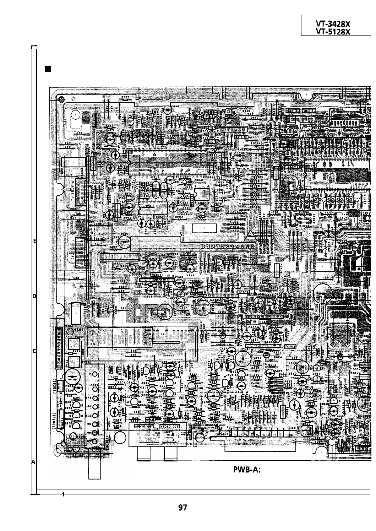
PRINTED WIRING BOARD ASSEMBLIES
TV SECTION
H
G
F
8
I
2
I
3
I
4
I
5
I
6
I
Page 98

1
Power SW, R/C Unit
(Wiring Side)
Unit (Wiring Side)
7
I
8
I
9
I
I
I
I
Page 99

TV SECTION
H
G
F
E
Power Unit (Wiring
D
C
B
A
I
2
I
3
I
4
I
5
CRT Socket Unil
I
6
Page 100

Side)
7
I
8
I
9
I
I
I
 Loading...