

Page 1
VL-Z7U/Z75U/Z8U
Supplement
SERVICE MANUAL
S93I2VL-Z7U//
SUPPLEMENT
LIQUID CRYSTAL DISPLAY CAMCORDER NTSC
VL-Z7U
VL-Z75U
MODELS
This Supplement has been issued to correct typos, and improve poor explanations, which were found
in the already issued Service Manual (S43Z2VL-Z7U//) for page p.43 and p.44 this model. Please refer to
this document for your better understanding.
CONTENTS
(5)Camera adjusting procedure............................................................................................................... 2
10-2-4.Adjusting procedure ..................................................................................................................... 3
VL-Z8U
Page
SHARP CORPORATION
This document has been published to be used for
after sales service only.
The contents are subject to change without notice.
1
Page 2
10-2-4. Adjusting procedure
VL-Z7U/Z75U/Z8U
Supplement
Item
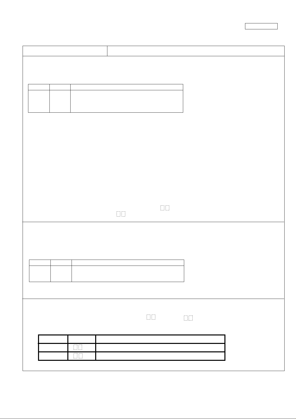
(1) Adjustment of auto focus
The following adjustments are performed automatically by establishing the auto focus adjustment mode and writing the following
data at address "13FD" sequentially. The adjustment items are as shown in the table below. When an adjustment is completed
normally, data "FF" is written, which should be confirmed before proceeding to the next adjustment.
Address Data Adjustment item
13 F D 0012 Adjustment of wide end
0008 Adjustment of tele end focus ∞ position
0006 Adjustment of wide end focus ∞ position
000D Adjustment of zoom tracking
Note 1: During the adjustment of ∞ position, a subject should be shot actually. Make this adjustment while shooting a subject with
a clear-cut outline. In the case of the adjustment of tele end focus ∞ position in particular, if it is performed without shooting
a distant subject actually, the ∞ position will not be adjusted properly.
Adjustment of wide end focus ∞ position: 3 m or more
Adjustment of tele end focus ∞ position: 50 m or more
Note 2: In the case of the adjustment of ∞ position, the depth of field is important in insuring accuracy. If the depth of field is deep,
the ∞ position may be adjusted improperly the subject hardly falls out of focus. Make this adjustment with the depth of
field being shallow (the iris opened).
It is possible to open the iris using the high-speed shutter.
1. Establish the normal mode.
2. Call the V-V adjust sports mode in normal operation. (Refer to the instruction manual.)
3. Display "CAM ADJ" by using the remote control for servicing.
4. Establish the auto focus adjustment mode.
5. Perform the adjustment of ∞ position.
6. After the completion of the adjustment of ∞ position, set the V-V adjust back to the off position.
After exiting the auto focus adjustment mode (writing data " FF" at address "13FE"), establish the camera signal
system adjustment mode (writing data " 00" at address "0000").
Adjustment method
(2)Basic adjustment of iris
It is performed to adjust the operating point of the hall element installed in the iris meter.
The following adjustments are performed automatically by writing the following data at address "13FD" sequentially in the camera
signal system adjustment mode. The adjustment items are as shown in the table below. When an adjustment is completed
normally, data "00FF" is written automatically.
Address Data Adjustment item
13 F D 0009 Adjustment of hall offset
000A Adjustment of iris offset
000B Adjustment of iris close
(3)Adjustment of black balance/Adjustment of A/F noise
This adjustment is performed automatically by writing data " 01" and data " 08" at address "0001". When the adjustment
is completed normally, data "00FF" is written automatically.
The adjustment item are as shown in the table below.
Address Data Adjustment item
0001 01 Adjustment of Tape-Mode black balance and A/F noise.
08 Adjustment of Card-Mode black balance.
3
Page 3

VL-Z7U/Z75U/Z8U
Supplement
COPYRIGHT © 2003 BY SHARP CORPORATION
ALL RIGHTS RESERVED.
No part of this publication may be reproduced,
stored in a retrieval system, or transmitted in
any form or by any means, electronic, mechanical,
photocopying, recording, or otherwise, without
prior written permission of the publisher.
Sep. 2003 Printed in Japan
In Japan gedruckt
Design and Production Information
Design : Japan
Production : Japan
SA. KD
SHARP CORPORATION
AV Systems Group
Quality & Reliability Control Center
Yaita, Tochigi 329-2193, Japan
4
Page 4

VL-Z7U/Z75U/Z8U
Supplement
(4) Camera signal system adjustment mode
In the camera signal system adjustment mode, the auto white balance function is stopped in order to adjust the camera. In this
mode, the white balance is set to the indoor mode and focussing is performed manually.
1) How to enter the camera signal system adjustment mode
Set the data value at address "0000" to " 00".
]
The camera signal system adjustment mode will be established.
*When the camera signal system adjustment mode is established, make adjustment according to "(5) Camera adjusting
procedure".
2) How to enter the normal mode
Set the data value at address "0000" to " FF".
]
The normal mode will be established.
]
Pressing "CONTINUE" key will make the display "CAM ADJ" disappear and make it possible to perform normal operation.
(5) Camera adjusting procedure
1. Adjustment of auto focus
2. Basic adjustment of iris
3. Adjustment of black balance/Ajustment of A/F noise
4. Rough adjustment of iris AE
5. Rough adjustment of white balance
6. Rough adjustment of color gain
7. Adjustment of white balance
8. Adjustment of indoor white gain
9. Adjustment of color gain
10. Adjustment of auto white balance adjustment
11. Adjustment of outdoor white gain
12. Adjustment of iris AE
* "1. Adjustment of auto focus" is performed in the auto focus adjustment mode. The other adjustments are performed in the camera
signal system adjustment mode.
(6) How to replace the gyro unit
2
1) When replacing the E
PROM on the main unit with the gyro unit kept unchanged
Because the gyro adjustment data is stored in the E2PROM, read the data at address "1064" and write it into the new E2PROM
after replacement.
2) When replacing the gyro sensor (RMC1001)
After replacing the gyro sensor with the specified one, write the following data at address "1064".
Ref No. Part code Address Data
RMC1001 Changed to RSNSGA005WJPZY 1064 01D0
2
 Loading...