

Sharp VL-Z400H-T,VL-Z500S-S,VL-Z400S-T,VL-Z500H-S,VL-Z500E-TVL-Z500E-S Service Manual
VL-Z400S-T/H-T
VL-Z500S-S/H-S/E-T/E-S
SERVICE MANUAL
S45T2VL-Z400S
LIQUID CRYSTAL DISPLAY CAMCORDER PA L
VL-Z400S-T
VL-Z400H-T
VL-Z500S-S
VL-Z400S/H
VL-Z500H-S
VL-Z500E-T
MODELS
In the interests of user-safety (Required by safety regulations in some countries) the set should be restored to its
original condition and only parts identical to those specified
be used.
VL-Z500S/H/E
CONTENTS
1. SPECIFICATIONS .............................................................................................................................. 2
2. PART NAMES .................................................................................................................................... 3
3. DISASSEMBLY OF THE SET ............................................................................................................ 4
4. MECHANISM ADJUSTMENT JIGS AND PARTS .............................................................................. 8
5. INSPECTION AND MAINTENANCE
ITEMS AND INTERVALS ................................................................................................................... 9
6. ADJUSTING AND CHECKING OF MECHANISM ........................................................................... 10
7. ADJUSTMENT OF RUNNING SYSTEM .......................................................................................... 13
8. ASSEMBLING OF MECHANISM SECTION AND PART REPLACEMENT
(DISASSEMBLING AND ASSEMBLING) ........................................................................................... 15
9. METHOD OF ADJUSTING THE ELECTRIC CIRCUIT .................................................................... 25
10.USEFUL TIPS ................................................................................................................................... 44
11.SIGNAL FLOW DIAGRAMS ............................................................................................................. 45
12.BLOCK DIAGRAMS ......................................................................................................................... 48
13.SCHEMATIC DIAGRAMS ................................................................................................................ 56
14.SEMICONDUCTOR LEAD IDENTIFICATION ............................................................................... 130
15.PRINTED WIRING BOARD ASSEMBLIES .................................................................................... 132
16.REPLACEMENT PARTS LIST ....................................................................................................... 149
17.PACKING OF THE SET ................................................................................................................. 172
VL-Z500E-S
Page
SHARP CORPORATION
1

VL-Z400S-T/H-T
VL-Z500S-S/H-S/E-T/E-S
1. SPECIFICATIONS
Recording System: 2 rotary heads, helical scanning system
Recording/Playback Time: 90 minutes (DVM60, LP mode)
Lens Filter Diameter: 30 mm
Built-in Microphone: Electret stereo microphone
Color Temperature Compensation: Auto white balance with white balance lock, outdoor or in door
Minimum Illumination: 2 lux* (with gain-up, F1.8)
Still Image Compression System: JPEG base line conformance
Still Image Recording Format: JPEG (Exif2.2)
Still Image Recording Medium: SD Memory Card, MultiMediaCard
Power Requirement: DC 7.4 V
Power Consumption: 3.4 W (during camera recording in Tape Camera mode using the viewfinder in Full
Operating Temperature: 0°C to +40°C
Operating Humidity: 30% to 80%
Storage Temperature: –20°C to +60°C
Dimensions (approx.): 82.9 mm (W) × 82.2mm (H) × 100.8 mm (D)
Weight (approx.): 480 g
Signal System: PAL standard
Cassette: Digital VCR Mini DV video cassette
Tape Speed: SP mode: 18.831mm/second
LP mode: 12.568 mm/second
Pickup Device:1/6" (4.2 mm, effective size: 3.0 mm) CCD image sensor
(with approx. 800,000 pixels including optical black,
effective pixels: 414,000 pixels)
Lens: 10 × optical zoom lens (F1.8, f=3.8-38.0 mm)
Monitor: 2.5" (6.4 cm) CGSilicon
Viewfinder: 0.16" LCD panel (with 113.578 pixels), slide type
USB Terminal: Mini-B type connector (USB 1.1 version)
DV terminal: 4 pin connector (i.LINK)
Auto mode with the DIS function on)
VL-Z400S/Z500S/E:
4.0 W (during camera recording in Tape Camera mode using the LCD monitor in
Full Auto mode with the DIS function)
VL-Z500H:
4.0 W (during camera recording in Tape Camera mode using the LCD monitorin
Full Auto mode with the DIS function and backlight in normal mode)
(without battery pack, lithium battery, video cassette, lens cap and card)
AC Adapter (UADP-A053TAZZ)
Power Requirement: AC 110-240 V, 50/60 Hz
DC Output: 10 V
Dimensions (approx.): 49.0 mm (W) × 27.5 mm (H) × 79.0 mm (D)
Specifications are subject to change without notice.
*Minimum illumination: Since there is no widely accepted testing procedure for determining minimum illumination
capability, lux ratings are comparable only between models from the same manufacturer.
2
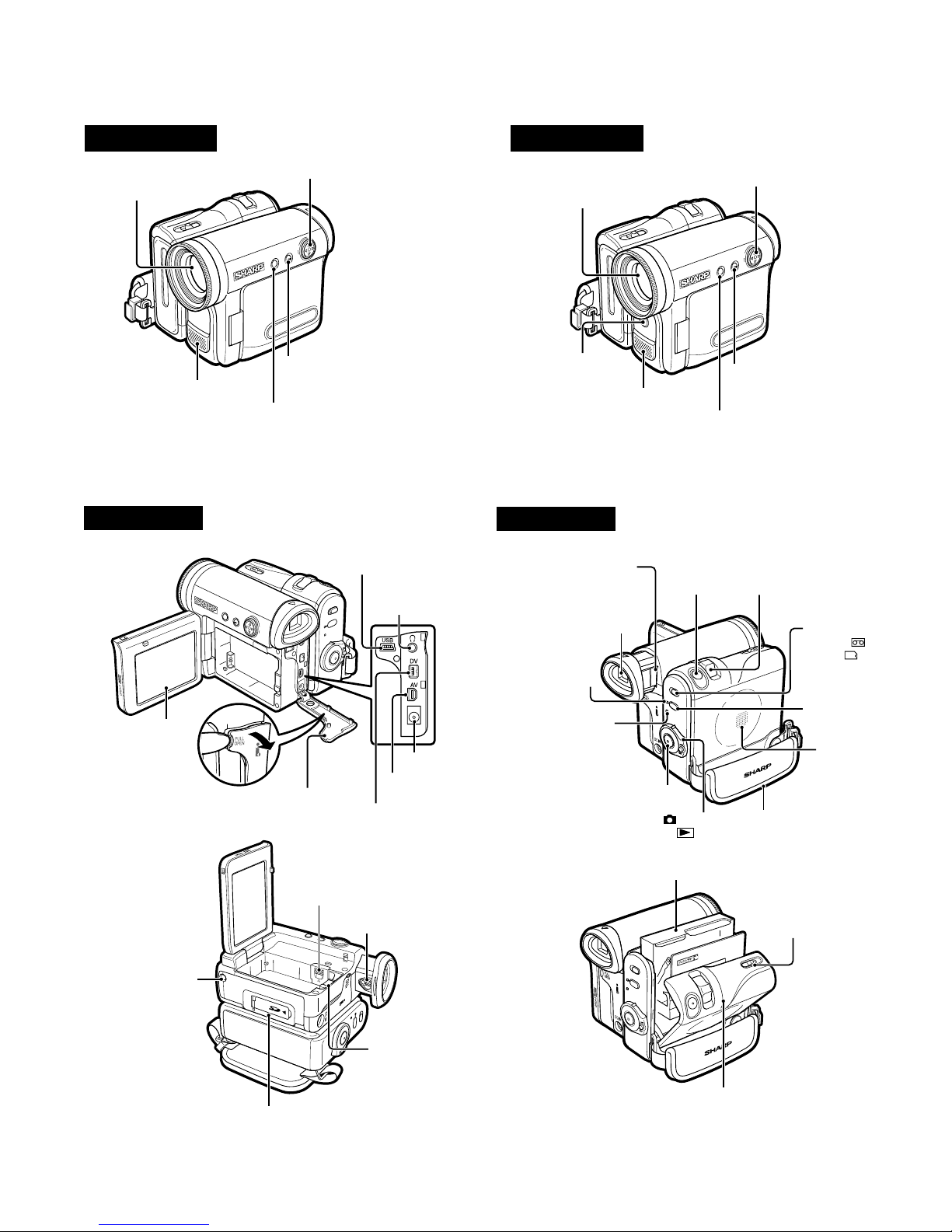
2. PART NAMES
VL-Z400S-T/H-T
VL-Z500S-S/H-S/E-T/E-S
Front view
Zoom lens
Stereo microphone
Left view
VL-Z400S/H
DISPLAY/MODE SET button/
LCD LAMP button
MENU button
Operation button
USB terminal
Earphones jack
Front view
Zoom lens
Built-in LED video
light
Stereo microphone
Right view
Window cleaning cover
Viewfinder
STANDBY indicator
VL-Z500S/H/E
MENU button
PHOTO button
Operation button
DISPLAY/MODE SET button/
LCD LAMP button
Power Zoom Wide angle/
Telephoto control/
VOLume control
Media Selection
switch ( Tape
mode/ Card
mode selection
switch)
LCD monitor
Tripod socket*
* When attaching a tripod
with a guide pin, do not
attach the pin to the bottom
of the camcorder.
Terminal cover
Lithium battery cover
Card slot cover
DC IN jack
AV terminal
DV terminal
Dioptre adjustment dial
Battery release
POWER/CHARGE
(RED) indicator
Record Start/Stop button
Power switch ( Camera
Recording mode/ Playback
mode select switch)
STANDBY button
Speaker
Hand strap
Cassette holder
Cassette compartment
door release
Cassette compartment door
3
VL-Z400S-T/H-T
VL-Z500S-S/H-S/E-T/E-S
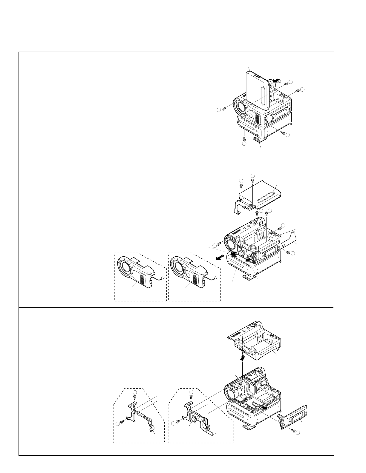
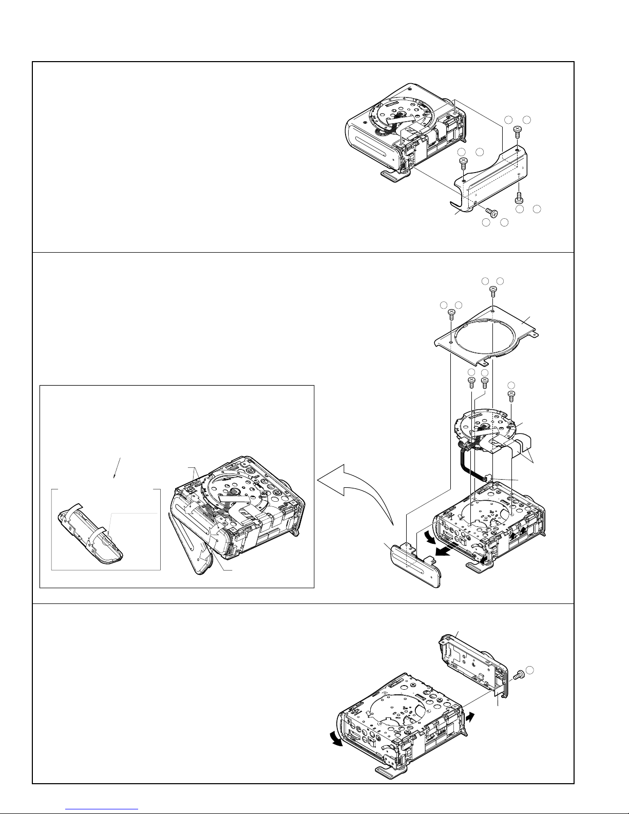
3. DISASSEMBLY OF THE SET
3-1. Procedure for disassembling the cabinet
Note: Before removing the cabinet, turn OFF the power and make sure that the battery is not connected.
1.
· Remove the screw ((s) XiPSF14P06000).
· Open the LCD panel 90 degrees and remove the two screws ((x) LXHZ0050TAFN).
· Remove the two screws ((c) XiPSN17P04000) and remove the
camera front cover by pulling it frontward.
s
LCD panel
c
Camera front cover
x
x
c
2.
· Disconnect the connector of the camera front cover.
· Disconnect the two LCD tilt FPCs of the LCD panel.
· Remove the two screws ((r) XiPSN20P08000) and remove the LCD
panel.
· Remove the screw ((p) LX-HZ0063TAFN) and screw ((q)
XiPSN17P06000) that hold the camera L cabinet, open the terminal
cover and remove the three screws ((b) XiPSN17P03000).
Camera front cover
VL-Z400 VL-Z500
Camera front cover
3.
· Disconnect the FPC and remove the camera L cabinet.
· Remove the screw ((c) XiPSN17P04000) and remove the camera
bottom cover.
· VL-Z400: Remove the tilt angle and remove the two screws ((a)
XiPSN17P02000).
VL-Z500: Disconnect the INNER LED FPC, remove the two screws
((a) XiPSN17P02000) and remove the INNER LED unit.
LCD tilt FPC
b
r
INNER LED Unit
(VL-Z500 only)
r
Connector
LCD panel
q
p
Camera L cabinet
b
Camera L cabinet
Terminal cover
b
a
a
VL-Z400
Tilt angle
a
a
INNER LED unit
VL-Z500
4
INNER LED
FPC
FPC
Camera
bottom cover
c
VL-Z400S-T/H-T
b
u
u
u
Mechanism reversion detection PWB unit
PWB mounting angle
VL-Z500S-S/H-S/E-T/E-S
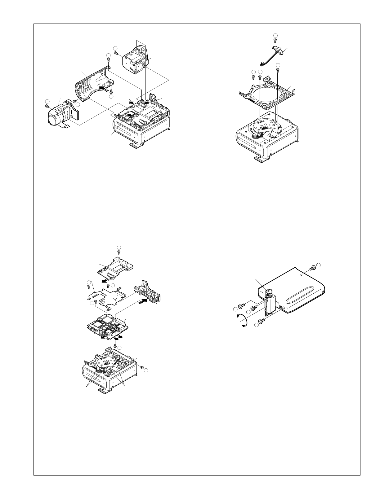
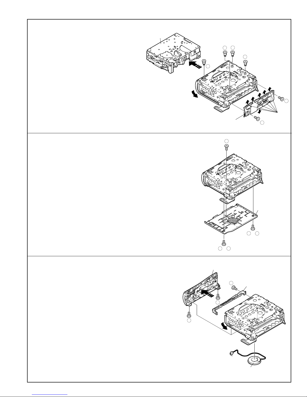
4.
b
x
Camera top cover
Camera unit
b
a
p
FPC(1)
FPC(2)
· Remove the screw ((x) LX-HZ0050TAFN), screw ((p) LXHZ0063TAFN) and screw ((a) XiPSN17P02000), remove the
camera top cover.
· Remove the screw ((b) XiPSN17P03000) from the camera
unit, disconnect the FPC (1), (2) and remove the camera unit.
· Remove the screw ((b) XiPSN17P03000), disconnect the
FPC (3) and remove the VF.
VF
FPC(3)
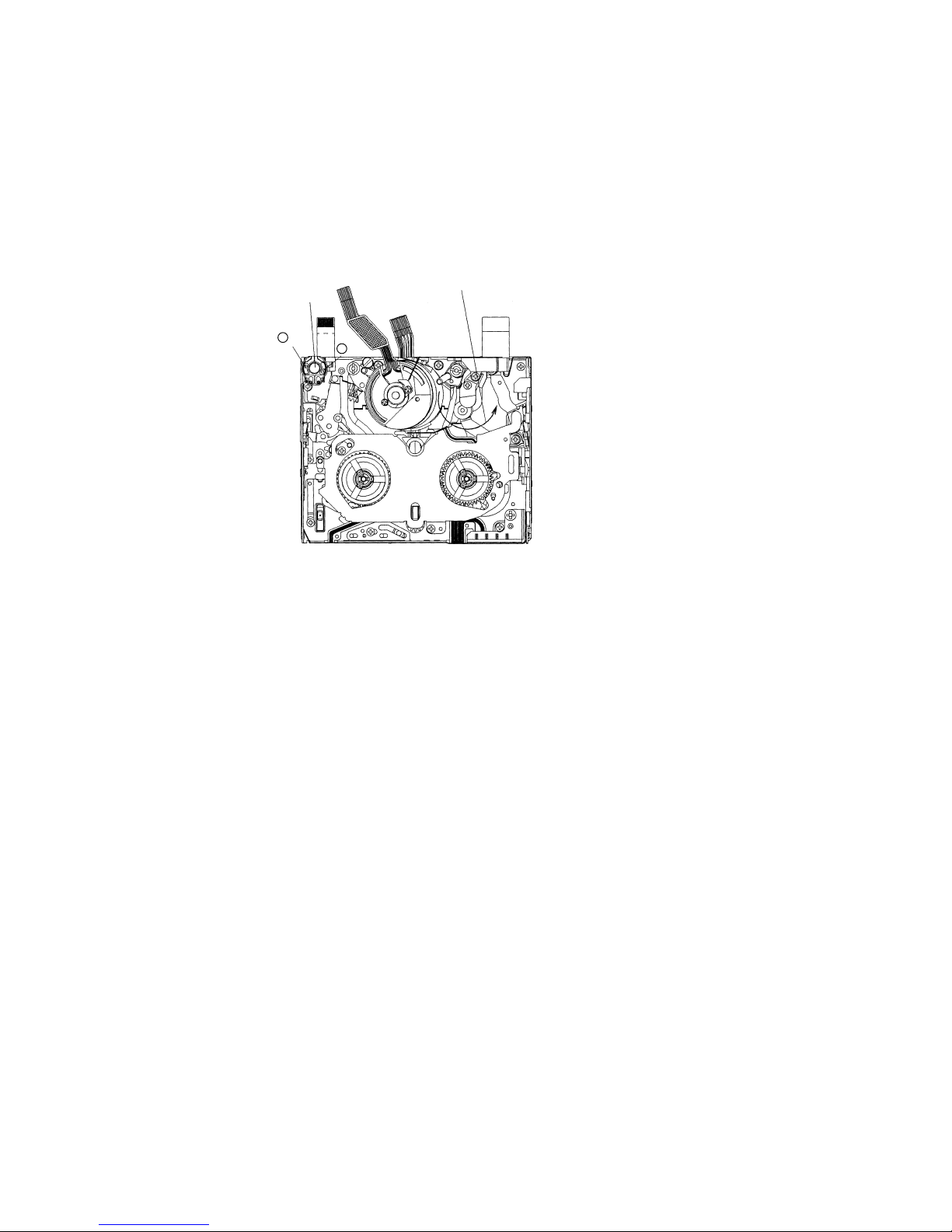
6.
· Remove the screw ((b) XiPSN17P03000) and remove the
Mechanism reversion detection PWB unit.
· Remove the three screws ((u) LX-BZ0221TAFC) and remove
the PWB mounting angle.
5.
Sub PWB unit
Heat release angle
b
b
· Disconnect the two connectors of the sub PWB unit and main
PWB unit.
Connector
x
b
Main PWB unit
x
PWB mounting angle
Tilt FPC
Terminal cabinet
x
7.
b
LCD tilt unit assembly
b
a
b
· Turn the LCD tilt unit assembly 90 degrees.
· Remove the three screws ((b) XiPSN17P03000).
· Remove the screw ((a) XiPSN17P02000).
· Remove the two screws ((b) XiPSN17P03000) from the heat
release angle, remove the screw ((b) XiPSN17P03000) from
the PWB unit and remove each unit.
· Disconnect the two FFCs of the main PWB unit.
· Remove the two screws ((x) LX-HZ0050TAFN), remove the
screw ((x) LX-HZ0050TAFN) form the PWB mounting angle
and remove the terminal cabinet.
5
VL-Z400S-T/H-T
VL-Z500S-S/H-S/E-T/E-S
3-2. Procedure for disassembling the cabinet
1.
· Remove the three screws Z500E-T: ((e) XiPSF17P03000) or Z400/
Z500S-S/H-S/E-S: ((b) XiPSN17P03000) remove the screw Z500ET: ((d) XiPSF17P02000) or Z400/Z500S-S/H-S/E-S: ((a)
XiPSN17P02000) and remove the VCR bottom cover.
2.
· Remove the two screws Z400/Z500S-S/H-S/E-S: ((b) XiPSN17P03000)
or Z500E-T: ((e) XiPSF17P03000) and remove the tilt cover.
· Remove the VCR front cover with the cassette cover opened.
· Disconnect the connector and two tilt FPCs, remove the three screws
((h) LX-BZ0220TAFC) and remove the camera tilt.
or
b e
VCR bottom cover
or
e
b
or
b e
or
e
b
or
b e
a d
or
Tilt cover
How to remove the VCR front cover
1. Remove the two couplings and turn the VCR front cover about 20 degrees in
the direction indicated by (1).
2. Turn the VCR front while sliding it in the direction indicated by (2) to disengage
the internal lug.
* If the VCR front cover is removed by turning it forcedly in the direction indicated
by (1), the internal lug may be damaged.
1
If the VCR front cover is removed
only by turning it in the direction
indicated
The internal lug
may be damaged
2
3.
· Remove the screw ((f1) XiPSF17P04000) with the cassette lid
opened, disconnect the operation PWB FFC and remove the VCR
operating cover.
VCR front cover
h
h
VCR operating cover
h
Camera tilt
Tilt FPC
Connector
f1
Operating PWB FFC
6
4.
k
a
a
w
w
w
Mechanism
Head amp PWB unit
FPC
· Disconnect the six FPCs of the head amp circuit board
unit.
· Remove the two screws ((a) XiPSN17P02000) and
remove the head amp PWB unit.
· Remove the three screws ((w) LX-BZA022WJFN) and
remove the screw ((k) LX-BZA023WJFD).
· Remove the mechanism with the cassette lid opened.
VL-Z400S-T/H-T
VL-Z500S-S/H-S/E-T/E-S
5.
· Remove the screw ((x) LX-HZ0050TAFN).
· Remove the two screws Z500E-T: ((d) XiPSF17P02000) or Z400/
Z500S-S/H-S/E-S: ((a) XiPSN17P02000) and remove the cassette lid.
6.
· Remove the two screws ((d) XiPSF17P02000).
· Disconnect the connector of the speaker while removing the Lid upper
cover with the cassette control lid opened.
· Remove the screw ((a) XiPSN17P02000) and remove the lock guide
cover.
· Remove the speaker.
a d
or
Lid upper cover
d
x
Cassette lid
a
d
or
a
Lock guide cover
d
Connector
7
Speaker
VL-Z400S-T/H-T
VL-Z500S-S/H-S/E-T/E-S
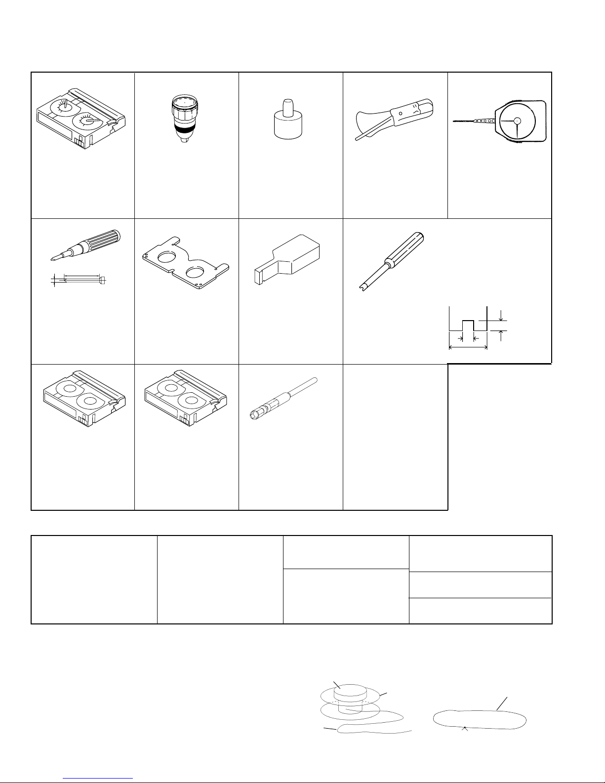
4. MECHANISM ADJUSTING JIGS AND PARTS
4-1. Mechanism checking and adjusting jigs
<Note: Order of descriptions>
Sketch
1. Name
2. Part code
3. Code
* Model number and usage
1. Cassette torque
meter for PB
2. 9DASD-1015
3. DB
* 1mN·m/1.5mN·m
50 or more
ø2
No.0 Phillips bit
No.00 Phillips bit
1. Torque driver
150mN·m
2. JiGTD1500RTDH
3. CB
1. Torque gauge
2. JiGTG0045
3. CN
* For measurement of VS-
REW winding torque
1. Master plane
2. 9EQMP-VLPD1
3. CL
* For checking of
1. Torque gauge head
2. 9EQTGH-DH5000
3. BW
For torque gauge shown
*
left
1. Height adjustment jig
2. 9DAHG-PD1
3. BZ
* For height adjustment
height of reel table
1. Alignment tape – (I)
2. VR3-GAZXS
3. CF
* Adjustment of running
system
(Linear signal)
1. Alignment tape – (II)
2. VR3-JPZQS
3. CG
* For adjustment of SW
point(Color bar signal)
* 90ADVC-TAPEPAL
available
1. Bit for hexagon nut
2. 95CM22001
3. BL
* For installation of Tu
guide nut
4-2. Parts for periodic inspection and maintenance
1. Oil
Cosmo Hydro HV22
2. 9EQ-OiL-HV22
3. AE
* Cosmo Oil Co., Ltd.
<How to make mechanism checking and adjusting jigs>
(1) Reel hub for back tension measurement (Fig.1)
1) Have the reel hub of a commercially available cassette
tape ready.(Disassemble the cassette tape and remove
the tape from the reel hub.)
2) Attach one end of a thread (having a length of about
20cm) to the reel hub using Scotch tape etc.
3)
Attach a weight of about 0.21N to the top face of the reel hub.
(2) Thread for pinch roller press force measurement
1) Have a commercially available thread having a length of
about 20cm ready.
1. Cleaning paper
2. JiGDUSPER
3. AP
* DUSPER ∑ (SIGMA)
(Ozu Co., LTD.)
with opposite side
distance of 3 mm
1. Dry grease CFD-409Z
* Sankei Chemical Co., LTD.
1. Grease
Molykote YM-103
2. 99FGREASEYM103
* Dow Corning
2) Tie both ends together to loop the thread.
Thread
8
1. Tension gauge 4N
2. JiGSG0400
3. BK
* For measurement of
pinch roller press force
1. Driver for height
adjustment
2. 9EQDRiVER-DH5
3. BC
<Miscellaneous>
(1) Vernier calipers
(2) Precision screwdriver
(Phillips head and slot-
ted)
(3) Long-nose pliers
(with thin tips)
(4) Tweezers
<Note: Order of descriptions>
Weight
Reel hub
Fig. 1
1. Dial tension gauge
2. 9DAPTG-10-10W
3. CA
* PTG-10
* For adjustment of guide
roller
* Bit shape
1. Name
2. Part code
3. Code
* Model number and usage
(see figure below)
Tolerance ± 0.1
2
1.4
Tip thickness 0.5
3
1. Cleaning liquid
Industrial ethyl alcohol
* Commercial item
1. Loctite adhesive (1401B)
* Three Bond
1. Ultrathin cotton swab
* Commercial item
Thread
Fig. 2
VL-Z400S-T/H-T
VL-Z500S-S/H-S/E-T/E-S
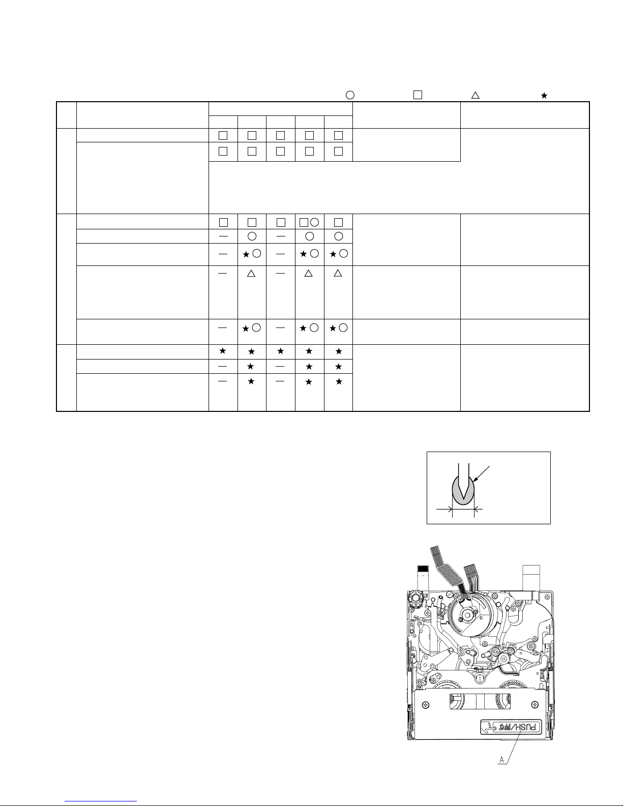
5. INSPECTION AND MAINTENANCE ITEMS AND INTERVALS
In order to maintain the quality of the mechanism section, perform the following maintenance and inspection. After repairing the
mechanism section, perform the following maintenance regardless of the number of hours of use by the user.
5-1. Maintenance and inspection list
Inspection and
maintenance location
Tape running section (See7-3.)
Drum section, Video head
(See 7-3.)
Running system
Pinch roller
Capstan motor (Timing belt)
Swing arm
S reel table, Tu reel table
Center gear boss
Relay pulley shaft
Driving system
Loading motor
Mode SW
Abnormal noise
PB and VS/R winding torque
PB, VS/R and loading back tension
S reel table unloaded torque
Performance check
Number of hours of use (h)
500 1,000 1,500 2,000 3,000
<Rollers>
• Replace if abnormal rotation or swing (large) is found.
<Others>
• Cleans the portions that come in contact with the tape (the lower
drum helical portion in particular). Use the specified cleaning liquid.
• • • Replace. • • • Clean. • • • Lubricate. • • • Check.
Symptoms observed at the
time of maintenance
• Block noise
• Clogging of head
• Damage to tape
• Tape not running
• Tape sagged
• Block noise
• Abnormal noise
• Abnormal noise
• Ejecting cannot be made.
• Mode cannot be set.
• Tape not running
• Tape sagged
• Damage to tape
• Abnomaly in reproduced
picture
[Oil] Cosmo Hydro HV22
[Grease] Molykote YM-103
Sankei Chemical CFD-409Z
Notes and remarks
Note:
If no envelope output is obtained
in spite of the video head being
cleaned, replace the drum
component.
(If the envelope output is normal,
refer to "10. USEFUL TIPS".)
• Replace if any abnormal
condition is found.
• Apply oil.
[Oil]
Cosmo Hydro HV22
Note:
Apply oil to the shaft and
lightly wipe it off with a cloth.
• Replace if any abnormal
condition (noise etc.) is found.
• If a part is out of spec, replace
it.
[Loctite adhesive] Three Bond 1401B
[Cleaning liquid] Industrial ethyl alcohol
5-2. Cautions in handling the mechanism
(1)Cut washers removed at the time of part replacement etc. should be
replaced with new ones without fail.
(2) Because no volume adjustment is available in this mechanism, cleaning or
part replacement should be performed if the setting is not satisfied.
(3) About oil
a) Be sure to use the specified oil. (If any oil other than the specified oil is
used, various troubles will occur.)
b) When lubricating the bearing, be sure to oil free from foreign particles
such as dust. (If oil in which foreign particles such as dust are mixed is
used, it will cause wear and seizure to the bearing.)
c) The term "One drop of oil" here means the amount of oil on the point of
a needle etc. shown in Fig.1.
(4) Repairing of circuits, final adjustment of running system, etc. should be
performed with the cassette controller assembly installed in the mechanism.
(5) When operating the mechanism singly, apply voltage to the loading motor
to drive it. The voltage between the terminals should be 3 to 4V DC. (Do
not apply external voltage to the loading motor with the mechanism
connected with the main circuit board. Doing so could cause a failure.)
(Turning the gears forcedly by hand may cause them to get damaged.)
When placing the mechanism singly, use an appropriate spacer so that the
capstan motor is not rubbed.
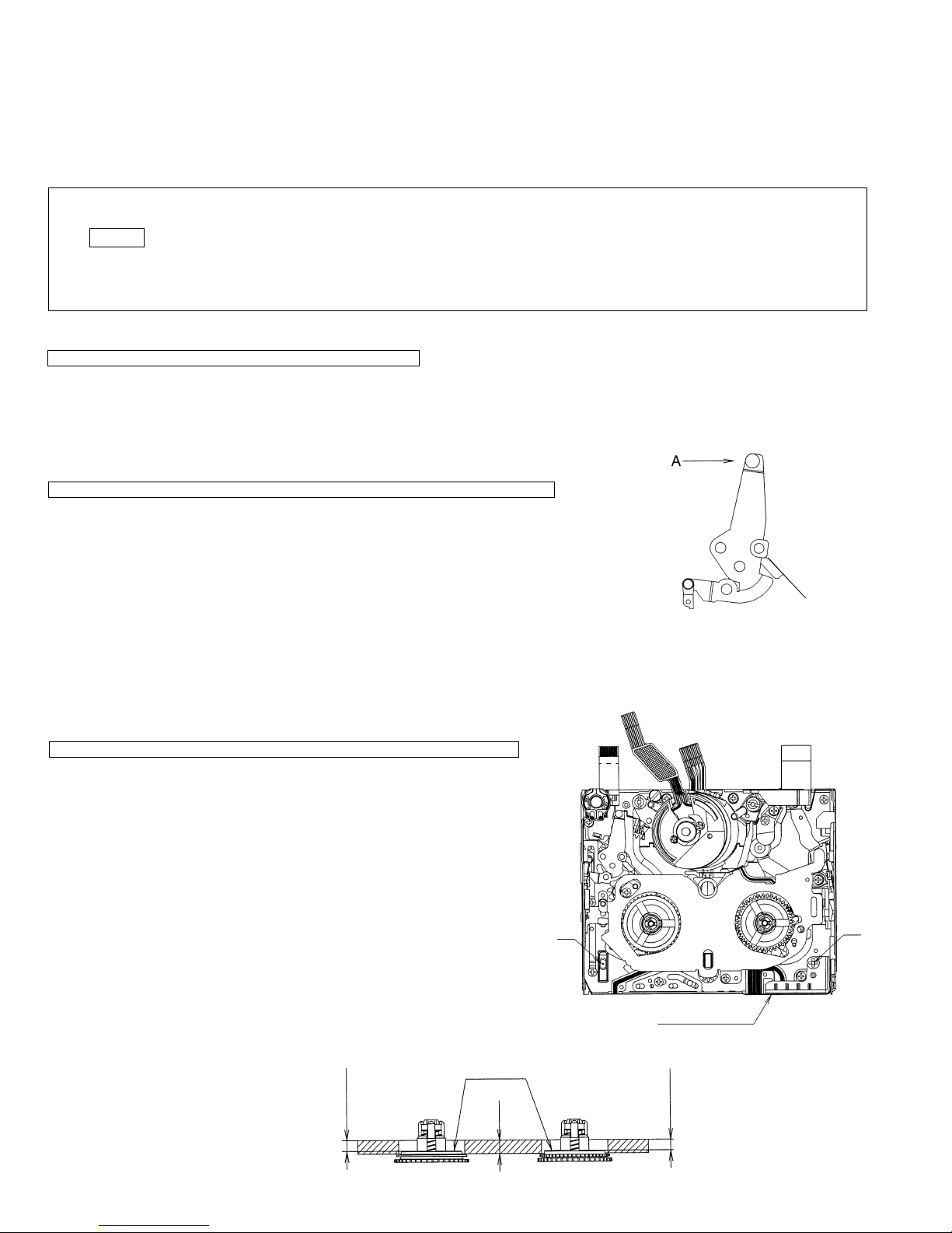
(6) When installing the cassette controller, push the portion indicated by "A" in
Fig.2. Do not push other portions.
(7) Take care not to deform the components of the mechanism.
Oil
Ø1.5 or less
Fig. 1
Fig. 2
9
VL-Z400S-T/H-T
VL-Z500S-S/H-S/E-T/E-S
6. ADJUSTING AND CHECKING OF MECHANISM
The items described here are relevant to the general on-site servicing (field service). This section does not cover adjustment and
replacement for which sophisticated equipment, jigs and techniques are required.
In order to maintain the initial characteristics of the mechanism, it is necessary to perform maintenance and inspection and also it is
essential not to damage the tape etc. In the case of an adjustment that requires a jig, be sure to use the specified jig.
<Caution>
(1) When adjusting and checking the mechanism, be sure to see that the power supply and the status are as indicated in
Caution on the title.
(2) Do not apply external voltage to the loading motor with the mechanism connected with the main circuit board. (Doing
so could cause a failure.)
(3) When running the tape, be sure to do so with the cassette controller assembly installed.
6-1. Checking of PB (REC) winding torque
AC adapter used, Cassette controller assembly installed
(1) Set the torque cassette with the cassette controller installed in the mechanism. In the SP record mode (or in the PB mode
if signals have been SP-recorded on the tape), check that the winding torque is within spec.
<Spec for PB (REC) winding torque>(If there is a torque ripple, read the center value.)
0.7+0.2/-0.05N·m, Ripple: 0.1mN·m or less
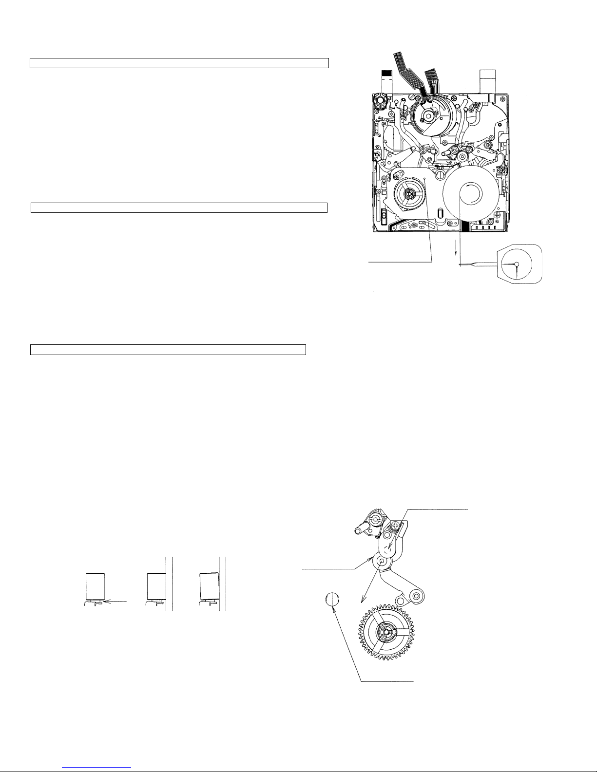
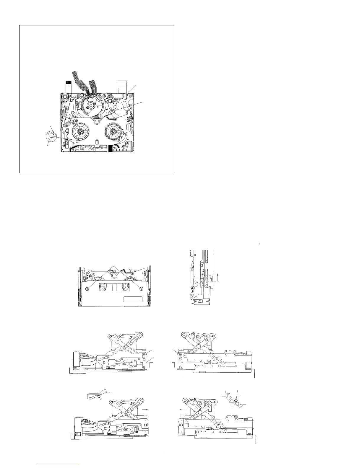
6-2. Checking of VS-REW winding torque
AC adapter used, Cassette controller assembly not installed (Mechanism only)
(1) Remove the cassette controller, turn ON the down SW while referring to 8-3, operate
in the test mode (T01) and select the VS-REW mode.
(2) Set the torque gauge in the S reel table, push the tip of the tension pole with your finger
in the direction shown by Arrow A to release the tension band, and check that the
winding torque is within spec. (Fig.1) (Do not apply the own weight of the torque
gauge or rotate it during measurement.)
<Spec for VS-REW winding torque>
(If there is a torque ripple, read the center value.)
1.5 ± 0.15N·m, Ripple: 0.15mN·m or less
(3) After checking the winding torque, remove the torque gauge and turn OFF the down
SW. The mechanism will automatically go into the standby mode.
Fig.1 How to release the tension
band when measuring the
VS-REW winding torque
6-3. Checking of height of reel table
3 to 4V DC, Cassette controller assembly not installed (Mechanism only)
(1) Remove the cassette controller. (Refer to 8-2.)
(2) Apply 3 to 4V DC to the loading motor while referring to 8-1 and select the
PB mode.
(3) Fit the holes of the master plane to the two guides (portions A and B) shown
in the Fig.2, taking great care not to allow master plane to strike the running
parts such as the drum and guide roller or the MIC contact.
(4) Using a pair of vernier calipers etc., measure the heights of the reel-supporting
faces of the S reel table and Tu reel table from the top face of the master plane
and check that the measured heights satisfy the set values. (Fig.3)
When measuring the height of the S reel table, push the tip of the tension
pole with your finger in the direction shown by Arrow A to release the tension
band. (Fig.1)
(5) If the measured height does not satisfy the set value, replace the reel table
and make checking again.
<Note> After replacement, select the L start mode (see 8-1) and check that the
reel table rotates smoothly.
2.4±0.1
Set value of height
of reel table
Reel-supporting face
(3)
Fig.3
10
A
MIC contact
Fig.2 Checking of reel table
2.4±0.1
Set value of height
of reel table
B

VL-Z400S-T/H-T
VL-Z500S-S/H-S/E-T/E-S
6-4. Checking and adjusting of tension pole position during
REC (PB)
3 to 4V DC, Cassette controller assembly not installed (Mechanism only)
(1) Checking
Check that the tension pole is located in the prescribed position as shown in Fig.4
at the start of a 60-minute tape.
If the tension pole is not located in the prescribed position, take out the tape and
make adjustment according to the procedure shown below.
(2) Adjusting (See Fig.4.)
1. Select the PB mode without setting a tape.
2. Slightly loosen the screw 1 (to such an extent that the T band adjustment base
2 can be moved.)
3. If the tension pole is dislocated inward from the prescribed position, shift the
T band adjustment base 2 in the direction shown by Arrow (A). If it is dislocated
outward from the prescribed position, shift the T band adjustment base 2 in the
direction shown by Arrow (B). Then fix the T band adjustment base 2 with the
screw 1.
(For how much the T band adjustment base is to be shifted, refer to Fig.4.)
4. Check the tension pole position as described in "(1) Checking" above.
5. If out of position, make readjustment.
6-5. Checking and adjusting of REC (PB) back tension
torque
AC adapter used, Cassette controller assembly installed
(1) Checking
Set the torque cassette (SD-1015). In the SP record mode (or in the PB mode if
signals have been SP-recorded on the tape), check that the feed-side torque is
within the following spec.
<Spec>(If there is a torque ripple, read the center value.)
0.4 ± 0.05 mN·m
(2) Adjusting (See Fig.5.)
If the measured back tension torque is out of spec, make adjustment according
to the following procedure.
1. Slightly loosen the screw 3.
2. If the back tension is higher, shift the T-SPR adjustment ANG in the direction
shown by Arrow (D). If it is lower, shift the T-SPR adjustment ANG in the
direction shown by Arrow (C).
3. After adjusting the back tension torque, fix the T-SPR adjustment ANG with the
screw 3. Apply loctite adhesive to screw 3.
<Reference>
Screw tightening torque: 0.04 N·m
Apply loctite
adhesive.
Tension pole position
(Based on drum base outside shape)
0±0.3
Fig.4 Adjusting of position (tape exists)
Fig.5 Checking (tape exists)
Drum base
T pole
T band adjustment
base 2
Screw 1
Screw 3
T-SPR adjustment ANG4
6-6. Checking of S reel table unloaded torque
3 to 4V DC, Cassette controller assembly not installed (Mechanism only)
(1) Remove the cassette controller assembly, apply 3 to 4V DC to the loading motor
and select the L start mode. (See 8-1.)
(2) Move the swing arm to the Tu reel table side. At this time, take care not to damage
the gears etc. (See Fig.6.)
(3) Set the reel hub for back tension measurement on the S reel table.
(4) Using the dial tension gauge, pull the thread of the reel hub in the direction shown
by Arrow A and check that the tension is within spec.
<Spec>
(If the tension fluctuates, read the center value.)
10mN or less
11
Move the swing arm to
A
the Tu reel table side.
Fig.6 How to measure the S reel table unloaded torque
VL-Z400S-T/H-T
VL-Z500S-S/H-S/E-T/E-S
6-7. Checking of loading back tension
3 to 4V DC, Cassette controller assembly not installed (Mechanism only)
(1) Apply 3 to 4V DC to the loading motor and select the L start mode. (See 8-1.)
(2) Move the swing arm to the S reel table side. At this time, take care not to damage
the gears etc. (See Fig.7.)
(3) Set the reel hub for back tension measurement on the Tu reel table.
(4) Using the dial tension gauge, pull the thread of the reel hub in the direction shown
by Arrow A and check that the tension is within spec.
<Spec>
(If the tension fluctuates, read the center value.)
27.5 ± 7.5mN
6-8. Checking of VS-REW back tension
3 to 4V DC, Cassette controller assembly not installed (Mechanism only)
(1) Apply 3 to 4V DC to the loading motor and select the VS-REW mode. (See 8-1.)
(2) Move the swing arm to the S reel table side. At this time, take care not to damage
the gears etc.
(3) Set the torque gauge in the Tu reel table.
(4) While turning the torque gauge counterclockwise (one turn in three seconds),
check that the torque is within spec.
<Spec>
(If the tension fluctuates, read the center value.)
0.8+0.2/-0.05mN·m
Move the swing arm
to the S reel table
side.
Fig.7 How to measure the loading back tension
A
6-9. Checking of pinch roller press force
3V DC, Cassette controller assembly not installed (Mechanism only)
(1) Hook the thread for pinch roller press force measurement over the pinch lever (position A in Fig.8).
(2) Put the mechanism into the PB mode to press the pinch roller against the capstan shaft.
(3) Hook the thread for pinch roller press force measurement over the tension gauge and pull the tension gauge in the direction shown
by Arrow B in Fig.10 so that the pinch roller is slightly separated from the capstan shaft.
(4) Return the pinch roller gradually and read the value indicated when the pinch roller comes in parallel contact with the capstan shaft
(see Fig.9). Check that the read value is within the following spec.
<Spec>
2.1+0.4N
<Note> After measuring the press force of the pinch roller, promptly exit from the PB mode to separate the pinch roller from the capstan
shaft. (If the pinch roller is left pressed against the capstan shaft for a long time, the pinch roller will be deformed.)
Capstan shaft
Pinch roller
B
A
Fig.8
OK
Fig.9
NG
Right guide
Fig.10
12
VL-Z400S-T/H-T
VL-Z500S-S/H-S/E-T/E-S
7. ADJUSTMENT OF RUNNING SYSTEM
7-1. Outline of adjustment of running system
(Replacement parts)
· Tu guide and arm
· Slide chassis
· T arm Ass'y
(Replacement parts other
than above)
· Pole base
· Guide roller
· Drum assembly
· Cap motor, etc.
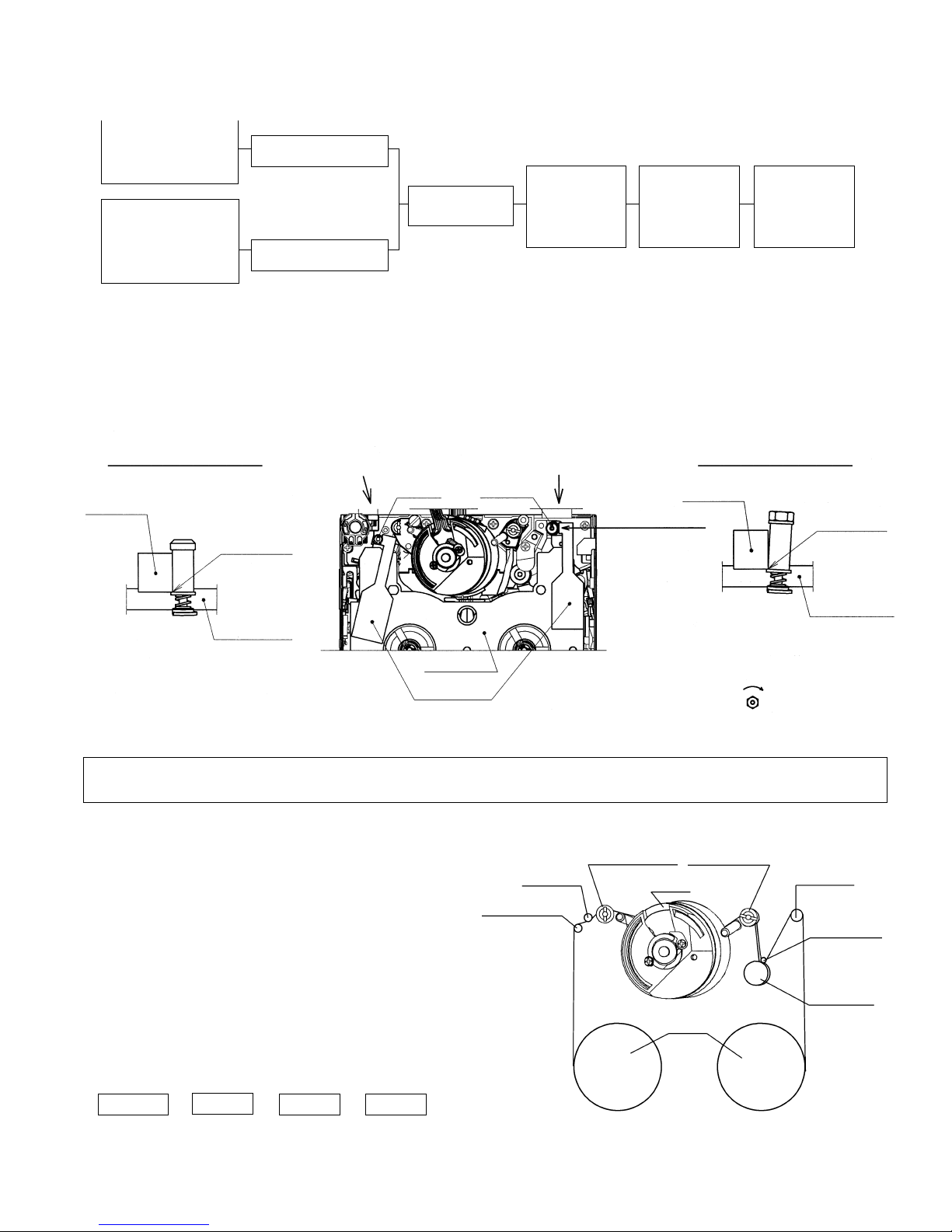
7-2. Adjustment of height of running system
· After replacement of the T pole, Tu guide and slide chassis, adjust the height of the T pole/Tu guide using the height adjustment jig.
· If wrinkles are found in the tape, turn the Tu guide to remove them.
(For further details, refer to "Coarse adjustment of running system".)
· After adjusting the T pole and Tu guide height, apply screw loctite at the tip of the shaft.
Readjustment of height
Presetting of height not
necessary
Installation of
cassette controller
Preparations for
adjustment of
Running system
Adjusting
procedure(8-3)
Coarse adjustment
of Running system
Adjusting
procedure(8-4)
Final adjustment
of Running system
Adjusting
procedure(8-5)
T pole Height setting Tu guide height setting
Height
adjustment jig
Lower edge
alignment
View B
Master plane
View B
T pole
Master plane
Height
adjustment jig
Tu guide
View A
Height
adjustment jig
Apply it in this direction.
View A
Align the top face of the lower flange of the Tu guide with
the bottom edge of the height adjustment jig.
After adjusting the height, turn the head clockwise 180
degrees.
Lower edge
alignment
Master plane
7-3. Preparations for adjustment of running system
Measuring instrument and Jig : Oscilloscope, Adjustment remote control, Height adjustment screwdriver, Alignment tapes (for
adjustment of running system and adjustment of SW point), Master plane, Height adjustment jig
<Method and description>
(1) Clean the surfaces that come in contact with the tape. (Clean
well the drum surface and the lower drum helical surface in
particular.)
(2) Install the cassette controller.
(3) Connect the oscilloscope to each TP of the joint circuit board.
(4) Turn ON the power of the AC adapter.
(5) Select TEST mode T-05 with the adjustment remote control.
(6) Play back the alignment tape for running system adjustment
and check that the tape is moving in the SP mode.
(7) While observing the PB envelope on the oscilloscope, adjust
the running system so that the envelope becomes flat in
states of [+1/4 shift] and [-1/4 shift].
(Each time the PB key is pressed, the shift amount changes
as shown below.)
+1/4 shift - Normal - -1/4 shift - Normal
S guide
Tension pole
Sup guide roller
Drum
Tu guide roller
Tu guide
Capstan shaft
Pinch roller
Reel
13
VL-Z400S-T/H-T
VL-Z500S-S/H-S/E-T/E-S
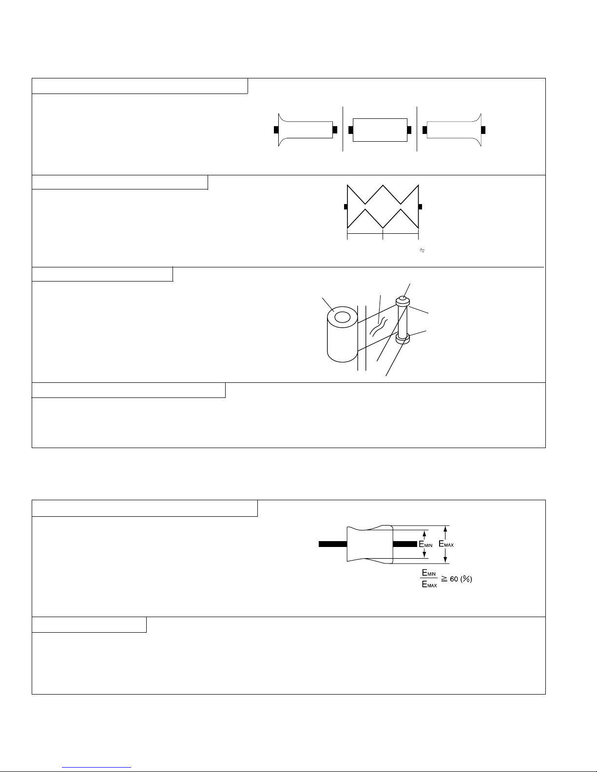
7-4. Coarse adjustment of running system
(Cassette controller installed)
1. Adjustment of height of Su and Tu guide rollers
<Method and description>
(1)Play back the alignment tape for running system
adjustment and make adjustment so that the inlet
and outlet sides of the envelope become flat.
(2)In states of [+1/4 shift] and [-1/4 shift], make
adjustment in the same manner as described in (1)
above.
2. Checking of V/SR envelope waveform
<Method and description>
(1) In the V/SR mode, check that the envelope waveform
is shaped uniformly.
(2) If the envelope waveform is not shaped uniformly,
fine-adjust the guide roller and Tu guide.
NG
±1/4 shift
A
Outlet side
Normal
B
Inlet side
Make adjustment so that A B.
NG
±1/4 shift
3. Checking for wrinkles in tape
<Method and description>
(1) In the PB mode and V/SR mode, check the tape for
distortion between the Tu guide and the pinch roller.
- If wrinkles are found, make adjustment within a
range of ±180 degrees.
Pinch roller
Wrinkle
Tu guide
Distortion
Distortion
- After making adjustment, apply loctite adhesive to
the tip of the shaft.
4. Checking of envelope waveform rise time
<Method and description>
(1) Check the envelope waveform rise time in switching from the V/SR mode to the PB mode. - 5 seconds or less
(2) Check the envelope waveform rise time in switching from the STOP mode to the PB mode. - 5 seconds or less
7-5. Final adjustment of running system
(Cassette controller installed)
1. Adjustment of height of Sup and Tu guide rollers
<Method and description>
(1) If the ratio of MIN to MAN of the envelope waveform is less
than 60%, adjust the height of the guide roller again. (See
Fig.1.)
(2) Perform unloading and then loading again, select the PB
mode and check that there are no significant changes in
the envelope waveform.
Fig.1
2. Adjustment of PB SWP
<Method and description>
(1) Play back the alignment tape for SW point adjustment.
(2) Using the adjustment remote control, make SWP automatic adjustment.
(3) Check that an OK is given as a result of self-judgment. In the case of a NG, adjust the GR height again.
* After replacement of the mechanism and drum, adjust the phase and equalizer using the adjustment remote control.
(Refer to "9. METHOD OF ADJUSTING THE ELECTRICAL CIRCUITS".)
14

VL-Z400S-T/H-T
VL-Z500S-S/H-S/E-T/E-S
8. ASSEMBLING OF MECHANISM SECTION AND PART REPLACEMENT
(DISASSEMBLING AND ASSEMBLING)
This section describes the method of assembling the mechanism section and the method of part replacement.
For how to remove the cabinet etc., refer to "3. DISASSEMBLY OF THE SET".
<Cautions>
1. Cut washers removed at the time of part replacement etc. should be replaced with new ones without fail.
2. When assembling the mechanism, take care to prevent screws, washers and foreign matter from getting into it. If such things
get into the mechanism, it will cause the mechanism to malfunction.
3. Be sure to use the specified cleaning liquid, oil, grease and loctite adhesive shown below. Failure to do so will cause the
mechanism to malfunction.
Oil: Cosmo Hydro HV22 (Cosmo Oil) Loctite adhesive: 1401B (Three Bond)
Grease: Molykote YM-103 (Dow Corning), Suncall CFD-409Z (Sankei Chemical Co., LTD.)
Cleaning liquid: Industrial ethyl alcohol
8-1. Mechanism mode
To operate the mechanism singly, apply 3 to 4V DC to the loading motor.
(Do not apply external voltage to the loading motor with the mechanism connected with the main circuit board. Doing so could cause a failure.)
(1) Ejection mode
This mode is used to take out a cassette. In this mode, the
ejection lever is shifted farthest in the direction shown by
Arrow A. (In this mode, the cassette controller assembly
cannot be locked.)
(2) Standby mode
This mode is used to set a cassette. In this mode, the slide
chassis is farthest away from the drum and the ejection lever
is turned (the cassette controller assembly can be locked).
(The tip of the ejection lever is hidden behind the main chassis
and the moving part of the down SW is visible.)
Ejection lever
Back view
Main chassis
EJECTION MODE
(3) L start mode
This mode is used for the Tu reel hub to take up the tape
of a cassette whose leader tape is visible. (In this
mode, the S main brake is located away from the S reel
table.)
Down SW
(moving part)
Ejection lever
Main chassis
STANDBY MODE
(4) Stop mode
This mode is used for stopping (camera mode:
RecLock). In this mode, the S and T pole bases are
pressed against the drum base and the S main brake
is engaged with the S reel table. However the pinch
roller and capstan shaft are separated.
S pole base
Drum base
T pole base
Capstan shaft
Back view
Pinch roller
S reel table
S main brake
L START MODE
S reel table
S main brake
STOP MODE
15
VL-Z400S-T/H-T
VL-Z500S-S/H-S/E-T/E-S
(5)PB (Record, Fast forward, Fast rewind, VSF and VSR)
mode
This mode is used for playback, recording, fast-forwarding,
fast -rewinding, VSF and VSR. In this mode, the pinch roller
is pressed against the capstan shaft and the S main brake
is located away from the S reel table.
Capstan shaft
S reel table
S main brake
PB (RECORD, FAST FORWARD,
FAST REWIND, VSF AND VSR) MODE
Pinch roller
8-2. Cassette controller assembly
<Procedure for removing the cassette controller> (The cassette controller can be installed and removed without removing the cover.)
(1) Apply 3 to 4V DC to the loading motor to establish the standby mode. When removing the cover from the cassette controller, remove
the tow screws (A). (See Fig.1.)
(2) Push the lock lever in the direction shown by the arrow and move up the cassette controller. (See Fig.2.)
(3) Remove the two screws (C) and remove the down guide (D) in the direction shown by the arrow (E). (See Fig.3 and Fig.4.)
(4) Shift the cassette controller in the direction shown by the arrow (F), remove the inner arm guide shaft L and the groove of the inner
arm R toward the inside of the mechanism, and turn the cassette controller. (See Fig.5 and Fig.6.)
(5) Turn the cassette controller in the direction shown by the arrow (H) and shift it in the direction shown by the arrow (I) to remove it
from the slide chassis. (See Fig.7.)
(A)
(B)
Fig.1 Fig.2
(C)
(C)
(D)Down guide
Fig.3
At this position, remove the inner arm guide
shaft L toward the inside of the mechanism.
Fig.5 Fig.6
(E)
(F) (F)
(E)
16
Fig.4
At this position, remove the groove of the inner arm
R toward the inside of the mechanism.
(H) (H)
VL-Z400S-T/H-T
VL-Z500S-S/H-S/E-T/E-S
(I)
Fig.7
(I)
Fig.8
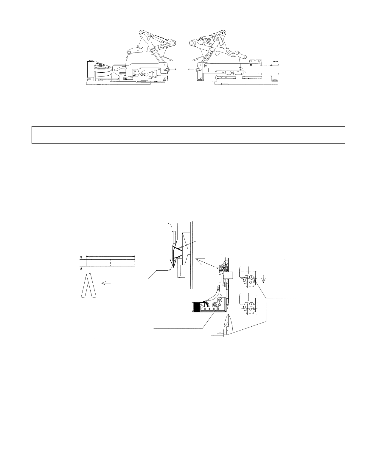
8-3. Method of operating on the circuit board with the cassette controller assembly removed
If this method is performed improperly, the tape may be damaged. Therefore do not use this method except in special cases
such as measuring the VSR torque. Be sure to follow the cautions shown in this manual.
(1) Apply 3 to 4V DC to the loading motor to establish the standby mode.
(2 Insert a sheet of thick paper folded in two as shown in Fig.9 into the position shown in Fig.10 to turn OFF the down SW.
(Pass the paper along the heavy line in the figure.)
Note) To go into the REC mode, press the pin of the recognition SW.
(3 Selecting the test mode (T-01) with the adjustment remote control without setting a tape will make it possible to operate
the mechanism with the mode keys.
(4) For ejecting, remove the paper inserted in step (2) above.
Pass the folded paper between
the slide chassis and the lock cam
to press the moving part of the
down SW.
34~36
5
Fold a sheet of paper
in two.
Fig.9
Recognition SW pin
Fig.10
Press
Moving part of
down SW
17
VL-Z400S-T/H-T
VL-Z500S-S/H-S/E-T/E-S
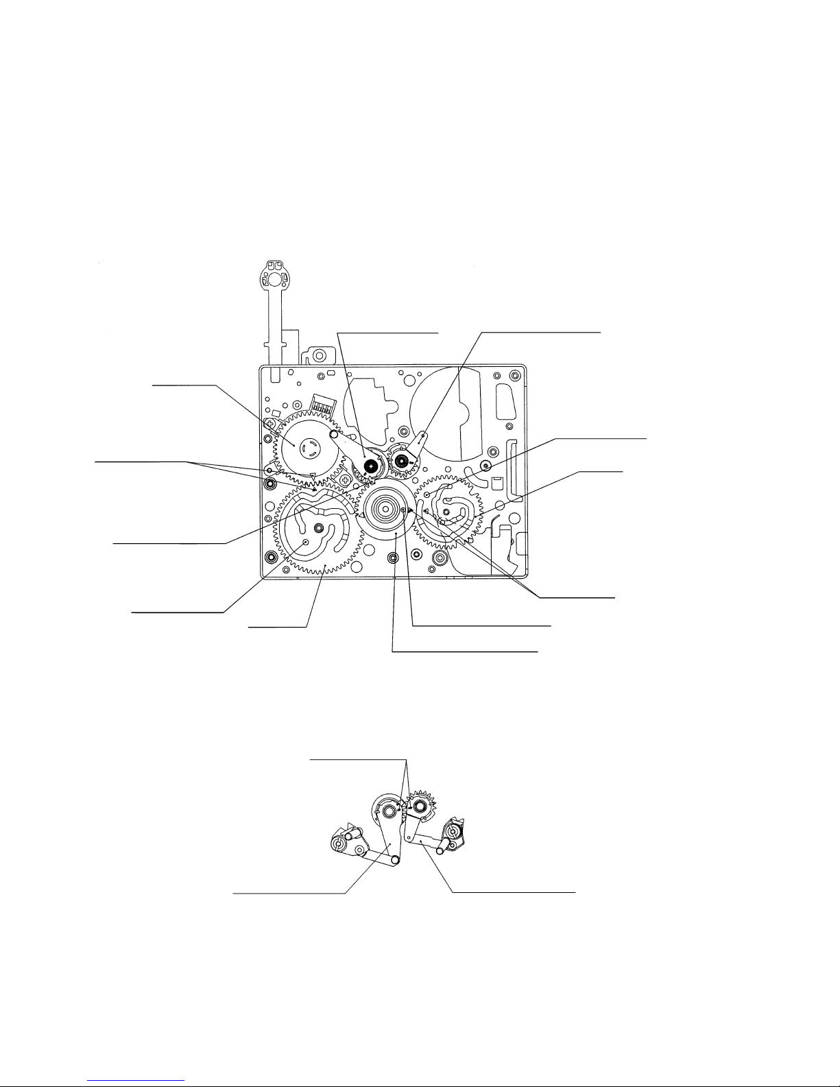
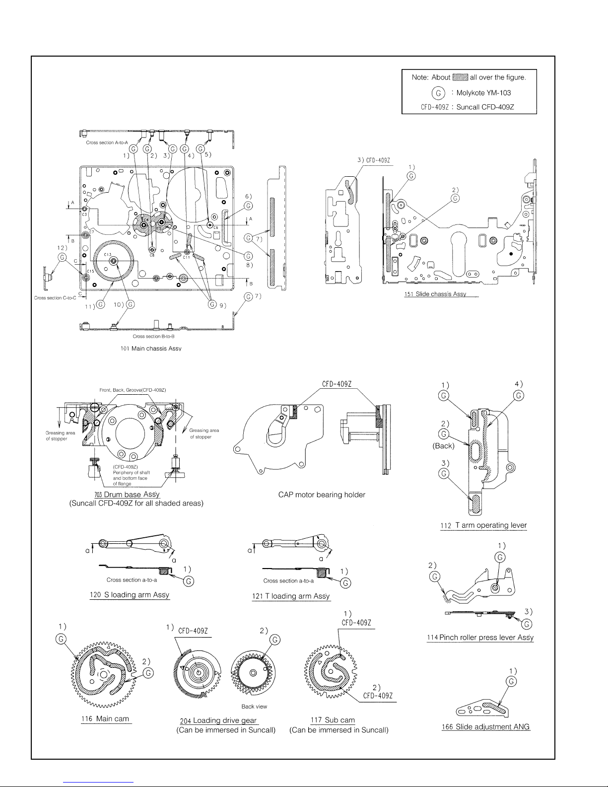
8-4. Phase-adjust
Phase-adjust the following parts.
(1) Mode SW
(2) Main cam
(3) Sub cam (The main cam and sub cam should be also phase-adjusted for the chassis.)
(4) S loading arm
(5) Tu loading arm
(6) Loading drive gear (main cam, sub cam, S loading gear)
Note) Check the marker position carefully before disassembling.
Note) When installing the loading drive gear, check that the main cam, sub cam, S loading gear are all phase-adjusted.
(5)Tu loading arm ass'y(4)S Loading arm ass'y
(1)Mode SW
Phase adjustment
Phase adjustment
mark
hole (for chassis)
(3)Sub cam
Phase adjustment
(gear section)
Phase adjustment
hole (for chassis)
(2)Main cam
Phase adjustment
mark
(4)S loading arm ass'y
Phase adjustment
mark
Phase adjustment hole
(for chassis)
(6)Loading gear drive gear
Fig.1
(5)Tu loading arm ass'y
Fig.2
18
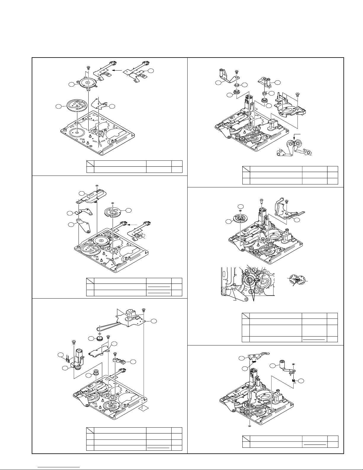
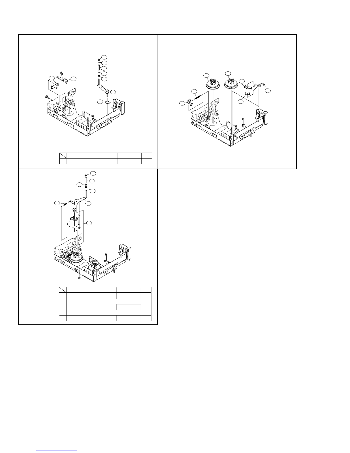
8-5. Assembling method
8-5-1. Method of assembling the main chassis assembly
Note) For reference, numbers are prefixed to parts names to show the sequence of assembly.
(For the greasing/oiling and cleaning locations, refer to the diagram of greasing/oiling locations.)
VL-Z400S-T/H-T
VL-Z500S-S/H-S/E-T/E-S
1.
2.
302
(1)Mode SW
304
(3)Main cam
(4)T arm operating lever
(3)S brake operating
lever
308
307
(2)SL drive lever
A
303
(2)LM/Mode FPC
305
(4)Ejection lever
Type
Tightening torque
A M1.4xL1.6(Special screw) 0.4mN·m2
H
309
B
306
(1)Sub cam
Q'ty
4.
5.
321
(4)S pole base loading
arm ass'y
322
(6)S Loading gear
324
(2)Loading drive
gear
E
(1)T pole base loading arm
(5)S press SPR
323
ass'y
320
319
(3)Tu loading
gear
Type
318
(2)Tu press SPR
D
(7)Drum base
sub ass'y
Phase adjustment
Tightening torque
D S Tight M1.4xL3.0 0.4mN·m3
E M1.4xL2.0
415
(t0.2 special screw)
G
F
325
(1)Guide rail
0.4mN·m1
Q'ty
In alignment with
chassis hole
BCWø1.2-ø3.0t-0.25 1
Type
Tightening torque
Q'ty
Phase adjustment (back)
HCWø0.7-ø1.8-t0.2 1
In alignment with
3.
C
316
(7)Relay pulley
314
(5)Center gear
B
(1)SLA support
310
C
(4)TLA support
Type
(3)DEW sensor
312
311
(2)L Motor ass'y
D
C
315
(7)Capstan motor
ass'y
313
(6)CAP FPC protection tape
Tightening torque
6.
Q'ty
chassis hole
(1)Pinch press
lever ass'y
(2)Pinch press SPR
C S Tight M1.4xL2.0 0.4mN·m5
D S Tight M1.4xL3.0 0.4mN·m1
BCWø1.2-ø3.0t-0.25 1
Phase adjustment (front)
F M1.4xL1.5
Type
(t0.2 special screw)
Tightening torque
0.4mN·m1
G M1.2xL4.6 0.4mN·m1
(t0.2 particularly special screw)
415 CWø1.2-ø3.0t-0.25(Lumirror) 1
326
327
H
329
(3)Pinch lever
ass'y
Type
H
328
(4)Pinch lever return SPR
Tightening torque
HCWø0.7-ø1.8-t0.2 2
Q'ty
Q'ty
19
VL-Z400S-T/H-T
VL-Z500S-S/H-S/E-T/E-S
8-5-2. Method of assembling the slide chassis assembly
1.
3.
(2)T-SPR adjustment
ANG
343
I
(19)T arm SPR
(8)Guide nut
349
(6)Tu guide flange
347
(7)Tu guide
Type
348
(6)Tu guide flange
347
(5)Guide adjustment SPR
346
(4)Tu guide arm
ass'y
345
344
Tightening torque
I
(1)Slide adjustment
ANG
342
(3)Tu guide arm SPR
I Precision type 2·M1.4xL1.0 0.4mN·m2
414
(23)TP Top Flange
413
412
357
C
(17)Tension arm ass'y
(22)T Post
411
(20)TP adjustment SPR
(21)TP bottom Flange
359
Q'ty
2.
(15)S main brake
355
(13)S reel table ass'y
(16)S brake SPR
356
(14)Tu reel table ass'y
353
354
(10)T brake gear
(11)T main brake
352
351
350
(9)VSR brake lever
(18)Tension band ass'y
358
H
H
Type
Tightening torque
Q'ty
C S Tight M1.4xL2.0 0.4mN·m1
(Tightening fully)
0.05mN·m
(Tightening temporarily)
HCWø0.7-ø1.8-t0.2 2
20
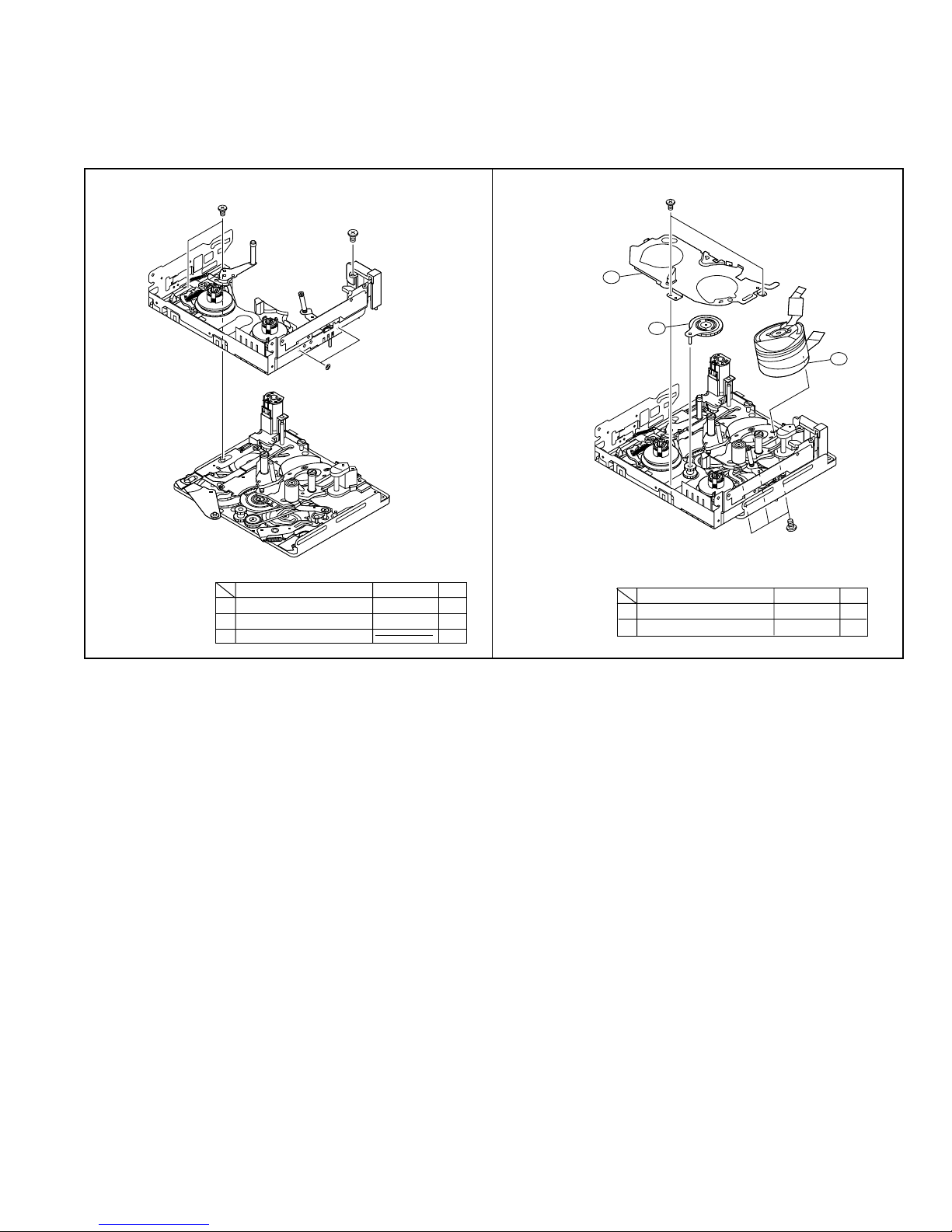
VL-Z400S-T/H-T
377
(22)Drum ass'y
371
(20)Swing arm ass'y
372
(21)Reel cover ass'y
D
I
VL-Z500S-S/H-S/E-T/E-S
8-5-3. Method of combining the main chassis assembly and the slide chassis assembly
(1) Position the assemblies as shown in the figure below (the pole base is slightly protruded).
(2) Insert the operation pins (tension arm, Tu guide arm) of the slide chassis assembly into the locations of the main chassis assembly
shown in the figure below, fit the SL drive lever pin of the main chassis assembly into the groove of the slide chassis (the groove
of the slide adjustment ANG), and then fix with the two screws.
1.
C
D
J
Type
C S Tight M1.4xL2.0 0.4mN·m2
D S Tight M1.4xL3.0 0.4mN·m1
JWø2.1-ø4-t0.25 2
Tightening torque
Q'ty
2.
Type
D S Tight M1.4xL3.0 0.4mN·m1
I Precision type 2·M1.4xL1.0 0.4mN·m2
Tightening torque
Q'ty
21
VL-Z400S-T/H-T
VL-Z500S-S/H-S/E-T/E-S
8-5-4. Diagram of greasing/oiling locations
22
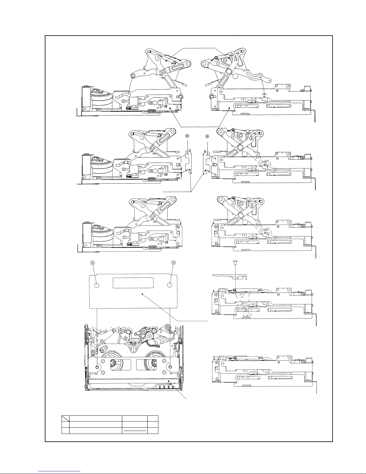
8-6. Method of installing the cassette controller
(2)Completed cassette
controller
1
VL-Z400S-T/H-T
VL-Z500S-S/H-S/E-T/E-S
2
3
Left side view Right side view
Left side view
B-1 B-2
Left side view Right side view
(3)Down guide
(1)Main slide
ass'y
A-1
A-2
Right side view
B-1,2
4
Mechanism viewed from above
A Ml1.4xL2.0(Precision type 2) 0.4mN·m2
Type
B M1.7x2.5(Precision type 2) 2
Tightening torque
Q'ty
(4)Cassette cover
Right side view
5
Right side view
C: Move down the cassette controller by pushing this
portion. When the cassette controller is locked,
attach the cassette cover.
23
VL-Z400S-T/H-T
VL-Z500S-S/H-S/E-T/E-S
8-7. Method of taking out the cassette with the mechanism operating singly
(1) Apply 3 to 4V DC to the loading motor for slight unloading.
(2) If the tape is slack, turn the rotor (mechanism backside) of the capstan motor by hand to take up the slack in the tape.
(3) Repeat steps (1) and (2) above. When the pole base is completely unloaded, check that the tape is not slack.
(4) Then apply 3 to 4V DC to the loading motor again. The cassette controller will move up.
(5) Take out the cassette.
Note) When applying 3 to 4V DC to the loading motor for unloading, do so as shown in Fig.1.
Direction of rotation of the rotor
of the capstan motor (from
mechanism backside)
Loading motor
+ pole
— pole
Fig.1
24

VL-Z400S-T/H-T
VL-Z500S-S/H-S/E-T/E-S
9. METHOD OF ADJUSTING THE ELECTRIC CIRCUIT
-Before making adjustment-
· It seems that, in most cases, this adjusting method is used when it becomes necessary to adjust the electric circuit as a result of
replacement of worn mechanism parts or the video head. When adjusting the electric circuit, check that the mechanism operates
properly (the mechanism is adjusted completely). If a failure occurs in the electric circuit, be sure to locate the fault using a
measuring instrument and then perform repairing, replacement and adjustment, as described in this adjusting method.
Avoid performing undue adjustments etc. without using proper measuring instruments.
· The electric circuit components in the circuit board unit of this product are densely-packed into packages. Most of them are surfacemounted for downsizing.
When replacing components in servicing the product, perform replacement work swiftly with a soldering iron.
In general, surface-mounted components are inferior in heat resistance to large-sized discrete components used in TV sets,
stationary decks, etc. Heating the electrode of a surface-mounted component with a soldering iron for a long time needlessly will
therefore lead to a failure. Take great care not to do so.
Take special care in this respect when replacing chip multilayer capacitors in particular.
We recommend you to use a ceramic soldering iron (Tip temperature: 250°C, Contact time: 5 seconds or less).
9-1. Adjustment of liquid crystal video section
List of measuring jigs
· Color monitor TV
· Digital voltmeter
· DC power source
· Audio generator
(CR oscillator)
· Frequency counter
· AC adapter
· Stereo AV output cable (supplied)
· Adjustment remote control
(RRMCG0033TASA)
· Signal generator
(NTSC pattern generator LCG-401/
401YC: Manufactured by Leader)
· Oscilloscope
· Vector scope
· Tape for recording
· DC cable (supplied with AC adapter)
· Extension wire of video section
· Alignment tape
90ADDVC-TAPE (color bar)
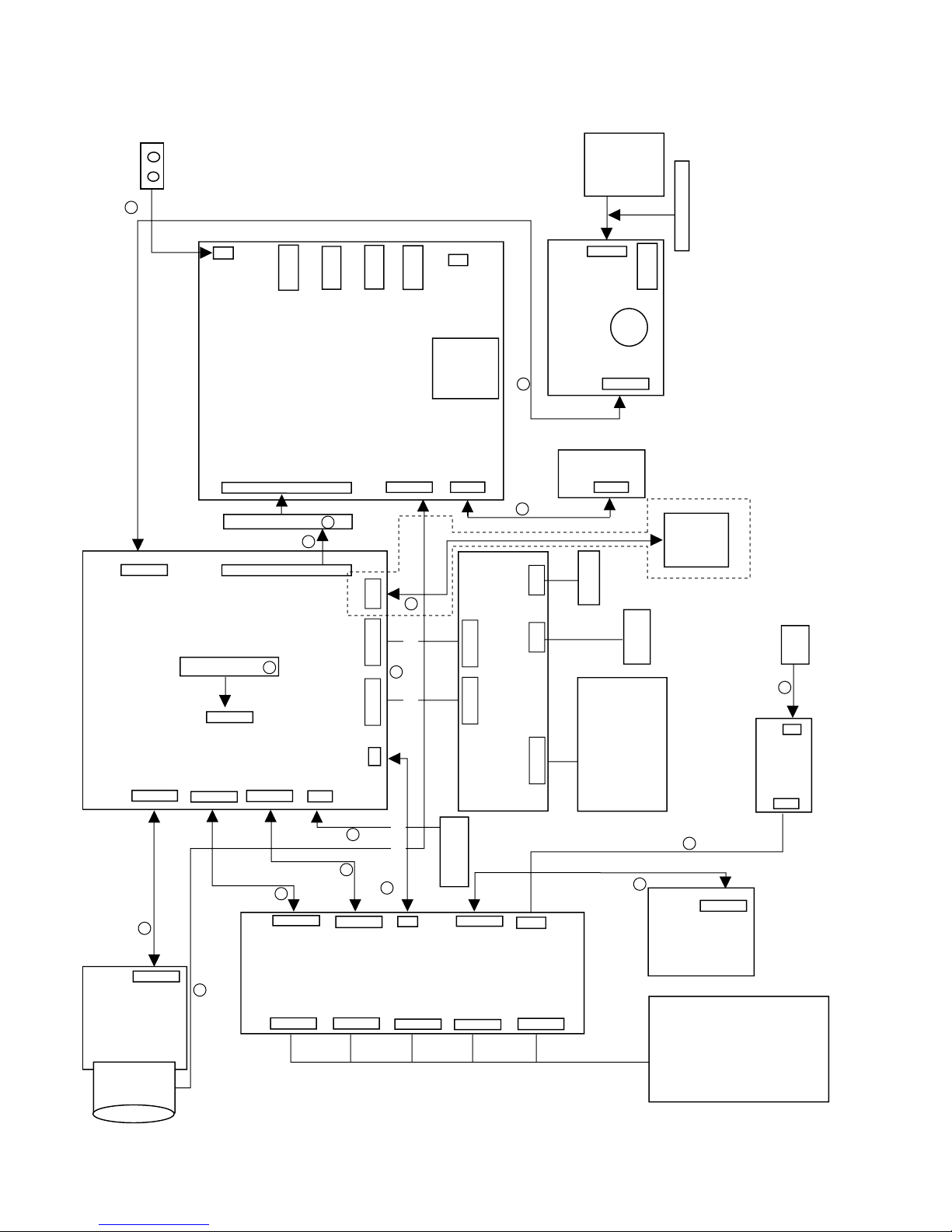
VL-Z400S-T/H-T/Z500S-S/H-S/E-T/E-S Specifications of service jigs
No. Connection section Connector REF. No.
No. of pins
New/
Cont.
Parts cord
1 H/A PWB — MAIN PWB1 SC307—SC3302 33P C QPWBHB737WJZZ AN
2 H/A PWB — MAIN PWB2 SC308—SC3301 33P C QPWBHB737WJZZ AN
3 V/F — USB PWB SC5801 18P QPWBHC376WJZZ Product used AF
4 MAIN — USB PWB SC8800—SC5800 27P-25P QPWBHB742WJZZ Product FPC used AE
5 MAIN — RUNTA005WJZZ SC1201 80P C QCNW-1373TAZZ BQ
6
RUNTZA005WJZZ
— SUB P2901 80P C RUNTZA005WJZZ AX
8 Menu key — SUB SC2002—SC501 9P-15P QPWBHB772WJZZ Product FPC used AE
9 H/A PWB — MAIN PWB P301—P3301 5P QCNW-B171WJZZ Product wire used AF
10
TP jig for envelope checking
P3303 30B-B C RUNTZA004WJZZ AW
11 Power supply SC310—SC2101 12P QCNW-B167WJZZ Product FFC used AC
12 ZOOM SC311—SC2201 10P C QPWBHB746WJZZ AE
13 CCD PWB — MAIN SC1001—SC1202 33P QPWBHB738WJZZ Product FPC used AD
14 Lens unit — SUB SC551 25P CLNS-A005LM58 Product unit used BN
15 MIC — SUB P3602 4P RMiCCA009WJZZ Product unit used AM
16 INNER LED — MAIN INNER LED—SC1204 12P QPWBHC378WJZZ Product FFC used AE
(VL-Z500 only)
17 MECHA TURN — MAIN P1201 2P DUNTKC372PM00 Product unit used AG
19 SPEAKER — ZOOM P2201 2P VSP0020P-B3WN Product unit used AL
20 LCD UNIT — MAIN SC1800/SC1801 18Px2 QPWBHB736WJZZ Product FPC used AR
Price
code
25
VL-Z400S-T/H-T
Lens
CCD PWB
QPWBHB738WJZZ
HEAD AMP PWB
SC303
SC307
SC301 SC308
SC304
SC310
SC306
SC311
SC305
P301
10
10
7
27
QCNW-B171WJZZ
LCD
LAMP
INNER
LED
ZOOM PWB
P2201
SC2201
SPEAKER
SC2002
MENU
SC5800
SC5801
USB
BAT
P900
SC1501
SD
SC501
J600
J7401
J1401
J2900
P3602
SUB PWB
P2901
SC1201
W8089
P3303
SC3302
SC3301
P1201
P3301
SC1801
SC1800
SC1204
MAIN PWB
SC8800
VF_IF
RMiCCA009WJZZ
POWER SW
SC802
LCD PWB
SC801 SC800
SC803
SC9800
18 18
15
25
3
18
25
9
80
4
SC551
80
12
1818
30
27
SC1202
33
33
33
33
33
12
2
5
MECHA TURN
24
6
10
SC2101
12
10
10
2
21
*1
*2
QPWBHC378WJZZ
QCNW-1373TAZZ
RUNTZA005WJZZ
RUNTZA004WJZZ
SC1001
5
AV
DV
HP
DC
QPWBHB742WJZZ
QPWBHB772WJZZ
QPWBHB737WJZZ
QCNW-B167WJZZ
QPWBHB746WJZZ
LI
13
14
9
17
20
16
19
4
8
15
1
2
10
5
6
11
12
QPWBHB736WJZZ
Mechanism
*1: Under surface contact
*2: Top surface contact
Caution: Don't make a mistake in putting in SC3301 and SC3302.
HOLE SENSOR
VF
QPWBHC376WJZZ
QPWBHB737WJZZ
(VL-Z500 only)
VL-Z500S-S/H-S/E-T/E-S
VL-Z400S-T/H-T/Z500S-S/H-S/E-T/E-S Service jig configuration
26
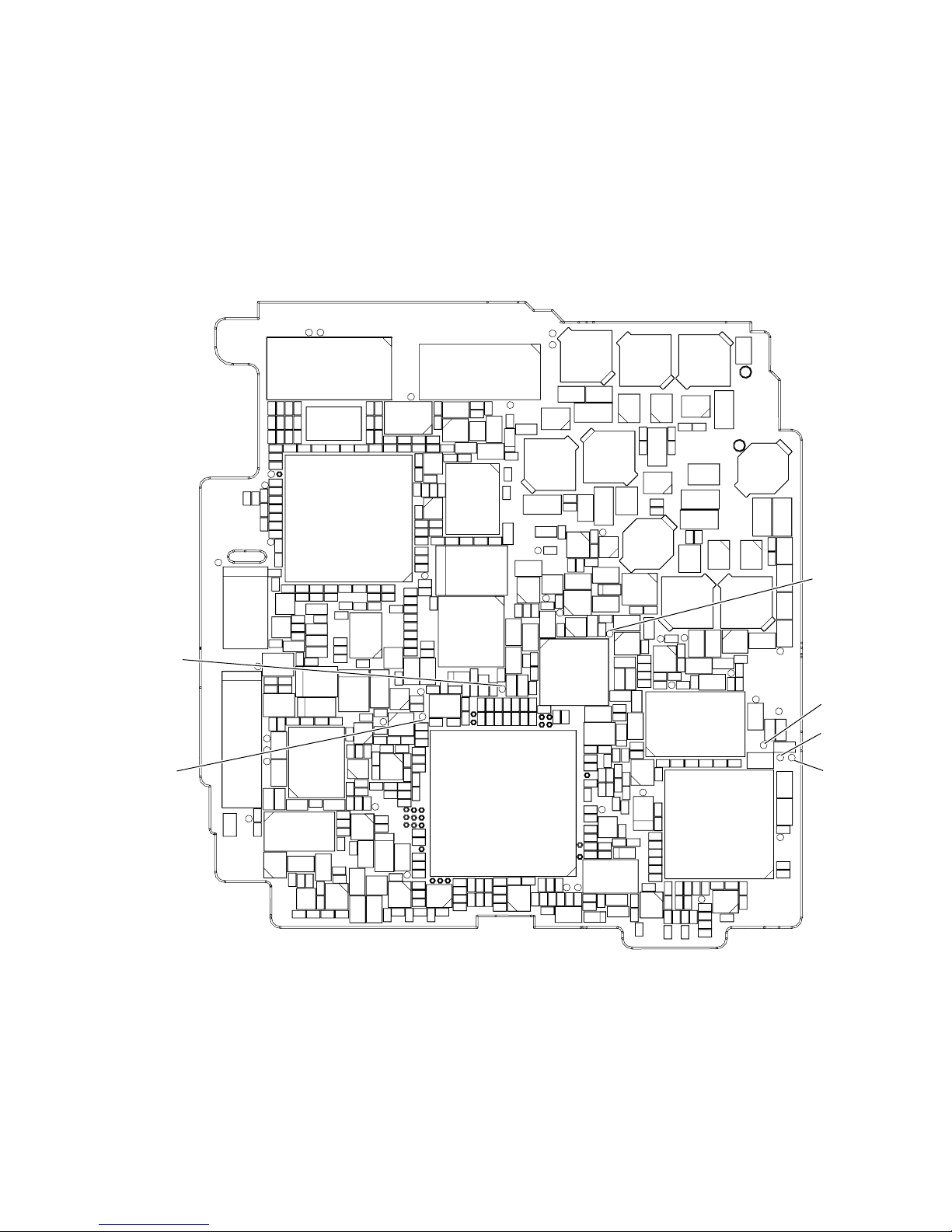
[TEST POINT]
VL-Z400S-T/H-T
VL-Z500S-S/H-S/E-T/E-S
(Wiring board diagram: Main Side A)
TL7824(VF_G_OUT)
VF_DAC full scale
TL6807(G_OUT)
DAC full scale
TL1207
TL3302TL3304
SC3301
TL3310
C730
R1828
C1411
C1419
R1421
C1436
R1414
R1462
R1403
L4404
C4404
R1820
Q1403
TL1450
Q1434
C725 R752 C723
R757
C733
R725
R6839
R1424
C4424
R1404
L4406 IC1800
Q4483
R1422
TL1452
R1423
R1439
R1438
C4483
R6836R6835
R751 R753 C726
R755
R720
C1412
R6840
C728
R750
C6827
C220
R246
C4481
R1827
R4489
R4482
Q1404
Q6800
R4481
Q1802
R6833
C4422
TL4424
IC706
R754
C737
R1801
C1801
R1800
C1804
C1803
C1802
R1804
R1803
C6801
R6832
C219
R219
TL206
TL208
C4406
TL4400
Q4481 Q1402
C6829C6828
TL207
TL210
TL212
R749
C722
C4401
TL1451
R1419
R1402
TL6807
C4418
R4415
C4417
R4495
C4426
TL4425
C4428
R4494
C4423
R4485
C4485
R4486
R4488
C4482
R711
R782
R730
R708
R710
R706
TL8803
R6808
R6807
R6837
C4425R4473
TL205
TL209
TL211
X702
R756 R760 R764
R761 R765 R766
R745 R722 R762
R717 R728 C713
C711
C709
R743
R714
TL701
TL3303
R744
TL3311
C731
R709
R702
C703
R742
R712 C716
R723
R705
R724
R732
TL1206
C736 C735
R707
C708
R715
Q704
P3301
R718
R771
R772
R747
C704
L1803
TL1812
C1815
R1816
C1813
C1812
L1802
R1406
R1814
R1813 Q705
TL1808
SC1800
TL1809
TL1810
L1404 C1402
C1408
C1439
C1441
TL1431
2
C1438R1442
Q1431
IC1431
L1431
R1437
R1435
C719
R746
R748
C720
IC701
C710
R735
R759
R736
R729
R763
R738
R737
R1822
R1821
C1811
R1823
R1807
C1810
C1809
R1826
R1825
C1808
R1824
C1814
R1817
C1406
C1407
C1416
C1418
R1405
R1413
R1461
Q1405
IC1401
C1410
C1409
R1401C1417
C1437
R1440
R1441
C1440
C1432
C1431
R1431
C1435
R1436
Q1432
Q1433
C1434R1432
R1434
R1433
C1433
R731
R740
C717
R734 R719 R741
R4402
R4401
R768
R716
C729
R721
R6805
C4421
TL4429
C732
C727
C715
C4402
TL4428
Q4482
R4409
C707
Q701 Q702
C705
R4408
C724 R1932
R779
R713
L6800
TL4426
R704
R726
C6804
C6800
R6800
C3321
Q703
D6800
C4433
C4409
C4437
R4487
SC3302
R3321
C3320
C712
R703
R727
X701
C4420
TL7805
TL7804
R4493C4419
C4410 C4411
Q3320
L701
IC704
C714
IC703
C7802
R7827R7802
R6820R6801
IC4401
R4474R4404
R3320
R701
C4412R4405
C706
TL7824
R7826
R6819R6802
C4431
R4436
R4437
C4436
R6818R6803
TL913
R7803
R739
R4407
C702
C734
C701
C7804C6805
D701 C3722
C7803
C8805 L8801
R7804R6804
R932
C1911
R1925
R4406
Q4432
C7801
R4472R7828
TL920
Q1913
R1928
C8800
L8800
TL7802
R4471R6809 R7801
TL4470
C991
C1940
TL903
R8802R8801
R6810
R4475 R1927
TL923
TL922
L923
C1960
Q1912
R1926
TL7801
TL204
R4477
R4476
R4435
Q911
TL904
C8804
C4414
C974
C992
R951
R1948
IC8800
C210
R4470
TL4439
C4413 R1924
C4430
C4432 R8800
C4435
R1944
C978
D960
Q8800
TL201
TL202
TL4438
C204
L917
R1947
TL203
R4456
C4429 Q1907
R4454
R1900
C7810
C211
C208
C207
C205
R4414
C4462
R4462
R4461
C4451
C956
C975
C4442
R201
D4452
C973
TL916
R1946R1945
C8801
L7810
R7811
TL4440
C4463
R4451
C962
C929
R8804
L911
C990
D916
TL8801
R8805
R7820R7832
X4451
C4454
Q1900
FB4402
Q4461 R7835
L4451
C4461
R8866
R4403
R7821R7833
C4465
C8806
Q8801
C8807
C8809
C7829C7828
R7838 C7812
D4451
D7810
R4463
R7834
R7837C7827
R7839
R4466
Q907
Q910
R8807
C8808
C7821
R7836
Q905
R8803
C8810
R8867
R8868
C8813
C4403
TL3707
R4464R4453
L916
R4460
R3725
R988 C971
L931
R8806
R8809
Q7800
FL3702
C954
R983
C8802
R3701
R3713
C3723
R3711
C3720
R8841
Q904
TL907
R8814
R8827
C3704
IC4461
C972
R3727
R3706R3707
Q906
C8803
Q8802
R8828
TL8802
R987 C970
TL911
C3710
R3705
R3726R3703
R3723
C3716 R8842
Q908
C980
R990
C955
C960
Q909 C953
L907
C939
R8808R8817
FB3701
IC3702
R3717
R3712 L908
TL3703
C3717
C3719C3713
R3724C3721
R3729
R3721
R3738
C3707
R3704 C3718
L918
L915
R982
C938
C3708
C3705
C3712
IC3701
R3709
C3724
C1901
Q3701
FB3719
Q903
C981
TL921
R3710
Q1901
C3709
TL901
C3727
C3729
TL902
L901
C3728C3725
C982
R3718R3739
TL908
Q900
TL8806
C3702
L900
C934
L3702
C931
C930
C932 R970
TL8801(VF_COM)
VF_COM
L903 C933 L902 C936
TL910
C8824
C3703
C3706
R3740
C8823
TL8805
C3701 L3701
TL8806(VF_VB)
VF_WB
TL8804(VF_VG)
VF_WB
TL8805(VF_VR)
VF_WB
TL8809
C8825
TL8804
TL3702
27
VL-Z400S-T/H-T
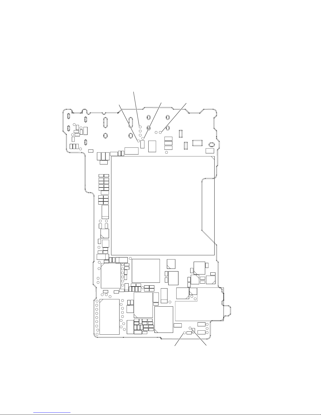
VL-Z500S-S/H-S/E-T/E-S
(Wiring board diagram: Sub Side A)
TL1470
Checking of EE level
Checking of f characteristics
TL1472
Checking of EE level
Checking of f characteristics
TL601
FB600
TL600
C602
VA603
VA602
TL602
C601
VA600
VA601
C600
R603
TL603
R604 C2905
R7429
R7428
R7427
R2915
R2914
C2906
R7426
TL1474
PCO_D/A-Y ADJ
TL1473TL1470
TL1471
TL1475
TL1472
R2901
TL1475
PCO_D/A-C ADJ
TL1474
TL1476
CP3
CP2
L2901
CP1
TL1477
1
TL551
TL553
TL557
TL559
TL561
TL563
TL567
TL571
C1501 R1501
C1503 R1502
C1502 C1508
C1504 R1503
C2904 C1509
C1505 R1504
C1506 R1505
C1507 R1506
TL1501
R1507
R1510
TL512
R1513 R1512
TL510
TL508
TL506
TL501
TL568
C1510
Q1502
R1511
D3601
R506
TL556
C1513
TL1502
R1509
Q1501
C523
C521
SC501
TL503
TL555
SC551
SC1501
C525
TL3603
D3600
TL511
VA501
TL509
C522
C524
TL507
TL505
TL502
TL504
R3635
R3602
TL552
TL554
TL558
TL560
TL562
TL564
TL569
TL566
TL570
VA502
D551
R582
R2523 R2530
R2520
R2527
R2526
R578
Q552
C2517 C2515 R2515
R2512 R2533 R2516
C2514
R2511
C2516
Q2903
TL565
R2525 R2531
R2528
C2520 C2521
IC2502
R581
R2510
C2519
R2514 C2518
R2509 R2513
R2508
R2931
C2902
R2919
R2911
D2904
TL3600
IC2901
Q2906
R2913
R2906
R2918
Q2902
R2905
Q2901
R2930
Q2905
D2902
TL903
TL904
R2917
R2904
Q2904
R2903
P900
TL902
C2903
C2910
TL3602
TL3601
R2916
TL901
R2910
TL900
C2901
TL3601(INT MIC L)
Checking of EE level
Checking of f characteristics
28
TL3602(INT MIC R)
Checking of EE level
Checking of f characteristics
VL-Z400S-T/H-T
VL-Z500S-S/H-S/E-T/E-S
[Execution of adjustment]
Adjustment of servo and system controller
1. System code setting
It is necessary to set the following data items after replacing IC705 (E2PROM).
<Adjusting method>
Select the VCR adjustment mode and set the data value at each address.
Code Specifications Destination Specifications Menu setting Software switching Calendar
Address 01 09 02 0A 03 0B 04 0C 05 0D 07 0F
Z400S(ST) 89 76 0A F5 D6 29 00 FF 00 FF 04 FB
Z400H(HT) 89 76 0D F2 DE 21 00 FF 00 FF 04 FB
Z500S(SS/AS) 99 66 0A F5 54 AB 00 FF 00 FF 04 FB
Z500S(RS) 99 66 2A D5 54 AB 00 FF 00 FF 04 FB
Z500E(ES/WS/ET/WT/XT) 99 66 0B F4 5C A3 00 FF 00 FF 04 FB
Z500H(HS) 99 66 0D F2 5C A3 00 FF 00 FF 04 FB
Code 1394/exif model name
Address 1A1 1A2 1A3 1A4 1A5 1A6 1A7 1A8 1A9 1BD 1BE 1BF
Z400S(ST) 56 4C 2D 5A 34 30 30 53 00 00 00 00
Z400H(HT) 56 4C 2D 5A 34 30 30 48 00 00 00 00
Z500S(SS/AS) 56 4C 2D 5A 35 30 30 53 00 00 00 00
Z500S(RS) 56 4C 2D 5A 35 30 30 53 00 00 00 00
Z500E(ES/WS/ET/WT/XT) 56 4C 2D 5A 35 30 30 45 00 00 00 00
Z500H(HS) 56 4C 2D 5A 35 30 30 48 00 00 00 00
• Automatic adjustment
Mode VCR ADJ mode
Adjusting 1) Using command 12, select the VCR adjustment mode.
2
method 2) Using command 20, enable writing to the E
PROM.
3) Using command 22, set the above-shown system codes according to the model.
4) Using the command, inhibit writing to the E
2
PROM.
5) Using the command, exit the VCR adjustment mode.
Examples • Replacement of E2PROM (IC705)
• Manual adjustment
Mode VCR ADJ mode
Adjusting 1) Set the CAM/OFF/VCR selector switch to VCR.
method 2) Press "CONTINUE" → "VCR adjustment" on the remote control to enter the VCR ADJ mode.
(At this time, "VCR ADJ" is displayed in the lower left part.)
Enter the specified value at each address.
· Shown below is the procedure for setting.
3) Select an address by increasing or decreasing the flashing numeric value with the FF or REW key
and press the PB key to confirm it.
4) Set the flashing numeric value to the specified value by increasing or decreasing it with the FF or
REW key and press the PB key to confirm it.
5) Press the STOP key to make it possible to select an address.
6) Repeat steps (3), (4) and (5) above until all the data items are set. Then press "CONTINUE" to exit
the VCR ADJ mode.
7) Set the CAM/OFF/VCR selector switch to OFF.
Examples ·Replacement of E
2
PROM (IC705)
2. Adjustment of HSWP
Mode VCR ADJ mode
Adjusting 1) Select the video mode and play back the alignment tape.
method 2) Press "CONTINUE" → "HSWP ADJ" keys on the remote control.
→
HSWP adjustment execution (When the adjustment is completed, "GOOD" is displayed on the LCD and
ejecting is performed automatically.)
If adjustment cannot be made, "NG" is displayed on the LCD.
Examples · Replacement of mechanism · Replacement of E2PROM
29
VL-Z400S-T/H-T
;
;
;
;
;
;
;
;
;;;;;;
y
y
y
y
y
y
y
y
yyyyyy
VL-Z500S-S/H-S/E-T/E-S
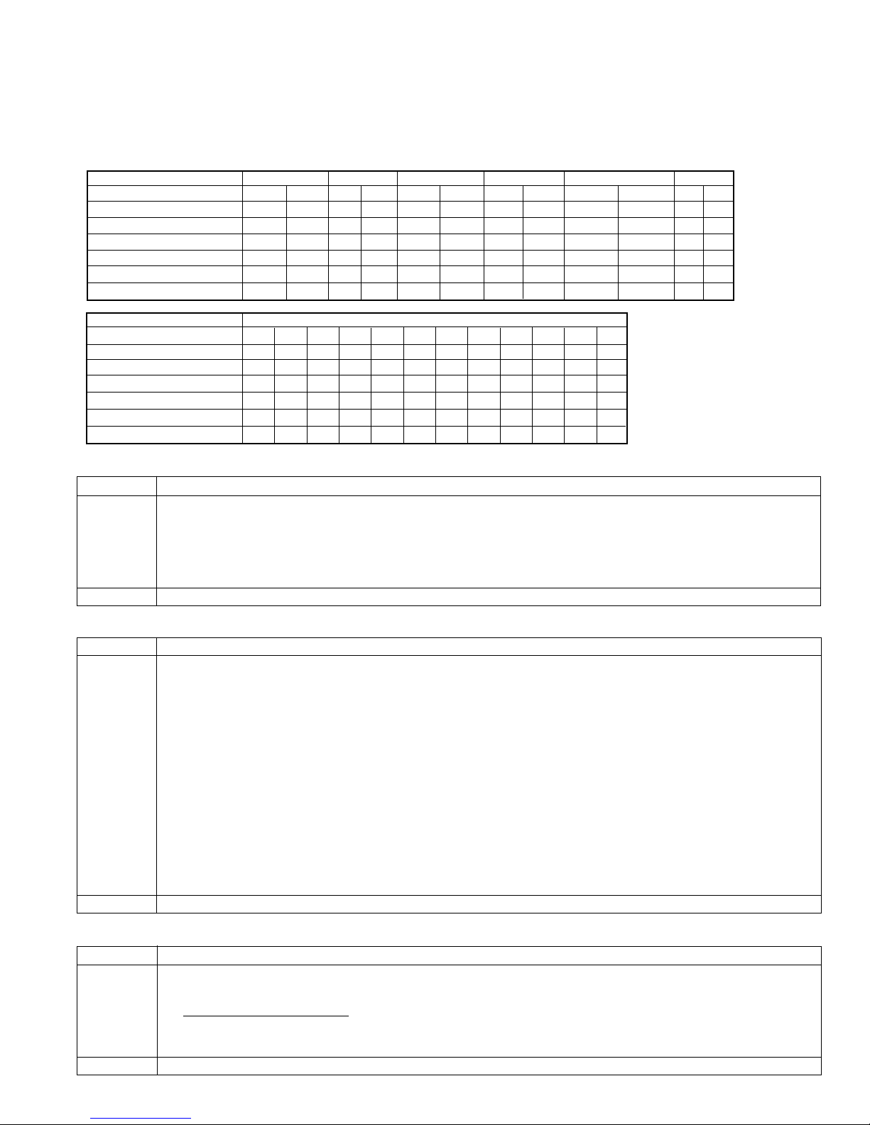
3. Adjustment of shutdown
Mode VCR ADJ mode
Adjusting 1) Set a recordable tape and select the camera mode.
method 2) Press "CONTINUE" → "TEST SEL" on the adjustment remote control to enter the TEST mode (T-01 flashing).
3) Select T-03 with the FF and REW keys and press "PB" key.
4) Adjust the power supply voltage so that TL904(+) becomes 6.00V ± 50mV as viewed from TL900(-).
5) Press the "Display change" button on the main unit. Turn OFF the power.
Examples · Replacement of microcomputer (IC701), Regulator (IC704) and E2PROM (IC705)
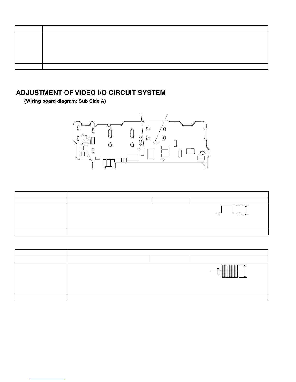
ADJUSTMENT OF VIDEO I/O CIRCUIT SYSTEM
(Wiring board diagram: Sub Side A)
TL1475
PCO D/A-C ADJ
TL601
FB600
TL600
C602
VA603
VA602
TL602
C601
VA600
VA601
C600
R603
TL603
R604 C2905
R7429
R2915
R2914
C2906
R7428
R7426
TL1473TL1470
TL1471
TL1475
TL1472
R2901
TL1474
L2901
TL1474
PCO D/A-Y ADJ
TL1476
CP3
CP2
CP1
TL1477
1
1. PCO D/A-Y adjustment
Measurement point TL1474 (connected to oscilloscope)
Address VCR ADJ 566 Mode EE mode
Procedure 1) Connect the AVS cable and then connect it to the monitor (TO).
2) Call the adjustment mode (V-ADJ).
3) Set the address to "566", and call the date. (100% white signal is output.)
4) Vary the date with the FF and REW keys to set the signal appearing at TL1474 to 1.0Vp-p ± 0.05Vp-p.
Examples • During IC705 replacement. • During IC4401 replacement. • During IC1401 replacement.
2. PCO D/A-C adjustment
Test point TL1475
Address VCR ADJ 567 Mode EE mode
Procedure 1) Connect the AVS cable and then connect it to the monitor (TO).
2) Call the adjustment mode (V-ADJ).
3) Set the address to "567", and call the data.
4) Vary the data with the FF and REW keys to set the signal appearing at TL1475 to 0.64Vp-p ±
0.05Vp-p.
Examples • During IC705 replacement. • During IC4401 replacement. • During IC1401 replacement.
;;;;
yyyy
;;;;
yyyy
;;;;
yyyy
;;;;
yyyy
1.0 ± 0.05
0.64±0.05
30
 Loading...