

Page 1
SERVICE MANUAL
VL-WD255U
SERVICE MANUAL
S41R8VL-WD255
LIQUID CRYSTAL DIGITAL CAMCORDER NTSC
LIQUID CRYSTAL DIGITAL CAMCORDER
In this Service Manual, only the differences from VL-WD250U/WD450U
(SY0N4VL-WD250) are described.
Therefore, for the parts which are not described in this Service Manual, refer
to the Service Manual for VL-WD250U/WD450U (SY0N4VL-WD250).
NTSC
MODEL VL-WD255U
2. SPECIFICATIONS.............................................................................................................................. 2
3. PART NAMES .................................................................................................................................... 3
10.ADJUSTING THE ELECTRICAL CIRCUITS...................................................................................... 3
14.SCHEMATIC DIAGRAMS .................................................................................................................. 4
15.SEMICONDUCTOR LEAD IDENTIFICATION ................................................................................. 18
16.PRINTED WIRING BOARD ASSEMBLIES...................................................................................... 19
17.REPLACEMENT PARTS LIST ......................................................................................................... 21
18.PACKING OF THE SET ................................................................................................................... 26
MODEL
In the interests of user-safety (Required by safety regulations in some countries) the set should be restored to its
original condition and only parts identical to those specified
be used.
CONTENTS
VL-WD255U
Page
SHARP CORPORATION
This document has been published to be used for
after sales service only.
The contents are subject to change without notice.
1
Page 2

VL-WD255U
2. SPECIFICATIONS
Recording/Playback Time: 90 minutes (DVM60, LP mode)
Lens Filter Diameter: 37 mm
Color Temperature Compensation: Auto white balance with white balance lock
Minimum Illumination: 1 lux (9 lux measured by EIA standard)(with gain-up, F1.6)
Still Image Compression
System/Recording Format: JPEG base line conformance/JPEG (Exif2.1)
Still Image Recording Medium: 3.3V type SmartMediaTM card (SSFDC)
Power Requirement: DC 7.4 V
Power Consumption: 4.0 W (during camera recording using the viewfinder in Full Auto mode with zoom
Operating Temperature: 32°F to 104°F (0°C to +40°C)
Operating Humidity: 30% to 80%
Storage Temperature: –4°F to 140°F (–20°C to +60°C)
Dimensions (approx.): 3 11/16" (W) × 4 21/32" (H) × 7 11/32" (D)
Signal System: NTSC standard
Recording System: 2 rotary heads, helical scanning system
Cassette: Digital VCR Mini DV video cassette
Tape Speed: SP mode: 18.812 mm/second
LP mode: 12.555 mm/second
Pickup Device:1/4" (6.4 mm, effective size: 4.5 mm) CCD image sensor
(with approx. 460,000 pixels including optical black)
Lens: 26 × optical/780 × digital power zoom lens (F1.6, f=3.5-91.0 mm), full-range auto
focus
Viewfinder: Electronic LCD color viewfinder
Monitor: 2.5" (6.3 cm) full-color LCD screen (TFT active matrix)
Microphone: Electret stereo microphone
motor off)
4.8 W (during camera recording using the LCD monitor in Full Auto mode with
zoom motor off and backlight in normal mode)
[93.7 mm (W) × 118 mm (H) × 186.5 mm (D)]
Weight (approx.): 1.58 lbs (715 g)
(without battery pack, lithium battery, video cassette and lens cap)
AC Adapter/Battery Charger
(UADP-0321TAZZ)
Power Requirement: AC 110-240 V, 50/60 Hz
DC Output: 7.3 V
Power Consumption: 23 W
Dimensions (approx.): 2 23/32" (W) × 1 11/16" (H) × 4 7/16" (D)
[69 mm (W) × 43 mm (H) × 113 mm (D)]
Weight (approx.): 0.35 lbs (160 g)
SmartMediaTM Card (Commercially Available)
Memory Capacity: 8 MB
Memory Type: NAND flash EEP-ROM
Power Requirement: 3.3 V
Operating Temperature: 32°F to 104°F (0°C to +40°C)
Storage Temperature: –4°F to 149°F (–20°C to +60°C)
Specifications are subject to change without notice.
SERVICE INFORMATION (For the U.S.)
For the location of the nearest Sharp Authorized Service, or to obtain product literature, accessories,
supplies or customer assistance, please call 1-800-BE SHARP (1-800-237-4277) or visit SHARP's
website (http://www.sharp-usa.com)
2
Page 3
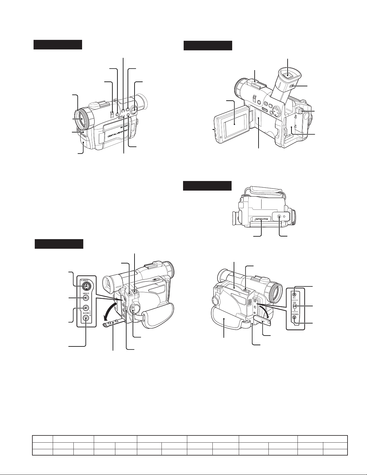
3. PART NAMES
For details on the use of each control.
VL-WD255U
Left view
W/B (White Balance) button
CAT'S EYE switch
Lens hood
Zoom lens
Remote sensor
Stereo microphone
GAMMA/BRIGHTER button
AUTO ON/OFF button
Operation button
MENU/DISPLAY button
Media Selection switch (TAPE/CARD
selection switch)
Left view
LCD monitor
LCD monitor
OPEN release
button
Bottom view
Viewfinder
Zoom microphone
mounting hole
Diopter adjustment
Power source
PUSH release
button
Power source
mounting surface
Lithium battery
compartment door
Card slot cover Tripod socket
Hand strap
Right view
S-VIDEO socket
VIDEO jack
AUDIO L jack
AUDIO R jack
STILL button
Jack cover
Power Zoom Wide angle/
Telephoto control/
VOLume control
Power switch (CAMERA/VCR
select switch)
RECord START/STOP button
10. ADJUSTING THE ELECTRICAL CIRCUITS
[Making adjustments]
Adjusting the servo system controller and related parts
1. Setting the system codes
Replacement of IC703 E2PROM requires the following data to be set in this order.
Cassette compartment door
Cassette compartment door release
PC connection
jack
DV terminal
EarPHONES
jack
Jack cover
Speaker
[Procedure]
Set the unit to the VCR mode and set the data for each address.
Code
Address 01 09 02 0A 03 0B 04 0C 05 0D 07 0F
Data
1. Model code 2. Destination code 3. Specification code 4. Menu selection code 5. Software switching code 6. Calender switching
04 FB
01 FE 14 EB 00 FF 00 FF 01 FE
3
Page 4
VL-WD255U
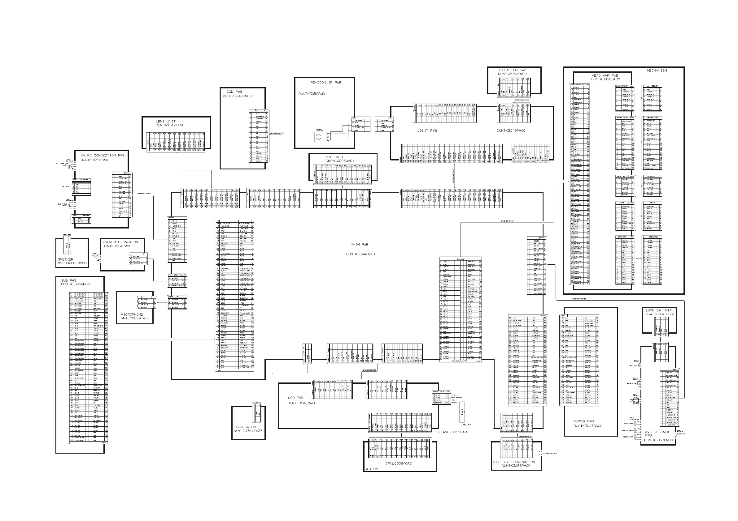
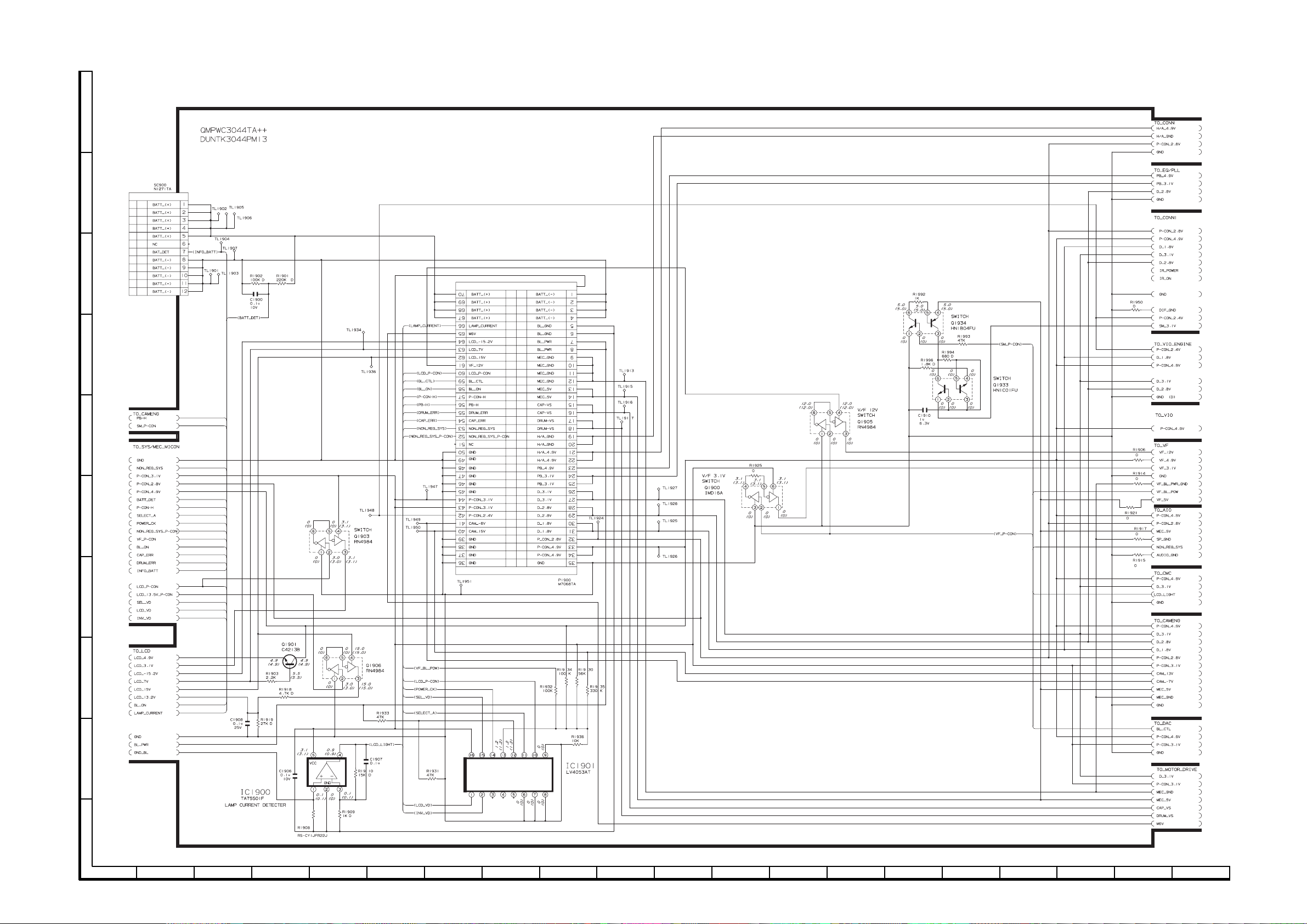
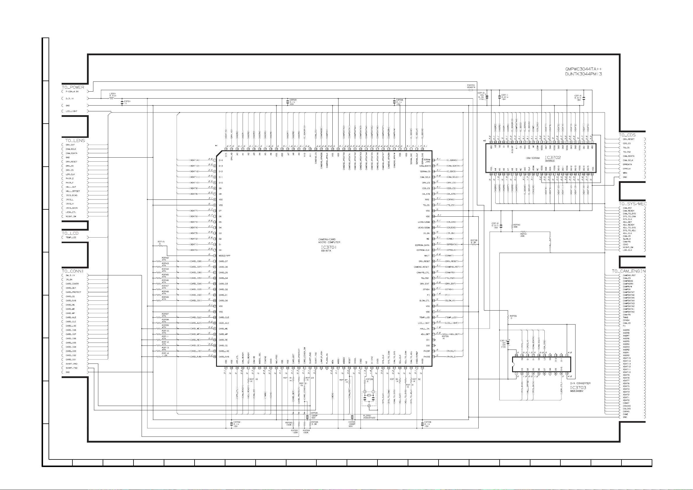
14. SCHEMATIC DIAGRAMS 14-1. OVERALL SCHEMATIC DIAGRAM
J
I
H
G
F
E
D
C
B
A
1234567891011 12 13 14 15 16 17 18 19 20
4–5
Page 5
VL-WD255U
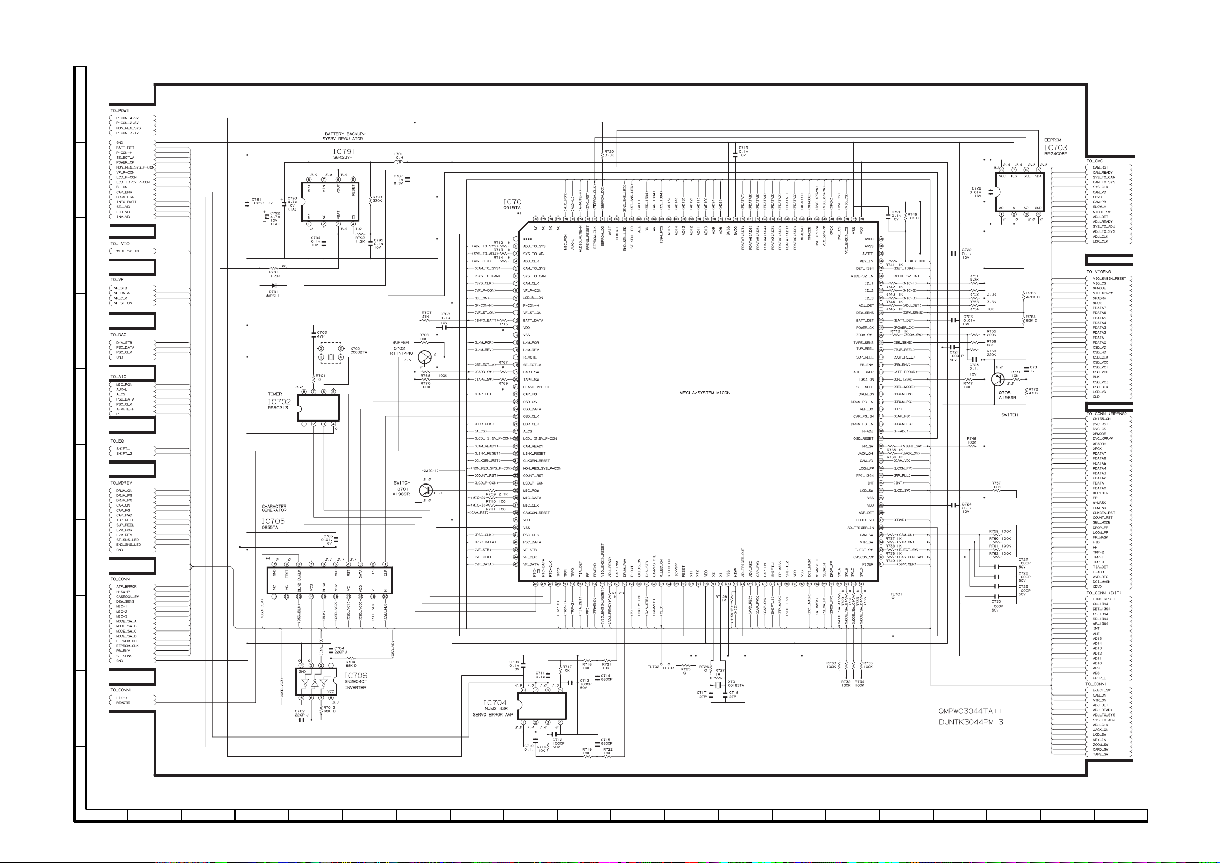
14-2. MEC/SYS_MICON SCHEMATIC DIAGRAM
J
I
H
G
F
E
D
C
B
A
1234567891011 12 13 14 15 16 17 18 19 20
6~7
Page 6
VL-WD255U
14-3. POWER1 SCHEMATIC DIAGRAM
J
I
H
G
F
E
D
C
B
A
1234567891011 12 13 14 15 16 17 18 19 20
8~9
Page 7
VL-WD255U
14-4. CAM/CARD MICON SCHEMATIC DIAGRAM
J
I
H
G
F
E
D
C
B
A
1234567891011 12 13 14 15 16 17 18 19 20
10~11
Page 8

VL-WD255U
14-5. MIC AMP SCHEMATIC DIAGRAM
J
I
H
G
F
E
D
C
B
A
1234567891011 12 13 14 15 16 17 18 19 20
12~13
Page 9

VL-WD255U
14-6. POWER SCHEMATIC DIAGRAM
å AND SHADED COMPONENTS=SAFETY RELATED PARTS
J
I
H
G
F
E
D
C
B
A
1234567891011 12 13 14 15 16 17 18 19 20
14~15
Page 10

VL-WD255U
14-7. JOINT SCHEMATIC DIAGRAM
J
I
H
G
F
E
D
C
B
A
1234567891011 12 13 14 15 16 17 18 19 20
16~17
Page 11

VL-WD255U
15. SEMICONDUCTOR LEAD IDENTIFICATION
93
92
81
80
73
72
61
51
41
37
33
29
25
19
1
60
50
40
36
32
28
24
18
ADS933Y
IX0916TA
BH7277KV
BH7275KV
MB3825A
BA7761KV
LR38610
IR3Y29AM
LZ9GH23
47
41
37
31
26
21
19
17
15
13
10
9
12
14
16
18
20
25
30
36
40
46
CXA3503R
MB88344F
UPC2391G
LB11990W
MM1449XQ
BBH7761KV
IX0748TA
AN2536FH
28
37
43
49
55
61
76
91
109
121
139
138
120
108
90
75
60
54
48
42
36
27
36
48
56
64
72
80
100
120
144
160
184
IX0850TA
IX0809TA
IX0707TA
IX0915TA
18
Page 12

16. PRINTED WIRING BOARD ASSEMBLIES MAIN PWB
Component Side SIDE B
VL-WD255U
J
TL808
R5804
R5805
TL703
C1801
C2804
C2803
C2802
R3437
C3423
C3419
C3417
C3411
TL4437
Q1701
R1723
C1712
TL816
TL817
TL823
TL812
TL811
TL809
TL807
TL805
TL702
R3471
IC3403
C3457
C3475
R3423
C3481
C3421
C3409
Q3405
TL3338
R3499
TL4438
TL4439
TL3364
TL3365
TL3350TL3345
R4414
TL1925
TL3371
TL3343
R1728
R1711
R1710
C1717
C1714
R1722
TL1705
C1719
TL819
TL815
TL810TL813TL814
TL804TL806
TL803
TL802
R1804
R3469
R3451
R3450
TL3401TL3403
FL3401
TL3366
TL4436
TL4440
TL3351
TL3355
TL3341
R1727
C1718
C1724
R1712
TL818
TL801
TL1801
TL1800
R1800
TL1936
C3456
FL3402
TL3363
TL3358
TL3329TL3315TL3370
C1728
R1713
C1720
C1723
C1721
TL828
TL825
TL822
TL820
TL831
TL834
R1802
Q1800
C1800
R1801
C3453
C3454
TL3379
TL3378
TL3374
TL3372
TL3362
TL3360
TL3356
TL3353
TL3354
TL3319
R1714
TL1702
TL1916
TL1704
R1715
C1726
C1727
C1722
TL1913
R1716
TL830
TL833TL829
TL832
D1800
R3452
R3412C3466C3420
R3411R3410C3414
TL3307
TL3306
TL3380
TL3375
TL3373
TL3368
TL3317
TL1901
C1725C1902
TL1703
TL824
SC801
TL821
R1803C1810
C3455
C3460
TL3377
TL3348
TL3346
TL3316
TL3318
TL3322
TL3324
TL3326
TL3328
TL3330
TL1903
TL3331
TL3332
R1819
IC3404
R3495
R3494
TL3312
TL3321
TL3323
TL3325
TL3327
TL3320
TL3336
TL1907
TL826
TL827
C3458
TL3335
TL3340
IC3405
R3474
TL3304
TL3313
TL1904
SC900
TL1934
R3453
R3493
R3492
C3462
R3475
TL3302
TL3311
TL3309
TL3314
TL1905
TL1926
TL1906
TL1902
TL6602
C6612
R3425
R3424
C3412
L3401
R4450
TL4405
R4441
R4416
Q1401
R1452
C1703
C2800
C2801
R3422
C3413
R3430
C3403
C3401
R3401
R4403
C4403
R7860
C4413
C4402
IC4472
TL5022
TL1948
TL1950
TL2801
TL2802
L3405
C3479
C3474
R3413
R3442R3404
R3441
C3443
C3442
TL3344
C7807
R7810
R7806
R7800
C4430
C4421C4419
IC4471
R4402
TL1915
L1702
C1702
C1701
TL1947
C1705
TL1949
TL2800
R3438
R3449
IC3401
R3414
R3409
Q3401
R7859
C7821
R7811
C7804
R7808
R7809
R7802
R7801
C4401
C4410
C4441
R1721
R1709
R1704
C1704
C1706
P6602
TL6607
L2801
IC2800
R3439
R3443
C3408
C3405
C7850
C7811
C7822
R7805
C7802
C4417
L4402
C4404
C4440
R1734
R1708
R1707
C1707
L2800
R2803R2804
R2806R2808
R2805R2807
R2802
R3447
Q3403
R3440
R3435R3491R3480R3482
R3407
C7810
R7804
R7807
C7805
C7800
R4401
R1733
C1709
C1711
TL6605
R2801
R3457
C3459
R3444
R3448
R3436
R3463C3430R3490R3481C3444
R3462C3429C3471C3434C3431
C3410
R3406
C3465
R3496
R3489Q3406
IC7801
C7808
R7803
C7806
R7812
TL7823
R1725
R4440
R1726
R1720
C1708
IC1701
C1715
C1713
C1716
L1701
TL6606
R5801
R5800
R5803
R5802
R2800
R3468
C3452
TL3406
R3434
R7813
R7814
L7800
L4401
R1724
TL1701
TL1917
C1710
TL5036
C6646
C603
C633
R4453
D4451
R4473
Q4471
R4477
Q4472
R4424
R4428
R1403
R1404
R1453
TL5035
R6652
R6653
R660
Q604
IC601
TL4451
D4452
L4451
C4435
R4425
C4405
R4488
Q4481
Q1434
R1438
R1439
C1437
C1440
TL5004
TL5033
C6630
R6654
C6645
R671
C632
X4451
R4451
R4478
C4424
R4487
C1436
R1440
R1441
C1441
R6629
Q605
R661
R662
R672
C625
C4427
C4423
R4475
C4420
C4482
C4436
Q4482
R1442
IC1431
C1439
TL5032TL5034
TL5031
C6621
C6622
R6628
R6651
C6644
R603C616
R616
C606
R654
C631
R4454
C4454
R4456
R4452
C4451
C4426
C4422
C4472
R1454
C1404
C1409
TL1431
R1415
C1438
R1402
R1419
IC6601
C6642
R617
R618
R613
R636
R638
R631
TL4433TL4435
TL4434
TL4417
TL4416
C4412
R4435
C1405
C1408
Q1405
R1413
R1414
R6650
C617
C7843
C4411
R1408
C1407
R5007
FB6605
R6648
R6649
C6647
R6647
TL602
C623
C624
TL601
C628
C629
R635
C645
R4494
TL4429
R4415
Q4434
R4436
SC5001
R6646
L6601Q6604
R3446
C3432
R3488
TH3401
R3445
Q3404
R3478
C7837
C4431
TL4428
R4404
C4406
TL5011
TL6604
R6627
C6648
TL3352
L3404
FL3403
L3402
R7855
R7854
R4407
R4405
Q4433
R4443
R4422
R4426
R4423
D1402
IC1401
D1403
C1406
P6601
TL6603
R6602
C6620
R3486R3432
R3454
R3479
R7843
R7851
C7842C4432
R4406
TL5016
R6608
R6609
C6618
C6619
C3436
C3425
TL7800
R7852
C7841
IC4401
R4408
Q4442
TL8800
R4420
C1413
C1412
TL5017
R6606
FB6610
R6607
C6601
C6602
C6609
C6610
R6615
R6617
C6613
R6621
C6617
R6658
R6657
Q6602
R3427R3426
R3473
R3472
C3467
R3416
R3417
C3478
R3415
R3402
C7844
R7841
C7815
D7800
R4409
R4410
R4442R4437
TL4403
R4421C4407
R4429R4499
C1411
TL5019
C6606
C6603
C6608
R6613
R6618
C6615
R6623
R6626
C3473
IC3402
R3487
C3433
C3426
R3428
R3421
C3424
TL3333
C3477
R3419
C3476
R3420
R3470
C3470
C3418
C3416
C3415
R3418
L7801
R4411
Q4441
R4418
R1451
C1416
C1418
C1417
R1421
R1461
R1462
TL5021
TL6601
C6607
R6614
C6611
R6619R6616
C6614
R6625
R3429
C3406
C3402
R4413
TL4404
C1410
C1414
R1729
R1730
R1705
R1706
R1731
R1732
R5006
C6604
R6612
C6605
R6624R6620
C6616R6622
R6656
C3428
R7847
C7816
R7858
R7857
R7856
C7813R7827
TL4415
R4412
Q4440
R4430R4427
C4409R4419
R4417C4408
R5005
SC5002
TL5047TL5046TL5045TL5044
TL5041
TL5037
TL5039
TL5042
C6628
TL5038
TL5043
C6624
C6623
C6626
TL29
C207
Q601
C636
TL571
TL563
TL557
TL555
TL558
TL28
TL23
C218
R651
C651
TL553
TL568
TL551
TL552
TL556
L601
C208
Q1431
TL5108
Q6603
C6633
C6632
C642
TL567
TL566
TL569
L1404
R621
R663
Q602
C646R656
C690
TL554
C638
C639
TL565
Q4461
R4463
C4464R4468
R4467
TL202TL203
TL5135
TL5101
TL5118
TL5105
TL5113
R6630
R6632
R6633
R6635
R6634
R6640
C6638
R6644
Q608
R610
TL560
TL561
R639
C637
R640
TL564
C640
R4464
TL5115
TL5114
TL5140
TL5106
TL5112
C6627
C6636
R6642
R6659
R6643
TL603
TL572
TL559
TL570
TL562
R4462
R4465
Q4462
L4481
L1431
TL1410
TL5006
TL1924
TL5009
TL5107
TL5109
TL5111
R6631
C6637
R6641
R6661
C6639
C6640
R609
R688
R686
C686
C605
R670
R4461
C4462
C4465
R4469
R4460
C4463
C4461
Q4432
C215
TL207
C212
R1401
R5004R5003
TL5007
TL5110
TL5008
TL5010
TL5012
TL5015
C6629
C6631
R6638
R6639
R6660
C6641
R6645
R685
Q4431
C1434
Q1433
C6643
R687
C685
C634
R4466
IC4461
L4461
C4483
R4485
C4485
C4481
C1432
R1432R1431
Q1432
C1433R1433
R1435R1434
R1437
C1435
R1436
C1431
TL1951
TL5013
C4466
R4474
R4486
TL5002
TL5001
I
R6636
C6634
R6637
C6635
H
G
TL604
TL605
L603
Q606
R641
F
E
TL37
TL35
TL27
TL26
TL36
TL34
TL32
TL31
TL30
TL24
TL8840
TL8842
TL5138
TL8860
R203
R204
R218
R205R209R208R206R210
FB35
TL5129
TL5127
L101
C202
TL208
R207
R215
R217
R213
R214
R216
R212
R202
R211
TL5128
TL5125
TL21
C220
C217
TL209
C214R219
TL5123
TL25
TL22
C213
TL5139
TL5130
TL5121
TL33
TL38
TL5132
TL5137
TL5119
TL5120
TL5133
TL5126
TL5102
C1402
TL5134
TL5131
TL5122
TL5124
TL5104
TL5103
C641
C211
TL212
IC202
C210
L1402
C1415
TL210
TL211
R201
TL8833
TL8835
TL8837
TL8839
TL8848TL8841
TL8846
C204
TL8844
TL8831
TL8832
TL8843
TL8834
TL8845
TL8836
TL8847
TL8838
TL8849
D
IC201
C
R220
Q201
C219
R221
R222
Z2
B
TL1927
FB201
TL8821
C201
C205
TL1928
C24
FB204
FB202
C203
C206
R246
A
12345678910
19
Page 13

VL-WD255U
- M E M O -
20
Page 14

VL-WD255U
Ref. No. Part No. ★ Description Code
17. REPLACEMENT PARTS LIST/
EXPLODED VIEWS
ELECTRICAL PARTS LIST
Parts marked with
set. Be sure to replace these parts with specified ones for maintaining
the safety and performance of the set.
Les pièces marquéss
l'appareil. Ne remplacer ces pieces que par des pièces dont le numéro
est spécifié pour maintenir la sécurité et protéger le bon fonctinnement
de l'appareil.
"
in USA: Contact your nearest SHARP Parts Distributor. For loca-
in CANADA: Contact SHARP Electronics of Canada Limited
★MARK : SPARE PARTS-DELIVERY SECTION:ALL JAPAN
To have your order filled promptly and correctly, please furnish
the following informations.
"å"
are important for maintaining the safety of the
"å"
sont importantes pour maintenir la sècurité de
HOW TO ORDER REPLACEMENT PARTS
tion of SHARP Parts Distributor,
Call Toll-free 1-IBE800-SHARP
Phone (416) 890-2100.
1. MODEL NUMBER 2. REF. NO.
3. PART NO. 4. DESCRIPTION
5. PRICE CODE
å MARK: SAFETY RELATED PARTS
å PIECES: RELATIVES A LA SECURITE
"
Ref. No. Part No. ★ Description Code
R1994 VRS-CZ1JF681D 680 1/16WMetal Oxide AB
R1996 VRS-CZ1JF182D 1.8k 1/16W Metal Oxide AB
R3707 VRS-CZ1JF473J 47k 1/16WMetal Oxide AA
R3708 VRS-CZ1JF473J 47k 1/16WMetal Oxide AA
R3709 VRS-CZ1JF473J 47k 1/16WMetal Oxide AA
R3710 VRS-CZ1JF473J 47k 1/16WMetal Oxide AA
R3711 VRS-CZ1JF473J 47k 1/16WMetal Oxide AA
R3712 VRS-CZ1JF473J 47k 1/16WMetal Oxide AA
R3713 VRS-CZ1JF473J 47k 1/16WMetal Oxide AA
R3714 VRS-CZ1JF122J 1.2k 1/16W Metal Oxide AA
R3721 VRS-CZ1JF102J 1k 1/16WMetal Oxide AA
R3722 VRS-CZ1JF104J 100k 1/16WMetal Oxide AA
R3742 VRS-CZ1JF473J 47k 1/16WMetal Oxide AA
R3743 VRS-CZ1JF473J 47k 1/16WMetal Oxide AA
R3744 VRS-CZ1JF473J 47k 1/16WMetal Oxide AA
R3745 VRS-CZ1JF473J 47k 1/16WMetal Oxide AA
R3746 VRS-CZ1JF473J 47k 1/16WMetal Oxide AA
R3747 VRS-CZ1JF473J 47k 1/16WMetal Oxide AA
R3748 VRS-CZ1JF473J 47k 1/16WMetal Oxide AA
R3749 VRS-CZ1JF473J 47k 1/16WMetal Oxide AA
R6605 VRS-CZ1JF000J Not used. —
R6610 VRS-CZ1JF000J Not used. —
MISCELLANEOUS PARTS
FB6605 RBLN-0242TAZZY Balun, BLN-0242TA AB
FB6610 RBLN-0242TAZZY Balun, BLN-0242TA AB
DUNTK3046PM00
CCD PWB UNIT
RESISTOR
R95 VRS-TV1JD000J 0 1/16WMetal Oxide AA
PWB ASSEMBLY IS NOT REPLACEMENT ITEM
L'ASSEMBLANGE P.C.I. EST UN ARTICLE NON REMPLACABLE
Ref. No. Part No. ★ Description Code
PRINTED WIRING BOARD ASSEMBLIES
(NOT REPLACEMENT ITEM)
DUNTK3044PM13 MAIN PWB Unit —
DUNTK3046PM00 CCD PWB Unit —
DUNTK3047QA00 POWER PWB Unit —
DUNTK3049PM00 JOINT PWB Unit —
DUNTK3053PM00 AVS DC JACK PWB Unit —
DUNTK3044PM13
MAIN PWB UNIT
INTEGRATED CIRCUITS
IC701 RH-iX0915TAZZQ IX0915TA, Mecha/System BC
Micon
IC3701 RH-iX0916TAZZQ IX0916TA, Camera/Card BD
Micro Computer
TRANSISTORS
Q1933 VSHN1C01FU/-1 HN1C01FU AC
Q1934 VSHN1B04FU/-1 HN1B04FU AC
CAPACITORS
C24 VCSATJ1VJ685M 6.8 35V Tantalum AE
C1910 VCKYCY0JB105K 1 6.3V Ceramic AC
C3704 VCKYCZ1HB102K 1000p 50V Ceramic AB
DUNTK3047QA00
POWER PWB UNIT
RESISTORS
R931 VRS-CZ1JF272D 2.7k 1/16WMetal Oxide AB
R9931 VRS-CZ1JF225J 2.2M 1/16W Metal Oxide AA
DUNTK3049PM00
JOINT PWB UNIT
CAPACITOR
C2021 VCSATA1AJ106M 10 10V Tantalum AC
MISCELLANEOUS PARTS
SC2023 QSOCZ0072TAZZQ Socket, 24Pin AP
SW2021 QSW-M0016TAZZ Switch AD
DUNTK3053PM00
AVS DC JACK PWB UNIT
RESISTOR
R2012 VRS-CZ1JF102J 1k 1/16WMetal Oxide AA
R1992 VRS-CZ1JF102J 1k 1/16WMetal Oxide AA
RESISTORS
R1993 VRS-CZ1JF473J 47k 1/16WMetal Oxide AA
21
Page 15

VL-WD255U
VL-SD20U
Ref. No. Part No. ★ Description Code
CABINET PARTS LIST
1 DCABA6222LM01 Cabinet A Preparation AY
1-1-2 GCOVH1274TASA DV Terminal Cover AD
1-1-3 GCOVH1278TAZZ Lid Lock Cover AD
1-1-4 GFTAC1308TAKA Cassette Lid AN
1-1-5 JKNBP0221TASA Cassette Lid Knob AB
1-1-6 LANGK0594TAFW Stay Rear AD
1-1-7 LHLDZ1599TAZZ Lid Lock AD
1-1-8 MSPRT0062TAFJ Lid Lock Spring AB
1-1-9 NSFTZ0161TAFW Cassette Lid Shaft AB
1-1-10 PMLT-0217TAZZ Cassette Lid Spacer A AB
1-1-11 PMLT-0219TAZZ Cassette Lid Spacer C AB
1-1-12 PMLT-0224TAZZ Cassette Lid Spacer D AB
1-1-13 PSHEP0207TAZZ Lock Blind Sheet AB
1-1-14 UBNDT0137TASA Handstrap AL
1-1-15 QEARP0309TAZZ Speaker Earth Sheet AB
1-2 GCOVA1747TAKA SP Cover AC
1-3 LSTYM0034TAZZ Stay Front Ass’y AG
1-5 DUNTK3053PM00 AVS DC Jack Unit —
1-6 DUNTK3051PM00 DV 232C HP Unit —
2 DCABB6254LM02 Cabinet B Preparation AW
2-1 CBTN-0336TA01 KS Operation Button AM
2-1-1 JBTN-0332TASA GUI Button AF
2-3 GCOVH1277TASA LCD Lock Cover AB
2-4 JKNBP0222TASA NR Change Knob AE
2-5 JKNBP0223TASA Mode Change Knob AB
2-6 LHLDZ1605TAZZ NR Change Knob Holder AC
2-7 LHLDZ1606TAZZ
2-8 PSPAZ0363TAZZ LCD Catch Spacer AA
2-10 TLABH0434TAZZ Lithium Exchange Label AB
2-11 PSHEP0206TAZZ Tilt Blind Sheet AC
2-12 DUNTK3052PM00 VCR Operation Unit —
2-13 DUNTK3049PM00 Joint Unit —
2-14 QCNW-2038TAZZ Wire with Lag AC
2-15 TCAUH0284TAZZ Card Caution Label AA
3 CCOVA1743LM01
3-2 PSPAG0133TAZZ Terminal Floating Rubber AB
4 DCOVA1753LM01 Battery Cover Preparation AW
4-1-2 JBTN-0334TASA S/S Button AF
4-2 GCOVA1752TASA Power Knob Cover AH
4-3 GCOVH1273TASA AV Terminal Cover AE
4-4 HDECP0083TASA Battery Nameplate AC
4-5 HDECP0084TASA AV Terminal Nameplate AC
4-6 HDECP0090TASA Power Hole Cover AB
4-7 JBTN-0333TASA Still Button AF
4-8 JBTN-0337TASA Power Lock Button AB
4-9 JKNBP0218TASA Battery Lock Knob AE
4-10 JKNBP0220TASA Power Lock Knob AF
4-11 LANGK0600TAFW Battery Lock Angle AB
4-12 LHLDZ1598TAZZ Power Knob Holder AC
4-13 MSPRC0145TAFJ Battery Lock Spring AA
4-14 MSPRC0146TAFJ Power Lock Spring AA
4-15 PSHEP0184TAZZ Battery Hole Cover AB
5 DCOVA1759LM01 Front Cover Preparation AT
5-1-2 GCOVA1744TASA Lens Hood AD
5-1-3 GCOVA1745TASA Lens Hood Cover A AD
5-1-4 GCOVA1765TASA Lens Hood Cover B AH
5-1-5 GCOVA1761TASA IR Remote Control Light AD
5-1-6 HiNDP0238TASA Lens Hood Nameplate AE
5-1-7 QEARP0297TAZZ
5-1-8 GCOVA1760TASA Front Decoration Cover AC
5-2 HDECA0704TASA Microphone Grille AM
5-3 LHLDZ1607TAZZ Microphone Holder AC
5-4 PFLT-0036TAZZ Microphone Spacer AB
5-5 PMLT-0222TAZZ Microphone Grille Sound AB
6-1 LANGK0606TAFW Lens Fitting Angle AF
7-1 GCOVA1750TAKA V/F Cover Upper AK
7-2 GCOVA1751TAKA V/F Cover Lower AK
7-3 GCOVD1010TAZZ V/F LCD Protection Cover AB
7-4 GCOVH1272TA00 Eye Cap AP
7-5 GCOVH1275TAZZ V/F Front Cover Unit AE
Mode Change Knob Holder
Top Side Cover Preparation
Reception Cover
Microphone Grille Earth Sheet
Insulation Molt
AC
AN
AB
Ref. No. Part No. ★ Description Code
7-6 JKNBZ0096TASA Visibility Control Knob AB
7-7 LANGK0602TAZZ V/F Tilt Unit AM
7-8 LANGK0605TA00 V/F Fitting Angle AH
7-9 LHLDZ1602TAZZ V/F LCD Inverter Holder AC
7-10 LHLDZ1603TAZZ V/F Back Holder AC
7-11 MSPRP0217TAFW Visibility Control Spring AB
7-12 PFLT-0037TAZZ V/F FPC Spacer AA
7-13 PFLT-0038TAZZ V/F Angle Spacer AA
7-14 PLNSV0009TAN2 V/F Lens Unit AH
7-15 PSHEP0198TAZZ V/F Angle Sheet AB
7-16 PSPAG0134TAZZ V/F LCD Spacer AF
7-17 PSPAG0135TAZZ V/F Backlight Spacer AF
7-18 PSPAZ0386TAZZ V/F Spacer AB
7-19 PSPAZ0398TAZZ V/F Visibility Spacer AB
7-20 RLCDV0068TAZZ V/F LCD Panel BM
7-21 KLMPV0052TAZZ V/F Backlight AT
7-22 RUNTK0397TAZZ V/F FPC Unit AX
8-1 CANGK0598LM01 LCD Shield Case Front AH
Preparation
8-1-2 PZETV0413TAZZ LCD Insulation Sheet A AA
8-2 CANGK0599LM01 LCD Shield Case Rear AL
Preparation
8-2-2 PSHEP0185TAZZ LCD Spacer AD
8-2-3 PTPEH0065TAZZ LCD Fixing Tape AF
8-3 CANGK0608LM01 LCD Tilt Unit Preparation BB
8-3-1 GCOVA1748TASA Tilt FPC Cover AC
8-3-2 GCOVA1749TASA Tilt Upper Cover AF
8-4 CCABE6050LM01 LCD Cabinet Preparation AV
8-4-2 HDECP0096TASA LCD Nameplate AE
8-4-3 JBTN-0335TASA LCD Lock Lever AC
8-4-4 MSPRD0081TAFJ LCD Lock Spring AB
8-4-6 GCOVA1754TAKA LCD Decoration Cover AD
8-5 GCOVA1756TAKA LCD Front Cover AL
8-7 PSHEP0108TA01 Prism Sheet AG
8-8 PSHEP0110TAZZ Diffusion Sheet AD
8-9 PGiDM0036TAZZ Light Guide Plate AG
8-10 PMiR-0039TAZZ Reflection Sheet AD
8-11 DUNTK3048QA00 LCD PWB —
9 GCOVA1757TAKA Bottom Cover AG
9-1 PMLT-0227TAZZ Power to Main Cushion AB
9-2 PMLT-0226TAZZ Sub to Main Cushion AB
9-3 PMLT-0228TAZZ Power to Joint Cushion AB
9-4 PMLT-0228TAZZ Sub to Joint Cushion AB
9-5 PMLT-0229TAZZ Joint to Main Cushion AB
10 GFTAA1003TASA Card Lid AD
11 LANGK0595TAFW Mechanism Fitting Angle AH
12 LANGT0467TASA Shoe ANG AE
13 PSPAG0132TA00 Mechanism Floating Rubber AB
14 GCOVH1276TASA Adjust Hole Cover AC
15 TLABH0435TAZZ FCC Label AB
16 TLABM2215TAZZ Model Labe AC
17 QSW-Z0362TAZZ Zoom SW Unit AR
18 VSP0020P-968N Speaker AL
19 DUNTK3054PM00 Zoom Microphone PWB —
20 DUNTK3063PM00 Battery Terminal Unit —
21 RMiCC0099TAZZ Microphone AT
22 PLNSA0142TAN1 Lens Unit BX
23 QPWBH3060TAZZ LCD FPC AR
24 QSW-Z0364TAZZ LCD Turn SW AA
28 QPWBH3057TAZZ Joint/Main FPC AF
29 QPWBH3061TAZZ DV/Main FPC AE
30 CLMPV0055QA01 LCD Lamp AU
31 CPNLC0064QA01 LCD Panel BU
32 QPWBH3062TAZZ Ope/Joint FPC AD
a LX-BZ0221TAFC Screw AB
b LX-HZ0063TAFF Screw AA
c XiPSF17P04000 Screw AA
d XiPSN17P04000 Screw AA
e LX-HZ0063TAFN Screw AA
f LX-HZ0079TAFD Screw AB
h LX-HZ0050TAFF Screw AA
j LX-BZ0246TAFD Screw AB
k LX-BZ0247TAFF Screw AB
l LX-HZ0017TAFF Screw AA
22
Page 16

VL-WD255U
Ref. No. Part No. ★ Description Code
SUPPLIED ACCESSORIES
ACCESSORIES
å QACCD0031TAPZ AC Cable AK
QCNW-2016TAZZ A/V Cable AH
QCNW-1957TAZZ DC Cable AT
RRMCG0100TASA Remote Control AN
TiNSE0415TAZZ Operation Manual AK
TiNS-6044TAZZ Kodak Access Guide AC
TiNS-6043TAZZ Pix Lab Use Article AC
QCNW-2022TAZZ 232C Cable AS
å UADP-0321TAZZ AC Adapter BG
UBATL0011TAZZ Lithium Battery AE
UBATi0052TAZZ Battery Pack BG
UBATU0247AJZZ AA Size Battery(x2) AE
CDSKA0059TA01 CD-ROM AK
GCOVH1271TASA Lens Cap AL
TCAUH0293TAZZ Ferrite Core Caution AB
Sentence
RCORF0038TAZZ Ferrite Core(x2) AK
ACCESSORIES
(NOT REPLACEMENT ITEM)
TGANE0071TAZZ Guarantee Card —
TLABK0005AJZZ No. Card(x3) —
PACKING PARTS
(NOT REPLACEMENT ITEM)
Ref. No. Part No. ★ Description Code
SPAKC7630TAZZ Packing Case —
SPAKA6375TAZZ Packing Add. (Bottom) —
SPAKA6376TAZZ Packing Add. (Top) —
SPAKA6377TAZZ Packing Add. —
SPAKF0277TAZZ Packing Add. —
SPAKP6143TAZZ Wrapping Bag —
SPAKP6144TAZZ Side Pad —
SSAKA0105TAZZ Plastic Bag —
SPAKP6129TAZZ Packing Sheet —
23
Page 17

VL-WD255U
VL-SD20U
Ref. No. Part No. ★ Description Code
MECHANISM CHASSIS EXPLODED VIEW
600
610
H
4±0.5
435
8.5±0.5
340
334
341
338
G
342
324
335
340
436
337
332
434
435
d
426
F
434
E
+0.5
1.5
-0
2
347
D
339
331
391
357
b
420
390
a
425
344
401
374
391
375
a
353
+0.5
-0
434
345
434
306
309
386
302
403
C
305
370
371
304
301
361
376
360
Ref. No. Part No. ★ Description Code
429
411~
415
431
313
1 pc.
401
c
428
456
411~
415
377
457
355
1 pc.
402
432
354
383
397
392
351
403
458
356
435
385
502
394
432
466
330
470
b
454
433
402
362
389
436
439
454
452
439
402
308
435
c
365
367
366
440
315
451
307
461
402
395
372
373
396
437
436
363
369
462
459
434
d
434
382
455
384
382
381
383
397
352
393
453
312
436
399
398
438
364
421
311
303
B
430
500
501
430
314
463
A
436
465
435
430
123456
24
Page 18

VL-WD255U
Ref. No. Part No. ★ Description Code
CABINET EXPLODED VIEW
b
H
7-18
7-1
c
A
7-7
7-21
7-22
7-20
7-16
7-3
7-9
f
7-8
d
c
c
G
7-12
7-10
d
p
a
F
t
c
b
h
r
d
h
7-15
6-1
h
q
d
7-17
e
7-13
e
d
d
22
B
C
7-2
12
19
f
D
e
5-5
r
5-1-3
5-1-2
5-1-4
5-1-6
E
5-2
5
D
5-4
5-1-5
5-3
1-1-13
d
c
b
d
d
21
F
J
b
17
1-5
1-3
j
G
p
1-6
d
1-2
1-1-3
1-1-7
1-1-4
d
18
1-1-12
b
1-1-2
1-1-15
c
1-1-14
1-1-8
b
1-1-10
b
1-1-9
j
a
16
1
1-1-6
1-1-111-1-11
d
C
b
B
1-1-5
A
1-1-10
Ref. No. Part No. ★ Description Code
7-4
7-6
7-5
7-11
7-19
P
f
O
9-5
b
4-13 4-9
g
d
10
24
b
O
28
4-11
m
K
2
7-14
3
2-10
2-4
b
3-2
2-6
d
5-1-7
5-1-8
b
b
c
2-5
d
a
2-7
b
2-11
2-14
b
9-4
9-2
B
2-15
2-1-1
32
2-13
14
d
2-8
2-1
2-12
b
9-3
9-1
c
t
A
4
4-12
2-3
4-15
g
e
h
4-6
4-7
4-14
l
2-14
4-8
8-3-2
4-10
4-2
8-4-2
n
c
M
d
N
8-3-1
23
L
R
8-3
30
8-9
N
8-8
8-7
4-4
b
b
4-1-2
n
M
4-3
4-5
b
c
b
E
20
8-4
d
c
8-4-6
c
8-4-4
8-4-3
8-11
8-10
J
o
C
E
Q
G
D
j
F
b
b
q
K
L
13
k
b
13
9
m
11
b
Q
29
8-2-2
8-2
8-2-3
R
31
c
8-1-2
15
8-5
8-1-2
n
8-1
n
123456
25
Page 19

VL-WD255U
(
))
VL-SD20U
Ref. No. Part No. ★ Description Code
18. PACKING OF THE SET
åUADP-0321TAZZ
(AC Adapter)
★SPAKF0277TAZZ
(Packing Add.)
UBATL0011TAZZ
(Lithium Battery)
GCOVH1271TASA
(Lens Cap)
RRMCG0100TASA
(Remote Control)
UBATU0247AJZZ
(AA Size Battery(x2))
UBATi0052TAZZ
(Battery Pack)
RCORF0038TAZZ
(Ferrite Core(x2))
★SPAKP6129TAZZ
(Packing Sheet)
Ref. No. Part No. ★ Description Code
åQACCD0031TAPZ
(AC Cable)
QCNW-2022TAZZ
(232C Cable)
★SPAKA6376TAZZ
(Packing Add.(Top))
QCNW-2016TAZZ
(A/V Cable)
QCNW-1957TAZZ
(DC Cable)
★SPAKP6144TAZZ
(Side Pad)
TiNS-6044TAZZ
(Kodak Access Guide)
TiNS-6043TAZZ
(Pix Lab Use Article)
TiNSE0415TAZZ
(Operation Manual)
TCAUH0293TAZZ
(Ferrite Core Caution Sentence)
★TGANE0071TAZZ
(Guarantee Card)
CDSKA0059TA01
(CD-ROM)
★SPAKA6377TAZZ
(Packing Add.)
★SSAKA0105TAZZ
(Plastic Bag)
★SPAKC7630TAZZ
(Packing Case)
★SPAKP6143TAZZ
(Wrapping Bag)
★SPAKA6375TAZZ
(Packing Add.(Bottom))
★TLABK0005AJZZ
No. Card(x3
26
Page 20

VL-WD255U
Ref. No. Part No. ★ Description Code
Ref. No. Part No. ★ Description Code
27
Page 21

VL-WD255U
VL-SD20U
Ref. No. Part No. ★ Description Code
Ref. No. Part No. ★ Description Code
COPYRIGHT © 2001 BY SHARP CORPORATION
ALL RIGHTS RESERVED.
No part of this publication may be reproduced,
stored in a retrieval system, or transmitted in
any form or by any means, electronic, mechanical,
photocopying, recording, or otherwise, without
prior written permission of the publisher.
D Japan P SMM TQ1111-S
May 2001 Printed in JAPAN
SA. DS
SHARP CORPORATION
AV Systems Group
Quality & Reliability Control Center
Yaita, Tochigi 329-2193, Japan
28
 Loading...