

SHARP VLE780U, VLE785U, VLE785T Service Manual
SERVICE MANUAL
SERVICE MANUAL
SY8A8VL-E780U
LIQUID CRYSTAL CAMCORDER 8 NTSC
VL-E780U
VL-E785U
VL-E780U
VL-E780U
VL-E785U
VL-E785U
VL-E785T
VL-E785T
In this Service Manual, only the differences from VL-E760U/765U are described.
Therefore, for the parts which are not described in this Service Manual, refer
to the Service Manual for VL-E760U/765U (S38N2VL-E760U).
NTSC
8
8
2. SPECIFICATIONS .............................................................................................................................. 2
MODELS VL-E780U/E785U/E785TLIQUID CRYSTAL CAMCORDER
4. DISASSEMBLY OF THE SET............................................................................................................. 3
5. MECHANISM ADJUSTMENT ............................................................................................................. 4
6. ADJUSTMENT OF VCR...................................................................................................................... 4
8. SCHEMATIC DIAGRAMS .................................................................................................................. 8
11.REPLACEMENT PARTS LIST ......................................................................................................... 29
12.PACKING OF THE SET ................................................................................................................... 35
MODELS
In the interests of user-safety (Required by safety regulations in some countries) the set should be restored to its
original condition and only parts identical to those specified
be used.
CONTENTS
VL-E785T
Page
SHARP CORPORATION
This document has been published to be used for
after sales service only.
The contents are subject to change without notice.
1

VL-E780U
VL-E785U
VL-E785T
2. SPECIFICATIONS
Signal System: NTSC standard
Recording System: 2 rotary heads, helical scanning system
Cassette: 8 mm video tape, MP type
Recording/Playback Time: 120 minutes (P6-120)
Tape Speed: 14.345 mm/second
Pickup Device: 1/4" (6.4mm, effective size: 4.5 mm) CCD image sensor (with approx.
270,000 pixels including optical black)
Lens: 16 × power zoom lens (F1.4, f=4.0-64.0 mm) and full-range auto focus
Lens Filter Diameter: 46 mm
Monitor: 4" (10.1 cm) full-color LCD screen (TFT active matrix)
Microphone: Electret monaural microphone
Color Temperature Compensation: Auto white balance
Minimum Illumination: 0.8 lux (5 lux measured by EIA standard) (with gain-up, F1.4)
Video Output Level: 1.0 Vp-p 75-ohm unbalanced
Audio Output Level: –8 dBs, impedance less than 2.2 kohms
Speaker Output: 200 mW
Power Requirement: DC 3.6V
Power Consumption:
Operating Temperature: 0°C to + 40°C (32°F to 104°F)
Operating Humidity: 30% to 80%
Storage Temperature: –20°C to +60°C (–4°F to 140°F)
Dimensions (approx.): 7
Weight (approx.): 1.57 lbs (710g)
5.3W (during camera recording in full auto mode with zoom motor off,
Extend Zoom, DIS and Snapshot functions off, and backlight in normal
mode)
5
/32" (W) × 4 9/32" (H) × 3 7/8" (D)
[182 mm (W) × 109 mm (H) × 99 mm (D)]
(without battery pack, lithium battery, video cassette, and lens cap)
AC Adapter/Battery Charger
Battery Pack BT -H22
UADP-0274T AZZ(VL-E780U/E785U)
UADP-0275T AZZ(VL-E785T)
Dimensions (approx.): 2
Power Requirement: AC 110-240 V, 50/60 Hz
DC Output: 4.5 V
Power Consumption: 16 W
Dimensions (approx.): 2
31
/32" (W) × 2" (H) × 5 5/16" (D)
[75 mm (W) × 51 mm (H) ×
135 mm (D)]
Weight (approx.): 0.65 lbs (295 g)
Specifications are subject to change without notice.
*Minimum illumination: Since there is no widely accepted testing procedure for determining minimum illumina-
SERVICE INFORMATION (For the U.S.)
For the location of the nearest Sharp Authorized Service, or to obtain product literature, accessories,
supplies or customer assistance, please call 1-800-BE SHARP (1-800-237-4277) or visit SHARP's
tion capability, lux ratings are comparable only between models from the same
manufacturer.
web site (http://www.sharp-usa.com)
DC Output: 3.6V
1
/8" (W) × 3/4" (H) × 2 7/32" (D)
[54 mm (W) × 19 mm (H) ×
56 mm (D)]
Weight (approx.): 0.30 lbs (136 g)
2
VL-E780U
VL-E785U
VL-E785T
4. DISASSEMBLY OF THE SET
Area A
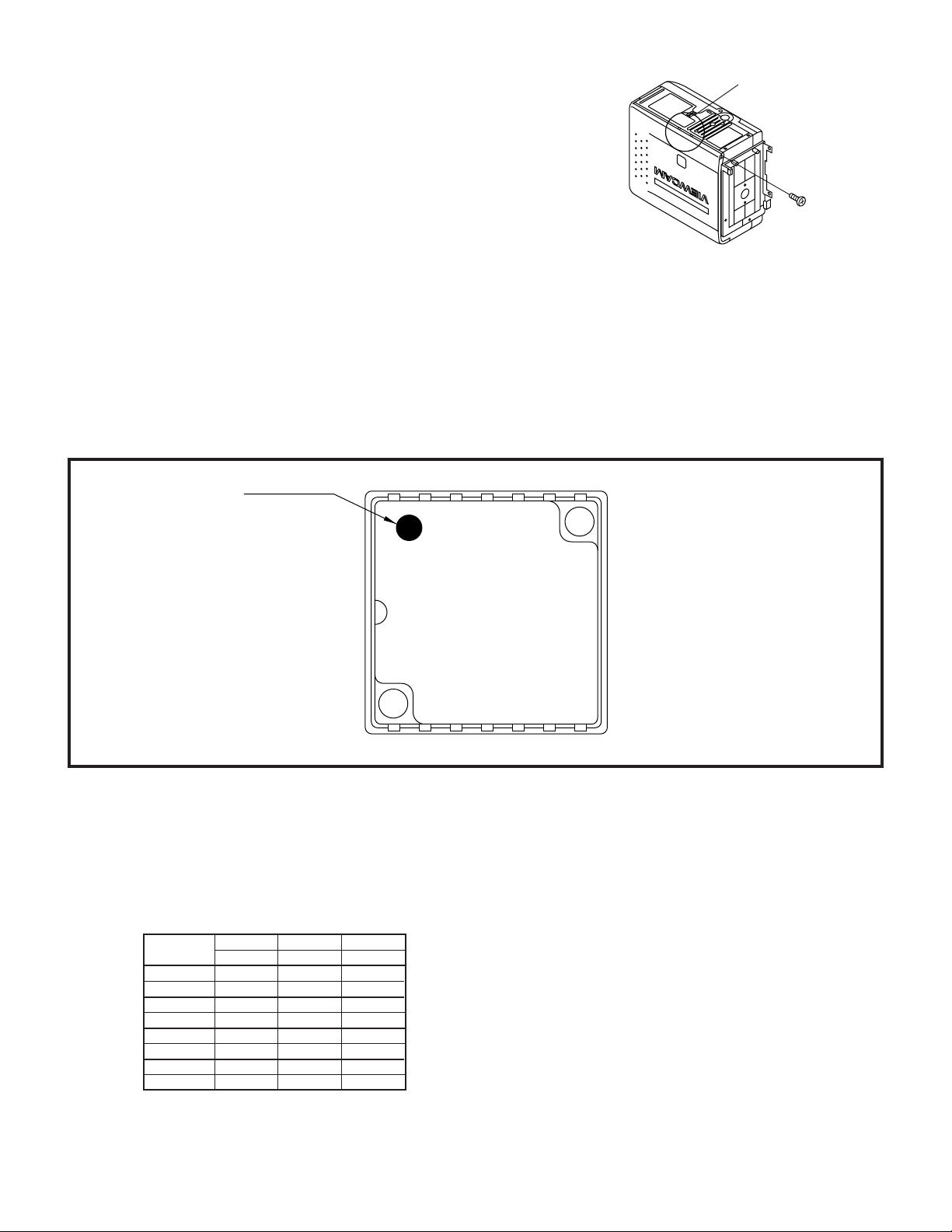
4-2. Disassembly of the VCR main body
1. Removal of the VCR lid shaft
(1)Remove one screw ((j)LX-HZ0063TAFC).
(j)
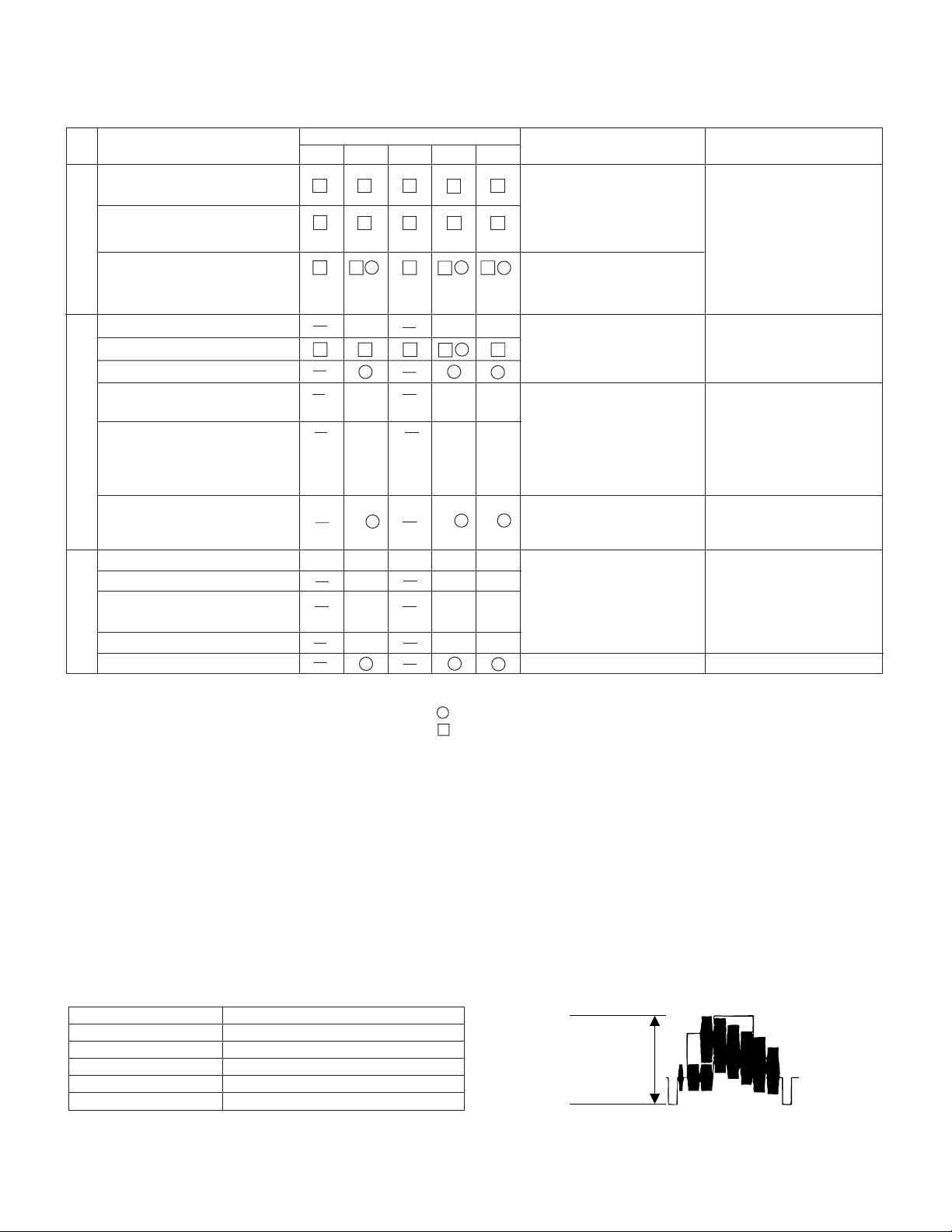
4-3. REPLACEMENT OF CCD SENSOR
4-3-1. BEFORE REPLACEMENT
1) The CCD image sensor is more sensitive to electrostatic breakage than C-MOS LSI. Therefore sufficient means to
prevent electrostatic damage must be taken when it is replaced.
• Ground the soldering iron.
• Ground also the human body, using the wrist strap(through an 1 Mohm resistor).
• Until the CCDsensor is mounted on the PWB, fit it to the conductive sponge, and short-circuit the foot lead.
2) Take utmost care so that the surface glass of CCD sensor and optical filter are not contaminated and damaged. If any
contamination is found, for example fingerprint, wipe it off with silicon paper or clean chamois skin.
3) When replacing the CCD sensor, use the antistaic grounded soldring iron, and perform quickly soldering.
Index Mark
17
JAPAN
SHARP
LZ2413H5
YYWWXXX
14 8
4-4. INITIAL SETTING OF E2PROM IC
4-4-2. IC702 (E2PROM)
When the IC702 has been replaced, make the following settings and adjustments.
1. Remove the backup battery (CR2025)
2. Turn power switch to CAMERA
3. Setting up the V ADJ mode as follows.
* After press the CONTINUE key, press the VCR ADJ key on service remote control (RRMCG0033TASA).
address data data data
03 F8 FA FE
0B 07 05 01
01 00 00 00
09 FF FF FF
04 00 00 00
0C FF FF FF
02 01 01 07
0A FE FE F8
E780U E785U E785T
3
VL-E780U
500±20mVp-p
VL-E785U
VL-E785T
5. MECHANISM ADJUSTMENT
5-2. Items and timings of inspection and maintenance
5-2-1. Inspection and maintenance list
Checking/Maintenance point
Tape travel system
Tape travelling route
(Refer to Section)
Drum (Refer to Section)
Video head
Timing belt
Pinch roller
Capstan D.D. motor
Driving system
Relay Pulle shaft
Pulle gear shaft
Drive gear shaft
Loading motor
Performance check
Abnormal sound
PB/VS-REW take-up torque
PB/VS-REW back tension
torque
Tu brake
HC (Head Cleaner)
Oil:
Grease: MORYCOAT YM-103/X5-6020
Screw locking agent: THERE BOND 1401B
Cleaning liquid: Industrial-use ethyl alcohol
Usage time (hrs.)
500 1,000 1,500 2,000 3,000
★★★
∆∆∆
∆∆∆
★★★
★★★★★
★★★
★★★
★★★
: Replace.
: Clean.
Possible symptom
encountered
• Lateral noise
• Unclean head
• Screen shaking
• Improper S/N ratio
• No color appears.
• Tape does not run.
• Tape slackens.
• Screen shakes.
• Abnormal sound
• Not ejectable
• The specific mode cannot be set.
∆ : Apply oil.
★ : Check.
Remarks
Rollers
• If abnormal rotation or
deflection (significant) is
found, replace the roller.
Other than rollers
• Clean the tape contacting areas. Be sure to
use the specified cleaning agent.
• Replace if failure is
found.
• Apply oil.
(Oil: )
Note:
After oil is applied to the
drive gear shaft, slightly
wipe it off with swab.
• Replace if failure (abnormal sound) is detected.
• If conformance to the
standard is not ensured,
replace part.
5-4. ADJUSTMENT OF MECHANISM TAPE TRAVEL SYSTEM
5-4-3. Adjusting the Si roller height
(2)Adjusting the Si roller
6. ADJUSTMENT OF VCR
6-1. ADJUSTMENT OF VCR SECTION
6-1-5. Y/C circuit adjustment method
2. Adjustment of input Y level
1 Playback the tape such as to set the V/SR mode.
Measuring instrument Oscilloscope
Mode VCR STOP
Input signal Color bar
Measuring point TL801
Adjustment address 32
Adjustment level 500 Vp-p ± 20 mVp-p
4
3. Adjustment of playback Y level
500±20mVp-p
Measuring instrument Oscilloscope
Mode PB
Playback signal Color bar (JiGWR5-5NSP)
Measuring point TL801
Adjustment address 27
Adjustment level 500 Vp-p ± 20 mVp-p
5. Adjustment of Y-FM deviation
VL-E780U
VL-E785U
VL-E785T
Measuring instrument
Oscilloscope
Mode REC/PB (self-playback/recording)
Input signal Color bar
Measuring point TL801
Adjustment address 34
Adjustment level 500 Vp-p ± 20 mVp-p
6-1-7. Adjustment of LCD display circuit
9. Inverter input voltage setting
Measuring point LCD panel display surface
Address 11, 12
Mode VCR AV input
Adjusting method Set the data of address 11 and 12.
Adjustment standard
11=C5
12=A4
Remarks ———————
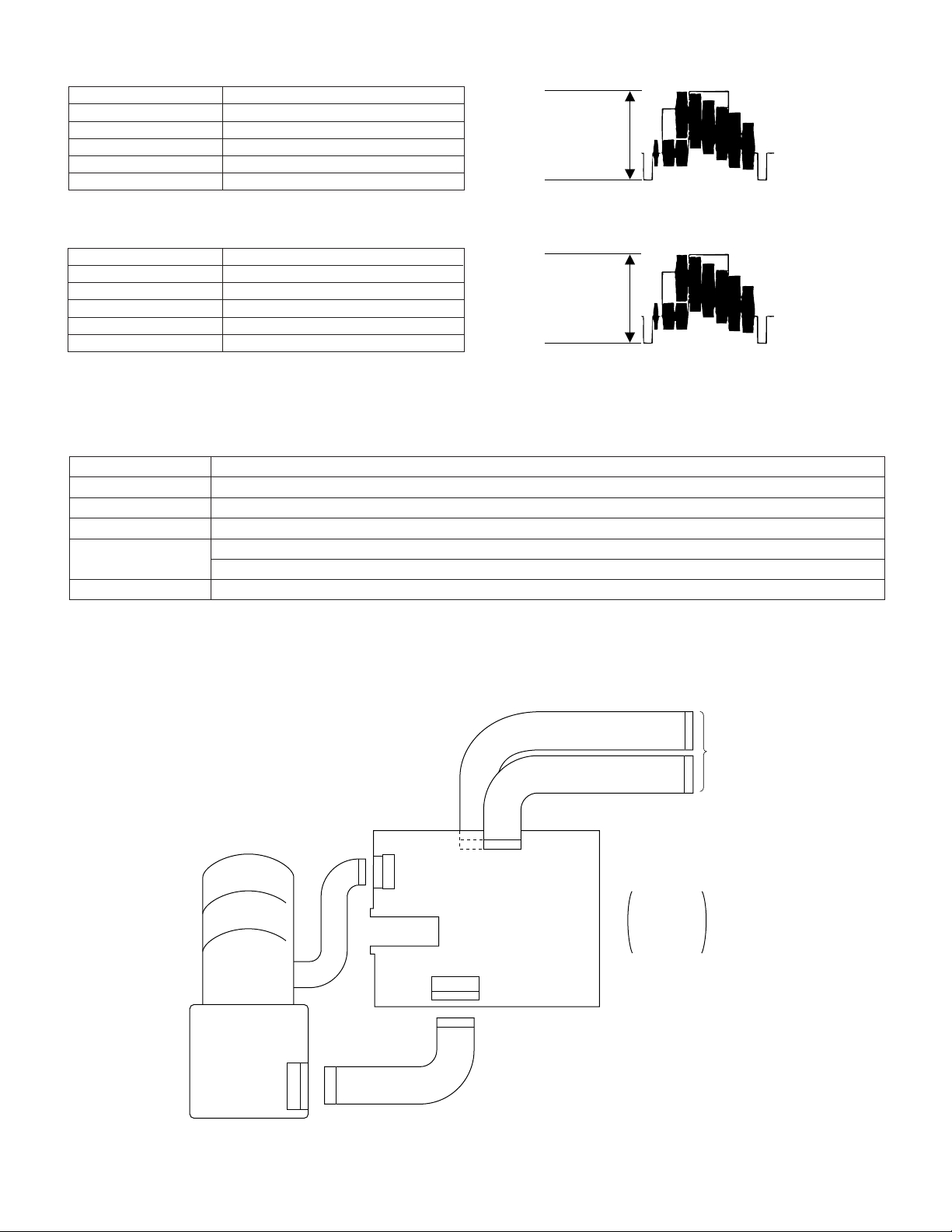
6-2. ADJUSTMENT OF CAMERA SECTION
6-2-1. Servicing of camera section
• Connections for Camera Section Servicing
500±20mVp-p
LENS
CCD PWB
20pin
19pin
QPWBH2815TAZZ
SC6
20pin
SC2
SC3
19pin
QPWBH2814TAZZ
SC4
15pin
17pin
SC2 19 pin
SC3 15 pin
SC4 17 pin
SC6 20 pin
Connect FPC
between the
camera and
the VCR.
5
VL-E780U
VL-E785U
VL-E785T
6-2-2. Adjustment procedures
6-2-2-2. Auto focus adjustment
Measuring instrument
None
Subject —
Tape —
Test point None
Adjustment address 1FF
Adjustment level 09, 0A, 0B
` Preparation for 6-2-2-3~6-2-2-9, setup the camera signal adjustment mode. (Write 00 to the address 1FE.)
6-2-2-3.
Before starting these adjustments, set up the auto focus adjust.
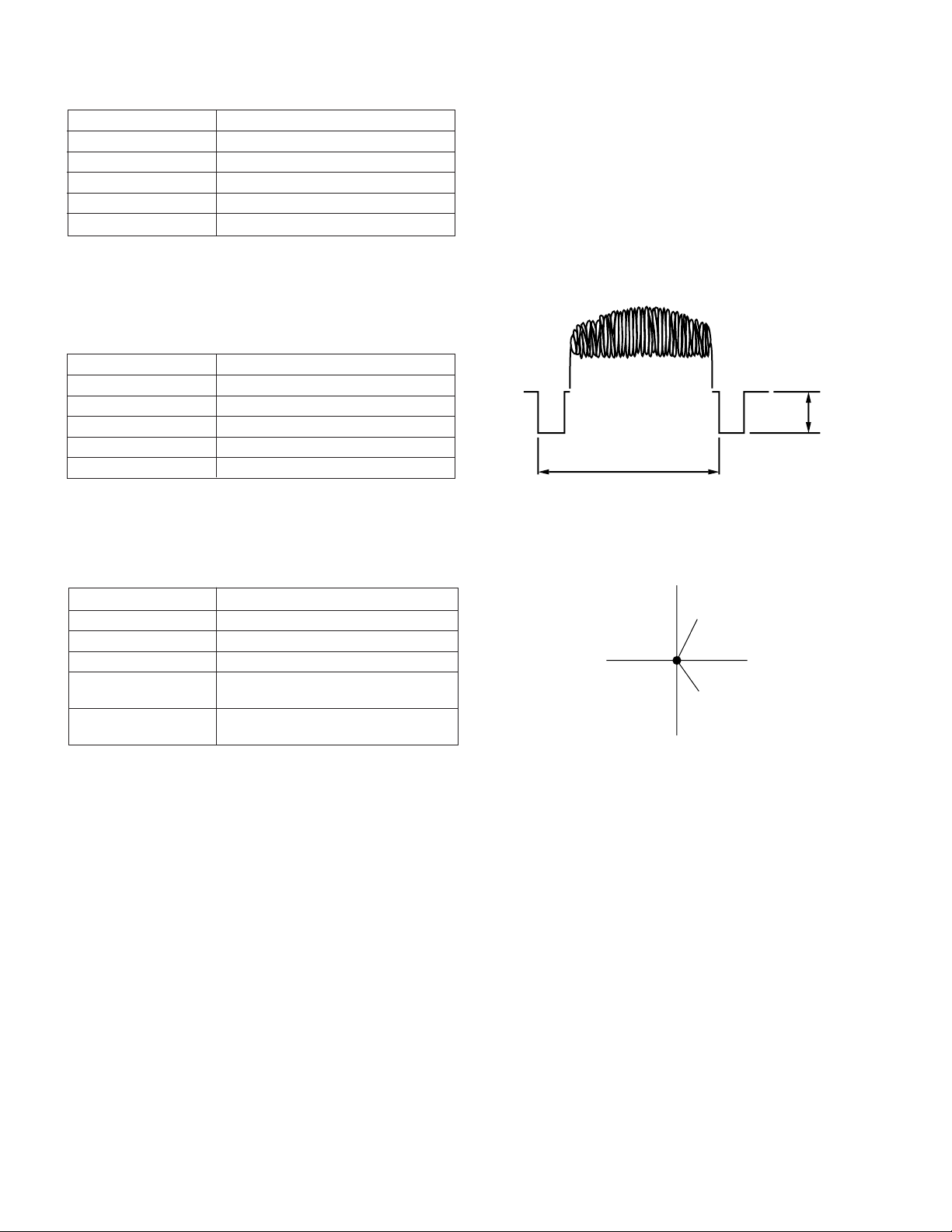
• Sync level adjustment
Measuring instrument
Oscilloscope
Video
Subject Anything
Tape —
Test point
VIDEO OUT (Terminated in 75Ω)
Adjustment address 1F8
Adjustment level 286mVp-p
1H
1) Connect the oscilloscope to the VIDEO-OUT. Adjust the sync level to 286mVp-p.
6-2-2-9.
• Auto white balance adjustment
Measuring instrument
Vector scope
Subject Gray scale
Tape —
Test point
VIDEO OUT (Terminated in 75 Ω)
Adjustment address R-OUT DOOR 016
B-OUT DOOR 018
Adjustment level R-OUT DOOR; 0 ± 3 %
B-OUT DOOR; 0 ± 3 %
1) Attach the color temperature conversion filter (JIGHOYA-LB165) to the front of the lens.
2) Using the addresses R-OUT DOOR 016 and B-OUT DOOR 018, adjust the spot to the center.
3) Take off the color temperature conversion filter.
` Write FF to the address 1FE to exit from the camera signal adjustment mode.
R-Y
Spot
B-Y
Center point
SYNC
286mVp-p
6

- M E M O -
VL-E780U
VL-E785U
VL-E785T
7
VL-E780U
G
H
I
J
K
L
M
1
234 5 6
7
å
å
VL-E785U
VL-E785T
H
G
F
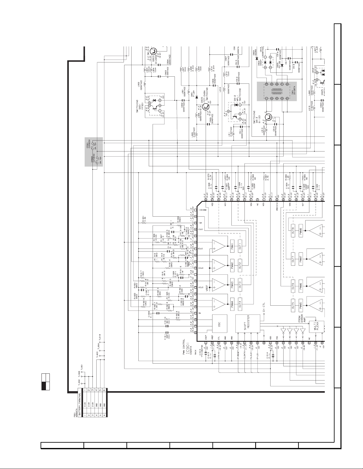
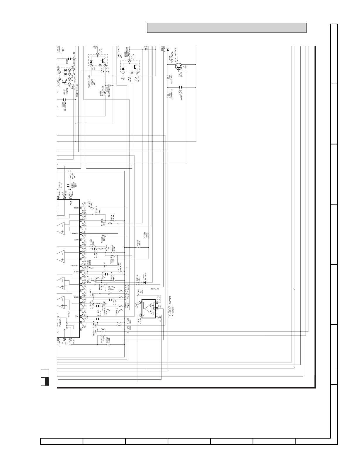
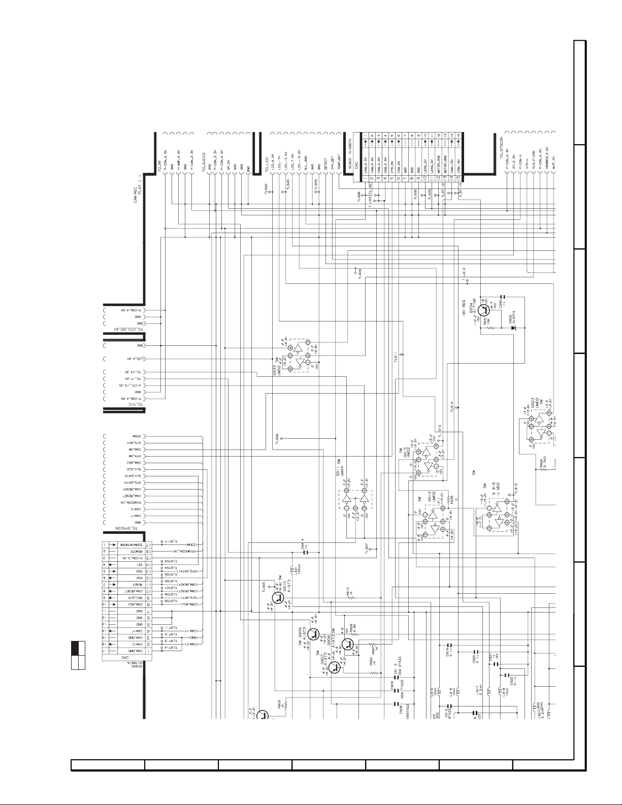
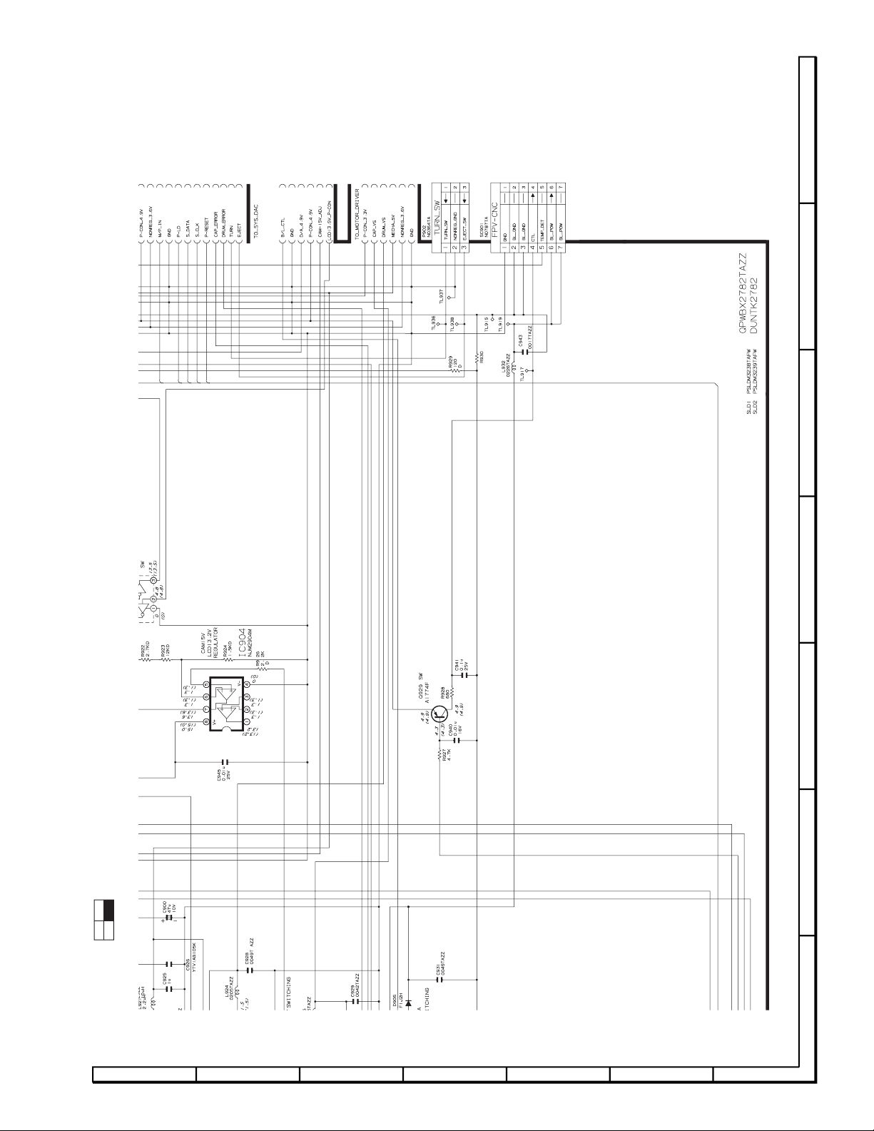
8. SCHEMA TIC DIAGRAMS
8-2. POWER CIRCUIT SCHEMATIC DIAGRAM
E
D
C
B
13
24
A
LOCATION MAP: (1/4)
1234567
8
A
B
C
D
E
F
G
1
234 5 6
7
å
AND SHADED COMPONENTS=SAFETY RELATED PARTS
VL-E780U
VL-E785U
VL-E785T
13
24
LOCATION MAP: (2/4)
78910111213
9
VL-E780U
G
H
I
J
K
L
M
7
8 9 10 11 12
13
VL-E785U
VL-E785T
H
G
F
E
D
C
B
13
24
A
LOCATION MAP: (3/4)
1234567
10
A
B
C
D
E
F
G
7
8 9 10 11 12
13
VL-E780U
VL-E785U
VL-E785T
13
24
LOCATION MAP: (4/4)
78910111213
11
 Loading...