

Page 1
SERVICE MANUAL
SERVICE MANUAL
SY8A8VL-E780U
LIQUID CRYSTAL CAMCORDER 8 NTSC
VL-E780U
VL-E785U
VL-E780U
VL-E780U
VL-E785U
VL-E785U
VL-E785T
VL-E785T
In this Service Manual, only the differences from VL-E760U/765U are described.
Therefore, for the parts which are not described in this Service Manual, refer
to the Service Manual for VL-E760U/765U (S38N2VL-E760U).
NTSC
8
8
2. SPECIFICATIONS .............................................................................................................................. 2
MODELS VL-E780U/E785U/E785TLIQUID CRYSTAL CAMCORDER
4. DISASSEMBLY OF THE SET............................................................................................................. 3
5. MECHANISM ADJUSTMENT ............................................................................................................. 4
6. ADJUSTMENT OF VCR...................................................................................................................... 4
8. SCHEMATIC DIAGRAMS .................................................................................................................. 8
11.REPLACEMENT PARTS LIST ......................................................................................................... 29
12.PACKING OF THE SET ................................................................................................................... 35
MODELS
In the interests of user-safety (Required by safety regulations in some countries) the set should be restored to its
original condition and only parts identical to those specified
be used.
CONTENTS
VL-E785T
Page
SHARP CORPORATION
This document has been published to be used for
after sales service only.
The contents are subject to change without notice.
1
Page 2

VL-E780U
VL-E785U
VL-E785T
2. SPECIFICATIONS
Signal System: NTSC standard
Recording System: 2 rotary heads, helical scanning system
Cassette: 8 mm video tape, MP type
Recording/Playback Time: 120 minutes (P6-120)
Tape Speed: 14.345 mm/second
Pickup Device: 1/4" (6.4mm, effective size: 4.5 mm) CCD image sensor (with approx.
270,000 pixels including optical black)
Lens: 16 × power zoom lens (F1.4, f=4.0-64.0 mm) and full-range auto focus
Lens Filter Diameter: 46 mm
Monitor: 4" (10.1 cm) full-color LCD screen (TFT active matrix)
Microphone: Electret monaural microphone
Color Temperature Compensation: Auto white balance
Minimum Illumination: 0.8 lux (5 lux measured by EIA standard) (with gain-up, F1.4)
Video Output Level: 1.0 Vp-p 75-ohm unbalanced
Audio Output Level: –8 dBs, impedance less than 2.2 kohms
Speaker Output: 200 mW
Power Requirement: DC 3.6V
Power Consumption:
Operating Temperature: 0°C to + 40°C (32°F to 104°F)
Operating Humidity: 30% to 80%
Storage Temperature: –20°C to +60°C (–4°F to 140°F)
Dimensions (approx.): 7
Weight (approx.): 1.57 lbs (710g)
5.3W (during camera recording in full auto mode with zoom motor off,
Extend Zoom, DIS and Snapshot functions off, and backlight in normal
mode)
5
/32" (W) × 4 9/32" (H) × 3 7/8" (D)
[182 mm (W) × 109 mm (H) × 99 mm (D)]
(without battery pack, lithium battery, video cassette, and lens cap)
AC Adapter/Battery Charger
Battery Pack BT -H22
UADP-0274T AZZ(VL-E780U/E785U)
UADP-0275T AZZ(VL-E785T)
Dimensions (approx.): 2
Power Requirement: AC 110-240 V, 50/60 Hz
DC Output: 4.5 V
Power Consumption: 16 W
Dimensions (approx.): 2
31
/32" (W) × 2" (H) × 5 5/16" (D)
[75 mm (W) × 51 mm (H) ×
135 mm (D)]
Weight (approx.): 0.65 lbs (295 g)
Specifications are subject to change without notice.
*Minimum illumination: Since there is no widely accepted testing procedure for determining minimum illumina-
SERVICE INFORMATION (For the U.S.)
For the location of the nearest Sharp Authorized Service, or to obtain product literature, accessories,
supplies or customer assistance, please call 1-800-BE SHARP (1-800-237-4277) or visit SHARP's
tion capability, lux ratings are comparable only between models from the same
manufacturer.
web site (http://www.sharp-usa.com)
DC Output: 3.6V
1
/8" (W) × 3/4" (H) × 2 7/32" (D)
[54 mm (W) × 19 mm (H) ×
56 mm (D)]
Weight (approx.): 0.30 lbs (136 g)
2
Page 3
VL-E780U
VL-E785U
VL-E785T
4. DISASSEMBLY OF THE SET
Area A
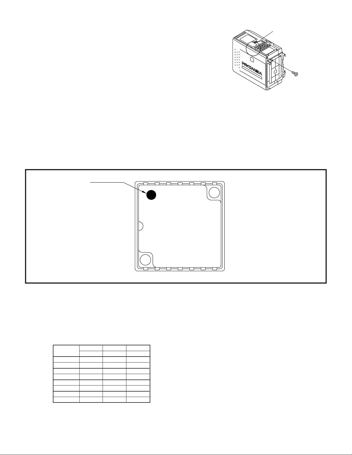
4-2. Disassembly of the VCR main body
1. Removal of the VCR lid shaft
(1)Remove one screw ((j)LX-HZ0063TAFC).
(j)
4-3. REPLACEMENT OF CCD SENSOR
4-3-1. BEFORE REPLACEMENT
1) The CCD image sensor is more sensitive to electrostatic breakage than C-MOS LSI. Therefore sufficient means to
prevent electrostatic damage must be taken when it is replaced.
• Ground the soldering iron.
• Ground also the human body, using the wrist strap(through an 1 Mohm resistor).
• Until the CCDsensor is mounted on the PWB, fit it to the conductive sponge, and short-circuit the foot lead.
2) Take utmost care so that the surface glass of CCD sensor and optical filter are not contaminated and damaged. If any
contamination is found, for example fingerprint, wipe it off with silicon paper or clean chamois skin.
3) When replacing the CCD sensor, use the antistaic grounded soldring iron, and perform quickly soldering.
Index Mark
17
JAPAN
SHARP
LZ2413H5
YYWWXXX
14 8
4-4. INITIAL SETTING OF E2PROM IC
4-4-2. IC702 (E2PROM)
When the IC702 has been replaced, make the following settings and adjustments.
1. Remove the backup battery (CR2025)
2. Turn power switch to CAMERA
3. Setting up the V ADJ mode as follows.
* After press the CONTINUE key, press the VCR ADJ key on service remote control (RRMCG0033TASA).
address data data data
03 F8 FA FE
0B 07 05 01
01 00 00 00
09 FF FF FF
04 00 00 00
0C FF FF FF
02 01 01 07
0A FE FE F8
E780U E785U E785T
3
Page 4
VL-E780U
500±20mVp-p
VL-E785U
VL-E785T
5. MECHANISM ADJUSTMENT
5-2. Items and timings of inspection and maintenance
5-2-1. Inspection and maintenance list
Checking/Maintenance point
Tape travel system
Tape travelling route
(Refer to Section)
Drum (Refer to Section)
Video head
Timing belt
Pinch roller
Capstan D.D. motor
Driving system
Relay Pulle shaft
Pulle gear shaft
Drive gear shaft
Loading motor
Performance check
Abnormal sound
PB/VS-REW take-up torque
PB/VS-REW back tension
torque
Tu brake
HC (Head Cleaner)
Oil:
Grease: MORYCOAT YM-103/X5-6020
Screw locking agent: THERE BOND 1401B
Cleaning liquid: Industrial-use ethyl alcohol
Usage time (hrs.)
500 1,000 1,500 2,000 3,000
★★★
∆∆∆
∆∆∆
★★★
★★★★★
★★★
★★★
★★★
: Replace.
: Clean.
Possible symptom
encountered
• Lateral noise
• Unclean head
• Screen shaking
• Improper S/N ratio
• No color appears.
• Tape does not run.
• Tape slackens.
• Screen shakes.
• Abnormal sound
• Not ejectable
• The specific mode cannot be set.
∆ : Apply oil.
★ : Check.
Remarks
Rollers
• If abnormal rotation or
deflection (significant) is
found, replace the roller.
Other than rollers
• Clean the tape contacting areas. Be sure to
use the specified cleaning agent.
• Replace if failure is
found.
• Apply oil.
(Oil: )
Note:
After oil is applied to the
drive gear shaft, slightly
wipe it off with swab.
• Replace if failure (abnormal sound) is detected.
• If conformance to the
standard is not ensured,
replace part.
5-4. ADJUSTMENT OF MECHANISM TAPE TRAVEL SYSTEM
5-4-3. Adjusting the Si roller height
(2)Adjusting the Si roller
6. ADJUSTMENT OF VCR
6-1. ADJUSTMENT OF VCR SECTION
6-1-5. Y/C circuit adjustment method
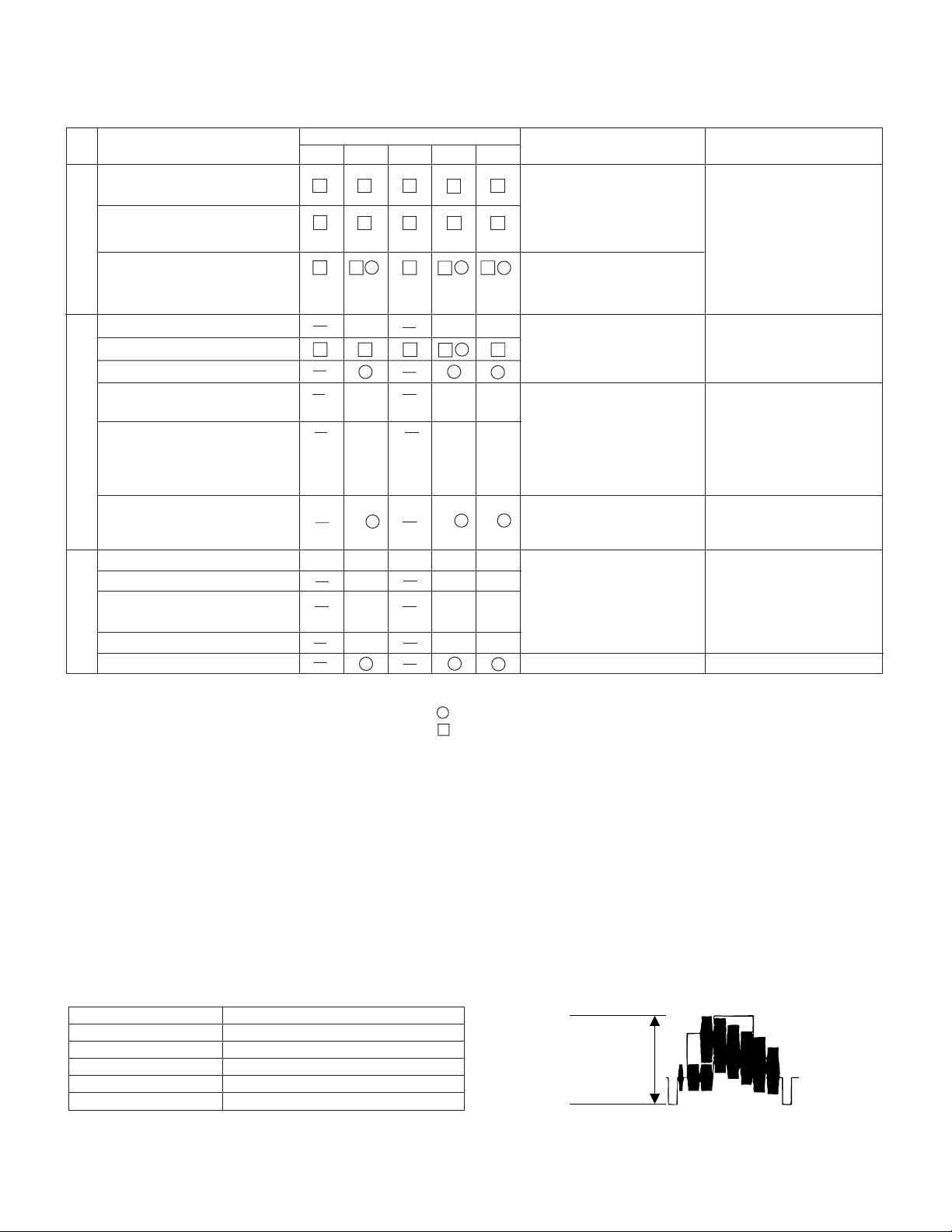
2. Adjustment of input Y level
1 Playback the tape such as to set the V/SR mode.
Measuring instrument Oscilloscope
Mode VCR STOP
Input signal Color bar
Measuring point TL801
Adjustment address 32
Adjustment level 500 Vp-p ± 20 mVp-p
4
Page 5
3. Adjustment of playback Y level
500±20mVp-p
Measuring instrument Oscilloscope
Mode PB
Playback signal Color bar (JiGWR5-5NSP)
Measuring point TL801
Adjustment address 27
Adjustment level 500 Vp-p ± 20 mVp-p
5. Adjustment of Y-FM deviation
VL-E780U
VL-E785U
VL-E785T
Measuring instrument
Oscilloscope
Mode REC/PB (self-playback/recording)
Input signal Color bar
Measuring point TL801
Adjustment address 34
Adjustment level 500 Vp-p ± 20 mVp-p
6-1-7. Adjustment of LCD display circuit
9. Inverter input voltage setting
Measuring point LCD panel display surface
Address 11, 12
Mode VCR AV input
Adjusting method Set the data of address 11 and 12.
Adjustment standard
11=C5
12=A4
Remarks ———————
6-2. ADJUSTMENT OF CAMERA SECTION
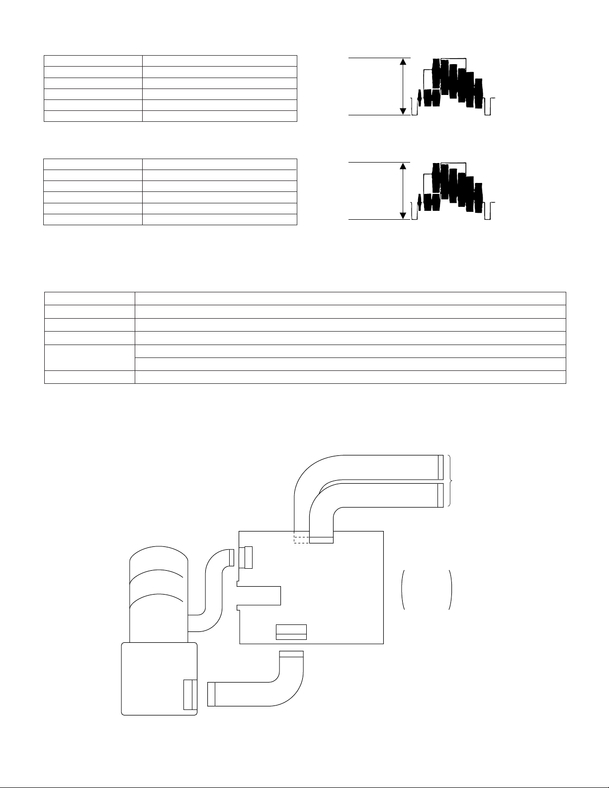
6-2-1. Servicing of camera section
• Connections for Camera Section Servicing
500±20mVp-p
LENS
CCD PWB
20pin
19pin
QPWBH2815TAZZ
SC6
20pin
SC2
SC3
19pin
QPWBH2814TAZZ
SC4
15pin
17pin
SC2 19 pin
SC3 15 pin
SC4 17 pin
SC6 20 pin
Connect FPC
between the
camera and
the VCR.
5
Page 6
VL-E780U
VL-E785U
VL-E785T
6-2-2. Adjustment procedures
6-2-2-2. Auto focus adjustment
Measuring instrument
None
Subject —
Tape —
Test point None
Adjustment address 1FF
Adjustment level 09, 0A, 0B
` Preparation for 6-2-2-3~6-2-2-9, setup the camera signal adjustment mode. (Write 00 to the address 1FE.)
6-2-2-3.
Before starting these adjustments, set up the auto focus adjust.
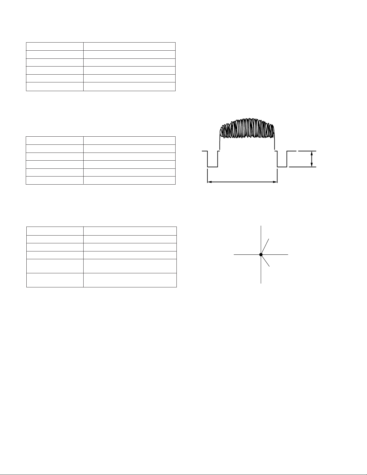
• Sync level adjustment
Measuring instrument
Oscilloscope
Video
Subject Anything
Tape —
Test point
VIDEO OUT (Terminated in 75Ω)
Adjustment address 1F8
Adjustment level 286mVp-p
1H
1) Connect the oscilloscope to the VIDEO-OUT. Adjust the sync level to 286mVp-p.
6-2-2-9.
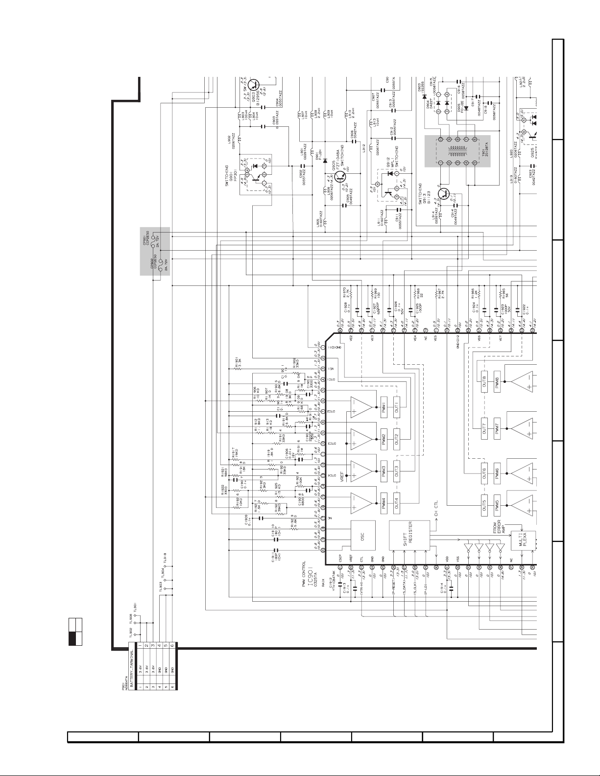
• Auto white balance adjustment
Measuring instrument
Vector scope
Subject Gray scale
Tape —
Test point
VIDEO OUT (Terminated in 75 Ω)
Adjustment address R-OUT DOOR 016
B-OUT DOOR 018
Adjustment level R-OUT DOOR; 0 ± 3 %
B-OUT DOOR; 0 ± 3 %
1) Attach the color temperature conversion filter (JIGHOYA-LB165) to the front of the lens.
2) Using the addresses R-OUT DOOR 016 and B-OUT DOOR 018, adjust the spot to the center.
3) Take off the color temperature conversion filter.
` Write FF to the address 1FE to exit from the camera signal adjustment mode.
R-Y
Spot
B-Y
Center point
SYNC
286mVp-p
6
Page 7

- M E M O -
VL-E780U
VL-E785U
VL-E785T
7
Page 8
VL-E780U
G
H
I
J
K
L
M
1
234 5 6
7
å
å
VL-E785U
VL-E785T
H
G
F
8. SCHEMA TIC DIAGRAMS
8-2. POWER CIRCUIT SCHEMATIC DIAGRAM
E
D
C
B
13
24
A
LOCATION MAP: (1/4)
1234567
8
Page 9
A
B
C
D
E
F
G
1
234 5 6
7
å
AND SHADED COMPONENTS=SAFETY RELATED PARTS
VL-E780U
VL-E785U
VL-E785T
13
24
LOCATION MAP: (2/4)
78910111213
9
Page 10
VL-E780U
G
H
I
J
K
L
M
7
8 9 10 11 12
13
VL-E785U
VL-E785T
H
G
F
E
D
C
B
13
24
A
LOCATION MAP: (3/4)
1234567
10
Page 11
A
B
C
D
E
F
G
7
8 9 10 11 12
13
VL-E780U
VL-E785U
VL-E785T
13
24
LOCATION MAP: (4/4)
78910111213
11
Page 12

VL-E780U
VL-E785U
VL-E785T
H
G
F
8-3. AUDIO CIRCUIT SCHEMATIC DIAGRAM
E
D
C
B
A
1234567
12
Page 13

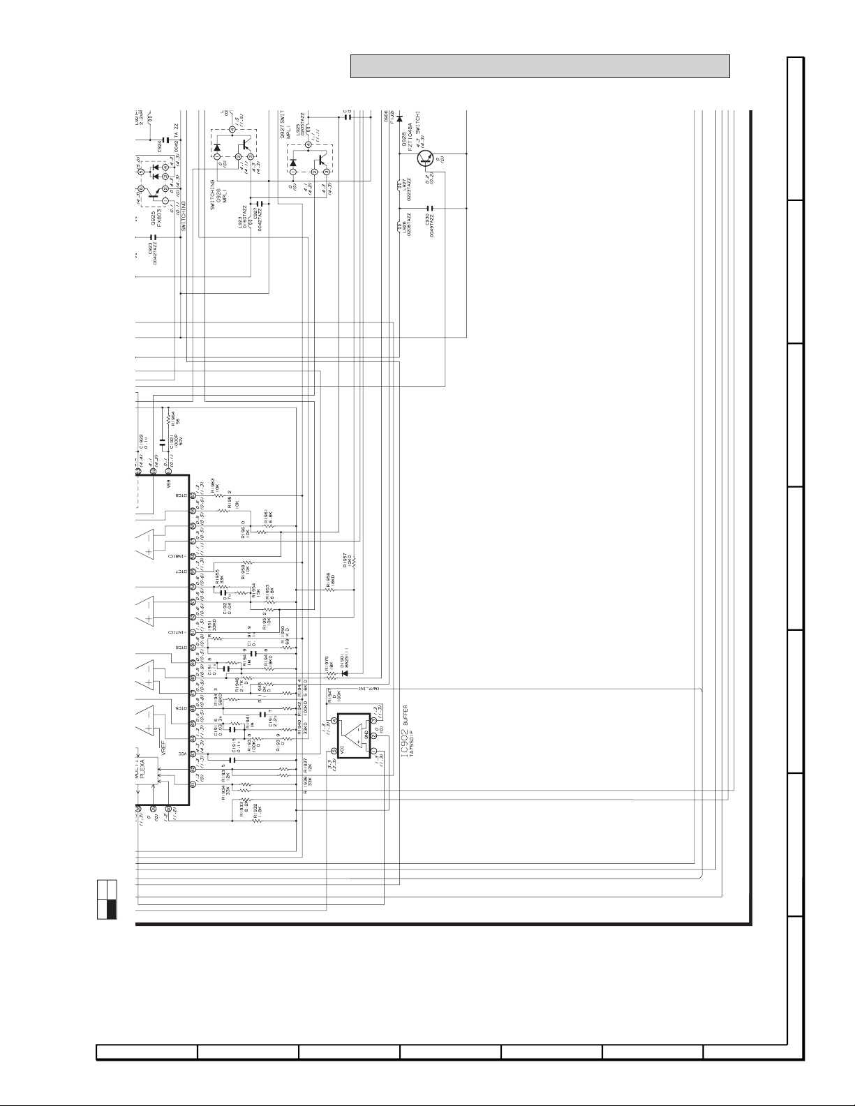
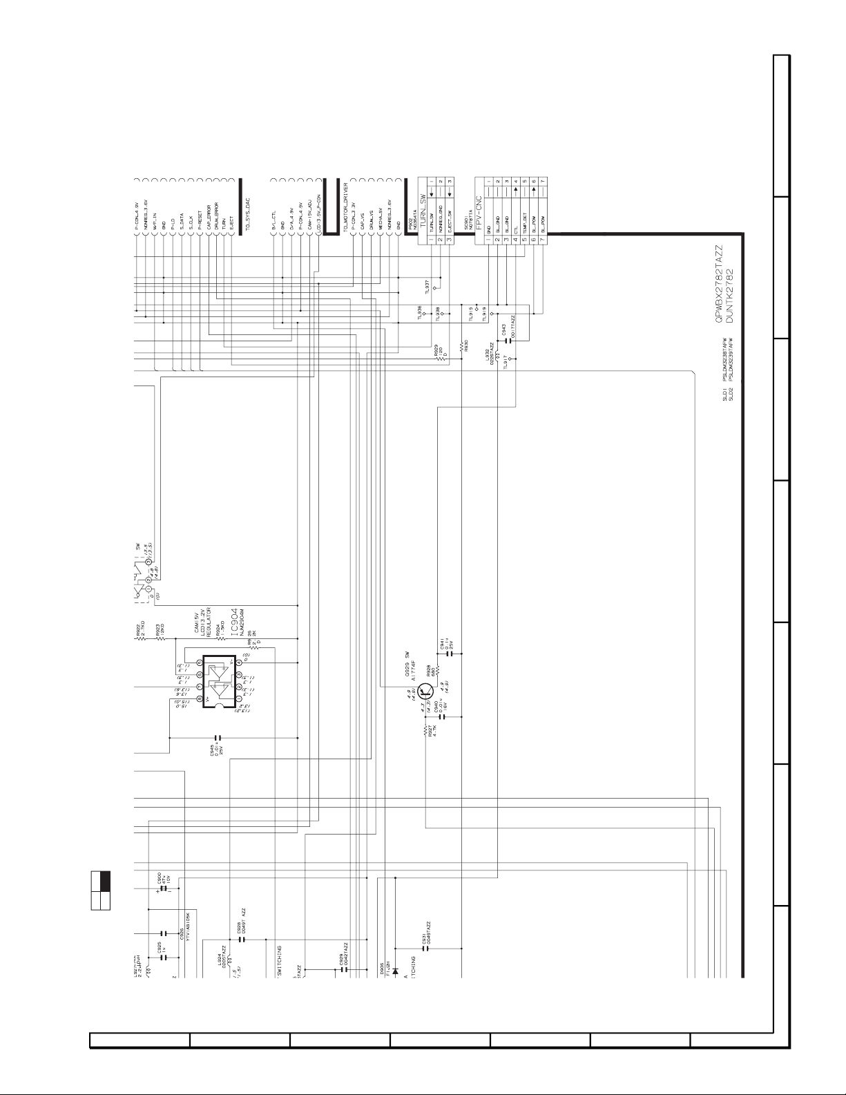
8-4. MOTOR DRIVER SCHEMATIC DIAGRAM
H
G
F
VL-E780U
VL-E785U
VL-E785T
E
D
C
B
A
1234567
78910111213
13
Page 14

VL-E780U
G
H
I
J
K
L
M
1
234 5 6
7
VL-E785U
VL-E785T
H
G
F
8-5. LCD DISPLAY CIRCUIT SCHEMATIC DIAGRAM
E
* See (S38N2VL-E710U) Page 8-21 When replacing the IC800
D
C
B
13
24
A
LOCATION MAP: (1/4)
1234567
14
Page 15

VL-E780U
A
B
C
D
E
F
G
1
234 5 6
7
VL-E785U
VL-E785T
13
24
LOCATION MAP: (2/4)
78910111213
15
Page 16

VL-E780U
G
H
I
J
K
L
M
7
8 9 10 11 12
13
VL-E785U
VL-E785T
H
G
F
E
D
C
B
13
24
A
LOCATION MAP: (3/4)
1234567
16
Page 17

A
B
C
D
E
F
G
7
8 9 10 11 12
13
VL-E780U
VL-E785U
VL-E785T
13
24
LOCATION MAP: (4/4)
78910111213
17
Page 18

VL-E780U
VL-E785U
VL-E785T
H
G
F
8-6. RF CIRCUIT SCHEMATIC DIAGRAM
E
D
C
B
A
1234567
18
Page 19

VL-E780U
VL-E785U
VL-E785T
78910111213
19
Page 20

VL-E780U
G
H
I
J
K
L
M
1
234 5 6
7
VL-E785U
VL-E785T
H
G
F
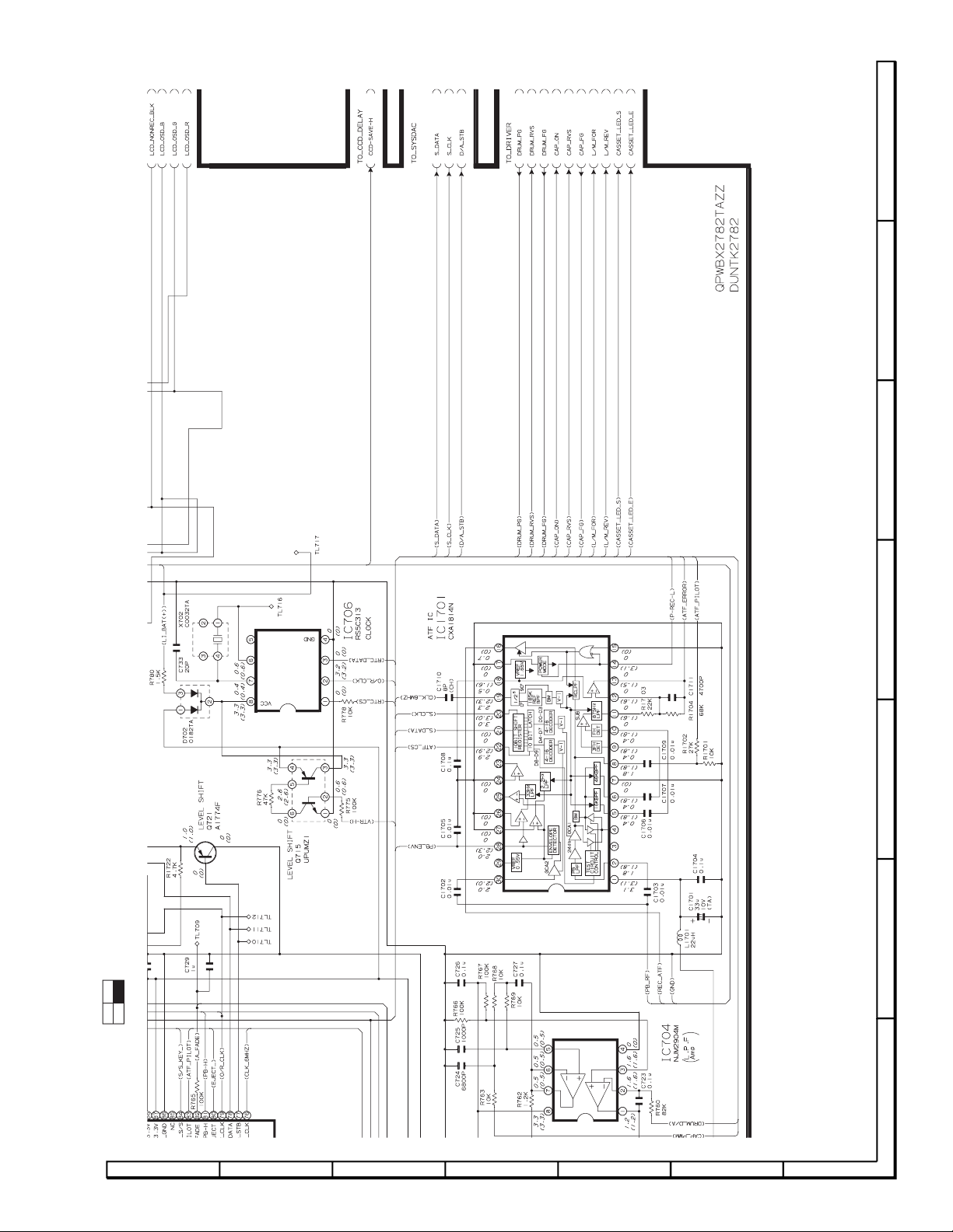
8-7. SYSTEM CONTROL CIRCUIT SCHEMATIC DIAGRAM
E
* See (S38N2VL-E710U) Page 8-22 When replacing the IC703,705
D
C
B
13
24
A
LOCATION MAP: (1/4)
1234567
20
Page 21

VL-E780U
A
B
C
D
E
F
G
1
234 5 6
7
VL-E785U
VL-E785T
13
24
LOCATION MAP: (2/4)
78910111213
21
Page 22

VL-E780U
G
H
I
J
K
L
M
7
8 9 10 11 12
13
VL-E785U
VL-E785T
H
G
F
E
D
C
B
13
24
A
LOCATION MAP: (3/4)
1234567
22
Page 23
A
B
C
D
E
F
G
7
8 9 10 11 12
13
VL-E780U
VL-E785U
VL-E785T
13
24
LOCATION MAP: (4/4)
78910111213
23
Page 24

VL-E780U
G
H
I
J
K
L
M
1
234 5 6
7
VL-E785U
VL-E785T
H
G
F
8-9. Y/C CIRCUIT SCHEMATIC DIAGRAM
E
* See (S38N2VL-E710U) Page 8-21 When replacing the IC401
D
C
B
13
24
A
LOCATION MAP: (1/4)
1234567
24
Page 25

VL-E780U
A
B
C
D
E
F
G
1
234 5 6
7
VL-E785U
VL-E785T
13
24
LOCATION MAP: (2/4)
78910111213
25
Page 26

VL-E780U
G
H
I
J
K
L
M
7
8 9 10 11 12
13
VL-E785U
VL-E785T
H
G
F
E
D
C
B
13
24
A
LOCATION MAP: (3/4)
1234567
26
Page 27

A
B
C
D
E
F
G
7
8 9 10 11 12
13
VL-E780U
VL-E785U
VL-E785T
13
24
LOCATION MAP: (4/4)
78910111213
27
Page 28

VL-E780U
VL-E785U
VL-E785T
H
G
F
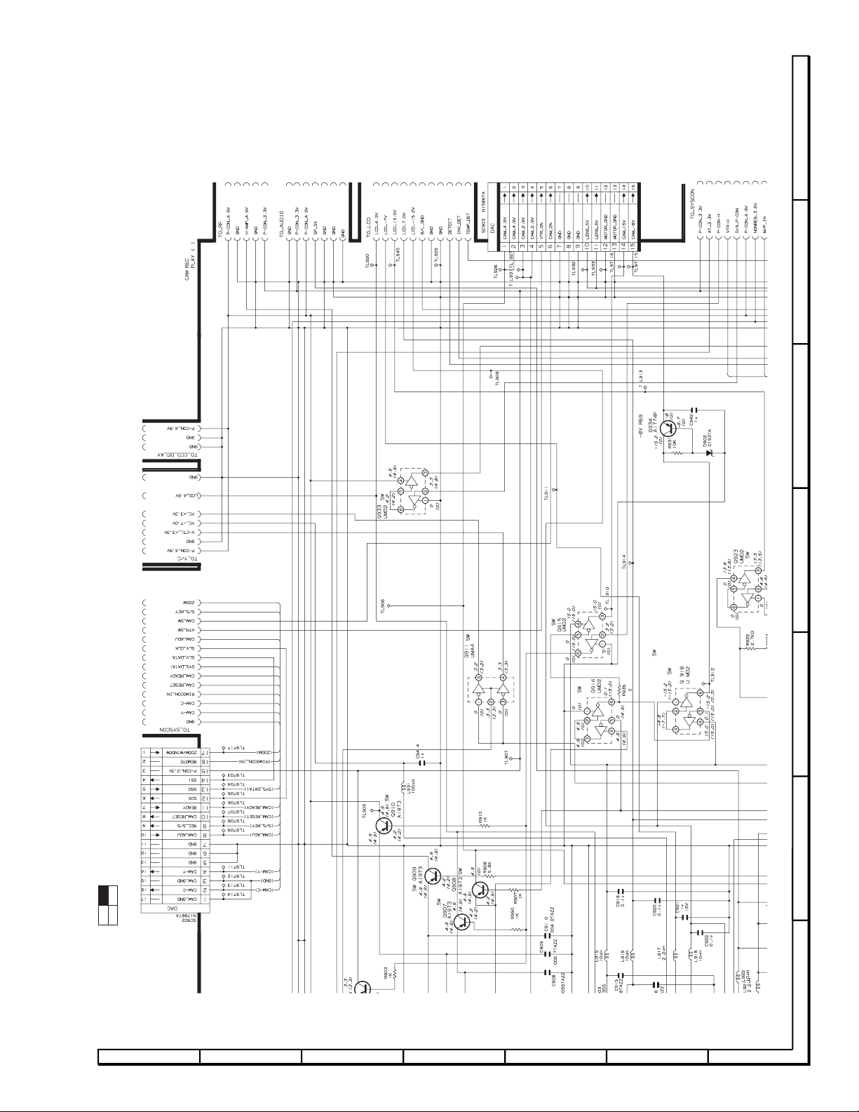
8-10. D/A CIRCUIT SCHEMATIC DIAGRAM
E
D
C
B
A
1234567
28
Page 29

Ref. No. Part No. ★ Description Code Ref. No. Part No. ★ Description Code
11.REPLACEMENT PARTS LIST/
EXPLODED VIEWS
ELECTRICAL PARTS LIST
Parts marked with
set. Be sure to replace these parts with specified ones for maintaining
the safety and performance of the set.
Les pièces marquéss
de l'appareil. Ne remplacer ces pieces que par des pièces dont le
numéro est spécifié pour maintenir la sécurité et protéger le bon
fonctinnement de l'appareil.
"
HOW TO ORDER REPLACEMENT PARTS
in USA: Contact your nearest SHARP Parts Distributor. For
★MARK : SPARE PARTS-DELIVERY SECTION:ALL JAPAN
in CANADA: Contact SHARP Electronics of Canada Limited
To have your order filled promptly and correctly, please furnish
the following informations.
"å"
are important for maintaining the safety of the
"å"
sont importantes pour maintenir la sècurité
location of SHARP Parts Distributor,
Call Toll-free 1-IBE800-SHARP
Phone (416) 890-2100.
1. MODEL NUMBER 2. REF. NO.
3. PART NO. 4. DESCRIPTION
5. PRICE CODE
"
VL-E780U
VL-E785U
VL-E785T
å MARK: SAFETY RELATED PARTS
å PIECES: RELATIVES A LA SECURITE
PWB ASSEMBLY IS NOT REPLACEMENT ITEM
L'ASSEMBLANGE P.C.I. EST UN ARTICLE NON REMPLACABLE
Ref. No. Part No. ★ Description Code
PRINTED WIRING BOARD ASSEMBLIES
(NOT REPLACEMENT ITEM)
DUNTK2782QA10 J VCR Unit(VL-E780U) —
DUNTK2782QA11 J VCR Unit(VL-E785U) —
DUNTK2782QA17 J VCR Unit(VL-E785T) —
DUNTK2785QA01 J CAMERA Unit —
DUNTK2782QA10 VCR UNIT(VL-E780U)
DUNTK2782QA11 VCR UNIT(VL-E785U)
DUNTK2782QA17 VCR UNIT(VL-E785T)
IC703 RH-iX0609TAZZ J CXP87460-126R(VL-E785T)AY
IC705 RH-iX0612TAZZ J IX0612TA(VL-E785T) AR
Q415 VS2PA1774R/-1 J Transistor AB
Q602 VSRT1N441U/-1 J Transistor AB
R447 VRS-CZ1JF122J J 1.2k 1/16W Metal Oxide AA
R454 VRS-CZ1JF102D J 1k 1/16W Metal Oxide AA
R455 VRS-CZ1JF102D J 1k 1/16W Metal Oxide AA
R826 VRS-CZ1JF124D J 120k 1/16W Metal Oxide AA
R950 VRS-CZ1JF102J J 1k 1/16W Metal Oxide AA
R1820 VRS-CZ1JF393J J 39k 1/16W Metal Oxide AA
R1821 VRS-CZ1JF393J J 39k 1/16W Metal Oxide AA
INTEGRATED CIRCUITS
TRANSISTORS
RESISTORS
DUNTK2785QA01 CAMERA UNIT
RESISTORS
R536 VRS-CZ1JF153J J 15k 1/16W Metal Oxide AA
R576 VRS-CZ1JF393J J 39k 1/16W Metal Oxide AA
R582 VRS-CZ1JF334D J 330k 1/16W Metal Oxide AA
Note
:
In this chapter, only the differences from VL-E760U/765U
are described. Therefore, for the parts which are not
described in this page, refer to the Service Manual for VLE760U/765U (S38N2VL-E760U) chapter 11.
29
Page 30

VL-E780U
VL-E785U
VL-E785T
Ref. No. Part No. ★ Description Code Ref. No. Part No. ★ Description Code
MECHANISM CHASSIS EXPLODED VIEW
315
214
312
354
345
375
352
202
200
204
209
214
317
303
301
362
356
319
209
211
209
314
368
209
332
214
333
213
318
325
215
316
302
359
326
324
328
311
304
209
370
364
349
200
204
202
310
209
322
323
214
203
351
H
351
G
208
367
F
E
208
365
376
341
366
208
D
212
330
343
214
339
209
209
354
355
305
214
362
306
209
307
337
346
201
369
348
208
205
202
208
353
350
204
208
313
363
327
308
309
321
C
331
357
216
207
344
206
336
B
329
A
209
342
209
340
338
206
358
216
209
209
374
372
209
334
209
214
335
214
361
360
214
300
123456
30
Page 31

VL-E780U
VL-E785U
VL-E785T
Ref. No. Part No. ★ Description Code Ref. No. Part No. ★ Description Code
MECHANISM PARTS
300 LCHSM0163GEZZ J Main Chassis Ass'y AW
301 NGERH1280GEZZ J Main Cam AD
302 NGERH1281GEZZ J Sub-Cam AD
303 MLEVF0470GEFW J Eject Lever AD
304 MLEVF0492GEFW J M Function Lever AF
305 LHLDZ1966GEZZ J L Block Holder AD
306 NGERW1064GEZZJ Worm Pulley AC
307 NGERW1065GEZZJ Worm AD
308 NGERH1282GEZZ J Worm Wheel AC
309 NGERH1283GEZZ J Lo Relay Gear AC
310 MARMM0126GEZZJ S Lo Arm Ass'y AE
311 MARMM0128GEZZJ T Lo Arm Ass'y AF
312 LANGA0069GEFW J S Lo Arm Retainer AD
313 PGiDM0146GEZZ J Sup Rail AD
314 PGiDM0171GEZZ J Tu Rail AD
315 NGERH1284GEZZ J Sup Lo Gear AC
316 NGERH1285GEZZ J Tu Lo Gear AC
317 MSPRD0167GEZZ J S Lo Arm Double-Acting AE
Spring
318 MSPRT0407GEZZ J T Lo Arm Double-Acting AC
Spring
319 MLEVP0310GEZZ J HC Lever Ass'y AF
321 MSLiF0074GEFW J Ten Arm Operation Lever AD
322 PGiDM0148GEZZ J Ten Arm Guide AC
323 NGERH3045GEFWJ Segment Gear AD
324 MLEVF0472GEZZ J Tu Guide Ass'y AC
325 PGiDP0027GEZZ J Tu Guide AE
326 MSPRC0183GEZZ J Tu Guide Spring AA
327 MSPRC0184GEZZ J Si Roller Spring AA
328 MSPRC0208GEZZ J Tu Guide Lever Spring AC
329 LCHSS0049GEZZ J Slide Chassis Ass'y AP
330 MLEVF0495GEZZ J Ten Arm Ass'y AC
331 LBNDK3023GEZZ J Ten Band Ass'y AF
332 NiDR-0016GEZZ J Swing Gear Ass'y AF
333 NGERH1286GEZZ J Driving Gear AC
334 NGERH1287GEZZ J Pulley Gear AD
335 NPLYV0157GEZZ J Relay Pulley AD
336 MLEVP0284GEZZ J S Brake AC
337 NGERH1288GEZZ J Tu Brake Gear AC
338 MLEVP0285GEZZ J Tu Main Brake AC
339 MLEVP0286GEZZ J Tu Sub-Brake AC
340 MSPRD0169GEZZ J Tu Brake Spring AD
341 LHLDZ2053GEZZ J Light Guide Holder Ass'y AF
342 LANGG9102GEFWJ Down Guide AF
343 MSPRT0408GEZZ J Tension Spring AD
344 MSPRD0170GEZZ J S Brake Spring AD
345 CDRMU0032GE01 J Upper Drum Ass'y BF
346 PGiDM0154GEZZ J Tape Guide AB
348 QBRSK0039GEZZ J Earth Spring AD
349 PGiDM0143GEZZ J Drum Base AG
350 DDRML0020HE01 J Lower Drum Ass'y AY
351 RMOTP1137GEZZ J Drum Motor AS
352 PSPAQ0010GEZZ J Gap Adjusting Shim AC
353 NRTR-0096GEZZ J R Tr Rotor Ass'y AP
354 MSPRC0209GEZZ J Gr Adjusting Spring AC
355 LPOLM0058GEZZ J S Pole Base AK
356 LPOLM0059GEZZ J T Pole Base AK
357 NDAiV1071GEZZ J Sup Reel Support AG
358 NDAiV1072GEZZ J Tu Reel Support AG
359 MLEVF0517GEZZ J Pinch Lever Ass'y AS
360 NBLTT0012GEZZ J Timing Belt S AE
361 NBLTT0013GEZZ J Timing Belt L AE
362 NROLP0108GEZZ J Guide Roller Ass'y AG
363 NROLP0109GEZZ J Si Roller Ass'y AH
364 QPWBH5428GEZZJ Mode FPC AG
365 CPWBN5402GE01 J Sensor Ass'y BC
366 QSW-M0042GEZZ J Recognition SW AH
367 RDTCH0037GEZZ J Dew Sensor AF
368 RMOTV1019GEZZ J Cap. Motor AZ
369 RMOTM1075GEZZJ Load. Motor AL
370 QSW-R0038GEZZ J Mode SW AG
372 RAMP-0017TAN0 J H/A PWB AY
374 TLABH0196TAZZ J Caution Label AB
375 PSHEM0014GEZZ J Counter Balance AC
376 PSHEP0013GEZZ J Interruption Sheet AC
200 XAPSF17P03200 J Screw M1.7x3.2 AA
201 LX-XZ3036GEFP J Screw M2.0x6.0 AD
202 LX-BZ3175GEFN J Screw M1.7x4.0 AC
203 LX-BZ3163GEFN J Screw M1.7x2.5 AC
204 LX-HZ3074GEFN J Screw M1.7x5.3 S Tight AA
205 LX-BZ3177GEFF J Screw M1.4x1.5 AB
206 LX-BZ3132GEFF J Screw M1.4x1.5xD3.5 AA
207 LX-BZ3178GEZZ J Screw M1.4x1.5xD4.0 AD
208 LX-HZ3083GEFF J Screw M1.4x2.5 S Tight AB
209 LX-HZ3077GEFN J Screw M1.4x3.0 S Tight AA
211 LX-HZ3084GEFF J Screw M1.4x4.0 S Tight AC
212 LX-HZ3116GEFD J Screw M1.4x3.2 S Tight AB
213 LX-NZ3053GEZZ J Screw M1.4 Nut AC
214 LX-WZ1076GE02 J Washer D0.8xD3.0x0.2t AA
215 LX-WZ1075GE02 J Washer D2.1xD5.0x0.25t AA
216 XWHJZ12-02040 J Washer D1.2xD4.0x0.25t AC
Plastics
Plastics
Plastics
—— End of Mechanism Parts ——
OTHER PARTS
SUPPLIED ACCESSORIES
RRMCG0072TASA J Infrared Remote Control AP
RRMCG0073TASA J Infrared Remote Control
TiNSE0313TAZZ J Operation Manual AG
TiNSE0314TAZZ J Operation Manual AH
TiNS-6013TAZZ J Operation Manual
UBATM0010TAZZ J Battery (VL-E780U/785U) BC
UBATM0011TAZZ J Battery (VL-E785T) BC
UADP-0274TAZZ J AC Adapter —
UADP-0275TAZZ J AC Adapter (VL-E785T) —
ACCESSORIES
UBATL0011TAZZ J Lithium Battery —
UBATU0023GEZZ J AA Drycell Battery —
(NOT REPLACEMENT ITEM)
PACKING PARTS
SPAKC7399TAZZ – Packing Case(VL-E780U) —
SPAKC7403TAZZ – Packing Case(VL-E785U) —
SPAKC7404TAZZ – Packing Case(VL-E785T) —
SPAKP6049TAZZ – Wrapping Paper —
SSAKA0087TAZZ – Polyethylene Bag —
(VL-E780U/785U)
(VL-E785T)
(VL-E780U)
(VL-E785U)
(VL-E785T)
(VL-E780U/785U)
(NOT REPLACEMENT ITEM)
31
Page 32

VL-E780U
VL-E785U
VL-E785T
Ref. No. Part No. ★ Description Code Ref. No. Part No. ★ Description Code
CABINET EXPLODED VIEW
54
34
37
38
43
b
1
b
45
46
12
11
9
10
9
10
8
b
15
2-2
2-3
5-4
5
5-2
c
5-5
5-3
5-6
48
e
1-2
e
50
18
21
51
13
49
a
3-2
j
H
3
a
a
G
26
27
30
c
b
28
29
F
31
b
33
4-2
a
4
a
39
47
c
49
32
d
d
16
17
E
6
6-16
b
d
D
C
6-3
6-2
6-10
6-5
6-6
d
6-7
7
7-2
6-15
6-4
h
h
b
25
c
g
6-14
6-12
6-9
6-9
6-8
b
b
53
b
6-13
b
6-11
20
35
36
c
c
41
40
b
42
44
1-3
e
1-4
52
b
56
14
a
B
b
b
b
b
7-4
7-3
d
7-5
A
f
d
22
23
f
f
24
2-4
2-5
2
123456
32
Page 33

VL-E780U
VL-E785U
VL-E785T
Ref. No. Part No. ★ Description Code Ref. No. Part No. ★ Description Code
CABINET PARTS LIST
1 DCABA6183TAK3 J V Frame Service AL
(VL-E780U)
1 DCABA6183TAK1 J V Frame Service AL
(VL-E785U)
1 DCABA6183TAK2 J V Frame Service AL
(VL-E785T)
1-2 PSPAG0095TAZZ J VCR Lid Cushion AA
1-3 TLABH0355TAZZ J Lithium Exchange Label AB
(VL-E780U/785U)
1-3 TLABH0259TAZZ J Lithium Exchange Label AD
(VL-E785T)
1-4 LHLDB1027TAZZ J Lithium Holder AD
2 DCABB6184TAK3 J L Cabinet Service AS
(VL-E780U/785U)
2 DCABB6184TAK4 J L Cabinet Service
(VL-E785T)
2-2 QEARP0234TAFJ J LCD Earth Sheet AE
2-3 TLABH0318TAZZ J Facing Recording Caution AB
Label (VL-E780U/785U)
2-3 TLABH0326TAZZ J Facing Recording Caution AB
Label (VL-E785T)
2-4 GCOVH1226TASA J Jack Cover AD
2-5 GCOVA1535TAZZ J Remote Control Receptor AD
Cover
3 CCABC6091TAK4 J Camera Front Cabinet AT
Ass’y
3-2 GCOVA1539TASB J Lens Hood AK
4 DCABD6088TAK4 J Camera Rear Cabinet AS
Ass’y (VL-E780U/785U)
4 DCABD6094TAK2 J Camera Rear Cabinet
Ass’y (VL-E785T)
4-2 JBTN-0276TASB J Camera Button AF
5 DFTAC1277TAK1 J VCR Lid Service AU
(VL-E780U)
5 DFTAC1278TAK1 J VCR Lid Service AU
(VL-E785U/T)
5-2 HBDGS0059TASB J LCD Badge AE
5-3 LANGK0428TAFW J VCR Lid Reinforcing Angle AG
5-4 LANGK0400TAFW J Eject Fitting AD
5-5 PSPAZ0193TAZZ J VCR Lid Sheet AC
5-6 MSPRD0047TAFJ J VCR Lid Spring AD
6 CCOVA1536TAK5 J KS Side Cover AU
(VL-E780U/785U)
6 CCOVA1536TAK8 J KS Side Cover AT
(VL-E785T)
6-2 NSFTZ0049TAFW J Battery Lid Axle AC
6-3 MSPRD0050TAFJ J Battery Lid Spring AC
6-4 TLABH0264TAZZ J Recycle Label AB
6-5 GFTAB1066TAKA J Battery Lid AE
6-6 HDECP0045TASA J Battery Decoration Plate AC
6-7 LHLDZ1448TA00 J Battery Intermediate Lock AC
6-8 MSPRC0103TAFJ J Battery Intermediate Lock AD
Spring
6-9 MSPRC0102TAFJ J Battery Lock Lever Spring AA
6-10 MLEVP0030TASA J Battery Lid Open/Close AC
Lever
6-11 LHLDZ1449TAZZ J Battery Lock Holder AC
6-12 MLEVP0029TASA J Battery Lock Lever AC
6-13 MSPRC0101TAFJ J Battery Push-out Spring AD
6-14 LHLDZ1445TAZZ J Lens Holder AD
6-15 LANGK0398TA00 J Battery Lid Angle Fitting AH
6-16 UBNDT0122TAZZ J Hand Strap
7 DCOVA1538TAK1 J Tilt Ass’y AU
7-2 PSPAZ0190TAZZ J Tilt Spacer AE
7-3 GCOVA1537TAKA J Tilt Frame V AL
7-4 PSPAZ0189TAZZ J Rotation Spacer AD
7-5 LANGH0071TAFW J Stopper Fitting AD
8 LHLDZ1447TAZZ J LCD Holder AG
9 PSHEP0048TAZZ J Diffusion Sheet AE
10 PSHEP0047TAZZ J Prism Sheet AH
11 PGiDM0026TAZZ J Light Guide Plate AH
12 PMiR-0022TAZZ J Reflection Sheet AD
å 13 CLMPV0045TA01 J Lamp Inverter Unit
14 CPNLC0030RM02 J LCD Panel CE
15 PZETV0370TAZZ J LCD Glass Retaining AB
16 TLABM1930TAZZ J Model Label(VL-E780U) AC
16 TLABM1934TAZZ J Model Label(VL-E785U) AC
16 TLABM1935TAZZ J Model Label AD
(VL-E785T)
16 TLABG0118TAZZ J Tax Paying Label AC
(VL-E785T)
17 TLABN0174TAZZ J Serial No. Label(VL-E780U)AC
17 TLABN0175TAZZ J Serial No. Label AC
(VL-E785U)
18 CLNSA0127TA01 J Lens Unit BS
19 GFTAC1241TASA J Cassette Compartment AD
Cover
20 DUNTK2782QA10 J VCR Unit(VL-E780U) —
20 DUNTK2782QA11 J VCR Unit(VL-E785U) —
20 DUNTK2782QA17 J VCR Unit(VL-E785T) —
21 DUNTK2785QA01 J Camera Unit —
22 QPWBH2814TAZZ J Tilt FPC AQ
23 LHLDW1038TA00 J FPC Holder AC
24 QSW-Z0287TAZZ J VCR Operation Unit AW
(VL-E780U/785U)
24 QSW-Z0301TAZZ J VCR Operation Unit AV
(VL-E785T)
25 QTANZ0129TAZZ J Battery Terminal Unit AG
26 QSW-Z0285TAZZ J Power Unit AR
27 LHLDZ1452TAZZ J Power Lock Holder AC
28 MSPRC0083TAFJ J Power Lock Spring AA
29 JBTN-0277TASB J Power Button AF
30 LHLDZ1451TAZZ J Power Holder AC
31 JKNBP0152TASA J Power Knob AD
32 JKNBP0153TASB J Zoom Knob AF
33 LHLDZ1453TASA J Zoom Knob Holder AD
34 JKNBP0154TASA J Open Knob AC
35 PSPAZ0191TAZZ J Spacer AA
36 RMiCC0079TAZZ J Microphone AM
37 MSPRT0034TAFJ J Lid Lock Spring AC
38 LHLDZ1454TA00 J VCR Lid Lock AD
39 NSFTZ0084TAFW J VCR Lid Shaft AD
40 PSPAZ0192TAZZ J Microphone Lead Spacer AD
41 LHLDZ1450TAZZ J Speaker Holder AC
42 VSP0020P-94WN J Speaker AL
43 PSPAG0103TAZZ J Speaker Spacer AC
44 PCOVP9062TAZZ J Speaker Mesh AB
45 PSPAG0095TAZZ J VCR Lid Cushion AA
46 GCOVA3056TAKA J Speaker Cover AE
47 ZTAPEZ800020E J Tape —
48 QSW-Z0284TAZZ J Turn/Eject SW AH
49 MLEVP0031TAZZ J Eject Lever AC
50 LANGK0399TAFW J Tripod Angle Ass’y AK
51 PSHEP0074TAZZ J Microphone Lead Sheet AB
52 QJAKZ0071TAZZ J Jack Unit AS
53 PSPAG0084TA00 J Front Group Frame AD
Rubber
54 GCOVA3057TAKA J Microphone Cover AG
55 QPWBH2815TAZZ J CCD FPC AS
56 PSPAZ0209TAZZ J LCD Spacer AF
a LX-HZ0018TAFN J M2x6 Tapping, Silver AA
b LX-HZ0018TAFF J M2x6 Tapping, Black AA
c LX-HZ0045TAFN J M2x4 Tapping, Silver AA
d XiPSF20P04000 J M2x4 Small Screw, Black AA
Zinc Plating
e LX-BZ0191TAFD J M2 Special Screw AC
f XiPSD20P03000 J M2x3 Screw AA
g LX-UZ0016TAFD J M2x5 Special Screw AA
h LX-BZ0200TAFD J M2x7 Special Screw AB
i XiPSN20P04000 J M2x4 Small Screw, Silver AA
j LX-HZ0063TAFC J M1.7x6 Tapping, Silver AA
—— End of Cabinet Parts ——
33
Page 34

VL-E780U
VL-E785U
VL-E785T
Ref. No. Part No. ★ Description Code Ref. No. Part No. ★ Description Code
CASSETTE HOUSING PARTS
400 CHLDX3077GE01 J Cassette Compartment AY
Assy
401 MSPRT0414GEZZ J Up Main Spring AD
402 MROD-0014GEFJ J Damper rod AG
403 PDMP-0013GEZZ J Cassette Compartment AG
Damper
—— End of Cassette Housing Parts ——
CASSETTE HOUSING CONTROL UNIT
D
403
402
400
401
C
401
B
A
123456
34
Page 35

Ref. No. Part No. ★ Description Code Ref. No. Part No. ★ Description Code
12. PACKING OF THE SET
GCOVH1225TASA
(Lens Cap)
UADP-0274TAZZ
(VL-E780U/E785U)
UADP-0275TAZZ(VL-E785T)
(AC Adapter)
QCNW-1338TA00
(DC Cable)
★UBATU0023GEZZ
(Battery (AA x 2))
VL-E780U
VL-E785U
VL-E785T
UBNDS0010TASA
(Shoulder Strap)
RRMCG0072TASA
(Remote Control)
QCNW-1448 or 1295TAZZ
(A/V Cable)
★SPAKA6176TAZZ
(Packing ADD.)
Fold
down
★SPAKA6202TAZZ
(Packing ADD.)
UBATM0010TAZZ
(VL-E780U/E785U)
UBATM0011TAZZ(VL-E785T)
(Battery)
★UBATL0011TAZZ
(Lithium Battery x 2)
Fold down
★SPAKP6049TAZZ
(Wrapping Paper)
TiNSE0313TAZZ(VL-E780U)
TiNSE0314TAZZ(VL-E785U)
TiNS-6013TAZZ(VL-E785T)
(Operation Manual)
★SPAKA6237TAZZ
(Packing ADD.)
★SPAKC7399TAZZ(VL-E780U)
★SPAKC7403TAZZ(VL-E785U)
★SPAKC7404TAZZ(VL-E785T)
(Packing Case)
★ Not Replacement Item
35
Page 36

VL-E780U
VL-E780U
VL-E785U
VL-E785U
VL-E785T
VL-E785T
Ref. No. Part No. ★ Description Code Ref. No. Part No. ★ Description Code
COPYRIGHT C 1998 BY SHARP CORPORATION
ALL RIGHTS RESERVED.
No part of this publication may be reproduced,
stored in a retrieval system, or transmitted in
any form or by any means, electronic, mechanical,
photocopying, recording, or otherwise, without
prior written permission of the publisher.
Dec. 1998 Printed in JAPAN
SA. NS
SHARP CORPORATION
AV Systems Group
Quality & Reliability Control Center
Yaita, Tochigi 329-2193, Japan
36
 Loading...