

SHARP VLAD260U Service Manual
VL-AD260U
SERVICE MANUAL
LIQUID CRYSTAL CAMCORDER
SERVICE MANUAL
S51T2VL-AD260
LIQUID CRYSTAL CAMCORDER Hi 8 NTSC
MODEL
In the interests of user-safety (Required by safety regulations in some countries) the set should be restored to its
original condition and only parts identical to those specified
be used.
VL-AD260U
Hi
8
NTSC
MODEL VL-AD260U
1. IMPORTANT SERVICE NOTES......................................................................................................... 2
2. SPECIFICATIONS .............................................................................................................................. 5
3. PART NAMES AND FUNCTION ........................................................................................................ 6
4. DISASSEMBLY OF THE SET ............................................................................................................ 7
5. MECHANISM ADJUSTMENT........................................................................................................... 13
6. ADJUSTMENT OF VCR AND CAMERA .......................................................................................... 24
7. SYSTEM BLOCK DIAGRAMS.......................................................................................................... 37
8. SCHEMATIC DIAGRAMS................................................................................................................. 46
9. PRINTED WIRING BOARD ASSEMBLIES ...................................................................................... 84
10.REPLACEMENT PARTS LIST ......................................................................................................... 97
11.PACKING OF THE SET.................................................................................................................. 114
CONTENTS
Page
SHARP CORPORATION
This document has been published to be used for
after sales service only.
The contents are subject to change without notice.
1
VL-AD260U
0.15 µF
SONDE D'ESSAI
VERS PIECES
METALLIQUES
EXPOSEES
VTVM
ECHELLE CA
1.5K OHMS
10W
CONNECTER A
UNE MASSE DE
TERRE CONNUE
1. IMPOR TANT SERVICE NOTES
BEFORE RETURNING THE VIDEO CAMERA
RECORDER
Before returning the video camera recorder to the user,
perform the following safety checks.
1. Inspect all lead dress to make certain that leads are
not pinched or that hardware is not lodged between
the chassis and other metal parts in the video camera
recorder.
2. Inspect all protective devices such as non-metallic
control knobs, insulating materials, cabinet backs,
adjustment and compartment covers or shields, isolation resistor/capacitor networks, mechanical insulators etc.
3. To be sure that no shock hazard exists, check for
leakage current in the following manner.
· Plug the AC line cord directly into a 120 volt AC outlet
(Do not use an isolation transformer for this test).
·
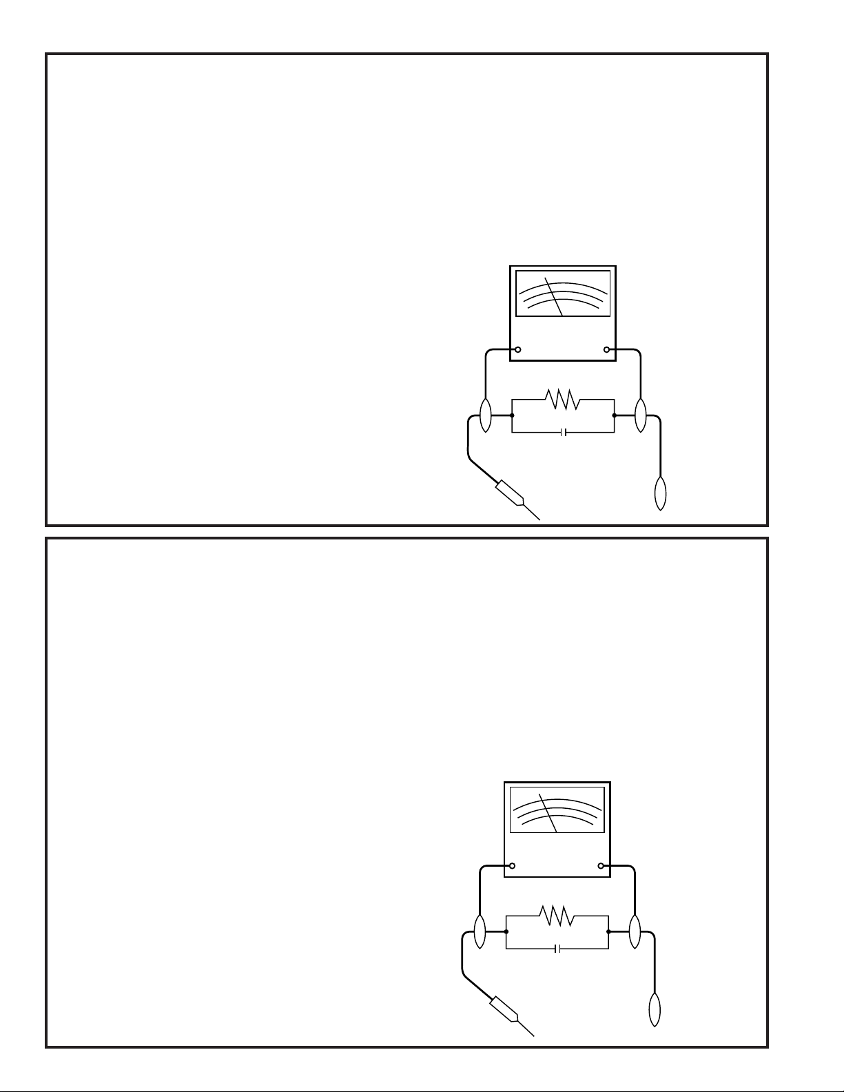
Using two clip leads, connect a l.5 k ohm, 10 watt resistor
paralleled by a 0.15 µF capacitor in series with all
exposed metal cabinet parts and a known ground,
such as a water pipe or conduit.
· Use a VTVM or VOM with 1000 ohm per volt, or higher
sensitivity or measure the AC voltage drop across the
resistor (See Diagram).
· Move the resistor connection to all exposed metal
parts having a return path to the chassis (antenna
connections, metal cabinet, screw heads, knobs and
control shafts, etc.) and measure the AC voltage drop
across the resistor. Reverse the AC plug (a non
polarized adaptor plug must be used but only for the
purpose of completing these checks) on the set and
repeat the AC voltage measurements for each exposed metallic part. Any reading of 0.45 V rms (this
corresponds to 0.3 mA rms AC.) or more is excessive
and indicates a potential shock hazard which must be
corrected before returning the video camera recorder
to the user.
VTVM
AC SCALE
1.5k ohms
10W
0.15 µF
TEST PROBE
TO EXPOSED
METAL PARTS
CONNECT TO
KNOWN EARTH
GROUND
AVANT DE RENDRE LE MAGNETOSCOPE
Avant de rendre le magnétoscope à l’utilisateur, effectuer
les vérifications de sécurité suivantes.
1. Vérifier toutes les gaines de fil pour être sûr que les fils
2. Vérifier tous les dispositifs de protection tels que les
3. Pour être sûr qu’il n’y a aucun risque de choc électrique,
· Brancher le cordon d’alimentation secteur directement
· Utiliser deux fils à pinces et connecter une résistance
· Utiliser un VTVM ou VOM avec une sensibilité de
· Déposer la connexion de la résistance à toutes les
1. NOTES DE SERVICE IMPOR TANTES
ne sont pas pincés ou que le matériel n’est pas coincé
entre le châssis et les autres pièces métalliques dans le
magnétoscope.
boutons de commande non métalliques, les matériaux
d’isolement, le dos du coffret, les couvercles de
compartiment et ajustement ou les boucliers, les
réseaux de résistance / condensateur d’isolement,
Ies isolateurs mécaniques, etc.
vérifier le courant de fuite de la maniére suivante.
dans une prise de courant de 120 volts. (Ne pas
utiliser de transformateur d’isolement pour cet essai).
de 10 watts 1,5 k ohm en parallèle avec un
condensateur de 0,15 µF en série avec des pièces du
coffret métallique exposées et une masse de terre
connue telle qu’un tuyau ou un conduit d’eau.
1000 ohms par volt ou plus ou mesurer la chute de
tension CA entre la résistance (voir diagramme).
pièces métalliques exposées ayant un parcours de
retour au châssis (connexions d’antenne, coffret
métallique, tétes de vis, boutons et arbres de commande,
etc.) et mesurer la chute de tension CA entre la résistance.
Inverser la fiche CA (une fiche intermédiaire non polarisée
doit être utilisée à seule fin de faire ces vérifications.) sur
l’appareil et répéter les mesures de tension CA pour
chaque piéce métallique exposée. Toute lecture de
0,45 V rms (ceci correspond à 0,3 mA rms CA) ou plus
est excessive et signale un danger de choc qui doit être
corrigé avant de rendre le magnétoscope à son
utilisateur.
2
VL-AD260U
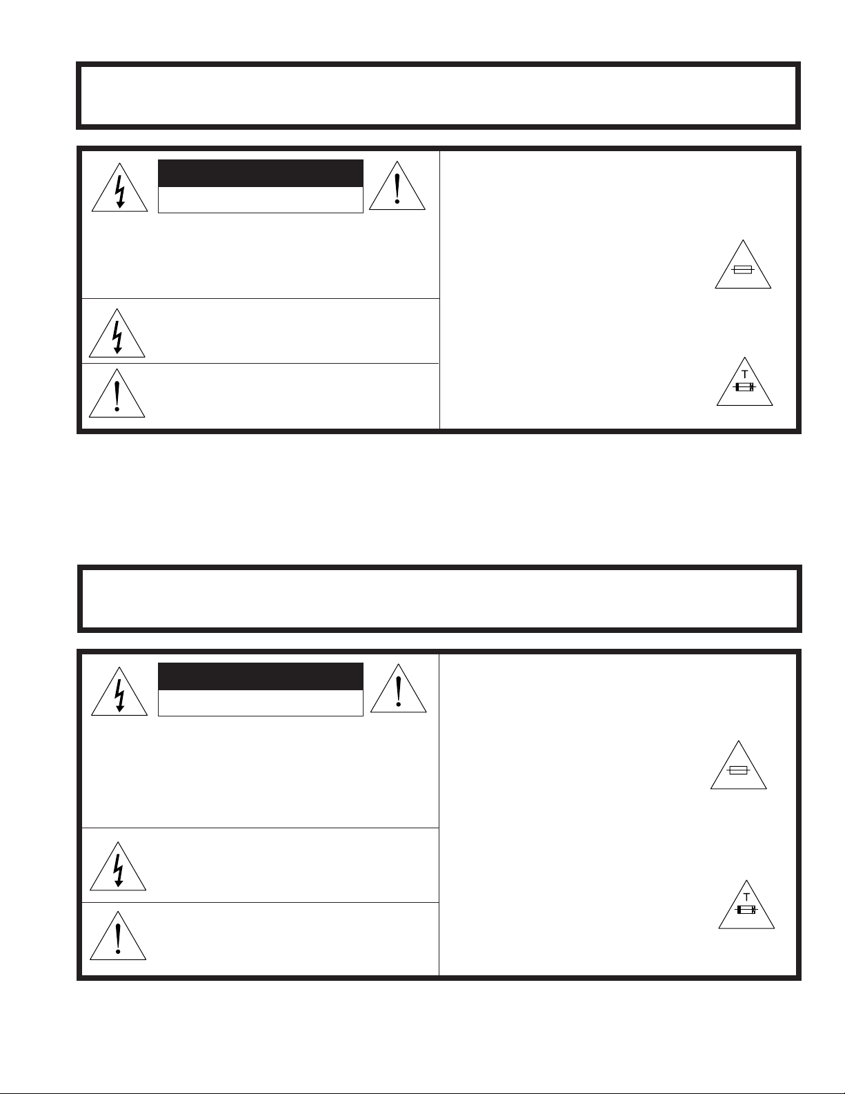
WARNING :TO REDUCE THE RISK OF FIRE OR ELECTRIC SHOCK, DO NO T EXPOSE
THIS APPLIANCE TO WET LOCATIONS.
CAUTION
RISK OF ELECTRIC SHOCK
DO NOT OPEN
CAUTION: TO REDUCE THE RISK OF ELECTRIC
SHOCK. DO NOT REMOVE COVER. NO
USER·SERVICEABLE PARTS INSIDE.
REFER SERVICING TO QUALIFIED SERVICE
PERSONNEL.
CAUTION
This symbol mark means following.
For continued protection against fire hazard, replace only with same type fuse.
(CP901; 2.5A 64V, CP902; 2.5A 64V,
CP903; 2.5A 64V)
Camcorder
only
This symbol warns the user of uninsulated
voltage within the unit that can cause dangerous electric shocks.
This symbol alerts the user that there are
important operating and maintenance instructions in the literature accompanying this unit.
CAUTION
This symbol mark means following.
"RISK OF FIRE–
REPLACE FUSE AS MARKED."
(F101; 2A 250V)
AC Adapter
only
1.5A 250V
ATTENTION:POUR REDUIRE LES RESQUES D'INCENDIE OU DE CHOC ELECTRIQUE,
NE PAS EXPOSER CET APPAREIL A LA PLUIE OU A L'HUMIDITE.
ATTENTION
RISQUE DE CHOC ELECTRIQUE
NE PAS OUVRIR
ATTENTION: AFIN DE REDUIRE LES RISQUES DE
CHOC ELECTRIQUE, NE PAS RETIRER LE
COUVERCLE, AUCUN ORGANE INTERNE
NE PEUT ETRE REPARE PAR
L'UTIUSATEUR, CONFIER L'APPAREIL A
UN DEPANNEUR QUALIFIE.
ATTENTION
Ce symbole signifie que l'on devra utiliser un fusible de même type (CP901;
2,5A 64V, CP902; 2,5A 64V, CP903;
2,5A 64V) pour assurer la sécurité.
Camcorder
seulement
Ce symbole signale à l'utilisateur la présence
d'une tension non isolée à l'intérieur de l'appareil
qui peut être la cause de secousses électriques
dangereuses.
Ce symbole avertit l'utilisateur que des instructions importantes relatives à l'utilisation
et àl'entretien se trouvent dans le manuel
accompagnant l'appareil.
ATTENTION
La signification de ce symbole est la
suivante.
"RISQUE D' INCENDIE – REMPLACEZ
LE FUSIBLE SELON L' INDICATION."
(F101; 2A 250V)
3
Adaptateur CA
seulement
1,5A 250V

VL-AD260U
The following program is available in the United States. Please consult local environmental
authorities concerning the availability of this or other programs in your area.
CAUTION
BEFORE BATTERY DESTROY
NICKEL-CADMIUM BATTERY
The RBRCTM Seal
SHARP participates in the RBRCTM* Nickel-Cadmium Battery Recycling Program in the United
States. The RBRCTM Seal on our battery pack contained in our product indicates that SHARP is
voluntarily participating in an industry program to collect and recycle these batteries. The RBRCTM
program provides you with a convenient alternative to placing spent Nickel-Cadmium battery packs into
the trash or municipal waste stream, which is illegal in some areas. At the end of their useful life, the
Nickel-Cadmium battery can be dropped off at the nearest collection center for recycling. For information
on the nearest collection center, call 1-800-8-BATTERY or your local recycling center. If you are located
outside the United States, contact your local authorities for information concerning proper disposal and/
or recycling of this battery. SHARP’s involvement in this program is part of our commitment to protecting
our environment and conserving natural resources.
[Footnote] *RBRCTM is trademark of the Rechargeable Battery Recycling Corporation.
NICKEL-METAL HYDRIDE BATTERY
LITHIUM or LITHIUM-ION BATTERY
SEALED LEAD BATTERY
Battery disposal
Contains the above (Rechargeable) Battery. must be recycled or disposed of properly.
Remove the Battery from the products and contact Federal or State Environmental Agencies for
information on recycling and disposal options.
4

2. SPECIFICATIONS
Signal System: NTSC standard
Recording System: 2 rotary heads, helical scanning system
Cassette: 8 mm video tape, MP type or Hi8 MP, ME type
Recording/Playback Time: 120 minutes (P6-120)
Tape Speed: 14.345 mm/second
Pickup Device: 1/4" (6.4 mm, effective size: 4.5 mm) CCD image sensor (with approx.
270,000 pixels including optical black)
Lens: 16 × power zoom lens (F1.4, f=4.0-64.0 mm), and full-range auto focus
Lens Filter Diameter: 46 mm
Monitor: 3.5" (8.8 cm) full-color LCD screen (TFT active matrix)
Microphone: Electret monaural microphone
Color Temperature Compensation: Auto white balance with white balance lock
Minimum Illumination: 0.8 lux (5 lux measured by EIA standard) (with gain-up, F1.4)
Still Image Compression System: JPEG base line conformance
Still Image Recording Format: JPEG (Exif2.1)
Still Image Recording Medium: 3.3 V type SmartMedia
Video Output Level: 1.0 Vp-p 75-ohm unbalanced
Audio Output Level: –8 dBs, impedance less than 2.2 kohms
Speaker Output: 200 mW
Power Requirement: DC 3.6 V (with battery pack)
DC 7.0 V (with AC adapter)
Power Consumption:
5.4 W (during camera recording in full auto mode with zoom motor off,
backlight in normal mode and DIS function off)
Operating Temperature: 32°F to 104°F (0°C to + 40°C)
Operating Humidity: 30% to 80%
Storage Temperature: –4°F to 140°F (–20°C to +60°C)
Dimensions (approx.): 7
7
/32" (W) × 4 9/32" (H) × 3 7/8" (D)
[183 mm (W) × 109 mm (H) × 99 mm (D)]
Weight (approx.): 1.62 lbs (735 g) (without battery pack, lithium battery, SmartMedia
card, video cassette, and lens cap)
TM
card (SSFDC)
VL-AD260U
TM
AC Adapter
UADP-0312TAZZ
Power Requirement: AC 110-240 V, 50/60 Hz
DC Output: 7.0 V
Power Consumption: 15 W
Dimensions (approx.): 2
Weight (approx.): 0.68 lbs (308 g)
11
/16"(W) × 115/32"(H) × 513/32"(D)
[68 mm (W) × 37 mm (H) ×
137 mm (D)]
Memory Capacity: 8 MB
Power Requirement: 3.3 V
Operating Temperature
Storage Temperature
SmartMediaTM Card
(Supplied Accessory)
Memory Type: NAND flash EEP-ROM
:32°F to 104°F
(0°C to + 40°C)
:–4°F to 149°F
(–20°C to +65°C)
Specifications are subject to change without notice.
SERVICE INFORMATION (For the U.S.)
For the location of the nearest Sharp Authorized Service, or to obtain product literature, accessories,
supplies or customer assistance, please call 1-800-BE SHARP (1-800-237-4277) or visit SHARP's
website (http://www.sharp-usa.com)
5
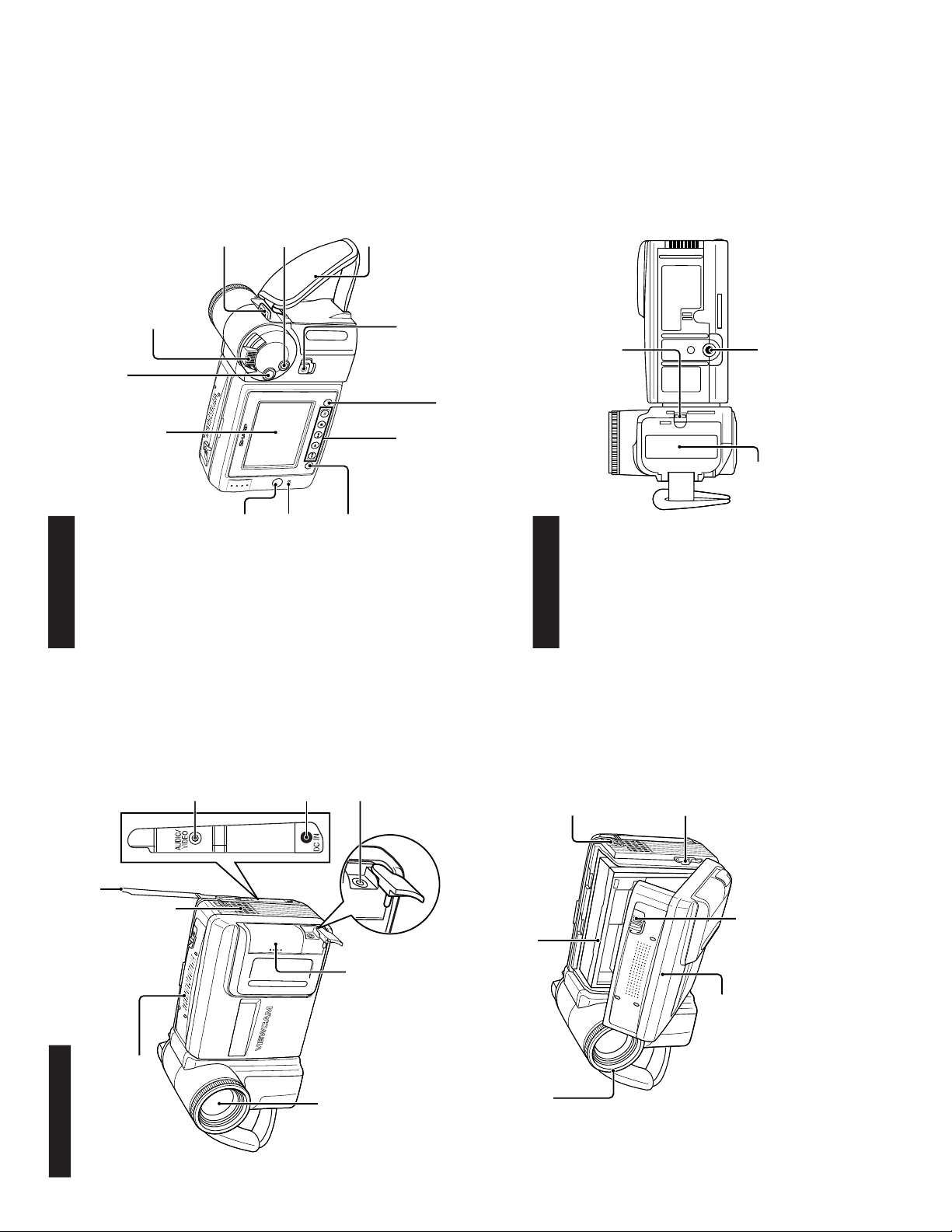
VL-AD260U
Front view
When the cassette compartment door is open
Zoom lens
Microphone
Terminal cover
AUDIO/VIDEO
jack
DC IN jack
Speaker
PC connection jack
Card slot door
Lens hood
Cassette holder
Shoulder strap loop
Lithium battery holder
Cassette compartment door release
Cassette compartment
door
Rear view
Bottom view
Remote sensor
CHARGE indicator
MENU button
Operation buttons
DISPLAY button
LCD monitor screen
RECord START/STOP button
Power Zoom Wide angle/
Telephoto control
VOLume control
Shoulder strap loop
TAPE/CARD button
Hand strap
Power switch (CAMERA/VCR
select switch)
Battery compartment door release
Tripod socket
Battery compartment
door
3. PART NAMES AND FUNCTION
For details on the use of each control.
6
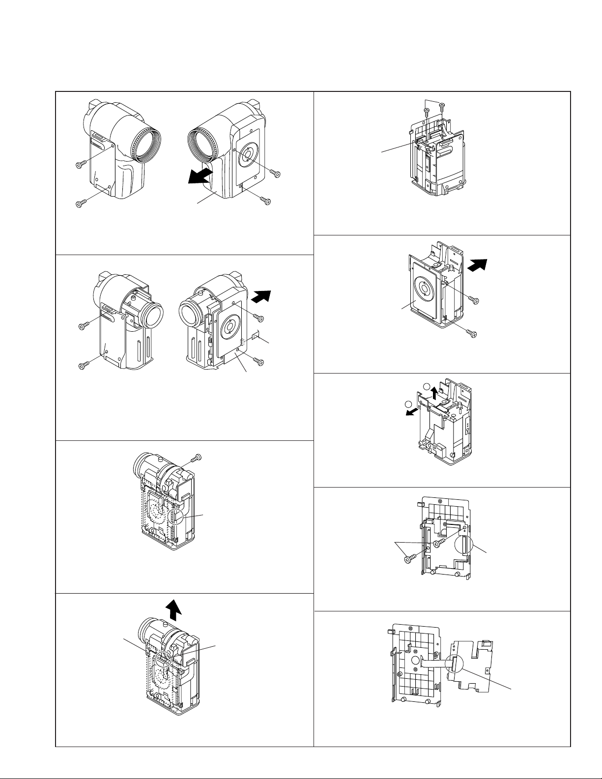
4. DISASSEMBLY OF THE SET
4-1. REMOVAL OF THE CAMERA SECTION
Note:
Before removing the cabinet, turn off the power supply, and ascertain that the battery has been removed.
(b)
VL-AD260U
(b)
(d)
Pull out
(1)
Camera front cabinet
(a)
(a)
1. Remove one screw ((d)XiPSF20P04000), one screw ((b)LXHZ0018TAFF), two screws ((a)LX-HZ0018TAFN), and pull
out the camera front cabinet (1).
Pull out
(a)
(b)
Connector
(d)
(2)
Camera rear cabinet
(a)
2. Remove one screw ((b)LX-HZ0018TAFF), one screw
((d)XiPSF20P04000) and two screws ((a)LX-HZ0018TAFN)
and pull out the camera rear cabinet (2) backwards.
Remove the FPC in the camera rear cabinet.
Connector
5. Remove the connector of the 6-cell detection switch, and
remove two screws ((b)LX-HZ0018TAFF) fixing the battery
catcher.
Pull out
(b)
Tilt frame C
(b)
6. Remove two screws ((b)LX-HZ0018TAFF) and pull out the
camera side cover from the tilt frame C.
1
2
(c)
CCD
connector
3. Firstly, remove the CCD connector from the Camera PWB, then
remove one screw ((c)LX-HZ0045TAFN), the reverse side in this
figure (Not remove the lens holder in this section).
Pull out
Lens holder
Lens connector
4. Pulling the lens holder, and pull out the lens upwards. Then,
remove the lens connector.
7. Remove the battery catcher from the camera side cover.
(c)
Connector
8. Remove one connector of the camera PWB, and remove two
screws ((c)LX-HZ0045TAFN) fixing the PWB.
Connector
9. After removing the camera PWB from the tilt frame, remove
the connector on the rear of the PWB.
7
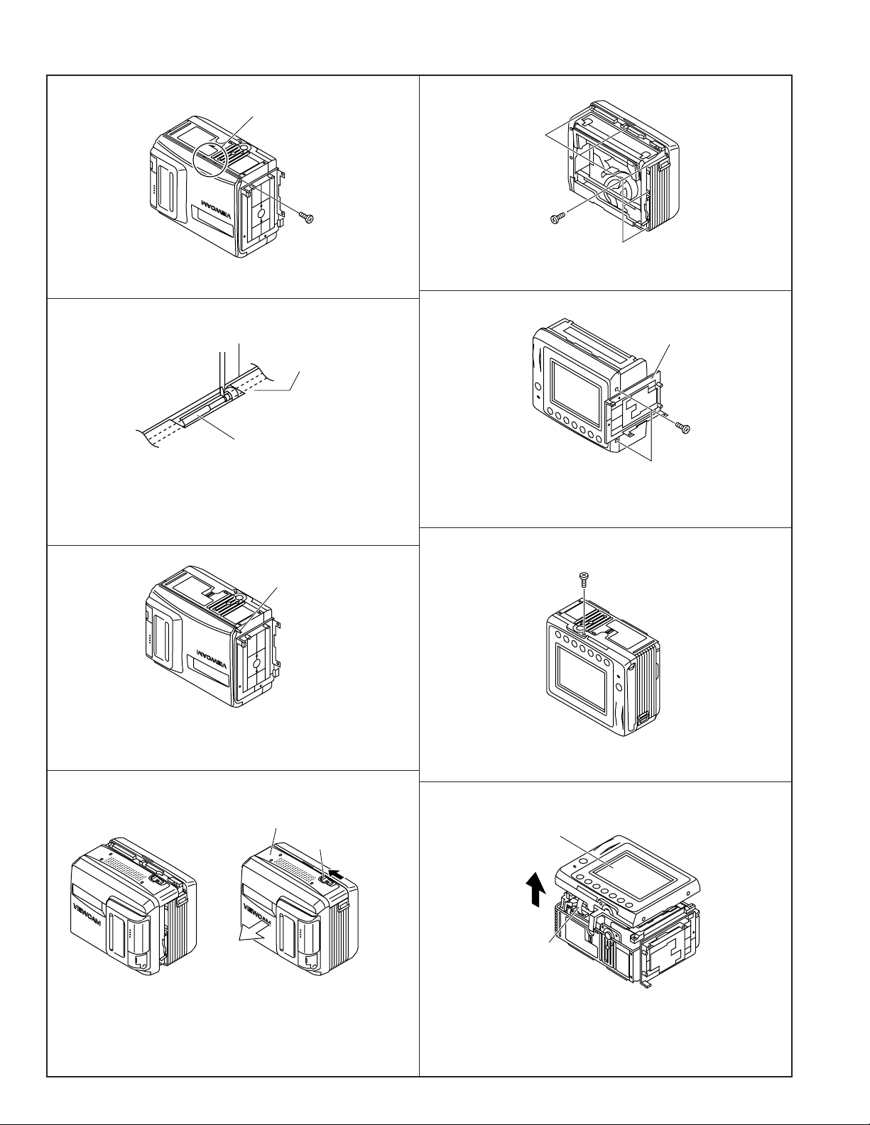
VL-AD260U
4-2. DISASSEMBLY OF THE VCR MAIN BODY
<1. Removal of the VCR lid shaft>
Area A
(k)
(1) Remove one screw ((k)LX-HZ0063TAFC).
<Detail of area A>
VCR lid
Frame V
VCR lid shaft
(2) Bring the jig (example: slotted precision screwdriver) into
contact with the removal groove of the VCR lid shaft, and
slide the screwdriver with care to prevent injuring the VCR lid
and frame V.
VCR lid shaft
(b)
(2) Remove five screws ((b)LX-HZ0018TAFF).
Tilt frame C
(i)
(3) Turn the tilt frame C so that the screwdriver can be easily
inserted, and remove two screws ((i)XiPSN20P04000).
(i)
(3) Pull out the VCR lid shaft head which projects beyond the
surface of the VCR lid.
<2. Disassembly of the cabinet L>
VCR lid
VCR lid knob
(1) Slide the “VCR lid knob” in the arrow direction, and slide the
VCR lid in the arrow direction as far as the cabinet L fastening
screw is visible. (Left figure) Since the connector of the
microphone is still connected, take care to prevent excessively sliding the VCR lid.
(4) Remove one screw ((i)XiPSN20P04000).
Cabinet L
FPC connector
(5) Remove the cabinet L to the midway, and disconnect the FPC
connector.
8
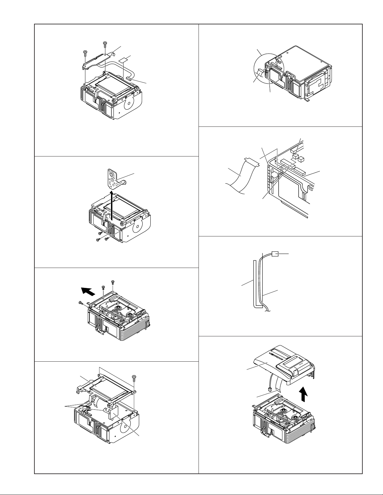
VL-AD260U
<3. Removal of the AV unit and AV unit cover>
(b)
(b)
AV unit FPC
Wire fixing tape
AV unit wire
(1) Peel the wire fixing tape.
(2) Remove the AV unit wire.
(3) Remove the AV unit FPC.
(4) Remove two screws ((b)LX-HZ0018TAFF) fixing the AV unit
and LCD holder.
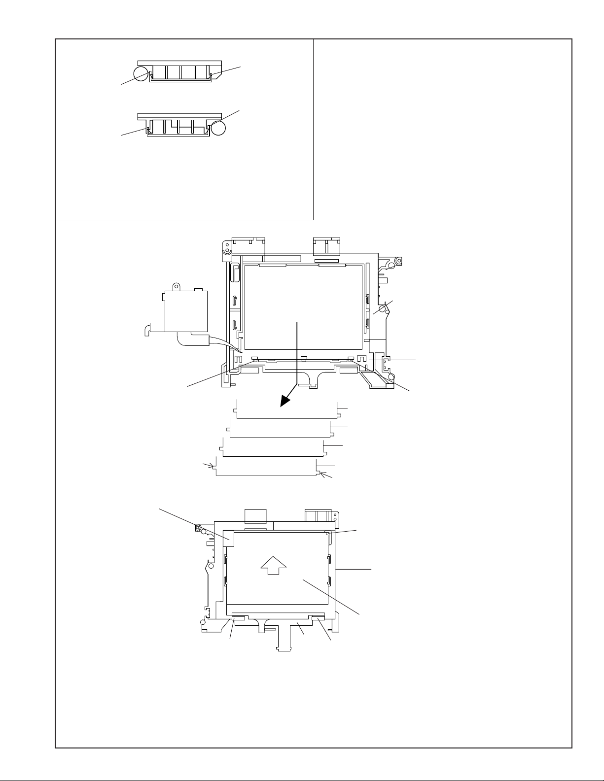
<4. Disassembly of the LCD holder>
Tripod angle
<5. Removal of the VCR lid>
Area B
Card FPC
Microphone connector
(1) Disconnect the microphone connector.
<Detail of area B>
Microphone connector
Card FPC
Card FPC connector
Microphone connector
Microphone wire
spacer
(d)
(d)
(d)
(1) Remove three screws ((d)XiPSF20P04000) pull out the
tripod angle.
Pull out
(b)
(b)
(b)
(2) Remove three screws ((b)LX-HZ0018TAFF) on the tilt frame V.
Move the tilt frame V by a looseness of the tilt FPC.
LCD unit
Connector
(b)
(2) Remove the connector cable from the hole of the microphone
wire spacer.
<Detail of area B>
Microphone connector
Frame V
Microphone wire spacer
(3) Remove the microphone wire spacer from the frame V.
VCR lid
Card FPC
Inverter transformer
(3) Remove two screws ((b)LX-HZ0018TAFF) and two connec-
tors, and remove the LCD unit (with inverter) from the main
body.
(4) Pull out the microphone wire cable with care to prevent it from
interfering with the mechanical parts, and remove the VCR
lid.
9
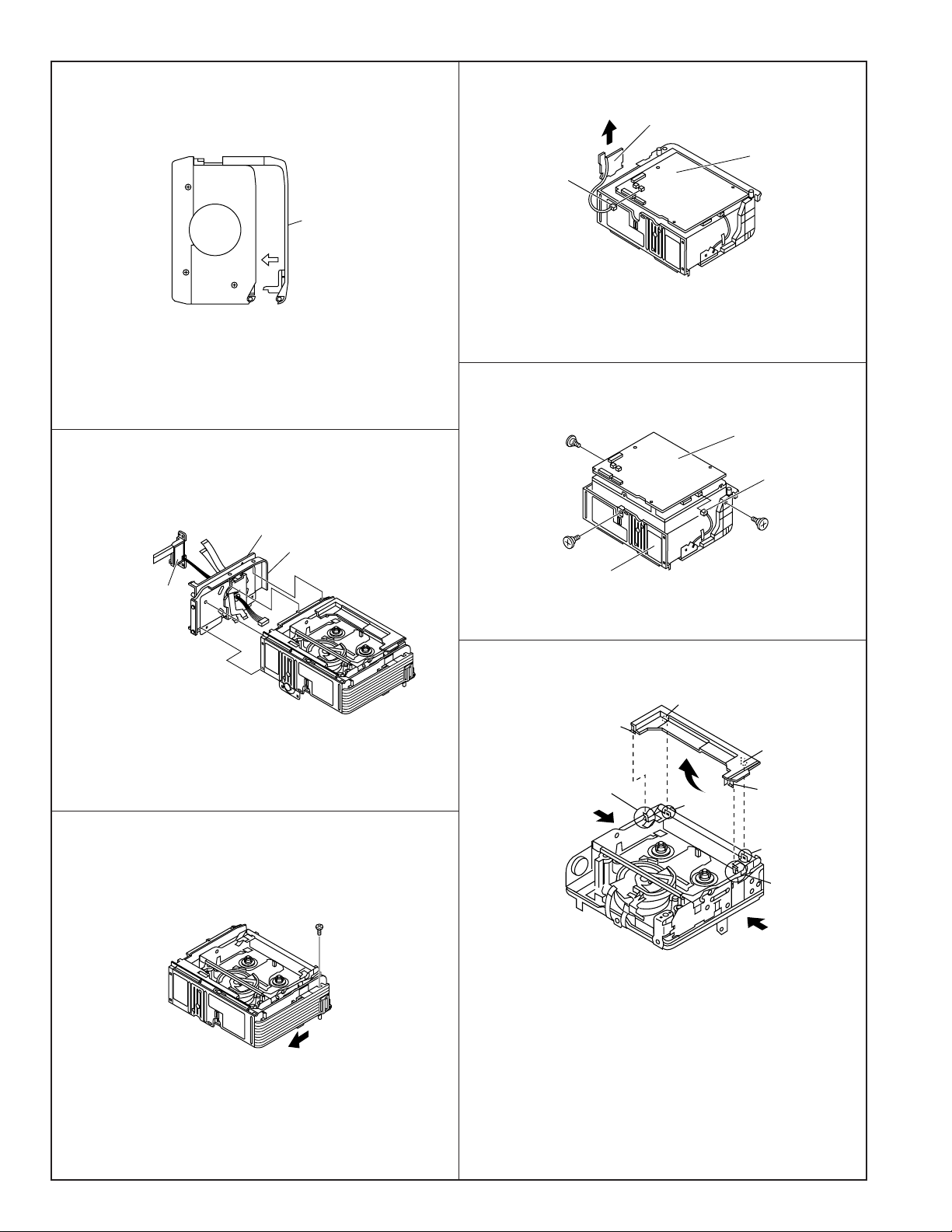
VL-AD260U
Caution for installation of the VCR lid
VCR lid
When installing the VCR lid, move the VCR lid in the arrow
direction, keeping the VCR lid parallel to the main body as
shown above.
<6. Removal of the tilt unit>
<8. Removal of the Lithium PWB>
Lithium PWB
Main PWB
Connector
(1) Remove the connector of the Lithium PWB from the Main
PWB.
(2) Move the lithium unit in the direction of the arrow.
<9. Disassembly of the frame V>
(e)
Mechanism unit
Connector
Tilt frame C
Tilt frame V
Battery terminal
unit
(1) Disconnect three connectors.
Remove the tilt unit from the cabinet of the main body.
<7. Removal of the speaker cover>
(b)
(e)
Frame V
(e)
(1) Remove three screws ((e)LX-BZ0191TAFD) and one con-
nector, and remove the frame V from the main body.
<10. Removal of the cassette compartment lid>
B
C
A
C
E
B
D
A
D
F
(1) Remove the screw ((b)LX-HZ0018TAFF) fixing the speaker
cover.
(2) Move the speaker holder in the direction of the arrow to
remove it.
(1) Using the slotted precision screwdriver, push and turn the
two claws (C and D) which fasten the cassette compartment
lid, and the cassette compartment lid will be removed from
the hook area of the cassette component.
(2) Turning the cassette compartment lid in the arrow direction,
lift it, and the claws A and B will be disengaged to remove the
cassette compartment lid.
Note:
Take care to prevent breaking the claws of the cassette compartment lid.
10
Claw C
VL-AD260U
Claw B
Claw D
View E
Claw A
View F
Note:
When fixing the cassette compartment lid, first engage the claws
A and B, and then engage the claws C and D, verify that the four
claws (A, B, C and D) of the cassette compartment lid are
securely engaged as shown in the view above.
<11. Disassembly of the LCD panel>
(2)
(1)
Claw (A)
Disengage the claw, and remove the
LCD panel.
(3)
Claw (A)
Lugs
Arm(E)
(C)
FPC
Reflection sheet
Light guide plate
Diffusion sheet
Prism sheet
Lugs
Claw (B)
(2)
(4)
Arm(D)
1. Disengage two claws (A), and remove the lamp inverter unit (1) from the LCD holder (2).
2. Remove the sheets from the LCD holder (2).
3. Pull the LCD glass retaining (3).
4. Remove the FPC from Arm(D) and (E).
5. Disengage the claw (B), and slide the LCD panel (4) in the (C) direction to remove the LCD holder (2).
Note:
When handling the prism sheet, diffusion sheet, light guide plate and, reflection sheet do not touch any parts other than lugs and sides.
Put the light guide plate and reflection sheet between reflectors of lamp. Therefore, install them together with the lamp ass'y.
11
VL-AD260U
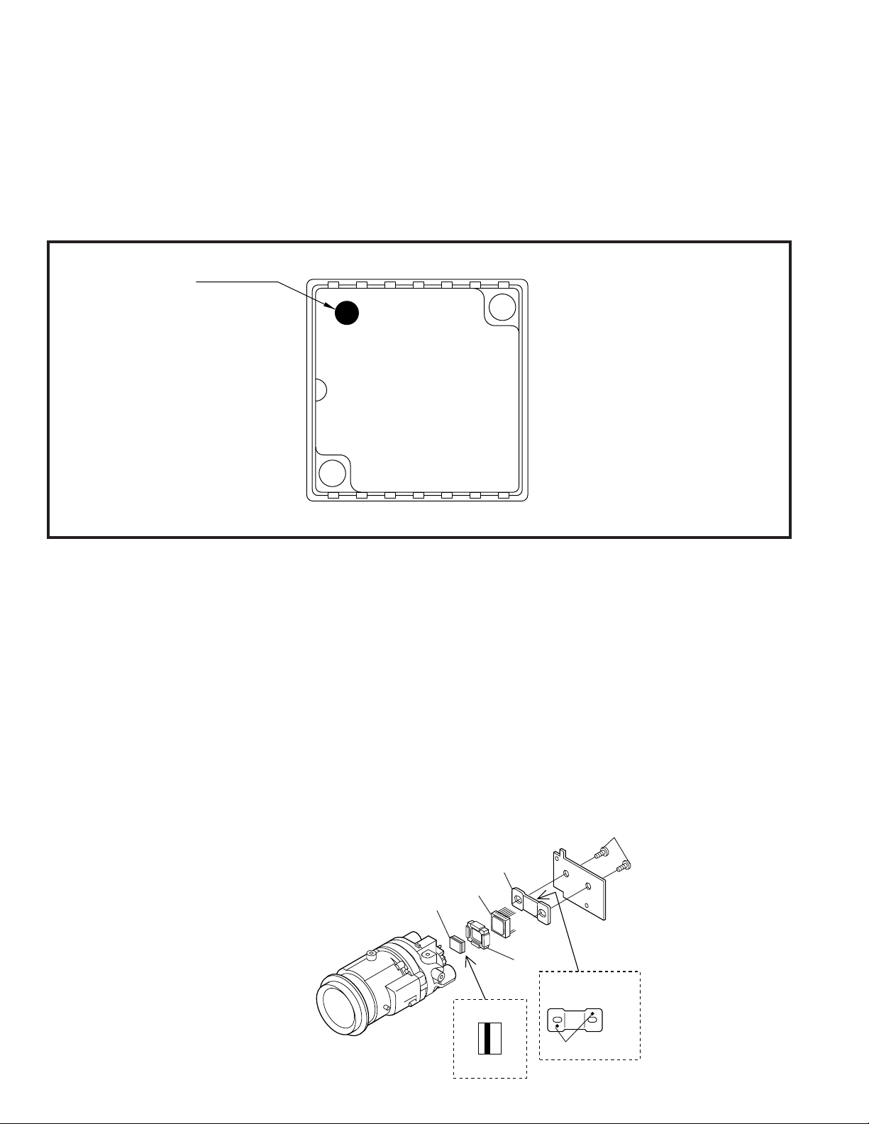
4-3. REPLACEMENT OF CCD SENSOR
4-3-1. BEFORE REPLACEMENT
1) The CCD image sensor is more sensitive to electrostatic breakage than C-MOS LSI. Therefore sufficient means to prevent
electrostatic damage must be taken when it is replaced.
• Ground the soldering iron.
• Ground also the human body, using the wrist strap(through an 1 M ohm resistor).
• Until the CCD sensor is mounted on the PWB, fit it to the conductive sponge, and short-circuit the foot lead.
2) Take utmost care so that the surface glass of CCD sensor and optical filter are not contaminated and damaged. If any contamination
is found, for example fingerprint, wipe it off with silicon paper or clean chamois skin.
3) When replacing the CCD sensor, use the static electricity prevention grounded soldering-iron, and perform quickly soldering.
Index Mark
17
JAPAN
SHARP
LZ2413H5
YYWWXXX
14 8
4-3-2. REMOVAL OF CCD
1) Unsolder the CCD sensor leads from the sensor PWB.
2) Take out the sensor PWB.
3) Remove the two screws (6), and remove the sensor holder and CCD sensor.
4-3-3. MOUNTING OF CCD
1) Place the lens unit upright (since the CCD sensor mount ID faces upward, care must be taken so as not to damage the front lens of
unit), put the crystal filter first and then the dust protection rubber into the CCD holder of lens unit. Set the crystal unit with its thin side
toward the lens unit.
2) Place the CCD sensor so that the its No. 1 pin is at the right lower (Positioning hole to be at right), and put the CCD sensor into the
CCD holder. For smooth and tight fitting, press the right lower part of back of CCD sensor, and then press the left upper part.
Note: Pay attention to the direction of CCD sensor.
3) Place the sensor holder so that its two round markings be visible, and fix the sensor holder with the two screws ((6)LX-HZ0013TAFF).
4) Mount the sensor PWB so that the CCD sensor leads go thorough the PWB holes.
5) Solder the CCD sensor lead to the sensor PWB.
Note: Take care not to apply excessive heat.
CCD Sensor
Crystal
Sensor Holder
Lens
Side
The THIN SIDE
faces the lens
CCD
Side
Rubber
The mark must be on
this face.
Mark
(6)
12

5. MECHANISM ADJUSTMENT
5-1. MECHANISM CHECKING/ADJUSTING JIGS, TOOLS AND PARTS
5-1-1. Mechanism checking/adjusting jigs and tools
<Note: The entries of list>
VL-AD260U
Configuration
1. Name
2. Part No.
3. Code
* Model, Uses Remarks
1. Cassette torquemeter
for PB
2. JiG8T-012
3. CV
* (10 g·cm/25 g·cm)
1. Master plane
2. JiGMP-MX7U
3. CG
* For adjustment of Tu guide
height, Si roller height and
checking of reel disk height
1. Hex wrench
3. —
*
For loosening or tight-
ening of Motor stator
(1.3 mm)
1. Cassette torquemeter
for VS-REW
2. JiG8T-032
3. CV
* (50 g·cm/25 g·cm)
1. Height adjusting jig
2. 9DAGH-E31S
3. BM
* For adjustment of Tu
guide height and Si
roller height
1. Tension Band and Plate
Adjusting Jig
2. JiGDRiVERMX7U2
3. BN
1. Torque gauge
2. JiGTG0045
3. CN
* For measurement of
loading brake torque
1. Tu guide height
adjusting driver
2. 9EQDRiVER-V712
3. BL
1. Torque gauge head
2. JiGTH-MX7U
3. BS
* For torque gauge listed
left
1. Guide roller height adjusting driver
2. JiGDRiVERHMX7U
3. BU
* Bit shape (See the figure above.)
1. Alignment tape
2. VR2ABOPS
3. BT
TAPE CONTENTS
VIDEO IMAGE AUDIO TIME
MONOSCOPE L-CH 400Hz 30MIN
R-CH 1,000Hz
1. Torque driver
(1.5 kg·cm)
2. JiGTD1500RT0H
3. CB
Tolerance±0.1
2
1.8
Edge
4
thickness 0.5
<Others>
(1) Slide calipers
(2) High-precision screw-
drivers (Phillips head,
slotted head)
(3) Radio pliers (with thin
jaws)
(4) A pair of tweezers
5-1-2. Parts for periodic inspection and maintenance.
1. Oil
COSMOHYDRO HV100
* Cosmo Oil Co., Ltd.
1. Greases
Morycoat YM-103/X5-6020
* Dow Corning
1. Screw locking agent
(1401B)
* Three Bond
1. Cleaning liquid
(Industrial-use ethyl alcohol)
1. Cleaning paper
2. JiGDUSPER
3. AP
* Dusper ∑ (Sigma) (Ozu Co., Ltd.)
13
<Note: The entries of list>
1. Superfine swab
* Commercially available
item
Configuration
1. Name
2. Part No.
3. Code
* Model, Uses Remarks
VL-AD260U
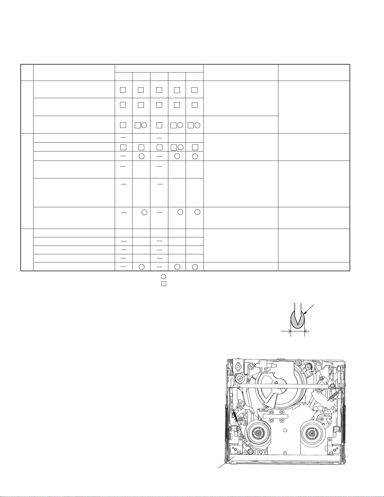
5-2. ITEMS AND TIMINGS OF INSPECTION AND MAINTENANCE
The mechanism of VCR needs the following periodic inspection and maintenance in order that it maintains its high quality. Also,
after the machine is repaired, execute the following maintenance and checks regardless of how long it has been used.
5-2-1. Inspection and maintenance list
Checking/Maintenance point
Tape travel system
Tape travelling route
(Refer to Section)
Drum (Refer to Section)
Video head
Timing belt
Pinch roller
Capstan D.D. motor
Driving system
Relay Pulle shaft
Pulle gear shaft
Drive gear shaft
Loading motor • Replace if failure (abnor-
Performance check
Abnormal sound
PB/VS-REW take-up torque
PB/VS-REW back tension torque
Tu brake
HC (Head Cleaner)
500 1,000 1,500 2,000 3,000
Oil: COSMOHYDRO HV100
Greases: MORYCOAT YM-103/X5-6020
Screw locking agent: THREE BOND 1401B
Cleaning liquid: Industrial-use ethyl alcohol
Usage time (hrs.)
★★★
∆∆∆
∆∆∆
★★★
★★★★★
★★★
★★★
★★★
: Replace.
: Clean.
∆ : Apply oil.
★ : Check.
5-2-2. Notes and cautions
(1) Any cut washers, once removed for parts replacement or for other
reason, must be replaced with new ones.
(2) The mechanism of this VCR does not involve any volume adjustment.
If the specified range is not satisfied, either cleaning or replacing the
parts is required.
(3) Oils
a) Be sure to use the specified oils (different viscosity may cause
troubles).
b) For the bearings, be sure to use oil that is free form dust and other
foreign substances. (Dust or foreign substance contained in the oil
may cause wear or seizure of the bearings.)
c) A drop of oil represents the amount of oil which is held on the needle
top as shown in the Figure 1.
(4) The circuit repair must be executed without removing the V frame.
(5) For operating the mechanism alone, actuate it with the motor. The
terminal-to-terminal voltage must be DC4V or less.
(6) When installing the cassette control, press the part A shown in Figure
2.
*Do not press other parts.
(7) Take care so that the whole mechanism is not deformed.
Possible symptom
encountered
• Lateral noise
• Unclean head
• Screen shaking
• Improper S/N ratio
• No color appears.
• Tape does not run.
• Tape slackens.
• Screen shakes.
• Abnormal sound • Apply oil.
• Not ejectable
• The specific mode cannot
be set.
Diameter φ1.5 or less
Remarks
Rollers
• If abnormal rotation or deflection (significant) is
found, replace the roller.
Other than rollers
• Clean the tape contacting
areas. Be sure to use the
specified cleaning agent.
• Replace if failure is found.
(Oil : COSMOHYDRO
HV100)
Note:
After oil is applied to the
drive gear shaft, slightly
wipe it off with swab.
mal sound) is detected.
• If conformance to the
standard is not ensured,
replace part.
Figure 1
Oil
14
A
Figure 2
VL-AD260U
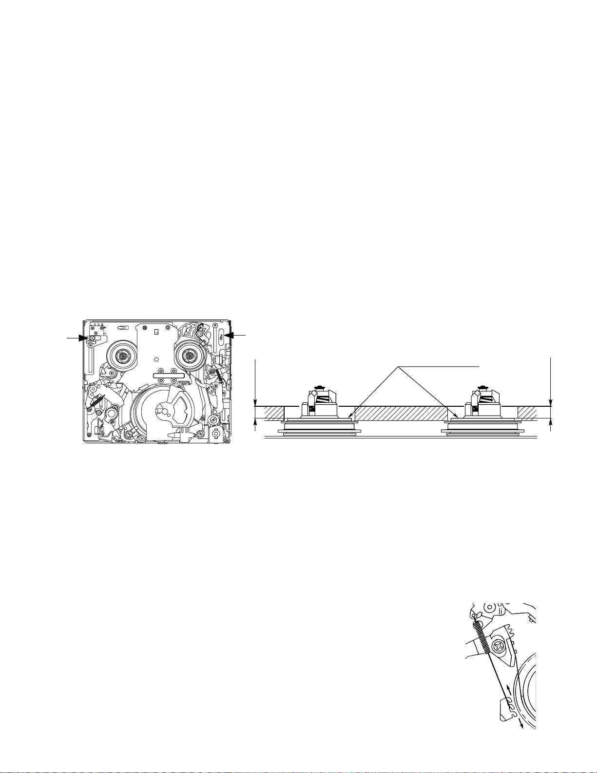
4.4 ± 0.15
Reel support surface
4.4 ± 0.15
5-3. MECHANISM CHECKS AND ADJUSTMENTS
The description given below relates to the general field services, but does not relate to the adjustment and replacement that require
high level equipments, jigs, and technical skills.
In order to maintain the initial characteristics of the machine, it is necessary to execute the maintenance and check and to prevent
damage to tapes and other parts. For adjustments which need jigs, be sure to use the jigs.
Notes and cautions
(1) For mechanism checks and adjustments, be sure to use the AC adapter as the power supply.
(2) For running the tape, be sure to install the cassette control ass’y in advance. (If the cassette control ass’y is to be removed
subsequently after its installation.)
5-3-1. Checking the reel disk height
(1) Remove the cassette control ass’y.
(2) Taking due care not to let the master plane touch the tape running areas such as the drum and the guide rollers, position the
master plane so that the two guides (A and B in the Figure 1) are set in the holes of master plane, then properly set it in the
mechanism.
(3) Using the slide callipers or the like, check that the distance from the upper surface of master plane to the reel support surface
of the S/Tu reel disk is within the specified range. (Figure 2)
Note:
When measuring, do not apply excessive force to the reel support surface of reel disk.
(4) If the measurement is not within the specified range, replace the reel disk ass’y.
(5) Check the items (2) to (4) above in the following two modes.
a) Standby mode
b) Playback (recording) mode
B
A
Figure 2Figure 1
5-3-2. Checking the take-up torque for playback (recording)
(1) Set the torque cassette (JiG8T-012) in position, and check in the SP-mode recording mode (tape recorded in SP mode) that
the torque at the tape taking-up side is within the standard range.
Standard of take-up torque for SP-mode recording (playback)
9 ± 3 g·cm with ripples less than 4 g·cm
(If the torque ripples appear, read the center value of torque between the ripples.)
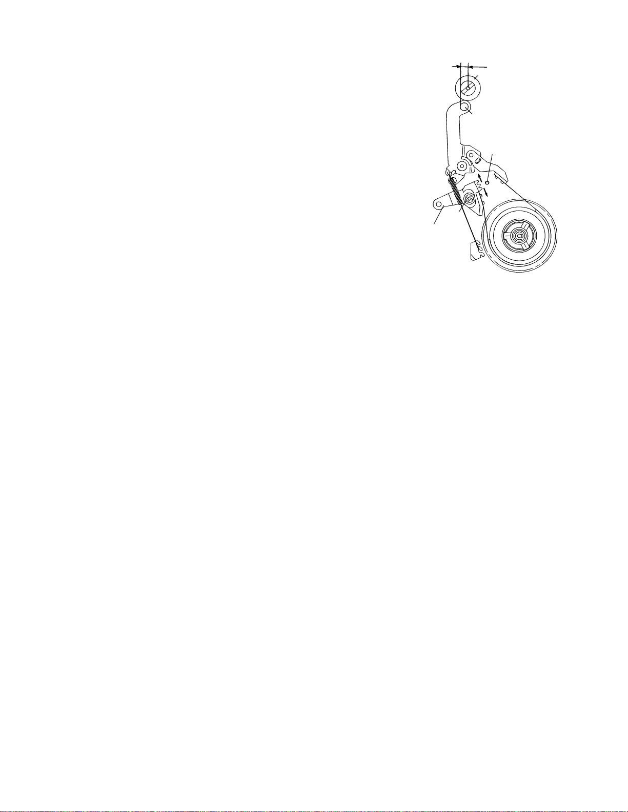
5-3-3. Checking and adjusting the back tension torque for playback (recording)
(1) Checking
1) Set the torque cassette (JiG8T-012) in position, and check in the SP-mode recording mode
(tape recorded in SP mode) that the torque at the tape supply side is within the standard
range.
Standard of back tension torque for SP-mode recording (playback):
8 ± 2 g·cm with ripples of less than 2 g·cm
(Torque ripple must be within 8 ± 2 g·cm)
(2) Adjustment
1) If the back tension torque is not within the standard range, adjust the tension spring hooking
position. If the back tension is too high, hook the spring in the direction A. If the back tension
is too low, hook the spring in the direction B.
Note:
1. After back tension torque adjustment be sure to check the tension pole position.
A
B
15
VL-AD260U
5-3-4. Checking and adjusting the tension pole position
(1) Check
When winding of P6-120 tape is started, check whether the tension pole is in the
specified position against Si roller as shown or not.
If it is not in the specified position, remove the cassette and adjust the position
in the following procedure.
(2) Adjustment
1. Don’t set up any tape, and select the PB mode. (Refer to Item 5-5-1-(4).)
2. Slightly loosen the screw (a) (to such a strength as the T band holder B can
be moved).
3. If the tension pole is in the inner position than specified, dislocate the T band
holder B in the arrow (A) direction and if it is in the outer position, dislocate it
in the arrow (B) position. Then, tighten the screw (a). (For reference, dislocate
it 0.4 to 0.8 mm outer from the position specified above.) For the position
adjustment, it is convenient to use the position adjustment screwdriver
(JiGDRiVERMX7U2). (Set it in the hole (C).)
4. Check the position in the “(1) Check” procedure described above.
5. If it is not in the specified position, repeat the adjusting procedure 1 thru 3.
Note:
• Tightening torque of screw (a) 70 mN·m
• To check the position, be sure to run the tape.
• If the cassette compartment assembly is removed, it makes the work easier. (Refer
to Item 5-5-3.)
T Band
Holder B
Screw
(a)
0
3 – 0.5
Si roller
Tension pole
Hole (C)
(B)
(A)
5-3-5. Checking the take-up torque for rewind playback (VS-REW)
(1) Remove the cassette compartment ass'y and set to the sensor OFF mode.
(2) Set the torque gauge (JiGTG0045) on the S reel disk, and check in the rewind playback (VS-REW) that the torque at the supply
side is within the specified range.
Standard of take-up torque in rewind playback (SP mode)
31 ± 5 g·cm with ripples less than 5 g·cm.
(If the torque ripples appear, read the center value of torque between the ripples.)
5-3-6. Checking the back tension torque for rewind playback (VS-REW)
(1) Set the torque cassette (JiG8T-032) in position, and check in the rewind playback (VS-REW) mode that the torque at the tape
take-up side is within the specified range.
Standard of back tension torque in rewind playback (SP mode):
14 ± 5 g·cm with ripples less than 5 g·cm
(If the torque ripples appear, read the center value of torque between the ripples.)
16
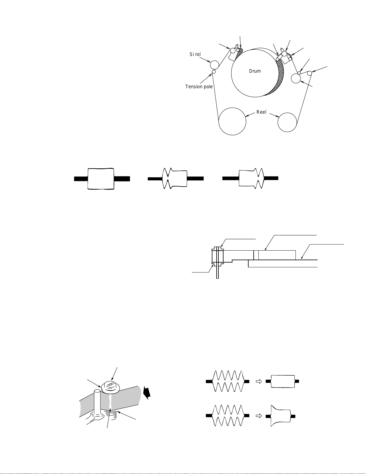
5-4. ADJUSTMENT OF MECHANISM TAPE TRAVEL SYSTEM
Upper flange
Lower
flange
Height adjusting jig
Master plane
(JiGMP-MX7U)
g
Rise waveform
REV OK Playback
REV NG Playback
5-4-1. Preparation for adjustment
(1) Clean the tape running areas (guide poles, rollers, drum,
Capstan shaft, Pinch roller) (Figure 1)
(2) Connect the oscilloscope to the following TPs.
RF output..... TL7410
H-SW-P ....... TL7417
GND............. TL7413
(3) Playback the alignment tape (VR2ABOPS).
(4) Ascertain that each guide is free from remarkable curl.
(5) Ascertain that the RF waveform of inlet and outlet sides is flat
on the oscilloscope (Figure 2, (a)). Unless the waveform is
flat, (Figure 2, (b), (c)), make an adjustment as follows.
Si roller
Tension pole
Sup tilted pole
Sup GR
Tu tilted pole A
Drum
Reel
VL-AD260U
Tu GR
Tu tilted pole B
Capstan shaft
Tu guide
Pinch roller
5-4-2. Adjusting the Sup GR and Tu GR
Tape travel system (Figure 1)
(1) Turn the Sup and Tu guide rollers to get the flat waveform at the inlet and outlet sides.
Inlet side Outlet side
(a) Normal
(b) Inlet side
waveform is disturbed.
(c) Outlet side
waveform is disturbed.
Figure 2
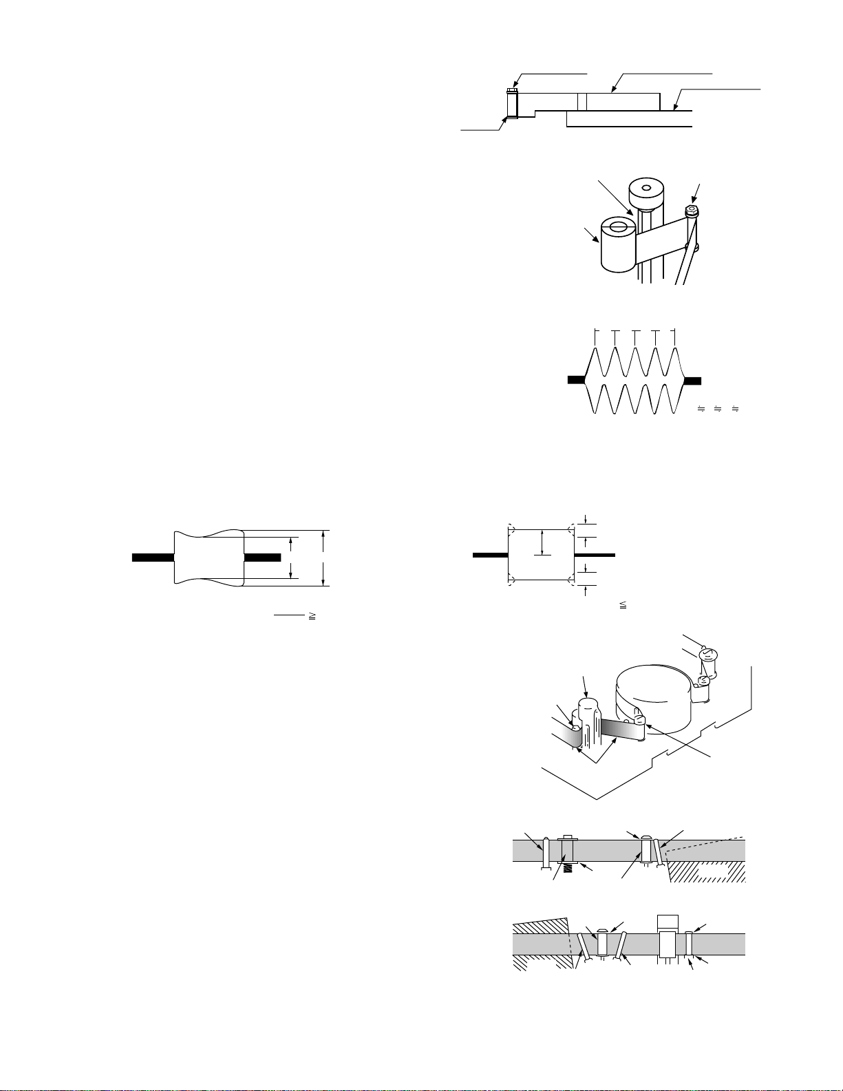
5-4-3. Adjusting the Si roller height
After replacement of Si roller preset and adjust the Si roller
height.
(1) Si roller height presetting
Adjust the height from the upper surface of mechanism
chassis to the upper surface of lower flange with the aid of jig.
Then lower it by 90° (clockwise).
Figure 3
(2) Adjusting the Si roller
1 Playback the tape to set the V/SR mode.
2 Ascertain that the tape is not folded on the lower flange (B) of Si roller. (Figure 4)
If tape folding is found, turn the upper flange (A) of Si roller with the driver (clockwise) to eliminate the folding.
3 Playback the alignment tape (VR2ABOPS).
4 Adjust the Sup GR and Tu GR by the procedure described in section 4-2 above.
5 After V/S F,R perform playback so as to ascertain that the waveform rises horizontally within 2 seconds.
6 Unless the normal waveform is obtained (Figure 5), turn counterclockwise the upper flange (A) of Si roller, and repeat the step
(5) above. Repeat the steps (5) and (6) until the normal waveform is obtained. At this time ascertain that the inlet travel does
not change in the normal playback state. If any change is found, adjust the Sup GR, and redo the step (5).
Si roller
Upper flange (A)
Tape must be free from folden
Figure 4
REV mode
Lower flange (B)
.
Figure 5
17
VL-AD260U
A
C
C
C 1/8A
Capstan shaft
Tu guide
Tape slackness
Tu GR
abcd
a b c d
Upper flange
Lower
flange
Height setting jig
Master plane
(JiGMP-MX7U)
5-4-4. Adjusting the Tu guide
After replacement of Tu guide preset and adjust the height.
(1) Tu guide height presetting
Adjust the height from the upper surface of mechanism chassis to the
upper surface of lower flange with the aid of jig.
(Figure 6)
Figure 6
(2) Adjusting the Tu guide
(Figure 7)
1 Playback the alignment tape (VR2ABOPS).
2 Check that the tape runs at the same height near the capstan shaft in case of
V/S F and V/S R.
3 If the tape running position in case of V/S R is higher than the tape running
position in case of V/S F, turn clockwise the Tu guide nut.
If the tape running position in case of V/S R is lower than the running position
in case of V/S F, turn counterclockwise the Tu guide nut.
5-4-5. Checking the V/S F and R waveforms (Figure 8)
(1) Playback alignment tape (VR2ABOPS), and set the V/S R mode. At this time
ascertain that the waveform crest pitch is kept constant for more than 5 seconds.
(2) Set the V/S F mode. At this time ascertain that the waveform crest pitch is kept
constant for more than 5 seconds.
Unless the constant pitch is obtained, execute the checks of Section 4-2, 3 and
4.
5-4-6. Checking after adjustment
(1) Envelope check
1 Playback the alignment tape (VR2ABOPS).
2 Ascertain that the envelope maximum to minimum ratio is 65% or more. (Figure 9)
3 Ascertain that the waveform does not change remarkably. (Figure 10)
E
MAX
E
MIN
Capstan shaft
Pinch roller
Nut
Figure 7
Figure 8
E
Figure 9
MIN
65 (%)
E
MAX
Figure 10
(2) Rise check
1 Playback the alignment tape (VR2ABOPS).
2 Once eject the cassette, and then load it again.
3 Set the playback mode, and ascertain that the RF waveform rises horizontally
within 2 seconds. At this time ascertain that there is no tape slackness near
the pinch roller.
4 After V/S F, R and FF/REW execute playback, and ascertain that the RF
waveform rises horizontally within 2 seconds. At this time ascertain that there
is no tape slackness near the pinch roller.
Tension pole
(3) Checking the tape travel
1 When the tape is played back, ascertain that tape lift and tape curl of 0.3 mm
Si roller
or more do not occur at the lower flange of Si roller, upper flange of Sup GR,
upper flange of Tu GR, and upper/lower flange of Tu guide.
2 In case of V/S F and R ascertain that no curl is found at each flange.
Drum
Tu tilted pole
5-4-7. Checking and adjusting the playback switching point
Refer to the description of playback switching point adjustment in section of VCR circuit adjustment.
18
Sup GR
Tu GR
Figure 11
Pinch roller
Figure 12
Sup tilted pole
Drum
Tu guide
VL-AD260U
5-5. MECHANISM ASSEMBLING AND PARTS REPLACEMENT
(DISASSEMBLING AND ASSEMBLING)
Below is given an explanation of assembling of mechanism and its parts replacement.
The removal of cabinet and Circuit Board is explained in the relevant service manual.
Notes
1 After removal of cut washers be sure to replace them with new ones.
2 Do not place the mechanism upside down on the table. Otherwise, the mechanism part may be deformed or damaged, resulting
in malfunction.
3 When assembling, take care so that screw, washer or other foreign substance do not enter. Otherwise mechanism malfunction
may occur.
4 Be sure to use the specified cleaning liquid, oil, grease and screw lock as listed below. Otherwise mechanism malfunction may
occur.
Oil: Cosmo Oil Co., Ltd.
COSMOHYDRO HV100
Greases: Dow Corning
MORYCOAT YM-103/X5-6020
Screw lock: THREE BOND
1401B
Cleaning liquid: Industrial-use ethyl alcohol
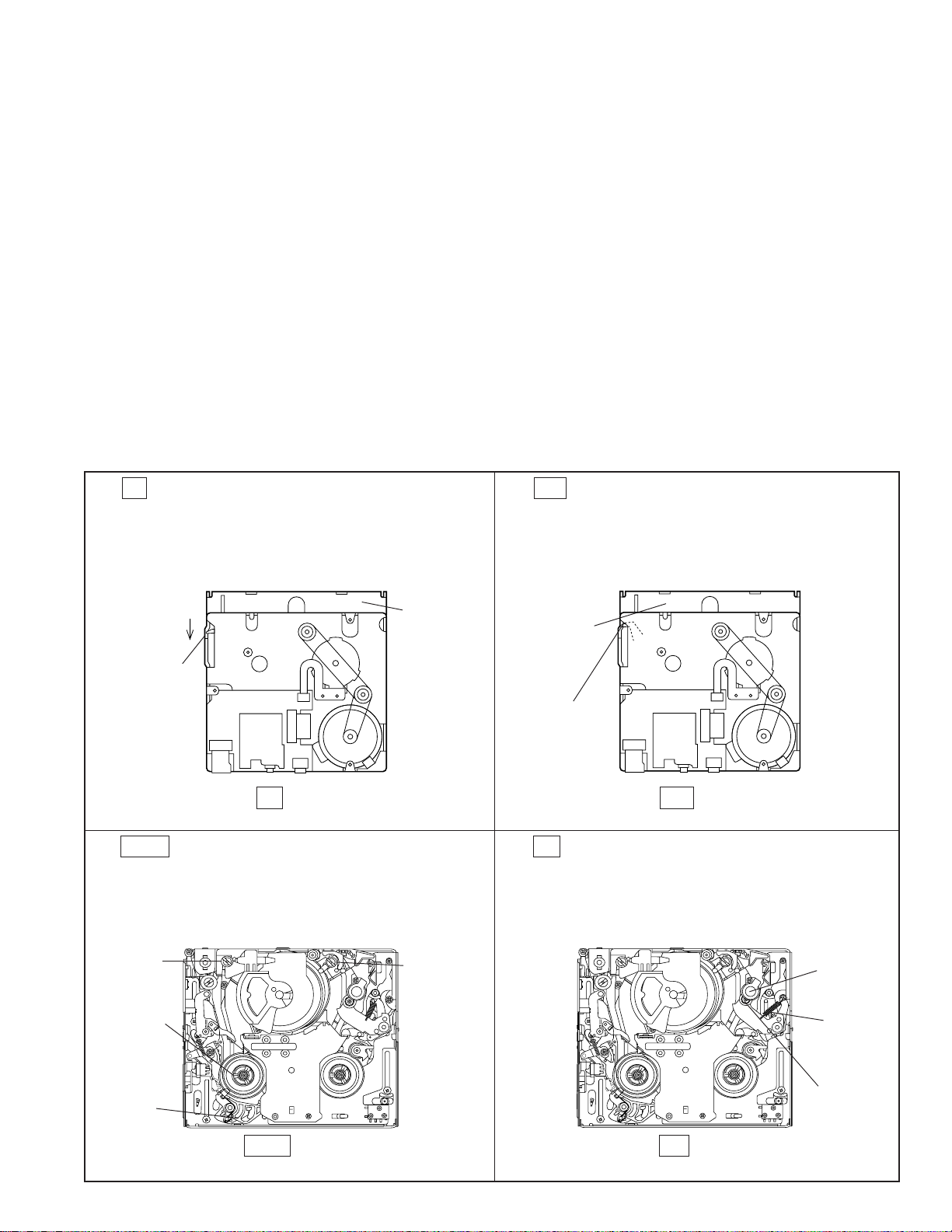
5-5-1. Mechanism modes
To actuate the mechanism, apply DC3 to 4V to the L motor. At this time the L motor connector must have been disconnected in advance.
Below is given an explanation of the mechanism mode necessary for mechanism check, adjustment and replacement.
(1). EJ (Eject) mode (See Figure 1)
In this mode, it is mechanically positioned to eject the
cassette. It is the position where the EJECT lever is moved
the farthest in the direction A in the S/B mode. (In this
mode, the cassette compartment assembly can not be
locked.)
A
A
EJECT
Lever
EJ mode
Figure 1
(3). STOP mode (See Figure 3)
In the STOP mode the S.T pole base is depressed in the
STOP position (or Rec Lock position in CAMERA mode),
and the S brake is in contact with the S reel disk.
Slide
chassis
(2). S/B (Standby) mode (See Figure 2)
When the cassette is loaded, the mechanism is set to the
S/B mode. In this mode the slide chassis is most far from
the drum. In this mode the Eject lever is in position shown
in Figure 2 (in position where the cassette control ass’y
can be locked).
Slide
chassis
EJECT
Lever
S/B mode
Figure 2
(4). PB mode (See Figure 4)
In this mode, it is positioned for the replay, record and so
on. It is the mechanical position where the pinch roller is
pressed against the capstan shaft to make the pinchpressing spring the most longest.
S pole base
S reel disk
S brake
STOP mode
Figure 3
T pole base
Capstan
shaft
Pinch
Spring
Pinch roller
PB mode
Figure 4
19
VL-AD260U
e
c
i
b
j
a
Recognition switch
Cap
Cassette control
down switch
Light guide
Adhesive tape
*
Fixing screw
Drum base Earth spring
Upper/lower drum ass'y
Positioning hole
1
d
f
d
e
e
2
2
2
2
3
i
i
g
f
g
c
c
5-5-2. Cassette control ass’y
<Disassembling>
(1) Set the unit to the EJECT mode, and let the housing stand upright. Or set the
unit to the STANDBY mode, press the lock lever in the arrow direction, and
a
let the housing stand upright. (See Fig. 5: in the direction
pushing in the direction
a
, slightly lift the housing by hand to release the lock
or b) (When
lever.)
(2) Remove the four screws 2 and take out the down guide 3.
c
(3) Slide the two link support shafts
openings
(4) Deflect the roller shafts
g
on the slide chassis. (Be careful not to deform the inner links.)
g
on their respective slide chassis slits (two at
d
a little inward to get them out of the round openings
and the two roller shafts
d
to the round
e
and two at f).
<Reassembling>
(1) Set the unit to the STANDBY mode.
d
(2) Deflect the roller shafts
g
on the slide chassis. (Be careful not to deform the inner links.)
(3) Align the flanges of roller shafts
sliding the flanges, fit the support shafts
a little inward, and fit them into the round openings
d
with the slide chassis slits
c
in the slide chassis slits
f
. While
slide them until they reach the slits.
i
(4) Attach the down guide. (While pressing the guide in the direction
j
the screws until the gap
c
becomes zero.)
between the down guide 3 and the support shafts
Tightening torque: 70±7 mN·m (0.7±0.07 kg·cm)
5-5-3. Actuating the mechanism with the cassette
, tighten
Screw tightening
torque (4 locations)
0.069±0.007 N·m
(0.7±0.07kg·cm)
control ass’y removed
(1) Turn on the power supply with the cabinet and camera unit removed,
referring to the Service Manual (so as to actuate the mechanism).
(2) Put the cap on the light guide.
(3) Press the cassette control down switch through the adhesive tape in
the arrow direction so as to turn it on. At this time take care to avoid
contact with the cassette. Keep the switch pressed (if the switch is
turned off, unloading occurs).
Note: To set the Rec mode, press the pin (marked with the asterisk *)
of recognition switch (this operation is not necessary in other
modes).
, and
Lock Lever
Down Guide
Screw
Figure 5. Lock lever section
Figure 6
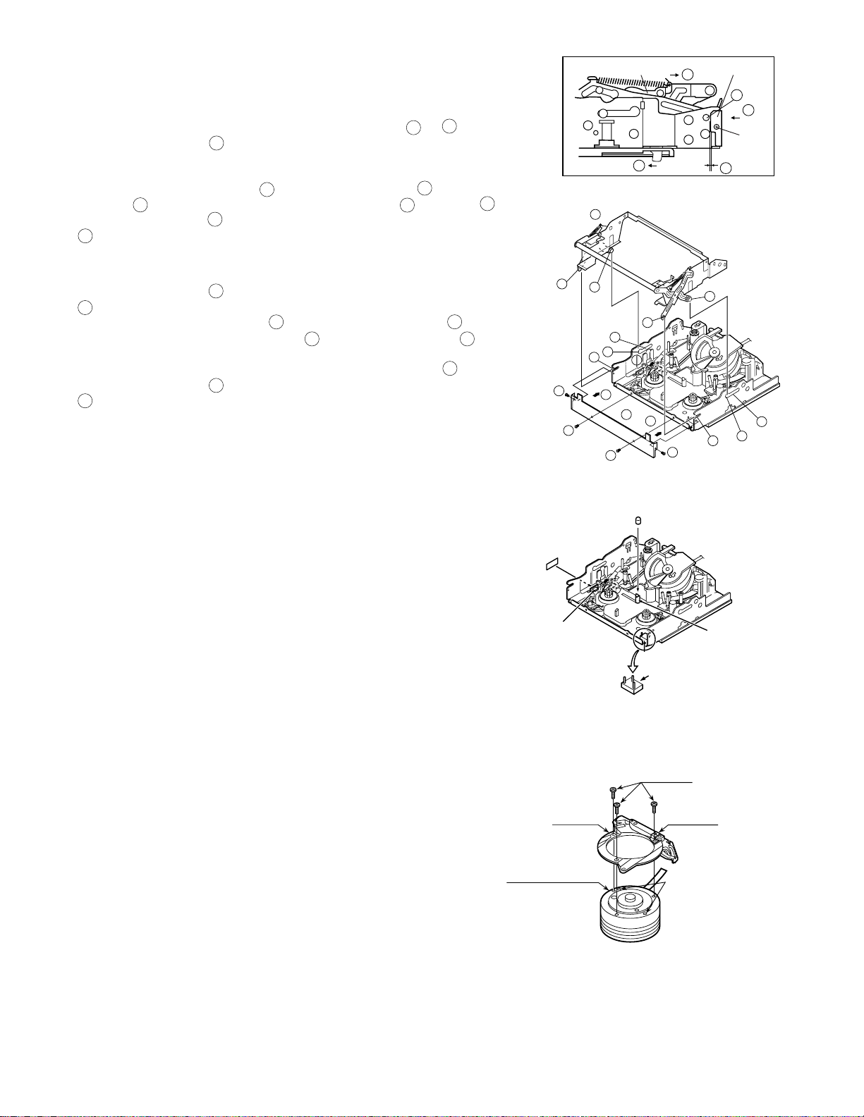
5-5-4. Drum and Drum base
*The upper drum and the lower drum have been replaced until now, respectively.
However, for this model, they are replaced as the upper/lower drum ass'y.
When replacing the drum, put on gloves and be careful not to damage it.
<Disassembling>
(1) Drum base (Common to both types)
Remove the three fixing screws to remove the drum base as shown in
the Figure 1.
<Reassembling>
Follow steps opposite to the drum disassembling method.
(1) Drum base
Adjust the positioning pins and secure the drum base with screws. (3 pcs.)
(2) Drum ass'y
Install the drum ass'y to the main chassis and secure it with screws. (3 pcs.)
(3) Tape guide
Adjust the positioning pins and secure the tape guide with a screw. (1 pc.)
Figure 1
20
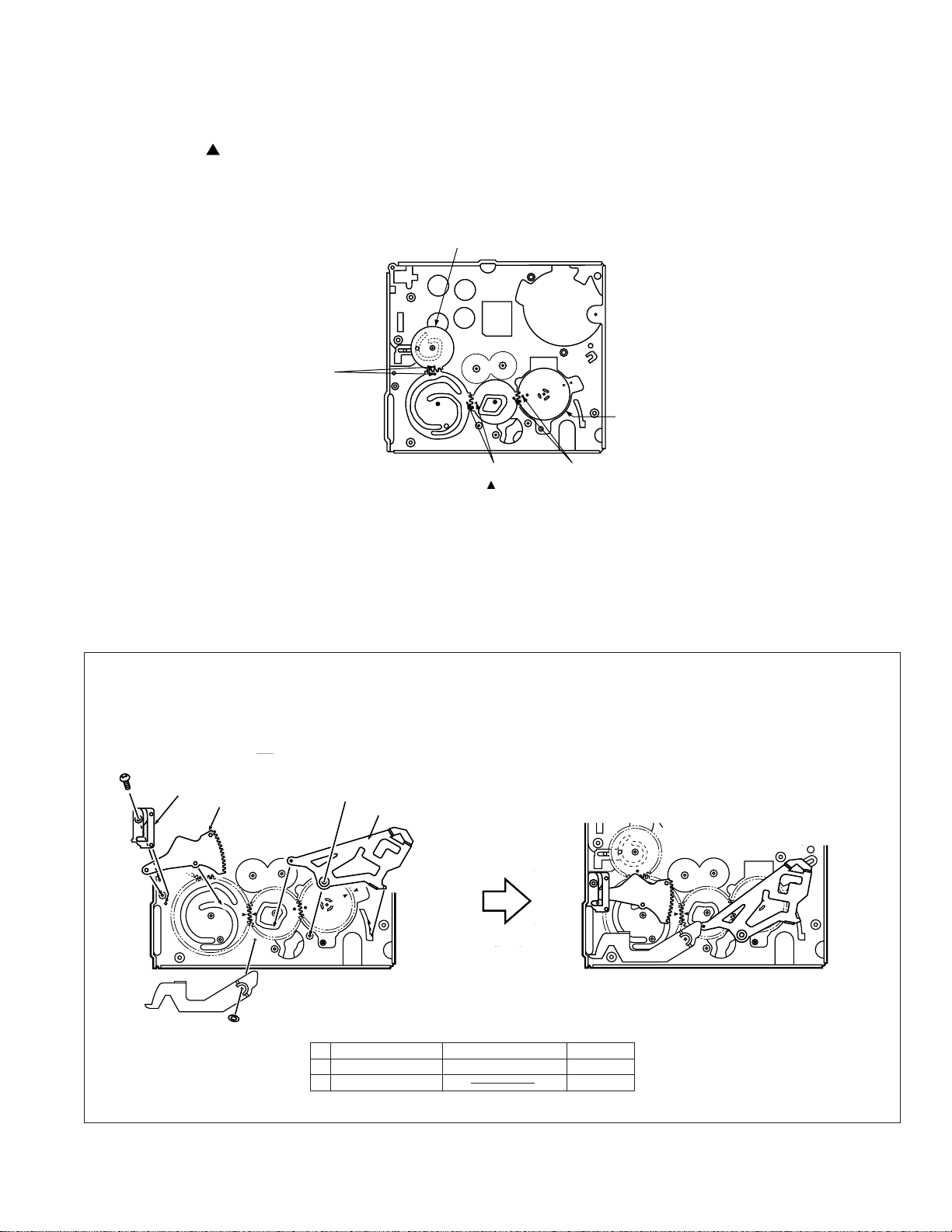
5-5-5. Phase matching
The phase of the following parts must be matched as
shown in the figure right.
(Ascertain that the marks and round holes align.)
(1) Lo relay gear (2) Main cam
(3) Sub-cam (4) Mode switch
Phase
alignment mark
(Round hole)
VL-AD260U
Lo relay gear
Mode switch
5-6. MECHANISM ASSEMBLING METHOD
(1) Adjust the phase of each part.
(2) Install screws and washers.
(3) Install the segment gear, T arm guide and the M-function
lever. Install the eject lever.
a
T arm guide
Segment gear
M-function lever
Move claw
to rear side.
Phase alignment
mark ( Mark)
Phase alignment mark
(Round hole)
Move claw to
rear side.
B
Item Tightening torque Quantity
a S Tight M1.4 x 3 70mN·m (0.7kgf·cm) 1
B ø0.8-ø3-t0.2 1
21
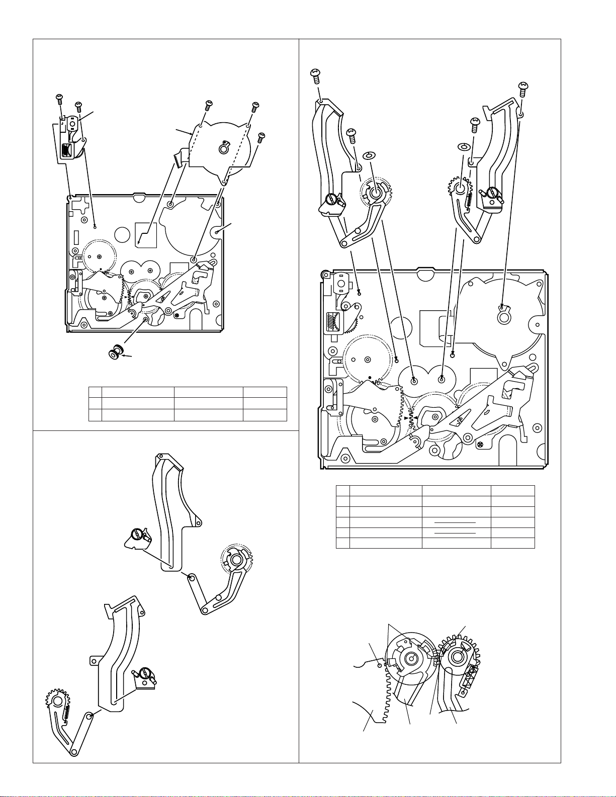
VL-AD260U
Make sure not deform the arm.
A
a
A
C
D
B
(4) Install the loading block assembly and the capstan motor.
(5) Install the drive gear. At this time, pay attention to the
direction of gear. (The small gear must be located in the
chassis side.)
a
A
Loading motor
Capstan motor
Move FF
downwards
a
a
a
Install the
motor under
this plate.
(7) Install the guide rail assembly taking care to position it
correctly.
(6) Install the guide rail assembly.
A S Tight M1.4 x 2.5 70mN·m 1
a S Tight M1.4 x 3 70mN·m 4
Insert the part in the
rail and slide it down.
Drive gear
Position the small gear of the drive
towards the chassis.
Item Tightening torque Quantity
Make sure not to
deform the arm.
Item Tightening torque Quantity
A S Tight M1.4 x 2.5 70mN·m 2
B S Tight M1.4 x 4 40mN·m 1
C ø0.8-ø3-t0.2 1
D ø2.1-ø5-t0.25 1
a S Tight M1.4 x 3 70mN·m 1
Align the marks on the parts.
Square Hollow Mark
Round Hole
Triangle Mark
Insert the part in the rail
and slide it down.
22
Segment gear
Edge A
Su arm Ass'y
T Lo arm Ass'y
VL-AD260U
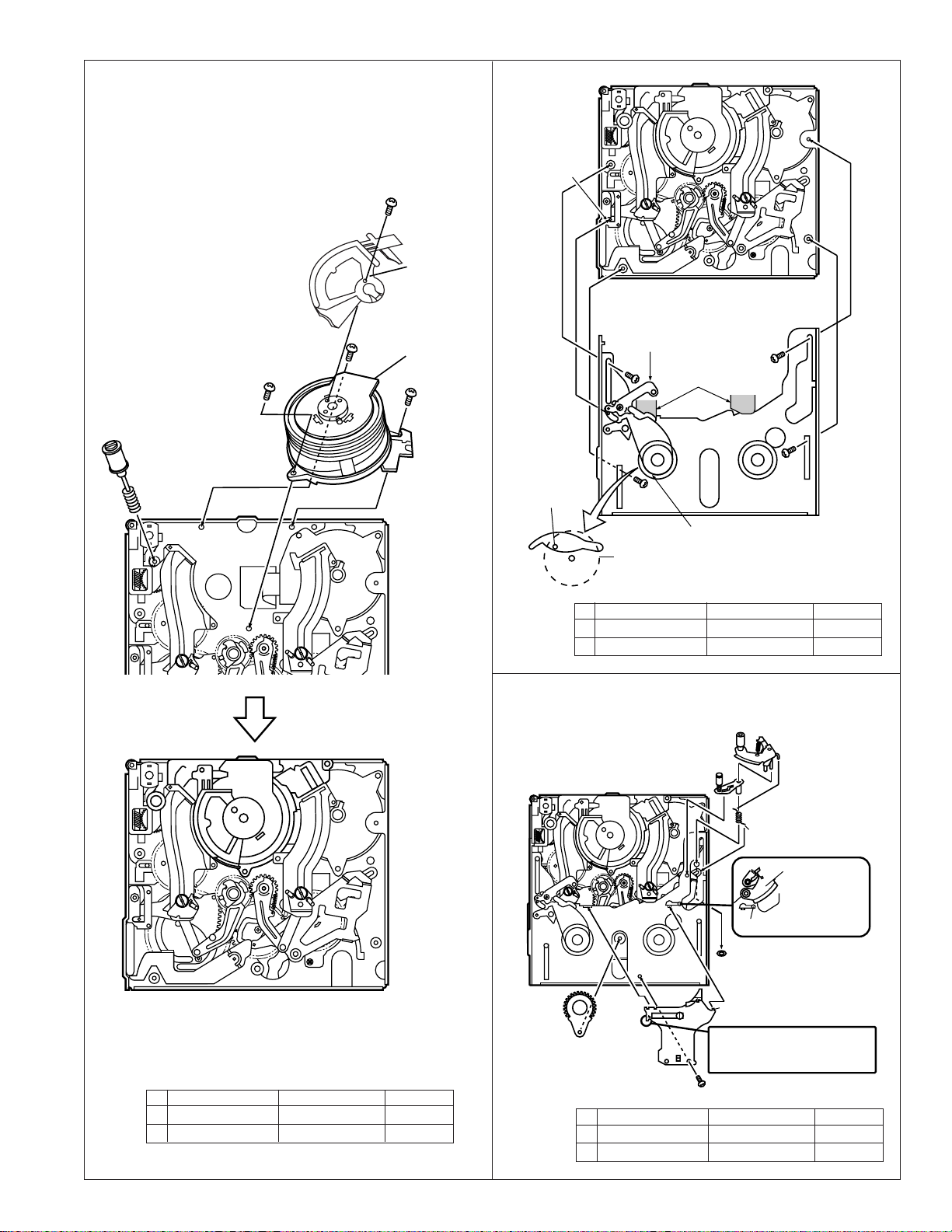
(8) Install the drum assembly in the chassis.
(9) Install the tape guide in the drum assembly.
(10) Install the Si roller.
A
A
Si roller
Roller spring
B
Tape guide
Drum assembly
A
(11) Install the slide chassis.
T arm guide
Slide this part towards the T arm.
Place the slide chassis
on the guide rail.
B
Main cam pin
B
Sup reel base
A
B
Insert the main cam pin into the
hole of cam of slide chassis.
Chassis drawing
Item Tightening torque Quantity
A M1.4 x 1.5 ø4 40mN·m 1
B M1.4 x 1.5 ø3.5 40mN·m 3
(12) Install in the following order: Tu guide lever spring, Tu guide
lever, pinch lever.
(13) Install the swing arm.
Pinch lever
(14) Install the right guide holder.
Tu guide lever
Attach to hook
Tu guide lever SPR
Attach to hook
Take care of position.
Pinch lever
The pinch lever
is positioned on
the stopper.
Stopper
B
Secure on back side
Claw
Swing arm
Claw
Take care not to bend the
tension band during assembly
or disassembly.
Item Tightening torque Quantity
A S tight M1.7 x L5.3 100mN·m 3
B S tight M1.7 x L2.5 60mN·m 1
A
Item Tightening torque Quantity
A S tight M1.4 x 2.5 70mN·m 1
B CW ø0.8-ø3-t0.2 70mN·m 1
23
VL-AD260U
6. ADJUSTMENT OF VCR AND CAMERA
6-1. INITIAL SETTING OF E2PROM IC
6-1-1. E2PROM data alterable ways
1) Set the switch of main body to CAM, and use the remote control (RRMCG0033TASA) for adjustment to turn on the adjustment
mode.
2) VCR adjustment address setting.
V ADJ
0000 “0000” is blinking
After an objective address was established, play key is pushed and set.
In addition, numerical change uses a “REW” or “FF” key.
3) VCR adjustment data setting.
V ADJ
0000 ## Value of “##” differs by an address.
After an objective data was established, “PLAY” key is pushed and set.
4) When data of other address are changed successively, push “STOP” key, and please repeat operation to 5) from 3).
5) When SW of the substance is turned into off, data are written to E
6-1-2. IC705 (E2PROM)
When the IC705 has been replaced, make the following settings and
adjustments.
1. Remove the backup battery (CR2025).
2. Turn power switch to CAMERA.
3. Setting up the V ADJ mode as follows.
* After press the CONTINUE key, press the VCR ADJ key on service
remote control (RRMCG0033TASA).
4. After setting the above data, clear the V ADJ mode and turn off the power
by pull out the battery pack or DC cable.
Neglect about 30 seconds after turned of power, because data of
address becomes effective after microcomputer is reset.
Now the setting of data is completion.
Adjustments to follow
Make the system controller servo, VCR, and LCD adjustments according
to their respective instructions.
2
PROM from systematic microcomputer.
Address Data
01 00
09 FF
02 01
0A FE
03 00
0B FF
04 00
0C FF
6-1-3. Camera adjustment
When the IC2 has been replaced, make the camera adjustment according
to its instructions.
All the camera adjustment data are written in the E2PROM provided on
the lens unit. Therefore, when the lens is replaced, the camera must be
adjusted again according to the camera adjusting procedure.
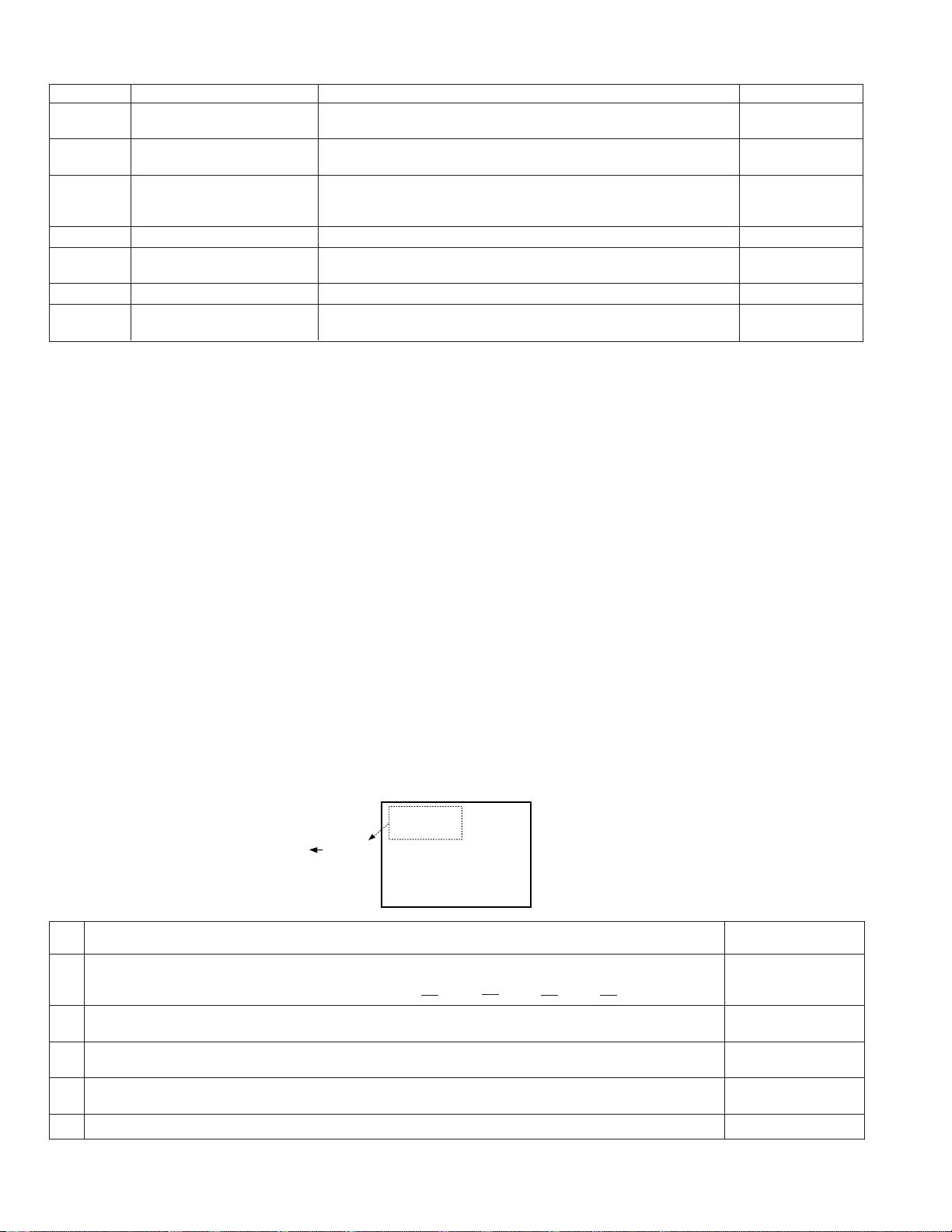
6-2. ADJUSTING THE Y/C, AUDIO AND LCD CIRCUITS ON MODELS WITHOUT A/V IN MODE
(A/V IN MODE SET-UP PRODUCE)
1) Set the switch of main body to CAM, and use the remote control (RRMCG0033TASA) for adjustment to turn on the adjustment
mode.
2) Set up the adjustment address (example : EE mode adjustment address 14). Once this address has been set up, the A/V IN mode (test
mode) is automatically brought and the images appear on the LCD display.
3) Now make the adjustments referring to the instruotions in the manual.
6-3. ADJUSTMENT OF VCR SECTION
6-3-1. Before starting the electric circuit adjustment
• Electric circuit adjustment becomes necessary, in most cases, when any of the wear mechanical parts or the video head has been
replaced. Before starting the electric circuit adjustment, be sure to check that the mechanical parts work well (i.e., the mechanical
parts have all been perfectly adjusted). In case a trouble or troubles are found in the electric circuitry, be sure to pinpoint the cause(s)
by using the measuring instruments described below. After locating the trouble spot(s), then proceed to repair, replacement or
adjustment. Do not change the positions of the controls when adequate measuring instruments are not available.
• In order to implement a higher-density, smaller machine, most of the electric circuit parts used on the Circuit Boards are of smallsized, surface-mounted type. For replacing part(s) as after-sales service, work with a soldering iron as speedily as possible. The
heat resistance of the surface-mounted components is poor, when compared with the larger-sized discrete parts used for television
sets and stationary decks, owning to their small sizes. Therefore, exercise due care to avoid long-time exposure of the pins of these
parts to the heat of the soldering iron which may possibly damage them. Such care should be exercised especially for chip-layer
capacitor replacement. It is advisable to use a temperature-controlled ceramic soldering iron (temperature at the tip: 250°C,
contacting time: less than 5 seconds).
24
VL-AD260U
< Adjusting the video/LCD section >
• Measuring instruments:
*Color monitor TV set *Oscilloscope *DC cable (AC adapter accessory)
*Digital voltmeter *Frequency counter *Video extension cables
*DC power supply *Signal generator *Vector scope
*Audio generator (CR oscillator) *AV output cable (accessory) *AC adapter
*Alignment tape (JiGWR5-5NSP) *Video recording tape
(JiGWR5-8NSE) (For Y/C, audio and servo adjustments)
6-3-2. Servicing the VCR section Adjustment
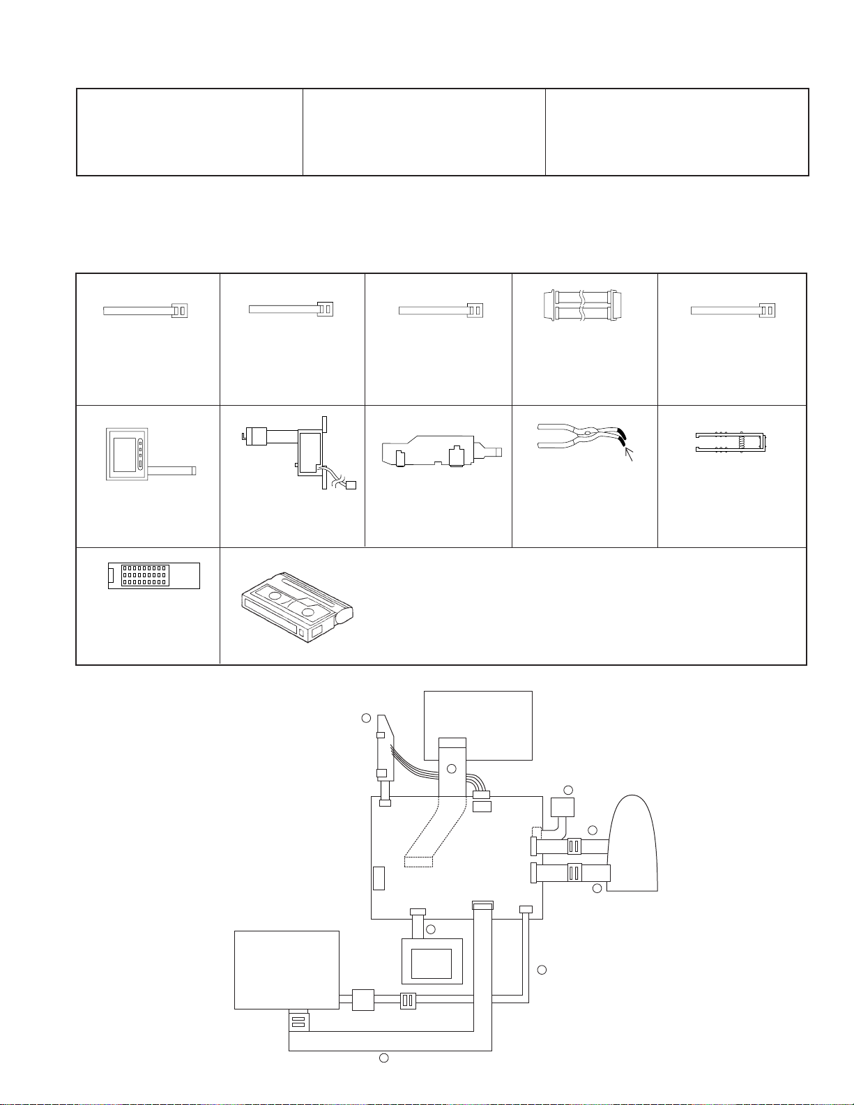
6-3-2-1. Typical connections
<Extension Cable etc.>
12345
Configuration
<Note: The entries of list> 1. Name 2. Part No. 3. Code
4. Note * Model, Uses Remarks
1. Extension Cable
Inverter~VCR (7pin
2. QCNW-1265TAZZ
3. AX
6
1. Operation Unit
2. QSW-Z0287TAZZ
3. AW
1. Service remote control
2. RRMCG0033TASA
3. BT
1. Extension Cable
Camera~VCR (20pin)
)
2. QCNW-1774TAZZ
3. BH
7
1. Battery Terminal Unit
2. QTANZ0146TAZZ
3. AK
1. Extension Cable
Camera~VCR (24pin)
2. QCNW-1382TAZZ
3. BD
1. Extension Cable
MECHA~VCR (70pin)
2. QCNW-1534TAZZ
3. BS
8
insulating sleeve
1. AV Jack Unit
2. RUNTK0352TAZZ
1. Connector fitting and
withdrawing extractor
3. AS
· Alignment Tape
JiGWR5-5NSP (NTSC) .... Normal 8 TAPE (MONO)
JiGWR5-8NSE (NTSC) ...Hi8 TAPE (MONO)
* Y/C Audio Alignment
AV JACK
UNIT
8
DC-IN
MECHA UNIT
1. Extension Cable LCD~
VCR (24pin)
2. QCNW-1382TAZZ
3. BD
1. Connector fitting and
withdrawing tweezers
2. 9EQPiNSET06GE
3. BR
LCD UNIT
AV OUT
INVERTER
5
6
25
4
VCR UNIT
7
2
CAMERA
UNIT
3
1
VL-AD260U
• Types of test modes
TEST No. Sensor on/off
Title
1 Sensors off All sensors but the cassette controller switch, dew sensor and
battery sensor stay off.
3 Automatic battery sensor Battery sensor’s input voltage put in memory.
adjustment
4 Battery adjustment error Battery sensor’s adjustment errors are displayed at the right of All sensors on
display the “past errors” area. All but sensors
5 PASS mode Track shift mode (1/4 shift) All sensors on
6 Camera adjustment mode Camera adjustment mode [VCR
7 VCR adjustment mode VCR adjustment mode
8 Automatic switching point Play standard tape and call this mode. Switching point is
adjustment (STOP ADJ) automatically adjusted.
1 When the battery adjustment mode is selected from the camera adjustment mode with a cassette with the erase protection tab,
the VCR is automatically put in the REC mode.
• Below discussed are these seven test modes.
1 [TEST No. 1] Sensors off mode
All the sensors, except for the cassette controller switch, dew sensor and battery sensor, stay off. This enables
to bring the VCR in the loading mode without tape. The VCR/camera performance can now be checked with no
tape inside.
2 [TEST No. 3] Automatic battery alarm adjustment
Used to automatically adjust the voltage level which makes the “battery” appear on the LCD display.
3 [TEST No. 4] Battery alarm check/error display
• The difference between the preset battery alarm voltage and the current supply voltage is displayed as follows.
• A past error is displayed at the right of the current battery alarm error.
4 [TEST No. 5] PASS mode
Used to adjust the tape travelling condition. The tracking is shifted by 1/4 from the center to make the tape
running-related RF envelope fluctuations easier to observe.
5 [TEST No. 6] Camera adjustment mode
Used to adjust the camera section. (For details, see Servicing the Camera Section.)
6 [TEST No. 7] VCR adjustment mode
Used to adjust the VCR section. (For details, see Servicing the VCR Section.)
7 [TEST No. 8] Automatic switching point adjustment
Used to automatically adjust the playback switching point. (For details, see Automatic Adjustment of the
Playback Switching Point.)
Contents
on
interrupted]
6-3-2-2. Setting up the VCR section adjustment mode (camera section adjustment)
• Select adjustment items by using addresses. Rewrite the adjustment data to change the settings.
Below shown the adjustment procedures and on-screen display.
Enlarged view
(CAM ADJ) camera
V ADJ VCR, LCD
0000 00
(Address) (Data)
Procedural steps
1 Turn up or down the flashing hexadecimal number with the FF or REW key to select the V ADJ
address of a desired adjustment item. (Initial address: 00H)
Note: The addresses change as follows. 01FE 01FF 0000 0001 0002
2 Press the PB key to read the data of the selected address. V ADJ
3 Turn up or down the data setting with the FF or REW key. The data display starts flashing. V ADJ
4 Press the PB key again to write the data setting into the selected address. V ADJ
5 Press the STOP key in the above step 2 or 4, and the screen returns back to the step 1. V ADJ
When the FF or REW key is held down for 0.3 second or longer, the address selection is repeated in cycles of 100 msec. The data
setting changes by ± 4 by holding the key down for 2 seconds or longer.
VCR ADJ
0000 00
T-07
Display
( : flashing)
002C A3
002C
002C 72
26

VL-AD260U
6-3-2-3. Battery shut-off voltage adjusting method
1) Supply power to the main unit, using the variable-voltage DC power supply (range of 2.5V to 5.0V).
2) Set the CAM/OFF/VCR SW to CAM to switch to the camera mode.
3) Load a recordable tape and set the main unit to CAM REC. PAUSE.
4) Set the main unit to TEST mode No. 3, and start recording.
5) Measure voltage between TL2911(+) and TL2914(GND), and adjust the supply voltage to 3.1V.
6) The adjustment is complete if "BATTERY" is displayed on the monitor screen for a second when the PLAY key of operation unit
is pressed.
7) The adjustment is regarded as proper if the auto shut-off is actuated after the warning is displayed when the TEST mode is
cancelled.
* In case of automatic adjustment of shut-off voltage, adjustment is impossible if voltage is above 3.1V ± 0.2V.
If the adjustment is made at 2.9V or below, the low-voltage operation may become unstable.
•Type of test modes
<Procedues>
To adjust the camera section of this machine, the remote control for servicing (RRMCG0033TASA) is used.
Press the "CONTINUE" key → "TEST SEL", this will show [T-01] on the LCD OSD, (01:flashing), and select the below TEST No. with
"FF" or "REW" key and set with "PLAY" key.
Same procedures of adjustment from now on.
Use the SW2 thru SW9 switches on the adjustment tool to select the following test modes.
TEST No. Title
1 Sensors off All sensors but the cassette controller switch, dew sensor and
battery sensor stay off.
2 Mechanism adjustment 1 Automatic SP/LP detection prohibited All sensors on
mode 2 Different-mode detection prohibited
3 ATF sampling limited to center
3 Automatic battery sensor Battery sensor’s input voltage put in memory.
adjustment
4 Error display Past errors appear on the counter display of the viewfinder. All sensors on
Battery adjustment error Battery sensor’s adjustment errors are displayed at the right of the All but sensors
display “past errors” area. on
5 PASS mode Track shift mode (1/4 shift) All sensors on
6 Camera adjustment mode Camera adjustment mode [VCR
7 VCR adjustment mode VCR adjustment mode
8 Automatic switching point Play standard tape and call this mode. Switching point is
adjustment (STOP ADJ) automatically adjusted.
1 When the battery adjustment mode is selected from the camera adjustment mode with a cassette with the erase protection tab,
the VCR is automatically put in the REC mode.
Contents
Sensor on/off
interrupted]
27
VL-AD260U
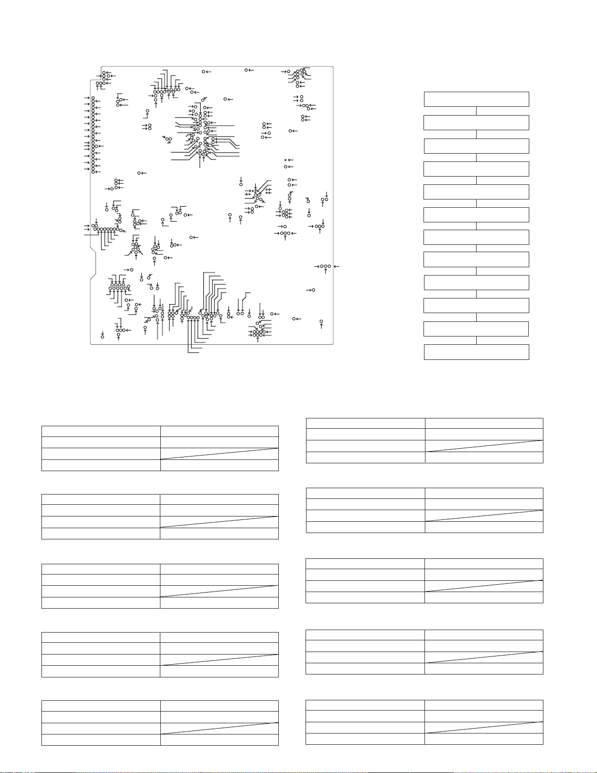
6-3-3. Adjusting the VCR circuit
• Test Points on the Video Circuit Board
TL5711
TL5713
TL5715
TL5717
TL5719
TL5721
TL5723
TL5725
TL5726
TL704
TL706
TL708
TL710
TL3817
TL3826
TL3814
TL5703
TL5707
TL7450
TL3815
TL3818
TL3803
TL5712
TL5714
TL5716
TL5718
TL5720
TL5722
TL5724
TL7448
TL7453
TL3808
TL3820
TL3819
TL3821
TL1800
TL965
TL5727
TL705
TL707
TL709
TL711
TL748
TL3823
TL5702
TL5704
TL5705
TL5706
TL3812
TL3813
TL3804
TL3805
TL961
TL3810
TL3811
TL910
TL901
TL5701
TL7403
TL3809
TL964
TL5708
TL715
TL714
TL712
TL912
TL3807
TL3822
TL3824
TL5709
TL5710
TL703
TL7433
TL7415
TL3816
TL3827
TL3825
TL1233
TL1234
TL960
TL9401
TL701
TL3801
TL9901
TL3800
TL9403
TL9402
TL727
TL749
TL7405
TL800
TL3806
TL801
TL802
TL963
TL1231
TL1801
TL9405
TL9404
TL7425
TL718
TL949
TL948
TL3802
TL1232
TL702
TL7409
TL946
TL7443
TL9902
TL1230
TL1235
TL7402
TL7408
TL7438
TL7412
TL7422
TL7413
TL728
TL945
TL1228
TL1229
TL9406
TL7436
TL947
TL7441
TL1226
TL7416
TL7418
TL7420
TL7417
TL7429
TL7447
TL942
TL9903
TL1225
TL9407
TL9408
TL7404
TL7406
TL7407
TL743
TL1222
TL9409
TL7446
TL7440
TL7414
TL941
TL1227
TL9412
TL742
TL1223
TL1224
TL1221
TL9413
TL720
TL1220
TL1219
TL7423
TL940
TL7424
TL7411
TL1217
TL1218
TL7410
TL7444
TL1211
TL1216
TL9414
TL7452
TL7449
TL7445
TL7439
TL7437
TL7435
TL7434
TL7427
TL1212
TL1215
TL943
TL1213
TL7431
TL7430
TL1214
TL1205
TL726
TL944
POWER CIRCUIT ADJUSTMENT METHOD
Æ Input 7V from DC Jack, and set the power switch to the camera side.
` Don't fail to fix the back light unit before adjusting them.
1. Checking of CAM 15V
Ascertain that the digital voltmeter indicates 15V ± 0.45V.
Measuring instrument Digital voltmeter
Measuring terminal TL930
Adjustment address
Standard 15V ± 0.45V
2. Checking of P-CON 4.9V
Ascertain that the digital voltmeter indicates 4.9V ± 0.1V.
Measuring instrument Digital voltmeter
Measuring terminal TL901
Adjustment address
Standard 4.9V ± 0.1V
3. Checking of P-CON 3.3V
Ascertain that the digital voltmeter indicates 3.3V ± 0.1V.
Measuring instrument Digital voltmeter
Measuring terminal TL910
Adjustment address
Standard 3.3V ± 0.1V
4. Checking of P-CON 3.1V
Ascertain that the digital voltmeter indicates 3.1V ± 0.1V.
Measuring instrument Digital voltmeter
Measuring terminal TL911
Adjustment address
Standard 3.1V ± 0.1V
5. Checking of DSP 2.5V
Ascertain that the digital voltmeter indicates 2.5V ± 0.1V.
Measuring instrument Digital voltmeter
Measuring terminal TL912
Adjustment address
Standard 2.5V ± 0.1V
TL5734
TL5730
TL5732
TL5742
TL2703
TL2704
TL1210
TL1209
TL1208
TL1203
TL1207
TL7451
TL7442
TL7432
TL5743
TL724
TL1204
TL2912
TL2913
TL2916
TL7421
TL7419
TL7428
TL7426
TL911
TL5741
TL5728
TL1202
TL2915
TL1454
TL1201
TL2708
TL2705
TL2709
TL2717
TL2711
TL2713
TL1971
TL607
TL3612
TL3611
TL3610
TL3609
TL3608
TL606
TL602
TL603
TL605
TL5740
TL5739
TL5738
TL5731
TL5729
TL5733
TL733
TL5736
TL2707
TL5737
TL2908
TL2706
TL1972
TL1970
TL2911
TL1206
TL2914
TL2714
TL713
TL2702
TL2701
TL2710
TL2718
TL2904
TL2923
TL920
TL2715
TL2919
TL2907
6. Checking of DSP 1.9V
7. Checking of LCD 13.5V
8. Checking of LCD 7V
9. Checking of LCD -15.2V
10.Checking of CAM -8V
6-3-3-1. Adjusting the power
circuit
TL3607
TL3601
TL3602
TL608
TL604
TL3604
TL3603
TL610
TL609
TL2909
TL2922
TL2906
TL2905
TL2920
TL2918
TL2910
Ascertain that the digital voltmeter indicates 1.8V ± 0.1V.
Measuring instrument Digital voltmeter
Measuring terminal TL920
Adjustment address
Standard 1.85V ± 0.15V
Ascertain that the digital voltmeter indicates 13.2V ± 0.2V.
Measuring instrument Digital voltmeter
Measuring terminal TL932
Adjustment address
Standard 13.2V ± 0.5V
Ascertain that the digital voltmeter indicates 7V + 0.4/-0.5V.
Measuring instrument Digital voltmeter
Measuring terminal TL933
Adjustment address
Standard 7V + 0.4/-0.5V
Ascertain that the digital voltmeter indicates -15.2V ± 1V.
Measuring instrument Digital voltmeter
Measuring terminal TL938
Adjustment address
Standard -15.2V ± 1V
Ascertain that the digital voltmeter indicates -8V ± 0.5V.
Measuring instrument Digital voltmeter
Measuring terminal TL935
Adjustment address
Standard -8V ± 0.5V
a) POWER CIRCUIT ADJUSTMENT
PROCEDURE
Turn on power
û
1. Check CAM 15V
2. Check P-CON 4.9V
3. Check P-CON 3.3V
4. Check P-CON 3.1V
5. Check DSP 2.5V
6. Check DSP 1.9V
7. Check LCD 13.5V
8. Check LCD 7V
9. Check LCD -15.2V
10. Check CAM -8V
û
û
û
û
û
û
û
û
û
û
Æ Turn off power.
28
VL-AD260U
286mVp-p
6H
3H 3H
V sync signal
6H
3H 3H
V sync signal
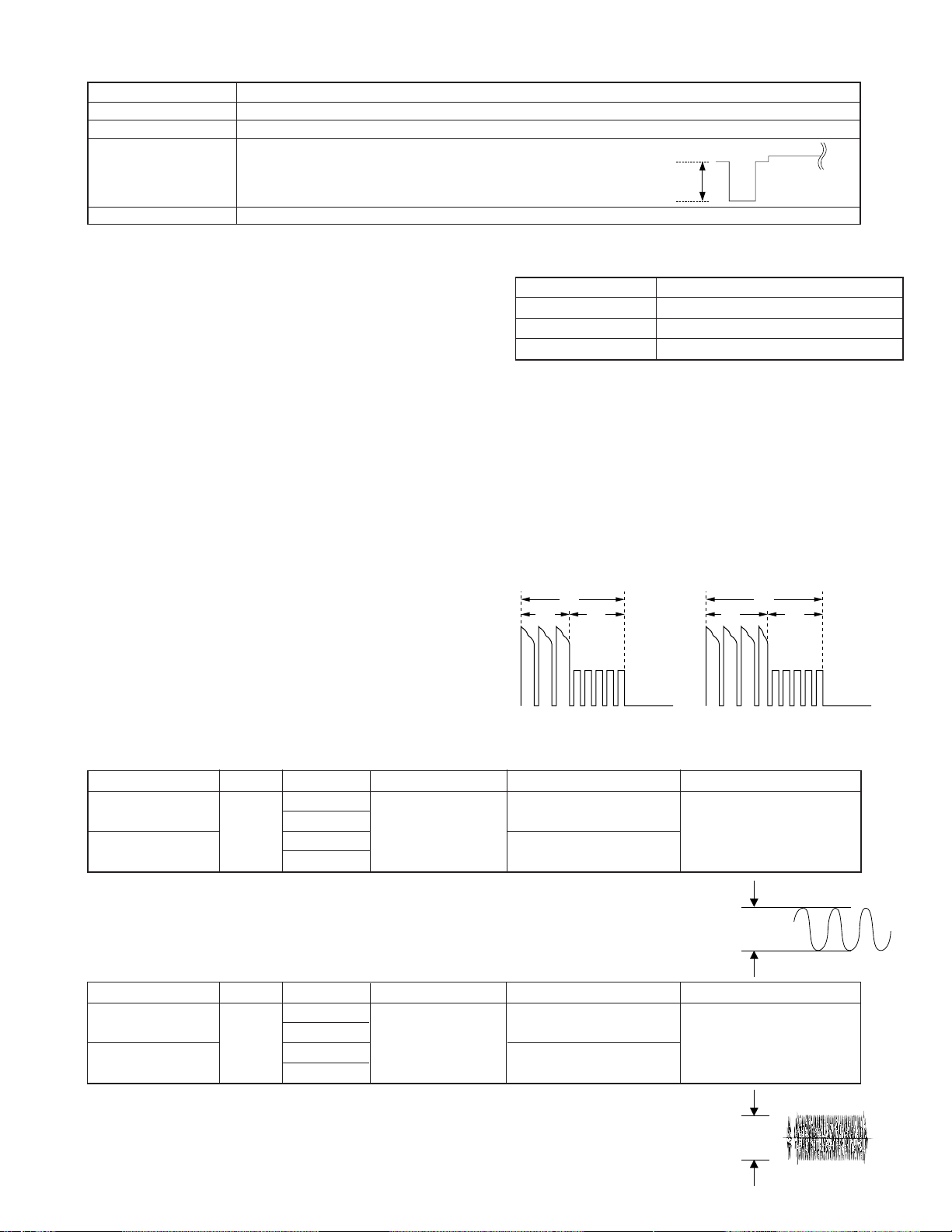
6-3-3-2. Adjustment of Video Out circuit
Measuring point TL3602 (VIDEO OUT)
Address 036
Mode VCR
Adjusting method 1) Set the data of address 036.
2) TL3602: Oscilloscope
3) Adjust P-P of TL3602 becomes spec.
SPEC: SYNC LEVEL → 286mVp-p (Terminated in 75Ω)
Adjusting standard 286±10mVp-p
6-3-4. Adjustment of system controller and servo circuit
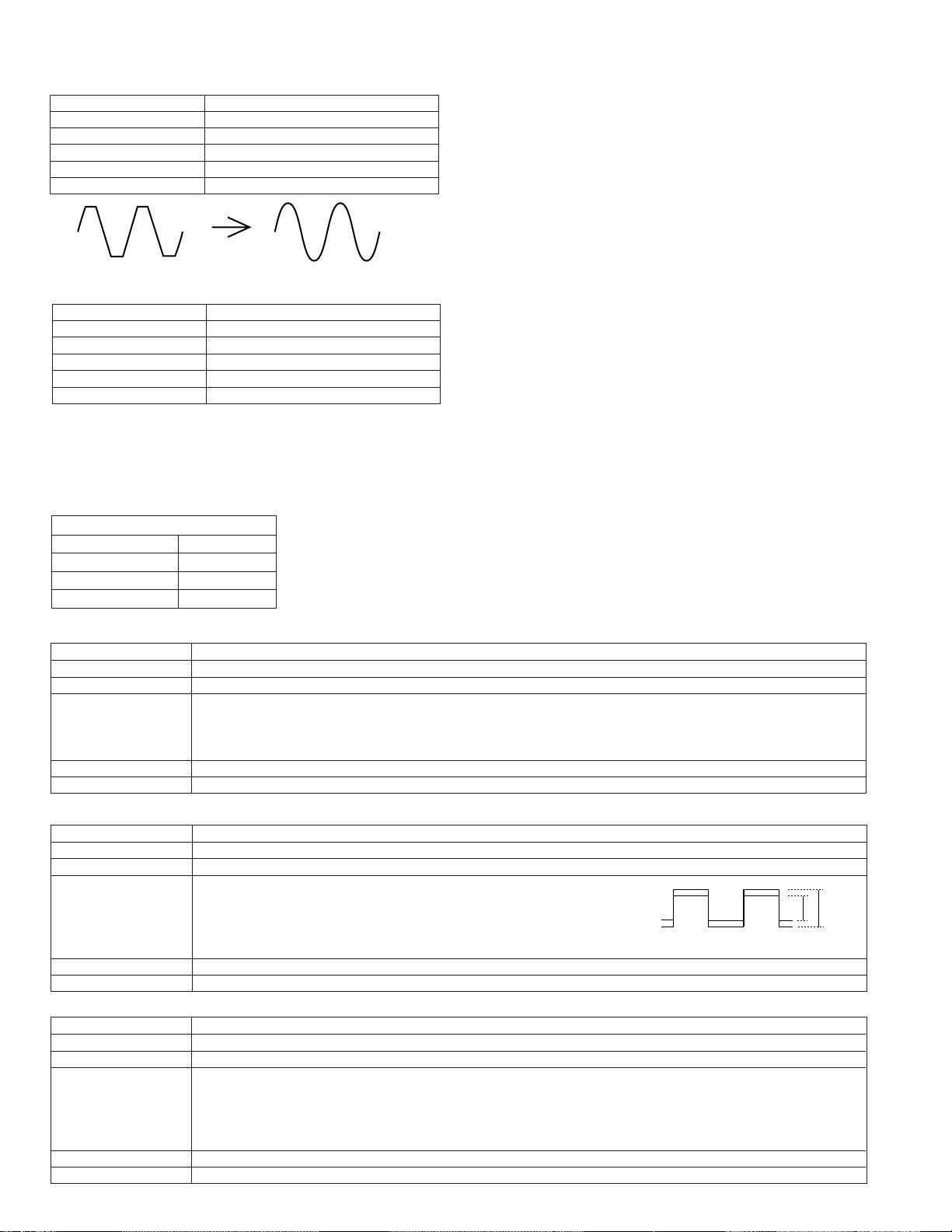
6-3-4-1. Adjustment of playback switching point
b) CHARGING CIRCUIT ADJUSTMENT PROCEDURE
1)Play back the alignment tape (JiGWR5-5NSP)
2)Press the “CONTINUOUS PUSH” and “TEST MODE SELECTION” of adjustment remote controller to set the test mode.
Measuring instrument
Mode Playback
Adjustment address 30h
Tape Alignment tape (JiGWR5-5NSP)
(At this time the numeral of “TEST01” blinks.)
3)Using the “FF” and “REW” keys, select “TEST08”, and press the playback key to set the SW-P adjustment mode.
4)When the adjustment is completed, "HSWP" is displayed and the tape is ejected.
When the adjustment is not proper, "NG" is displayed in the red frame of the unit.
Only in the case when the satisfactory result was not obtained by the adjusting method described above, perform the following
adjustment.
1)Connect each signal to the oscilloscope.
1ch: VIDEO OUT ..... TL3602
2ch: H-SW-P ............ TL7417
GND: GND ................. TL1454
2) Play back the alignment tape (JiGWR5-5NSP)
3)Press the “CONTINUOUS PUSH” and “VCR ADJUSTMENT” of adjustment remote controller to set the VCR adjustment mode.
4)Select the address 30h, set the sync slope of oscilloscope to (–),
adjust the data with “REW” and “FF” so that the interval between
the trigger point and the V sync signal is set to 6H, and fix the data
with the “PLAY” button. (See Figure 6.1.1.)
5)Then, set the sync slope to (+), and ascertain that the interval
between the trigger point and the V sync signal has been set to 6H.
(See Figure 6.1.2.)
6)Keep the STOP key pressed for about 3 seconds to exit from the
adjustment mode.
Figure 6.1.1
Oscilloscope
Figure 6.1.2
6-3-5. Adjustment of Head Amp circuit
1. Y recording current adjustment
Mode Address Measuring point Adjustment standard Measuring instrument
REC Y current
adjustment (Hi-8)
REC Y current
VCR
STOP
adjustment (Nor 8)
(1) Enter the VCR STOP mode.
(2) Select the above applicable address with the adjustment remote control.
(3) Measurement signal is output to TL9413.
(4) Adjust the amplitude so as to get the adjustment standard value at TL9413(Sig) and TL9414(Gnd).
3F ME 130±5mVP-P
40 MP 95±5mVP-P
41 ME 125±5mVP-P
TL9413 (Sig)
TL9414 (Gnd)
42 MP 120±5mVP-P
Oscilloscope
Standard value
2. C recording current adjustment
Mode Address Measuring point Adjustment standard Measuring instrument
REC C current
adjustment (Hi-8)
REC C current
adjustment (Nor 8)
VCR
STOP
43 ME 115±5mVP-P
44 MP 105±5mVP-P
45 ME 135±5mVP-P
TL9413 (Sig)
TL9414 (Gnd)
46 MP 120±5mVP-P
(1) Enter the VCR STOP mode.
(2) Select the above applicable address with the adjustment remote control.
(3) Measurement signal is output to TL9413.
(4) Adjust the amplitude so as to get the adjustment standard value at TL9413 (Sig) and TL9414 (Gnd).
29
Oscilloscope
Standard value
VL-AD260U
6-3-6. Adjustment of audio circuit
1. Adjustment of filter f0
Measuring instrument Oscilloscope
Mode PB
Input signal (tape) JiGWR5-5NSP
Measuring terminal TL605/AUDIO OUT
Adjustment address 33
Set value Clear the waveform
Audio Check
Checking of self-recording/playback
Measuring instrument Valve Voltmeter (oscilloscope)
Mode REC →PB
Input signal (tape) 400 Hz, -8 dBs (872 mVp-p)
Measuring terminal Audio IN/OUT
Adjustment address —
Set value -8 dBs ± 4 dBs (580 to 1370 mVp-p)
1) Set the alignment tape (JiGWR5-5NSP).
2) Using the adjustment remote controller (RRMCG0033TASA),
set the VCR adjustment mode, and set the address “33” with
the operation switch (FF/REWIND key).
3) Play back the standard tape.
4) Using the operation switch (FF/REWIND key), make an
adjustment so that the most clear playback waveform is
obtained on TL605.
5) Press the operation switch (PLAYBACK key) to write the
data.
6) Press the operation switch (STOP key) to exit from the
address “33”.
(The address “33” blinks.)
1) Input the audio signal (400Hz, -8dBs) into the Audio line IN/
OUT terminal, and record.
2) Connect the valve voltmeter (oscilloscope) to the Audio line
IN/OUT terminal.
3) Play back the record, and ascertain that the output waveform
level is -8 dBs ± 4 dBs (580 to 1370 mVp-p on the oscilloscope).
4) If there is any deviation from the specified value, perform
adjustment again as stated in items 1) above, and check again
the self-recording/playback level.
6-3-7. Adjustment of LCD display circuit
Adjustment procedures and connections are the same as with the VCR section. (Refer to item 6-3-3)
1. Inverter input Voltage Setting
VCR ADJ
Address Data(3.5 type)
50 95
51 90
52 74
2. Dac full-Scalle adjustment
Measuring point TL1801 (G-OUT)
Address 039
Mode VCR
Adjusting method 1) Set the data of address 082 changed to 80, address 0A2 changed to 00, address 0A5 changed to 80.
2)Connect TL3804 to P-CON 3.1V.
3)Connect the Digital voltmeter to TL801 and adjust the DC volt.
4)Set the data of address 082 changed to 40, address 0A2 28. (Restore)
Adjustment standard 0.78V ± 10mV
Remarks ———————
3. R-W/B adjustment
Measuring point TL3814 (LCD-VG) TL3813 (LCD-VR)
Address 090
Mode VCR
Adjusting method 1) Set the data of address 082 at the address 80.
2)TL3814 (LCD-VG): Oscilloscope CH1
TL3813 (LCD-VR): Oscilloscope CH2
3)Adjust P-P of TL3813 becomes bigger 0.15V than TL3814.
4)Set the data of address 082 at the address 40. (Restore)
Adjustment standard ±0.1Vp-p
Remarks ———————
4. B-W/B adjustment
Measuring point TL3814 (LCD-VG) TL3815 (LCD-VB)
Address 092
Mode VCR
Adjusting method 1)Set the data of address 082 at the address 80.
2)TL3814 (LCD-VG): Oscilloscope CH1
TL3815 (LCD-VB): Oscilloscope CH2
3)Adjust P-P of TL3815 become bigger 0.1V than TL3814.
4)Set the data of address 082 at the address 40. (Restore)
Adjustment standard ±0.1Vp-p
Remarks ———————
G R
30
 Loading...