

Page 1
SERVICE MANUAL
The UP-P07DP is the optional POLE DISPLAY UNIT of ER-A750.
POLE DISPLAY
MODEL UP-P07DP
CHAPTER 1. GENERAL
The UP-P07DP is a unit that modifies the rear display (standard on
the ER-A750) to the pole display.
CHAPTER 2. INSTALLATION
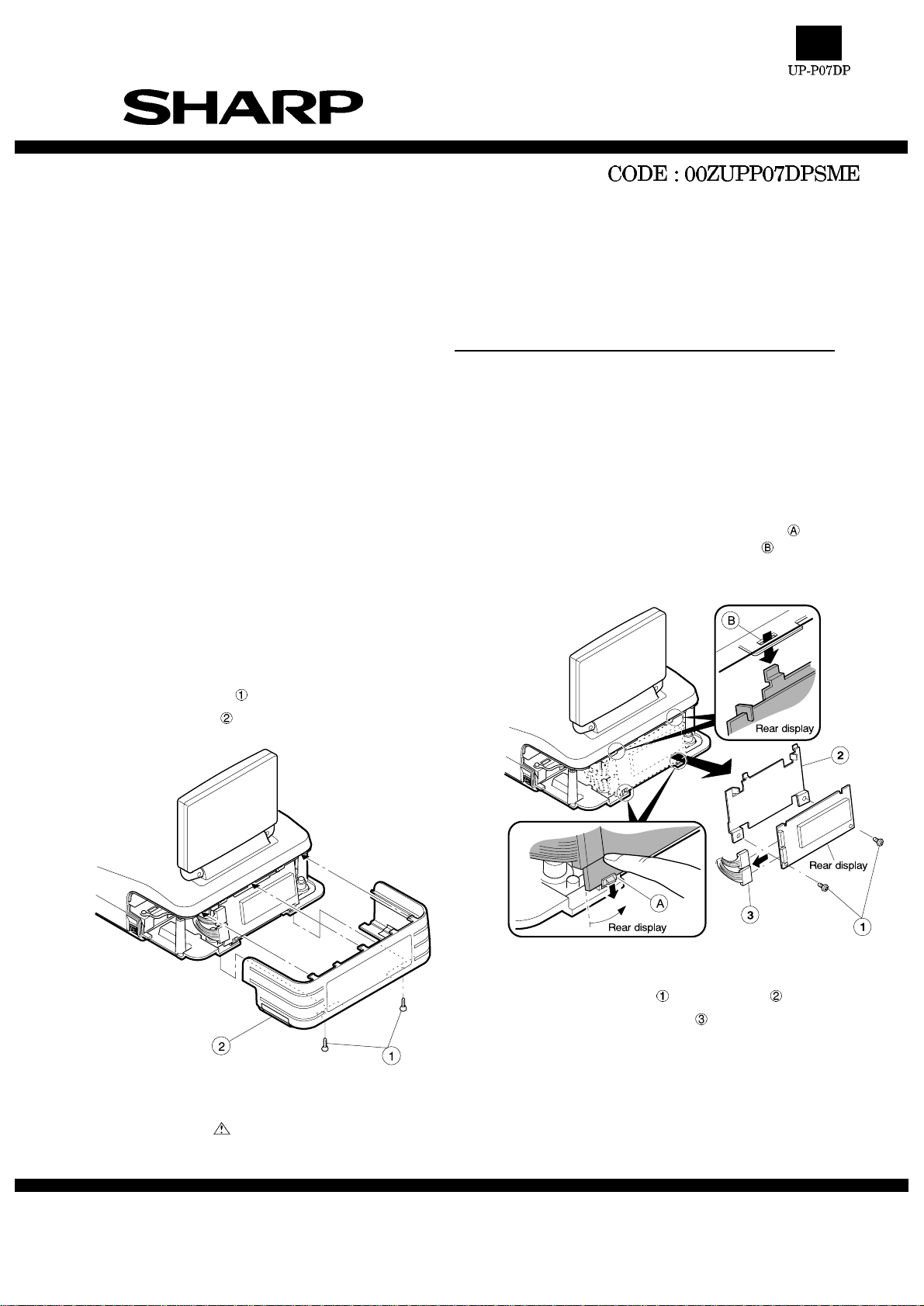
1. Removing the Rear cover
1) Removing the two screws fixed on the lower cabinet.
2) Remove the rear cover
2. Removing the Rear display PWB
1) Pull the lower cabinet pawl in the direction of to release the
lock, and pull out the rear display in section
.
2) Remove the two screws
3) Disconnect the two connwctors
Parts marked with " " are important for maintaining the safety of the set. Be sure to replace these parts with specified
ones for maintaining the safety and performance of the set.
SHARP CORPORATION
fixed on the angle .
This document has been published to be used
for after sales service only.
The contents are subject to change without notice.
Page 2
>>>>> USE FONT <<<<<
Helvetica/ Helvetica-Condensed/ Century-Schoolbook/ Symbol & OriginalFonts: (RingWorld2/RingFont2/Pa
Symbol/PartsCod)
- - - - - - - - - - - - - - - - - - - - - - - - - - - - - - - - - - - - - - - - - - - - - - - - - - - - - - -
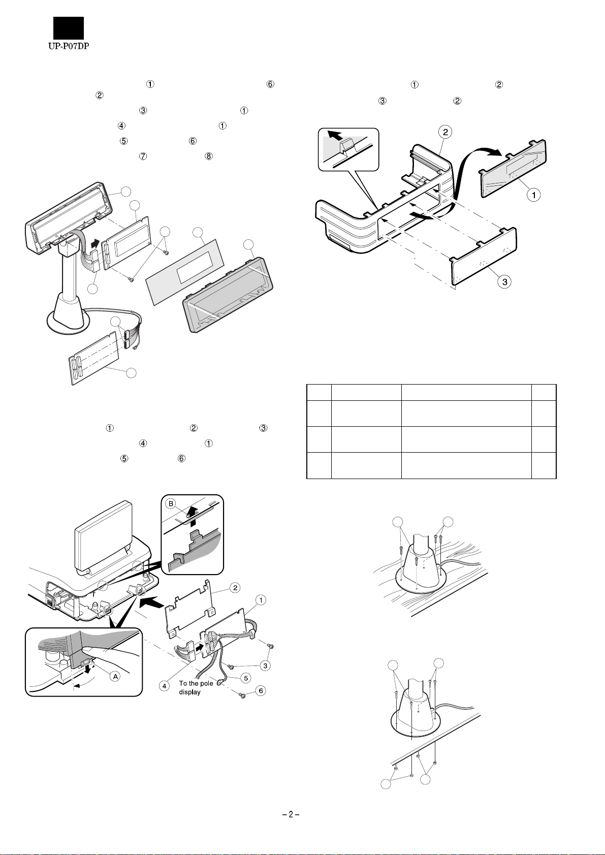
3. Install the rear Rear display PWB to the Pole unit
1) Install the Rear display PWB to the Angle of the Pole unit
with two screws .
2) Connect the two connectors
3) Attach the Blind sheet
4) Install the Display filter
5) Connect the two connectors to the I/F PWB .
3
7
to the Rear display PWB .
to the Rear display PWB .
to the Pole unit.
6
1
2
8
4
5
5. Change the Display filter
1) Remove the Display filter from the Rear cover .
2) Install the Panel
to the Rear cover .
6. Replacing the Rear cover
1) Install the Rear cover in the reverse order of removing.
7. Fasting on the table
1) Secure the Base cabinet using the screw.
4. Install the I/F PWB to the ER-A750
1) Install the I/F PWB to the Display angle with two screws .
2) Connect the two connectors
3) Fix the Grounding wire
to the I/F PWB .
with a screw on the Option angle.
No. NAME USE Q’ty
(1) Screw (M4 x 16) Securing the UP-P07DP to the
wooden table
(2) Screw (M4 x 20) Securing the UP-P07DP to the
metal table
(3) Nut Securing the UP-P07DP to the
metal table
Wooden table:
1 1
Metal table:
2
2
4
4
4
3
3
Page 3

CHAPTER 3. I/F PWB LAYOUT
Page 4

UP-07DPW
■ Parts guide
1Exteriors
NO. PARTS CODE
QCNW-2014BHZZ BG
3
PSHEP6856BHZZ AF
4
LANGK7631BHZZ AL
5
GCABR7857BHZA AY
6
LANGK2881BHZZ AR
7
XJPSD30P06000 AA
8
XHBSD30P04000 AA
9
LX-BZ6789BHZZ AP
10
GCABA7859BHZZ AQ
11
XUPSD26P06000 AA
12
GCAB-7259BHZZ AN
13
NSFTP6657BHZZ AR
14
GCABB7858BHZZ AS
15
XJBSD30P08000 AA
16
XJPSD30P12X00 AB
19
LANGK7626BHZZ AY
20
LHLDW6812BHZZ AC
21
LX-BZ6782BHZZ AA
22
1Exteriors
PRICE
RANK
NEW
PART
MARK
RANK
N C Relay shield cable
C Display sheet
C Tilt angle
N D Display cabinet
N C Display angle
CScrew (3´6) [DIS CAB+DIS FILTER]
CScrew (3´4) [SHIELD ANGLE]
CScrew
D Tilt cabinet
C Screw (2.6´6) [POLE+RATCHET]
D Ratchet
C Pole
D Base cabinet
CScrew (M3´8) [BASE CAB+RATCHET]
CScrew (3´12X) [BASE CAB+BASE ABGLE]
C Base angle
C Holder (4N)
CScrew (3´8KS) [HOLDER]
DESCRIPTION
4
5
7
8
12
15
6
8
10
12
9
13
14
16
11
14
3
21
22
19
19
– 1 –
20
19
RCP00308
Page 5

2 Packing material & Accessories
PRICE
NO. PARTS CODE
SPAKA8415BHZZ AL
2
SPAKA8424BHZZ AN
3
SPAKA8425BHZZ AM
5
CPWBF2854BH02 AU
6
SSAKA5004CCZZ AA
7
PSHEP2473BHZZ AK
10
GCOVA2502BHZZ
11
UBNDA6630BHZZ AK
12
SSAKH0030MCZZ AA
13
XHBSD30P04000 AA
14
LX-BZ6782BHZZ AA
15
LX-BZ2182BHZZ AC
16
LX-BZ2183BHZZ AC
17
XNESD40-32000 AA
18
LHLDW6812BHZZ AC
19
LX-BZ6778BHZZ AA
20
PFILW2434BHZZ BB
21
SSAKH4231CCZZ AA
22
RANK
NEW
MARK
N E Relay PWB unit
N C Masking sheet
N D Rear display cover
N D Display filter
2 Packing material & Accessories
PART
RANK
D Packing add
D Packing add A
D Packing add B
D Vinyl bag (100´300mm)
C AC cord band (4mm´200mm)(Green)
D Vinyl bag (100´200mm)
CScrew (3´4)
CScrew (3´6)
CScrew
CScrew
C Nut (M4)
C Holder (4N)
CScrew (3´8)
D Vinyl bag (140´500mm)
UP-07DPW
DESCRIPTION
14
15
16
17
18
19
20
3 Relay PWB unit
NO. PARTS CODE
QCNCM7179BH0I AE
1
QCNCM7179BH1A AE
2
(Unit)
CPWBF2854BH02 AU
901
13
PRICE
RANK
21
22
5
NEW
PART
MARK
RANK
C Connector (ML53015-0910)
C Connector (ML53015-1110)
N E Relay PWB unit
7
10
7
12
6
7
11
2
3
2
DESCRIPTION
3
RCP00309
– 2 –
Page 6

COPYRIGHT ã 1999 BY SHARP CORPORATION
All rights reserved.
Printed in Ja pan.
No part of this public ation may be reproduced,
stored in a retrieval system, or transmitted.
In any form or by any means ,
electronic, mechanical, photocop ying, recording, or oth erwise,
without prior written permission of the publisher.
SHARP CORPORATION
Information Systems Group
Quality & Reliability Control Center
Yamatokoriyama, Nara 639-1186, Japan
1999 October Printed in Japan
 Loading...