

Page 1

UP-700 3B VERSION
WITH EFT & GIFT CARD
Page 2

Page 3

CREDIT CARD/GIFT CARD
Overview
Sharp has implemented one of the best-integrated credit card interfaces in the industry. Compared
to purchasing terminals for a new store, payback is immediate. Payback is within a few months
when replacing installed dial terminals. Selling integrated payments provides advantages to
customers, additional profitable revenue opportunities for dealers, and makes it difficult for
competitors to convince customers to switch systems.
The UP700 model POS terminal provides an interface for supporting credit card and gift card processing, as well
as, with the addition of the Peripheral Device Controller and the Verifone 1000 PIN pad, debit sales with PIN entry
are possible.
DataTran™ adds efficient, cost-effective dial-up electronic payments to Sharp UP-700 single Point
of Sale Systems and multiple LAN’d Point of Sale Systems.
IPEnabler™ and IPTran™ are two IP options that allow two second internet-based transactions
over a persistent Internet connection. DataTran and IPEnabler accept commands from the
register(s) to handle payment authorization, and support the register settlement and reporting
activities.
The POS’s printer is used to print electronic payment receipts and signature drafts, and the register
card reader is used to swipe cards. This is all accomplished using a single phone line or comm.
line and batch per store, resulting in significant cost savings compared to using separate terminals
and phone/comm. lines for each POS.
DataTran can be used with most U.S. payment services and some elsewhere. DataTran 162 SL is
used for dial-up EFT with single registers, and DataTran 162 ML for dial-up with multiple LAN’d
registers. Merchant parameter ‘factory load’ is highly recommended for fast, accurate dial-up
installs.
IPTran can currently be used for Internet authorizations with Vital/Visanet, Mercury Payments
(Global Payments, non-tips only), and Sterling Payments (Paymentech, non-tips only), with other
IP services being added.
IPEnabler can currently be used for Internet authorizations with Mercury Payment, Sterling
Payments, FDMS/Cardnet, Vital/Visanet, or Nova. Mercury Payments has a revenue/residual
program for resellers, offering you an additional revenue stream, and with Mercury Payments the
store software is less.
Accepted Payment Types
Credit cards, off-line debit cards (check cards or checking account cards, not requiring PINs), and
check authorizations are accepted. On-line debit/ATM cards (requiring PIN pads) are also
supported, requiring Datacap’s Peripheral Device Controller (PDC) and a debit PIN pad to be
installed on a serial port of each register accepting debit cards. Private or in-house charges and
gift/prepaid cards are not currently supported by the Sharp interface. Tips can be added at the
register.
Specifications subject to change without notice: Revision date February, 2006 Page/ 1
Page 4
UP-700 3B Version
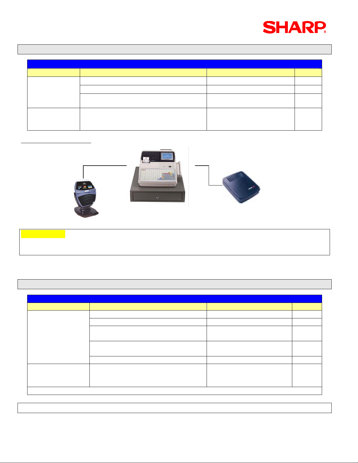
1. Standalone Configuration – Credit / Gift Card Only
Equipment List
Provider Dial Up - Standalone Configuration Model / Part No. Qty
Sharp
Local
Procurement
Configuration Diagram
POS Terminal UP700 1
Magnetic Card Reader UP-E13MR 1
Memory Option
*As required by File Allocation
Data Cap Data Tran 162SL
• Build File – Merchant Parameter Factory
Load
RS-232
RS-232
UP-S02MB UP-S04MB
1800.10
*Connection cables are included
RS-232
RS-232
1
Data Tran
Data Tran
UP-700 (+ ) UP-E13MR
UP-700 (+ ) UP-E13MRUP-700 (+ ) UP-E13MR
Data Tran
162SL
162SL
162SL
IMPORTANT:
The UP-700 incorporates Batch operations, Reporting functions, and Remote merchant parameter
setup through Dial Out and Dial In functions
Please consider the general rules listed below when using this feature:
• The telephone line used for credit card processing should not be shared with any other device
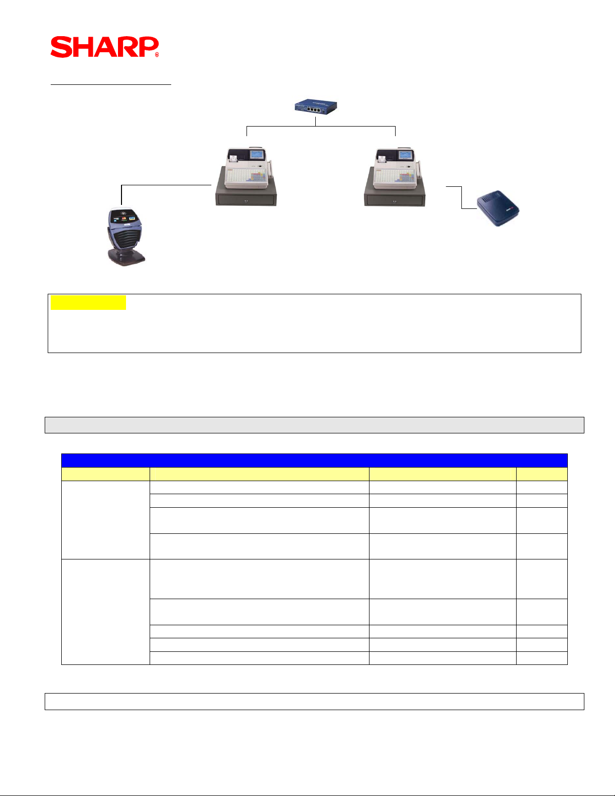
2. Inline Configuration – Credit / Gift Card Only
Equipment List
Provider Dial Up – IRC Configuration Model / Part No. Qty
Sharp
Local
Procurement
(x) = No. Terminals in system
POS Terminal UP-700 (x)
Magnetic Card Reader UP-E13MR (x)
8 MEG ROM VHi27801RAU3B
VHi27801RAV3B
Memory Option
*As required by File Allocation
Ethernet Hub ER-Hub1 or ER-Hub2 1
Data Cap Data Tran 162ML
• Build File – Merchant Parameter
Factory Load
UP-S02MB UP-S04MB
1800.20
*Connection cables are
included
2
1
Note: UP700 3B ROMs (VHi27801RAU3B/ VHi27801RAV3B) are available through NPC.
Page/ 2 Specifications subject to change without notice: Revision date February, 2006
Page 5
CREDIT CARD/GIFT CARD
Configuration Diagram
Ethernet
Ethernet
RS-232
RS-232
Data Tran
Data Tran
Data Tran
162ML
162ML
162ML
ViVOpay
ViVOpay
RS-232
RS-232
UP-700 (+)UP-E13MR
UP-700 (+)UP-E13MRUP-700 (+)UP-E13MR
UP-700 (+) UP-E13MR
UP-700 (+) UP-E13MR
IMPORTANT:
The UP-700 incorporates Batch operations, Reporting functions and Remote merchant parameter
setup through Dial Out and Dial In functions. The Data Tran 162 ML may be connected to either
the Master or Satellite
Please consider the general rules listed below when using this feature:
• The telephone line used for credit card processing should not be shared with any other device
• The Data Tran 162ML should be set for FTS MODE = Enabled for Inline operations
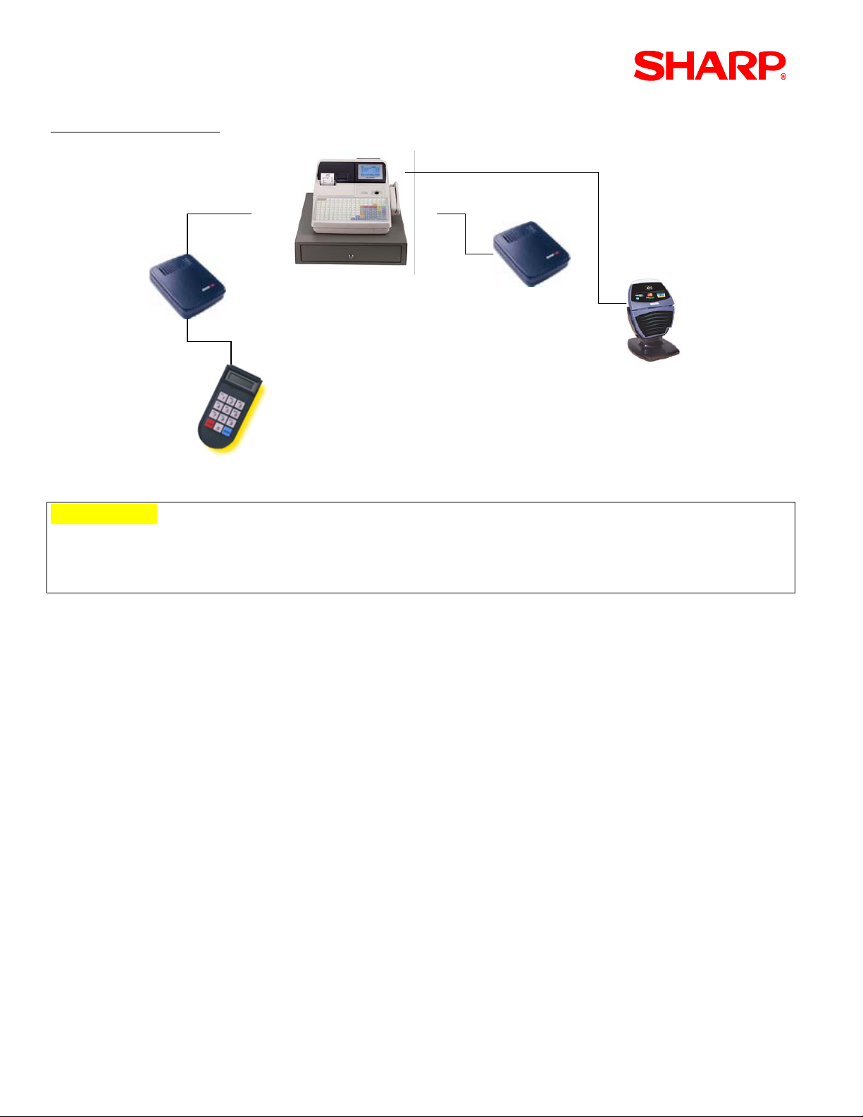
3. Standalone Configuration – Credit/Gift Card and Debit
Equipment List
Provider Dial Up - Standalone Configuration Model / Part No. Qty
Sharp
POS Terminal UP-700 1
Magnetic Card Reader UP-E13MR 1
8 MEG ROM VHi27801RAU3B
VHi27801RAV3B
Memory Option
UP-S02MB UP-S04MB
*As required
Local
Procurement Datacap
Data Cap Data Tran 162SL
• Build File – Merchant Parameter
Factory Load
Peripheral Device Controller includes
1800.10
*Connection cables are
included
1713.00 1
cable
Verifone PIN pad 1000 7020.01 1
Cable-A (ECR Æ PDC) 7866.01 1
Cable B (PDC Æ PIN pad 1000) 1332.10 1
Note
: UP700 3B ROMs (VHi27801RAU3B/ VHi27801RAV3B) are available through NPC.
2
1
Specifications subject to change without notice: Revision date February, 2006 Page/ 3
Page 6
UP-700 3B Version
Configuration Diagram
RS-232
RS-232RS-232
RS-232
Data Tran
Data Tran
PDC
PDC
Verifone PIN pad-1000
Verifone PIN pad-1000
RS-232
UP-700 (+ ) UP-E13MR
UP-700 (+ ) UP-E13MRUP-700 (+ ) UP-E13MR
RS-232
RS-232RS-232
Data Tran
Data Tran
162SL
162SL
ViVOpay
ViVOpay
IMPORTANT:
The UP-700 incorporates Batch operations, Reporting functions and Remote merchant parameter
setup through Dial Out and Dial In functions.
This configuration requires an ER-A5RS board for additional serial port capability.
Please consider the general rules listed below when using this feature:
• The telephone line used for credit card processing should not be shared with any other device
• The Verifone 1000 PIN pad must be setup by Data Cap for the type encryption method
• Assist the store owner with obtaining the necessary information from the bank
• Allow at least 1 week to obtain the merchant parameters – especially new accounts
• Always set up new merchant accounts - verify each card type to be used
• Schedule a test day with the processor to verify sales and batch operations
Page/ 4 Specifications subject to change without notice: Revision date February, 2006
Page 7
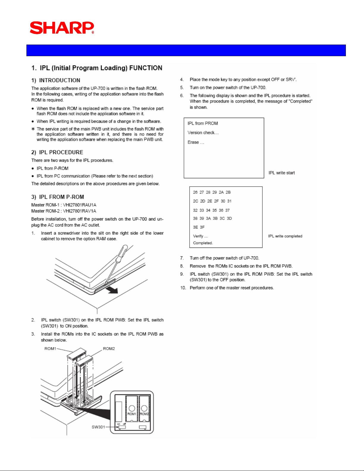
Section-1: IPL Procedures
CREDIT CARD/GIFT CARD
Specifications subject to change without notice: Revision date February, 2006 Page/ 5
Page 8
UP-700 3B Version
Section-2: Master Reset Procedures
Page/ 6 Specifications subject to change without notice: Revision date February, 2006
Page 9
Notes: Program data from a RAU1x/RAV1x are not compatible with 3B.
The POS Utility cannot be used when upgrading to 3B or downgrading from 3B to 1x.
CREDIT CARD/GIFT CARD
Specifications subject to change without notice: Revision date February, 2006 Page/ 7
Page 10

UP-700 3B Version
Section-3: Programming Principles
The UP-700 POS terminal incorporates the use of certain function keys to be used when making
changes in PGM-mode.
To simplify programming, please review the below list of function keys and usages listed below:
Function Description
K
K
The UP, DOWN, LEFT and RIGHT arrow keys are used to navigate within the specified menu
and/or preset entry field.
I
J
PAGE
UP
PAGE
DOWN
.
SBTL
ENTER
CA/AT
CL
CANCEL
Used to scroll the programming window back to the previous page
Used to scroll the programming window to the next page
Used to “toggle” between fixed selections within a preset entry field when it is applicable
The SUBTOTAL key is used to “List” available fixed selections within a present entry field when it
is applicable
Used to “set” each preset entry field
Used to “finalize” each preset entry
Used to clear the last setting you have programmed or clear an error state
Used to “cancel” programming and return to the previous screen
Page/ 8 Specifications subject to change without notice: Revision date February, 2006
Page 11
CREDIT CARD/GIFT CARD
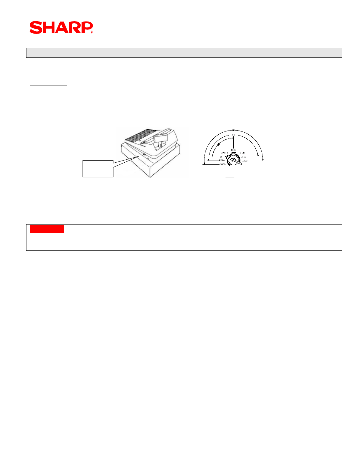
1. Entering the SRV-Mode
To enter SRV-mode programming, you must turn the SRV key counter clock wise to the 6 o’clock
position wait five seconds and turn the SRV key to the 7 o’clock position
Procedure:
① Turn the AC Power Switch “OFF”
② Set the mode switch to (SRV) position
③ Turn on the AC Power Switch “ON”
AC
Power
Sw i t c h
SRV
SRV
SRV
SRV ’
SRV ’
SRV ’
The SRV-mode Main Menu will appear:
CAUTION:
Never place the Service key to the SRV’ or SRV position while AC power is applied – severe
damage may result to the RAM and program contents
Specifications subject to change without notice: Revision date February, 2006 Page/ 9
Page 12
UP-700 3B Version
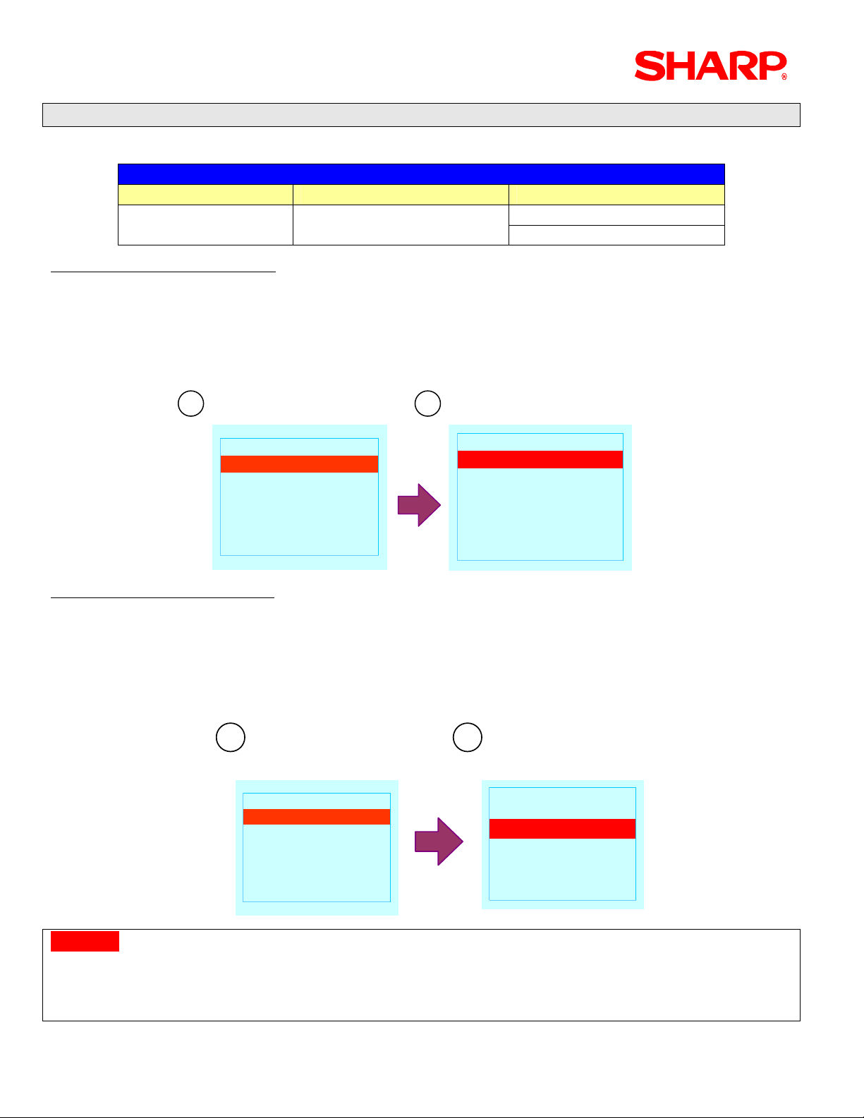
2. SRV-mode Program Readings:
List of SRV-mode Program Reports:
CAT#2 Related Jobs
Mode Main Menu Sub Menu
Procedure – System Preset:
① Enter the SRV-Mode as previously outlined
② Select [1 READING]
③ Select [1 SYSTEM PRESET]
④ This will automatically start to print.
1 2
SRV MODE
SRV MODE
READING
1
READING
1
SETTING
2
SETTING
2
IRC SETTING
3
IRC SETTING
3
DOWN LOAD
4
DOWN LOAD
4
DIAGNOSTIC
5
DIAGNOSTIC
5
READING
READING
SYSTEM PRESET
1
SYSTEM PRESET
1
DEVICE CONFIG
2
DEVICE CONFIG
2
FREE KEY
3
FREE KEY
3
FILE
4
FILE
4
SSP
5
SSP
5
1 SYSTEM PRESET SRV-Mode 1 READING
2 DEVICE CONFIG
Procedure – Device Assign:
① Enter the SRV-Mode as previously outlined
② Select [1 READING]
③ Select [2 DEVICE CONFIG]
④ This will automatically start to print.
1 2
READING
SRV MODE
SRV MODE
READING
1
READING
1
SETTING
2
SETTING
2
IRC SETTING
3
IRC SETTING
3
DOWN LOAD
4
DOWN LOAD
4
DIAGNOSTIC
5
DIAGNOSTIC
5
Caution:
When adding Credit Card devices, it is critical not to assign more than 1-type device to the same
channel no. Please verify that multiple type devices are not assigned to the same channel no.
READING
SYSTEM PRESET
1
SYSTEM PRESET
1
DEVICE CONFIG
2
DEVICE CONFIG
2
FREE KEY
3
FREE KEY
3
FILE
4
FILE
4
SSP
5
SSP
5
Example: CAT#2 and Printers “CANNOT” share the same Channel No. Assignment
Page/ 10 Specifications subject to change without notice: Revision date February, 2006
Page 13
CREDIT CARD/GIFT CARD
3. PGM-mode Program Readings:
The PGM mode readings for credit card devices are also associated to the other presets readings
(ex: Media Keys, etc.) that may be found within each section.
List of PGM2-mode Program Reports:
CAT#2 Related Jobs
Mode Main Menu Sub Menu
1 READING 11 MEDIA PGM2-Mode
11 CAT READING
Procedure – Media:
Enter the PGM2-Mode by turning the MA key counter clock wise to the PGM2 position
① Select [9 PGM2 MODE]
② Select [1 READING]
③ Select [11 MEDIA]
④ This will automatically start to print.
1 2
PGM2 MODE È
PGM2 MODE È
READING
1
READING
1
SETTING
2
SETTING
2
AUTO KEY
3
AUTO KEY
3
D-UPC LOAD
4
D-UPC LOAD
4
DATA CLEAR
5
DATA CLEAR
5
OPEN STORE6
OPEN STORE6
Print Example:
03/01/03
#0201 10:13
*PGM2*
MEDIA
CASH
CASH2
CHECK
CHECK2
CHECK3
CHECK4
CREDIT C
CREDIT-
:
:
000001
KP000 L18
00000000000000
CA1 00000000001
KP000 L18
00000000000000
CA2 00000000001
KP000 L18
00000000000000
CK1 00000000001
KP000 L18
00000000000000
CK2 00000000001
KP000 L18
00000000000000
CK3 00000000001
KP000 L18
00000000000000
CK4 00000000001
KP000 L18
00000000000000
CH1 20100000001
READING ÇÈ
READING ÇÈ
MIX & MATCH
6
MIX & MATCH
6
COMBO MEAL
7
COMBO MEAL
7
UPC OTHER
8
UPC OTHER
8
SCALE TABLE
9
SCALE TABLE
9
FUNCTION
10
FUNCTION
10
MEDIA11
MEDIA11
Specifications subject to change without notice: Revision date February, 2006 Page/ 11
Page 14

UP-700 3B Version
Procedure – CAT:
Enter the PGM2-Mode by turning the MA key counter clock wise to the PGM2 position
① Select [9 PGM2 MODE]
② Select [11 CAT READING]
③ This will automatically start to print.
PGM2 MODE ÇÈ
PGM2 MODE ÇÈ
KP SETTING
9
KP SETTING
9
ONLINE READING
10
ONLINE READING
10
ONLINE SETTING
11
ONLINE SETTING
11
CVM READING
12
CVM READING
12
CVM SETTING
13
CVM SETTING
13
CAT READING14
CAT READING14
Print Example:
03/01/03
#0202 10:13
*PGM2*
CAT READING
CAT PRESET#1
TIME OUT1
TIME OUT2
BAUD RATE
CAT PRESET#2
TIME OUT1
TIME OUT2
TIME OUT3
TEL NO.
TEL ID
TEL MODE
FTS MODE
AMOUNT%
CAT PRESET#3
TIME OUT1
TIME OUT2
BAUD RATE
PRODUCT CODE
PIN PAD
TIME OUT1
TIME OUT2
BAUD RATE
000001
9600 bps
TONE
DISABLE
0.00%
9600 bps
9600 bps
180
099
010
180
300
0
0
010
099
0
010
099
The Data Tran interface uses CAT PRESET#2
Page/ 12 Specifications subject to change without notice: Revision date February, 2006
Page 15

CREDIT CARD/GIFT CARD
Section-4: Cable Connection
Prior to programming, it is important to insure that the hardware connections necessary for each
device are accomplished. As a basic rule, the following steps may be used for each device:
1. Connecting the UP-700:
Procedure:
① Connect the specified RS232 cable to Channel #1
② Install a ferrite core (part no. RCORF6699BHZZ) within 50 cm of the connector on the
connection cable to reduce interference
1.
2.
2. Connecting the Datacap Data Tran 162 Modem – Dial Up Processing
The Datacap DataTran Modem is required for credit card authorization. For single terminal sites
either the DataTran 162 SL or 162 ML Modem may be used. Two or more terminal installations
require the 162 ML model.
1. Locate the Datacap cable (part no. SPCB-990805)
2. Insure that the AC power is disconnected from the UP-700
3. Connect the DB9 end to CH#1 of the UP-700.
Specifications subject to change without notice: Revision date February, 2006 Page/ 13
Page 16

UP-700 3B Version
4. Connect the 8-pin DIN connector to the DataTran 162 modem as indicated below.
5. Connect the RJ-11 (telephone) jack to the DataTran 162 modem as indicated below.
6. Connect the external power supply to the receptacle of the DataTran 162 modem.
7. Plug the external power supply to the AC power outlet.
Note:
1. When power is applied to the DataTran modem, there is an LED indicator in the front of the unit.
2. When AC Power is removed and re-applied, it is necessary to initialize the DataTran
Page/ 14 Specifications subject to change without notice: Revision date February, 2006
Page 17

V
CREDIT CARD/GIFT CARD
3. DataTran™/IPTran™/IPEnabler™ EFT Payments for Sharp UP-700 Registers
Procedure:
① Connect the specified RS232 cable to the 8-pin Din-type connector on the Data Tran 162 unit
② If using Debit Card operations connect the UP-700 to the 8-pin Din-type connector on the
Peripheral Device Controller
NOTE:
The illustrations above are based on the current Data Tran 162 SL and ML units
4. Connecting the ViVOpay Device
RS-232
UP-700
iVOpay Device
Note: The ViVOpay RS-232 cable comes with a DB-9 to RJ-45 connector.
Specifications subject to change without notice: Revision date February, 2006 Page/ 15
Page 18

UP-700 3B Version
5. Cabling Specifications
As a general rule, each peripheral’s manufacturer should provide their recommended
specifications for cabling to the peripheral device. Data Cap supplies the necessary cables
between their product and the UP-700.
Protocol:
Description Specification
Operation Mode Half Duplex
Line Configuration Direct connection
Data Rate 2400 bps
Transmission Technique Asynchronous
Connection Initiated by UP-600/700
1 Start bit
Checking
8 Data bits
No Parity
1 Stop bit
Code ASCII
Bit Sequence LSB first
Page/ 16 Specifications subject to change without notice: Revision date February, 2006
Page 19

CREDIT CARD/GIFT CARD
6. Standard D-Sub 9 Pin Connector:
CH1 utilizes a standard PC-type COM Port - EIA-574 RS-232 pin out on a DB-9 pin used for
Asynchronous Data
Specifications subject to change without notice: Revision date February, 2006 Page/ 17
Page 20

UP-700 3B Version
Section-5: EFT Related Programming
EFT (Electronic Funds Transfer) related programming includes Credit, Gift Card, Check and Debit
card authorization setup, which consist of service-mode and PGM-mode programming jobs, which
define the UP-700 system capabilities.
Recommendations:
Note: Prior to programming the UP-700, it MUST be upgraded using the physical ROM and it
is NOT recommended to upgrade it using the POSUTILITY.exe PC utility. (See the Service
Manual page 3-2 for procedures.)
Recommended Sequence for programming:
Please complete the SRV-mode and PGM-mode sections in the order outlined below:
① Always back up your existing program with the 02FD.EXE Utility prior to adding Credit
and/or Debit Card Authorization.
② Set the Device Configuration:
a. CAT#2
b. IC Card
c. PIN Pad
③ Set any applicable SRV Mode - System Presets
④ Place the necessary Function keys on the keyboard SRV Mode - Free Key Layout
⑤ Allocate any Memory Files SRV Mode – File Allocation
⑥ Perform a Program Reset (SRV Reset)
⑦ Set related presets in PGM2 mode
a. CAT Settings
b. Media Key presets
⑧ Initialize the Data Tran
⑨ Conduct a Test with the merchant's processor
a. Credit Card Sales
b. Gift Card Sales
c. Gift Card Redeem Sale
d. Debit Sale (if applicable)
Note: If the POS terminal needs to be downgraded to the 1xx version, a physical version of that
ROM is required. 1xx data are not compatible with the 3B version.
Page/ 18 Specifications subject to change without notice: Revision date February, 2006
Page 21

Related Programming Jobs: CAT#2 System
System Presets:
SRV Menu / Job# Description
CAT#2
IC Card SRV Mode - Device Config
PIN Pad
902-B Gift Reload Command to Data Tran
902-C Gift Card Command to Data Tran
SRV Mode – System Presets
SRV Mode – Free Key
SRV Mode – File Allocation File Group No. 73 Gift Card Buffer = 500
Note: These are minimal settings related to credit card function for the terminals. More
programming may be necessary as per end user specifications.
Caution:
Making changes to the Systems Presets that are related to Inline System control will require the
execution of the IRC SETTING job.
903-B Printing of Gift Card No. for Activate/Reload
906-B Gift Card No. for Activate /Reloads
980-B Hash/Gift Department Affect Hourly Sales
Function No. 059 CH TIP (Charge Tip)
Function No. 111 CHK (Check)
Function No. 112 CHK2 (Check2)
Function No. 113 CH K3 (Check3)
Function No. 114 CHK4 (Check4)
Function No. 115 CHK5 (Check5)
Function No. 116 CH1 (Charge1)
Function No. 117 CH2 (Charge2)
Function No. 118 CH3 (Charge3)
Function No. 119 CH4 (Charge4)
Function No. 120 CH5 (Charge5)
Function No. 121 CH6 (Charge6)
Function No. 122 CH7 (Charge7)
Function No. 123 CH8 (Charge8)
Function No. 124 CH9 (Charge9)
Function No. 172 ED TIP (Edit Tip)
Function No. 167 RCP. SW [Receipt
On/Off)]
CREDIT CARD/GIFT CARD
Please consider the general rules listed below when using this feature:
• An IRC SETTING is required after modification to memory file allocation
• A PROGRAM RESET is required upon modification
Specifications subject to change without notice: Revision date February, 2006 Page/ 19
Page 22

UP-700 3B Version
PGM2 Mode
PGM Job # Selection Description Options
2.Setting
15.CAT Setting
1. Cash
1. Article
1. Department
4. Media
2.CAT Preset#2
3.PIN Pad
4. IC Card Time Out 060
2. Charge
3. Service
4. Final
Time Out1 000 – 10
Time Out2 000 – 180
Time Out3 0000 – 3000
Tel No. 12 digits
Tel ID 8 digits
Tel Mode Tone/Pulse
FTS Mode Disable/Enable
Amount% 000.00% - 100.00%
Time Out1 000 – 255
Time Out2 000 – 255
Baud Rate 300/1200/2400/4800/9600/19200
CAT operation, CAT2 Action
Code, CAT2 Type, Card# Print,
Card# Format, Signature Line
Print, Card Holder Print, Expiration
Print, Number of Receipts,
IC Card
Page/ 20 Specifications subject to change without notice: Revision date February, 2006
Page 23

CREDIT CARD/GIFT CARD
1. Device Assign Settings
The SRV-mode programming of the UP-700 consists of Device Assignment, System Presets, Free
Key layout and File Allocation. The recommended settings are described below:
CAT#2
The CAT#2 device may be added to the UP-700 configuration when EFT functions are required.
The Data Tran modem is used for the CAT#2 device and may be setup as outlined below:
Procedure
Enter the SRV-Mode as outlined in Section -1
① Select [2 SETTING]
② Select [1 DEVICE CONFIG]
③ Select [15 CAT#2]
④ Enter the desired parameters followed by depressing the [ENTER] key
1 2 3 4
SRV MODE
SRV MODE
READING
1
READING
1
SETTING
2
SETTING
2
IRC SETTING
3
IRC SETTING
3
DOWN LOAD
4
DOWN LOAD
4
DIAGNOSTIC
5
DIAGNOSTIC
5
SETTING È
DEVICE CONFIG
1
DEVICE CONFIG
1
SYSTEM PRESET
2
SYSTEM PRESET
2
Z REPORT COUNTER
3
Z REPORT COUNTER
3
GT
4
GT
4
MODE SECRET#
5
MODE SECRET#
5
FREE KEY LAYOUT6
FREE KEY LAYOUT6
DEVICE CONFIG ÇÈ
DEVICE CONFIG ÇÈ
KP#6
10
KP#6
10
KP#7
11
KP#7
11
KP#8
12
KP#8
12
KP#9
13
KP#9
13
CAT#1
14
CAT#1
14
CAT#215
CAT#215
CAT#2
CAT#2
000TERMINAL#
000TERMINAL#
1CHANNEL#
1CHANNEL#
SETTING È
⑤ Depress the [CASH] key when all settings are completed
The menu will return to the Device Config Sub-Menu
⑥ Depress the [CANCEL] key to return to the SRV Mode Setting Sub-Menu
NOTE:
When the CAT#2 device is assigned to the desired Channel No., it is recommended that a
PROGRAM Reset be performed.
Assignment Method:
The CHANNEL NO. assignment is required at the machine where the CAT#2 device is physically
connected. For the Inline configuration – the TERMINAL and CHANNEL of the machine where the
Data Tran modem is physically located is required
Please consider the general rules listed below when using this feature:
• No other device can be assigned to a Channel where a the CAT#2 device is already
assigned (ex: SCALE)
Specifications subject to change without notice: Revision date February, 2006 Page/ 21
Page 24

UP-700 3B Version
PIN Pad
The PIN Pad device may be added to the UP-700 configuration when Debit Card w/ PIN entry
function is required. The Data Cap Peripheral Device Controller and Verifone PIN pad 1000 is
used for the PIN entry device and may be setup as outlined below:
Procedure
Enter the SRV-Mode as outlined in Section -1
① Select [2 SETTING]
② Select [1 DEVICE CONFIG]
③ Select [16 PIN PAD]
④ Enter the desired Channel# followed by depressing the [ENTER] key
1 2 3 4
SETTING È
SRV MODE
SRV MODE
READING
1
READING
1
SETTING
2
SETTING
2
IRC SETTING
3
IRC SETTING
3
DOWN LOAD
4
DOWN LOAD
4
DIAGNOSTIC
5
DIAGNOSTIC
5
SETTING È
DEVICE CONFIG
1
DEVICE CONFIG
1
SYSTEM PRESET
2
SYSTEM PRESET
2
Z REPORT COUNTER
3
Z REPORT COUNTER
3
GT
4
GT
4
MODE SECRET#
5
MODE SECRET#
5
FREE KEY LAYOUT6
FREE KEY LAYOUT6
DEVICE CONFIG ÇÈ
DEVICE CONFIG ÇÈ
KP#7
10
KP#7
10
KP#8
11
KP#8
11
KP#9
12
KP#9
12
CAT#1
13
CAT#1
13
CAT#2
14
CAT#2
14
PIN PAD15
PIN PAD15
PIN PAD
PIN PAD
2CHANNEL#
2CHANNEL#
⑤ Depress the [CASH] key when all settings are completed
The menu will return to the Device Config Sub-Menu
⑥ Depress the [CANCEL] key to return to the SRV Mode Setting Sub-Menu
NOTE:
When the PIN Pad device is assigned to the desired Channel No., it is recommended that a
PROGRAM Reset be performed.
Assignment Method:
The CHANNEL NO. assignment is required at every machine where the PIN Pad device
(Peripheral Device Controller) is physically connected.
Please consider the general rules listed below when using this feature:
• No other device can be assigned to a Channel where a the Peripheral Device Controller is
already assigned (ex: SCALE)
Page/ 22 Specifications subject to change without notice: Revision date February, 2006
Page 25

CREDIT CARD/GIFT CARD
IC Card
Procedure
Enter the SRV-Mode as outlined in Section -1.
① Select [2 SETTING]
② Select [1 DEVICE CONFIG]
③ Select [24 IC CARD]
④ Enter the desired Channel# followed by depressing the [ENTER] key.
1 2 3 4
1 2 3 4
SETTING
SETTING
SETTING
SETTING
SETTING
SETTING
SETTING
SRV MODE
SRV MODE
SRV MODE
SRV MODE
SRV MODE
SRV MODE
SRV MODE
SRV MODE
READING
1
READING
1
READING
1
READING
1
READING
1
READING
1
READING
1
READING
1
SETTING
2
SETTING
2
SETTING
2
SETTING
2
SETTING
2
SETTING
2
SETTING
2
SETTING
2
IRC SETTING
3
IRC SETTING
3
IRC SETTING
3
IRC SETTING
3
IRC SETTING
3
IRC SETTING
3
IRC SETTING
3
IRC SETTING
3
DOWN LOAD
4
DOWN LOAD
4
DOWN LOAD
4
DOWN LOAD
4
DOWN LOAD
4
DOWN LOAD
4
DOWN LOAD
4
DOWN LOAD
4
DIAGNOSTIC
5
DIAGNOSTIC
5
DIAGNOSTIC
5
DIAGNOSTIC
5
DIAGNOSTIC
5
DIAGNOSTIC
5
DIAGNOSTIC
5
DIAGNOSTIC
5
SETTING
DEVICE CONFIG
1
DEVICE CONFIG
1
DEVICE CONFIG
1
DEVICE CONFIG
1
DEVICE CONFIG
1
DEVICE CONFIG
1
DEVICE CONFIG
1
DEVICE CONFIG
1
SYSTEM PRESET
2
SYSTEM PRESET
2
SYSTEM PRESET
2
SYSTEM PRESET
2
SYSTEM PRESET
2
SYSTEM PRESET
2
SYSTEM PRESET
2
SYSTEM PRESET
2
Z REPORT COUNTER
3
Z REPORT COUNTER
3
Z REPORT COUNTER
3
Z REPORT COUNTER
3
Z REPORT COUNTER
3
Z REPORT COUNTER
3
Z REPORT COUNTER
3
Z REPORT COUNTER
3
GT
4
GT
4
GT
4
GT
4
GT
4
GT
4
GT
4
GT
4
MODE SECRET#
5
MODE SECRET#
5
MODE SECRET#
5
MODE SECRET#
5
MODE SECRET#
5
MODE SECRET#
5
MODE SECRET#
5
MODE SECRET#
5
FREE KEY LAYOUT6
FREE KEY LAYOUT6
FREE KEY LAYOUT6
FREE KEY LAYOUT6
FREE KEY LAYOUT6
FREE KEY LAYOUT6
FREE KEY LAYOUT6
FREE KEY LAYOUT6
È
È
È
È
È
È
È
È
DEVICE CONFIG
DEVICE CONFIG
DEVICE CONFIG
DEVICE CONFIG
DEVICE CONFIG
DEVICE CONFIG
KP#7
10
COIN DISP.
19
KP#7
10
COIN DISP.
19
KP#7
10
COIN DISP.
19
KP#8
11
ONLINE
20
KP#8
11
ONLINE
20
KP#8
11
ONLINE
20
21
21
21
CUM DATA I/F
CUM DATA I/F
CUM DATA I/F
22
22
22
PREPAID CARD
PREPAID CARD
PREPAID CARD
ONL ACCT BAL
23
ONL ACCT BAL
23
ONL ACCT BAL
23
PIN PAD15
IC CARD24
PIN PAD15
IC CARD24
PIN PAD15
IC CARD24
ÇÈ
ÇÈ
ÇÈ
ÇÈ
ÇÈ
ÇÈ
IC CARD
IC CARD
2CHANNEL#
1CHANNEL#
2CHANNEL#
1CHANNEL#
2. System Preset Settings
There are System Preset jobs that should be preset with recommended values based on the
requirements of UP-700 system configuration and are described below:
Procedure
Enter the SRV-Mode as outlined in Section -1
① Select [2 SETTING]
② Select [2 SYSTEM PRESET]
③ Enter the desired parameters:
° SRV#902 = 0310 when ViVOpay is Stand Alone (1310 when Inline) is recommended
= xx2x: when the Network is Host-based
= xxxx: when the Network is Terminal-based (Batch operations)
= xx1x: Gift Card Command to DataTran
=x4xx: Gift Reload Command to DataTran
=x2xx: Ref# and AP Code entry for void of Gift Sales Non-Compulsory
° SRV#903 = x1xx: Printing of Gift Card Number for Activations/Reloads
° SRV#906 = x2xx: Gift Card Number for Activations/Reloads
° SRV#916 = x4xx, SRV#918 = xxx1 and SRV#921 = xxx4
° SRV#980 = x1xx: Hash/Gift Department affects Hourly Sales
Note: SRV#906-C must disable fast food to allow Open Price PLU.
Specifications subject to change without notice: Revision date February, 2006 Page/ 23
Page 26

UP-700 3B Version
)
1 2 3
1 2 3
SETTING
SETTING
SETTING
SRV MODE
SRV MODE
SRV MODE
SRV MODE
READING
1
READING
1
READING
1
READING
1
SETTING
2
SETTING
2
SETTING
2
SETTING
2
IRC SETTING
3
IRC SETTING
3
IRC SETTING
3
IRC SETTING
3
DOWN LOAD
4
DOWN LOAD
4
DOWN LOAD
4
DOWN LOAD
4
DIAGNOSTIC
5
DIAGNOSTIC
5
DIAGNOSTIC
5
DIAGNOSTIC
5
SETTING
DEVICE CONFIG
1
DEVICE CONFIG
1
DEVICE CONFIG
1
DEVICE CONFIG
1
SYSTEM PRESET
2
SYSTEM PRESET
2
SYSTEM PRESET
2
SYSTEM PRESET
2
Z REPORT COUNTER
3
Z REPORT COUNTER
3
Z REPORT COUNTER
3
Z REPORT COUNTER
3
GT
4
GT
4
GT
4
GT
4
MODE SECRET#
5
MODE SECRET#
5
MODE SECRET#
5
MODE SECRET#
5
FREE KEY LAYOUT6
FREE KEY LAYOUT6
FREE KEY LAYOUT6
FREE KEY LAYOUT6
È
È
È
È
SYSTEM PRESET
SYSTEM PRESET
SYSTEM PRESET
SYSTEM PRESET
1400SRV#901
0002
1400SRV#901
0002
0310SRV#902
0310SRV#902
2233SRV#903
2233SRV#903
8100
8100
5100SRV#904
0000
5100SRV#904
0000
0005SRV#905
0005SRV#905
0221SRV#906
0221SRV#906
4
4
SYSTEM PRESET
SYSTEM PRESET
SYSTEM PRESET
SYSTEM PRESET
SYSTEM PRESET
SYSTEM PRESET
SRV#921
SRV#921
SRV#921
1400SRV#916
1400SRV#916
1400SRV#916
1400SRV#916
1400SRV#916
1400SRV#916
0000SRV#917
0000SRV#917
0000SRV#917
0000SRV#917
0000SRV#917
0000SRV#917
2233SRV#918
2233SRV#918
2233SRV#918
2233SRV#918
2233SRV#918
2233SRV#918
5100SRV#919
5100SRV#919
5100SRV#919
5100SRV#919
5100SRV#919
5100SRV#919
2040SRV#920
2040SRV#920
2040SRV#920
2040SRV#920
2040SRV#920
2040SRV#920
0004SRV#921
0004SRV#921
0004SRV#921
SRV#902-C (based on network type
SRV#903-B = “1”
SRV#906-B = ”2”
SRV#916-B = “4”
SRV#918-D = “1”
SRV#921-D = “4”
SYSTEM PRESET
SYSTEM PRESET
SYSTEM PRESET
SYSTEM PRESET
SYSTEM PRESET
SYSTEM PRESET
5
5
1400SRV#926
0000
1400SRV#926
0000
1400SRV#926
0000
0000SRV#927
0000SRV#927
0000SRV#927
1060SRV#928
1060SRV#928
1060SRV#928
5100SRV#929
0000
5100SRV#929
0000
5100SRV#929
0000
0100SRV#980
0100SRV#980
0100SRV#980
0000SRV#981
0000SRV#981
0000SRV#981
SRV#980-B = “1”
④ Depress the [CASH] key when all settings are completed
⑤ Depress the [CANCEL] key to return to the SRV Mode Setting Sub-Menu
NOTE:
SRV#918 and #921 are related to the Server Tip Paid function, which impacts the usage of the Edit
Tip entry used for Credit Card Authorization.
Page/ 24 Specifications subject to change without notice: Revision date February, 2006
Page 27

CREDIT CARD/GIFT CARD
3. Free Key Layout Settings
The Function keys required and the description for recommended usage are shown below:
Recommended Function Keys
Function Description
CA2
CHK1-4
CH1-8
PAY
MENT
CH TIP
ED
TIP
RCPT
The CA2 (Cash2) media key is preset for Debit settlement
The Check1 – 4 media keys are preset for Checks and/or Check-Card settlements (w/o MICR)
The Charge1 -8 media keys are preset for Credit Card and/or Check Card settlements
Used to organize all payments within a single keyboard
The Charge Tip function is used to enter Tips included in Credit Card sales prior to finalization
The Edit Tip function key is used in conjunction with the Closed Check file and may only be used
for modifying a Tip entry for Guest Check transaction
nd
The Receipt Copy key is used to issue a receipt or generate 2
transaction.
or subsequent copies of the sales
Specifications subject to change without notice: Revision date February, 2006 Page/ 25
Page 28

UP-700 3B Version
T
T
T
T
R
T
T
T
T
T
R
T
T
T
T
T
T
T
T
T
R
T
T
T
T
T
R
T
T
T
T
T
Example Free Key Layout Programming
Procedure
Enter the SRV-Mode as outlined in Section -1
① Select [2 SETTING]
② Select [6 FREE KEY]
③ Using the UP and DOWN arrow keys, scroll to the desired Function key and depress the
desired location on the keyboard
1 2 3
1 2 3
SETTING
SETTING
SETTING
SRV MODE
SRV MODE
SRV MODE
SRV MODE
READING
1
READING
1
READING
1
READING
1
SETTING
2
SETTING
2
SETTING
2
SETTING
2
IRC SETTING
3
IRC SETTING
3
IRC SETTING
3
IRC SETTING
3
DOWN LOAD
4
DOWN LOAD
4
DOWN LOAD
4
DOWN LOAD
4
DIAGNOSTIC
5
DIAGNOSTIC
5
DIAGNOSTIC
5
DIAGNOSTIC
5
UP - T80BP UTILITY
UP - T80BP UTILITY
UP - T80BP UTILITY
UP - T80BP UTILITY
6
6
6
6
SETTING
DEVICE ASSIGN
1
DEVICE ASSIGN
1
DEVICE ASSIGN
1
DEVICE ASSIGN
1
SYSTEM PRESE
2
SYSTEM PRESE
2
SYSTEM PRESE
2
SYSTEM PRESE
2
Z REPORT COUNTE
3
Z REPORT COUNTE
3
Z REPORT COUNTE
3
Z REPORT COUNTE
3
G
G
G
G
4
4
4
4
MODE SECRET#
MODE SECRET#
5
5
5
5
MODE SECRET#
MODE SECRET#
FREE KEY LAYOU
6
FREE KEY LAYOU
6
FREE KEY LAYOU
6
FREE KEY LAYOU
6
DISPLAY LAYOU
7
DISPLAY LAYOU
7
DISPLAY LAYOU
7
DISPLAY LAYOU
7
INIT. KEY LAYOU
8
INIT. KEY LAYOU
8
INIT. KEY LAYOU
8
INIT. KEY LAYOU
8
FILE9
FILE9
FILE9
FILE9
SUPERVISOR ON/OFF10
SUPERVISOR ON/OFF10
SUPERVISOR ON/OFF10
SUPERVISOR ON/OFF10
11
11
11
11
MEMORY INTIAL
MEMORY INTIAL
MEMORY INTIAL
MEMORY INTIAL
È
È
FREE KEY
FREE KEY
11
024
11
024
025
025
026
026
027
027
028
028
029
029
CA/A
P UP
CA/A
P UP
P DOWN
P DOWN
BKSPC
BKSPC
DEL
DEL
MDS S
MDS S
RY S
RY S
Ç✟È
ÇÈ
✟
Scroll to the
Scroll to the
desired
desired
Function Key
Function Key
and depress the
and depress the
location
location
④ Depress the [ENTER] key located on the Receipt-Window when all settings are completed
⑤ Depress the [CANCEL] key to return to the SRV Mode Setting Sub-Menu
NOTE:
When placing Function keys on the keyboard please refer to the Section 2: Free Key Layout for
further information
Page/ 26 Specifications subject to change without notice: Revision date February, 2006
Page 29

CREDIT CARD/GIFT CARD
4. File Allocation
Allocation of memory files is necessary when Gift Card function is required.
Assignment Method:
The below example assumes the following scenario:
• The system is a One-Machine configuration
Procedure
Enter the SRV-Mode as outlined in Section -1
① Select [2 SETTING]
② Select [8 FILE]
③ Select [73 GIFT CARD BUFFER]
④ Enter the desired parameters:
° Records: 500
⑤ Depress the [ENTER] key to finalize the settings
Example – GIFT CARD
1 2 3 4
1 2 3 4
SETTING
SETTING
SETTING
SETTING
SETTING
SETTING
SETTING
SRV MODE
SRV MODE
SRV MODE
SRV MODE
SRV MODE
SRV MODE
SRV MODE
SRV MODE
READING
1
READING
1
READING
1
READING
1
READING
1
READING
1
READING
1
READING
1
SETTING
2
SETTING
2
SETTING
2
SETTING
2
SETTING
2
SETTING
2
SETTING
2
SETTING
2
IRC SETTING
3
IRC SETTING
3
IRC SETTING
3
IRC SETTING
3
IRC SETTING
3
IRC SETTING
3
IRC SETTING
3
IRC SETTING
3
DOWN LOAD
4
DOWN LOAD
4
DOWN LOAD
4
DOWN LOAD
4
DOWN LOAD
4
DOWN LOAD
4
DOWN LOAD
4
DOWN LOAD
4
DIAGNOSTIC
5
DIAGNOSTIC
5
DIAGNOSTIC
5
DIAGNOSTIC
5
DIAGNOSTIC
5
DIAGNOSTIC
5
DIAGNOSTIC
5
DIAGNOSTIC
5
SETTING
Z COUNTER
3
Z COUNTER
3
Z COUNTER
3
Z COUNTER
3
Z COUNTER
3
Z COUNTER
3
Z COUNTER
3
Z COUNTER
3
GT
4
GT
4
GT
4
GT
4
GT
4
GT
4
GT
4
GT
4
MODE SECRET#
5
MODE SECRET#
5
MODE SECRET#
5
MODE SECRET#
5
MODE SECRET#
5
MODE SECRET#
5
MODE SECRET#
5
MODE SECRET#
5
FREE KEY LAYOUT
6
FREE KEY LAYOUT
6
FREE KEY LAYOUT
6
FREE KEY LAYOUT
6
FREE KEY LAYOUT
6
FREE KEY LAYOUT
6
FREE KEY LAYOUT
6
FREE KEY LAYOUT
6
KEY INITIAL
7
KEY INITIAL
7
KEY INITIAL
7
KEY INITIAL
7
KEY INITIAL
7
KEY INITIAL
7
KEY INITIAL
7
KEY INITIAL
7
FILE8
FILE8
FILE8
FILE8
FILE8
FILE8
FILE8
FILE8
ÇÈ
ÇÈ
ÇÈ
ÇÈ
ÇÈ
ÇÈ
ÇÈ
ÇÈ
FILE
FILE
FILE
FILE
SIGN OFF SERV.33
TERM DYM.UPC68
SIGN OFF SERV.33
TERM DYM.UPC68
PICK UP D.X2
PICK UP D.X2
34
69
34
69
DAILY NET
35
PLU ENH.SALES
70
DAILY NET
35
PLU ENH.SALES
70
REG BUFFER
36
RCV.CH.POST
71
REG BUFFER
36
RCV.CH.POST
71
KP BUFFER
37
ACCT BAL OFF
72
KP BUFFER
37
ACCT BAL OFF
72
GLU PBLU (ALL)
38
GIFT CARD BUF.
73
GLU PBLU (ALL)
38
GIFT CARD BUF.
73
Ç
Ç
GIFT CARD BUF.
GIFT CARD BUF.
GIFT CARD BUF.
0000RECORD
00500
0000RECORD
005000000RECORD
00500
Specifications subject to change without notice: Revision date February, 2006 Page/ 27
Page 30

UP-700 3B Version
5. PGM2 mode programming:
The PGM2 mode-programming settings outlined in this section are recommended settings for a
typical implementation of the UP-700 CAT#2 function for credit card, gift card, debit card and/or
personal checks.
CAT#2 Settings:
Procedure:
Place the mode key to the PGM2 position
① Select [15 CAT SETTING]
② Select [2 CAT PRESET#2]
③ Set the following parameters time-out values as shown below followed by depressing the [ENTER] key
o TIMEOUT1 = 010
o TIMEOUT2 = 180
o TIMEOUT3 = 3000
④ Set the TEL NO. as instructed for DIAL OUT purposes – using the [TEXT] keyboard
o Example: TEL NO. = 1,2159973963
⑤ Set the TEL ID to the designated number provided by Data Cap for that merchant file or DIAL OUT purposes
⑥ Set TEL MODE to the desired setting followed by depressing the [ENTER] key
⑦ Set FTS MODE = ENABLE for Inline systems or DISABLE for Stand-alone machines
⑧ Set the AMOUNT% only when CH. Tips are used
⑨ Depress the [ENTER] key to finalize the settings
⑩ Depress [CANCEL] when at the CAT SETTING sub-menu to exit to the PGM2 Main-Menu
1 2 3 4
PRESET
PGM2 MODE ÇÈ
PGM2 MODE ÇÈ
ONLINE READING
10
ONLINE READING
10
ONLINE SETTING
11
ONLINE SETTING
11
CVM READING
12
CVM READING
12
CVM SETTING
13
CVM SETTING
13
CAT READING
14
CAT READING
14
CAT SETTING15
CAT SETTING15
CAT SETTING
CAT SETTING
CAT PRESET#1
1
CAT PRESET#1
1
CAT PRESET#2
2
CAT PRESET#2
2
PIN PAD
PIN PAD
3
3
CAT PRESET #2
CAT PRESET #2
INITIALIZE
1
INITIALIZE
1
DIAL OUT
2
DIAL OUT
2
DIAL IN
3
DIAL IN
3
PRESET
4
PRESET
4
PRESET
000000000000TEL NO.
000000000000TEL NO.
1400TIME OUT3
1400TIME OUT3
00000000TEL ID
00000000TEL ID
TONETEL MODE
TONETEL MODE
DISABLEFTS MODE
DISABLEFTS MODE
0.00%AMOUNT%
0.00%AMOUNT%
NOTE:
The AMOUNT% is used as a calculation basis for Data Tran’s Authorization Amount parameter. It
is recommended to set this parameter = 15.00% - 50.00% when using the CH Tip function
Assignment Method:
When using Nova or any other Host-based service, the Amount% should be preset to %0. 00
Page/ 28 Specifications subject to change without notice: Revision date February, 2006
Page 31

CREDIT CARD/GIFT CARD
PIN Pad Settings:
Procedure:
Place the mode key to the PGM2 position
① Select [15 CAT SETTING]
② Select [3 PIN PAD]
③ Set the following parameters time-out values as shown below followed by depressing the [ENTER] key
o TIMEOUT1 = 010
o TIMEOUT2 = 099
o BAUD RATE = 9600 bps
④ Depress the [ENTER] key to finalize the settings
⑤ Depress [CANCEL] when at the CAT SETTING sub-menu to exit to the PGM2 Main-Menu
1 2 3
PIN PAD
PGM2 MODE ÇÈ
PGM2 MODE ÇÈ
ONLINE READING
10
ONLINE READING
10
ONLINE SETTING
11
ONLINE SETTING
11
CVM READING
12
CVM READING
12
CVM SETTING
13
CVM SETTING
13
CAT READING
14
CAT READING
14
CAT SETTING15
CAT SETTING15
CAT SETTING
CAT SETTING
CAT PRESET#1
1
CAT PRESET#1
1
CAT PRESET#2
2
CAT PRESET#2
2
PIN PAD
3
PIN PAD
3
PIN PAD
010TIME OUT1
010TIME OUT1
099TIME OUT2
099TIME OUT2
9600 bpsBAUD RATE
9600 bpsBAUD RATE
NOTE:
The PIN Pad settings are preset to the recommended settings from MRS Defaults.
IC Card Settings:
1 2 3
1 2 3
PGM2
PGM2
DEVICE CONFIG
1
DEVICE CONFIG
1
CAT READING
14
CAT READING
14
SYSTEM PRESET
2
SYSTEM PRESET
2
CAT SETTING
15
CAT SETTING
15
ACCT READING
16
ACCT READING
16
ACCT SETTING
17
ACCT SETTING
17
MWS READING
18
MWS READING
18
MWS SETTING19
MWS SETTING19
Ç
Ç
CAT SETTINGS
CAT SETTINGS
KP#7
10
CAT PRESET#1
1
KP#7
10
CAT PRESET#1
1
KP#8
11
CAT PRESET#2
2
KP#8
11
CAT PRESET#2
2
PIN PAD
3
PIN PAD
3
IC CARD
4
IC CARD
4
IC CARD
IC CARD
060
060
2TIME OUT1
2TIME OUT1
Specifications subject to change without notice: Revision date February, 2006 Page/ 29
Page 32

UP-700 3B Version
Department and PLU Programming Settings:
Create two new departments. For the first department, set its Department Type to GIFT. Set the
other department’s Department Type to GIFT RELOAD.
① Create two new PLUs.
a. For the first new PLU, change its text to Gift Card Activate (or whatever you prefer)
and link it to the newly created GIFT department (step 1). For the PLU’s pricing, set
its Entry Type to Open.
b. For the 2
nd
PLU, change its text to Gift Card Reload (or whatever you prefer) and link
it to the newly created GIFT RELOAD department (step 1). For the PLU’s pricing, set
its Entry Type to Open.
6. Media Key programming:
The media key initiates communications to the Data Tran unit based on the presets entered during setup. The
below procedures are separated by the type media key:
Credit Card Finalization Keys with ViVO pay:
There are two methods in which to set the system for credit card finalization.
Method-1: for simplified operations:
It is possible to provide a single Credit Card key and rely on the Data Tran terminal to track the individual credit
card's totalizers.
Method-2: for detailed operations:
It is possible to provide a media key for each type of credit card at the POS terminal and cross check the
machine's totalizers against the Data Tran.
Procedure:
Enter the PGM2-Mode by turning the MA key counter clock wise to the PGM2 position
① Select [2 SETTING]
② Select [5 MEDIA]
③ Select [3 CHARGE]
④ Select the desired Charge media key(s) to be used for Credit Cards (CHARGE1 – CHARGE8)
⑤ Enter the desired parameters:
° CAT Operation: CAT2 Compulsory
° CAT2 Action Code: Dial
° CAT2 Type: Credit
° Card# Print: Yes or No
° Card# Format: Full or Partial
° Sign. Line Print: Yes or No
° Card Holder Print: Yes or No
° Expiration Date Print: Yes or No
° Number of Receipts: 0 – 9 (usually 2)
° IC Card Yes
Page/ 30 Specifications subject to change without notice: Revision date February, 2006
Page 33

CREDIT CARD/GIFT CARD
⑥ Depress [CA/AT] when all settings are completed to exit to the PGM2 Charge Sub-Menu
⑦ Depress [CANCEL] to exit the Charge Sub-Menu and return to the Media preset menu
NOTE:
Repeat steps 4 thru 7 for each subsequent charge card to be programmed as a credit card
finalization key.
1 2 3 4
CHARGE È
PGM2 MODE È
PGM2 MODE È
READING
1
READING
1
SETTING
2
SETTING
2
AUTO KEY
3
AUTO KEY
3
D-UPC LOAD
4
D-UPC LOAD
4
DATA CLEAR
5
DATA CLEAR
5
OPEN STORE6
OPEN STORE6
SETTING È
ARTICLE
1
ARTICLE
1
DIRECT KEY
2
DIRECT KEY
2
PLU MENU KEY
3
PLU MENU KEY
3
FUNCTION
4
FUNCTION
4
MEDIA
5
MEDIA
5
TEXT6
TEXT6
MEDIA È
MEDIA È
ARTICLE
1
ARTICLE
1
CHECK
2
CHECK
2
CHARGE
3
CHARGE
3
FS TEND
4
FS TEND
4
CONVERSION
5
CONVERSION
5
EAT-IN6
EAT-IN6
SETTING È
5 6 7
CHARGE1 ÇÈ
CHARGE1 ÇÈ
NOT COMPUL.CAT
NOT COMPUL.CAT
NOT TRANSMITCAT1
NOT TRANSMITCAT1
POST-AUTHCAT2
POST-AUTHCAT2
CREDITCAT2
CREDITCAT2
NOCHIT RECEIPT
NOCHIT RECEIPT
00DATA ENT. JOB#
00DATA ENT. JOB#
CHARGE1 ÇÈ
CHARGE1 ÇÈ
YESCARD# PRT.
YESCARD# PRT.
PARTIALCARD# FROMAT
PARTIALCARD# FROMAT
YESSIGN. LINE PRT.
YESSIGN. LINE PRT.
YESCARD HOLD. PRT
YESCARD HOLD. PRT
YESEXPIRATION PRT
YESEXPIRATION PRT
2NUMBER OF RCPT
2NUMBER OF RCPT
CHARGE1 ÇÈ
CHARGE1 ÇÈ
CHARGE È
CHARGE1
1
CHARGE1
1
CHARGE2
2
CHARGE2
2
CHARGE3
3
CHARGE3
3
CHARGE4
4
CHARGE4
4
CAHRGE5
5
CAHRGE5
5
CHARGE66
CHARGE66
NOTAX1 DELETE
NOTAX1 DELETE
NOTAX2 DELETE
NOTAX2 DELETE
NOTAX3 DELETE
NOTAX3 DELETE
NOTAX4 DELETE
NOTAX4 DELETE
YESDRAWER OPENING
YESDRAWER OPENING
INHIBITAMOUNT
INHIBITAMOUNT
Assignment Method:
For terminal-based host systems (batch operations required), it is recommended to select a single
CHARGE media key when settling credit cards to simplify operations for the operator. The
individual Credit Card totals are provided upon the CAT#2 reports.
Please consider the general rules listed below when using this feature:
• When the Tip Line is not desired, then preset Sign. Line Print = No
• Preset the Footer Print related programming in SRV Job#911-C = “+1”
• Enable Footer Print = Enable for the Media key preset
• Partial tenders are required, the Charge media key must be preset as ‘Amount Tender = Compulsory”
Gift Card Finalization Keys:
The Gift Card is processed in a similar fashion to credit cards when using the Data Tran unit. Additionally, some
requirements that exist for Credit cards (ex: signature, adding tips, etc.) are also a requirement when this type of
card finalizes the sales transaction.
Assignment Method:
To keep the system-balancing simple, we recommend that a single Charge media key be preset
for all Gift Cards. Settings for Gift Cards are identical to Credit Cards with the exception of the Text
parameters.
Specifications subject to change without notice: Revision date February, 2006 Page/ 31
Page 34

UP-700 3B Version
Gift Card Finalization Keys: (w/ Manual Data Input):
The UP-700 can also support end user requirements that include processing the traditional written
Check as a form of sales finalization. The method that is used with Check finalization is supported
with data entry versus a MICR reader.
Datacap Notes about Mercury Payment Loyalty Program
Current certified dial gift card interfaces (UP-700 with DataTran SL/ML):
• FDMS Gift card (new account cert. Required)
• GCS Gift card (new POS/account cert. Required)
• Mercury Pay gift card. Please note: The Mercury Payment Loyalty Program is not supported.
• Mellennia gift card.
• OPT/OptiCard
• Paymentech gift card
• Sterling Pay gift card
• STS gift card (in certification)
• SVS Gift card (new POS/account cert required)
• ValueLink gift card (new account cert required)
• Valutec gift card
• Others – contact Datacap
Current certified IP/dial gift card interfaces (UP-700 with DataTran SL/ML and IPTran/Enhanced):
• FDMS Gift card (new account cert. Required)
• GCS Gift card (new POS/account cert. Required)
• Mercury Pay gift card. NOTE: The Mercury Payment Loyalty Program is not supported.
• Paymentech gift card
• Sterling Pay gift card
• SVS Gift card (new POS/account cert required)
• ValueLink gift card (new account cert required)
• Others-contact Datacap
Current certified dial gift card interfaces(UP-700 with DataTran SL/ML and IPTran/Basic):
• FDMS Gift card (new account cert. Required)
• GCS Gift card (new POS/account cert. Required)
• Mercury Pay gift card. Please note: The Mercury Payment Loyalty Program is not supported.
• Mellennia gift card.
• OPT/OptiCard
• Paymentech gift card
Page/ 32 Specifications subject to change without notice: Revision date February, 2006
Page 35

• Sterling Pay gift card
• STS gift card (in certification)
• SVS Gift card (new POS/account cert required)
• ValueLink gift card (new account cert required)
• Valutec gift card
• Others – contact Datacap
Certified GIFTePay IP gift card interfaces:
• Mercury Pay gift card. Please note: The Mercury Payment Loyalty Program is not supported.
• Sterling Pay gift card
• Concord gift card (in certification)
• Givex Gift card (new POS cert required)
• Nova gift card
• Others – contact Datacap
Procedure:
CREDIT CARD/GIFT CARD
Enter the PGM2-Mode by turning the MA key counter clock wise to the PGM2 position
① Select [2 SETTING]
② Select [5 MEDIA]
③ Select [2 CHECK]
④ Select the desired Check media key(s) to be used for Check payments (CHECK1 – CHECK4)
⑤ Enter the desired parameters:
° CAT Operation: CAT2 Compulsory
° CAT2 Action Code: Dial
° CAT2 Type: GIFT
° Card# Print: No
° Card# Format: Full
° Sign. Line Print: No
° Card Holder Print: No
° Expiration Date Print: No
° Number of Receipts: 0 – 9 (usually 2)
° IC Card Yes
⑥ Depress [CA/AT] when all settings are completed to exit to the PGM2 Check Sub-Menu
⑦ Depress [CANCEL] to exit the Charge Sub-Menu and return to the Media preset menu
NOTE:
Repeat steps 4 thru 7 for each subsequent check settlement key to be programmed as a check
finalization key
Specifications subject to change without notice: Revision date February, 2006 Page/ 33
Page 36

UP-700 3B Version
1 2 3 4
CHECK È
PGM2 MODE È
PGM2 MODE È
READING
1
READING
1
SETTING
2
SETTING
2
AUTO KEY
3
AUTO KEY
3
D-UPC LOAD
4
D-UPC LOAD
4
DATA CLEAR
5
DATA CLEAR
5
OPEN STORE6
OPEN STORE6
SETTING È
SETTING È
ARTICLE
1
ARTICLE
1
DIRECT KEY
2
DIRECT KEY
2
PLU MENU KEY
3
PLU MENU KEY
3
FUNCTION
4
FUNCTION
4
MEDIA
5
MEDIA
5
TEXT6
TEXT6
MEDIA È
MEDIA È
CASH
1
CASH
1
CHECK
2
CHECK
2
CHARGE
3
CHARGE
3
FS TEND
4
FS TEND
4
CONVERSION
5
CONVERSION
5
EAT-IN6
EAT-IN6
CHECK È
CHECK1
1
CHECK1
1
CHECK2
2
CHECK2
2
CHECK3
3
CHECK3
3
CHECK4
4
CHECK4
4
CHECK5
5
CHECK5
5
CHECK66
CHECK66
5 6 7
CHECK2 ÇÈ
CHECK2 ÇÈ
NOT COMPUL.CAT
NOT COMPUL.CAT
NOT TRANSMITCAT1
NOT TRANSMITCAT1
POST-AUTHCAT2
POST-AUTHCAT2
CHECKCAT2
CHECKCAT2
NOCHIT RECEIPT
NOCHIT RECEIPT
00DATA ENT. JOB#
00DATA ENT. JOB#
CHECK2 ÇÈ
YESCARD# PRT.
YESCARD# PRT.
PARTIALCARD# FROMAT
PARTIALCARD# FROMAT
YESSIGN. LINE PRT.
YESSIGN. LINE PRT.
YESCARD HOLD. PRT
YESCARD HOLD. PRT
YESEXPIRATION PRT
YESEXPIRATION PRT
2NUMBER OF RCPT
2NUMBER OF RCPT
CHECK2 ÇÈ
CHECK2 ÇÈ
YESDRAWER OPENING
YESDRAWER OPENING
INHIBITAMOUNT
INHIBITAMOUNT
NOTAX1 DELETE
NOTAX1 DELETE
NOTAX2 DELETE
NOTAX2 DELETE
NOTAX3 DELETE
NOTAX3 DELETE
NOTAX4 DELETE
NOTAX4 DELETE
CHECK2 ÇÈ
Assignment Method:
For terminal-based host systems (batch operations required), it is recommended to select a single
CHECK media key when settling personal checks to simplify operations for the operator.
Please consider the general rules listed below when using this feature:
• When the Tip Line is not desired, then preset Sign. Line Print = No
• Preset the Footer Print related programming in SRV Job#911-C = “+1”
• Enable Footer Print = Enable for the Media key preset
Page/ 34 Specifications subject to change without notice: Revision date February, 2006
Page 37

CREDIT CARD/GIFT CARD
Section-5: Data Tran Functions
When implementing the Data Tran modem, select functions have been incorporated to allow for
remote support and management of EFT enabled terminals.
Incorporated Functions:
The following list of functions has been implemented in the UP-600/700 POS terminal:
Function Description for Usage
Initialization
Open Batch
Close Batch
Dial Out
Dial In
Used after installation is complete
Used to initialize the Data Tran whenever power is removed
When terminal-based processors used: must be accomplished daily prior to
accepting credit cards for that business day
When terminal-based processors used: must be accomplished daily in
order to settle credit card sales transaction at the host
When the Tel No. and Tel ID are preset: this is used to dial out to Data
Cap’s host to download the merchant parameter file
Places the Data Tran into an access state where remotely Data Cap may
dial into the terminal to load a merchant parameter file
Specifications subject to change without notice: Revision date February, 2006 Page/ 35
Page 38

UP-700 3B Version
1. Data Tran Initialization:
Procedure:
Enter the CAT#2 by turning the manager key to the pgm2 position.
① Select [15 CAT SETTING]
② Select [2 CAT PRESET#2]
③ Select [1 INITIALIZE]
④ Depress [CANCEL] to exit and return to REG-mode
1 2 3
PGM2 MODE ÇÈ
PGM2 MODE ÇÈ
ONLINE READING
10
ONLINE READING
10
ONLINE SETTING
11
ONLINE SETTING
11
CVM READING
12
CVM READING
12
CVM SETTING
13
CVM SETTING
13
CAT READING
14
CAT READING
14
CAT SETTING15
CAT SETTING15
CAT SETTING
CAT SETTING
CAT PRESET#1
1
CAT PRESET#1
1
CAT PRESET#2
2
CAT PRESET#2
2
PIN PAD
PIN PAD
3
3
CAT PRESET #2
CAT PRESET #2
INITIALIZE
1
INITIALIZE
1
DIAL OUT
2
DIAL OUT
2
DIAL IN
3
DIAL IN
3
PRESET
4
PRESET
4
NOTE:
The Initialize operation does not affect the Data Tran totals and may be executed whenever
necessary to insure proper operations
IMPORTANT:
Once the POS and CAT#2 settings have been completed and the equipment is connected, it is important that the
Data Tran unit be initialized. It is also important to remember that the Initialization function should be conducted
every time AC power is removed from the Data Tran unit.
Print Example:
03/01/03
#0096 10:13
*PGM2*
I N I T I A L I Z E
CHK DEM --- --- Ver: 3.89
ON ON OFF OFF
000001
Name of different Network Services provided and Version Application
Status of each service provided
Page/ 36 Specifications subject to change without notice: Revision date February, 2006
Page 39

X
X
CREDIT CARD/GIFT CARD
2. Data Tran Open Batch:
Required at the start of each day, this procedure prepares the Data Tran for processing credit
cards.
Procedure:
Enter the CAT#2 by turning the manager key to the X1/Z1 position.
① Select [7 CAT]
② Select [1 CAT#2]
③ Select [1 BATCH EXECUTE]
④ Select [1 OPEN BATCH] to print a receipt chit
⑤ Depress [CANCEL] to exit and return to REG-mode
1
1Z1
1Z1
RESETTING
2
RESETTING
2
3
3
4
4
5
5
6
6
FLASH MODE
FLASH MODE
SYSTEM X
SYSTEM X
SYSTEM Z
SYSTEM Z
UPC DELETE
UPC DELETE
CAT 7
CAT 7
Ç È
Ç È
2 3 4
CAT#2
CAT
CAT
2
1
CAT#2
CAT#2
CAT#2
BATCH EXECUTE
1
BATCH EXECUTE
1
REPORT
2
REPORT
2
BATCH EXECUTE
BATCH EXECUTE
1
1
2
2
3
3
4
4
OPEN BATCH
OPEN BATCH
CLOSE BATCH
CLOSE BATCH
CLEAR BATCH
CLEAR BATCH
CHANGE BATCH
CHANGE BATCH
NOTE: When the Open Batch operation is executed when the batch is already open, the “Batch
Already Open” message will be returned.
Print Example:
YOUR RECEIPT
THANK YOU
03/01/03
#0097 10:13
*X 1*
OPEN BATCH #1
000001
OPEN BATCH message and Batch No. is printed
In case the batch is already opened:
Print Example:
YOUR RECEIPT
THANK YOU
03/01/03
#0097 10:13
*X 1*
OPEN BATCH
BATCH ALREADY OPENED
000001
BATCH ALREADY OPENED message is printed
Specifications subject to change without notice: Revision date February, 2006 Page/ 37
Page 40

UP-700 3B Version
3. Data Tran Close Batch:
Required at the end of each day, this procedure posts the credit, check and debit transactions to
the clearinghouse.
Procedure:
Enter the CAT#2 by turning the manager key to the X1/Z1 position.
① Select [7 CAT]
② Select [1 CAT#2]
③ Select [1 BATCH EXECUTE]
④ Select [2 CLOSE BATCH] this will automatically start to print a chit.
⑤ Depress [CANCEL] to exit and return to REG-mode
1 2 3 4
X1Z1 ÇÈ
X1Z1 ÇÈ
RESETTING
2
RESETTING
2
FLASH MODE
3
FLASH MODE
3
SYSTEM X
4
SYSTEM X
4
SYSTEM Z
5
SYSTEM Z
5
UPC DELETE
6
UPC DELETE
6
CAT7
CAT7
CAT
CAT
CAT#2
CAT#22
CAT#22
CAT#2
BATCH EXECUTE
1
BATCH EXECUTE
1
REPORT
2
REPORT
2
BATCH EXECUTE
BATCH EXECUTE
OPEN BATCH
1
OPEN BATCH
1
CLOSE BATCH
2
CLOSE BATCH
2
CLEAR BATCH
3
CLEAR BATCH
3
CHANGE BATCH
4
CHANGE BATCH
4
NOTE: When the Close Batch operation is executed when the batch is already open, the “Batch
Already Open” message will be returned.
Print Example:
YOUR RECEIPT
THANK YOU
03/01/03
#0098 10:13
*X 1*
CLOSE BATCH
C 8 5.00 2
123456789012
000001
CLOSE BATCH message, Batch No., Total Amount, Number of Credit card
sales settled is printed
In case the batch is already closed:
Print Example:
YOUR RECEIPT
THANK YOU
03/01/03
#0097 10:13
*X 1*
CLOSE BATCH
BATCH ALREADY CLOSED
000001
BATCH ALREADY CLOSED message is printed
Page/ 38 Specifications subject to change without notice: Revision date February, 2006
Page 41

CREDIT CARD/GIFT CARD
Quick Steps – Vivo Pay / Gift Card
The table below lists the steps necessary to quickly setup the UP-700 to work with Vivo Pay and
Gift Card.
No. Description Comments/Procedure
Step –1 Flash ROM to 3B Must use 8 MEG ROMS. Cannot use POS Utility
Step - 2 Master Reset 1 1x ROM data are not compatible with 3B
Step - 3 Device Configuration Assigned COM Port for CAT#2 and IC Card
Step - 4 System Presets Set 902 / 903 / 906 / 916 / 918 / 921 and 980 to
required settings
Step - 5 File Allocation Create Gift Card Buffer[#73] = 500
Step - 6 PGM2 Mode CAT Settings Set Time Outs to Required Settings – Open a Batch
Step - 7 Department Programming Create Gift Card / Gift Card Reload Department
Step - 8 PLU Programming Associate Gift Card/Gift Card Reload PLU’s to Gift
Departments
Step - 9 Media Key Programming Enable IC Card
Specifications subject to change without notice: Revision date February, 2006 Page/ 39
Page 42

UP-700 3B Version
N O T E S
Page/ 40 Specifications subject to change without notice: Revision date February, 2006
 Loading...