

Page 1
LCD MONITOR
MODEL
Introduction Preparation
TL-M5200
OPERATION MANUAL
Operation
Appendix
Page 2
IMPORTANT
• For your assistance in reporting the loss or theft of
your monitor, please record the Model and Serial
Number located on the rear of the monitor and
retain this information.
• Before recycling the packaging, please ensure
that you have checked the contents of the
carton thoroughly against the list of “Supplied
accessories” on page 9.
The supplied CD-ROM contains operation instructions in English, French and Spanish. Carefully read
through the operation instructions before operating the monitor.
Le CD-ROM contient les instructions de fonctionnement en anglais, français et espagnol. Veuillez lire
attentivement ces instructions avant de faire fonctionner le moniteur.
El CD-ROM contiene instrucciones de operación en inglés, francés y español. Lea cuidadosamente las
instrucciones de operación antes de utilizar el monitor.
Model No.:
Serial No.:
ii
Page 3
DEAR SHARP CUSTOMER
Thank you for your purchase of a SHARP LCD Monitor. To ensure safety and many years of troublefree operation of your product, please read “IMPORTANT INFORMATION” and “IMPORTANT SAFETY
INSTRUCTIONS” carefully before using this product.
IMPORTANT INFORMATION
WARNING:
CAUTION: TO REDUCE THE RISK OF
TO REDUCE THE RISK OF FIRE OR ELECTRIC
SHOCK, DO NOT EXPOSE THIS PRODUCT TO RAIN
OR MOISTURE.
The lightning fl ash with arrowhead
CAUTION
RISK OF ELECTRIC
SHOCK
DO NOT OPEN
ELECTRIC SHOCK, DO NOT
REMOVE COVER (OR BACK).
NO USER-SERVICEABLE PARTS
INSIDE.
REFER SERVICING TO QUALIFIED
SERVICE PERSONNEL.
symbol, within an equilateral triangle,
is intended to alert the user to the
presence of uninsulated “dangerous
voltage” within the product’s
enclosure that may be of suffi cient
magnitude to constitute a risk of
electric shock to persons.
The exclamation point within a triangle
is intended to alert the user to the
presence of important operating and
maintenance (servicing) instructions
in the literature accompanying the
product.
Introduction
WARNING:
CAUTION:
FCC Regulations state that any unauthorized changes or modifi cations to this equipment
not expressly approved by the manufacturer could void the user’s authority to operate this
equipment.
This product satisfi es FCC regulations when shielded cables and connectors are used to
connect the unit to other equipment. To prevent electromagnetic interference with electric
appliances such as video equipments, use shielded cables and connectors for connections.
1
Page 4
IMPORTANT INFORMATION
INFORMATION:
This equipment has been tested and found to comply with the limits for a Class B digital device, pursuant
to Part 15 of the FCC Rules. These limits are designed to provide reasonable protection against harmful
interference in a residential installation. This equipment generates, uses and can radiate radio frequency
energy and, if not installed and used in accordance with the instructions, may cause harmful interference
to radio communications. However, there is no guarantee that interference will not occur in a particular
installation. If this equipment does cause harmful interference to radio or television reception, which can be
determined by turning the equipment off and on, the user is encouraged to try to correct the interference by
one or more of the following measures:
-
Reorient or relocate the receiving antenna.
-
Increase the separation between the equipment and receiver.
-
Connect the equipment into an outlet on a circuit different from that to which the receiver is connected.
-
Consult the dealer or an experienced radio/TV technician for help.
DECLARATION OF CONFORMITY:
SHARP LCD MONITOR, MODEL TL-M5200
This device complies with Part 15 of the FCC Rules. Operation is subject to the following two conditions:
(1) This device may not cause harmful interference, and (2) this device must accept any interference
received, including interference that may cause undesired operation.
RESPONSIBLE PARTY:
SHARP ELECTRONICS CORPORATION
Sharp Plaza, Mahwah, New Jersey 07430-2135
TEL: 1-800-BE-SHARP
For Business Customers: URL http://www.sharpusa.com
This product utilizes tin-lead solder, and fl uorescent lamp containing a small amount of mercury.
Disposal of these materials may be regulated due to environmental considerations. For disposal
or recycling information, please contact your local authorities, the Electronic Industries Alliance:
www.eiae.org, the lamp recycling organization: www.lamprecycle.org or Sharp at 1-800-BESHARP
Trademarks
• Microsoft® and Windows® are registered trademarks of Microsoft Corporation.
• “HDMI, the HDMI logo and High-Defi nition Multimedia Interface are trademarks or registered trademarks
of HDMI Licensing LLC.”
• All other brand and product names are trademarks or registered trademarks of their respective holders.
2
Page 5
IMPORTANT SAFETY INSTRUCTIONS
Electricity is used to perform many useful functions, but it can also cause personal injuries and property damage if
improperly handled. This product has been engineered and manufactured with the highest priority on safety.
However, improper use can result in electric shock and/or fi re. In order to prevent potential danger, please
observe the following instructions when installing, operating and cleaning the product. To ensure your safety
and prolong the service life of your LCD Monitor, please read the following precautions carefully before using the
product.
1) Read these instructions.
2) Keep these instructions.
3) Heed all warnings.
4) Follow all instructions.
5) Do not use this apparatus near water.
6) Clean only with dry cloth.
7) Do not block any ventilation openings. Install in accordance with the manufacturer’s instructions.
8) Do not install near any heat sources such as radiators, heat registers, stoves, or other apparatus (including
amplifi ers) that produce heat.
9) Do not defeat the safety purpose of the polarized or grounding-type plug. A polarized plug has two blades
with one wider than the other. A grounding type plug has two blades and a third grounding prong. The wide
blade or the third prong are provided for your safety. If the provided plug does not fi t into your outlet, consult
an electrician for replacement of the obsolete outlet.
10) Protect the power cord from being walked on or pinched particularly at plugs, convenience receptacles, and
the point where they exit from the apparatus.
11) Only use attachments/accessories specifi ed by the manufacturer.
12) Use only with the cart, stand, tripod, bracket, or table specifi ed by the manufacturer, or sold with
the apparatus. When a cart is used, use caution when moving the cart/apparatus combination to
avoid injury from tip-over.
13) Unplug this apparatus during lightning storms or when unused for long periods of time.
14) Refer all servicing to qualifi ed service personnel. Servicing is required when the apparatus has been
damaged in any way, such as power-supply cord or plug is damaged, liquid has been spilled or objects have
fallen into the apparatus, the apparatus has been exposed to rain or moisture, does not operate normally, or
has been dropped.
Introduction
Additional Safety Information
15) Power Sources — This product should be operated only from the type of power source indicated on the
marking label. If you are not sure of the type of power supply to your home, consult your product dealer or
local power company. For products intended to operate from battery power, or other sources, refer to the
operating instructions.
16) Overloading — Do not overload wall outlets, extension cords, or integral convenience receptacles as this
can result in a risk of fi re or electric shock.
17) Object and Liquid Entry — Never push objects of any kind into this product through openings as they may
touch dangerous voltage points or short-out parts that could result in a fi re or electric shock. Never spill
liquid of any kind on the product.
18) Damage Requiring Service — Unplug this product from the wall outlet and refer servicing to qualifi ed service
personnel under the following conditions:
a) When the power cord or plug is damaged,
b) If liquid has been spilled, or objects have fallen into the product,
c) If the product has been exposed to rain or water,
d) If the product does not operate normally by following the operating instructions.
Adjust only those controls that are covered by the operating instructions as an improper adjustment of
other controls may result in damage and will often require extensive work by a qualifi ed technician to
restore the product to its normal operation,
e) If the product has been dropped or damaged in any way, and
f) When the product exhibits a distinct change in performance - this indicates a need for service.
19) Replacement Parts — When replacement parts are required, be sure the service technician has used
replacement parts specifi ed by the manufacturer or have the same characteristics as the original part.
Unauthorized substitutions may result in fi re, electric shock, or other hazards.
20) Safety Check — Upon completion of any service or repairs to this product, ask the service technician to
perform safety checks to determine that the product is in proper operating condition.
21) Wall mounting — When mounting the product on a wall, be sure to install the product according to the
method recommended by the manufacturer.
22) The LCD panel used in this product is made of glass. Therefore, it can break when the product is dropped or
applied with impact. Be careful not to be injured by broken glass pieces in case the LCD panel breaks.
3
Page 6
IMPORTANT SAFETY INSTRUCTIONS
• Water and Moisture — Do not use this product near water - for example,
near a bath tub, wash bowl, kitchen sink, or laundry tub; in a wet
basement; or near a swimming pool; and the like.
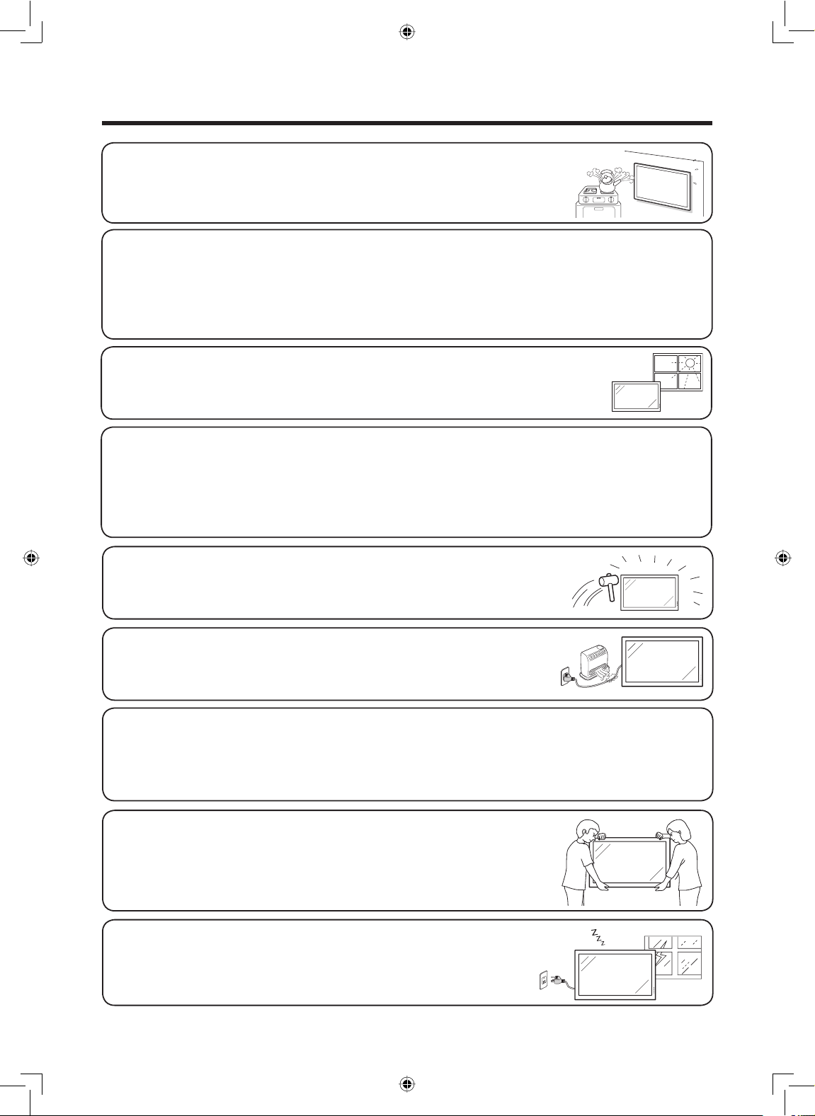
• Stand — Do not place the product on an unstable cart, stand, tripod or table. Placing the product on an
unstable base can cause the product to fall, resulting in serious personal injuries as well as damage to
the product. Use a cart, stand, tripod, bracket or table recommended by the manufacturer or sold with
the product. Do not allow the monitor to receive strong shocks or to strongly vibrate. When mounting
the product on a wall, be sure to follow the manufacturer’s instructions. Use only the mounting
hardware recommended by the manufacturer.
• Selecting the location — Select a place with no direct sunlight and good ventilation.
• Ventilation — The vents and other openings in the cabinet are designed for ventilation. Do not cover
or block these vents and openings since insufficient ventilation can cause overheating and/or shorten
the life of the product. Do not place the product on a bed, sofa, rug or other similar surface, since they
can block ventilation openings. This product is not designed for built-in installation; do not place the
product in an enclosed place such as a bookcase or rack, unless proper ventilation is provided or the
manufacturer’s instructions are followed.
• The Liquid Crystal panel used in this product is made of glass. Therefore, it can
break when the product is dropped or applied with impact. Be careful not to be
injured by broken glass pieces in case the panel breaks.
• Heat — The product should be situated away from heat sources such as
radiators, heat registers, stoves, or other products (including amplifiers)
that produce heat.
• The Liquid Crystal panel is a very high technology product with 2,073,600 pixels, giving you fine picture
details.
Occasionally, a few non-active pixels may appear on the screen as a fixed point of blue, green or red.
Also, if the screen is viewed from an acute angle there may be uneven colors or brightness.
Please note that this does not affect the performance of your product.
Precautions when transporting the monitor
• Be sure to always carry the monitor by two people holding it with two
hands — one hand on each side of the monitor.
• Do not hold onto the attached optional speakers when transporting the
monitor.
• Lightning — For added protection for this monitor equipment during a
lightning storm, or when it is left unattended and unused for long periods
of time, unplug it from the wall outlet. This will prevent damage to the
equipment due to lightning and power-line surges.
4
Page 7
IMPORTANT SAFETY INSTRUCTIONS
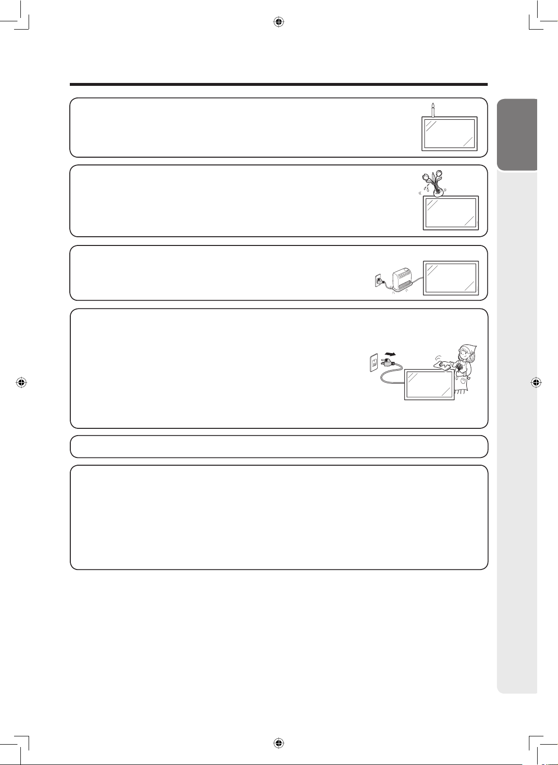
• To prevent fire, never place any type of candle or flames on the top or near the
monitor.
• To prevent fire or shock hazard, do not expose this product to dripping or splashing.
No objects filled with liquids, such as vases, should be placed on the product.
• To prevent fire or shock hazard, do not place the power cord under the monitor or
other heavy items.
• Turn off the power and unplug the power cord from the wall outlet before handling.
• Use a soft cloth and gently wipe the surface of the display panel. Using a hard cloth may scratch the
panel surface.
• Use a soft damp cloth to gently wipe the panel when it is really dirty.
(It may scratch the panel surface when wiped strongly.)
• If the panel is dusty, use an anti-static brush, which is commercially
available, to clean it.
• To protect the panel, do not use a dirty cloth, liquid cleaners or chemical
cloth to clean it, such materials may damage the panel surface.
• To clean the outer cabinet, use the same method. Do not use liquid or aerosol cleaners.
Introduction
• Do not display a still picture for a long time, as this could cause an afterimage to remain.
• Never rub or tap the monitor with hard objects.
• Please understand that SHARP CORPORATION bears no responsibility for errors made during use by
the customer or a third party, nor for any other malfunctions or damage to this product arising during
use, except where indemnity liability is recognized under law.
• This monitor and its accessories may be upgraded without advance notice.
• Do not use the monitor where there is a lot of dust, where humidity is high, or where the monitor may
come into contact with oil or steam, as this could lead to fi re.
• Ensure that no objects such as paper clips or pins enter the monitor as this could lead to fi re or electric
shock.
5
Page 8
IMPORTANT SAFETY INSTRUCTIONS
Fluorescent Tubes
• The fl uorescent tubes in this product have a limited lifetime.
* If the screen gets dark, fl ashes, or does not turn on, change the fl uorescent tubes with new exclusive
ones.
* For more information, please contact your product dealer.
• Because of the property of fl uorescent tubes, the screen may fl ash during the initial period of use. If this
happens, please turn off the power of the monitor and turn on again to confi rm operation.
6
Page 9
Contents
Introduction
DEAR SHARP CUSTOMER ........................... 1
IMPORTANT INFORMATION ......................... 1
Trademarks .................................................... 2
IMPORTANT SAFETY INSTRUCTIONS .......3
How to Access the PDF Operation
Manuals .......................................................... 8
SETUP MANUAL ....................................... 8
Accessories ................................................... 9
Part Names ................................................... 10
Preparation
How to Install the Monitor .......................... 13
Mounting precautions .............................. 13
Attaching the temporary stand ................ 13
Mounting the monitor on the wall ............. 14
Connecting Peripheral Equipment ............ 16
Connecting external speakers ................. 19
Connecting multiple monitors ..................19
Controlling the monitor by a computer..... 20
Connecting the Power Cord ....................... 21
Binding Cables ............................................21
Preparing the Remote Control ................... 22
Installing the batteries .............................. 22
Remote control operation range .............. 22
Operation
Turning the Monitor On/Off ........................ 23
Turning on the power ............................... 23
Turning off the power ............................... 23
Operating with the Remote Control ..........24
Switching the input mode ........................ 24
Adjusting the volume ............................... 24
Displaying the black screen and turning off
the sound temporarily ..............................24
Resize mode ............................................ 25
Auto Sync adjustment (Auto Sync) .......... 27
Freezing a moving image ......................... 27
Selecting AV mode ..................................27
Displaying an enlarged portion of
an image ..................................................27
Split-screen viewing ................................. 28
Using the remote control as the wireless
computer mouse ...................................... 29
Menu Operations ......................................... 30
Basic menu operations ............................30
List of menu items .................................... 31
Picture menu ............................................ 32
Audio menu .............................................. 34
Power Control menu ................................34
Setup menu .............................................. 35
Option menu ............................................39
Appendix
Troubleshooting .......................................... 45
For SHARP Assistance ...............................46
Specifi cations .............................................. 47
Index ............................................................. 52
Warranty ....................................................... 53
Français
CHER CLIENT SHARP................................. 55
INFORMATION IMPORTANTE .................... 55
CONSIGNES DE SÉCURITÉ
IMPORTANTES ............................................57
Comment accéder aux modes
d’emploi au format PDF ..............................61
Garanti e ........................................................ 62
Español
ESTIMADO CLIENTE DE SHARP ............... 63
INFORMACIÓN IMPORTANTE .................... 63
INSTRUCCIONES DE SEGURIDAD
IMPORTANTES ............................................65
Cómo acceder a los manuales de
manejo en formato PDF .............................. 69
Introduction
7
Page 10
How to Access the PDF Operation Manuals
PDF operation manuals in several languages are included in the CD-ROM. To utilize these manuals,
you need to install Adobe
Please download Adobe
Accessing the PDF manuals
For Windows®:
1 Insert the CD-ROM in the CD-ROM drive.
2 Double click the “My Computer” icon.
3 Double click the “CD-ROM” drive.
4 When you want to view the operation manual
1) Double click the “MANUALS” and the “M5200”
folder.
2) Double click the language (name of the folder)
that you want to view.
3) Double click the PDF fi le to access the
operation manual.
When you want to view the SETUP MANUAL
1) Double click the “SETUP” and the “M5200”
folder.
2) Double click the language (name of the folder)
that you want to view.
3) Double click the PDF fi le to access the SETUP
MANUAL.
®
Reader® on your computer (Windows® or Macintosh®).
®
Reader® from the Internet (http://www.adobe.com).
For Macintosh®:
1 Insert the CD-ROM in the CD-ROM drive.
2 Double click the “CD-ROM” icon.
3 When you want to view the operation manual
1) Double click the “MANUALS” and the “M5200”
folder.
2) Double click the language (name of the folder)
that you want to view.
3) Double click the PDF fi le to access the
operation manual.
When you want to view the SETUP MANUAL
1) Double click the “SETUP” and the “M5200”
folder.
2) Double click the language (name of the folder)
that you want to view.
3) Double click the PDF fi le to access the SETUP
MANUAL.
Note
• If the desired PDF fi le cannot be opened by double clicking the mouse, start Adobe® Reader® fi rst, then specify the desired
fi le using the “File”, “Open” menu.
SETUP MANUAL
Refer to the “SETUP MANUAL” contained on the supplied CD-ROM for details.
RS-232C Specifi cations and Commands ....................... 2
Setting up the Monitor Network Environment ............... 10
Controlling the Monitor via LAN .................................... 16
Setting up the Monitor Using RS-232C or Telnet ......... 21
Multi Screen Projection ................................................. 31
Troubleshooting ............................................................ 39
8
Page 11
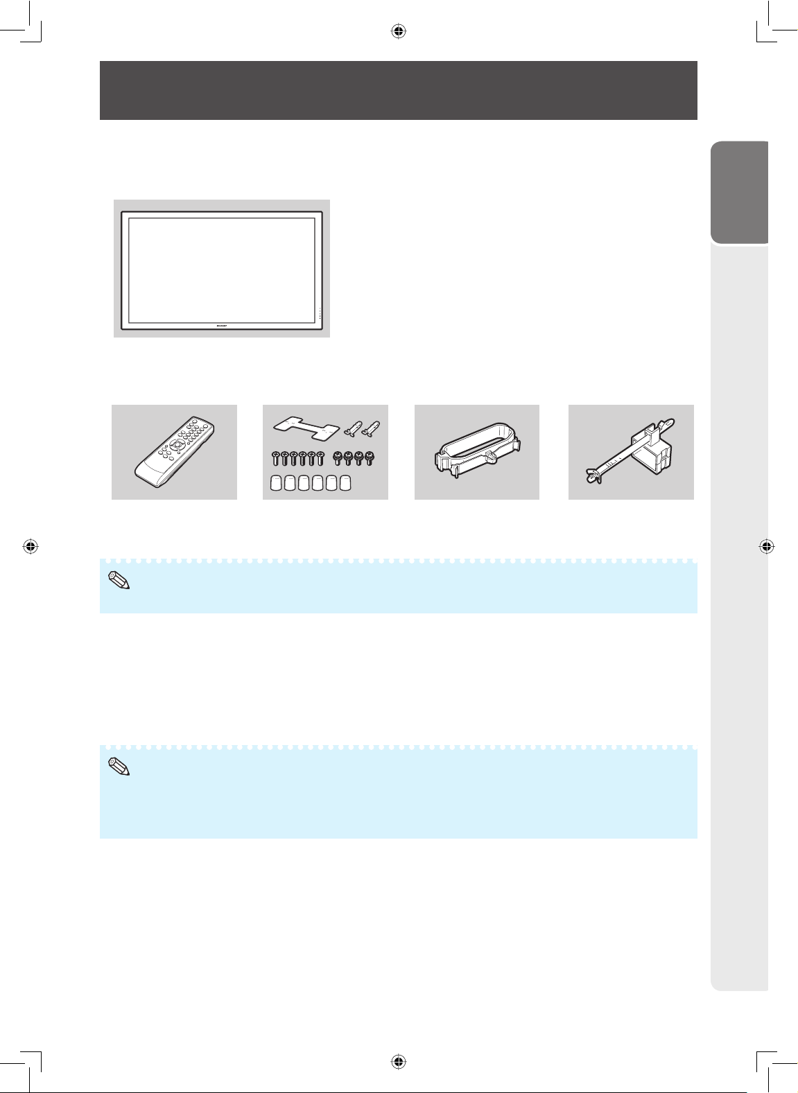
Accessories
Supplied accessories
If any component should be missing, please contact your dealer.
Liquid Crystal Display: 1
Power cord (Approx. 6 feet [1.8 m]): 1
<QACCDA007WJPZ>
R-6 battery (“AA” size, UM/SUM-3, HP-7 or similar): 2
CD-ROM: 1
<UDSKAA101WJZZ>
Operation manual: 1
<TINS-D532WJZZ>
Remote control: 1
<RRMCGA665WJSA> <LHLDWA173WJKZ>
* For environmental protection!
Do not dispose of batteries in household waste. Follow the disposal instructions for your area.
Temporary stand unit: 1 Cable clamp: 1
Power cord clamp: 1
<LHLDKA007WJKZ>
Introduction
Note
• Codes in “< >” are Replacement parts codes.
Optional accessories
The listed optional accessories are available for the LCD Monitor.
Please contact the nearest Sharp Authorized Dealer.
Speaker unit : AN-52SP2
Wall-mount bracket : AN-52AG4
USB remote receiver : AN-MR2
Note
• Some of the optional accessories may not be available depending on the region. Please check with your nearest Sharp
Authorized Dealer or Service Center.
• Additional optional accessories may be available in the near future. When purchasing, please read the newest catalog for
compatibility and check the availability.
9
Page 12
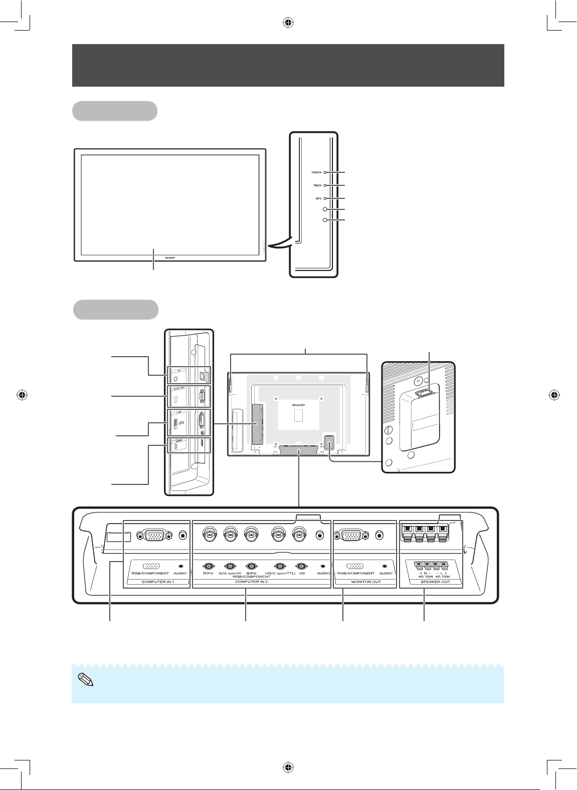
Front view
LCD panel
Rear view
Part Names
POWER indicator (See page 23.)
TIMER indicator (See page 43.)
OPC indicator (See page 33.)
OPC sensor (See page 33.)
Remote control sensor (See page 22.)
LAN
terminal
(See page 20.)
RS-232C
terminal
(See page 20.)
DVI IN
terminals
(See pages
16, 17 and 18.)
HDMI
terminal
(See page 17.)
COMPUTER IN 1 terminals
(
See pages 16, 17 and 18.
)
Handles
COMPUTER IN 2 terminals
(
See pages 16, 17 and 18.
)
MONITOR OUT terminals
(See page 18.)
AC input terminal
(See page 21.)
SPEAKER OUT terminals
(See page 19.)
Note
• The illustrations in this operation manual are for explanation purposes and may vary slightly from the actual operations.
10
Page 13
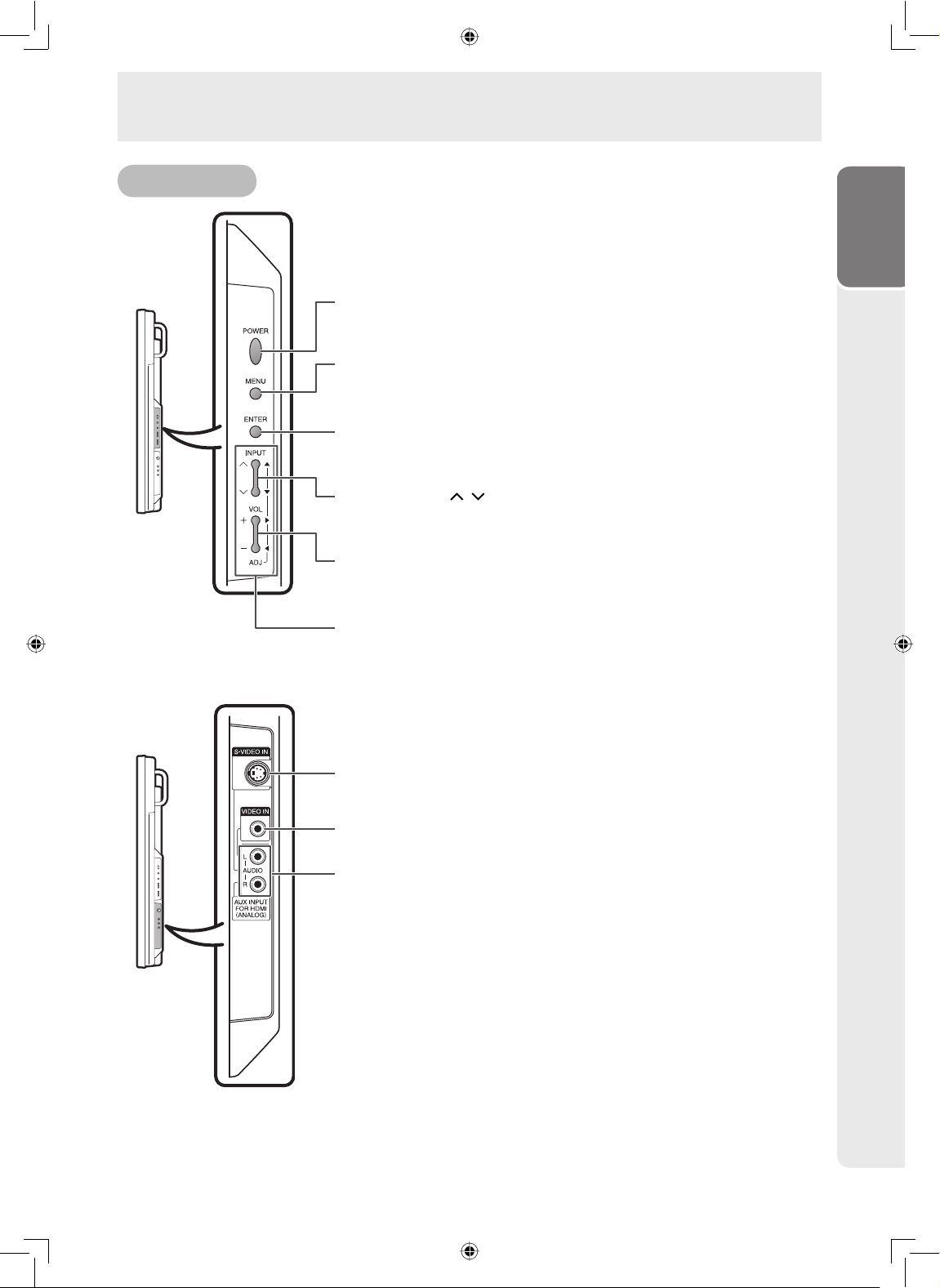
Part Names
Side view
POWER button
For turning the main power on.
(See page 23.)
MENU button
For displaying adjustment and setting screens.
(See page 30.)
ENTER button
For setting items selected or adjusted on the menu.
(See page 30.)
INPUT buttons (
For selecting the input mode.
(See page 24.)
VOL (Volume) buttons (+/–)
For adjusting the speaker sound level.
(See page 24.)
Adjustment buttons (▲/▼/◄/►)
For selecting and adjusting menu items.
(See page 30.)
/ )
Introduction
S-VIDEO IN terminal
(See pages 17 and 18.)
VIDEO IN terminal
(See pages 17 and 18.)
AUDIO terminals
(See page 18.)
11
Page 14
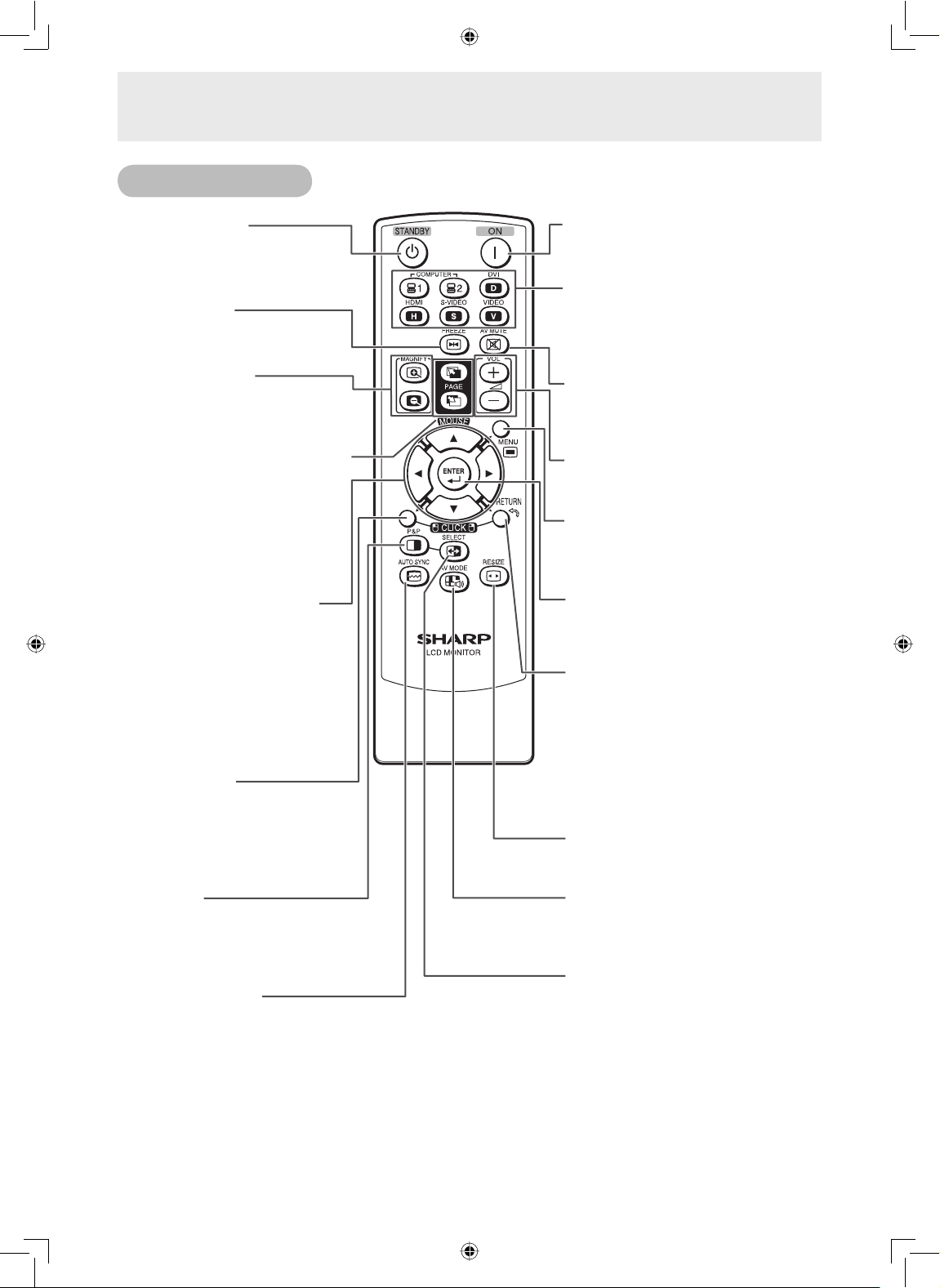
Part Names
Remote control
STANDBY button
For putting the monitor into
the standby mode.
(See page 23.)
FREEZE button
For freezing images.
(See page 27.)
MAGNIFY buttons
For enlarging/reducing part of
the image.
(See page 27.)
PAGE UP/PAGE DOWN buttons
Functions the same as the [Page
Up] and [Page Down] keys on
a computer keyboard using the
optional USB remote receiver
when the monitor is connected to
a computer.
(See page 29.)
Adjustment/MOUSE buttons
(▲/▼/◄/►)
• For selecting and adjusting menu
items.
(See page 30.)
• The computer cursor may be
moved using the optional USB
remote receiver when the monitor
is connected to a computer.
(See page 29.)
L-CLICK button
The Left button can be clicked using
the optional USB remote receiver
when the monitor is connected to a
computer.
(See page 29.)
ON button
For turning the power on.
(See page 23.)
COMPUTER 1, COMPUTER 2, DVI,
HDMI, S-VIDEO, VIDEO buttons
For switching to the respective input
modes.
(See page 24.)
AV MUTE button
For temporarily displaying a black
screen and turning off the sound.
(See page 24.)
VOL (Volume) buttons (+/–)
For adjusting the speaker sound level.
(See page 24.)
MENU button
For displaying adjustment and setting
screens.
(See page 30.)
ENTER button
For setting items selected or adjusted
on the menu.
(See page 30.)
RETURN/R-CLICK button
• For returning to the previous menu
screen during menu operations.
(See page 30.)
• The Right button can be clicked
using the optional USB remote
receiver when the monitor is
connected to a computer.
(See page 29.)
RESIZE button
For switching the picture size.
(See page 25.)
P&P button
For setting the split-screen picture
mode. Press P&P again to return to
normal view.
(See page 28.)
AUTO SYNC button
For automatically adjusting images when
connected to a computer.
(See page 27.)
12
AV MODE button
For selecting appropriate settings for
picture and audio.
(See page 27.)
SELECT button
For selecting either screen to be active
in split-screen mode.
(See page 28.)
Page 15
How to Install the Monitor
Mounting precautions
• Mounting the monitor on the wall requires special expertise and the work must be performed by an
authorized SHARP dealer. You should never attempt to perform any of this work yourself. Our company
will bear no responsibility for accidents or injuries caused by improper mounting or mishandling.
• This monitor is designed to be installed on a concrete wall or pillar. Reinforced work might be necessary
for some materials such as plaster / thin plastic board / wood before starting installation.
This monitor and bracket must be installed on a wall which can endure at least 4 times or more the weight
of the monitor. Install by the most suitable method for the material and the structure.
• This monitor can not be installed in a vertical orientation.
• Since the monitor is heavy, consult your dealer before installing, removing or moving the monitor.
• When installing, removing or moving the monitor, ensure that this is carried out by at least 2 people.
• When moving the monitor, be sure to hold it with the handles both on the rear and the unit bottom. Do not
hold the LCD panel. This may cause product damage, failure, or injury.
• This monitor should be used at an ambient temperature between 32°F (0°C) and 104°F
(40°C). Provide enough space around the monitor to prevent heat from accumulating inside.
• Do not block any ventilation openings. If the temperature inside the monitor rises, this could lead to a
malfunction.
• Do not place the monitor on a device which generates heat.
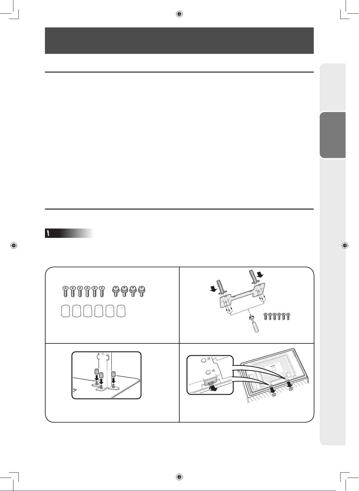
Attaching the temporary stand
Before performing work spread cushioning over the base area to lay the monitor on. This will prevent it from
being damaged.
Preparation
Caution
• Please note that the temporary stand is for temporary use only until the monitor is properly mounted.
• Attach the stand in the correct direction.
• Be sure to follow the instructions. Incorrect installation of the stand may result in the monitor falling over.
12
Confi rm that there are 10 screws and 6 caps
supplied with the stand unit.
Assemble the stand using the 6 screws.
34
Put the caps on the screws that have been
screwed into the stand.
Remove the protective covers from the underside
of the monitor.
13
Page 16
How to Install the Monitor
0°/5°/10°/15°/20°
56
Insert the stand into the openings on the
underside of the monitor.
Note
• To detach the stand, perform the steps in reverse order.
• Store the protective covers. You will need them after detaching the stand.
Insert and tighten the screws into the 4 holes on
the rear of the monitor.
Mounting the monitor on the wall
Handling and precautions with the wall-mounted monitor
• You can mount the monitor on the wall using the optional AN-52AG4 bracket.
• For details, refer to the instructions supplied with the optional AN-52AG4 bracket.
Caution
• This monitor should be mounted on the wall only with the AN-52AG4 (SHARP) wall-mount bracket. The
use of other wall-mount brackets may result in an unstable installation and may cause serious injuries.
• Installing the monitor requires special skill that should only be performed by qualifi ed service personnel.
Customers should not attempt to do the work themselves. SHARP bears no responsibility for improper
mounting or mounting that results in accident or injury.
Using a SHARP recommended bracket to mount the monitor
• You can ask a qualifi ed service professional about using a SHARP recommended AN-52AG4 bracket to
mount the monitor to the wall.
• Carefully read the instructions that come with the bracket before beginning work.
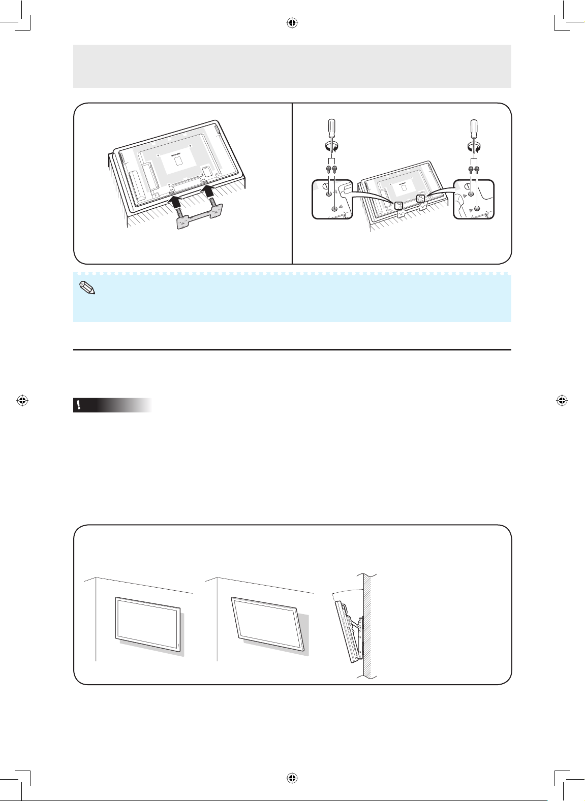
Hanging on the wall
AN-52AG4 wall-mount bracket. (See the bracket instructions for details.)
About setting the monitor angle
14
Vertical mounting Angular mounting
• The center of the display:
5¼ inch (136 mm) under
the “A” position.
• Refer to the operation
manual of AN-52AG4 for
details.
AN-52AG4
Page 17
How to Install the Monitor
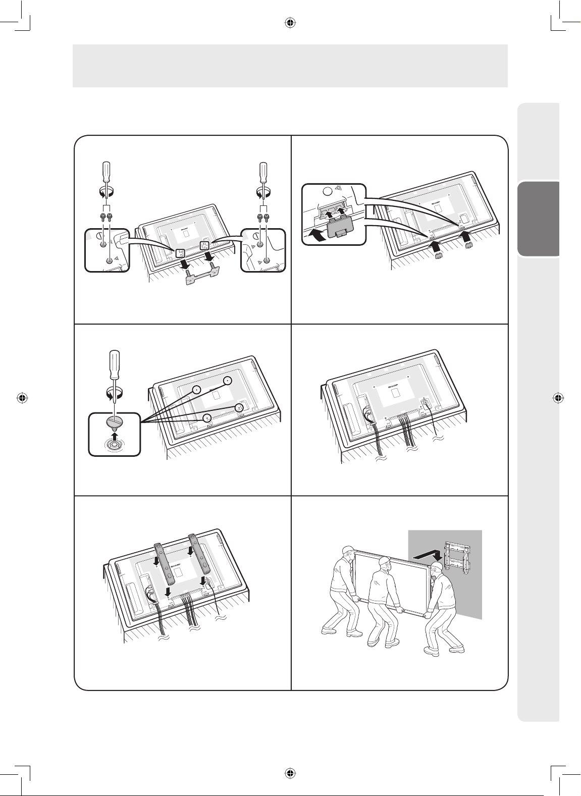
Mounting the monitor on the wall
Attach the monitor to the wall-mount brackets according to the procedure below.
12
Use the protective cover to prevent dust from
Unfasten the 4 screws used to secure the stand in
place.
entering the underside of monitor where the stand
has been detached.
Preparation
3
Detach the 4 caps at the 4 locations on the rear of
the monitor.
5
4
Connect and bind the power cord and terminal
cables.
6
Attach the wall-mount brackets (L/R).
Set the monitor on the wall.
15
Page 18
Connecting Peripheral Equipment
Caution
• Be sure to turn off the power and disconnect the plug from the power outlet before connecting/
disconnecting cables. Also, read the manual of the equipment to be connected.
• Be careful not to mix up the input terminal with the output terminal when connecting cables. Mixing up the
input and output terminals may cause malfunctions and other problems.
• After making all connections, turn on the monitor and then the other pieces of equipment. When
connecting a computer, ensure that it is the last equipment to be turned on after all the connections are
made.
• You may need other cables or connectors not listed below.
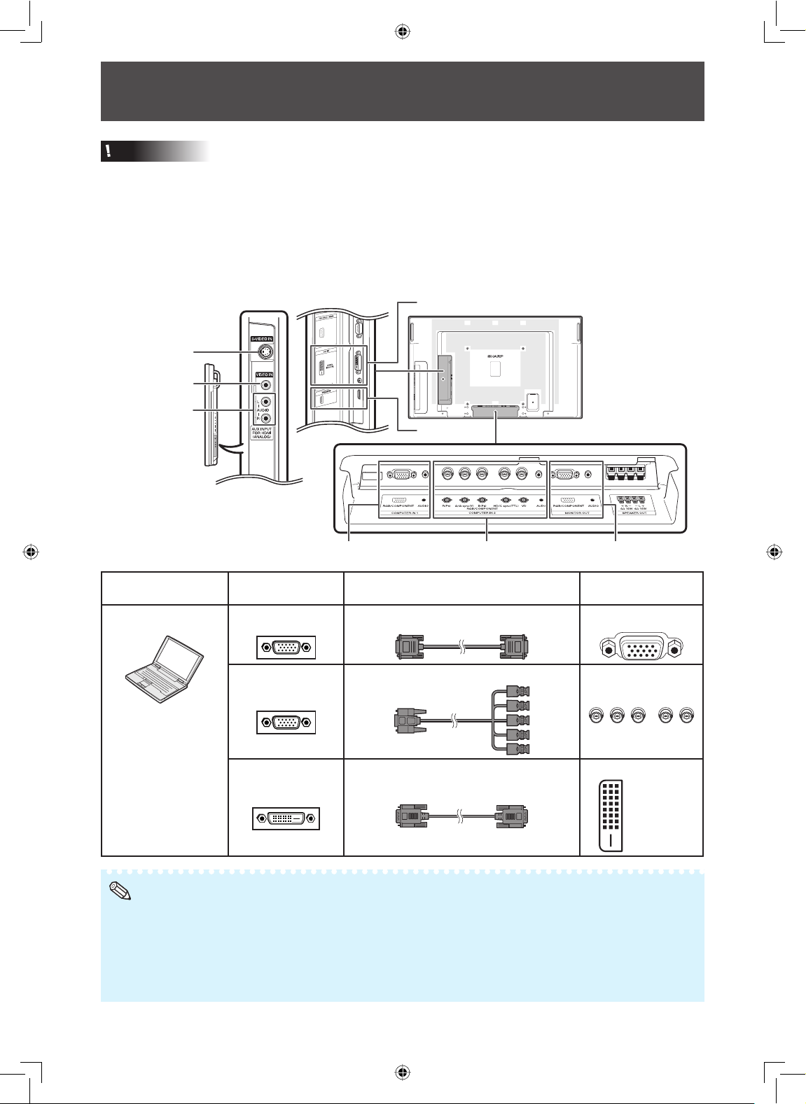
DVI IN
S-VIDEO IN
VIDEO IN
AUDIO
HDMI
COMPUTER IN 1 COMPUTER IN 2
Equipment
Computer RGB output
Note
• Images may not be displayed properly depending on the computer (graphics board) to be connected.
• See page 49 “Computer compatibility chart” for a list of computer signals compatible with the monitor.
Use with computer signals other than those listed may cause some of the functions to not work.
• A Macintosh adaptor may be required for use with some Macintosh computers. Contact your nearest Macintosh Dealer.
• Depending on the computer you are using, an image may not be displayed unless the computer’s external output port is
switched on (e.g. Press “Fn” and “F5” keys simultaneously when using a SHARP notebook computer). Refer to the specifi c
instructions in your computer’s operation manual to enable your computer’s external output port.
Terminal on connected
equipment
terminal
RGB output
terminal
DVI digital output
terminal
RGB cable COMPUTER IN 1
5 BNC to 15-pin D-sub cable COMPUTER IN 2
DVI Digital cable DVI IN
Cable (commercially available)
MONITOR OUT
Terminal on the
monitor
DVI-D
(HDCP)
16
Page 19
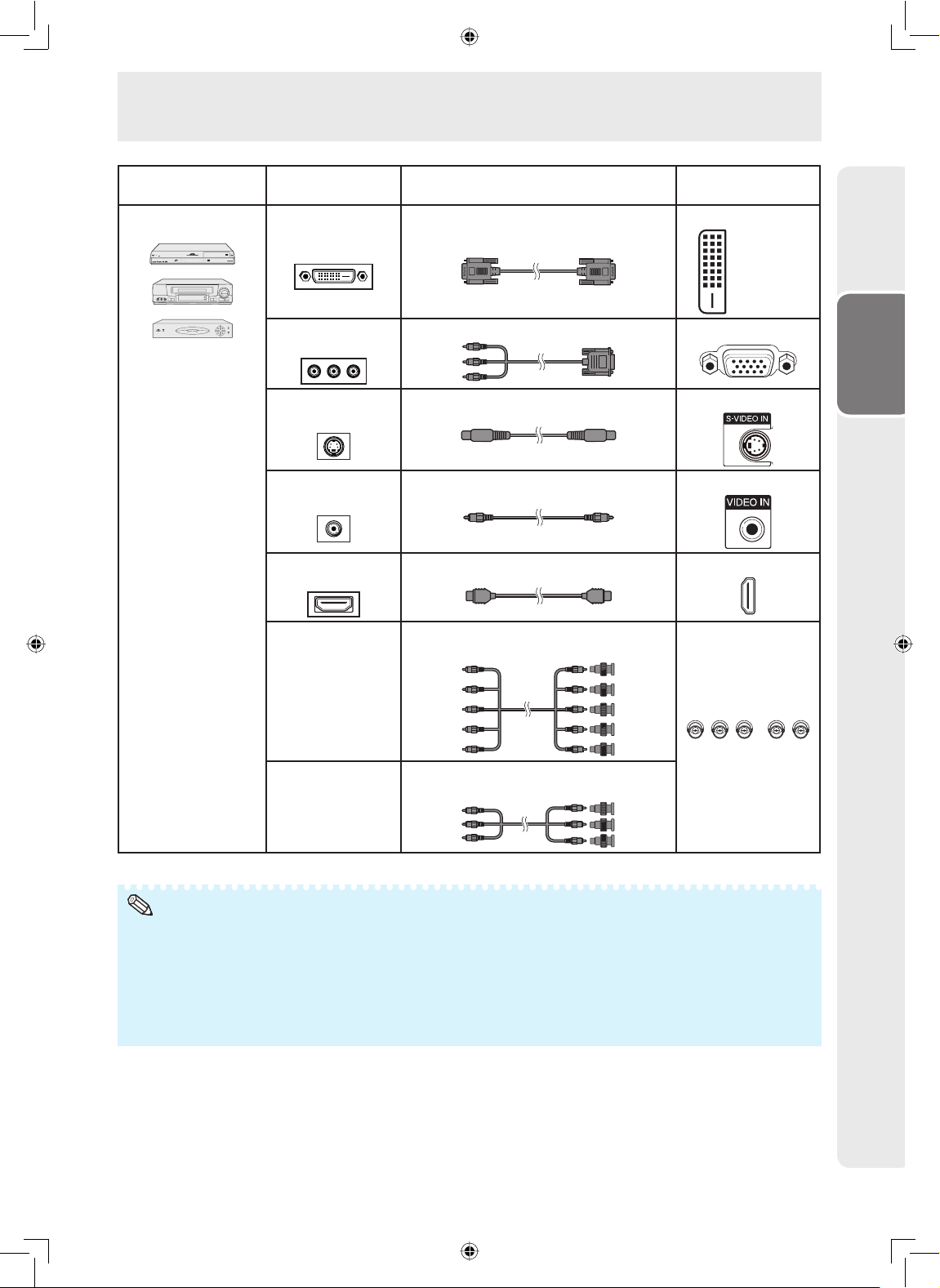
Connecting Peripheral Equipment
Equipment
Video equipment
Terminal on connected
equipment
DVI digital output
DVI Digital cable DVI IN
terminal
Component video
3 RCA to mini D-sub 15 pin cable COMPUTER IN 1
output terminal
S-video output
S-video cable S-VIDEO IN
terminal
Video output
Video cable VIDEO IN
terminal
HDMI output
HDMI cable HDMI
terminal
RGB output
terminal
5 RCA RGB cable
BNC to RCA adaptors
Cable (commercially available)
Terminal on the
monitor
DVI-D
(HDCP)
Preparation
COMPUTER IN 2
Component
video output
BNC to RCA adaptors
Component video cable
terminal
Note
• Depending on specifi cations of video equipment or HDMI to DVI digital cable, the signal transmission may not work properly.
(The HDMI specifi cation does not support all connections to video equipment that has HDMI digital output terminal using
HDMI to DVI digital cable.)
• For details on compatibility for connection, see support information on DVI connection provided by the video equipment
manufacturer.
• When you connect video equipment with a 21-pin RGB output (Euro-scart) to the monitor, use a commercially available cable
that fi ts in the monitor terminal you want to connect.
• The monitor does not support RGBC signals via the Euro-scart.
17
Page 20
Connecting Peripheral Equipment
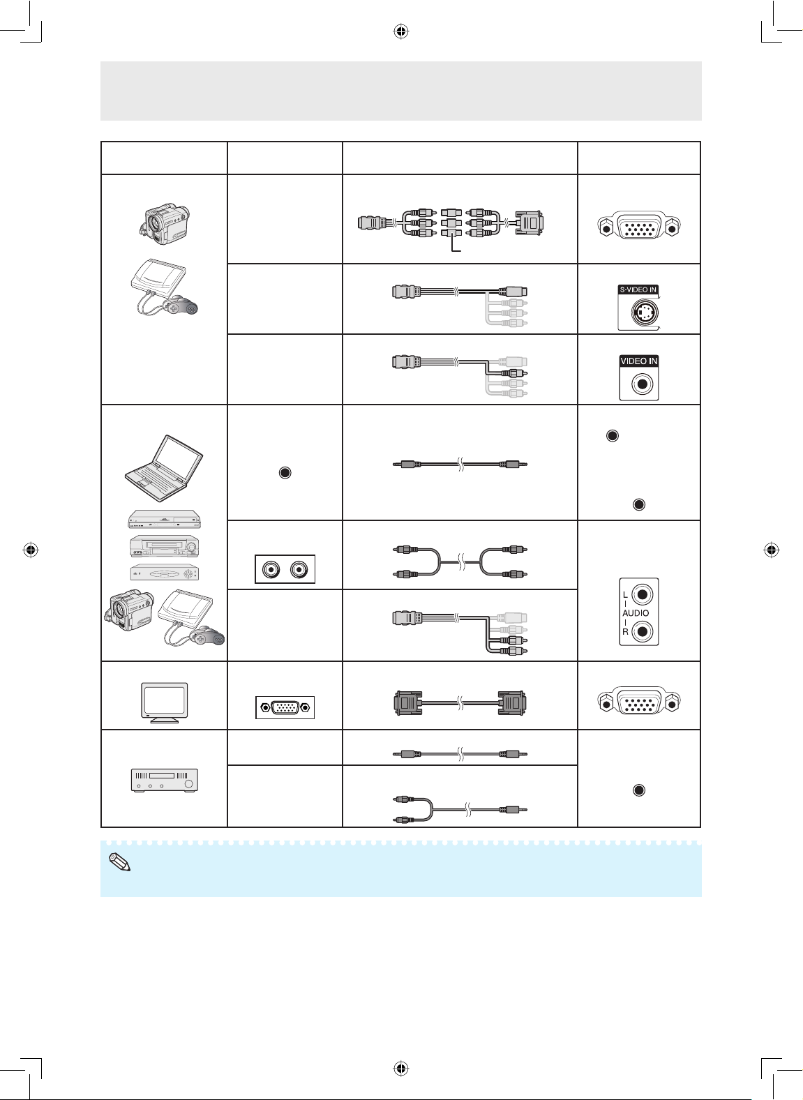
Equipment
Camera/Video game
Audio equipment ø3.5 mm audio
Terminal on connected
equipment
Component
video output
terminal
S-video output
terminal
Video output
terminal
output terminal
RCA audio output
terminal
Cable (commercially available)
Cables for a camera or a video game/
3 RCA to mini D-sub 15 pin cable
RCA adaptor plug
Cables for a camera or a video game S-VIDEO IN
Cables for a camera or a video game VIDEO IN
ø3.5 mm stereo or mono audio cable AUDIO (for DVI IN)
RCA audio cable AUDIO
Terminal on the
monitor
COMPUTER IN 1
AUDIO
AUDIO
(for COMPUTER IN 1)
(for COMPUTER IN 2)
(for S-VIDEO IN)
(for VIDEO IN)
Audio output
terminal
Monitor RGB input
terminal
Amplifi er ø3.5 mm audio
input terminal
RCA audio input
terminal
Note
• When using the ø3.5 mm mono audio cable, the volume level will be half of when using the ø3.5 mm stereo audio cable.
MONITOR OUT terminals
• Audio and images from equipment connected to the COMPUTER IN 1 or COMPUTER IN 2 terminals can
be output from the MONITOR OUT terminals.
Cables for a camera or a video game
RGB cable MONITOR OUT
ø3.5 mm stereo or mono audio cable AUDIO
(for MONITOR OUT)
ø3.5 mm stereo minijack to RCA audio
cable
18
Page 21
Connecting Peripheral Equipment
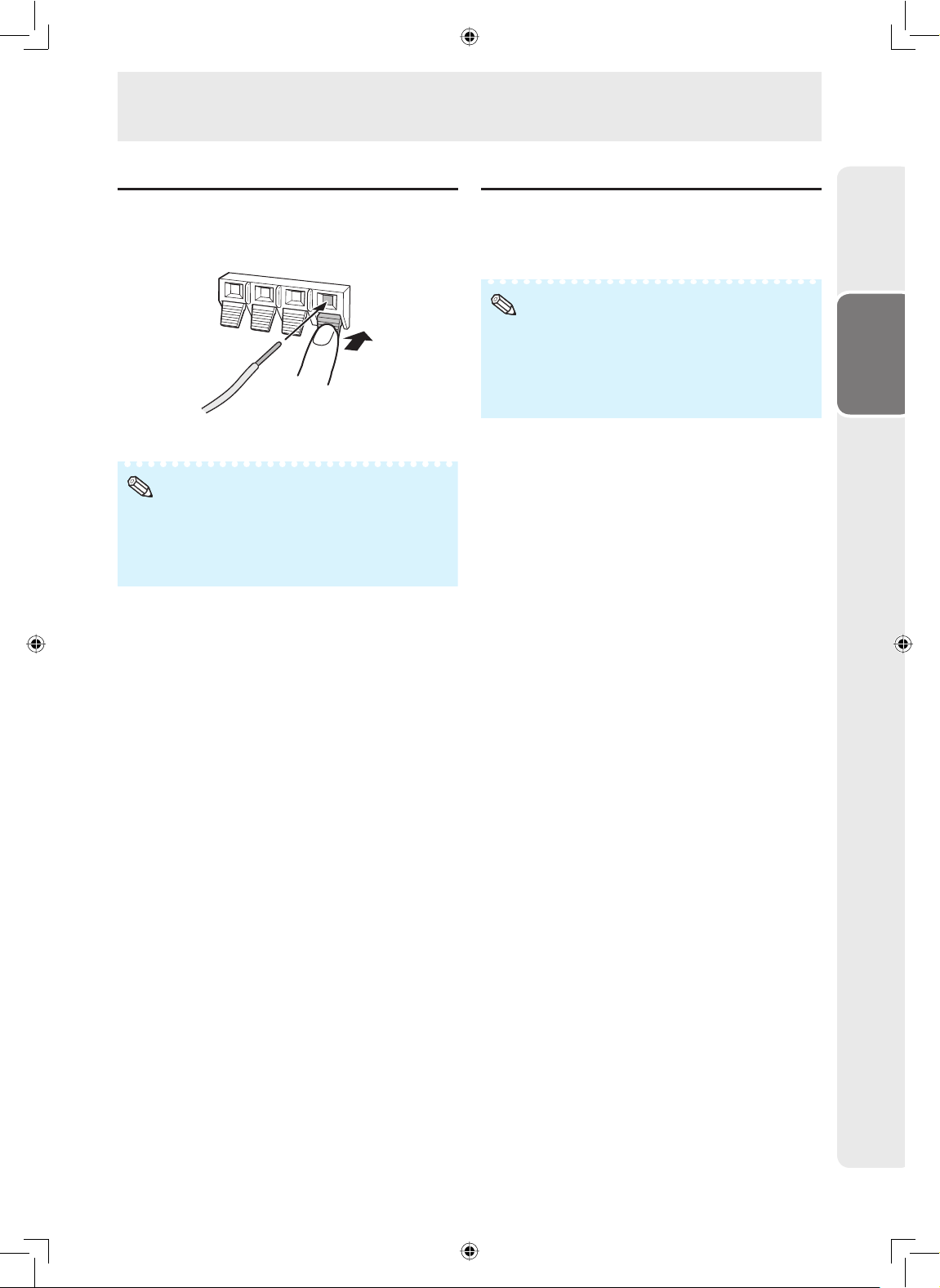
Connecting external speakers
Be sure to use external speakers with an impedance
of 4 Ω and a rated input of at least 15 W.
While pushing the tab, insert the tip of the cable.
1
Release the tab.
2
Note
• Be sure to connect the + and - terminals and the left and
right speakers properly.
• Avoid short circuiting the + and - terminals.
• It is recommended that you use the optional Sharp
speaker unit (AN-52SP2) for external speakers.
Connecting multiple monitors
You can connect multiple monitors by using the
RGB/COMPONENT input terminals (COMPUTER IN 1
or COMPUTER IN 2) and the RGB/COMPONENT
output terminals (MONITOR OUT).
Note
• The length of the signal cables or surrounding environment
may affect the image quality.
• When connecting multiple monitors, the screen may not
display properly. In this case, turn off the power to all the
monitors connected and then turn the power on again.
• For details, refer to the “SETUP MANUAL”.
Preparation
19
Page 22
Connecting Peripheral Equipment
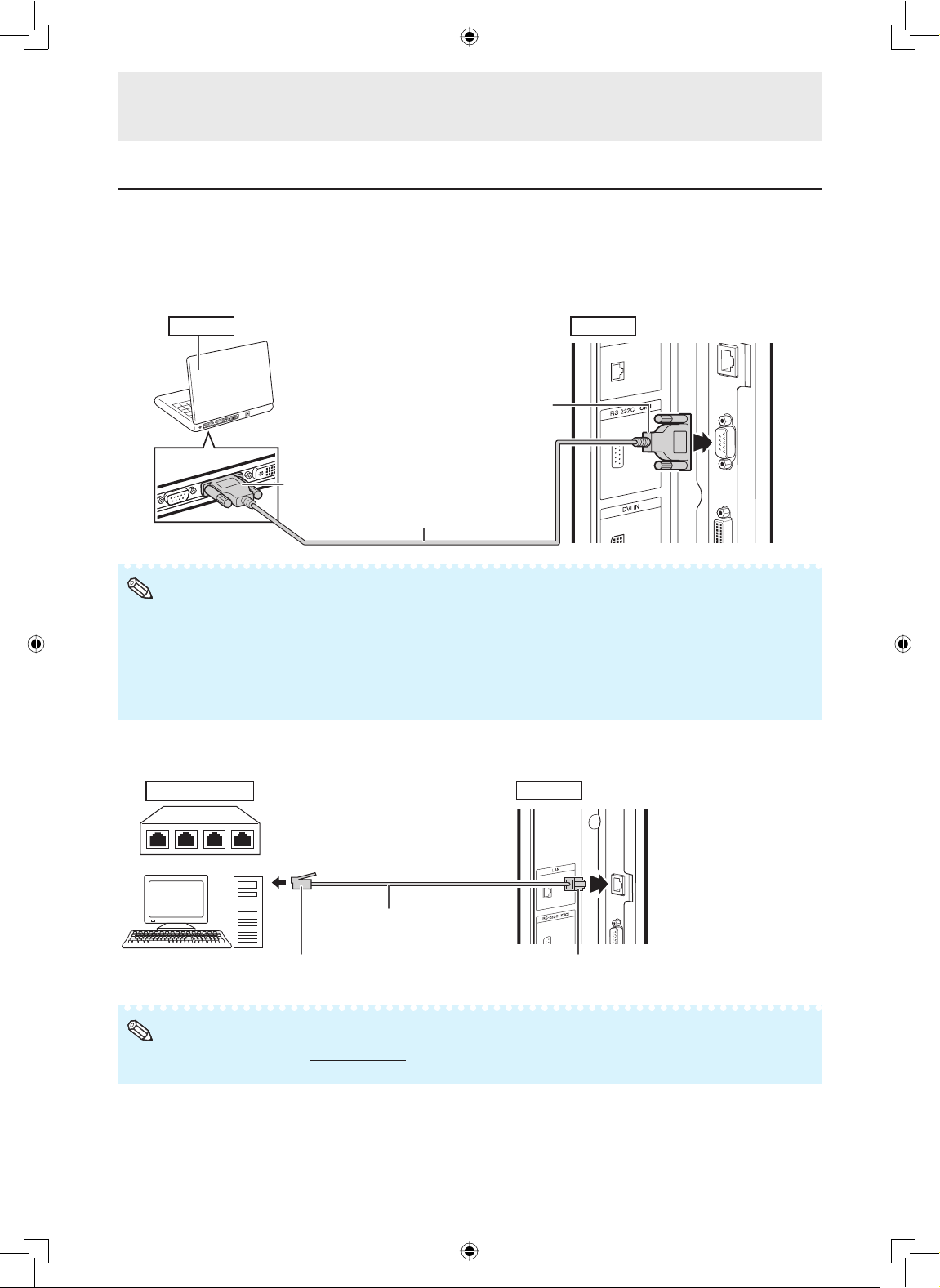
Controlling the monitor by a computer
When the RS-232C terminal on the monitor is connected to the RS-232C serial terminal on the computer,
or when the LAN terminal on the monitor is connected to the LAN terminal on the computer, the computer
can be used to control the monitor. Refer to the “SETUP MANUAL” contained on the supplied CD-ROM for
details.
When connecting to a computer using an RS-232C serial control cable
Computer Rear view
To RS-232C terminal
To RS-232C terminal
RS-232C serial control cable
(cross type, commercially available)
Note
• The RS-232C function may not operate if your computer terminal is not correctly set up. Refer to the operation manual of the
computer for details.
• Refer to “SETUP MANUAL” contained on the supplied CD-ROM for the RS-232C specifi cations and commands.
• Do not connect the RS-232C cable to a terminal other than the RS-232C terminal on the computer. This may damage your
computer or monitor.
• Do not connect or disconnect an RS-232C serial control cable to or from the computer while it is on. This may damage your
computer.
When connecting to the LAN terminal using a LAN cable
Hub or computer
Note
• When connecting to a hub, use
• When connecting to a computer, use
straight-through
LAN cable
(Category 5 type,
commercially available)
cross-over
Category 5 (CAT.5) type cable (commercially available).
Category 5 (CAT.5) type cable (commercially available).
Rear view
To LAN terminalTo LAN terminal
20
* To ensure safety, do not
connect the LAN terminal
with any cables such as
a telephone line that may
cause excessive voltage.
Page 23
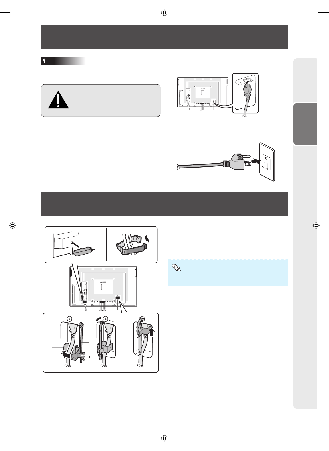
Connecting the Power Cord
Caution
• Do not use a power cord other than the one
supplied with the monitor.
Be sure to use a power outlet of
AC 120 V (60 Hz).
Using power supply other than the
one specified may cause fire.
• Place the monitor close to the AC outlet, and
keep the power plug within reach.
• This product must only be connected to an AC
120 V, 60 Hz, grounded (3-prong) outlet.
Connecting it to any other kind of outlet will
damage the product and invalidate the warranty.
Binding Cables
Plug the power cord (supplied) into the AC input
1
terminal.
Plug the power cord (supplied) into the AC power
2
outlet.
Preparation
12 3
Hole
for
the
power
cord
clamp
Fastened
part
Band
Power
cord
clamp
Attaching the cable clamp
The cables connected to the terminals on the back
of the monitor can be neatly bundled using the
supplied cable clamp as shown in the illustration.
Note
• A cable clamp cannot be easily removed once it is
attached.
Fastening the power cord
The power cord can be fastened using the supplied
power cord clamp. This will prevent the power cord
from being disconnected accidentally.
Attach the supplied power cord clamp to the
1
power cord, making sure the power cord clamp is
circular hole-side down.
Insert the tip of the band into the hole for the
2
power cord clamp.
While holding the tail of the band, slide the
3
fastened part toward the AC input terminal.
21
Page 24

Preparing the Remote Control
Installing the batteries
Pull down the tab on the cover
1
and remove the cover towards
the direction of the arrow.
Insert the batteries.
2
• Insert the batteries making sure
the polarities correctly match
+
the
and - marks inside the
Insert the lower tab of the
3
cover into the opening, and
lower the cover until it clicks in
place.
battery compartment.
Incorrect use of the batteries may cause them to leak or explode. Please follow the
precautions below.
Caution
• Danger of explosion if battery is incorrectly replaced.
Replace only with alkaline or manganese batteries.
• Insert the batteries making sure the polarities correctly match the
• Batteries of different types have different properties, therefore do not mix batteries of different types.
• Do not mix new and old batteries.
This may shorten the life of new batteries or may cause old batteries to leak.
• Remove the batteries from the remote control once they have run out, as leaving them in can cause them to leak.
Battery fl uid from leaked batteries is harmful to skin, therefore ensure you wipe them fi rst and then remove them using a cloth.
• The batteries included with this monitor may run down in a short period, depending on how they are kept. Be sure to replace them
as soon as possible with new batteries.
• Remove the batteries from the remote control if you will not be using the remote control for a long time.
• Comply with the rules (ordinance) of each local government when disposing of worn-out batteries.
+
and - marks inside the battery compartment.
Remote control operation range
The operation range of the remote control is approx.
16.4 feet (5 m) at an angle of approx 30° from the
center to the top/bottom/right/left of the remote
control sensor.
Note
• Do not expose the remote control to shock by dropping or
stepping on it. This could lead to a malfunction.
• Do not expose the remote control to liquids, and do not
place it in an area with high humidity.
• The remote control may not work properly if the remote
control sensor is under direct sunlight or strong lighting.
• Objects between the remote control and the remote control
sensor may prevent proper operation.
• Replace the batteries when they run low as this may
shorten the remote control’s operation range.
• If a fl uorescent light is illuminated near the remote control,
it may interfere with proper operation.
• Do not use it with the remote control of other equipment
such as air conditioner, stereo components, etc.
30º
30º 30º
30º
Remote control
sensor
16.4 feet (5 m)
22
Page 25

Turning the Monitor On/Off
Turning on the power
Press POWER on the monitor.
• POWER indicator (Green): The monitor is on.
• After turning the power “ON” by pressing POWER
on the monitor, you can turn the power ON by
pressing ON on the remote control.
POWER button
POWER indicator
Turning off the power
button
Press STANDBY on the remote control.
• The monitor enters standby mode.
• The POWER indicator on the monitor changes
from green to red.
Press POWER on the monitor.
• The POWER indicator on the monitor turns off.
• When the monitor is turned off by POWER on
the monitor, you cannot turn on the power by
pressing ON on the remote control.
POWER indicator
Lighting (Green) Power ON
Lighting (Red) Standby
Lights off Power OFF
Flashing
(Orange)
Flashing
(Green)
When “Power On Delay” function
is activated.
Input signal standby (when
“Power Management” is set to
“Mode2” in the Power Control
menu.)
ON buttonSTANDBY
Operation
Caution
• When switching the POWER, ON or STANBY
buttons off and back on, always wait for at least
5 seconds. A short interval may result in a
malfunction.
Note
• If you are not going to use this monitor for a long period
of time, be sure to remove the power cord from the AC
outlet.
• Minor power is consumed when the unit is in standby
mode.
23
Page 26

Operating with the Remote Control
Switching the input mode
Select the appropriate input mode for the connected
equipment.
Press COMPUTER (1/2), DVI, HDMI, S-VIDEO or
VIDEO to select the input mode.
• When you press INPUT on the monitor, the
INPUT list appears.
Press ▲/▼ to switch the input mode.
Adjusting the volume
Press VOL +/– to adjust the volume.
• You can also adjust the volume using VOL +/– on
the monitor.
25
Note
• Pressing
• Pressing
• You can set the volume to different levels for each input
source.
• To adjust sound via the audio output terminal (MONITOR
OUT), set “Audio Output” to “VAO” in the “Option” menu.
(See page 40.)
VOL–
will lower the volume.
VOL+
will raise the volume.
COMPUTER (1/2), DVI, HDMI,
S-VIDEO, VIDEO buttons
AV MUTE button
VOL (Volume) buttons (+/-)
Displaying the black screen
and turning off the sound
temporarily
Press AV MUTE to temporarily display a black
screen and turn off the sound.
AV MUTE
Note
• Pressing
AV MUTE
again will turn the image back on.
24
Page 27

Operating with the Remote Control
Resize mode
This function allows you to modify or customize the Resize mode to enhance the input image. Depending on
the input signal, you can choose a desired image.
Press RESIZE.
1
• The Resize mode menu appears.
• The menu lists the Resize mode options
selectable for the type of signal currently
received.
Resize
Normal
Zoom 14:9
S.Stretch
Full
Cinema 16:9
Cinema 14:9
Press RESIZE or ▲/▼ while the Resize mode menu is displayed on the screen.
2
Note
• You can also set the Resize mode from the “Option” menu. (See page 42.)
RESIZE buttonRESIZE button
Operation
AV input
Normal
Zoom 14:9
S. Stretch
Full
Selectable items Description
For 4:3 “standard” pictures. A side bar appears on each side.
Normal
For 14:9 letterbox pictures. A thin side bar appears on each
side, and the top and bottom of the image may be cut off
depending on the input signal.
Zoom 14:9
Only the ends of the image are stretched horizontally.
S. Stretch
For 16:9 squeeze pictures.
Full
25
Page 28

Operating with the Remote Control
Selectable items Description
Cinema 16:9
Cinema 16:9
For 16:9 letterbox pictures. The top and bottom of the image
may be cut off depending on the input signal.
Cinema 14:9
For 14:9 letterbox pictures. The top and bottom of the image
may be cut off depending on the input signal.
Cinema 14:9
Dot by Dot Display an image with the same number of pixels on the
screen (only when receiving 1080i/1080p signal via
component or HDMI terminals).
Computer input
Selectable items Description
Normal
Keeps the original aspect ratio in a full screen display.
Normal
Full
An image fully fills the screen.
Full
Dot by Dot
Detects the resolution of the signal and displays an image with
the same number of pixels on the screen.
Dot by Dot
Displays an image that overlaps the screen when a signal of
greater resolution than the size of the screen is input.
Note
• When using the Resize function to select an image size with a different aspect ratio to a TV program or video image, the
image will look different from its original appearance. Keep this in mind while choosing an image size.
• The use of the Resize or split-screen function to compress or stretch the image for commercial purposes/public displays in a
café, hotel, etc. may be an infringement of copyright protected by law for copyright holders. Please use caution.
• While watching non-widescreen images (4:3), if you use the Resize function to fi ll the screen, parts of the outer edge of the
image will be cut off or distorted. To watch original images as the producers intended, set the Resize mode to “Normal”.
• When “Multi Screen” is set, the Resize mode is fi xed to “Full”.
• When split-screen display is selected, the Resize mode cannot be changed.
• When playing commercial software, parts of the image (like subtitles) may be cropped. In this case select the optimal screen
size using the Resize function of this monitor. With some software, there may be noise or distortion at the edges of the screen.
This is due to the characteristics of the software, and is not a malfunction.
• Depending on the original image size, black bands may remain at the edges of the screen.
26
Page 29

Operating with the Remote Control
FREEZE
button
MAGNIFY
buttons
RETURN
button
AUTO SYNC
button
AV MODE
button
Auto Sync adjustment
(Auto Sync)
“Clock”, “Phase”, “H-Position”, and “V-Position” are
automatically adjusted.
Press AUTO SYNC.
• You can also perform Auto Sync adjustment from
the “Setup” menu.
Displaying an enlarged portion
of an image
Graphs, tables and other portions of images can
be enlarged. This is helpful when providing more
detailed explanations.
Press MAGNIFY.
1
• Enlarges the image.
• Pressing
reduces the image.
Note
×1 ×2 ×3 ×4 ×9 ×16 ×36
• You can change the location of the enlarged
image using ▲/▼/◄/►.
Press RETURN to cancel the operation.
2
• The magnifi cation then returns to ×1.
or MAGNIFY enlarges or
Press .
Press .
Operation
Freezing a moving image
Press FREEZE.
1
• The image is frozen.
Press FREEZE again to return to the moving
2
image from the currently connected device.
Note
• The still image automatically goes out after 30 minutes.
Selecting AV mode
You can select the appropriate mode for the image,
such as movie or video game.
Press AV MODE.
• When pressing AV MODE, the AV mode changes
in the following order:
Standard Presentation Movie Game sRGB
Note
• See page 32 for details on AV mode.
• “sRGB” is displayed only when RGB signal is input.
Note
• The selectable magnifi cations differ depending on the
input signal.
• In the following cases, the image will return to the normal
size (×1).
– When switching the input mode.
RETURN
– When
– When the input signal is changed.
– When the input signal resolution and refresh rate
(vertical frequency) change.
– When the Resize mode is changed.
has been pressed.
27
Page 30

Operating with the Remote Control
Split-screen viewing
You can display two pictures on the screen simultaneously.
COMPUTER (1/2), DVI,
HDMI, S-VIDEO, VIDEO
buttons
P&P button
SELECT button
Press P&P.
1
• Split-screen appears.
• The current input is moved to the left side screen display and surrounded by a blue frame.
• The other input appears on the right side screen display.
35
30
25
20
15
10
5
123456789101112
Press SELECT to set either screen to be active.
2
2345678910
• The active screen, surrounded by a blue frame, has sound output.
Press COMPUTER (1/2), DVI, HDMI, S-VIDEO or VIDEO to select another input source on the active
3
screen.
• A selected image appears.
Press P&P to exit split-screen.
4
Note
• This function does not work under the following input conditions:
1) Two pictures from the same source.
2) Two pictures from HDMI and DVI.
3) Pictures from S-VIDEO or VIDEO on the right side screen are displayed.
• While split-screen is displayed, the FREEZE function does not work.
28
Page 31

Operating with the Remote Control
Using the remote control as the wireless computer mouse
The USB remote receiver (optional, AN-MR2) makes it possible to operate the monitor with the remote
control. For details, see the operation manual of the receiver.
Computer
USB r
To Monitor
To USB terminalTo PC
emote receiver
(optional, AN-MR2)
RGB, DVI or HDMI cable
(commercially available)
The mouse pointer can be operated in the following way after it is connected.
When moving the cursor:
Press Adjustment/MOUSE (▲/▼/◄/►).
When left-clicking:
Press L-CLICK.
When right-clicking:
Press R-CLICK.
When your computer supports only a one-click
mouse (such as Macintosh):
Press L-CLICK or R-CLICK.
L-CLICK and R-CLICK have common function.
When using [Page Up] or [Page Down]:
Same as the [Page Up] and [Page Down] keys on a
computer keyboard.
Press PAGE UP or PAGE DOWN.
PAGE UP/
PAGE DOWN buttons
Adjustment/MOUSE
buttons (
R-CLICK button
L-CLICK button
/ / / )
Operation
Note
• This function only works with the Microsoft® Windows® OS and Mac OS®. However, this function does not work with the
following operation systems that do not support USB.
– Versions earlier than Windows
– Versions earlier than Windows
– Versions earlier than Mac OS
• You cannot use this function when displaying the menu screen.
• Confi rm that the computer recognizes the USB remote receiver connection.
®
®
®
8.5
95
NT4.0
29
Page 32

Menu Operations
• You need to bring up the On-Screen Display to
perform settings for the monitor. The On-Screen
Display for the settings is called “Menu”.
• The Menu enables various settings and
adjustments. (See page 31.)
• The Menu can be operated with the remote
control.
Basic menu operations
MENU
button
Adjustment/
MOUSE
buttons
Press MENU and the MENU screen appears.
1
[
]
Picture
MENU
Picture Audio Power Control
AV Mode [Standard]
OPC [Off]
Backlight [+16]
Contrast
Brightness
Color
Tint
Sharpness
Red [ 0]
Green [ 0]
Blue [ 0]
Advanced
Reset
[ 30]
[ 0]
[ 0]
[ 0]
[ 0]
ENTER
button
RETURN
button
+
+
+
+
+
+
+
Press ▲/▼ or ◄/► to select the desired item or
4
adjust the item to the desired level. Press ENTER
if necessary.
Press MENU to exit the MENU.
5
Press RETURN as necessary to return to the
previous MENUs.
Using the control panel of the
monitor
You can also operate the Menu using the control
panel of the monitor.
Button operations on the control panel correspond
to the ones on the remote control.
Press ◄/► to select the desired menu.
2
Audio
Standard
Treble
Bass
Balance
Reset
Press ▲/▼ to select the desired menu item.
3
[ 0] -
[ 0]
[ 0] - L
Power Control
Press ENTER to proceed if necessary.
Audio
Standard
Treble
Bass
Balance
Reset
[ 0] -
[ 0]
[ 0] - L
Power Control
30
Note
• Menu options differ in the selected input modes, but the
operating procedures are the same.
• The screens in the operation manual are for explanation
purposes (some are enlarged, others cropped) and may
+
+
R
vary slightly from the actual screens.
About Guide Display
The Guide Display at the bottom of the screen
shows operations with an On-Screen Display.
Select desired item
+
+
R
The bar above is an operational guide for the
remote control. The bar will change in accordance
with each menu setting screen.
ENTER
: Select : Enter : End: Back
RETURN
MENU
Page 33

List of menu items
Menu operations
Picture
AV Mode ......................................................Page 32
OPC .............................................................Page 32
Backlight ......................................................Page 32
Contrast .......................................................Page 32
Brightness ....................................................Page 32
Color ............................................................Page 32
Tint ...............................................................Page 32
Sharpness ...................................................Page 32
Red ...............................................................Page 32
Green ............................................................Page 32
Blue ..............................................................Page 32
Advanced
Color Temp. .......................................Page 33
DNR ...................................................Page 33
Film Mode ..........................................Page 33
Black ..................................................Page 33
3D-Y/C ...............................................Page 33
Monochrome .....................................Page 33
Reset ...........................................................Page 32
Audio
AV Mode ......................................................Page 32
Treble ..........................................................Page 34
Bass .............................................................Page 34
Balance ........................................................Page 34
Reset ...........................................................Page 34
Power Control
Power Management ....................................Page 34
No Operation Off .........................................Page 34
Ecology ........................................................Page 35
Note
• Some menu items may not be displayed depending on
the selected input source.
Setup
Password ......................................................Page 35
Keylock
Main Set .............................................Page 36
Remote Control ..................................Page 36
Set Inputs .....................................................Page 36
Input Label ....................................................Page 37
Position
H-Position ...........................................Page 37
V-Position ...........................................Page 37
Reset ..................................................Page 37
Fine Sync
Resolution ..........................................Page 37
Signal Info ..........................................Page 37
Auto Sync ...........................................Page 37
H-Position ...........................................Page 37
V-Position ...........................................Page 37
Clock ..................................................Page 37
Phase .................................................Page 37
Reset ..................................................Page 37
Standby Mode ..............................................Page 38
Auto Restart ..................................................Page 38
RS-232C .......................................................Page 38
DHCP Client .................................................Page 38
TCP/IP ..........................................................Page 38
Status ...........................................................Page 39
All Reset .......................................................Page 39
Option
Closed Caption .............................................Page 39
Audio Output .................................................Page 40
Video System ...............................................Page 40
Signal Type
Computer1 ..........................................Page 41
Computer2 ..........................................Page 41
DVI .....................................................Page 41
HDMI ..................................................Page 41
Color Space ..................................................Page 41
Dynamic Range
DVI .....................................................Page 41
HDMI ..................................................Page 41
Language......................................................Page 41
HDMI Setup
Auto View ...........................................Page 42
Audio Select .......................................Page 42
Resize ...........................................................Page 42
Timer
Clock ..................................................Page 42
Schedule ............................................Page 42
Sleep Timer ........................................Page 43
Picture Flip ....................................................Page 43
Multi Screen
Status .................................................Page 43
Position ...............................................Page 43
H-Bezel ...............................................Page 43
V-Bezel ...............................................Page 43
H-Position ...........................................Page 43
V-Position ...........................................Page 43
Reset ..................................................Page 43
Power On Delay ...........................................Page 44
LED ...............................................................Page 44
Background ..................................................Page 44
Operation
31
Page 34

Menu operations
Picture menu
[
]
Picture
MENU
Picture Audio Power Control
AV Mode [Standard]
OPC [Off]
Backlight [+16]
Contrast
Brightness
Color
Tint
Sharpness
Red [ 0]
Green [ 0]
Blue [ 0]
Advanced
Reset
Selecting a preset AV Mode
[ 30]
[ 0]
[ 0]
[ 0]
[ 0]
The AV Mode function enables you to select
appropriate settings for picture and audio to account
for the system environment which can vary due to
factors like room brightness or the type of image
input from external equipment.
Selectable
items
Description
Standard For standard image
Presentation
Brightens portions of image for
more enhanced presentations.
Movie Gives natural tint to the image.
Game Gives sharpness to the image.
*sRGB
For high fi delity reproduction of
images from a computer.
• You can set or adjust each item in the “Picture”
menu to your preference. Any changes you make
are retained in memory.
+
+
+
+
+
+
+
Picture adjustment
You can adjust the picture to your preference.
Note
• “Backlight” cannot be adjusted when “OPC” is set to “On”
or “On(Display)”.
Selectable
items
◄
button
►
button
OPC Sets whether or not the screen
brightness is automatically adjusted
according to the lighting condition in
the room. (OPC setting: See page 33.)
Backlight The screen dims The screen
brightens
Contrast For less contrast For more contrast
Brightness For less
brightness
Color For less color
intensity
Tint Skin tones
become purplish
Sharpness For less
*1
Red
Green
*1
Blue
Advanced
sharpness
For weaker red For stronger red
*1
For weaker green For stronger
For weaker blue For stronger blue
*2
For finer picture adjustments. (See
For more
brightness
For more color
intensity
Skin tones
become greenish
For more
sharpness
green
page 33).
Reset Resets all picture adjustment items to
the factory preset values.
*1 Not adjustable/selectable when selecting “sRGB”.
*2 “Color Temp.” is not adjustable/selectable when
selecting “sRGB”.
Note
• You can also press
select the AV Mode. (See page 27.)
• *sRGB is an international standard of color reproduction
regulated by the IEC (International Electrotechnical
Commission). As the fi xed color area has been decided
by the IEC, the images are displayed in a natural tint
based on an original image, when “sRGB” is selected.
For additional information about the sRGB function, visit
“http://www.srgb.com/”. You cannot set the items, “Red”,
“Green”, “Blue”, “Color Temp.”, when “sRGB” is selected.
• When “sRGB” is selected, the image may become dark,
but this does not indicate a malfunction.
AV MODE
on the remote control to
32
Page 35

Menu operations
OPC (Optical Picture Control) setting
You can set the monitor to automatically adjust the
screen to suitable backlight brightness according to
the lighting conditions.
OPC indicator
Selectable
items
On(Display) Displays the OPC effect on
the screen while adjusting the
brightness of the screen.
On Automatically adjusts
Off The brightness is fixed at the value
set in “Backlight” (See page 32).
OPC indicator
Light off “Off” is selected in the OPC
setting.
Lighted (Green) “On” or “On(Display)” is selected
in the OPC setting.
Note
• Make sure no object obstructs the OPC sensor, which
could affect its ability to sense surrounding light.
Advanced picture settings
The advanced settings enable you to set the picture
adjustment in more detail. There are 6 options you
can choose from.
Description
DNR (Digital Noise Reduction)
Reduces noise on the screen and produces a
clearer video image.
Film Mode
Automatically detects a film-based source (originally
encoded at 24/25 frames/second, depending on the
vertical frequency), analyses it then recreates each
still film frame for high-definition picture quality.
Note
• This model is not compatible to 1080/24p input signal.
Black
For easier viewing, change the viewing depth by
selecting a level for automatically adjusting the dark
portion of an image.
Selectable
items
On For high detail in black portions
Off No adjustment
3D-Y/C
Provides high quality images with minimal dot crawl
and cross color noise.
Selectable
items
Standard Normal adjustment
Fast For movie image
Slow For still image
Off 3D-Y/C off
Note
• 3D-Y/C is not selectable depending on the input signal
type.
• 3D-Y/C may not operate depending on the input signal
type or noisy input signal.
Monochrome
For viewing images in monochrome.
Description
Description
Operation
Color Temp. (Color Temperature)
Adjusts the color temperature to give the best white
image.
Selectable
items
High White with bluish tone
Mid-High
Middle
Mid-Low
Low White with reddish tone
Description
33
Page 36

Menu operations
Audio menu
Audio
Standard
Treble
Bass
Balance
Reset
Audio adjustment
[ 0] -
[ 0]
[ 0] - L
You can adjust the audio of the selected AV mode.
Selectable
items
◄
Treble For weaker treble For stronger treble
Bass For weaker bass For stronger bass
Balance Decrease audio
from the right
speaker
Note
• For resetting all adjustment items to the factory preset
values, press ▲/▼ to select “Reset”, press
press ▲/▼ to select “Yes”, and then press
button
Power Control
Decrease audio
from the left
speaker
+
+
R
►
button
ENTER
ENTER
,
.
Power Control menu
Power Control
Power Management
No Operation Off
Ecology
Power Management
You can set the monitor to automatically power off
when there is no image displayed on the computer.
Selectable
items
Off • No power management
• Factory preset value.
Mode1 • If no signal inputs for approximately
8 minutes, the power shuts down.
• Even if you start using the computer
and the signal inputs again, the
monitor stays off.
• The monitor turns on again by
pressing ON on the remote control.
Mode2 • If no signal inputs for approximately
8 seconds, the power shuts down.
• When you start using the computer
and the signal inputs again, the
monitor turns on.
Description
Note
• If you turn off the power by disconnecting the power cord
when setting “Mode2” in power management, the monitor
may not function properly after turning the power on
again. In such case, press ON on the remote control.
• Pressing
result.
Auto power-off when there are no
POWER
on the monitor will have the same
operations performed
(No Operation Off)
You can set the monitor to automatically power off
when no operation is performed for more than 30
minutes or 3 hours.
Note
• “Disable” is the factory preset value.
34
Page 37

Ecology
When set to “Yes”, The monitor activates the
following power saving mode.
• “OPC” set to “On” (Page 32)
• “Standby Mode” set to “Mode2” (Page 38)
• “No Operation Off” set to “3 Hours” (Page 34)
• “Power Management” set to “Mode1” (Page 34)
Note
• Ecology mode cannot be deactivated by selecting “No”.
Each setting must be changed individually to deactivate
Ecology mode.
Menu operations
Setup menu
Setup Option
Password
Keylock
Set Inputs
Input Label
Position
Fine Sync
Standby Mode
Auto Restart
RS-232C
DHCP Client
TCP/IP
Status
All Reset
Setting a password
(Password)
If you do not want others to change the setting
for the “Setup” menu, set a password.
Operation
Select “Password”, then press ENTER.
1
• The screen for entering the password appears.
MENU [Setup---Password]
Enter your new password.
Use 4 digits.
Old Password
New Password
Reconfirm
Press ▲/▼ to set the fi rst digit in “New
2
----
---
----
Password”, then press ►.
Enter the remaining 3 digits, then press ENTER.
3
• To return to the previous digit, press
Enter the same password in “Reconfi rm”, then
4
◄.
press ENTER.
• The status for “Password” changes to
“
(enable)”.
Note
• Once the password is set, you must enter the password
to change the “Setup” menu settings.
35
Page 38

Menu operations
Changing the password
Select “Password”, then press ENTER.
1
• The screen for entering the password appears.
Enter the password in “Old Password” using
2
▲/▼/◄/►
Enter the password in “New Password” using
3
▲/▼/◄/►
Enter the same password again in “Reconfi rm”
4
, then press ENTER.
, then press ENTER.
using ▲/▼/◄/►, then press ENTER.
Note
• If you do not need the password protection for the “Setup”
menu settings anymore, press
new password in steps 3 and 4.
• To cancel the password settings, press
ENTER
without entering
RETURN
.
If you forget the password
If you forget the password, perform the following
procedure to delete it, then set a new password.
On the remote control or the monitor, press
◄ →
ENTER → ► → ENTER → ◄ → ENTER
→
MENU.
Keylock
You can disable operations on the monitor and the
remote control that use buttons.
Selectable Items Description
Main Set Off Enables operation.
Level1 Only the POWER button on the
monitor is available.
Level2 All of the operation buttons on
the monitor are unavailable.
Remote
Control
Off Enables operation.
Level1 Only the ON/STANDBY buttons
on the remote control are
available.
Level2 All of the operation buttons
on the remote control are
unavailable.
Note
When you cannot unlock the operation buttons using the
menu, for example, when all of the operation buttons on the
monitor and the remote control are locked simultaneously,
follow the steps below.
• To unlock all of the buttons on the monitor and the remote
control:
Press and hold
seconds when no on-screen displays are displayed.
If the password is set, the screen for entering the
password appears. Enter the password using ▲/▼/◄/►
(monitor/remote control).
• To unlock the buttons on the monitor:
1) Press and hold
to turn off the main power.
2) Press and hold
to unlock the monitor buttons.
ENTER
(monitor/remote control) for 5
POWER
on the monitor for 5 seconds
POWER
on the monitor for 5 seconds
36
Bypassing unused input selections
(Set Inputs)
This function allows you to skip the input mode that
you rarely use. You can skip the input modes when
pressing INPUT on the monitor.
Selectable items Description
Computer1
Computer2
DVI
HDMI
S-VIDEO
VIDEO
Sets the input mode as
On
“selectable”, respectively.
Sets the input mode as
Off
“unavailable”, respectively.
Page 39

Menu operations
Labelling input sources
(Input Label)
You can assign each input source a label as you
prefer.
Press COMPUTER (1/2), DVI, HDMI, S-VIDEO or
1
VIDEO to select the desired input source.
Press MENU and the MENU screen appears.
2
Press ◄/► to select “Setup”.
3
Press ▲/▼ to select “Input Label”, and then
4
press ENTER.
• When an HDMI input terminal is selected, a
Menu screen for selecting “Auto” or “Manual” is
displayed.
• When you select “Auto” using ▲/▼, the Menu
screen returns to the previous screen.
• When you select “Manual” using ▲/▼, the
screen for labelling the input source appears.
Proceed to step 5.
Press ▲/▼ to select characters and ◄/► to
5
move to the desired digit to label the input source.
• When you want to change the input label
that you have already assigned to the default
name, press ◄/► to move to “CLEAR” on the
“Input Label” screen, and then press ENTER.
Repeat the above until the name is fully spelled
6
out, and then press MENU.
• The name can be 9 characters or less.
• When you want to set an input source name
of less than 9 characters, press MENU to exit
from the labelling menu.
Adjusting the image position
(Position)
For adjusting a picture’s horizontal and vertical
position.
Selectable
Items
H-Position Centers the image by moving it to
the left or right.
V-Position Centers the image by moving it up
or down.
Note
• For resetting all adjustment items to the factory preset
values, press ▲/▼ to select “Reset”, press
press ▲/▼ to select “Yes”, and then press
• Adjustments are stored separately according to input
source.
• Images may not be displayed properly depending on the
settings and/or signals.
Description
ENTER
ENTER
,
.
Adjusting the computer image
(Fine Sync)
Resolution
Ordinarily, the type of input signal is detected
and the correct resolution mode is automatically
selected. However, for some signals, the optimal
resolution mode on the “Resolution” menu may need
to be selected to match the computer display mode.
Signal Info
Displays infomation about the input signal, such
as resolution, horizontal frequency, and vertical
frequency.
Auto Sync Adjustment (Auto Sync)
Selectable
items
Yes Perform Auto Sync adjustment.
No Do not perform Auto Sync adjustment.
Note
• Auto Sync adjustment is also performed by pressing
AUTO SYNC
• The Auto Sync adjustment may take some time to
complete, depending on the image of the computer
connected to the monitor.
• When the optimum image cannot be achieved with Auto
Sync adjustment, use manual adjustments. (See below.)
Adjusting the computer image manually
Ordinarily you can easily adjust the picture as
necessary to change image position using “Auto
Sync”. In some cases, however, manual adjustment
is needed to optimize the image.
Selectable
items
H-Position Centers the image by moving it to the
V-Position Centers the image by moving it up or
Clock Adjusts when the image flickers with
Phase Adjusts when characters have low
Note
• If “H-Position” and “V-Position” in “Fine Sync” are set,
“H-Position” and “V-Position” in “Position” become invalid.
• For resetting all adjustment items to the factory preset
values, press ▲/▼ to select “Reset”, press
press ▲/▼ to select “Yes”, and then press
• Images may not be displayed properly depending on the
settings and/or input signals.
on the remote control.
left or right.
down.
vertical stripes.
contrast or when the image flickers.
Description
Description
ENTER
ENTER
,
.
Operation
37
Page 40

Menu operations
Reducing the start-up time
(Standby Mode)
You can reduce the monitor’s start-up time after
turning on the power with the remote control.
Selectable
items
Mode1 Starting the monitor is quick from
standby.
Mode2 The RS-232C and Network functions
are activated even if the monitor is in
the standby mode.
Mode3 Power consumption is low while in
standby mode.
The RS-232C and Network functions
are switched off in standby mode.
Auto restart function
Description
(Auto Restart)
Selectable
items
On If the power cord is unplugged from
the outlet or the breaker switch is
turned off when the monitor is on,
then the monitor automatically turns
on when the power cord is plugged
into the AC outlet or the breaker
switch is turned on.
Off The monitor does not turn on
automatically when the power cord
is plugged into the AC outlet or the
breaker switch is turned on.
Selecting the transmission speed
Description
(RS-232C)
Make sure that both the monitor and computer are
set for the same baud rate.
Selectable
items
9600bps Transmission speed is slow.
Description
DHCP client setting
(DHCP Client)
Connect the LAN cable before turning the monitor
on. If not, the DHCP Client function does not work.
Selectable
items
On Obtains confi guration parameters for
TCP/IP network automatically.
Off Sets the TCP/IP manually.
Select “On” for “DHCP Client”. “Obtaining IP
Address...” appears, then the menu screen appears.
Confi rm the parameters of IP Address, Subnet Mask
and Gateway on the TCP/IP screen.
If the DHCP server is not available, “Could not
obtain IP Address.” appears.
In this case, set the TCP/IP manually. (See below.)
TCP/IP setting
Description
(TCP/IP)
Set the TCP/IP manually.
Select “Off” for “DHCP Client”, then press
1
ENTER.
Select “TCP/IP”, then press ENTER.
2
Enter “IP Address” using ▲/▼/◄/►, then press
3
ENTER.
MENU [Setup---TCP/IP]
IP Address
Subnet Mask
Gateway
Enter “Subnet Mask” using ▲/▼/◄/►, then
4
press ENTER.
Enter “Gateway” using ▲/▼/◄/►, then press
5
ENTER.
192.168.150.002
255.255.255.000
000.000.000.000
115200bps Transmission speed is rapid.
38
Page 41

Menu operations
Selectable
items
Description
IP Address Factory default setting:
192.168.150.002
Enter an IP address appropriate for
the network.
Subnet
Mask
Factory default setting:
255.255.255.000
Set the subnet mask to the same as
that of the computer and equipment
on the network.
Gateway Factory default setting:
000.000.000.000
* When not in use, set to
“000.000.000.000”.
Note
• Confi rm the existing network’s segment (IP address
group) to avoid setting an IP address that duplicates the
IP addresses of other network equipment or computers.
If “192.168.150.002” is not used in a network with an IP
address of “192.168.150.XXX”, you don’t have to change
the monitor IP address.
• For details about each setting, consult your network
administrator.
Confi rming the monitor information
(Status)
You can confi rm the following information.
• DHCP Client
• IP Address
• Subnet Mask
• Gateway
• MAC Address
• Monitor Name
• Serial Number
Note
• For information on how to change the monitor name, see
“SETUP MANUAL” contained in the supplied CD-ROM.
Option menu
Option
Closed Caption
Audio Output
Video System
Signal Type
Color Space
Dynamic Range
Language
HDMI Setup
Resize
Timer
Picture Flip
Multi Screen
Power On Delay
LED
Background
Selecting Closed Caption
(Closed Caption)
This monitor is equipped with an internal Closed
Caption decoder. It allows you to view conversations,
narration and sound effects as subtitles on your
monitor. Closed Captions are available on some TV
programs and on some VHS home video tapes at
the discretion of the program provider.
Note
•
4 kinds of closed caption service (CC1, CC2, Text1, Text2)
are potentially available, but a broadcast may contain
none or only some of these services at the discretion of the
program provider.
•
While displaying on-screen displays, Closed Caption
information disappears.
Operation
Returning to the default settings
(All Reset)
This function allows you to initialize the settings you
have made in the monitor.
Press ▲/▼ to select “All Reset” and press
1
ENTER.
Press ▲/▼ to select “Yes” and press ENTER.
2
39
Page 42

Menu operations
Setting the audio output type
(Audio Output)
This function determines whether the audio level
output from the audio output terminal is fi xed or
variable by linking with VOLUME.
Selectable
items
FAO
(Fixed Audio
Output)
VAO
(Variable
Audio Output)
Note
• When “Audio Output” is set to “VAO”, sound via speakers
is muted.
• When “Audio Output” has been set to “VAO”, fi rst make
sure to lower the volume of the monitor before turning the
power on or off and when switching the input.
• When the monitor is connected to audio equipment:
-- It is recommended that “FAO” be selected on “Audio
Output”. Because the audio signal from the audio
equipment does not vary in strength with the volume
level of the monitor, you can enjoy better sound.
-- When “FAO” is selected on “Audio Output”, video and
audio may not synchronize.
- When connecting audio equipment that has a function
for adjusting audio delay time, adjust the delay time
for synchronizing video and audio.
- When the audio equipment does not have such a
function and the unsynchronized video and audio
bothers you, select “VAO” on “Audio Output”.
Selecting “VAO” synchronizes video and audio
automatically.
Audio output that does not vary in
strength with the volume level of
the source monitor.
Audio output that varies in strength
with the volume level of the source
monitor.
Description
Setting the video system
(Video System)
The video input system mode is factory preset to
“Auto”; however, a clear picture from the connected
audio-visual equipment may not be received,
depending on the video signal difference. In that
case, switch the video signal.
Selectable
items
Auto The video system is automatically
selected.
PAL When connected to PAL video
equipment.
SECAM When connected to SECAM
video equipment.
NTSC3.58 When connected to NTSC video
equipment.
NTSC4.43 When reproducing NTSC signals
in PAL video equipment.
PAL-60 When connected to 60 Hz PAL
video equipment.
Note
• While “Video System” is set to “Auto”, when PAL-M or
PAL-N signal is input, the image from PAL signal will be
displayed.
Description
40
Page 43

Menu operations
Signal type setting
(Signal Type)
This function allows you to select the input signal
type Computer1, Computer2, DVI or HDMI.
Input
signal
Computer
1/2
DVI
HDMI Auto Input signals are automatically
Selectable
items
Auto Input signals are automatically
recognized as RGB or
component.
RGB Set when RGB signals are
received.
Component
D. PC RGB
D. PC Comp.
D. VIDEO
RGB
D. VIDEO
Comp.
RGB Set when digital video RGB
YCbCr4:4:4
YCbCr4:2:2
Set when component signals
are received.
Set when digital PC RGB
signals are received from a
computer.
Set when digital PC
component signals are
received from a computer.
Set when digital video RGB
signals are received from
video equipment.
Set when digital video
component signals are
received from video equipment.
recognized as RGB or
component.
signals are received from
video equipment.
Set when video signals
are received from video
equipment.
Set when video signals
are received from video
equipment.
Description
Dynamic Range
This function allows you to select the black level
range (the range between the minimum and
maximum brightness) for the DVI or HDMI input
signals.
Input
signal
DVI Standard Reproduces black level range
HDMI Auto Looks at the AVI packet
Selectable
items
normally.
Enhanced Reproduces black level range
more extensively.
information of the HDMI
signal and automatically
selects the dynamic range.
Standard Reproduces black level range
normally.
Enhanced Reproduces black level range
more extensively.
Description
Selecting the on-screen display
language
(Language)
The monitor can switch the on-screen display
language among 7 languages.
English
Deutsch
Español
Nederlands
Français
Italiano
Operation
Color Space
This function allows you to select ITU (International
Telecommunication Union) standard color space.
Selectable
Items
Auto Color Space is automatically selected.
ITU601 The ITU601 standard signal is
selected.
ITU709 The ITU709 standard signal is
selected.
Description
41
Page 44

Menu operations
HDMI (High-Definition Multimedia
Interface) setup
This function allows you to select the Resize mode
and audio of the HDMI input signal.
HDMI Setup
items
Auto View Enable/
Selectable
items
Disable
Description
Set whether or not
to use Resize mode
based on signal
recognition, including
an HDMI signal.
Audio Select Digital/
Analog
Select “Digital” for
audio signal via the
HDMI terminal. Select
“Analog” for audio
signal via the audio
input terminal.
Note
• Refer to your external equipment operation manual for
the above settings.
• When connecting a DVI-HDMI conversion adaptor/cable
to the HDMI terminal, the image may not come in clearly.
Setting the resize mode
(Resize)
This function allows you to modify or customize the
Resize mode to enhance the input image.
Note
• For details of the Resize mode, see pages 25 and 26.
• You can also press
the resize mode. (See page 25.)
RESIZE
on the remote control to set
Timer
You can set the time to switch the monitor on and
off.
Press MENU and press ◄/► to select “Option”.
1
Press ▲/▼ to select “Timer”, and press ENTER.
2
Clock
Sets the current day and time.
Press ▲/▼ to select “Clock”, and press ENTER.
1
Press ◄/► to select items, and press ▲/▼ to
2
change the setting.
Press ENTER.
3
“Clock” setting becomes effective.
Schedule
Sets the schedule to switch the monitor on and off.
Press ▲/▼ to select “Schedule”, and press
1
ENTER.
MENU [Option---Timer]
Clock
Schedule
Sleep Timer
Press ▲/▼ to select the Schedule number, and
2
Present time : 1:02 (Mon)
1
2
3
4
5
6
7
8
Reset
Week
Status No.
On Off
Off
- - ~ - - --:-- ~ --:--
Off
- - ~ - - --:-- ~ --:--
Off
- - ~ - - --:-- ~ --:--
Off
- - ~ - - --:-- ~ --:--
Off
- - ~ - - --:-- ~ --:--
Off
- - ~ - - --:-- ~ --:--
Off
- - ~ - - --:-- ~ --:--
Off
- - ~ - - --:-- ~ --:--
Time
On Off
Input
--
--
--
--
--
--
--
--
press ENTER.
Set the Schedule.
3
Press ◄/► to select items, and press ▲/▼ to
change the setting.
Press ENTER.
4
“Schedule” setting becomes effective.
Selectable
items
Description
Status Weekly Executes the Schedule on the
specifi ed day of the week every
week.
Daily Executes the Schedule every day
regardless of the week.
Once Executes the Schedule once on
the specifi ed day.
Off Schedule not effective.
Week Specifi es the day of the week to
execute the Schedule.
Time Specifi es the time to execute the
Schedule.
Input Specifi es the input mode at
power-on. When not specifying,
the screen at the previous poweroff appears.
42
Page 45

Menu operations
Caution
• Do not switch off the power after setting the
Schedule.
• Specify the correct day and time using “Clock”
before setting “Schedule”. “Schedule” does not
function unless the day and time are specifi ed.
Note
• Set time On and Off values that are within 12 hours of
each other.
• Up to 8 Schedule items can be registered.
• When “Schedule” is set, the TIMER indicator lights red.
• A Schedule that has a large number has precedence
over that of a small number when schedules overlap.
• For resetting all adjustment items to factory preset values,
while selecting the Schedule number, press ▲/▼ to
select “Reset”, and press
ENTER
.
Sleep Timer
Sets the time to switch the monitor off. (1-12 hours)
Press ▲/▼ to select “Sleep Timer”, and press
1
ENTER.
Press ▲/▼ to change the setting.
2
Press ENTER.
3
“Sleep Timer” setting becomes effective.
Multi Screen
You can align 2, 3, 4, 9, or 16 monitors and integrate
them into a single large screen to display.
Enlarged views of separated images are displayed
in each monitor.
Selectable
items
Description
Status Sets the number of screen splits used
for the enlargement.
Position Specify the split screen to be
displayed when this function is used.
H-Bezel
V-Bezel
Sets the frame width of the display
when this function is used.
H-Position Adjust the horizontal position of the
enlarged screen.
V-Position Adjust the vertical position of the
enlarged screen.
Reset Resets all adjustment items to factory
preset values.
Original
image
Operation
Note
• When “Sleep Timer” is set, the TIMER indicator lights red.
Picture Flip
A picture flips to appear.
Normal Mirror
ABC
ABC
Upside Down Rotate
ABC
ABC
2 monitors (2x1)
1−1 2−1
3 monitors (3x1)
1−1 2−1 3−1
4 monitors (4x1)
1−1 2−1 3−1 4−1
4 monitors (2x2)
1−1 2−1
1−2 2−2
9 monitors (3x3)
1−1 2−1 3−1
1−2 2−2 3−2
1−3 2−3 3−3
16 monitors (4x4)
1−1 2−1 3−1 4−1
1−2 2−2 3−2 4−2
1−3 2−3 3−3 4−3
1−4 2−4 3−4 4−4
43
Page 46

Menu operations
Note
• The availability of Multi Screen modes depending on the
video signal is as follows.
Input
Mode
S-VIDEO
VIDEO
Computer1
Computer2
N/A: Not Available
• “Status” and “Position” may not be selected depending
on the input signal.
• Depending on the number of monitors and/or the input
signal, a distributor for the input signal (commercially
available) is required. For details, refer to the “SETUP
MANUAL”.
Power On Delay
You can delay the screen display after the monitor is
turned on. The period can be set up to 100 seconds
in units of 1 second. When this function is activated,
the POWER indicator flashes (at approx. 1 second
interval) in orange. This function is disabled when 0
is specified.
Video
Signal
NTSC N/A N/A N/A N/A
PAL N/A N/A N/A N/A
480i N/A N/A
576i N/A
3x1 4x1 3x3 4x4
LED
Specifies whether to light the indicators (POWER,
TIMER, and OPC).
Selectable items Description
On According to the setting,
the indicators light up.
Off The indicators do not
light up.
Note
• Even if “LED” is set to “Off”, the POWER indicator lights
red in standby mode.
• When backlight and/or temperature problems occur, the
TIMER indicator fl ashes red, even if “LED” is set to “Off”.
Selecting the background image
(Background)
Selectable items Description
Blue Blue screen
None Black screen
44
Page 47

Troubleshooting
The Problems described below are not always caused by malfunctions. Check the monitor again before
having the monitor serviced.
Problems Solution
There is no picture or sound. • Is the power cord disconnected? (See page 21.)
• Has the power been turned on? (See page 23.)
• Check if you pressed ON on the remote control. (See page 23.)
If the POWER indicator on the monitor lights up red, press ON on
the remote control.
• Power to the external connected devices is off.
• Is the connection to external equipment correct? (See page 16.)
• Is the correct input mode selected? (See page 24.)
• Has the input signal setup been performed correctly after
connection? (See page 16.)
Remote control does not operate. • Are batteries inserted with polarity (+,-) aligned? (See page 22.)
• Are batteries worn out? Replace with new batteries. (See page 22.)
• Are you using it under strong or fl uorescent lighting?
• Is a fl uorescent light shining on the remote control sensor?
There is a picture but no sound. • Is the sound muted? (See page 24.)
• Make sure the volume is not set to minimum. (See page 24.)
• Are audio cables and speaker cables connected properly? (See
pages 18 and 19.)
• Is the audio signal input properly to the selected audio input
terminal? (See page 18.)
• Is “FAO” selected for “Audio Output” in the “Option” menu? (See
page 40.)
Picture is cut off.
Black bands appear at the edges
of the screen.
Strange color, light color, or color
misalignment.
Unstable picture. • Is a non-compatible signal being input? (See page 49.)
TIMER indicator fl ashes red.
Power is suddenly turned off.
Power and picture change
automatically.
The unit’s plastic parts make a
cracking noise.
• Is the image position correct? (See page 37.)
• Are screen mode adjustments such as picture size made correctly?
(See page 25.)
• Check the color adjustments and tint settings. (See page 32.)
• Check the signal type setting. (See page 41.)
• Try the AUTO SYNC button on the remote control. (See page 27.)
• The unit’s internal temperature has increased.
• Check whether the monitor is placed at a location where a quick
rise in temperature is likely. Internal temperature rises quickly if the
vents on the monitor are blocked.
• Internal temperature rises quickly if dust accumulates inside the
monitor or around the vents. Remove dust if possible. Consult a
Sharp Authorized Dealer about removing internal dust.
• Is “Sleep Timer” and/or “Schedule” set? (See pages 42 and 43.)
• Check the power control setting. (See pages 34 and 35.)
• When the ambient temperature changes, the unit’s plastic parts will
slightly expand or shrink. This will cause a cracking noise. This is
not a fault, it will not affect the unit’s performance.
Appendix
Cautions regarding use in high and low temperature environments
• When the unit is used in a low temperature space (e.g. room, offi ce), the picture may leave trails or
appear slightly delayed. This is not a malfunction, and the unit will recover when the temperature
returns to normal.
• Do not leave the unit in a hot or cold location. Also, do not leave the unit in a location exposed to direct
sunlight or near a heater, as this may cause the cabinet to deform and the LCD panel to malfunction.
• Storage temperature: -4°F to +140°F (-20°C to +60°C).
This unit is equipped with a microprocessor. Its performance could be adversely affected by incorrect
operation or interference. If this should happen, unplug the unit and plug it in again after more than 5
minutes.
45
Page 48

For SHARP Assistance
If you encounter any problems during setup or operation of this monitor, fi rst refer to the “Troubleshooting”
section on page 45. If this operation manual does not answer your question, please contact the SHARP
Service departments listed below.
U.S.A. Sharp Electronics Corporation
1-888-GO-SHARP (1-888-467-4277)
lcdsupport@sharpsec.com
http://www.sharpusa.com
Canada Sharp Electronics of Canada Ltd.
(905) 568-7140
http://www.sharp.ca
Mexico Sharp Electronics Corporation Mexico
Branch
(525) 716-9000
http://www.sharp.com.mx
Latin America Sharp Electronics Corp. Latin American
Group
(305) 264-2277
www.servicio@sharpsec.com
http://www.siempresharp.com
Germany Sharp Electronics (Europe) GMBH
01805-234675
http://www.sharp.de
U.K. Sharp Electronics (U.K.) Ltd.
08705 274277
Italy Sharp Electronics (Italy) S.P.A.
(39) 02-89595-1
http://www.sharp.it
France Sharp Electronics France
01 49 90 35 40
hotlineced@sef.sharp-eu.com
http://www.sharp.fr
Spain Sharp Electronica Espana, S.A.
93 5819700
sharplcd@sees.sharp-eu.com
http://www.sharp.es
Switzerland Sharp Electronics (Schweiz) AG
0041 1 846 63 11
cattaneo@sez.sharp-eu.com
http://www.sharp.ch
Sweden Sharp Electronics ( Nordic ) AB
(46) 8 6343600
vision.support@sen.sharp-eu.com
http://www.sharp.se
Austria Sharp Electronics (Europe) GMBH
Branch Offi ce Austria
0043 1 727 19 123
pogats@sea.sharp-eu.com
http://www.sharp.at
http://www.sharp.co.uk/customersupport
Benelux SHARP Electronics Benelux BV
0900-SHARPCE (0900-7427723) Neder-
9900-0159 Belgium
http://www.sharp.nl
http://www.sharp.be
http://www.sharp.lu
Australia Sharp Corporation of Australia Pty. Ltd.
1300-135-022
http://www.sharp.net.au
New Zealand Sharp Corporation of New Zealand
Phone: (09) 573-0111
Fax: (09) 573-0112
http://www.sharp.net.nz
Singapore Sharp-Roxy Sales (S) Pte. Ltd.
65-226-6556
ckng@srs.global.sharp.co.jp
http://www.sharp.com.sg
Hong Kong Sharp-Roxy (HK) Ltd.
(852) 2410-2623
dcmktg@srh.global.sharp.co.jp
http://www.sharp.com.hk
Taiwan Sharp Corporation (Taiwan)
0800-025111
http://www.sharp-scot.com.tw
Malaysia Sharp-Roxy Sales & Service Co.
(60) 3-5125678
U.A.E. Sharp Middle East Fze
971-4-81-5311
helpdesk@smef.global.sharp.co.jp
Thailand Sharp Thebnakorn Co. Ltd.
02-236-0170
svc@stcl.global.sharp.co.jp
http://www.sharp-th.com
Korea Sharp Electronics Incorporated of
lcd@sharp-korea.co.kr
http://www.sharpkorea.co.kr
India Sharp Business Systems (India)
(91) 11- 6431313
service@sharp-oa.com
land
Korea
(82) 2-3660-2002
Limited
46
Page 49

Specifi cations
Product specifi cations
Model
Item
LCD Panel Advanced Super View & BLACK TFT LCD
1
Screen size 52
Active View Size
Wide x High
/32” (1322 mm measured diagonally)
23
45
/64” x 25 33/64” (1152 mm x 648 mm)
Resolution 2,073,600 pixels (1920 x 1080 )
Pixel pitch 0.600 mm (H) x 0.600 mm (V)
Brightness 450 cd/m
2
Max. colors 16.77M colors (8 bits/color)
Viewing angle 176° right/left/up/down (contrast ratio ≥ 10)
Backlight 60,000 Hours*1 (at Backlight Standard position)
Audio amplifi er 15 W x 2 (4 Ω)
Terminals Rear Computer input 1
Audio input
Computer input 2
Audio input
Monitor output
Audio output
15-pin mini D-sub connector (RGB/Component
Ø3.5 mm stereo minijack
*2
5BNC
Ø3.5 mm stereo minijack
15-pin mini D-sub connector (RGB/Component*3)
Ø3.5 mm stereo minijack
Speaker output LR push release speaker terminals
LAN 8-pin RJ-45 modular connector
RS-232C 9-pin D-sub connector
*4
DVI-D
Audio input
24-pin (Compatible with HDCP)
Ø3.5 mm stereo minijack
HDMI input 19-pin (Compatible with HDCP)
Side S-Video input
Video input
Audio input
4-pin mini Din connector
RCA connector
RCA connector
OSD language English/French/Spanish/Italian/German/Dutch/Japanese
Power Requirement AC 100-240 V, 50/60 Hz
Power Consumption 312 W
Stanby Power Consumption 34 W (Mode1), 1.4 W (Mode2), 0.3 W (Mode3) at AC 120 V
Weight 61.8 lbs./28.0 kg (without Temporary Stand)
Dimension (W x H x D) 48
61
/64” x 2843/64” x 363/64” (without Temporary Stand)
Operating Temperature 32°F - 104°F (0°C - 40°C)
Operating Humidity 30% - 80% (no condensation)
*1
The typical period of time after which the backlight power output will have decreased by about half, given
that the monitor is used continuously at 77°F under standard lighting and brightness conditions.
*2
Plug-and-play is not supported.
*3
Cannot be used simultaneously.
*4
Connection is only allowed with an HDCP-compatible device.
TL-M5200
connector (RGB/Component*3)
*3
)
Appendix
As a part of our policy of continuous improvement, SHARP reserves the right to make design and
specification changes for product improvement without prior notice. The performance specification figures
indicated are nominal values of production units. There may be some deviations from these values in
individual units.
47
Page 50

Specifi cations
Dimensional drawings
Note that the values shown are approximate values.
48 61/64 (1243)
45 9/16 (1157)
(728)
64
/
43
23
/
5
28
64
(136)
15
3
/4 (400)
/
21
25
32
(651.6)
/
11
14
32
(364)
63
3
3
/64 (101)
5
/32 (80)
Unit: inch (mm)
(400)
4
/
3
15
48
Page 51

Specifi cations
Computer compatibility chart
The table below shows the signal modes compatible with this device. If the display is incorrect or it does not
display, please refer to the table below and adjust the output signal according to your hardware.
Computer
• Multiple signal support
Horizontal Frequency: 31-80 kHz Pixel Clock: 25-149 MHz
Vertical Frequency: 50-85 Hz Sync signal: Compatible with TTL level
• Compatible with sync on green signal
The following is a list of modes that conform to VESA. However, this monitor supports other signals that are
not VESA standards.
PC/MAC Resolution
VGA
SVGA 800x600
PC
XGA 1024x768
WXGA
SXGA 1280x1024
SXGA+ 1400x1050
13” 640x480 35.0 67
MAC
21” 1152x870 68.7 75
* DVI only
Horizontal Frequency
640x400 31.5 70
720x400
640x480
1280x720 44.7 60
1280x768 47.8 60
1360x768 47.7 60
1920x1080* 67.0 60
(kHz)
31.5 70
37.9 85
31.5 60
37.9 72
37.5 75
43.3 85
31.3 50
35.2 56
37.9 60
48.1 72
46.9 75
48.4 60
56.5 70
58.1 72
60.0 75
64.0 60
80.0 75
64.0 60
65.3 60
Vertical Frequency
(Hz)
VESA
Standard
✔
✔✔
✔✔
✔✔
✔
✔✔
✔✔
✔✔
✔✔
✔✔
✔
✔
✔✔
✔✔
✔✔
✔
✔
✔✔
DVI-D
Support
✔
✔
✔
✔
✔
Display
Upscale
Tr ue
Upscale16” 832x624 49.7 75
Appendix
DTV
Signal Horizontal Frequency (kHz) Vertical Frequency (Hz) DVI-D/HDMI Support (Compatible with HDCP)
480I 15.7 60
480P 31.5 60
576I 15.6 50
576P 31.3 50
720P 37.5 50
720P 45.0 60
1035I 33.8 60
1080I 28.1 50
1080I 33.8 60
1080P 56.3 50
1080P 67.5 60
✔
✔
✔
✔
✔
✔
✔
✔
✔
• All are compliant only with non-interlaced.
• Depending on the connected computer, images may not be displayed properly even if the compatible
signal described above is input.
49
Page 52

Specifi cations
Power management
This monitor conforms to VESA DPMS and DVI DMPM. Both your video card and computer must support
the same standard in order for the monitor’s power management function to work.
DPMS: Display Power Management Signaling
DPMS Screen
ON STATE Display 312 W Yes Yes
STANDBY
DDC (plug and play)
No
display
Power
consumption
7.5 W* No No
Hsync Vsync
DMPM: Digital Monitor Power Management
DMPM Screen
Monitor ON Display 312 W
Active OFF No display 7.5 W*
Power
consumption
* When AUTO INPUT CHANGE is OFF. 11.5 W
when it is ON.
The monitor supports the VESA DDC (Display Data Channel) standard.
DDC is a signal standard for plug and play between monitors and computers. Information about resolution
and other parameters is exchanged between the two. This function can be used if the computer supports
DDC and it has been configured to detect plug-and-play monitors.
There are several types of DDC, depending on the communication method used. This monitor supports
DDC2B.
Connecting pin assignments
DVI-D input terminal: DVI-D24 pin
Pin No. Signal Pin No. Signal
1 T.M.D.S data 2- 13 Not connected
2 T.M.D.S data 2+ 14 +5 V power
3 T.M.D.S data 2/4 shield 15 GND
4 Not connected 16 Hot plug detection
5 Not connected 17 T.M.D.S data 0-
DDC clock
6
7 DDC data 19 T.M.D.S data 0/5 shield
8 Not connected 20 Not connected
9 T.M.D.S data 1- 21 Not connected
10 T.M.D.S data 1+ 22 T.M.D.S clock shield
11 T.M.D.S data 1/3 shield 23 T.M.D.S clock+
12 Not connected 24 T.M.D.S clock-
T.M.D.S data 0+
18
RS-232C terminal: D-sub 9 pin
Pin No. Signal Pin No. Signal
1 Not connected 6 Not connected
2 Received data 7 Request to Send
3 Transmitted data 8 Clear to Send
4 Not connected 9 Not connected
5 GND
RGB/COMPONENT input terminal: mini D-sub 15 pin
Pin No. Signal Pin No. Signal
1 Video input (red) 9 +5 V power
2 Video input (green/sync on green) 10 GND
3 Video input (blue) 11 Not connected
4 Not connected 12 DDC data
5 Not connected 13 Horizontal sync signal: TTL level
6 Earth (red) 14 Vertical sync signal: TTL level
7 Earth (green/sync on green) 15 DDC clock
8 Earth (blue)
50
Page 53

RGB/COMPONENT output terminal: mini D-sub 15 pin
Pin No. Signal Pin No. Signal
1 Video input (red) 9 Not connected
2 Video input (green/sync on green) 10 GND
3 Video input (blue) 11 Not connected
4 Not connected 12 Not connected
5 Not connected 13 Horizontal sync signal: TTL level
6 Earth (red) 14 Vertical sync signal: TTL level
7 Earth (green/sync on green) 15 DDC clock
8 Earth (blue)
LAN terminal: LAN (RJ-45)
Pin No. Signal Pin No. Signal
1 TX+ 5
2 TX- 6 RX3 RX+ 7
...
8
1
48
HDMI terminal
Pin No. Signal Pin No. Signal
1 T.M.D.S data 2+ 11 T.M.D.S clock shield
119
182
2 T.M.D.S data 2 shield 12 T.M.D.S clock3 T.M.D.S data 2- 13 CEC
4 T.M.D.S data 1+ 14 Reserved
5 T.M.D.S data 1 shield 15 SCL
6 T.M.D.S data 1- 16 SDA
7 T.M.D.S data 0+ 17 DDC/CEC ground
8 T.M.D.S data 0 shield 18 +5V power
9 T.M.D.S data 0- 19 Hot plug detection
10 T.M.D.S clock+
Specifi cations
Appendix
51
Page 54

Index
3D-Y/C ................................................................. 33
AC input terminal ........................................... 10, 21
All Reset .............................................................. 39
Assistance ............................................................ 46
Audio adjustment .................................................. 34
Audio input terminals ...................................... 11, 18
Audio Output ......................................................... 40
Audio output terminal ...................................... 10, 18
Auto power off ....................................................... 34
Auto Restart ......................................................... 38
Auto Sync ...................................................... 27, 37
AV Mode ........................................................ 27, 32
AV mute ............................................................... 24
Background .........................................................44
Backlight .............................................................. 32
Brightness ........................................................... 32
Cable clamp ......................................................... 21
Clock .............................................................. 37, 42
Closed Caption .................................................... 39
Color Temp. .......................................................... 33
Color Space ......................................................... 41
Component ........................................ 10, 16, 17, 18
COMPUTER IN 1/2 terminals ............ 10, 16, 17, 18
Contrast ............................................................... 32
DHCP Client ........................................................ 38
Dimensional drawings ......................................... 48
DNR ..................................................................... 33
Dot By Dot ........................................................... 26
DVI-D terminal ................................... 10, 16, 17, 18
Dynamic Range ................................................... 41
FAO ...................................................................... 40
Film Mode ............................................................ 33
Fine Sync ............................................................. 37
Freeze .................................................................. 27
Gateway ............................................................... 39
HDMI .......................................................10, 17, 42
HDMI Setup ......................................................... 42
HDMI terminal ............................................... 10, 17
Input Label ........................................................... 37
Input select .......................................................... 24
Input skip ............................................................. 36
IP Address ........................................................... 39
Keylock ................................................................ 36
LAN ................................................................ 10, 20
LAN terminal .................................................. 10, 20
Language ............................................................. 41
LED ....................................................................... 44
Magnify ................................................................ 27
Menu tree ............................................................31
Multi Screen ......................................................... 43
MONITOR OUT terminals ............................. 10, 18
Monochrome ........................................................ 33
Mouse .................................................................. 29
Network ...............................................................20
OPC ..................................................................... 32
OPC indicator, sensor .................................... 10, 33
Optional accessories ............................................. 9
Password ............................................................. 35
Phase ..................................................................37
P&P (Picture and Picture) .................................... 28
Picture Flip ........................................................... 43
Position ................................................................ 37
Power cord ........................................................... 21
Power Management ............................................. 34
POWER indicator .......................................... 10, 23
Power On Delay ................................................... 44
Remote control .............................................. 12, 22
Remote control sensor .................................. 10, 22
Resize ............................................................ 25, 42
RGB cable ............................................... 16, 17, 18
RS-232C .............................................................. 38
RS-232C terminal .......................................... 10, 20
Schedule .............................................................. 42
Sharpness ...........................................................32
Signal Type .......................................................... 41
Sleep Timer ......................................................... 43
SPEAKER OUT terminals ............................. 10, 19
sRGB ................................................................... 32
Standby Mode .....................................................38
Status ..................................................................39
Stretch ................................................................. 25
Subnet Mask ........................................................ 39
Supplied accessories ............................................. 9
S-VIDEO IN terminal ............................... 11, 17, 18
TCP/IP ................................................................. 38
Temporary stand ............................................ 13, 14
Timer ...................................................................42
TIMER indicator ............................................. 10, 43
Tint ....................................................................... 32
VAO ..................................................................... 40
VIDEO IN terminal ................................... 10, 17, 18
Video System ......................................................40
Volume ................................................................. 24
Wall mount ............................................... 13, 14, 15
52
Page 55

For USA customers only
END-USER COMMERCIAL APPLICATION LIMITED WARRANTY
SHARP ELECTRONICS CORPORATION warrants to the first end user PURCHASER that this commercial
application Sharp brand product (the “Product”), when shipped in its original container, will be free from defective
workmanship and materials, and agrees that it will, at its option, either repair the defect or replace the defective
Product or part thereof with a new or remanufactured equivalent at no charge to the PURCHASER for parts or
labor for the period(s) set forth below.
This warranty does not apply to any cosmetic or consumable items of the Product or if the serial number or model
number affixed to the Product has been removed, defaced, changed, altered or tampered with. This warranty
does not cover installation or signal reception problems.
In order to enforce the rights under this limited warranty, the PURCHASER should follow the steps set forth below.
The PURCHASER must be able to provide proof of purchase to the servicer, which proof must include the date
of purchase.
To the extent permitted by applicable state law, the warranties set forth are in lieu of, and exclusive of, all other
warranties, express or implied. Specifically ALL OTHER WARRANTIES OTHER THAN THOSE SET FORTH
ABOVE ARE EXCLUDED, ALL EXPRESS AND IMPLIED WARRANTIES INCLUDING THE WARRANTIES OF
MERCHANTABILITY, FITNESS FOR USE, AND FITNESS FOR A PARTICULAR PURPOSE ARE
SPECIFICALLY EXCLUDED. IF, UNDER APPLICABLE STATE LAW, IMPLIED WARRANTIES MAY NOT
VALIDLY BE DISCLAIMED OR EXCLUDED, THE DURATION OF SUCH IMPLIED WARRANTIES IS LIMITED
TO THE PERIOD(S) FROM THE DATE OF PURCHASE SET FORTH BELOW.
The warranties given herein shall be the sole and exclusive warranties granted by Sharp and shall be the sole and
exclusive remedy available to the PURCHASER and only for the time periods set forth herein. Correction of
defects, in the manner and for the period of time described herein, shall constitute complete fulfillment of all
liabilities and responsibilities of Sharp to the PURCHASER with respect to the Product, and shall constitute full
satisfaction of all claims, whether based on contract, negligence, strict liability or otherwise. Sharp does not
warrant nor shall Sharp be liable, or in any way responsible, for Products which have been subject to abuse
(including, but not limited to, improper voltage), accident, misuse, negligence, lack of reasonable care, alteration,
modification, tampering, misuse, improper operation or maintenance or any damages or defects in the Product
which were caused by repairs or attempted repairs performed by anyone other than a Sharp authorized servicer.
Nor shall Sharp be liable or in any way responsible for any incidental or consequential economic or property
damage. Some states do not allow limits on warranties or on remedies for breach in certain transactions; in such
states, the limits herein may not apply.
This Limited Warranty is Valid Only in the (50) United States, The District Of Columbia, and Puerto Rico.
Model Specific Section (On-Site Service)
Your Product Model Number & Description: TL-M5200 LCD Monitor
Warranty Period for this Product:
Additional Exclusions:
Where to Obtain Service:
What to do to Obtain Service:
(Be sure to have this information available when you need
service for your Product.)
Three (3) years parts and labor including the backlight from
date of purchase.
In order for the Product to be serviced, the Product must be
readily available to the servicer, free and clear of any
installation, mounting or other encumbrance which would
interfere with servicing the Product.
The servicer will not reinstall or remount the Product after
service. Any labor and materials required to remove and/or
reinstall a Product are the responsibility of the end-user.
Image Retention resulting from fixed images displayed for
long periods of time. (See Operation Manual on how to
correct/prevent this)
From a Sharp Authorized Servicer located in the United
States. To find the location of the nearest Sharp Authorized
Servicer, call Sharp toll free at 1-800-BE-SHARP.
Contact your Sharp Authorized Servicer to obtain on-site
service for this product. The Servicer will come to your
location and if necessary remove the unit for repair at the
Servicer’s facility. Be sure to have Proof of Purchase
available.
TO OBTAIN PRODUCT INFORMATION OR ACCESSORIES, CALL 1-888-GO-SHARP OR VISIT www.SharpUSA.com
53
Page 56

VALID IN CANADA ONLY
END-USER COMMERCIAL APPLICATION LIMITED WARRANTY
SHARP ELECTRONICS of CANADA LIMITED warrants to the first end user PURCHASER that this commercial
application Sharp brand product (the “Product”), when shipped in its original container, will be free from defective
workmanship and materials, and agrees that it will, at its option, either repair the defect or replace the defective
Product or part thereof with a new or remanufactured equivalent at no charge to the PURCHASER for parts or
labor for the period(s) set forth below.
This warranty does not apply to any cosmetic or consumable items of the Product or if the serial number or model
number affixed to the Product has been removed, defaced, changed, altered or tampered with. This warranty
does not cover installation or signal reception problems.
In order to enforce the rights under this limited warranty, the purchaser should follow the steps set forth below.
The PURCHASER must be able to provide proof of purchase to the servicer, which proof must include the date
of purchase.
To the extent permitted by applicable provincial law, the warranties set forth are in lieu of, and exclusive of, all
other warranties, express or implied. Specifically ALL OTHER WARRANTIES OTHER THAN THOSE SET
FORTH ABOVE ARE EXCLUDED, ALL EXPRESS AND IMPLIED WARRANTIES INCLUDING THE
WARRANTIES OF MERCHANTABILITY, FITNESS FOR USE, AND FITNESS FOR A PARTICULAR PURPOSE
ARE SPECIFICALLY EXCLUDED. IF, UNDER APPLICABLE PROVINCIAL LAW, IMPLIED WARRANTIES MAY
NOT VALIDLY BE DISCLAIMED OR EXCLUDED, THE DURATION OF SUCH IMPLIED WARRANTIES IS
LIMITED TO THE PERIOD(S) FROM THE DATE OF PURCHASE SET FORTH BELOW.
The warranties given herein shall be the sole and exclusive warranties granted by Sharp and shall be the sole and
exclusive remedy available to the PURCHASER and only for the time periods set forth herein. Correction of
defects, in the manner and for the period of time described herein, shall constitute complete fulfillment of all
liabilities and responsibilities of Sharp to the PURCHASER with respect to the Product, and shall constitute full
satisfaction of all claims, whether based on contract, negligence, strict liability or otherwise. Sharp does not
warrant nor shall Sharp be liable, or in any way responsible, for Products which have been subject to abuse
(including, but not limited to, improper voltage), accident, misuse, negligence, lack of reasonable care, alteration,
modification, tampering, misuse, improper operation or maintenance or any damages or defects in the Product
which were caused by repairs or attempted repairs performed by anyone other than a Sharp authorized servicer.
Nor shall Sharp be liable or in any way responsible for any incidental or consequential economic or property
damage. Some provinces do not allow limits on warranties or on remedies for breach in certain transactions; in
such provinces, the limits herein may not apply.
THIS LIMITED WARRANTY IS VALID ONLY IN CANADA.
Model Specific Section (On-Site Service)
Your Product Model Number & Description:
Warranty Period for this Product:
Additional Exclusions:
What to do to Obtain Service:
TL-M5200 LCD MONITOR
Three (3) year parts and labour from date of purchase.
In order for the Product to be serviced, the Product must be
readily available to the servicer, free and clear of any
installation, mounting or other encumbrance which would
interfere with servicing the Product.
Labour and materials required to remove and reinstall a
monitor in ceiling mount locations, complex systems
including, but not limited to, monitors installed in custom
enclosures, monitors connected to third party control and
automation systems.
Image Retention resulting from a fixed image being displayed
for long periods of time is not covered by this Limited
Warranty (see Operation Manual on how to prevent this).
Contact your Sharp Authorized Servicer to obtain on-site
service for this product. The Servicer will come to your
location and if necessary remove the unit for
repair/replacement at the Servicer’s facility. Be sure to have
Proof of Purchase available.
54
Page 57

CHER CLIENT SHARP Français
Nous vous remercions pour votre achat de ce moniteur LCD SHARP. Pour en assurer la sécurité et le bon
fonctionnement pendant de longues années, veuillez lire attentivement les “IMFORMATION IMPORTANTE”
et “CONSIGNES DE SÉCURITÉ IMPORTANTES” avant toute utilisation.
INFORMATION IMPORTANTE
AVERTISSEMENT :
POUR RÉDUIRE LE RISQUE D’INCENDIE OU DE
DÉCHARGE ÉLECTRIQUE, NE PAS EXPOSER
CE PRODUIT À LA PLUIE OU À LA POUSSIÈRE.
ATTENTION
RISQUE DE
DÉCHARGE
ÉLECTRIQUE
NE PAS OUVRIR
ATTENTION : POUR RÉDUIRE LE RISQUE DE
DÉCHARGE ÉLECTRIQUE, NE
PAS RETIRER LE COUVERCLE (NI
LE DOS) DE L’APPAREIL. IL N’Y A
AUCUNE PIÈCE RÉPARABLE PAR
L’UTILISATEUR À L’INTÉRIEUR.
AVERTIR LE PERSONNEL DE
SERVICE QUALIFIÉ POUR TOUTE
PROCÉDURE D’ENTRETIEN.
AVERTISSEMENT :
Les règles de la FCC stipulent que tout changement ou modifi cation apporté(e)
à cet appareil sans l’autorisation expresse du fabricant peut entraîner la
révocation du droit de l’utilisateur d’utiliser cet appareil.
Le symbôle représenté par l’éclair à
la tête en pointe de flèche à
l’intérieur d’un triangle équilatéral, est
placé pour alerter l’utilisateur de la
présence d’une “tension dangereuse”
non isolée à l’intérieur du produit.
Cette tension peut avoir une valeur
suffisante pour constituer un risque
d’électrocution à toute personne.
Le point d’exclamation à l’intérieur
d’un triangle est placé pour alerter
l’utilisateur de la présence d’une
procédure particulière ou d’une
procédure de maintenance (entretien)
importante dans les manuels
accompagnant le produit.
Appendix
ATTENTION :
Cet appareil est conforme aux règlements FCC lorsque des câbles et connecteurs
blindés sont utilisés pour le brancher sur un autre appareil. Pour éviter les interférences
électromagnétiques avec les appareils électriques comme les radios et les téléviseurs,
utilisez des câbles et connecteurs blindés pour les connexions.
55
Page 58

INFORMATION IMPORTANTE
INFORMATION :
Cet appareil a été testé et trouvé conforme aux limites des appareils numériques de classe B,
conformément à l’article 15 du règlement FCC. Ces limites sont conçues pour offrir une protection
raisonnable contre les interférences nuisibles dans une installation résidentielle. Cet appareil génère,
utilise et peut émettre de l’énergie de radiofréquence et, s’il n’est pas installé et utilisé conformément aux
instructions, peut provoquer des interférences nuisibles aux communications radio. Cependant, il n’y a
aucune garantie que de telles interférences ne se produisent pas pour une installation particulière. Si cet
appareil provoque des interférences nuisibles à la réception radio ou télévisée, ce qui peut être déterminé
en mettant l’appareil hors et sous tension, vous êtes encouragé à essayer de corriger ces interférences à
l’aide de l’une ou de plusieurs des mesures suivantes :
-
Réorientez ou déplacez l’antenne réceptrice.
-
Augmentez l’espace entre l’appareil et le récepteur.
-
Connectez l’appareil sur une prise secteur appartenant à un circuit différent de celui sur lequel le
récepteur est connecté.
-
Consultez votre revendeur ou un technicien radio/télévisé.
DÉCLARATION DE CONFORMITÉ :
SHARP MONITEUR LCD, MODÈLE TL-M5200
Cet appareil est conforme à la partie 15 des règlements FCC. Son fonctionnement est soumis aux deux
conditions suivantes : (1) l’appareil ne provoquera pas d’interférences nuisibles, et (2) il doit accepter les
interférences reçues, y compris celles pouvant provoquer un fonctionnement indésiré.
PARTIE RESPONSABLE :
SHARP ELECTRONICS CORPORATION
Sharp Plaza, Mahwah, New Jersey 07430-2135
TEL : 1-800-BE-SHARP
Pour la clientèle commerciale : URL http://www.sharpusa.com
Cet appareil comprend des soudures d’étain-plomb, ainsi qu’une lampe fl uorescente contenant
une petite quantité de mercure. Il se peut que la mise au rebut de ces matériaux soit soumise à
des réglementations environnementales. Pour obtenir plus de détails sur la mise au rebut ou le
recyclage, veuillez contacter les autorités locales concernées ou Electronic Industries Alliance
: www.eiae.org, l’organisme de recyclage des lampes : www.lamprecycle.org ou Sharp au
1-800-BE-SHARP
56
Page 59

CONSIGNES DE SÉCURITÉ IMPORTANTES
L’électricité remplit de nombreuses fonctions utiles, mais si on l’utilise mal, elle peut occasionner des blessures
et des dégâts matériels. Bien que la conception et la fabrication de ce produit aient été axées sur la sécurité,
une mauvaise utilisation de l’appareil peut faire courir un risque d’électrocution et/ou d’incendie. Pour ne pas
vous exposer à de tels dangers, respectez les consignes suivantes lorsque vous installez, utilisez ou nettoyez le
téléviseur. Par mesure de sécurité et pour prolonger la durée de service de votre moniteur LCD, veuillez lire les
précautions suivantes avant de l’utiliser :
1) Lisez ces instructions.
2) Conservez ces instructions.
3) Respectez les mises en garde.
4) Suivez toutes les instructions.
5) N’utilisez pas cet appareil à proximité de l’eau.
6) Nettoyez uniquement avec un chiffon sec.
7) Ne bloquez pas les ouvertures de ventilation. Installez l’appareil en respectant les instructions du fabricant.
8) N’installez pas l’appareil à proximité de sources de chaleur comme des radiateurs, des chauffages, des
cuisinières ou d’autres appareils (y compris les amplifi cateurs) produisant de la chaleur.
9) Ne passez pas outre la caractéristique de sécurité de la fi che polarisée ou avec mise à la terre. Une fi che
polarisée comprend deux lames dont une plus large que l’autre. Une fi che avec mise à la terre comprend
deux lames et une troisième broche de terre. La lame la plus large ou la troisième broche est une mesure de
sécurité. Si la fi che fournie ne rentre pas dans votre prise secteur, consultez un électricien pour remplacer la
prise obsolète.
10) Assurez-vous que le cordon secteur ne puisse être piétiné ou pincé tout particulièrement au niveau des
fi ches, des prises de courant et aux points où il sort de l’appareil.
11) N’utilisez que des accessoires/fi xations recommandés par le fabricant.
12) Placez l’appareil uniquement sur un chariot, un socle, un trépied, un support ou une table
recommandé par le fabricant ou vendu avec l’appareil. Si vous utilisez un chariot, manoeuvrez
avec précaution l’ensemble chariot/appareil afi n d’empêcher toute blessure suite à un
renversement.
13) Débranchez cet appareil pendant un orage ou lorsqu’il doit rester longtemps inutilisé.
14) Faites appel à un technicien qualifi é pour tout dépannage. Un dépannage est requis lorsque l’appareil a été
endommagé d’une façon ou d’une autre, comme lorsque le cordon secteur ou la fi che est endommagé, du
liquide a été renversé sur l’appareil ou des objets sont tombés dans l’appareil, l’appareil a été exposé à la
pluie ou à l’humidité, l’appareil ne fonctionne pas normalement ou l’appareil est tombé.
Appendix
Informations de sécurité supplémentaires
15) Alimentation électrique — Cet appareil ne doit être utilisé qu’avec l’alimentation spécifi ée sur l’étiquette
signalétique. En cas de doute sur le type de courant de votre domicile, consultez votre revendeur ou la
compagnie d’électricité locale. Pour les appareils fonctionnant sur batteries ou sur tout autre type
d’alimentation, consultez le mode d’emploi.
16) Surcharge électrique — Ne dépassez pas la capacité électrique des prises murales, des rallonges ou des
prises de courant intégrales, ceci risquant de provoquer un incendie ou une électrocution.
17) Pénétration d’objets et de liquides — N’introduisez jamais d’objets par les orifi ces de cet appareil. Ils
pourraient toucher des points sous tension et court-circuiter des pièces et provoquer ainsi un incendie ou
une électrocution. Veillez également à ne jamais renverser de liquide dans l’appareil.
18) Dommages nécessitant une réparation — Dans les situations ci-dessous, débranchez l’appareil de la prise
murale et faites appel à un technicien qualifi é pour les réparations :
a) si le cordon d’alimentation ou la fi che est endommagée ;
b) si du liquide a été renversé sur l’appareil ou si des objets sont tombés à l’intérieur ;
c) si l’appareil a été exposé à la pluie ou à l’eau ;
d) si l’appareil ne fonctionne pas normalement en suivant le mode d’emploi. Ne touchez qu’aux
commandes indiquées dans le mode d’emploi. Un réglage incorrect d’autres commandes peut causer
des dommages qui demanderont par la suite un travail intensif à un technicien qualifi é.
e) si l’appareil est tombé ou a été endommagé ;
f) Si l’appareil présente des changements visibles de performances – Ceci indique la nécessité d’une
19) Pièces de rechange — Si des pièces sont à remplacer, assurez-vous que le technicien utilise bien les
20) Vérifi cation de sécurité — Après un travail d’entretien ou de réparation, demandez au technicien d’effectuer
21) Montage au mur—Si vous montez l’appareil au mur, observez la procédure d’installation recommandée par
22) Le panneau de l’écran à cristaux liquides (LCD) de cet appareil est fabriqué en verre et, par conséquent, il
inspection d’entretien.
pièces de rechange prescrites par le fabricant ou ayant les mêmes caractéristiques que les pièces d’origine.
L’utilisation de pièces non autorisées peut occasionner un incendie, une électrocution et d’autres dangers.
les vérifi cations de sécurité nécessaires pour s’assurer que l’appareil est en bon état de fonctionnement.
le fabricant.
peut se briser si l’appareil tombe ou s’il reçoit un fort impact. Veillez à ne pas vous blesser par les éclats de
verre si le panneau LCD devait être brisé.
57
Page 60

CONSIGNES DE SÉCURITÉ IMPORTANTES
• Eau et humidité — N’utilisez pas l’appareil à proximité de l’eau, près d’une
baignoire, d’un lavabo, d’un évier, d’une machine à laver, par exemple,
ni dans un sous-sol humide ou à proximité d’une piscine.
• Support — Ne placez pas l’appareil sur un chariot, un support, un trépied ou une table instable.
S’il est sur une base instable, l’appareil peut tomber et provoquer des blessures corporelles graves ou
être endommagé. Utilisez un chariot, un support, un trépied ou une table recommandés par le fabricant
ou vendus avec l’appareil. Faites attention que le moniteur ne reçoive pas de chocs violents ni de
fortes vibrations. Pour monter l’appareil sur un mur, suivez les instructions du fabricant. N’utilisez que
du matériel recommandé par ce dernier.
• Sélection de l’emplacement — Sélectionnez un emplacement bien aéré et éloigné
de la lumière directe du soleil.
• Ventilation — Les évents et autres ouvertures du coffret sont destinés à la ventilation. Ne les recouvrez
pas et ne les bloquez pas car une ventilation insuffisante risque de provoquer une surchauffe et/ou de
réduire la durée de vie de l’appareil. Ne placez pas l’appareil sur un lit, un sofa, un tapis ou une autre
surface similaire risquant de bloquer les ouvertures de ventilation.
Ce produit n’est pas conçu pour être encastré ; ne le placez pas dans des endroits clos comme une
bibliothèque ou une étagère, sauf si une ventilation adéquate est prévue ou si les instructions du
fabricant sont respectées.
• Le panneau à cristaux liquides de cet appareil est en verre. Il peut donc se
briser s’il tombe ou s’il subit un choc. Veillez à ne pas vous blesser avec des
morceaux de verre si le panneau à cristaux liquides venait à se briser.
• Sources de chaleur — Éloignez l’appareil des sources de chaleur comme
les radiateurs, les chauffages et les autres appareils produisant de la
chaleur (y compris les amplifi cateurs).
• Le panneau à cristaux liquides est un appareil de très haute technologie à 2.073.600 pixels qui vous
offre une très grande finesse de détail.
Un petit nombre de pixels non actifs peuvent occasionnellement apparaître à l’écran sous forme de
point fixe bleu, vert ou rouge. De même, si on regarde l’écran avec un angle aigu par rapport à la
surface de l’écran, les couleurs et la luminosité peuvent paraître inégales. Notez que cela n’affecte en
rien les performances de l’appareil.
Précautions lors du transport du moniteur
• Veillez à toujours le transporter à deux, en le tenant à deux mains —
une main de chaque côté du moniteur.
• Ne tenez pas le moniteur par les haut-parleurs détachables en option
lorsque vous le transportez.
• Foudre — Pour mieux protéger ce moniteur pendant un orage ou lorsqu’il
doit rester longtemps sans surveillance et inutilisé, débranchez-le de la
prise murale. Ceci l’empêchera d’être endommagé par la foudre ou les
surtensions de la ligne électrique.
58
Page 61

CONSIGNES DE SÉCURITÉ IMPORTANTES
• Ne placez pas de bougies ni de flammes nues sur le moniteur ou à sa proximité,
afin d’éviter les incendies.
• Pour éviter les incendies ou les électrocutions, veillez à ne pas éclabousser ni
faire tomber de l’eau sur cet appareil. Ne placez jamais d’objets remplis de liquide,
comme des vases, sur l’appareil.
• Afin d’empêcher tout incendie ou électrocution, ne placez pas le cordon
d’alimentation sous l’ensemble du moniteur ou autres objets volumineux.
• Mettez l’alimentation hors tension et débranchez le cordon d’alimentation de la prise murale avant la
manipulation.
• Utilisez un chiffon doux et essuyez délicatement la surface du panneau d’affichage.
L’utilisation d’un chiffon rêche risque de rayer la surface du panneau.
• Utilisez un chiffon doux et mouillé pour essuyer délicatement le panneau
s’il est vraiment sale.
(Frotter fort risque de rayer la surface du panneau.)
• Si le panneau est poussiéreux, utilisez une brosse antistatique, en vente
dans le commerce, pour le nettoyer.
• Pour préserver le panneau, n’utilisez pas de chiffon sale, de détergents liquides ou de chiffons abrasifs
pour le nettoyer, car de tels matériaux risqueraient d’endommager sa surface.
• Pour nettoyer le coffret extérieur, utilisez la même méthode. N’utilisez pas de produits nettoyant
liquides ou en aérosols.
Appendix
• N’affichez pas une image fixe pendant un période prolongée, sous peine de laisser un
traînage à l’écran.
• Ne frottez pas, ne grattez pas le moniteur avec un objet dur.
• Il faut savoir que la SHARP CORPORATION décline toute responsabilité en cas d’erreurs commises
durant l’utilisation par le client ou par une tierce personne, ainsi qu’en cas de dysfonctionnement ou de
dommage survenu à ce produit pendant son utilisation, excepté dans le cas de responsabilité reconnue
par la loi.
• Ce moniteur et ses accessoires sont susceptibles d’évoluer sans avis préalable.
• N’utilisez pas le moniteur dans un endroit où il y a beaucoup de poussières, où le degré d’humidité est
élevé, ou encore là où il pourrait se trouver en contact avec de l’huile ou de la vapeur, car cela pourrait
provoquer un début d’incendie.
• Assurez vous qu’aucun objet tel que des agrafes et des trombones ne pénètre dans le moniteur, car
cela pourrait provoquer un début d’incendie ou un choc électrique.
59
Page 62

CONSIGNES DE SÉCURITÉ IMPORTANTES
Lampes fluorescentes
• Les lampes fluorescentes qui équipent ce produit ont une durée de vie limitée.
* Si l’écran s’obscurcit, clignote ou ne s’allume pas, remplacez les lampes fluorescentes par des lampes
neuves.
* Pour plus de précision, contactez votre revendeur Sharp.
• En raison des caractéristiques propres aux lampes fluorescentes, il est possible que l’écran clignote les
premiers temps de son utilisation. Si cela se produit, mettez hors tension l’alimentation du moniteur, puis
remettez le sous tension pour assurer sa mise en fonction.
60
Page 63

Comment accéder aux modes d’emploi au format PDF
Le CD-ROM contient les modes d’emploi au format PDF, en différentes langues. Pour pouvoir utiliser
ces documents, le logiciel Adobe
Macintosh
Vous pouvez télécharger Adobe
Pour accéder aux modes d’emploi PDF
Sous Windows® :
1 Insérez le CD-ROM dans le lecteur de CD-ROM.
2 Double-cliquez sur l’icône “Poste de travail”.
3 Double-cliquez sur le lecteur de CD-ROM.
4 Pour ouvrir le mode d’emploi :
1) Double-cliquez sur MANUALS, puis sur le
2) Double-cliquez sur le dossier de la langue
3) Double-cliquez sur le fi chier PDF pour ouvrir le
Pour ouvrir le MANUEL DE CONFIGURATION :
1) Double-cliquez sur SETUP, puis sur le dossier
2) Double-cliquez sur le dossier de la langue
3) Double-cliquez sur le fi chier PDF pour ouvrir le
®
).
dossier M5200.
désirée.
mode d’emploi.
M5200.
désirée.
MANUEL DE CONFIGURATION.
®
Reader® doit être installé sur votre ordinateur (Windows® ou
®
Reader® sur le site http://www.adobe.com/fr.
Sous Macintosh® :
1 Insérez le CD-ROM dans le lecteur de CD-ROM.
2 Double-cliquez sur l’icône CD-ROM.
3 Pour ouvrir le mode d’emploi :
1) Double-cliquez sur MANUALS, puis sur le
dossier M5200.
2) Double-cliquez sur le dossier de la langue
désirée.
3) Double-cliquez sur le fi chier PDF pour ouvrir le
mode d’emploi.
Pour ouvrir le MANUEL DE CONFIGURATION :
1) Double-cliquez sur SETUP, puis sur le dossier
M5200.
2) Double-cliquez sur le dossier de la langue
désirée.
3) Double-cliquez sur le fi chier PDF pour ouvrir le
MANUEL DE CONFIGURATION.
Appendix
Note
• S’il s’avère impossible d’ouvrir le fi chier PDF souhaité en double-cliquant dessus, commencez par lancer Adobe® Reader®,
puis spécifi ez le fi chier en question à l’aide de la commande Fichier > Ouvrir.
MANUEL DE CONFIGURATION
Consultez le “MANUEL DE CONFIGURATION” présent sur le CD-ROM fourni pour plus de détails.
Spécifi cations et réglages des commandes RS-232C ...........................2
Confi guration de l’environnement du réseau du moniteur .................... 10
Commande du moniteur par un réseau LAN ........................................16
Confi guration du moniteur lorsque RS-232C ou Telnet est utilisé ........21
Projection sur écrans multiples ............................................................. 31
Résolution des problèmes ....................................................................39
61
Page 64

GARANTIE LIMITÉE DE L’UTILISATEUR FINAL – APPLICATION COMMERCIALE
SHARP ÉLECTRONIQUE DU CANADA LIMITÉE garantit à l’acheteur initial de ce produit d’utilisation
commerciale Sharp (le « produit ») que, s’il est emballé dans son contenant original, le produit est exempt de
défectuosités imputables aux pièces d’origine et à la main d’œuvre. Sharp s’engage, selon son choix, à réparer
la défectuosité ou à remplacer le produit défectueux ou la pièce correspondante par un équivalent neuf ou remis
à neuf, sans frais de pièces ou de main-d’œuvre à l’acheteur, pour la ou les périodes indiquées ci-dessous.
La présente garantie ne s’applique pas aux composantes esthétiques du produit ni aux articles consommables
et ne couvre pas le produit dont le numéro de série ou le numéro de modèle qui y est apposé a été effacé,
maquillé, modifié, altéré ou falsifié. Elle ne couvre pas non plus les problèmes liés à l’installation ni à la réception
des signaux.
Afin de bénéficier des droits applicables en vertu de la présente garantie limitée, l’acheteur doit respecter les
étapes décrites ci-dessous. Il doit, de plus, fournir la preuve d’achat du produit à l’établissement où l’on en fera la
réparation. Ce document indiquera la date d’achat du produit.
Dans la mesure où la loi provinciale en vigueur le permet, le présent énoncé de garantie s’applique en lieu et
place de toute autre garantie, expresse ou implicite. Spécifiquement, TOUTE GARANTIE AUTRE QUE CELLE
QUI EST PRÉVUE DANS L’ÉNONCÉ DE GARANTIE LIMITÉE EST EXCLUE. TOUTE GARANTIE EXPRESSE
ET IMPLICITE, Y COMPRIS LES GARANTIES RELATIVES À LA QUALITÉ MARCHANDE, L’ADAPTATION À
L’USAGE ET L’ADAPTATION À UN USAGE PARTICULIER, SONT EXPRESSÉMENT EXLUES. SI, EN VERTU
DE LA LOI PROVINCIALE EN VIGUEUR, LA GARANTIE IMPLICITE N’EST PAS RÉFUTÉE OU EXCLUE, LA
DURÉE DE LA GARANTIE IMPLICITE EST LIMITÉE À PARTIR DE LA DATE D’ACHAT INDIQUÉE
CI-DESSOUS.
La présente garantie constitue la seule et unique garantie accordée par Sharp et la seule et unique voie de
recours mise à la disposition de l’acheteur, et elle n’est valable que durant les délais prescrits aux présentes. La
correction des défauts, de la façon et selon la période déterminées par la présente, constitue l’exécution
complète de toutes les responsabilités de Sharp envers l’acheteur eu égard au produit, et constitue le règlement
complet de toutes les réclamations, qu’il s’agisse de responsabilité stricte, de nature contractuelle, pour
négligence ou de toute autre nature. Sharp n’offre aucune garantie et n’est aucunement responsable des
dommages ou défauts d’un produit qui a fait l’objet d’un usage abusif (y compris, mais sans en être limité,
l’application d’une tension inadéquate), d’un accident, d’une utilisation non appropriée, d’une négligence, d’un
défaut de diligence raisonnable, d’une altération, d’une modification, d’une falsification, d’un fonctionnement ou
d’un entretien inadéquats ou si le produit a subi des dommages ou est défectueux par suite de réparations ou de
tentatives de réparations effectuées par une personne autre qu’un technicien d’un centre agréé de service Sharp.
Sharp ne peut en aucun cas être tenu responsable de tout dommage indirect ou consécutif, financier ou matériel.
Étant donné que certaines provinces ne permettent aucune limite sur les garanties ou sur les défauts d’exécution
de certaines transactions, il se peut que les présentes limites ne s’appliquent pas dans ces provinces.
CETTE GARANTIE LIMITÉE EST VALIDE UNIQUEMENT AU CANADA.
Section concernant le modèle (service sur place)
Numéro de modèle et description de votre produit :
Période de garantie du produit :
Autres exclusions :
Pour faire réparer votre produit :
ÉCRAN VIDÉO ACL TL-M5200
Trois (3) ans, pièces et main-d’œuvre, à partir de la date
d’achat.
Pour avoir droit à la réparation du produit, celui-ci doit être
prêt à être réparé, exempt de tout montage, installation ou
autre procédure qui en retarderait le processus de réparation.
La main-d’œuvre et le matériel requis pour retirer et
réinstaller un écran dans un système complexe comprenant,
mais sans en être limité, les écrans installés dans des
boîtiers spéciaux et les écrans reliés à un système de
commande et d’automation d’un autre fournisseur.
La garantie limitée ne couvre pas la persistance d’une image
qui se produit à la suite de l’affichage d’une image fixe
pendant de longues périodes (pour éviter ce problème,
consultez le Manuel des opérations).
Communiquez avec le centre agréé de service Sharp le plus
près pour bénéficier d’un service sur place. Le technicien se
rendra à vos bureaux et, au besoin, ramènera l’appareil à
son atelier pour en faire la réparation ou le remplacement.
Veuillez avoir en main votre preuve d’achat.
62
Page 65

ESTIMADO CLIENTE DE SHARP Español
Gracias por haber adquirido este Monitor LCD SHARP. Para garantizar su seguridad y muchos años de
uso sin problemas de su producto, por favor lea cuidadosamente la “INFORMACIÓN IMPORTANTE” y las
“INSTRUCCIONES DE SEGURIDAD IMPORTANTES” antes de usar este producto.
INFORMACIÓN IMPORTANTE
ADVERTENCIA:
PARA REDUCIR EL RIESGO DE INCENDIO O
DESCARGAS ELÉCTRICAS, NO EXPONGA ESTE
PRODUCTO A LA LLUVIA NI A LA HUMEDAD.
PRECAUCIÓN
RIESGO DE
DESCARGAS
ELÉCTRICAS
NO ABRIR
PRECAUCIÓN: PARA REDUCIR EL
RIESGO DE DESCARGAS
ELÉCTRICAS, NO RETIRE
LA TAPA. EN EL INTERIOR
NO HAY PIEZAS QUE EL
USUARIO PUEDA REPARAR.
SOLICITE CUALQUIER
REPARACIÓN A UN TÉCNICO
DE SERVICIO CALIFICADO.
ADVERTENCIA:
Las regulaciones de la FCC señalan que cualquier cambio o modifi cación no
autorizado en este equipo, los cuales no hayan sido expresamente aprobados por el
fabricante, podría anular la autorización del usuario para utilizar este equipo.
El símbolo del rayo con cabeza
de flecha dentro de un triángulo
equilátero está concebido para
avisar al usuario de la presencia de
“tensión peligrosa” sin aislamiento en
el interior del producto que podría ser
de magnitud suficiente para constituir
un riesgo de descargas eléctricas a
las personas.
El símbolo de exclamación dentro
de un triángulo está concebido para
avisar al usuario de la presencia de
instrucciones importantes de uso
y mantenimiento (servicio) en la
documentación que acompaña al
producto.
Appendix
PRECAUCIÓN:
Este producto satisface los reglamentos de la FCC cuando se utilizan conectores y
cables blindados para conectar la unidad a otro equipo. Para impedir las interferencias
electromagnéticas con aparatos eléctricos tales como radios y televisores, utilice
conectores y cables blindados para hacer las conexiones.
63
Page 66

INFORMACIÓN IMPORTANTE
INFORMACIÓN:
Este equipo ha sido probado y ha demostrado cumplir con los límites establecidos para los aparatos
digitales de la Clase B, de conformidad con el Apartado 15 de las Normas de la FCC. Estos límites
han sido designados para proporcionar una protección razonable contra la interferencia perjudicial en
una instalación residencial. Este equipo genera, utiliza y puede radiar energía radioeléctrica, y, si no
se instala y utiliza de acuerdo con las instrucciones, puede causar una interferencia perjudicial en las
comunicaciones por radio. Sin embargo, no hay ninguna garantía de que no se produzcan interferencias
en una instalación particular. Si este equipo causa interferencias perjudiciales en las recepciones de radio
o televisión, lo que puede determinarse fácilmente apagando y encendiendo el equipo, al usuario se le
recomienda corregir la interferencia tomando una o más de las medidas siguientes:
-
Cambie la orientación o el lugar de instalación de la antena receptora.
-
Aumente la separación entre el equipo y el receptor.
-
Conecte el equipo a una toma de corriente de un circuito diferente del aquel al que está conectado el
receptor.
-
Consulte al concesionario o técnico de radio/TV cualifi cado para solicitar su ayuda.
DECLARACIÓN DE CONFORMIDAD:
SHARP MONITOR LCD, MODELO TL-M5200 Este dispositivo cumple con el Apartado 15 de las Normas
FCC. Su funcionamiento está sujeto a las dos condiciones siguientes: (1) Este dispositivo no deberá
causar interferencias perjudiciales, y (2) deberá aceptar cualquier interferencia que reciba, incluyendo
interferencias que puedan causar un funcionamiento no deseado.
PARTE RESPONSABLE:
SHARP ELECTRONICS CORPORATION
Sharp Plaza, Mahwah, New Jersey 07430-2135
TEL: 1-800-BE-SHARP
Para clientes de negocios: URL http://www.sharpusa.com
Este producto utiliza soldadura de plomo fi na, y lámpara fl uorescente que contiene una
pequeña cantidad de mercurio. La eliminación de estos materiales podrá estar regulada debido
a las consideraciones medioambientales. Para obtener información sobre la eliminación o
reciclado, póngase en contacto con las autoridades de su localidad, la Electronic Industries
Alliance: www.eiae.org, la organización para reciclado de bombillas: www.lamprecycle.org o
Sharp en el 1-800-BE-SHARP
64
Page 67

INSTRUCCIONES DE SEGURIDAD IMPORTANTES
La electricidad se usa para realizar muchas funciones útiles, pero también puede causar lesiones en personas y
daños en la propiedad si se utiliza incorrectamente. Este producto ha sido diseñado y fabricado con la más alta
prioridad en la seguridad. Sin embargo, su uso incorrecto puede provocar descargas eléctricas y/o incendios.
Para evitar peligros potenciales, por favor tenga muy en cuenta las instrucciones siguientes al instalar, operar y
limpiar el producto. Para garantizar su seguridad y prolongar la duración de su Monitor LCD, lea cuidadosamente
las precauciones siguientes antes de utilizarlo.
1) Lea estas instrucciones.
2) Guarde estas instrucciones.
3) Preste atención a todas las advertencias.
4) Siga todas las instrucciones
5) No utilice este aparato cerca del agua.
6) Límpielo solamente con un paño seco.
7) No tape las aberturas de ventilación. Instale el aparato de acuerdo con las instrucciones del fabricante.
8) No instale el aparato cerca de ninguna fuente de calor como, por ejemplo, radiadores, salidas de aire
caliente, estufas u otros aparatos (incluyendo amplifi cadores) que produzcan calor.
9) No anule la seguridad de la clavija polarizada ni la de la clavija con conexión a tierra. Una clavija polarizada
tiene dos patillas, una más ancha que la otra. Una clavija con conexión a tierra tiene dos patillas y una
espiga de conexión a tierra. La patilla ancha y la espiga se proporcionan para su seguridad. Si la clavija
proporcionada no entra en su toma de corriente, consulte a un electricista para reemplazar la toma de
corriente obsoleta.
10) Proteja el cable de alimentación para que nadie lo pise ni quede aplastado, especialmente en las
clavijas, tomas de corriente y puntos por donde sale del aparato.
11) Utilice solamente los accesorios suministrados por el fabricante.
12) Utilice el aparato solamente con el carrito, soporte, trípode, ménsula o mesa especifi cado por
el fabricante, o vendido con el propio aparato. Cuando utilice un carrito, tenga cuidado cuando
mueva la combinación del carrito y el aparato para evitar que se caigan y se estropeen.
13) Desenchufe este aparato durante las tormentas eléctricas o cuando no lo utilice durante largos
periodos de tiempo.
14) Solicite todos los trabajos de reparación al personal cualifi cado solamente. Las reparaciones
serán necesarias cuando se haya dañado el aparato de cualquier forma: cuando se haya estropeado el
cable o la clavija de alimentación, se hayan derramado líquidos o hayan caído objetos en el interior del
aparato, cuando éste haya estado expuesto a la lluvia o a la humedad, cuando no funcione normalmente o
cuando se haya caído.
Información de seguridad adicional
15) Fuentes de energía — Este producto deberá utilizarse solamente con el tipo de fuente de energía indicado
en la etiqueta de especifi caciones. Si no está seguro del tipo de suministro de energía de su casa, consulte
a su distribuidor o a la compañía de electricidad de su localidad. Para los productos diseñados para
funcionar con pilas u otra fuente de energía, consulte las instrucciones de operación.
16) Sobrecarga — No sobrecargue las tomas de corriente, los cables de prolongación o los receptáculos de
conveniencia integrales porque se puede correr el riesgo de causar un incendio o recibir una descarga
eléctrica.
17) Entrada de objetos y líquidos — No meta nunca objetos de ninguna clase en este producto a través de las
aberturas porque pueden tocar puntos de alto voltaje peligrosos o cortocircuitar partes que podrían causar
un incendio o una descarga eléctrica. No derrame nunca líquidos de ningún tipo sobre el producto.
18) Daños que necesitan ser reparados — Desenchufe este producto de la toma de corriente y solicite las
reparaciones al personal de servicio cualifi cado cuando se den las condiciones siguientes:
a) Cuando el cable de alimentación o el enchufe está dañado.
b) Si se ha derramado algún líquido o han caído objetos en el interior del producto.
c) Si el producto ha sido expuesto a la lluvia o al agua.
d) Si el producto no funciona normalmente siguiendo las instrucciones de operación.
Ajuste solamente aquellos controles descritos en las instrucciones de operación, ya que un ajuste
incorrecto de otros controles podrá causar daños que a menudo requieren un arduo trabajo de ajuste
por parte de un técnico cualifi cado para que el producto pueda volver a funcionar normalmente.
e) Si el producto se ha caído o dañado de cualquier forma.
f) Cuando el producto muestra un cambio notable en su rendimiento, lo que indica que necesita ser
reparado.
19) Piezas de repuesto — Cuando se necesiten piezas de repuesto, asegúrese de que el técnico de servicio
utilice las piezas de repuesto especifi cadas por el fabricante u otras cuyas características sean similares a
las de las piezas originales. El uso de piezas no autorizadas puede causar incendios, descargas eléctricas
u otros peligros.
20) Verifi cación de seguridad — Una vez completado cualquier trabajo de mantenimiento o reparación en este
producto, pida al técnico de servicio que realice verifi caciones de seguridad para determinar si el producto
está en condiciones de funcionamiento apropiadas.
21) Montaje en la pared — Cuando monte el producto en la pared, asegúrese de instalarlo de acuerdo con el
método recomendado por el fabricante.
22) El panel de LCD utilizado en este producto está hecho de cristal. Consiguientemente, podría romperse si el
producto cae al suelo o recibe un golpe. Tenga cuidado de no herirse con los trozos de cristal en caso de
rotura del panel de LCD.
Appendix
65
Page 68

INSTRUCCIONES DE SEGURIDAD IMPORTANTES
• Agua y humedad — No utilice este producto cerca del agua como, - por
ejemplo, una bañera, palangana, fregadero de cocina o lavadora; en un
sótano húmedo; cerca de una piscina o un lugar similar.
• Soporte — No coloque el producto en un carrito, soporte, trípode o mesa inestable. La colocación del
producto en una base inestable puede ser la causa de que el producto se caiga, lo que podrá causar
lesiones graves a personas y también daños al producto. Utilice un carrito, soporte, trípode, ménsula o
mesa recomendado por el fabricante o vendido junto con el producto. No permita que el monitor reciba
golpes fuertes ni que vibre demasiado. Cuando coloque el producto en una pared, asegúrese de
seguir las instrucciones del fabricante. Utilice solamente el hardware de montaje recomendado por el
fabricante.
• Selección de la ubicación — Seleccione un lugar donde no dé directamente la luz
del sol y haya buena ventilación.
• Ventilación — Los orificios de ventilación y otras aberturas de la caja han sido diseñados para ventilar
el producto. No cubra ni bloquee estos orifi cios de ventilación y aberturas porque la falta de ventilación
puede causar recalentamiento y/o reducir la duración del producto. No coloque el producto en una
cama, sofá, alfombra u otra superficie similar porque las aberturas de ventilación podrán quedar
bloqueadas. Este producto no ha sido diseñado para ser empotrado; no lo coloque en un lugar cerrado
como, por ejemplo, un mueble librería o estantería a menos que disponga de la ventilación apropiada
o se sigan las instrucciones del fabricante.
• La pantalla de cristal líquido utilizada en este producto está hecha de cristal.
Por lo tanto, podrá romperse si el producto se cae o recibe un impacto fuerte.
En el caso de que se rompa la pantalla de cristal líquido, tenga cuidado para
que no le hieran las piezas de cristal roto.
• Calor — El producto deberá colocarse alejado de las fuentes de calor
como, por ejemplo, radiadores, salidas de aire caliente, estufas u otros
productos (incluyendo amplificadores) que produzcan calor.
• La pantalla de cristal líquido es un producto de alta tecnología que tiene 2.073.600 píxeles, lo que le
proporciona una imagen fina muy detallada.
De vez en cuando puede que aparezcan algunos píxeles no activos en la pantalla a modo de puntos
fijos de color azul, verde o rojo. Asimismo, si la pantalla se visualiza desde un ángulo importante,
podrían percibirse colores o brillos irregulares. Tenga en cuenta que esto no afecta para nada al
funcionamiento de su producto.
Precauciones al transportar el monitor
• El televisor deberá ser transportado siempre por dos personas que lo
tomarán con ambas manos, una a cada lado del monitor.
• No agarre por los altavoces acoplados opcionales cuando traslade el
monitor.
• Tormentas eléctricas — Para una mayor protección del monitor durante
una tormenta de rayos, y cuando se deja descuidado y sin usar durante
largos periodos de tiempo, desenchúfelo de la toma de corriente de
la pared. Esto evitará daños al televisor debidos a rayos y subidas de
tensión.
66
Page 69

INSTRUCCIONES DE SEGURIDAD IMPORTANTES
• Para impedir un incendio, no ponga nunca ningún tipo de vela o llama al
descubierto encima o cerca del monitor.
• Para impedir un incendio o una descarga eléctrica, no exponga este aparato
al goteo ni a las salpicaduras. Tampoco deberán ponerse encima del producto
objetos llenos de líquidos como, por ejemplo, floreros.
• Para impedir un incendio o una descarga eléctrica, no ponga el cable de
alimentación debajo del monitor u otros objetos pesados.
• Apague el aparato y desconecte el cable de alimentación de la toma de corriente antes de manejarlo.
• Utilice un paño blando y páselo suavemente por la superfi cie de la pantalla. No utilice un paño duro
porque podrá rayar la superfi cie de la pantalla.
• Cuando la pantalla esté muy sucia utilice un paño blando humedecido
para limpiarla. (Tenga cuidado al pasar el paño porque si lo hace con
fuerza puede dañar la pantalla.)
• Si la pantalla tiene polvo, pase un cepillo contra la electricidad estática,
de venta en el comercio, para limpiarla.
• Para proteger la pantalla, no utilice un paño sucio, limpiadores químicos
o un paño químico para limpiarla. Estos materiales pueden dañar la pantalla.
• Para limpiar la caja exterior, utilice el mismo método. No utilice productos de limpieza líquidos ni en
aerosoles.
Appendix
• No muestre una imagen fija durante mucho tiempo porque esto podrá ser la causa de que
quede una imagen residual en la pantalla.
• No frote ni golpee nunca el monitor con objetos duros.
• Tenga en cuenta que SHARP CORPORATION no se responsabiliza por los errores cometidos durante
el uso por parte del cliente o terceras personas ni por cualquier otro malfuncionamiento o daño en este
producto que pudiera surgir durante la utilización, salvo cuando la responsabilidad de indemnización
esté reconocida legalmente.
• Este monitor y sus accesorios podrían actualizarse sin previo aviso.
• No emplee el monitor en lugares con un nivel elevado de polvo o humedad ni donde éste pueda entrar
en contacto con aceite o vapor, ya que esto podría provocar un incendio.
• Asegúrese de no introducir en el monitor objetos como pueden ser clips o chinchetas, ya que esto
podría causar incendios o descargas eléctricas.
67
Page 70

INSTRUCCIONES DE SEGURIDAD IMPORTANTES
Tubos fluorescentes
• Los tubos fluorescentes de este producto tienen una vida útil limitada.
* Si la pantalla se oscurece, parpadea o no se enciende, cambie los tubos fluorescentes por unos
nuevos originales.
* Para obtener más información, póngase en contacto con su distribuidor.
• Debido a las propiedades de los tubos fluorescentes, la pantalla podría parpadear durante el período
de uso inicial. Si se da esta circunstancia, apague el monitor y enciéndalo de nuevo para confirmar el
funcionamiento.
68
Page 71

Cómo acceder a los manuales de manejo en formato PDF
En el CD-ROM se incluyen manuales de manejo en formato PDF en varios idiomas. Para utilizar
estos manuales, deberá instalar Adobe
Descargue Adobe
Cómo acceder a los manuales en formato PDF
Para Windows®:
1 Inserte el CD-ROM en la unidad de CD-ROM.
2 Haga doble clic en el icono “Mi PC”.
3 Haga doble clic en la unidad de “CD-ROM”.
4 Cuando desee ver el manual de manejo
1) Haga doble clic en “MANUALS” (MANUALES)
y en la carpeta “M5200”.
2) Haga doble clic en el idioma (nombre de la
carpeta) que desea visualizar.
3) Haga doble clic en el archivo PDF para
acceder al manual de manejo.
Cuando desee ver la GUÍA DE CONFIGURACIÓN.
1) Haga doble clic en “SETUP” (INSTALACIÓN)
y en la carpeta “M5200”.
2) Haga doble clic en el idioma (nombre de la
carpeta) que desea visualizar.
3) Haga doble clic en el archivo PDF para
acceder a la GUÍA DE CONFIGURACIÓN.
®
Reader® de Internet (http://www.adobe.com).
®
Reader® en su ordenador (Windows® o Macintosh®).
Para Macintosh®:
1 Inserte el CD-ROM en la unidad de CD-ROM.
2 Haga doble clic en el icono del “CD-ROM”.
3 Cuando desee ver el manual de manejo
1) Haga doble clic en “MANUALS” (MANUALES)
y en la carpeta “M5200”.
2) Haga doble clic en el idioma (nombre de la
carpeta) que desea visualizar.
3) Haga doble clic en el archivo PDF para
acceder al manual de manejo.
Cuando desee ver la GUÍA DE CONFIGURACIÓN.
1) Haga doble clic en “SETUP” (INSTALACIÓN)
y en la carpeta “M5200”.
2) Haga doble clic en el idioma (nombre de la
carpeta) que desea visualizar.
3) Haga doble clic en el archivo PDF para
acceder a la GUÍA DE CONFIGURACIÓN.
Appendix
Nota
• Si no pudiera abrirse el archivo PDF deseado haciendo doble clic con el ratón, inicie en primer lugar Adobe® Reader® y, a
continuación, especifi que el archivo deseado empleando el menú “Archivo”, “Abrir”.
GUÍA DE CONFIGURACIÓN
Consulte la “GUÍA DE CONFIGURACIÓN” del CD-ROM suministrado para obtener más información.
Confi guraciones de comandos y especifi caciones RS-232C .......... 2
Ajustando el entorno de red del monitor ........................................ 10
Controlando el monitor mediante una red LAN ............................. 16
Ajustando el monitor usando un terminal RS-232C o Telnet ........21
Proyección de la pantalla múltiple ................................................. 31
Solución de problemas .................................................................. 39
69
Page 72

MEMO
70
Page 73

MEMO
71
Page 74

MEMO
72
Page 75

Page 76

SHARP ELECTRONICS CORPORATION
Sharp Plaza, Mahwah, New Jersey 07430-2135
SHARP CORPORATION
Printed in China
TINS-D532WJZZ
08P02-CH-NS
 Loading...