

Page 1
INSTALLATION INSTRUCTIONS
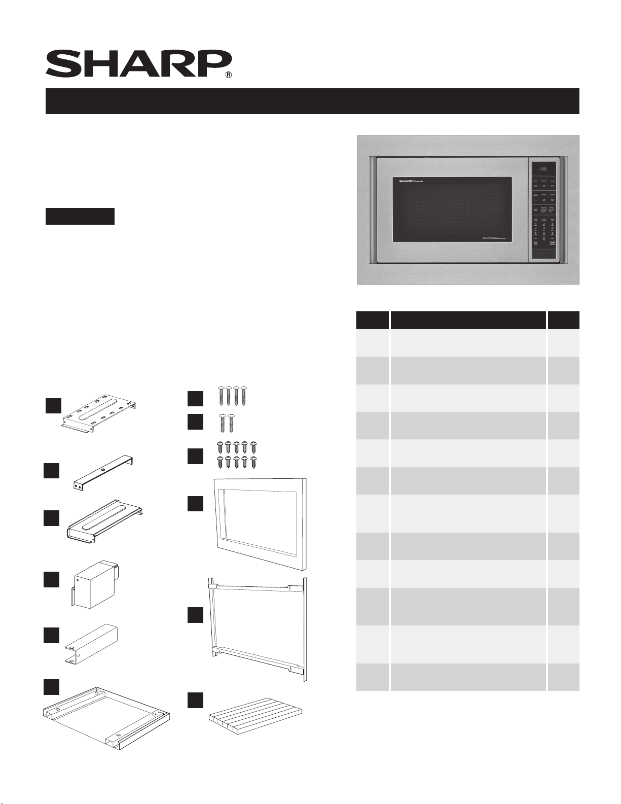
For Sharp Built-in Kit Models RK-94S27 or RK-94S30
THIS KIT IS UL APPROVED TO ALLOW CERTAIN MICROWAVE OVENS TO BE INSTALLED
ABOVE ANY ELECTRIC WALL OVEN. PLEASE SEE THE OPERATION MANUAL
REGARDING APPROVED BUILT-IN APPLICATIONS.
IMPORTANT:
This Built-in Kit is designed for and approved only for those Sharp
Microwave Ovens specifying Built-In Kit RK-94S27 or RK-94S30.
Refer to operation manual for approved models or www.sharpusa.
com\trimkits
PLEASE READ THESE INSTRUCTIONS
THOROUGHLY BEFORE
BEGINNING INSTALLATION!
• Always DISCONNECT THE PLUG of the microwave oven from the
electrical outlet before installing the Built-in Kit. Remove the Carousel turntable from the oven cavity.
• Because the kit includes metal parts, due caution should be used
in handling and installation to avoid the possibility of injury.
A
DUCT (A)-1
G
H
I
B
DUCT (A)-2
J
C
DUCT (A)-3
D
DUCT (B)
K
ITEM PART NAME QTY
A DUCT (A)-1
PDUC-0259WRW0
B DUCT (A)-2
PDUC-B127MRP0
C DUCT (A)-3
PDUC-A734WRW0
D DUCT (B)
PDUC-0260WRW0
E DUCT (C)
PD UC-A 274WRW0
F BOTTOM DUCT ASSEMBLY
FDUC-B099MRK1A
G M3.9-16MM PAN HEAD TAPPING
SCREW, ZINC
XOPS740P16000
H WOOD SCREW
XTSS740P20000
I CABINET SCREW/ CLEAR
XOTS740P12000
J FRONT FRAME
RK-94S27: FDECAB229MRK0
RK-94S30: FDECAB227MRK0
1
1
1
1
1
1
4
2
10
1
E
DUCT (C)
F
L
K BACK FRAME
RK-94S27: FDECAB230MRK0
RK-94S30: FDECAB226MRK0
L CUSHION SHEET
PCUSGB059MRP0
Check list for parts when unpacking. Note J. Front
1
1
Frame and K. Back Frame are shipped attached.
Snap apart before installation.
1
E
Page 2
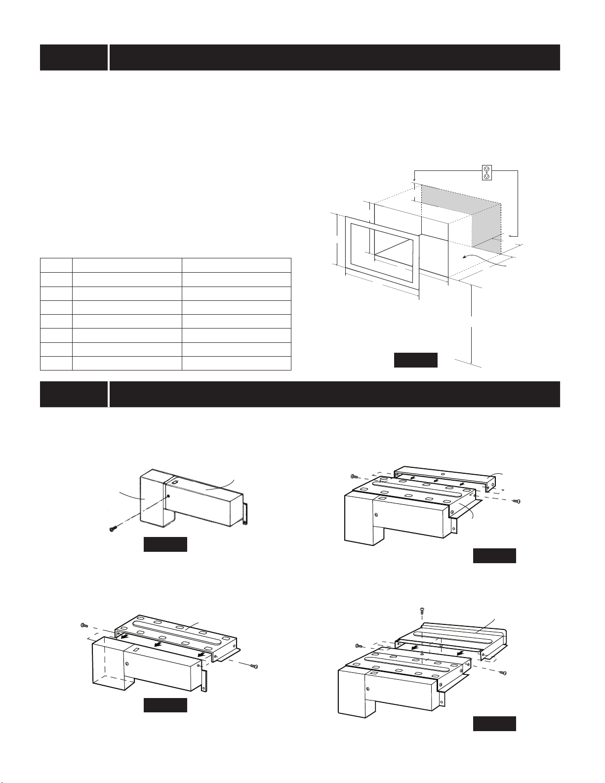
STEP 1 CABINET OR WALL OPENING
Provide an opening in the wall or cabinet as indicated in
Figure 1. The depth should be a minimum of 20-1/8". If the
Depth (E) dimension is greater than 21", the outlet location
may be in any area on the rear wall. The oor of the opening
should be constructed of plywood strong enough to support
the weight of the oven (approximately 100 lbs.) and should
be level for proper operation of the oven.
NOTE: While the proper function of the oven does not
require that the opening be enclosed (with sides, ceiling
and rear partition), this may be required by local code, and
it is suggested that the local code be checked for any such
requirement.
The opening in the wall or cabinet must be within the
following dimensions, centered horizontal to the cabinet.
RK-94S27 RK-94S30
A 20" 20"
B 26 -7/8" 29 -7/8"
C 18-1/2" 18-1/2"
D 25 -1/4" 25-1/4"
E Min. 20-1/8" Min. 20-1/8"
F 5" 5"
G 10" 10"
Outlet should NOT be in the shaded area as indicated on
Figure 1.
NOTE
• If the dimension of DEPTH (E) is more than 21", the outlet
location may be any area on the rear wall.
F
C
A
D
B
G
FLOOR
E
NOTE: Floor of opening
should be 90˚ to front
34-1/2” MIN.
cabinet frame.
Figure 1
FLOOR
STEP 2 EXHAUST DUCT ASSEMBLY
A. Insert the edge of DUCT (B) into the hold lip of DUCT (C).
Secure together by using a SCREW (I) provided in the kit.
See Figure 2.
DUCT (B)
SCREW (I)
Figure 2
B. Position DUCT (A)-1 on the top of the oven inserting
edge of DUCT (BC) assembly into hole lip of DUCT (A)-1.
Tighten two SCREWS (I), securing DUCT (A)-1 to DUCT
(BC) assembly. See Figure 3.
SCREW (I)
DUCT (BC)
DUCT (C)
DUCT (A)-1
SCREW (I)
C. Position DUCT (A)-2 on the top of the oven and insert it
into the hold lip of DUCT (A)-1. Secure DUCT (A)-2 to DUCT
(A)-1 using two SCREWS (I) provided. See Figure 4.
SCREW (I)
DUCT (A)-1
DUCT (A)-2
SCREW (I)
Figure 4
D. Position DUCT (A)-3 on top of the oven and insert it into
DUCT (A)-2. Secure DUCT (A)-3 using three SCREWS (I)
provided. See Figure 5.
SCREW (I)
SCREW (I)
DUCT (A)-3
SCREW (I)
DUCT (A)-2
Figure 3
Figure 5
E
2
Page 3
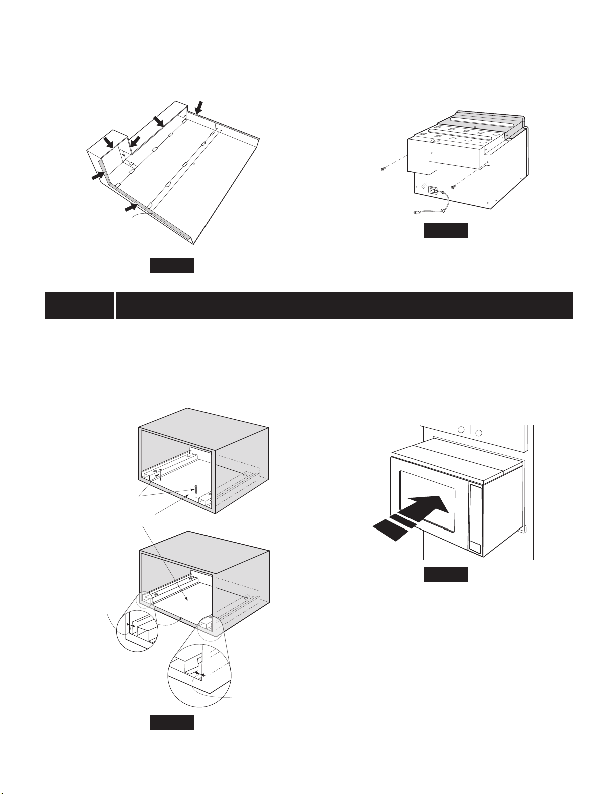
E. Carefully turn over exhaust assembly. Remove adhesive
backing from CUSHION L. The cushion should be applied
to the anges of the duct assembly as indicated by
arrows. See Figure 5A.
F. Remove SCREW from the upper right and left corners at
the rear of the oven. Place duct assembly on the top of
the unit as shown and secure the duct assembly to the
oven using the two screws just removed from the oven.
See Figure 5B.
SCREW
SCREW
CUSHION L
Figure 5A
STEP 3 SURFACE INSTALLATION
A. BOTTOM DUCT ASSEMBLY: Place the Bottom duct in the
center of the opening so that gap "A" is equal to gap "B".
When the Bottom Duct assembly is positioned properly,
the front edge of the duct will be ush with the front of the
cabinet. Secure with 2 SCREWS (H) See Figure 6.
SCREW (H)
Figure 5B
B. CABINET INSTALLATION: Place the oven adjacent to
the wall or cabinet opening. Plug the power cord into the
electrical outlet. Carefully guide the assembled oven into
the prepared opening. Slide the oven on the Bottom Duct
assembly. See Figure 7.
BOTTOM DUCT ASSEMBLY
GA P "A"
NOTE:
CENTER BOTTOM
DUCT ASSEMBLY IN
THE OPENING
DETAIL A
Figure 6
GAP "B"
Figure 7
3
E
Page 4

C. CABINET INSTALLATION: Avoid pinching the cord
between the oven and the wall. Adjust the position of the
oven so that the feet of the oven are tted into the holes
of the Bottom Duct Assembly. See Figure 8.
FOOT
E. FRONT FRAME INSTALLATION: Place the FRONT FRAME
onto the BACK FRAME and align ball studs and receivers.
Secure the FRONT FRAME to the BACK FRAME by rmly
pushing the front frame onto the back frame engaging the
four (4) snap attachments. See Figure 10.
BOTTOM
DUCT
ASSEM BLY
DUCT RECESS
Figure 8
D. BACK FRAME INSTALLATION: Position back frame equal
space top to bottom, side to side. Mark for 4 holes, center
punch and pre-drill with 1/16" drill bit. Secure frame with 4
SCREWS (G). See Figure 9.
MOUNTING HOLES
EQUAL GAP
SIDE TO SIDE
EQUAL GAP TOP, BOTTOM
MOUNTING HOLES
SNAP
ATTACHMENT
Figure 10
MOUNTING HOLES
MOUNTING HOLES
Figure 9
SHARP ELECTRONICS CORPORATION
1 Sharp Plaza Suite 1, Mahwah, New Jersey 07495-1123, U.S.A.
SHARP ELECTRONICS OF CANADA LTD.
335 Britannia Road East Mississauga, Ontario L4Z 1W9, Canada
E
4
For any other assistance or information about this kit,
in USA please call Sharp’s Customer Assistance Center at
1-800-BE-SHARP (1-800-237-4277)
In Canada, call 905-568-7140
Page 5

INSTRUCTIONS D'INSTALLATION
Pour les ensembles de modèles Sharp à
encastrer RK-94S27 ou RK-94S30
CETTE TROUSSE EST CONFORME AUX NORMES UL EN CE QUI CONCERNE LA POSSIBILITÉ
D'INSTALLER CERTAINS FOURS À MICRO-ONDES AU-DESSUS DE TOUT FOUR ENCASTRÉ
ÉLECTRIQUE. VEUILLEZ CONSULTER LE MODE D'EMPLOI CONCERNANT LES TYPES
D'INSTALLATIONS ENCASTRÉES APPROUVÉES.
IMPORTANT :
Cette trousse d'encastrement est conçue pour et a été approuvée
uniquement pour les fours à micro-ondes Sharp exigeant les trousses
d'encastrement RK-94S27 ou RK-94S30. Veuillez consulter le mode
d'emploi pour connaître les modèles approuvés ou visiter le www.
sharpusa.com\trimkits.
VEUILLEZ LIRE ATTENTIVEMENT CES INSTRUCTIONS AVANT
DE COMMENCER L'INSTALLATION!
• Veuillez toujours DÉBRANCHER LA FICHE du four à micro-ondes
de la prise électrique avant d'installer la trousse d'encastrement.
Retirer le plateau tournant de la cavité du four.
• La trousse comprend des parties métalliques, il faut donc faire
preuve de prudence lors de la manipulation et de l'installation an
d'éviter d'éventuelles blessures.
A
DUCT (A)-1
G
H
I
B
DUCT (A)-2
J
C
DUCT (A)-3
ARTICLE NOMS DES PIÈCES QTÉ
A CONDUIT (A)-1
PDUC-0259WRW0
B CONDUIT (A)-2
PDUC-B127MRP0
C CONDUIT (A)-3
PDUC-A734WRW0
D CONDUIT (B)
PDUC-0260WRW0
E CONDUIT (C)
PD UC-A 274WRW0
F ASSEMBLAGE DU CONDUIT
INFÉRIEUR
FDUC-B099MRK1A
G VIS À TÔLE À TÊTE
CYLINDRIQUE
LARGE M3.9 - 16 MM, ZINC
XOPS740P16000
H VIS À BOIS
XTSS740P20000
1
1
1
1
1
1
4
2
D
E
F
DUCT (B)
DUCT (C)
K
I VIS POUR ARMOIRE/
TRANSPARENT
XOTS740P12000
J CADRE DE FAÇADE
RK-94S27: FDECAB229MRK0
RK-94S30: FDECAB227MRK0
K CADRE ARRIÈRE
RK-94S27: FDECAB230MRK0
RK-94S30: FDECAB226MRK0
L FICHE DE COUSSIN
L
1
Veuillez vérier la liste des pièces lors du déballage.
Remarque : Les pièces J. Cadre de Façade et K.
Cadre arrière sont expédiées attachées. Veuillez les
détacher avant l'installation.
PCUSGB059MRP0
10
1
1
1
F
Page 6

ÉTAPE 1 OUVERTURE DE L'ARMOIRE OU DU MUR
Faire une ouverture dans le mur ou l'armoire comme illustré
à la Figure 1. La profondeur doit être d'une longueur minimum
de 51,1 cm (20 1/8 po). Si la profondeur (E) dépasse 53,3 cm
(21 po), l'emplacement de la prise peut être situé n'importe où
sur le mur arrière. Le plancher de l'ouverture doit être construit
dans un contreplaqué assez fort pour supporter le poids du
four et sa propre charge (environ 45,36 kg [100 lb]) et doit être
situé à un niveau convenable pour l'utilisation du four.
REMARQUE : Bien que le bon fonctionnement du four
n'exige pas que l'ouverture soit close (avec cloisons latérales,
arrière et plafond), le code local pourrait l'exiger; il est donc
suggéré de vérier ce point.
L'ouverture du mur ou de l'armoire doit respecter les
dimensions suivantes et être centrée horizontalement dans
l'armoire.
RK-94S27 RK-94S30
A 50,8 cm (20 po) 50,8 cm (20 po)
B 68,3 cm (26 7/8 po) 75,9 cm (29 7/8 po)
C 47 cm (18 1/2 po) 47 cm (18 1/2 po)
D 64,1 cm (25 1/4 po) 64,1 cm (25 1/4 po)
E Min. 51,1 cm (20 1/8 po) Min. 51,1 cm (20 1/8 po)
F 12,7 cm (5 po) 12,7 cm (5 po)
G 25,4 cm (10 po) 25,4 cm (10 po)
La prise NE doit PAS se trouver dans l'aire ombrée comme
illustré à la schéma 1.
REMARQUE
• Si la profondeur (E) dépasse 53,3 cm (21 po), l'emplacement
de la prise peut être situé n'importe où sur le mur arrière.
F
C
A
D
B
E
G
FLOOR
PLANCHER
REMARQUE : Le
plancher de l'ouverture
doit former un angle
MIN. 87,6 CM
34-1/2” MIN.
(34 1/2 PO)
90o avec le cadre de
façade de l'armoire.
Schéma 1
PLANCHER
FLOOR
ÉTAPE 2 ENSEMBLE DU CONDUIT D’ÉVACUATION
A. Insérer le bord du CONDUIT (B) dans le joint à lèvre du
CONDUIT (C). Les xer ensemble à l’aide d’une VIS (I)
fournis dans le kit. Voir schéma 2.
CONDUIT
(B)
VIS (1)
Schéma 2
CONDUIT (C)
B. Placer le CONDUIT (A)-1 au dessus du four en insérant
le bord de l’ensemble du CONDUIT (BC) dans la lèvre du
CONDUIT (A)-1. Serrer deux VIS (I) pour xer le CONDUIT
(A)-1 à l’ensemble du CONDUIT (BC). Voir schéma 3.
VIS (I)
CONDUIT (BC)
CONDUIT (A)-1
VIS (I)
C. Placer le CONDUIT (A)-2 au dessus du four et l’insérer
dans le joint à lèvre du CONDUIT (A)-1. Fixer le CONDUIT
(A)-2 au CONDUIT (A)-1 à l’aide de deux VIS (I) fournies.
Voir schéma 4.
VIS (I)
D. Placer le CONDUIT (A)-3 au dessus du four et l’insérer
dans le CONDUIT (A)-2. F ixer le CONDUIT (A)-3 à l’aide
de trois VIS (I) fournies. Voir schéma 5.
VIS (I)
VIS (I)
CONDUIT
(A)-2
VIS (I)
CONDUIT (A)-1
Schéma 4
CONDUIT (A)-3
VIS (I)
Schéma 3
F
2
CONDUIT (A)-2
Schéma 5
Page 7

E. Tourner avec précaution sur l'assemblage d'échappement.
Retirer support adhésif COUSSIN L. Appliquer les coussins
aux brides de l'ensemble conduit comme indiqué par les
èches. Voir schéma 5A.
F. Retirer la VIS des coins supérieurs droit et gauche à
l'arrière du four. Placer l'ensemble conduit au-dessus de
l'appareil comme illustré et xer l'ensemble conduit sur le
four à l'aide des deux vis qui viennent d'être retirées. Voir
schéma 5B.
VIS
VIS
COUSSINS L
Schéma 5A
ÉTAPE 3 INSTALLATION DE LA SURFACE
A. ASSEMBLAGE DU CONDUIT INFÉRIEUR Placer le
conduit inférieur au centre de l'ouverture de sorte que
l'écart « A » soit égal à l'écart « B ». Lorsque l'assemblage
du conduit inférieur est placé correctement, le rebord
avant du conduit sera aligné avec le devant de l'armoire.
Fixer à l'aide des 2 VIS (H). Voir schéma 6.
Schéma 5B
B. INSTALLATION DANS L'ARMOIRE : Placer le four près de
l'ouverture du mur ou de l'armoire. Brancher le cordon
d'alimentation dans la prise électrique. Guider avec
précaution le four assemblé dans l'ouverture préparée.
Faire glisser le four sur l'assemblage du conduit inférieur.
Voir schéma 7.
VIS (H)
ASSEMBLAGE DU CONDUIT INFÉRIEUR
ÉCART « A »
REMARQUE :
CENTRER
L'ASSEMBLAGE DU
CONDUIT INFÉRIEUR
DANS L'OUVERTURE
DÉTAIL A
Schéma 6
ÉCART « B »
Schéma 7
3
F
Page 8

C. INSTALLATION DANS L'ARMOIRE : Éviter de pincer le
cordon entre le four et le mur. Ajuster la position du four
de façon à ce que ses pattes entrent dans les trous de
l'assemblage de conduit inférieur. Voir schéma 8.
PATTE
ASSEMBLAGE
DU CONDUIT
INFÉRIEUR
RENFONCEMENT
DU CONDUIT
Schéma 8
D. INSTALLATION DU CADRE ARRIÈRE : Placer le cadre
arrière à distances égales de haut en bas et de chaque
côté. Tracer l'emplacement de quatre (4) trous au centre à
l'aide d'un poinçon et prépercer à l'aide d'une mèche de
1,45 mm (1/16 po). Fixer le cadre à l'aide de quatre (4) VIS
(G). Voir schéma 9.
E. INSTALLATION DU CADRE DE FAÇADE : Poser le CADRE
DE FAÇADE sur le CADRE ARRIÈRE et aligner les pivots
à rotule avec les agrafes. Fixer le CADRE DE FAÇADE
en le poussant fermement contre le CADRE ARRIÈRE et
en engageant les quatre (4) xations encliquetables. Voir
schéma 10.
FIXATION
ENCLIQUETABLE
TROUS DE FIXATION
MOUNTING HOLES
EQUAL GAP
ÉCART ÉGAL DE
SIDE TO SIDE
CHAQUE CÔTÉ
MOUNTING HOLES
TROUS DE FIXATION
ÉCART ÉGAL DE HAUT EN BAS
EQUAL GAP TOP, BOTTOM
Schéma 9
TROUS DE FIXATION
MOUNTING HOLES
MOUNTING HOLES
TROUS DE FIXATION
Sch éma 10
Pour tout autre type d'aide ou de renseignements
concernant cette trousse, aux États-Unis, veuillez
communiquer au service d'assistance à la clientèle de Sharp
en composant le 1-800-BE-SHARP (1-800-237-4277)
Au Canada, composer le 905-568-7140
SHARP ELECTRONICS CORPORATION
1 Sharp Plaza Suite 1, Mahwah, New Jersey 07495-1123, U.S.A.
SHARP ÉLECTRONIQUE DU CANADA LTÉE,
335, rue Britannia Est, Mississauga, Ontario L4Z 1W9, Canada
F
4
TINSKB224MRR1
 Loading...