

Page 1
SERVICE MANUAL
CODE: 00ZARFX9//A1E
DIGITAL MULTIFUNCTIONAL
SYSTEM OPTION
FACSIMILE EXPANSION KIT
MODEL
AR-FX9
(For North America)
CONTENTS
[1] SPECIFICATIONS . . . . . . . . . . . . . . . . . . . . . . . . . . . . . . . . . . . . . . 1-1
[2] INSTALLATION PROCEDURE. . . . . . . . . . . . . . . . . . . . . . . . . . . . . 2-1
[3] TEST COMMAND. . . . . . . . . . . . . . . . . . . . . . . . . . . . . . . . . . . . . . . 3-1
[4] FAX SOFT SWITCH . . . . . . . . . . . . . . . . . . . . . . . . . . . . . . . . . . . . . 4-1
[5] TROUBLE CODES . . . . . . . . . . . . . . . . . . . . . . . . . . . . . . . . . . . . . . 5-1
[6] CIRCUIT DIAGRAM . . . . . . . . . . . . . . . . . . . . . . . . . . . . . . . . . . . . . 6-1
PARTS GUIDE
Parts marked with “ ” are important for maintaining the safety of the set. Be sure to replace these parts with
specified ones for maintaining the safety and performance of the set.
This document has been published to be used
SHARP CORPORATION
for after sales service only.
The contents are subject to change without notice.
Page 2

[1] SPECIFICATIONS
Large item Middle item Small item Sub item Specifications
Communication
system
Transmission
functions
Electronic
transmission system
Transmission
operation
Auto send function Auto send function to a predetermined telephone
Application send
function
Electronic
transmission time
Compression/
Extraction system
MODEM speed 33600bps - 2400bps (Automatic fall-back)
Mutual communication Super G3/G3
Used line Public switched telephone network (PSTN), Private
Used line number 1 line
Connection form For 1 line of telephone;
ECM Yes
Items which can be
selected and
registered by user
when transmitting
Chain dial Max. 50 digits
Rapid key dial Registration key One-touch key
Number of items Max. 18 items
Number of digits of
destination number
Destination
registration name
Retrieval characters 0 - 3 characters
Communication start
speed
International
communication mode
Transmission method One-touch dial key
Speed dial Number of items 100 items (Reduction number 00 - 99)
Number of digit of
destination number
Destination
registration name
Retrieval characters 0 - 3 characters
Communication start
speed
International
communication mode
Transmission method Speed dial key + (00 - 99) + Start key
Group dial Registration key One-touch dial key
Number of groups
which can be
registered
Destination
registration name
Number of stations
which can be
registered in one
group
Numbers which can be
registered
Retrieval characters 0 - 3 characters
Transmission method Group dial key
Address book send Retrieval target • Speed dial
Retrieval key SEARCH key
Retrieval character 0 - 3 characters
Less than 3 sec (Super G3 mode, 33600bps)
Less than 7 sec (G3 ECM mode, 14400bps)
MH, MR, MMR, JBIG
branch exchange (PBX)
• FAX machine
• External telephone
• Specifying the destination number
• Resolution
• Density
• Transmission start time
• Polling receive
• Cover addition setting
• Send document scan system
number
Max. 40 digits
Max. 20 characters
Max. speed: 33600bps/ High speed: 14400bps/
Middle speed: 9600bps/ Low speed: 4800bps
NO/ Mode 1/ Mode 2/ Mode 3
40 digits
20 characters
Max. speed: 33600bps/ High speed: 14400bps/
Meddle speed: 9600bps/ Low speed: 4800bps
NO/ Mode 1/ Mode 2/ Mode 3
18 items (One-touch dial + Group dial)
20 characters
Max. 100 stations in one group (Max. total items
which can be registered: 150 items)
Destination numbers registered in one-touch dial and
speed dial, 10-key dial
• One-touch dial
• Group dial
AR-FX9 SPECIFICATIONS 1 - 1
Page 3

Large item Middle item Small item Sub item Specifications
Send functions Document scan
function
Send document
information adding
function
Basic send functions Direct send function Yes
Document size Max. document width Inch series: 8.5"
AB series: 210mm
Max. document length 500mm (Only form RSPF/SPF, with user support)
Send document size AB series: A4
Document size
specification
Half-tone reproduction Half-tone 256 gradations
Resolution selection Manual 5 steps
Scan density select
function
Scan resolution select
function
Document table scan
(OC send) function
Sender registration/
send function
Send header function Header display
Page counter function Adding position Top right (The right edge)
Cover adding function Display items • Date and time
Send message adding
function
Index function Yes (Max. 10 kinds in printable area)
Memory send function Send form
Quick online send
function
Auto resend function When busy tone
Long document send
function
Density select Light/Medium/Dark
Selectable image
quality mode
Resolution select Standard: 8dot x 3.85 line/mm
Sender telephone
number
Sender registration
name
content
Adding form P. XXX (Max. 999)
Fixed message NO MESSAGE/CONFIDENTIAL/PLS. DISTRIBUTE/
Number of items of
send reservation
Operation when
memory full
detected
When no response
(CED/ FSK signal are
not detected)
Communication error
Inch series: Letter (8.5 x 11)/Legal (8.5 x 14) (Default:
Letter (8.5 x 11))
Yes
Standard/Fine/Super Fine/Fine + Half-tone/Super
Fine + Half-tone (Default: Standard)
Scan density
Fine: 8dot x 7.7 line/mm
Super Fine: 8dot x 15.4 line/mm
Half-tone: Scan in 256 gradations
Book document scan/send function from the
document table (OC). In one send job, the send
document size is fixed.
20 digits
40 characters
Sender number registered in sender registration/
Sender name/ Send date and time/ page
• Destination name (Max. 20 characters)
• Destination number (Max. 40 digits)
• Sender name (Max. 20 characters)
• Sender number (Max. 20 digits)
• Send quantity (3 digits)
• Send message (When send message adding
function is used)
URGENT/PLS. CALL BACK/IMPORTANT
• Send reservation
• Time specifying send
• Group send
• Serial broadcast
Max. 52 items (excluding redial)
Group send and broadcast are treated as one item.
• Document scan stop
• Memory full display → Job continuation check
• Job continuation: Scanned document data are
sent.
• Job stop: Scanned document data are deleted.
• In either case, document is held in SPF and not
discharged.
Valid when memory mode is ON. Scan of send
document data and send are performed together.
Redial is performed according to the setting of
"Number/interval of redial when busy."
Redial is performed according to the setting of
"Number/ interval of resend in communication error."
Supports up to 500mm. When this length is
exceeded, "PAPER JAM" occurs.
AR-FX9 SPECIFICATIONS 1 - 2
Page 4

Large item Middle item Small item Sub item Specifications
Send functions Application send
function
Incoming
functions
system
Receive
functions
system
Incoming detection
function
Application incoming
function
Receive function Receive standby
Basic receive function Auto receive function The line is switched to FAX by detection of call signal.
Basic receive function Memory receive
Manual send function This function allows to switch to FAX manually when
off-hook with document set.
Time specifying send
function
Group send function A message is sent sequentially to two or more
Serial broadcast
function
Duplex send function Valid only in duplex support models.
Call signal detection
function
Remote select
function by CNG
detection
Distinctive Ring
function
Incoming reject
function
Call sound volume
adjustment function
Alarm sound volume
adjustment function
Key sound volume
setting
Junk FAX protection
function
mode
Manual receive
function
function
Available
communication
Number of set items Max. 5 items
Set range 00:00 - 23:59 (Unit: 1 min)
Day of week 8 kinds (From Monday to Sunday, and no
Broadcast send
destination
Send document size A4/ Letter/ Legal size
Call bell pattern OFF/STANDARD/Pattern 1 - 5
Volume select OFF/LOW/MIDDLE/HIGH
Volume select OFF/LOW/MIDDLE/HIGH
Number of
registrations
Number of calls AUTO: 0 - 9 times (Default: 2 times)
Tel/FAX auto select No
Incoming reject
conditions
Number of calls 0 - 9 times (Default: 0 times)
Substitution receive
function
Forcible memory
receive function
Overtake output
function
Memory send, Polling, serial broadcast, serial send
request
specification)
destinations registered in group dial. (Max. 52
destinations can be registered in one group.)
Max. 100 items
Direct send and scan from OC cannot be made.
Call bell is distinguished from net call signals to judge
incoming.
Receive is started when CNG signal is detected in
standby with external telephone used.
Conforms to the call distinguishing function provided
by the local telephone company.
Incoming is rejected when remaining memory
capacity is less than 7%.
Follows setting on the main unit.
Junk stations are registered to be rejected.
Max. 10 items
• Auto (AUTO)
• Manual (MAN.)
• Answering machine (A.M.)
(receive standby mode)
• During Test Command by serviceman
• Insufficient memory capacity
• During menu
• During memory status display
Receive is manually started.
Receive data are accumulated in memory, and
outputted when output conditions are satisfied.
Countermeasure against print inhibit state.
• No recording paper
• Recording paper jam
• During copy/print job
• During printing by printer
• Cover open
• Paper empty, size error
No
No
AR-FX9 SPECIFICATIONS 1 - 3
Page 5

Large item Middle item Small item Sub item Specifications
Receive
functions
system
Telephone
functions
system
Record table
system
Receive document
output function
Print system Recording paper Recordable size A4/8.5 x 11/8.5 x 14
Transfer function Receive data are transferred to the registered station.
Main unit telephone
function
External telephone
connection function
Report list Report output function Report select • TIMER LIST
Auto reduction/
divided receive
function
Polling receive
function (Send request
function)
Sequential send
request (Polling)
communication
Remote send Scanned document data in memory are sent
Duplex receive Available only in the duplex function support models.
On-hook dial function Yes
Manual redial function Max. memory digit 50 digits
Pause function Yes (Fixed to 2sec)
Pulse/Tone select
function
Select function by
DTMF
Recording table auto
print function
Communication report
list
Auto reduction
function
Divided receive
function
Protection function • Check by sender number
Recording paper
setting
Paper feed Paper feed by tray (Excluding multi manual feed)
Recording paper size
detection
Recording paper
empty detection
Number of registered
transfer destination
Registered telephone
number
Local transfer Countermeasures against an error
Display digits End 20 digits
Number of items Auto print for every 50 items of send/receive total.
Report select • Send report list
Print status select • ALWAYS PRINTS
When the reference line number is in the specified
range.
When the reference line number exceeds the
specified range.
The remote machine must be provided with polling
function. Communication is allowed with an other
company machine.
Polling is made to two or more specified destinations.
Number of items of destination registration: Max. 100
items
automatically by send request from the remote
machine.
• Check by allow number
AUTO/TRAY 1/TRAY 2 (When the option installed)
(In AUTO, TRAY1 has priority.) (Default: AUTO)
The recording paper length is detected. If the size
differs, a paper size error occurs.
Detected by a paper pickup error.
1 item
40 digits
• Paper jam
• No toner cartridge
• No toner
• During toner supply
• CRU life
• No recording paper
Yes
Select number (1 digit) + [**] (0 - 9)
• ACTIVITY REPORT
• TELEPHONE# LIST
• GROUP LIST
• PASSCODE LIST
• JUNK FAX# LIST
• USER PROGRAM LIST
• Receive report list
• Serial broadcast send report list
• Image memory addition
• ERROR ONLY
• NEVER PRINTS
AR-FX9 SPECIFICATIONS 1 - 4
Page 6

Large item Middle item Small item Sub item Specifications
Memory
functions
system
Memory outline Memory capacity Standard memory 2MB
Option No
Document quantity to
A4 standard documents 120 pages
be stored
Data storage area/
backup when service
interruption (Recorded
data, receive data)
Image data Flash memory (Data are retained when the power is
turned off or when the battery is exhausted.)
Data other than image SRAM (Data are retained when the power is turned
off, but deleted when the battery is exhausted with
the power OFF.)
Treatment when
memory full
Quick online Memory full on the first
page
Memory full on the
second or later page
Memory send Memory full on the first
Send cancel without call-out
The line is shut-off after sending the last page of
scanned data.
Send cancel
page
Memory full on the
second or later page
Send/Cancel is selected depending on the select
menu display.
Send: The line is shut off after sending the scanned
data.
Cancel: Cancel even scanned data.
Memory status check
function
Memory content check
function
Yes (The remaining memory capacity (%) is
displayed on the LCD.)
Not-sent job is displayed on the LCD. (Cancel is
possible.)
Document jam Error LED, LCD message are displayed.
Service
functions
system
Test command
function
Counter function Communication
counter
Send/receive of specified signals, commands, and
image data are performed without a remote machine.
• Number of send pages
• Number of receive pages
• Number of output pages
• Send time
• Receive time
Others Environmental
functions
Auto clear Conforms to the main unit setting. When the
operation is left for 1 min or more, the display returns
to the main menu.
Auto shut -off Conforms to the main unit setting.
Date and time setting
Month/ Day/ Year/ Day of week/ O'clock/ minute
function
Image priority function STANDARD/FINE/SUPER FINE
BEEP LENGTH
3SEC/1SEC/NO BEEP
(Communication end
sound length) setting
Auto summer time
setting
First Sunday of April AM2:00 → 3:00,
Last Sunday of October AM2:00 → 1:00
(Default: OFF)
Multi language
Conforms to the main unit setting.
function
AR-FX9 SPECIFICATIONS 1 - 5
Page 7
[2] INSTALLATION PROCEDURE
<Before installation>
For improvement of workability, some description in this manual as
well as components and accessories may change without prior notice.
In this case, refer to the service manual.
Turn off the main switch of the copier and then remove the power plug
of the copier from the outlet.
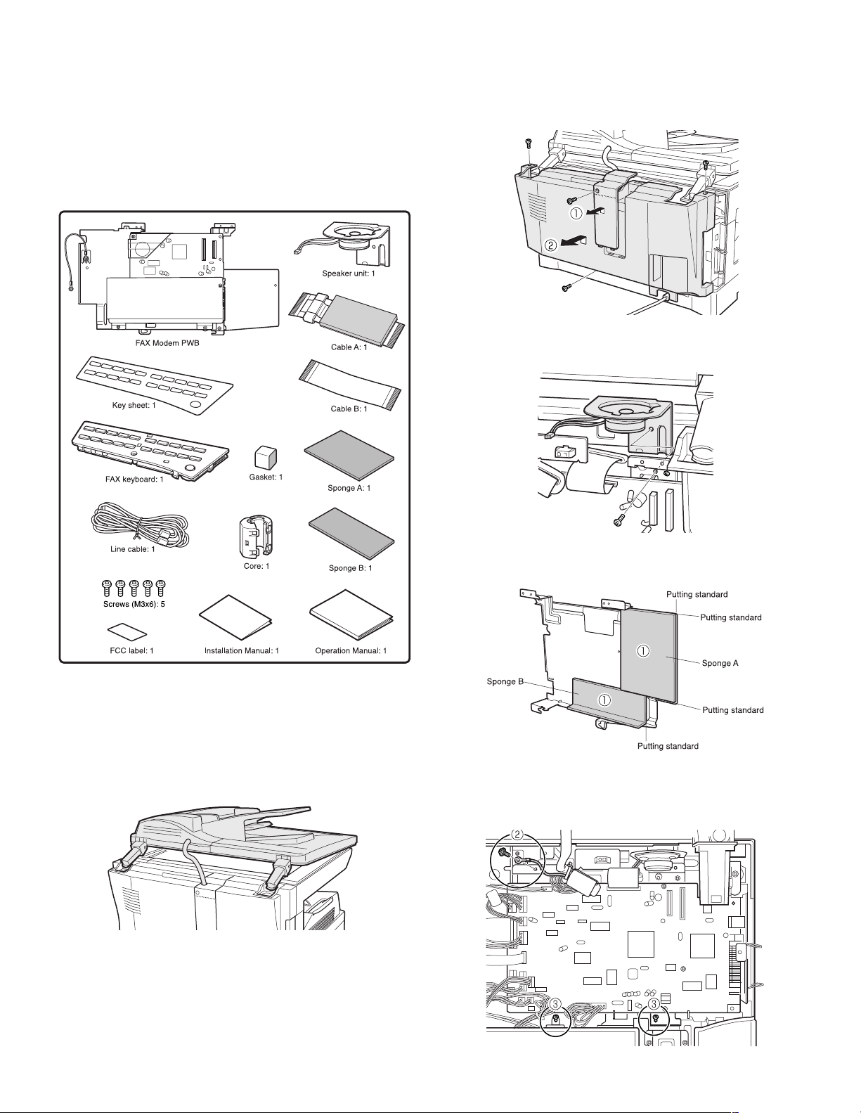
1. Parts included
(2) Remove the rear cabinet.
1) Unscrew the screw and remove the rear cabinet shielding plate.
(Save the screw.)
2) Unscrew three screws and remove the rear cabinet. (Save the
screws.)
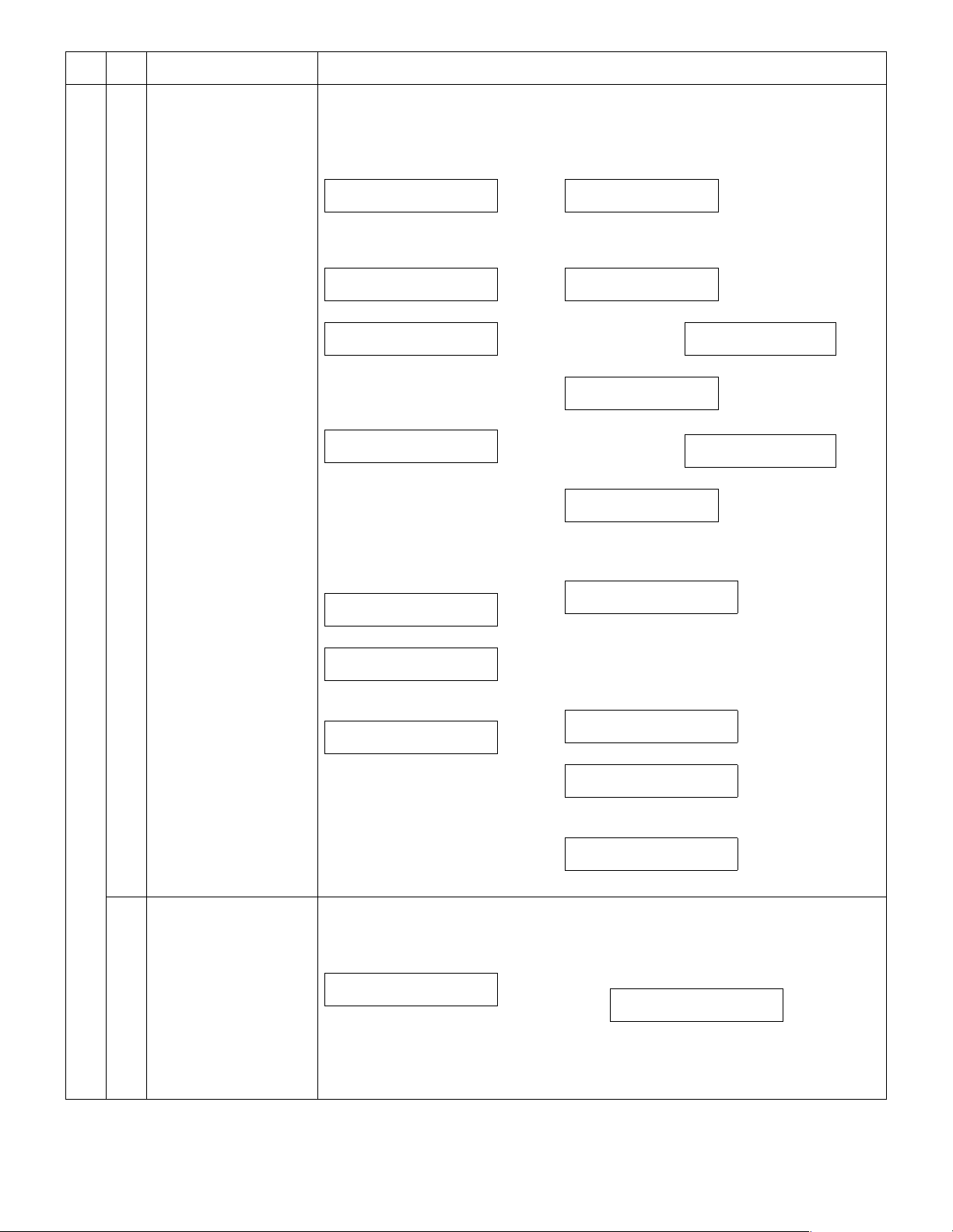
(3) Attach the speaker unit.
Attach the speaker unit using a supplied screw as shown below.
Remove all pieces of fixing tape and fixing materials from the
finisher.
2. Installation procedure
(1) Detach the SPF.
Detach the SPF from the copier and softly place it on top of the original
table as shown below.
(4) Attach the FAX modem PWB.
1) Attach sponge A and sponge B on the back of FAX PWB.
2) Unscrew the screw holding the ground terminal of the copier.
(Save the screw.)
3) Insert two supplied screws and tighten them loosely as shown
below.
AR-FX9 INSTALLATION PROCEDURE 2 - 1
Page 8
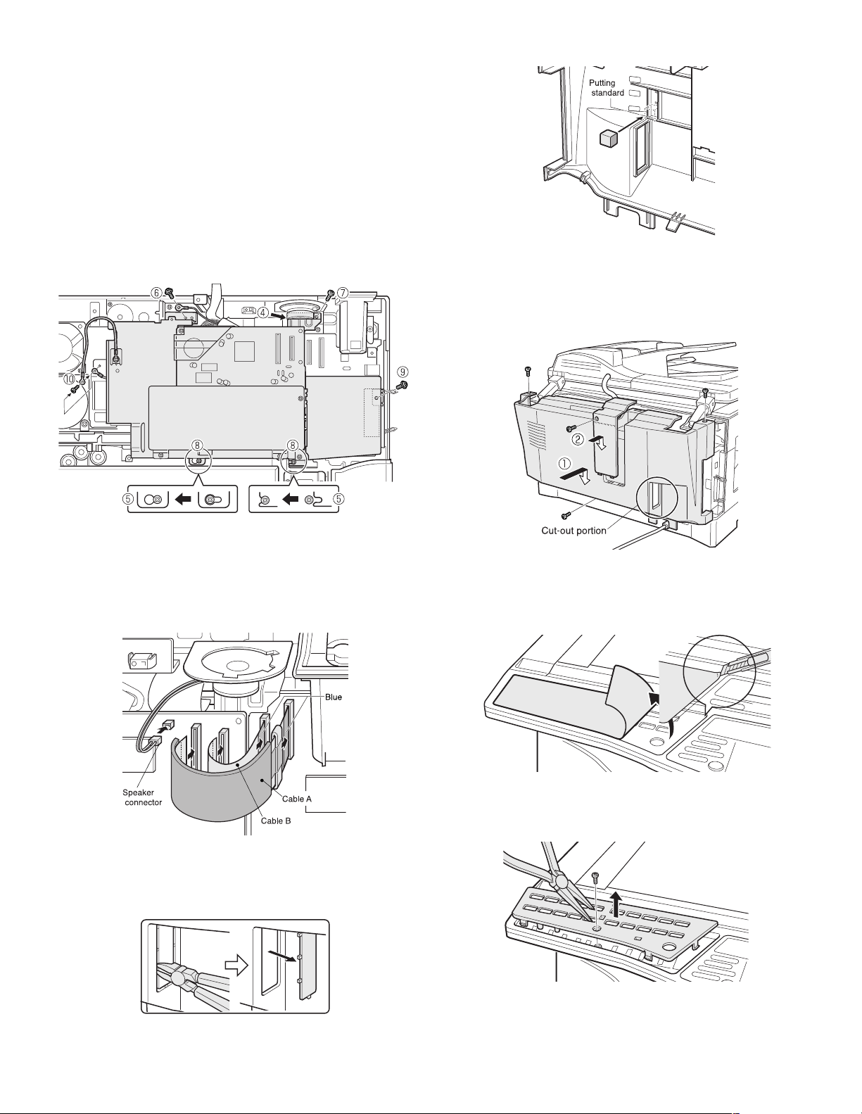
4) Align the top frame portion of the FAX modem PWB with the screw
hole at the back of the speaker unit.
5) Place the holes of the bottom portion of the FAX modem PWB onto
the loosely tightened screws.
Slide the PWB to left to secure as shown below.
6) Secure the ground terminal and the FAX modem PWB onto the
copier using the screw removed earlier in Step 2).
7) Secure the FAX modem PWB onto the copier using a supplied
screw.
8) Tighten three loosely tightened screws completely.
9) Secure FAX modem PWB aluminum sheet onto the copier using a
supplied screws.
10) Unscrew the screw securing the ground terminal of the motor
plate, and secure it again together with the ground terminal of the
FAX PWB as shown.
2) Attach the gasket as shown.
(7) Reattach the rear cabinet.
1) Reattach the rear cabinet and secure it using three screws.
2) Reattach the rear cabinet shielding plate and secure it using one
screw removed earlier.
Reattach the SPF detached in Step (1).
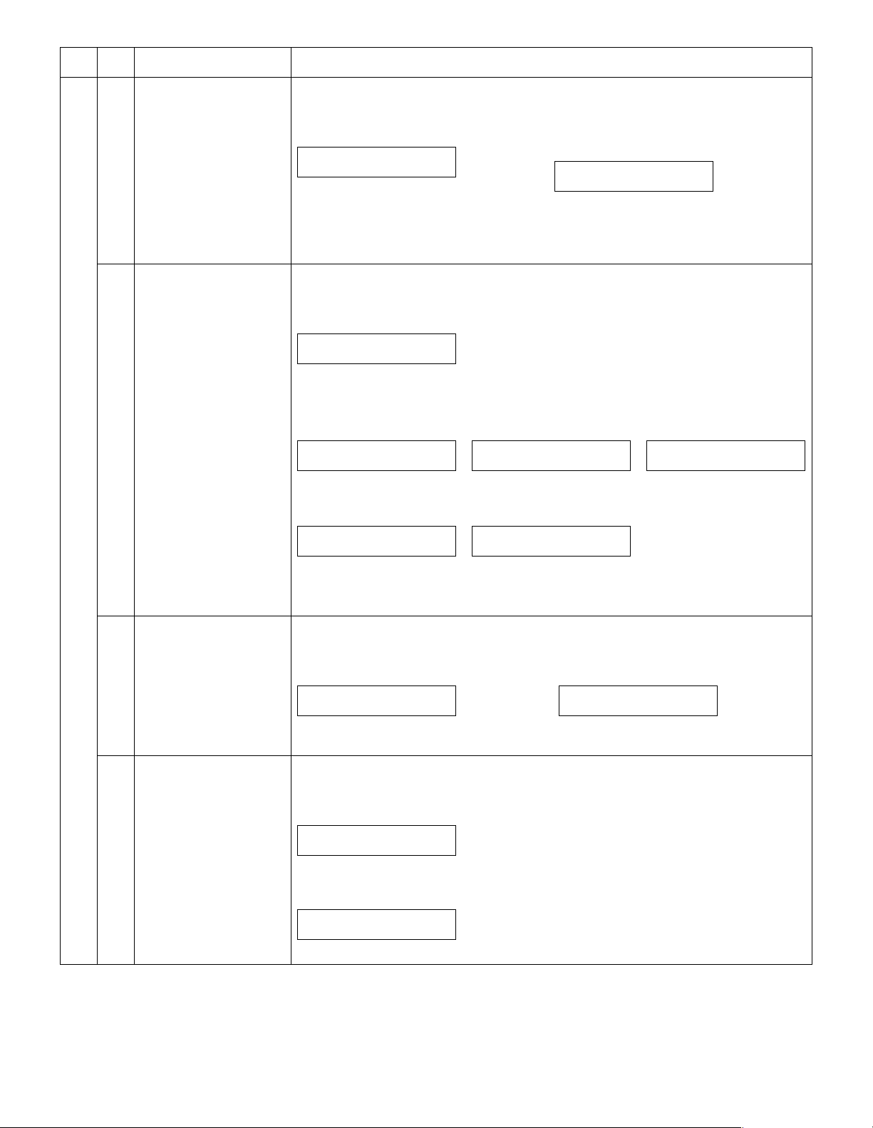
(5) Connect the flat cable A, the flat cable B, and the
speaker connector
Connect the copier and the modem PWB with the flat cable B.
Connect the copier and the modem PWB with the flat cable A.
NOTE: The blue side of the cables must be outer side.
Connect the speaker connector to the modem PWB.
(6) Work the rear cabinet, and attach the gasket.
1) Cut and remove the cut-out portion from the rear cabinet using a
tool such as nippers. (Be careful with the tool’s direction so that the
cut surface is flat.)
(8) Peel off the dummy key sheet.
Open the SPF cover.
Peel the edge of the dummy key sheet using a tool such as a retract-
able knife, and then peel off the entire key sheet.
(9) Remove the dummy keyboard.
Unscrew the screw, and remove the dummy keyboard with a tool like a
pillar as shown below. (Save the screw.)
AR-FX9 INSTALLATION PROCEDURE 2 - 2
Page 9
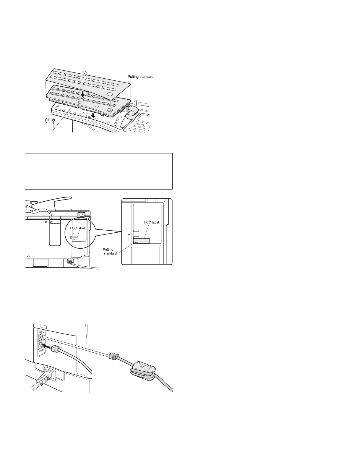
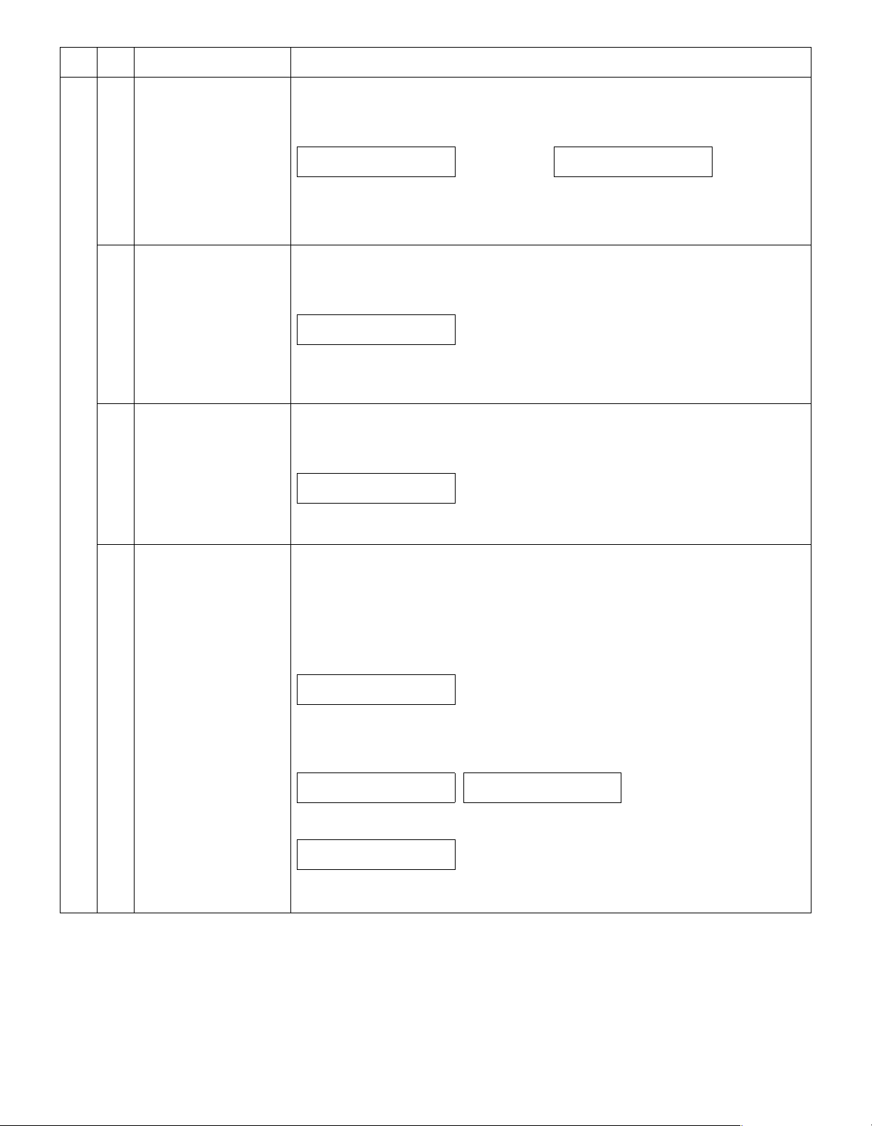
(10) Attach the FAX keyboard.
1) Connect the copier flat cable to the FAX keyboard. Note that the
cable should be folded as shown below and placed under the keyboard.
2) Place the FAX keyboard and secure it using the screw removed
earlier.
3) Affix the key sheet to the FAX keyboard.
(11) Paste the label on the rear cabinet of the copier.
Paste the FCC label on the position shown in the illustration.
In order to manifest the compliance with FCC Part 68 and IC CS-03,
it is required to provide the machine with the FCC Registration Number (USA), Ringer Equivalence (USA) and Ringer Equivalence (Canada).
After installing the FAX expansion kit in the machine, please put the
registration label, packed with the kit, on the prescribed location.
Insert the power plug of the copier to the outlet and turn on the
main switch of the copier. Then, carry out the following
procedure.
(12) Connect the FAX modem PWB line cable.
Connect the line cable to the FAX modem PWB.
To set up a telephone, wrap the line cable twice around the core, and
connect it to the FAX modem PWB as shown.
AR-FX9 INSTALLATION PROCEDURE 2 - 3
Page 10

[3] TEST COMMAND
1. Entering the test command mode
To enter the serviceman test command mode, press the keys as
follows:
[#] key
→ [*] key → [C] key → [*] key
To cancel the test command mode, press the [CA] key.
2. Key rule
[10KEY]: Entry of MAIN CODE/SUB CODE
←/→]: Selection of MAIN CODE/SUB CODE
[
[ENTER/START]: Settlement
[C]: (Interrupting operation check) Returns to the upper hierarchy.
[CA]: Exits from the test command mode.
Selection of an item
Setup of an adjustment value in case of test commands for adjustment
Selection of an item
<In case of test commands for print>
[ENTER]: Settlement (Without print)
[START]: Settlement/Print
In case of test command of operation check, terminates the operations.
For a test command of adjustment, the display returns to the initial display (00-00).
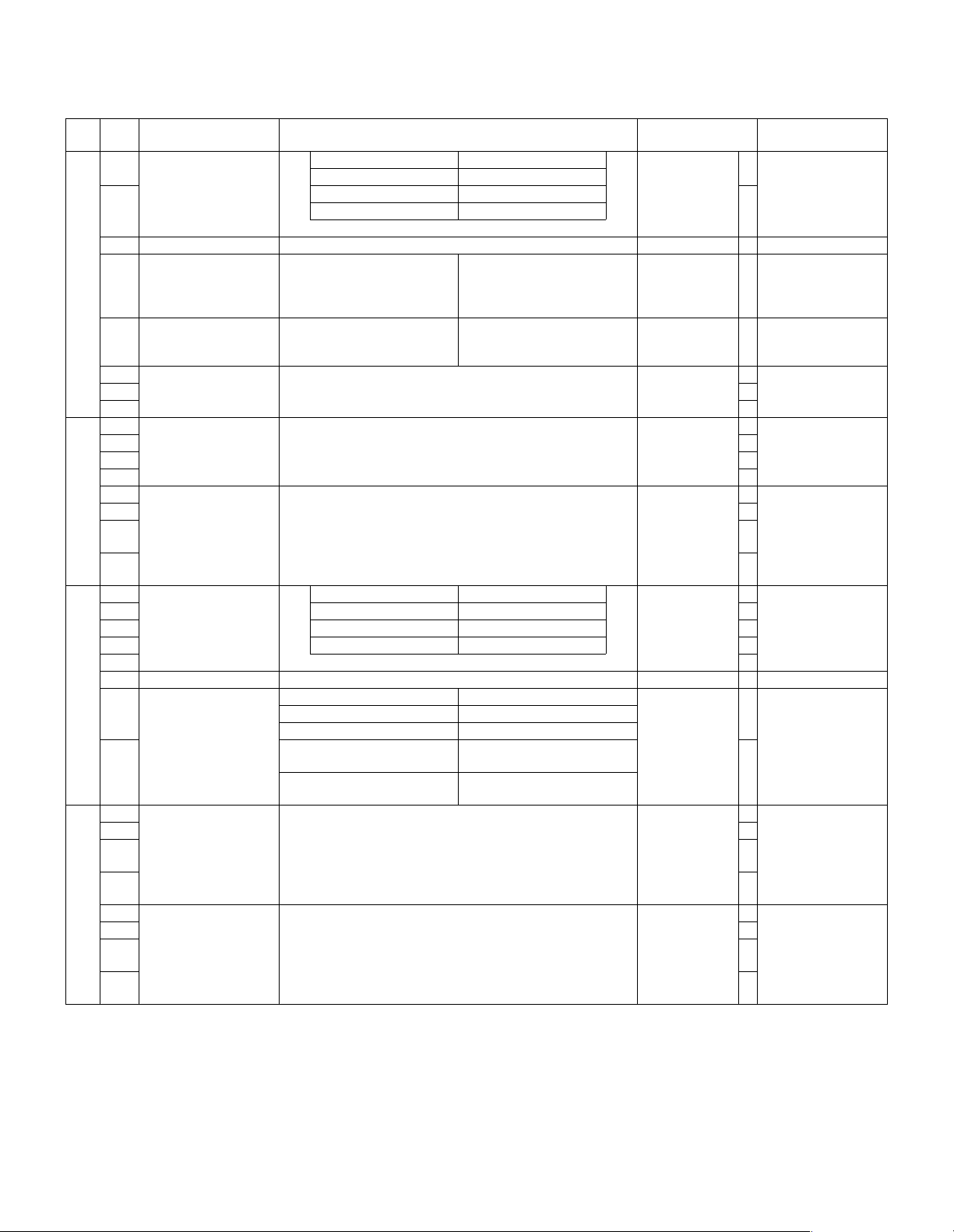
3. List of test commands
Main
Sub
code
code
22 11 FAX-related counter display
24 10 FAX counter clear (FAX CLR.)
46 12 Density adjustment in the FAX mode (Collective
adjustment)
13 FAX mode density adjustment (normal text)
14 FAX mode density adjustment (Fine text)
15 FAX mode density adjustment (Super fine)
39 FAX mode sharpness adjustment
66 01 FAX soft SW setting
02 FAX soft SW initializing (excluding the adjustment
values)
03 FAX PWB memory check
04 Signal send mode (Max. value)
05 Signal send mode (Soft SW set value)
07 Image memory content print
10 Image memory content clear
11 300bps signal send (Max. value)
Contents
Main
Sub
code
code
66 12 300bps signal send (Soft SW set value)
13 Dial test
17 DTMF signal send (Max. value)
18 DTMF signal send (Soft SW set value)
21 FAX information print
24 FAST SRAM clear
30 TEL/LIU status change check
32 Receive data check
33 Signal detection check
34 Communication time measurement
37 Speaker sound volume setting
38 Time setting/check
41 CI signal check
Contents
AR-FX9 TEST COMMAND 3 - 1
Page 11

4. Descriptions of various test commands
Main
Sub
code
code
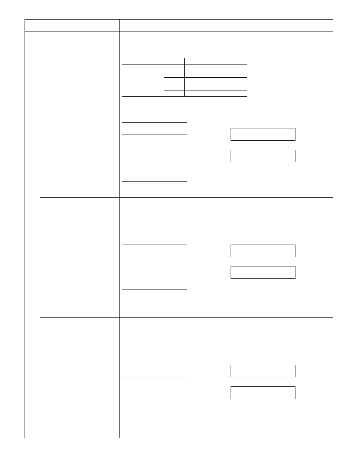
22 11 FAX-related counter display [Function]
24 10 FAX counter clear (FAX
CLR.)
Contents Details of function/operation
The FAX-related counter is displayed.
[Operation]
1) Initial display
SELECT COUNTER
1:PAGE 2:TIME
∗ [CLEAR] key: Returns to the main-sub code
input display.
2) Select 1
SEND PAGE:xxx,xxx
RECV PAGE:xxx,xxx
("xxx,xxx" is the current value.)
∗ [CLEAR] key: Returns to "1) Initial display".
[Function]
When PRINT switch is pressed, the FAX count value is set to 0 and "000,000" is displayed on the
LCD.
[Operation]
1) Initial display
24-10 FAX CLR.
CLEARED 000,000
2) Select 2
TX TIME:xxxx:xx.xx
RX TIME:xxxx:xx.xx
("xxxx: xxx. xx" is the current value.)
∗ [CLEAR] key: Returns to "1) Initial display".
46 12 Density adjustment in the
FAX mode (Collective
adjustment)
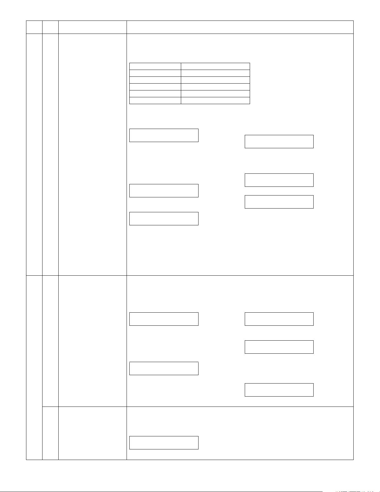
[Function]
When [START] key is pressed, scan is executed with the entered exposure adjustment value and the
data stored on the FAX side is rewritten into the entered value.
All data of the exposure adjustment values are rewritten into the same value.
For the density adjustment table data, refer to TC46-13 (density adjustment (normal text) in the FAX
mode).
[Operation]
1) Initial display
ADJUST EXP. AUTO
XX
("XX" is the exposure adjustment value of normal text stored on the FAX side.)
2) Enter a 2-digit value as the exposure adjustment value.
ADJUST EXP. AUTO
YY
("YY" is the entered exposure adjustment
value.)
3) Scan is started (self print), and the LED of
[START] key is turned off.
ADJUST EXP. AUTO
SCAN YY
4) Print is started (self print).
ADJUST EXP. AUTO
PRINT YY
After completion of printing, returns to “2)” display.
AR-FX9 TEST COMMAND 3 - 2
Page 12
Main
Sub
code
code
46 13 FAX mode density
adjustment (normal text)
14 FAX mode density
adjustment (Fine text)
15 FAX mode density
adjustment (Super fine)
Contents Details of function/operation
[Function]
Scan is started with the exposure adjustment value entered with [START] key, and the stored data of
the selected mode on the FAX side is rewritten into the input value.
Density adjustment value data table
Mode Photo Exposure adjustment value
STD (Normal text) off
Fine (Fine text) on
off
Sfine (Super fine) on
off
When initializing each data: 50
[Operation]
1) Initial display
ADJUST EXP. STD
XX
("XX" is the corresponding exposure adjustment
value of normal text mode stored on the FAX
side.)
2) Enter a 2-digit value as the exposure adjustment value with [10KEY].
ADJUST EXP. STD
YY
("YY" is the entered exposure adjustment
value.)
[Function]
When [START] key is pressed, scan is started with the entered exposure adjustment value and the
data of the selected mode on the FAX side is changed to the entered value.
For the density adjustment value table data, refer to TC46-13 (FAX mode density adjustment (normal
text).)
[Operation]
1) Initial display
ADJUST EXP. FINE
XX
("XX" is the corresponding exposure adjustment
value of the fine text mode stored on the FAX
side.)
2) Enter a 2-digit value as the exposure adjustment value with [10KEY].
ADJUST EXP. FINE
YY
("YY" is the entered exposure adjustment
value.)
[Function]
When [START] key is pressed, scan is started with the entered exposure adjustment value and the
data of the selected mode on the FAX side is changed to the entered value.
For the density adjustment value table data, refer to TC46-13 (FAX mode density adjustment (normal
text).)
[Operation]
1) Initial display
ADJUST EXP. S-FINE
XX
("XX" is the corresponding exposure adjustment
value of the super fine mode stored on the FAX
side.)
2) Enter a 2-digit value as the exposure adjustment value with [10KEY].
ADJUST EXP. S-FINE
YY
("YY" is the entered exposure adjustment
value.)
3) Scan is started (self print), and the LED of
[START] key is turned off.
ADJUST EXP. STD
SCAN YY
4) Print is started (self print).
ADJUST EXP. STD
PRINT YY
After completion of printing, returns to “2)”
display.
3) Scan start (self print)
ADJUST EXP. FINE
SCAN YY
4) Print start (self print)
ADJUST EXP. AUTO
PRINT YY
After completion of printing, returns to “2)”
display.
3) Scan start (self print)
ADJUST EXP. S-FINE
SCAN YY
4) Print start (self print)
ADJUST EXP. S-FINE
PRINT YY
After completion of printing, returns to “2)”
display.
AR-FX9 TEST COMMAND 3 - 3
Page 13
Main
Sub
code
code
46 39 FAX mode sharpness
adjustment
Contents Details of function/operation
[Function]
When [START] key is pressed, scan is started with the entered sharpness adjustment value, and the
data of the selected mode stored on the FAX side is changed to the entered value.
Sharpness adjustment value data table
1: STD
2: FINE
3: S-FINE
4: FINE/PHOTO
5: S-FINE/PHOTO
When initializing each data: 1
[Operation]
1) Initial display
SHARPNESS SETTING
PRESS
2) [←/→] or after 2sec
Every time when [→] key is pressed, the
second line is changed in the sequence of
No. 1 → 2 → 3 → 4 → 5 → 1.
When [←] key is pressed, the sequence is
reversed.
SHARPNESS SET (1-5)
1:STD
3) Select the arrow key 1-5, and the LED of
[START] key is lighted.
SHARPNESS SETTING
ZZZZ(0-2) X
("ZZZZ" is the mode selected among STD,
FINE, S-FINE, FINE/PHOTO, and S-FINE/
PHOTO.)
("X" is the corresponding sharpness adjustment
value of the selected mode stored on the FAX
side.)
[CLEAR] key: Returns to “2)” display.
∗
66 01 FAX soft SW setting [Function]
Use to check the FAX soft SW setting.
Every time when the key is pressed, the bit on the first line is switched 0 and 1.
[Operation]
1) Initial display
ENTER FAX SOFT SW. #
(3 DIGITS) SW.___
[CLEAR] key: Returns to the main-sub code
∗
input display.
2) Enter a 3-digit value of soft SW No. (To
enter the fourth digit, shift to the left.), and
the press [ENTER] key.
No.### xxxxxxxx
CHANGE? 1:YES 2:NO
"xxxxxxxx" is the set content.
Select 2: Returns to the soft SW No. entry dis-
∗
play.
02 FAX soft SW initializing
(excluding the adjustment
values)
[Function]
Use to initializing FAX soft SW.
[Operation]
1) Initial display
INITIALIZED
Mode Sharpness adjustment value
←,→
4) Enter a one-digit value (0-2) as the sharpness adjustment value with [10KEY].
SHARPNESS SETTING
ZZZZ(0-2) Y
("Y" is the entered sharpness adjustment value.)
[CLEAR] key: Returns to “2)” display.
∗
5) Scan start (self print)
SHARPNESS SETTING
SCAN Y
6) Print start (self print)
SHARPNESS SETTING
PRINT Y
After completion of printing, returns to “4)”
display.
3) Select 1
No.### xxxxxxxx
USE # KEY 12345678
4) Change with 1-8 of [10KEY] and the press
[ENTER] key.
No.### xxxxxxxx
STORED? 1:YES 2:NO
"xxxxxxxx" is the set content.
Select 2: Returns to the soft SW No. entry dis-
∗
play.
5) Select 1
STORED
After 2sec, returns to "1) Initial display".
After 2sec, main code and sub code input display.
AR-FX9 TEST COMMAND 3 - 4
Page 14
Main
code
Sub
code
Contents Details of function/operation
66 03 FAX PWB memory check [Function]
Use to check the FAX PWB memory.
[Operation]
1) Initial display
SELECT CHECK MEMORY
PRESS ←, →
2) [←/→] or after 2sec
Every time when [→] key is pressed, the second line is changed in the sequence of No. 1 → 2 →
3 → 1.
When [←] key is pressed, the sequence is reversed.
SELECT MEMORY (1-3)
1:DRAM
[CLEAR] key: Returns to the main-sub code input display.
∗
3) [ENTER] key
CHECKING MEMORY
4) After completion of check
• When the result is OK
MEMORY CHECK RESULT
OK
• In case of sum check error
MEMORY CHECK RESULT
XXXXXXXX SUM NG
[CLEAR] key: Returns to "1) Initial display".
∗
04 Signal send mode (Max.
value)
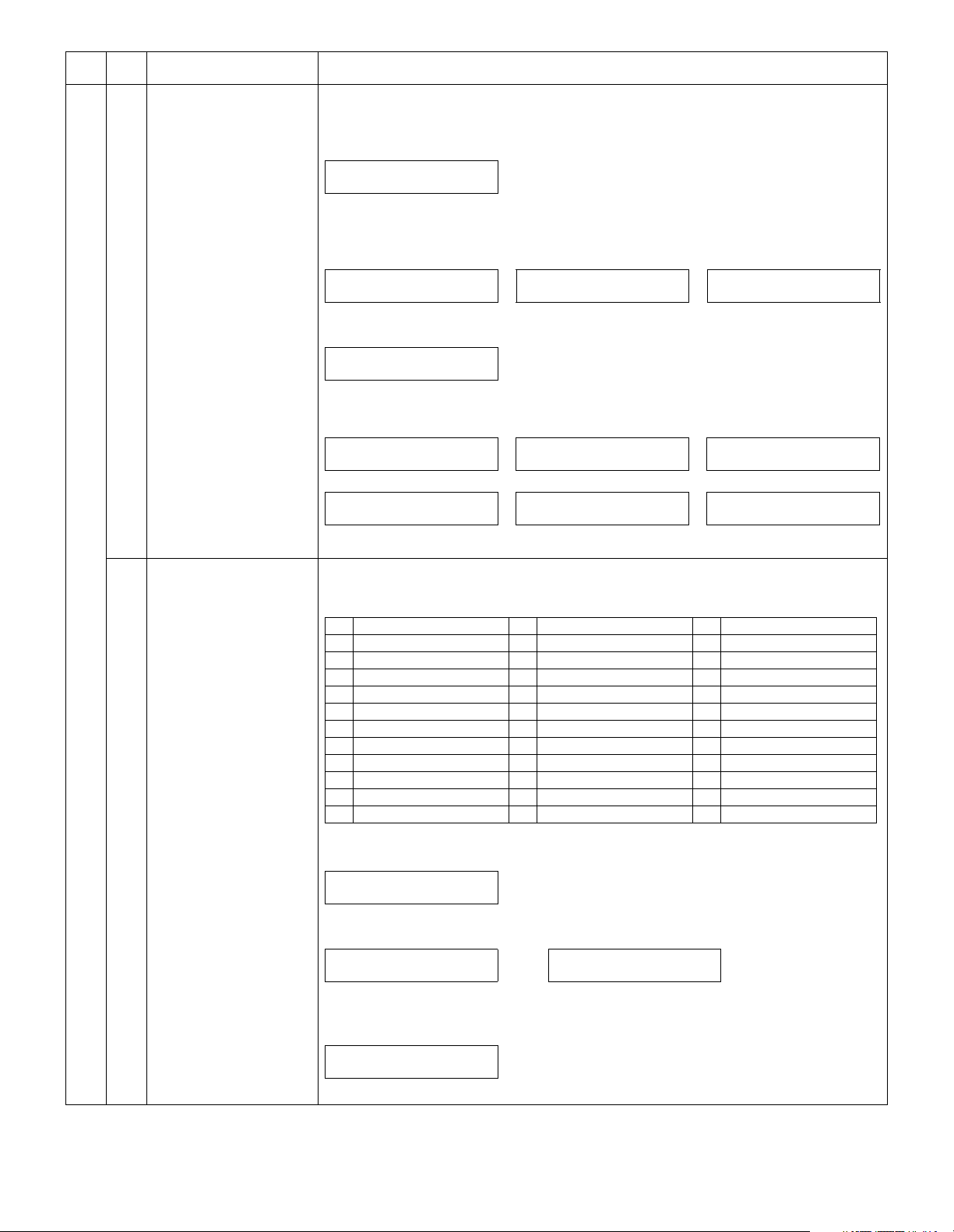
[Function]
Use to set the signal send mode (Max. value).
Facsimile test command design specifications.
1 NO SIGNAL 13 7200bps(V34) 25 2400bps(V27ter)
2 33600bps(V34) 14 4800bps(V34) 26 300bps(FLAG)
3 31200bps(V34) 15 2400bps(V34) 27 2100Hz(CED)
4 28800bps(V34) 16 14400bps(V33) 28 1100Hz(CNG)
5 26400bps(V34) 17 12000bps(V33) 29 300bps(V21)
6 24000bps(V34) 18 14400bps(V17) 30 2100Hz(ANSam)
7 21600bps(V34) 19 12000bps(V17) 31 DUMMY RING
8 19200bps(V34) 20 9600bps(V17) 32 NO VOICE ANSWER
9 16800bps(V34) 21 7200bps(V17) 33 NO RING BACK TONE
10 14400bps(V34) 22 9600bps(V29) 34 LINE OFF HOOK
11 12000bps(V34) 23 7200bps(V29) 35 LINE ON HOOK
12 9600bps(V34) 24 4800bps(V27ter)
[Operation]
1) Initial display
SELECT OUTPUT SIGNAL
(2 DIGITS) No.___
2) 2-digit (1-35) with [10KEY] / [←/→] / 2sec after
Pressing [→] key or [←] key reverses the sequence.
No. (1-35)
1:NO SIGNAL
[CLEAR] key: Returns to the main-sub code input display.
∗
3) [ENTER] key
Send after setting
OUTPUTING SIGNAL MAX
PRESS CLEAR TO STOP
[CLEAR] key: Returns to "1) Initial display".
∗
SELECT MEMORY (1-3)
2:SRAM
• In case of address bus check
error
MEMORY CHECK RESULT
XXXXXXXX A-BUS NG
• In case of data check error
MEMORY CHECK RESULT
XXXXXXXX DATA NG
..... No. (1-35)
35:LINE ON HOOK
SELECT MEMORY (1-3)
3:FLASH
• In case of data bus check
error
MEMORY CHECK RESULT
XXXXXXXX D-BUS NG
• In case of erase check error
MEMORY CHECK RESULT
XXXXXXXX ERASE NG
AR-FX9 TEST COMMAND 3 - 5
Page 15
Main
code
Sub
code
Contents Details of function/operation
66 05 Signal send mode (Soft SW
set value)
07 Image memory content print [Function]
[Function]
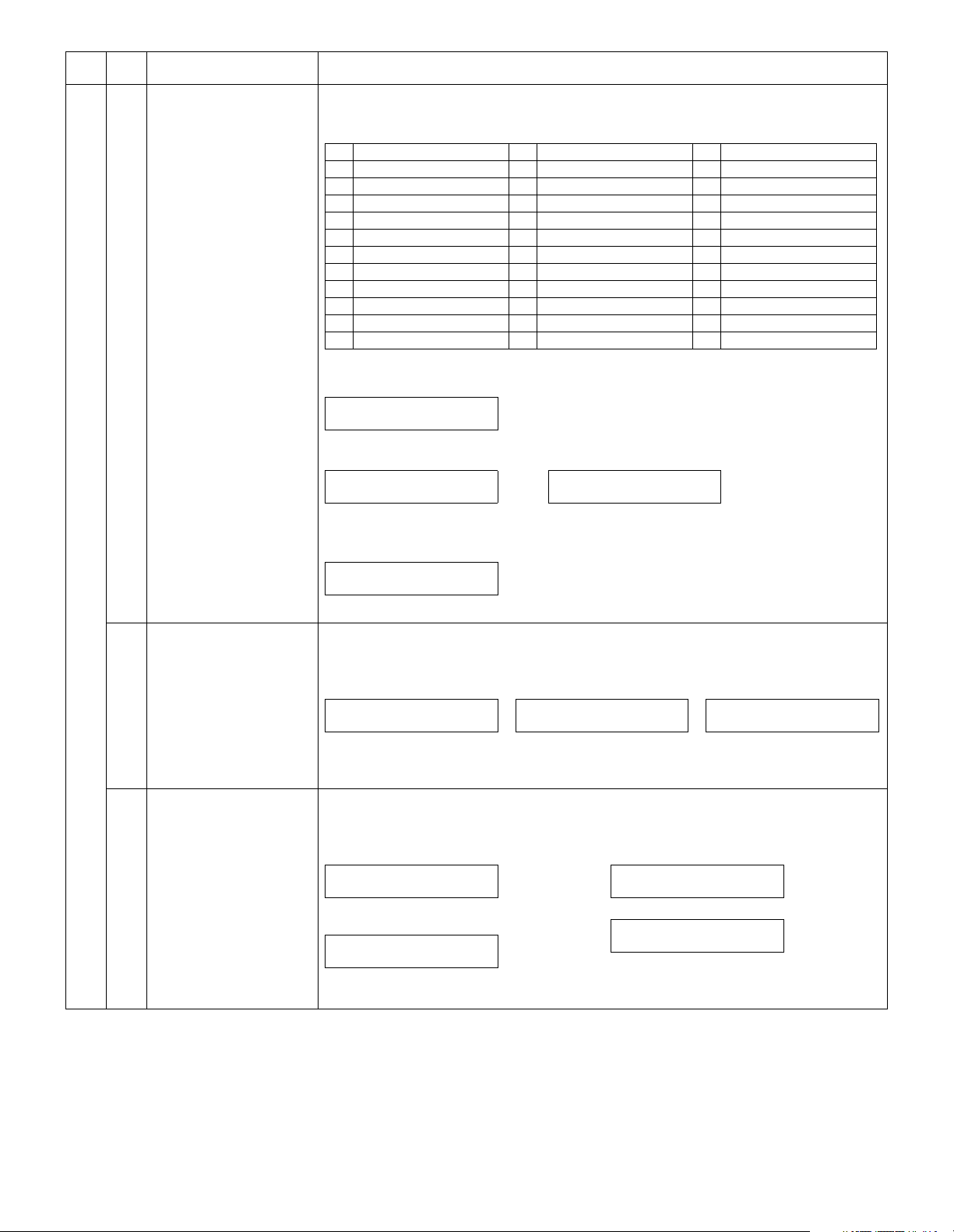
Use to set the signal send mode (Soft SW set value).
Facsimile test command design specifications.
1 NO SIGNAL 13 7200bps(V34) 25 2400bps(V27ter)
2 33600bps(V34) 14 4800bps(V34) 26 300bps(FLAG)
3 31200bps(V34) 15 2400bps(V34) 27 2100Hz(CED)
4 28800bps(V34) 16 14400bps(V33) 28 1100Hz(CNG)
5 26400bps(V34) 17 12000bps(V33) 29 300bps(V21)
6 24000bps(V34) 18 14400bps(V17) 30 2100Hz(ANSam)
7 21600bps(V34) 19 12000bps(V17) 31 DUMMY RING
8 19200bps(V34) 20 9600bps(V17) 32 NO VOICE ANSWER
9 16800bps(V34) 21 7200bps(V17) 33 NO RING BACK TONE
10 14400bps(V34) 22 9600bps(V29) 34 LINE OFF HOOK
11 12000bps(V34) 23 7200bps(V29) 35 LINE ON HOOK
12 9600bps(V34) 24 4800bps(V27ter)
[Operation]
1) Initial display
SELECT OUTPUT SIGNAL
(2 DIGITS) No.___
2) 2-digit (1-35) with [10KEY] / [←/→] / 2sec after
Pressing [→] key or [←] key reverses the sequence.
No. (1-35)
1:NO SIGNAL
[CLEAR] key: Returns to the main-sub code input display.
∗
..... No. (1-35)
35:LINE ON HOOK
3) [ENTER] key
Send after setting
OUTPUTING SIGNAL SSW
PRESS CLEAR TO STOP
[CLEAR] key: Returns to "1) Initial display".
∗
Use to print the image memory content.
[Operation]
• When print is allowed
PRINT STORED
• When there is no print data
• When print is inhibited
NO DATA CAN NOT PRINT
After completion of printing,
main code and sub code input
display.
10 Image memory content clear [Function]
Use to clear the image memory content.
[Operation]
• When there are some print data
CLEAR IMAGE MEMORY
After completion of memory clear, the buzzer
sounds.
CLEARED
PLEASE POWER OFF
Remains unchanged until the power is turned
off.
After 2 sec, FAX control is
terminated.
• When there are no print data
CLEAR IMAGE MEMORY
After completion of memory clear
CLEARED
After 2sec, main code and sub code input display.
After 2 sec, main code and sub
code input display.
AR-FX9 TEST COMMAND 3 - 6
Page 16

Main
code
Sub
code
Contents Details of function/operation
66 11 300bps signal send (Max.
value)
12 300bps signal send (Soft
SW set value)
[Function]
Use to set the 300bps signal send (Max. value).
1: NO SIGNAL
2: 11111
3: 11110
4: 00000
5: 010101
6: 00001
[Operation]
1) Initial display
SELECT SIGNAL
PRESS ←, →
2) [←/→] or after 2sec
Every time when [→] key is pressed, the second line is changed in the sequence of No. 1 → 2 →
3 → 4 → 5 → 6 → 1.
When [←] key is pressed, the sequence is reversed.
SELECT SIGNAL (1-6)
1:NO SIGNAL
[CLEAR] key: Returns to the main-sub code input display.
∗
..... SELECT SIGNAL (1-6)
6:00001
3) [ENTER] key
OUTPUTING SIGNAL MAX
PRESS CLEAR TO STOP
[CLEAR] key: Returns to "1) Initial display".
∗
[Function]
Use to set the 300bps signal send (Soft SW set value).
1: NO SIGNAL
2: 11111
3: 11110
4: 00000
5: 010101
6: 00001
[Operation]
1) Initial display
SELECT SIGNAL
PRESS ←, →
2) [←/→] or after 2sec
Every time when [→] key is pressed, the second line is changed in the sequence of No. 1 → 2 →
3 → 4 → 5 → 6 → 1.
When [←] key is pressed, the sequence is reversed.
SELECT SIGNAL (1-6)
1:NO SIGNAL
[CLEAR] key: Returns to the main-sub code input display.
∗
..... SELECT SIGNAL (1-6)
6:00001
3) [ENTER] key
OUTPUTING SIGNAL SSW
PRESS CLEAR TO STOP
[CLEAR] key: Returns to "1) Initial display".
∗
AR-FX9 TEST COMMAND 3 - 7
Page 17
Main
code
Sub
code
Contents Details of function/operation
66 13 Dial test [Function]
Use to the dial test.
[Operation]
■ Dial test (PULSE)
1) Initial display
SELECT SIGNAL
1:PULSE 2:DTMF
∗ [CLEAR] key: Returns to the main-
sub code input display.
2) Select 1
INPUT MAKE TIME
(0-15) __
3) Enter the make time in 2 digits.
INPUT DIAL #
XXXX
XXXX: Default
∗ After deleting with [CLEAR] key,
input can be made.
4) [ENTER] key
SEND yyPPS xxms
1:YES 2:NO
"yy" is the selected pulse 10 or 20.
"xx" is the input value.
∗ Select 2: Returns to “2)” display.
5) Select 1
Switched to 10/20PPS set with
pulse selection inside.
6) After setting
SENDING yyPPS xxms
7) After completion of sending
TERMINATE ?
1:YES 2:NO
∗ Select 2: Returns to “4)” display.
8) Select 1
TERMINATED
After 2sec, returns to "1) Initial display".
■ Dial test (DTMF)
1) Initial display
SELECT SIGNAL
1:PULSE 2:DTMF
∗ [CLEAR] key: Returns to the main-sub code input dis-
play.
2) Select 2
SELECT HIGH LEVEL
1:DEFAULT 2:SOFT SW.
↓ Select 2
↓
INPUT VALUE
(0-15) __
3) Select 1 ↓
SELECT LOW LEVEL
1:DEFAULT 2:SOFT SW.
↓ Select 2
↓
INPUT VALUE
(0-15) __
4) Select 1 ↓
INPUT DIAL #
XXXX
XXXX: Default
∗ After deleting with [CLEAR] key, input can be made.
4) [ENTER] key
H:xx L:yy
1:YES 2:NO
"xx" indicates HI, and "yy" indicates Low Soft SW.
∗ Select 2: Returns to “4)” display.
5) Select 1
HI/LO is selected with the signal level inside.
6) After setting the signal send level
SENDING DTMF
7) After completion of sending
TERMINATE ?
1:YES 2:NO
∗ Select 2: Returns to “4)” display.
8) Select 1
TERMINATED
17 DTMF signal send (Max.
value)
After 2sec, returns to "1) Initial display".
[Function]
Use to set the DTMF signal send (Max. value).
[Operation]
1) Initial display
INPUT DIAL #
∗ [CLEAR] key: Returns to the main-sub code
input display.
2) [10KEY] input
The content selected with signal send level
selection is set inside.
AR-FX9 TEST COMMAND 3 - 8
3) Communication is started after setting the
signal send level.
SENDING SIGNAL MAX
PRESS CLEAR TO STOP
∗ [CLEAR] key: Returns to "1) Initial display".
Page 18
Main
code
Sub
code
Contents Details of function/operation
66 18 DTMF signal send (Soft SW
set value)
21 FAX information print [Function]
[Function]
Use to set the DTMF signal send (Soft SW set value).
[Operation]
1) Initial display
INPUT DIAL #
3) Communication is started after setting the
signal send level.
SENDING SIGNAL SSW
∗ [CLEAR] key: Returns to the main-sub code
input display.
PRESS CLEAR TO STOP
[CLEAR] key: Returns to "1) Initial display".
∗
2) [10KEY] input
The content selected with signal send level
selection is set inside.
Use to print the FAX information.
[Operation]
1) Initial display
SELECT REPORT (1-3)
PRESS ←, →
2) [←/→] or after 2sec
Every time when [→] key is pressed, the second line is changed in the sequence of 1 → 2 → 3 →
1.
When [←] key is pressed, the sequence is reversed.
SELECT REPORT (1-3)
1:USER SW. LIST
∗ [CLEAR] key: Returns to the main-sub code input display.
3) [ENTER] key
• When print is allowed
PRINT STORED CAN NOT PRINT
After completion of printing,
main code and sub code input
display.
24 FAST SRAM clear [Function]
Use to clear the FAST SRAM.
[Operation]
1) Initial display 2) After completion of clearing
CLEAR FAST SRAM
30 TEL/LIU status change
check
[Function]
Use to check the TEL/LIU status change.
[Operation]
1) Initial display
HS2 :xxx HS1 :xxx
RHS :xxx EXHS:xxx
The display is switched every 2sec.
CHECKING
PRESS CLEAR TO STOP
[CLEAR] key: Returns to the main-sub code input display.
∗
SELECT REPORT (1-3)
2:SOFT SW. LIST
SELECT REPORT (1-3)
3:PROTOCOL
• When print is inhibited
After 2sec, FAX control is
terminated.
CLEARED
After 2sec, main code and sub code input display.
↑
↓
AR-FX9 TEST COMMAND 3 - 9
Page 19
Main
code
Sub
code
Contents Details of function/operation
66 32 Receive data check [Function]
Use to check the receive data.
[Operation]
1) Initial display 2) After completion of reception
RECEIVING
33 Signal detection check [Function]
Use to check the signal detection.
[Operation]
1) Initial display
CHECKING NONE
PRESS CLEAR TO STOP
When a signal is detected, the display is changed from NONE to the following.
CI/CNG/CED/BT/DT/Flag/SDT/DTMF
[CLEAR] key: Returns to the main-sub code input display.
∗
34 Communication time
measurement
[Function]
Use to measurement the communication time.
[Operation]
1) Initial display
COMM. TIME
xx:xx:xx:xxx msec
"xx:xx:xx:xxx" indicates o'clock, minute, second, millisecond.
∗ [CLEAR] key: Returns to the main-sub code input display.
37 Speaker sound volume
setting
[Function]
Use to set the speaker sound volume.
1: NO SOUND
2: LOW
3: MID
4: HIGH
[Operation]
1) Initial display
SELECT SPEEKER VOL.
PRESS ←, →
2) [←/→] or after 2sec
Every time when [→] key is pressed, the second line is changed in the sequence of 1 → 2 → 3 →
4 → 1.
When [←] key is pressed, the sequence is reversed.
SELECT (1-4)
1:NO SOUND
∗ [CLEAR] key: Returns to the main-sub code input display.
3) [ENTER] key
STORED
xxx
xxx: Set content
After 2sec, main code and sub code input display.
SELECT (1-4)
2:LOW
RESULT
xx
"xx" is "OK" or "NG" depending on the check
result.
[CLEAR] key: Returns to the main-sub code
∗
input display.
.....
AR-FX9 TEST COMMAND 3 - 10
Page 20

Main
code
Sub
code
Contents Details of function/operation
66 38 Time setting/check [Function]
Use to check the time setting.
[Operation]
1) Initial display
SELECT TO SET
1:DATE 2:TIME
[CLEAR] key: Returns to the main-sub code
∗
input display.
2) Select 1
xxxx.xx.xx(xxx)
CHANGE? 1:YES 2:NO
"xxxx.xx.xx(xxx)" is the current value. (No revision of display)
3) Select 1
INPUT YEAR
(4 DIGITS)____.__.__
Select 2: Returns to "1) Initial display".
∗
4) Enter the year in 4 digits.
INPUT MONTH
(1-12) 1998.__.__
5) Enter the month in 2 digits.
INPUT DAY
(1-31) 1998.01.__
6) Enter the day in 2 digits.
xxxx.xx.xx(xxx)
STORED? 1:YES 2:NO
"xxxx.xx.xx(xxx) is the entered value.
Select 2: Returns to "1) Initial display".
∗
7) Select 1
STORED
2) Select 2
xx:xx
CHANGE? 1:YES 2:NO
"xx:xx" is the current value.
3) Select 1
INPUT HOUR
(0-24) __:__
Select 2: Returns to "1) Initial display".
∗
4) Enter o'clock in 2 digits.
INPUT MINUTE
(00-59) 01:__
5) Enter minute in 2 digits.
xx:xx
STORED? 1:YES 2:NO
"xx:xx" is the current value.
Select 2: Returns to "1) Initial display".
∗
6) Select 1
STORED
After 2sec, returns to "1) Initial display".
After 2sec, returns to "1) Initial display".
41 CI signal check [Function]
Use to check the CI signal.
When CI signal is detected, OFF → ON.
[Operation]
1) Initial display
CHECKING CI:OFF
PRESS CLEAR TO STOP
[CLEAR] key: Returns to the main-sub code input display.
∗
AR-FX9 TEST COMMAND 3 - 11
Page 21

[4] FAX SOFT SWITCH
1. FAX soft switch setting change quick reference table
Large item Middle item Switch content Key operator Soft SW No. Usage
Dialing Remote machine call
Redial In case of an error Resend interval User program SW 4-1 – 4 When send errors occur frequently
Arrival (Call-in) When CI detection
External
telephone
Communication General Send level None SW 15-4 – 8 When the remote machine cannot receive
Transmission G3/SG3 DIS reception check None SW 6-8 When an error occurs in phase B
Reception G3/SG3 CSI transmission None SW 6-3
Reception print Paper selection Automatic reduction print User program SW 24-8 When reduction print is not made
disable
Signal detection Busy tone detection None SW 7-3 When busy tone detection disable
In case of an error Number of times of resend User program SW 40-1 – 8
When busy Resend interval User program SW 4-5 – 8 Whey busy occurs frequently
When busy Number of times of resend User program SW 41-1 – 8
disable
Setting of an external
telephone connected
Remote switch
number
Remote switch
setting
SG3 V34 mode function setup None SW 43-1 When SG3 communication error occurs
SG3 V34 send speed None SW 44-1 – 4 When an error occurs in the SG3 communication.
G3 Modem send speed None SW 16-1 – 4 To specified/unspecified destination
SG3 V34 reception speed None SW 44-5 – 8 When fall-down occurs frequently in the SG3
G3 Countermeasure against
Index Index print setup User program SW 32-6 When an index is attached to the reception data
Pause time None SW 5-5 – 8 When dialing disable/when error dialing
Dial call signal User program SW 48-1, 2 When dialing disable
DTMF-related item None SW 51-1 – 5 When dialing disable in PBX (private branch
None SW 53-5 – 8 When dialing disable in PBX (private branch
None SW 39-4 – 8 When dialing disable in PBX (private branch
Pulse (10PPS) None SW 67-1 – 4 When pulse dialing disable
Busy tone detection None SW 51-7, 8 When busy tone error is detected
Dial tone detection None SW 7-2
CI detection None SW 12-6, 7 No call-in
CI signal OFF detection
time
Yes/No None SW 47-2 When an external telephone is connected
Entry of a 2-digit number User program SW 2-5 – 8 When remote switch is erroneously detected
Yes/No User program SW 8-5 When remote switch is erroneously detected
JBIG mode None SW 17-4, 8 When an error occurs in the JBIG mode
V34 symbol rate None SW43-4 – 6 When SG3 communication error occurs
Line equalizer None SW 59-5 – 8 Setting is made referring to the distance from the
Manual send V34 None SW 42-8 When an error occurs in the SG3 communication
RTN reception error None SW 52-5 When judged as “OK” though RTN is received
Maximum reception length None SW 7-6 When a document of 1m or longer is received
echo in reception
Modem speed in reception None SW 16-5, 6 When the line quality is poor and a fall-back or an
EYE-Q check only None SW 72-1 Change in the detection method of training error
None SW 55-1 – 7 No call-in
None SW 6-4 When an error occurs in phase B in reception
exchange/Fax service, etc.)
exchange/Fax service, etc.)
exchange/Fax service, etc.)
signals in a proper level.
frequently
frequently
station when a communication trouble occurs.
in FAX service, etc.
communication
error occurs
AR-FX9 FAX SOFT SWITCH 4 - 1
Page 22
2. Soft switch list
∗ When outside the set range, the default value is automatically set.
∗ Never change the soft switch setup which are inhibited to use.
SW
Data
NO.
No.
1 Image quality priority
selection
2Fine01
3 Inhibited to use 0
4 Auto/Manual default
S
W
1
S
W
2
S
W
3
S
W
4
setup
5 Send request protection 1: Not protected 0: Protected
6 Inhibited to use 0
7 0
8 0
1 Inhibited to use 0
2 0
3 0
4 0
5 Remote selection
number setup
6 Bit No.
7
8
1 Density default setup Bit No. 1 2 3 4 5
2 Light 1 0 0 0 0 0
3 Medium 00100 1
4 Dark 00001 0
5 0
6 Inhibited to use 0
7 Size specification Bit No. 7 8
8 Conforms to the machine
1 Recall interval in
communication error
2 Bit No.
3
4
5 Recall interval in busy Binary input
6 Bit No.
7
8
Item Switch selection and contents of functions Initial value Remark
Bit No. 1 2
Normal 0 0
1: Manual reception 0: Automatic reception
Binary input
Set range
Centimeter size 0 0
Inch size 1 0
information.
Conforms to the machine
information.
Binary input
Set range
Set range
5678
0 to 9
01
11
1234
1 to 15min
0: Recall immediately after
cutting the line
5678
1 to 15min
Normal
Automatic
reception
Protected 0
5
Medium
Conforms to the
machine
information.
1min
3min
Refer to User program
0
“RESO.PRIORITY”.
When a value outside
the set range is set,
0Super fine 1 0
the initial value is set.
Manual reception can
be set only when
0
external telephone is
connected.
Refer to User program
“SECURITY
SELECTION”.
0 Refer to User program
“REMOTE
1
RECEPTION #”.
0
When a value outside
the set range is set,
1
the initial value is set.
0 When a value outside
the set range is set,
the initial value is set.
When set to
conformity to the
0
machine information,
if machine information
is uncertain, set to
1
centimeter size.
0 Refer to User program
“RECALL INTERVAL
0
(LINE ERROR)”.
0
When a value outside
the set range is set,
1
the initial value is set.
Refer to User program
0
RECALL INTERVAL
“
0
(BUSY)”.
1
When a value outside
the set range is set,
1
the initial value is set.
AR-FX9 FAX SOFT SWITCH 4 - 2
Page 23
SW
Data
NO.
No.
1 Inhibited to use 0
2 0
3 G3 send data
accumulation wait time
S
4 4sec 1 0
W
5
5 Pause time setup Binary input
6 Bit No.
7 1
8 0
1 ECM 1: Yes 0: No Yes 1
2 CED signal send 1: Yes 0: No Yes 1
3 CSI transmission 1: Yes 0: No Yes 1
4 DIS reception
confirmation in G3 send
5 Inhibited to use 0
S
6 EOL detection timer 1: 25sec 0: 13sec 13sec 0
W
7 Countermeasure for
6
S
W
7
S
W
8
S
W
9
echo in reception (CED
tone send interval)
8 Countermeasure for
echo in transmission
(After reception of DIS,
hold time up to signal
send is set.)
1 Inhibited to use 0
2 Dial tone detection 1: Yes 0: No No 0
3 Busy tone detection 1: Yes 0: No Yes 1
4 Dial tone monitoring
time
5 Inhibited to use 0
6 Max. length of reception 1: No limit 0: 1.5m 1.5m 0
7 Destination display time
when one-touch key is
pressed
8 6sec 1 0
1 Memory transmission/
direct transmission
default setup
2 Proxy reception 1: Yes 0: No Yes 1
3 Inhibited to use 0
4 Quick online send 1: Yes 0: No Yes 1
5 Remote select function 1: Yes 0: No
6 Number of times of
CNG detection
7 Bit No.
8 1
1 Print of total
communication time
and total pages
2 Inhibited to use 0
3 Ringing volume pattern
number
4 Bit No.
5 0
6 0
7 0
8 1
Item Switch selection and contents of functions Initial value Remark
Bit No. 3 4
5sec 0 1
3sec 1 1
Set range
1: 2 times 0: Once in NFS reception,
1: 500ms 0: 75ms
1: 500ms 0: 200ms
1: 10sec 0: 5sec
Bit No. 7 8
2sec 0 0
4sec 0 1
1: Direct transmission 0: Memory transmission
Binary input
Set range
1: Yes 0: No
Binary input
Set range
5678
1 to 15sec
2 time in DIS reception
11
678
1 to 4 times
345678
Pattern No. 1 to 35
Once in NFS
reception, 2 time
in DIS reception
transmission
6sec
2sec
75ms 0
200ms 0
5sec 0
2sec
Memory
Yes 1
3 times
Yes 1
1
06sec 0 0
0
0 When a value outside
the set range is set,
0
the initial value is set.
0
When a value outside
the set range is set,
0
the initial value is set.
0
0
Refer to User program
“REMOTE
RECEPTION
SELECT”.
0 When a value outside
the set range is set,
1
the initial value is set.
0 When a value outside
the set range is set,
0
the initial value is set.
AR-FX9 FAX SOFT SWITCH 4 - 3
Page 24
SW
Data
NO.
No.
1 Measurement of
communication time
(image)
2 Sender’s telephone
S
W
10
S
W
11
S
W
12
S
W
13
S
W
14
number registration
3 Inhibited to use 0
4 0
5 0
6 ECM byte/frame 1: 64 [bytes/frame] 0: 256 [bytes/frame] 256 [bytes/
7 Inhibited to use 0
8 0
1 Scanner resource
holding time out in direct
2 Bit No.
send
3 0
4 1
5 1
6 0
7 1
8 0
1 Call time setup in
automatic transmission
2 Bit No.
(T0 timer setup)
3 1
4
5 Inhibited to use 0
6 CI detection Bit No. 6 7
7 2 sine wave 0 1
8 Inhibited to use 0
1 Inhibited to use 0
2 0
3 Ringing volume Bit No. 3 4
4Medium10
5 Speaker volume in
DTMF send
6Medium10
7 Inhibited to use 1
8 1
1 Inhibited to use 0
2 1
3 0
4 1
5 0
6 0
7 0
8 0
Item Switch selection and contents of functions Initial value Remark
1: Yes 0: No
1: Inhibit 0: Allow
Binary input
12345678
Set range
Binary input
Set range
4 sine wave 0 0
3 sine wave 1 0
Silent 0 0
Small 0 1
Large 1 1
Bit No. 5 6
Small 0 1
Large 1 1
1 to 255sec
0: No time out
1234
30 to 75sec
5sec unit
N x 5 + 30sec
11
Yes 1
Allow 0
frame]
26sec
45sec
4 sine wave
Medium
Medium
0
0
0
0 When a value outside
the set range is set,
0
the initial value is set.
1
When a value outside
the set range is set,
0
the initial value is set.
0
Refer to User program
“RINGER VOLUME”.
1
0
1Not used 0 0
0
AR-FX9 FAX SOFT SWITCH 4 - 4
Page 25
SW
Data
NO.
No.
1 Busy tone detection
time (Lower limit)
2 Busy tone detection
time (Upper limit)
3 Busy tone detection
S
W
15
S
W
16
S
W
17
S
W
18
S
W
19
time (Lower limit 2)
4 Signal send level Binary input
5 Bit No.
6 1
7 0
8 0
1 Modem speed
(V.33 mode or less)
2 V.27 4800bps 0 0 1 0
3 V.33 12.0kbps 0 1 1 0
4 V.17 7200bps 1 0 1 1
5 Modem speed in
reception fixed
6 V.27ter-4800BPS 1 0
7 Inhibited to use 0
8 0
1 Inhibited to use 0
2 MH fixed (Except for
SG3)
3 ECM MMR (Except for
SG3)
4 ECM JBIG (Except for
SG3)
5 Inhibited to use 0
6 MH fixed (in SG3) 1: Yes 0: No (depending on the other
7 ECM MMR (in SG3) 1: Yes 0: No Yes 1
8 ECM JBIG (in SG3) 1: Yes 0: No Yes 1
1 Inhibited to use 1
2 1
3 0
4 1
5 0
6 0
7 0
8 0
1 Inhibited to use 0
2 1
3 0
4 0
5 0
6 Recording table
automatic print
7 Inhibited to use 0
8 0
Item Switch selection and contents of functions Initial value Remark
1: 350ms 0: 250ms
1: 650ms 0: 750ms
1: 150ms 0: Follows SW15-1.
45678
Set range
Bit No. 1234
V.29 9600bps 0 0 0 1
V.33 14.4kbps 0 1 0 0
V.17 12.0kbps 1 0 1 0
V.17 14.4kbps Others
Bit No. 5 6
V.29-9600BPS 0 1
V.17-14400BPS 1 1
1: Yes 0: No (depending on the other
1: Yes 0: No
1: Yes 0: No
1: Yes 0: No
0 (0dBm) to 26 (–26dBm)
party’s machine)
party’s machine)
Follows SW15-1. 0
V.17 14.4kbps
250ms 0
750ms 0
–12dBm
No fixing
No 0
Yes 1
Yes 1
No 0
No 0
0 When a value outside
the set range is set,
1
the initial value is set.
1V.27 2400bps 0 0 0 0
0V.29 7200bps 0 0 1 1
0V.17 9600bps 1 0 0 1
0
0No fixing 0 0
0
Refer to User program
“AUTO LISTING”.
AR-FX9 FAX SOFT SWITCH 4 - 5
Page 26

SW
Data
NO.
No.
1 Line sound monitor
range
2All10
S
W
3 Line monitor display 1: Yes 0: No No 0
20
4 Inhibited to use 0
5 Receivable memory
capacity
6 Inhibited to use 0
7 0
8 0
1 Interval between
completion of
2 Bit No.
communication and the
3 0
S
W
21
S
W
22
S
W
23
S
W
24
S
W
25
next call
4 0
5 0
6 0
7 0
8 1
1 Inhibited to use 0
2 0
3 0
4 0
5 0
6 0
7 0
8 0
1 Inhibited to use 0
2 0
3 0
4 0
5 0
6 0
7 0
8 0
1 Inhibited to use 0
2 0
3 Specified number
reception (ANTI JUNK
FAX)
4 Receive inhibit 0 1
5 Inhibited to use 0
6 Document output setup
in reception
7 Inhibited to use 0
8 Automatic reduction
print
1 Automatic reduction
rate setup
2 Bit No.
3 1
4 0
5 Transmission end
sound tone
6 1000Hz 0 1
7 Reception end sound
tone
8 1000Hz 0 1
Item Switch selection and contents of functions Initial value Remark
Bit No. 1 2
OFF 0 0
Up to NSF signal send/
receive
1: 64Kbyte 0: 128Kbyte
Binary input
Set range
Bit No. 3 4
Not set. 0 0
1: Collective output after
completion of reception
1: Allow 0: Inhibit
Binary input
Set range
Bit No. 5 6
550Hz 0 0
1700Hz 1 0
Bit No. 7 8
550Hz 0 0
1700Hz 1 0
01
11
12345678
0 to 255sec
0: Output after reception of
every page
1234
0 to 15%
OFF
128Kbyte 0
1sec
Not set.
Output after
reception of
every page
Allow 1
10%
1000Hz
1000Hz
When a value outside
the set range is set,
0
the initial value is set.
0
0
0
Refer to
0
“ANTI JUNK FAX”.
When a value outside
the set range is set,
0
the initial value is set.
0
Refer to User program
“AUTO RCV
REDUCE”.
1
0
When a value outside
0
the set range is set,
the initial value is set.
1
When a value outside
0
the set range is set,
the initial value is set.
1
Main menu
AR-FX9 FAX SOFT SWITCH 4 - 6
Page 27

SW
Data
NO.
No.
1 Read completion sound 1: Mute 0: 1sec 1sec 0
2 Inhibited to use 0
3 Speaker volume setup Bit No. 3 4
S
4Medium10
W
26
5 Inhibited to use 0
6 0
7 0
8 0
1 Inhibited to use 0
2 1
3 1
4 1
5 1
S
W
6 0
27
7 Recording paper tray
selection
8TRAY210
1 Inhibited to use 1
2 1
3 0
S
4 1
W
5 0
28
6 0
7 0
8 0
1 Number of auto switch
calls of manual
2 Bit No.
reception → auto
3
reception
4
S
W
5 Setup of number of
29
S
W
30
times of call rings
6 Bit No.
7
8
1 Report output when
canceling
2 Inhibited to use 0
3 1
4 0
5 Default data, sender
print
6 Inhibited to use 0
7 Date/sender print
position setup
8 Inhibited to use 1
Item Switch selection and contents of functions Initial value Remark
Silent 0 0
Small 0 1
Large 1 1
Bit No. 7 8
AUTO 0 0
TRAY1 0 1
11
Binary input
Set range
Binary input
Set range
1: Output 0: Not output
1: ON 0: OFF
1: Inside of document 0: Outside of document Outside of
1234
0 to 9
Not switched when 0.
5678
0 to 9 times
Small
AUTO
0 time
2 times
Not output 0
ON 1
document
Refer to User program
“BEEPER VOLUME
0
(send completion
sound / receive
completion sound /
1
scan completion
sound / alarm sound)”
Refer to User program
“TRAY SELECTION”.
0
When a value outside
the set range is set,
0
the initial value is set.
0 Refer to User program
“# OF RINGS
0
MANUAL RX”.
0
When a value outside
the set range is set,
0
the initial value is set.
0
Refer to User program
“# OF RINGS AUTO
0
RX”.
1
When a value outside
the set range is set,
0
the initial value is set.
0
AR-FX9 FAX SOFT SWITCH 4 - 7
Page 28

SW
Data
NO.
No.
1 Report output
(in transmission)
2 Only when transmission
3 Report output
(In broadcast and
sequential send
request)
4 Only the address to
S
W
31
5 Report output
(in reception)
6 Only in error 1 0
7 Contents of send
document are printed in
memory send
8 Only the address to
1 Distinctive ringing Bit No. 1 2 3 4
2 Standard/ON 0 0 0 1
3 Pattern2 0 1 0 0
S
W
4 Pattern4 0 0 1 0
32
5 Inhibited to use 0
6 Index print setup 1: Print 0: Not print
7 Inhibited to use 0
8 0
1 Page number print
setup
2 Inhibited to use 0
3 0
S
4 0
W
5 0
33
6 0
7 0
8 Reception data duplex
print
1 Inhibited to use 0
2 0
3 0
S
4 0
W
5 Signal send level Max. Binary input
34
6 Bit No.
7 0
8 0
Item Switch selection and contents of functions Initial value Remark
Bit No. 1 2
Print inhibited 0 0
All print 0 1
is failed.
Bit No. 3 4
Print inhibited 0 0
All print 0 1
which transmission is
failed
Bit No. 5 6
Print inhibited 0 0
All print 0 1
Bit No. 7 8
Print inhibited 0 0
All print 0 1
which transmission is
failed
OFF 0000
Pattern1 1 0 0 0
Pattern3 1 1 0 0
Pattern5 1 0 1 0
1: Yes 0: No
1: Yes 0: No
Set range
10
11
10
11
11
10
11
5678
0 (0dBm) to 15 (–15dBm)
transmission is
Print inhibited
Only the address
transmission is
Only when
failed.
All print
to which
failed
OFF
Not print 0
Yes 1
No 0
–8dBm
Refer to User program
“PRINT SELECTION”.
1
When a value outside
the set range is set,
the initial value is set.
0
Refer to User program
“PRINT SELECTION”.
0
When a value outside
the set range is set,
the initial value is set.
1
Refer to User program
“PRINT SELECTION”.
0
When a value outside
the set range is set,
0
the initial value is set.
Refer to User program
“PRINT SELECTION”.
1
When a value outside
the set range is set,
the initial value is set.
0
Refer to User program
0
“DISTINCTIVE RING”.
When a value outside
0
the set range is set,
the initial value is set.
0
0
Refer to User program
“INDEX PRINT”.
Refer to User program
“DUPLEX RCV”.
1
0
AR-FX9 FAX SOFT SWITCH 4 - 8
Page 29

SW
Data
NO.
No.
1 Cover function default
setup
2 Answering telephone
connection
3 CI delete max. OFF
S
W
35
S
W
36
S
W
37
S
W
38
S
W
39
S
W
40
time
4 15sec 1 0
5 Answering machine call
number setting
6 Bit No.
7 0
8 1
1 CNG/mute detection
completion time
2 Bit No.
3 1
4 0
5 1
6 1
7 0
8 1
1 Silence detection start
time
2 Bit No.
3 0
4 1
5 Mute judgment time Binary input
6 Bit No.
7 0
8
1 Protocol monitor Bit No. 1 2
2 Output 1 0
3 Protocol monitor save 1: Yes 0: No Yes 1
4 Inhibited to use 0
5 0
6 0
7 Transfer function 1: Allow 0: Inhibit Inhibit 1
8 Inhibited to use 0
1 Inhibited to use 0
2 0
3 1
4 DTMF signal send time Binary input
5 Bit No.
6 0
7 1
8 1
1 Number of times of
recall in error
2 Bit No.
3 0
4 0
5 0
6 0
7 0
8 1
Item Switch selection and contents of functions Initial value Remark
1: Yes 0: No
1: Yes 0: No
Bit No. 3 4
10sec 0 1
20sec 1 1
Binary input
Set range
Binary input
Set range
Binary input
Set range
Set range
Not output 0 1
Output only in an error 1 1
Set range
Binary input
Set range
5678
0 to 15 times
12345678
1 to 255sec
1234
0 to 15sec
5678
0 to 15sec
(User 0 to 10sec)
0: Mute detection OFF
45678
60 to 310ms
10ms unit
12345678
0 to 1 times
No 0
Yes 1
5sec
5 times
45sec
5sec
5sec
Not output
110ms
1 times
05sec 0 0
0
0
1
0 When a value outside
the set range is set,
0
the initial value is set.
0
1
0
Refer to User program
“AM MODE”.
1
1
0Not output 0 0
0
0 When a value outside
the set range is set,
1
the initial value is set.
0
Refer to User program
“RECALL TIMES
0
(LINE ERROR)”.
When a value outside
the set range is set,
the initial value is set.
AR-FX9 FAX SOFT SWITCH 4 - 9
Page 30

SW
Data
NO.
No.
1 Number of times of
recall in busy
2 Bit No.
3 0
S
4 0
W
5 0
41
6 0
7 1
8 0
1 Direct send recall 1: Inhibit 0: Allow Allow 0
2 FAX receive auto select
by CNG detection
3 Auto receive select in
S
W
42
S
W
43
S
W
44
S
W
45
answering telephone
connection mode
4 Inhibited to use 1
5 0
6 0
7 0
8 V.34 mode function in
manual communication
1 V.34 mode function 1: ON 0: OFF ON 1
2 Busy tone detection
level table
3 V.34 primary channel
return mode
4 V.34 receive symbol
speed mask
5 2800 0 1 0
6 3200 1 0 0
7 Silence detection level
table
8 Control channel retrain
judgment in V.34
reception
1 V.34 primary channel
send speed
2 Bit No.
3 1
4 0
5 V.34 primary channel
receive speed
6 Bit No.
7 1
8 0
1 FAST mode 1: Yes 0: No No 0
2 Sequence of year/
month/day in LCD,
report, and sender
record
3 Day/Month/Year 1 0
4 Time display format 1: am/pm 0: 24H
5 Scan effective image
area main scan right
6 Bit No.
edge image loss (SPF)
7 0
8 0
Item Switch selection and contents of functions Initial value Remark
Binary input
12345678
Set range
1: Allow 0: Inhibit
1: Allow 0: Inhibit
1: ON 0: OFF
1: variable (SRAM) 0: constant (ROM)
1: PPh 0: Sh
Bit No. 4 5 6
2400 0 0 0
2743 0 0 1
3000 0 1 1
3429 1 0 1
1: variable (SRAM) 0: constant (ROM)
1: Ignore EQM value 0: Judge EQM value
Binary input
Send speed =
2400 (bps) x N
Binary input
Receive speed =
2400 (bps) x N
Bit No. 2 3
Year/Month/Day 0 0
Month/Day/Year 0 1
Binary input
Set range
0 to 14 times
constant (ROM) 0
constant (ROM) 0
1234
When N = 0, 2400bps.
When N = 15, 33600bps.
5678
When N = 0, 2400bps.
When N = 15, 33600bps.
Month/Day/Year
5678
0 to ± 360 dots
24 dot interval
2 times
Allow 1
Inhibit 0
ON 1
PPh 1
3429
Judge EQM
value
33600bps
33600bps
am/pm 1
96 dots
Refer to User program
0
“RECALL TIMES
0
(BUSY)”.
When a value outside
the set range is set,
the initial value is set.
Refer to User program
FAX SIGNAL AUTO
“
RECEIVE”.
Refer to
“AM MODE”.
When a value outside
the set range is set,
1
the initial value is set.
0
1
0
1
1
1
1
Refer to User program
“DATE&TIME
0
FORMAT SET”.
When a value outside
the set range is set,
111
the initial value is set.
Refer to User program
“DATE&TIME
FORMAT SET”.
0
1
Main menu
AR-FX9 FAX SOFT SWITCH 4 - 10
Page 31

SW
Data
NO.
No.
1 Specification of print
sequence in duplex print
2 Specification of rotating
direction duplex back
surface print
3 Priority in the day of
S
W
46
S
W
47
S
W
48
S
W
49
S
W
50
week
4 Center No. in FAST
mode
5 Summer time 1: Allow 0: Inhibit
6 Inhibited to use 0
7 0
8 0
1 Inhibited to use 0
2 External telephone
connection
3 Inhibited to use 0
4 0
5 0
6 1
7 0
8 0
1 Tone/Pulse default
setup
2TONE10
3 Telephone line menu 1: Inhibit 0: Allow Allow 0
4 DP dial pulse number
process
5 Scan effective image
area main scan left
6 Bit No.
edge image loss (SPF)
7 0
8 0
1 Inhibited to use 0
2 0
3 Speaker sound volume
pattern number in
4 Bit No.
DTMF send
5 0
6 0
7 0
8 1
1 Line monitor volume Bit No. 1 2
2Medium10
3 Line monitor volume
pattern number
4 Bit No.
5 0
6 0
7 0
8 0
Item Switch selection and contents of functions Initial value Remark
1: Print order (214365...) 0: Reception order (123456...) Print order
1: 180 degrees rotation 0: No 180 degrees rotation
1: Yes 0: No
1: Host-Tel-No. 0: Service-No.
1: Yes 0: No
Bit No. 1 2
10PPS 0 0
20PPS 0 1
11
1: 10-N 0: Normal (N)
Binary input
5678
Set range
Binary input
Set range
Silent 0 0
Small 0 1
Large 1 1
Binary input
Set range
0 to 360 dots
24 dot interval
345678
Pattern No. 1 to 35
345678
Pattern No. 1 to 35
180 degrees
(214365...)
rotation
No 0
Service-No. 0
Inhibit 0
Yes 1
TONE
Normal (N) 0
96 dots
21
Medium
16
1
1
Refer to
“DAY LIGHT
SAVING”.
01 (20PPS) is invalid
except for Japan.
1
Refer to User program
“
When a value outside
0
the set range is set,
the initial value is set.
0
1
0 When a value outside
the set range is set,
0
the initial value is set.
When SPEAKER key
is pressed, user
1
setting can be made.
0
0 When a value outside
the set range is set,
1
the initial value is set.
Entry Mode
DIAL MODE”.
AR-FX9 FAX SOFT SWITCH 4 - 11
Page 32

SW
Data
NO.
No.
1 DTMF send level (High
group) setup
2 Bit No.
3 1
4 1
5 0
S
6 CED detection time 1: 500ms 0: 1000ms 1000ms 0
W
51
7 Busy tone detection
cycle
8 6puls 1 0
1 Busy tone detection
level
2 –33dB 1 0
3 Inhibited to use 0
S
4 Super G3 disabled in
W
52
S
W
53
S
W
54
S
W
55
S
W
56
the last call-out of recall
in case of an error
5 Error process in RTN
reception
6 Inhibited to use 0
7 0
8 V.34 control channel
communication speed
1 Maximum DTMF send
level
2 Bit No.
3 0
4 0
5 DTMF send level
(difference between
6 Bit No.
high and low level)
7
8
1 Scan effective image
area sub scan lead
2 Bit No.
edge image loss (SPF)
3 1
4 0
5 Scan effective image
area sub scan rear edge
6 Bit No.
image loss (SPF)
7 0
8 1
1 CI signal OFF detection
enable time
2 Bit No.
3 1
4 1
5 0
6 0
7 0
8 Inhibited to use 0
1 CI signal ON detection
enable time
2 Bit No.
3 0
4 Inhibited to use 0
5 DT/BT detection
frequency range
6 360Hz–440Hz 1 0
7 Inhibited to use 0
8 1
Item Switch selection and contents of functions Initial value Remark
Binary input
12345
Set range
Bit No. 7 8
4puls 0 1
10puls 1 1
Bit No. 1 2
–35dB 0 1
–30dB 1 1
1: Super G3 enabled 0: Super G3 disabled
1: Not error 0: Error
1: 2400bps 0: 1200bps
Binary input
Set range
Binary input
Set range
Binary input
Set range
Binary input
Set range
Binary input
Set range
Binary input
Set range
Bit No. 5 6
420Hz–680Hz 0 1
245Hz–650Hz 1 1
0 (0.0dBm) to 21 (–21.0dBm)
1.0dBm unit
1234
0 (0.0dBm) to 15 (–15.0dBm)
5678
0 (–2.0dBm) to 15 (+5.5dBm)
0.5dBm unit
When set to 0: Low group =
High group – (–2.0) dBm
1234
0 to 240 lines
16 line interval
5678
0 to 240 lines
16 line interval
1234567
0 to 1270ms
10ms unit
123
0 (155ms) to 7 (225ms)
420Hz–680Hz
–6dBm
2puls
–43dB
Super G3
disabled
Error 0
1200bps 0
0dBm
+2.0dBm
96 lines
144 lines
1200ms
155ms
0 When a value outside
the set range is set,
0
the initial value is set.
02puls 0 0
0
0–43dB 0 0
0
0
0
0
1
0
0
0
0
1
1
0
1
1
0
0
0Modem fixed (400Hz) 0 0
1
AR-FX9 FAX SOFT SWITCH 4 - 12
Page 33
SW
Data
NO.
No.
1 Inhibited to use 0
2 Sharp machine mode 1: ON 0: OFF ON 1
3 Inhibited to use 0
S
4 Reception gain
W
57
S
W
58
S
W
59
S
W
60
S
W
61
S
W
62
adjustment
5 Bit No.
6 1
7 0
8 0
1 Dual wait inhibit time
after CFR send
2 Bit No.
3 0
4 0
5 FSK signal settlement
time in double wait
6 Bit No.
7 1
8 1
1 Inhibited to use 0
2 0
3 Reception SED ON
level
4 –33dB 1 0
5 Transmission cable
amplitude equalizer
6 8dB 1 0
7 Reception cable
amplitude equalizer
8 8dB 1 0
1 Scan effective image
area sub scan lead
2 Bit No.
edge image loss (SPF
3 1
back surface)
4 0
5 Scan effective image
area sub scan rear edge
6 Bit No.
image loss (SPF back
7 0
surface)
8 1
1 Inhibited to use 0
2 0
3 0
4 0
5 0
6 0
7 0
8 0
1 Inhibited to use 0
2 CI signal ON time in V.8
mode
3 CI signal OFF time in
V.8 mode
4 V.8 mode ANSam
signal send time
5 5sec 1 0
6 Inhibited to use 0
7 0
8 0
Item Switch selection and contents of functions Initial value Remark
Binary input
45678
Set range
Binary input
Set range
Binary input
Set range
Bit No. 3 4
–38dB 0 1
–48dB 1 1
Bit No. 5 6
4dB 0 1
12dB 1 1
Bit No. 7 8
4dB 0 1
12dB 1 1
Binary input
Set range
Binary input
Set range
1: 18byte (480ms) 0: 9byte (240ms)
1: 2sec 0: 1sec
Bit No. 4 5
4sec 0 1
6sec 1 1
0 (+6.0dBm) to 24 (–6.0dBm)
Step 0.5dBm
1234
0 to 3000ms
200ms unit
5678
Settlement time = 50 (ms) x N
+ 200 (ms)
1234
0 to 240 lines
16 line interval
5678
0 to 240 lines
16 line interval
9byte (240ms) 0
0.0dBm
1600ms
550ms
–48dB
0dB
0dB
96 lines
144 lines
1sec 0
4sec
0
1
1
0
0
1
1–43dB 0 0
1
00dB 0 0
0
00dB 0 0
0
0
1
1
0
03sec 0 0
1
AR-FX9 FAX SOFT SWITCH 4 - 13
Page 34
SW
Data
NO.
No.
1 CI receive number to
shift to non-V.34
communication
22 times10
S
3 CI send number to shift
W
63
S
W
64
S
W
65
S
W
66
S
W
67
S
W
68
S
W
69
to non-V.34
4 Bit No.
communication
5
6 Inhibited to use 0
7 1
8 1
1 Inhibited to use 0
2 1
3 0
4 0
5 0
6 1
7 1
8 0
1 Inhibited to use 0
2 0
3 0
4 0
5 0
6 0
7 0
8 0
1 Inhibited to use 0
2 0
3 0
4 0
5 0
6 0
7 0
8 0
1 Make time (10PPS)
setup
2 Bit No.
3 1
4 0
5 Inhibited to use 0
6 0
7 0
8 0
1 Line open delay time in
dial test
2 4sec 1 0
3 Inhibited to use 0
4 0
5 T1 timer setup Binary input
6 Bit No.
7 1
8 0
1 Inhibited to use 0
2 0
3 0
4 0
5 0
6 0
7 0
8 0
Item Switch selection and contents of functions Initial value Remark
Bit No. 1 2
1 times 0 1
3 times 1 1
Binary input
Set range
Binary input
Set range
Bit No. 1 2
3sec 0 1
5sec 1 1
Set range
345
0 to 7 times
When N=0, retrain is not made.
1234
26 to 41ms
by increment of 1ms
5678
30 to 105sec
5sec interval
2 times
2
40ms
2sec
40sec
1Does not shift. 0 0
0
0
1
0
1
1
02sec 0 0
0
0
0
AR-FX9 FAX SOFT SWITCH 4 - 14
Page 35
SW
Data
NO.
No.
1 Inhibited to use 0
2 1
3 0
4 Reception waiting time
between frames
5 Preamble send time of
S
W
70
S
W
71
S
W
72
S
W
73
S
W
74
300bps
6 1.5sec 1 0
7 RCP send times Bit No. 7 8
89 times10
1 Inhibited to use 0
2 0
3 0
4 0
5 1
6 1
7 0
8 0
1 EYE-Q check 1: EYE-Q check only 0: 0 reception & EYE-Q check 0 reception &
2 ERR frame reception
operation
3 Waiting time for CED/
ANSam send start
4 3sec 0 1
5 RTC EOL send times 1: 6 times 0: 7 times 6 times 1
6 Inhibited to use 0
7 CNG send start Bit No. 7 8
8 1.0sec 0 1
1 Minimum flags between
frames
24-flag10
3 Phase C head dummy
data send time
4 0.4sec 1 0
5 Inhibited to use 0
6 0
7 Flag-adrs timer setup
(V.21-FSK)
8 30sec 1 0
1 Print effective image
area sub scan lead
2 Bit No.
edge void
3 1
4 0
5 Inhibited to use 0
6 0
7 1
8 1
Item Switch selection and contents of functions Initial value Remark
1: 4.4sec 0: 3.4sec
Bit No. 5 6
1.0sec 0 1
2.0sec 1 1
6 times 0 1
12 times 1 1
EYE-Q check
1: Continues process. 0: Not continue process.
Bit No. 3 4
2.25sec 0 0
4sec 1 0
0.5sec 0 0
1.5sec 1 0
Bit No. 1 2
3-flag 0 1
5-flag 1 1
Bit No. 3 4
0.3sec 0 1
0.5sec 1 1
Bit No. 7 8
15sec 0 1
120sec 1 1
Binary input
Set range
(Error)
1234
0 to 240 lines
16 line interval (600dpi)
Not continue
process. (Error)
3.4sec 0
1.0sec
3 times
2.25sec
0.5sec
2-flag
0.2sec
6sec
32 lines
00.5sec 0 0
1
03 times 0 0
0
0
0
When a value outside
0
the set range is set,
the initial value is set.
0
When a value outside
0
the set range is set,
the initial value is set.
0
02-flag 0 0
0
00.2sec 0 0
0
06sec 0 0
0
0
0
AR-FX9 FAX SOFT SWITCH 4 - 15
Page 36
SW
Data
NO.
No.
1 Inhibited to use 0
2 0
3 Communication end
sound (Buzzer sound
length) setting
4 Silent 1 0
S
W
75
5 Print effective image
area main scan void
6 Bit No.
7 1
8 1
1 Scan magnification ratio
adjustment (SPF main
2 Binary input
scan)
3 Bit No.
S
4 0
W
5 0
76
6 0
7 0
8 0
1 Scan magnification ratio
adjustment (SPF sub
2 Binary input
scan)
3 Bit No.
S
4 0
W
5 0
77
6 0
7 0
8 0
1 Print magnification
ration adjustment (main
2 Binary input
scan)
3 Bit No.
S
4 0
W
5 0
78
6 0
7 0
8 0
1 Print magnification
ration adjustment (sub
2 Binary input
scan)
3 Bit No.
S
4 0
W
5 0
79
6 0
7 0
8 0
1 Destination information Binary input
2 Bit No. 12345678 0
3 North America: 1 0 1 1 0 1 0 1 1
S
4 1
W
5 0
80
6 1
7 0
8 1
1 Language information Binary input
2 Bit No. 12345678
3 0
S
4 0
W
5 0
81
6 0
7 0
8 1
Item Switch selection and contents of functions Initial value Remark
Bit No. 3 4
3sec 0 0
1sec 0 1
Binary input
Set range
1: – 0: + + 0
Set range
1: – 0: + + 0
Set range
1: – 0: + + 0
Set range
1: – 0: + + 0
Set range
5678
0 to 240 dots
16 dots interval
2345678
0 to ±12.7%
0.1% interval
2345678
0 to ±12.7%
0.1% interval
2345678
0 to ±12.7%
0.1% interval
2345678
0 to ±12.7%
0.1% interval
North America
1: American English
American
3sec
48 dots
0%
0%
0%
0%
English
Communication error
sound is generated
0
even in silent setup
Refer to User program
“BEEP LENGTH”.
When a value outside
0
the set range is set,
the initial value is set.
0
0
0
0
0
0
0
0
0
0
1
0 Only command
receive from the main
0
unit can be rewritten.
AR-FX9 FAX SOFT SWITCH 4 - 16
Page 37
SW
Data
NO.
No.
1 OC scan size default
setting
2 LETTER 0 0 0 1 0
3 LEGAL 0010 0
S
4 A4 0011 1
W
82
5 Inhibited to use 0
6 0
7 0
8 0
1 Inhibited to use 0
2 0
3 Speaker sound volume
S
W
83
S
W
84
S
W
85
S
W
86
S
W
87
S
W
88
setting pattern number
4 Bit No.
5 0
6 0
7 0
8 1
1 Inhibited to use 0
2 0
3 0
4 0
5 1
6 0
7 0
8 0
1 Inhibited to use 0
2 0
3 0
4 0
5 0
6 0
7 0
8 0
1 Inhibited to use 0
2 0
3 0
4 0
5 0
6 0
7 0
8 0
1 Inhibited to use 1
2 0
3 0
4 0
5 1
6 1
7 0
8 1
1 Inhibited to use 0
2 0
3 0
4 0
5 0
6 0
7 0
8 0
Item Switch selection and contents of functions Initial value Remark
Bit No. 1234
0000
LETTER
Binary input
Set range
345678
Pattern No. 1 to 35
Refer to User program
0
OC SIZE PRIORITY”.
“
When a value outside
the set range is set,
the initial value is set.
0 When a value outside
the set range is set,
0
1
the initial value is set.
AR-FX9 FAX SOFT SWITCH 4 - 17
Page 38
SW
Data
NO.
No.
1 Inhibited to use 0
2 0
3 1
S
4 1
W
5 1
89
6 1
7 1
8 1
1 Inhibited to use 1
2 1
3 1
S
4 1
W
5 1
90
6 1
7 1
8 1
1 Symbol speed 3429
send enable in V.34
send
2 Symbol speed 3200
high carrier send enable
in V.34 send
3 Symbol speed 3200 low
carrier send enable in
V.34 send
4 Symbol speed 3000
S
W
91
S
W
92
S
W
93
S
W
94
high carrier send enable
in V.34 send
5 Symbol speed 3000 low
carrier send enable in
V.34 send
6 Symbol speed 3429
enable in V.34 send
7 Symbol speed 2800
enable in V.34 send
8 Symbol speed 2743
enable in V.34 send
1 Inhibited to use 0
2 1
3 0
4 1
5 1
6 0
7 0
8 0
1 Inhibited to use 0
2 1
3 0
4 1
5 1
6 0
7 0
8 0
1 Inhibited to use 0
2 1
3 0
4 1
5 1
6 0
7 0
8 0
Item Switch selection and contents of functions Initial value Remark
1: Enable 0: Disable
1: Enable 0: Disable
1: Enable 0: Disable
1: Enable 0: Disable
1: Enable 0: Disable
1: Enable 0: Disable
1: Enable 0: Disable
1: Enable 0: Disable
Enable 1
Enable 1
Enable 1
Enable 1
Enable 1
Enable 1
Enable 1
Enable 1
AR-FX9 FAX SOFT SWITCH 4 - 18
Page 39

SW
Data
NO.
No.
1 Inhibited to use 0
2 1
3 1
S
4 1
W
5 0
95
6 0
7 0
8 0
1 Inhibited to use 1
2 1
3 0
S
4 1
W
5 1
96
6 0
7 0
8 0
1 Inhibited to use 0
2 1
3 1
S
4 1
W
5 1
97
6 1
7 1
8 1
1 Inhibited to use 0
2 1
3 0
S
4 0
W
5 0
98
6 0
7 0
8 0
1 Inhibited to use 0
2 1
3 0
S
4 1
W
5 1
99
6 0
7 0
8 0
1 Inhibited to use 1
2 0
3 0
S
4 0
W
5 0
100
6 0
7 0
8 0
1 Print effective image
area sub scan lead
2 Bit No.
edge void (Back
3 1
S
W
101
surface)
4 0
5 Print effective image
area sub scan rear edge
6 Bit No.
void (Back surface)
7 1
8 1
Item Switch selection and contents of functions Initial value Remark
Binary input
Set range
Binary input
Set range
1234
0 to 240 lines
16 line interval (600dpi)
5678
0 to 240 lines
16 line interval (600dpi)
32 lines
48 lines
0
0
0
0
AR-FX9 FAX SOFT SWITCH 4 - 19
Page 40
SW
Data
NO.
No.
1 Scan effective image
area main scan left
2 Bit No.
edge image loss (OC)
3 0
S
4 0
W
5 Scan effective image
102
S
W
103
S
W
104
S
W
105
S
W
106
S
W
107
S
W
108
area main scan right
6 Bit No.
edge image loss (OC)
7 0
8 0
1 Scan effective image
area sub scan lead
2 Bit No.
edge image loss (OC)
3 1
4 0
5 Scan effective image
area sub scan rear edge
6 Bit No.
image loss (OC)
7 0
8 1
1 Scan effective image
area main scan left
2 Bit No.
edge image loss (SPF
3 0
back surface)
4 0
5 Scan effective image
area main scan right
6 Bit No.
edge image loss (SPF
7 0
back surface)
8 0
1 Scan magnification ratio
adjustment (OC main
2 Binary input
scan)
3 Bit No.
4 0
5 0
6 0
7 0
8 0
1 Scan magnification ratio
adjustment (OC sub
2 Binary input
scan)
3 Bit No.
4 0
5 0
6 0
7 0
8 0
1 Scan magnification ratio
adjustment (SPF back
2 Binary input
surface main scan)
3 Bit No.
4 0
5 0
6 0
7 0
8 0
1 Scan magnification ratio
adjustment (SPF back
2 Binary input
surface sub scan)
3 Bit No.
4 0
5 0
6 0
7 0
8 0
Item Switch selection and contents of functions Initial value Remark
Binary input
1234
Set range
Binary input
Set range
Binary input
Set range
Binary input
Set range
Binary input
Set range
Binary input
Set range
1: – 0: + + 0
Set range
1: – 0: + + 0
Set range
1: – 0: + + 0
Set range
1: – 0: + + 0
Set range
0 to 360 dots
24 dot interval
5678
0 to 360 dots
24 dot interval
1234
0 to 240 line
16 line interval
5678
0 to 240 line
16 line interval
1234
0 to 360 dots
in the interval of 24 dots
5678
0 to 360 dots
in the interval of 24 dots
2345678
0 to ±12.7%
0.1% interval
2345678
0 to ±12.7%
0.1% interval
2345678
0 to ±12.7%
0.1% interval
2345678
0 to ±12.7%
0.1% interval
96 dots
96 dots
96 lines
144 lines
96 dots
96 dots
0%
0%
0%
0%
0
1
0
1
0
1
1
0
0
1
0
1
0
0
0
0
0
0
0
0
AR-FX9 FAX SOFT SWITCH 4 - 20
Page 41

SW
Data
NO.
No.
1 Print magnification ratio
adjustment (Main scan
2 Binary input
back surface)
3 Bit No.
S
4 0
W
5 0
109
6 0
7 0
8 0
1 Print magnification ratio
adjustment (Sub scan
2 Binary input
back surface)
3 Bit No.
S
4 0
W
5 0
110
6 0
7 0
8 0
Item Switch selection and contents of functions Initial value Remark
1: – 0: + + 0
1: – 0: + + 0
3. Soft switch descriptions
Set range
Set range
2345678
0 to ±12.7%
0.1% interval
2345678
0 to ±12.7%
0.1% interval
0
0
0%
0
0
0%
SW1 No.1, No.2 Image quality priority selection
Used to select the image quality setting when pressing C/A key or during auto clear.
Default: 0 0 (Normal)
SW1 No.3 Inhibited to use
SW1 No.4 Auto/Manual default setup
Used to select Auto/Manual reception mode when turning on the
power.
Default: 0 (Automatic reception)
SW1 No.5 Send request protection
Used to set enable/disable of the confidential function (inhibit to send
to erroneous destinations) in send request communication (remote
send).
The confidential function is performed by collating the number registered in this machine and the number registered in the remote
machine.
Sender number ↔ Send request allow number
Default: 0 (Protected)
SW1 No.6–No.8 Inhibited to use
SW2 No.1–No.4 Inhibited to use
SW2 No.5–No.8 Remote selection number setup
Used to set the number in binary input for remote switch receive from
external telephone.
However, "∗" in the remote switch number (X∗∗) is fixed.
Default: 5
SW3 No.1–No.5 Density default setup
Used to set the density when pressing C/A key or during auto clear.
Default: 0 0 1 0 0 (Medium)
SW3 No.6 Inhibited to use
SW3 No.7, No.8 Size specification
Used to set the size specification (AB series, inch series).
Under setting of "Follow information from machine," when command
information from the machine is uncertain, set this item to AB series.
Default: 0 1 (Conforms to the machine information.)
SW4 No.1–No.4 Recall interval in communication error
Used to set the interval for recall when communication is cut off by an
error during memory send. (Including no response from the remote
machine.)
Setting is made in binary input.
When set to 0, resend is mad immediately after completion of commu-
nication.
However, the time interval set by SW21 "Interval between completion
of communication and the next call" is valid.
Default: 1min
SW4 No.5–No.8 Recall interval in busy
Used to set the interval for the next call when busy tone is detected in
communication.
Setting is made in binary input.
Default: 3min
SW5 No.1, No2 Inhibited to use
SW5 No.3, No.4 G3 send data accumulation wait time
Used to set wait time for accumulation of image data before sending
image data directly.
Default: 0 0 (6sec)
SW5 No.5–No.8 Pause time setup
Used to set pause time when registering dials.
Default: 2sec
SW6 No.1 ECM
Used to set YES/NO of error resend mode.
When, however, SW43-1 (V.34 mode function) is OFF or when SW34-
1 (V.34 mode function) is ON and send is made other than SG3, ECM
setting of "NO" is valid.
Since the ECM function is essential in V.34 mode and the remote
machine may perform checking, when SW43-1 (V.34 mode function) is
ON , this function is invalid in reception.
Default: 1 (Yes)
SW6 No.2 CED signal send
Used to set YES/NO of CED signal send.
This is valid only when SW52-7 (V.34 mode function) is OFF.
This is because ANSam signal send is necessary for V.34 mode.
When set to 1, CED signal send is performed.
When set to 0, CED signal send is not performed.
Default: 1 (Yes)
AR-FX9 FAX SOFT SWITCH 4 - 21
Page 42

SW6 No.3 CSI transmission
Used to set YES/NO of CSI signal send.
CSI signal includes the sender's number.
Default: 1 (Yes)
SW6 No.4 DIS reception confirmation in G3 send
Used to set YES/NO of DIS receive check in G3 mode send.
When set to 1, DIS receive twice is checked.
When set to 0, DIS once is checked when "NSF/DIS" is received; and
DIS twice is checked when NSF is not received.
Default: 0 (Once in NFS reception, 2 time in DIS reception)
SW6 No.5 Inhibited to use
SW6 No.6 EOL detection timer
Used to set detection timer of EOL (EndOfLine) in Phase C receive.
Default: 0 (13sec)
SW6 No.7 Countermeasure for echo in reception (CED
tone send interval)
Used to set the interval from CED send to FSK signal send of DIS.
Default: 0 (75ms)
SW6 No.8 Countermeasure for echo in transmission (After
reception of DIS, hold time up to signal send is set.)
Used to set the interval from DIS receive to DSC signal send.
Default: 0 (200ms)
SW7 No.1 Inhibited to use
SW7 No.2 Dial tone detection
Used to set whether dial tone is detected or not when calling out.
When set to 1, dial tone is detected before calling out.
When set to 0, dial tone is not detected and dialing is made after a cer-
tain time (3.5sec).
Default: 0 (No)
SW7 No.3 Busy tone detection
Used to set YES/NO of busy tone detection when calling out.
Default: 1 (Yes)
SW7 No.4 Dial tone monitoring time
Used to set the monitoring time when detecting dial tone.
Default: 0 (5sec)
SW7 No.5 Inhibited to use
SW7 No.6 Max. length of reception
Used to set max. length of reception for long document.
Default: 0 (1.5m)
SW7 No.7, No.8 Destination display time when one-touch
key is pressed
Used to set the time from displaying the destination to the next operation in one-touch dial or reduction dial.
Default: 0 0 (2sec)
SW8 No.1 Memory transmission/direct transmission
default setup
Used to set whether memory send is ON or direct send is made (OFF)
in the memory mode when pressing C/A key or auto clear.
Default: 0 (Memory transmission)
SW8 No.2 Proxy reception
Used to set whether proxy reception is enabled or not.
When set to 0, under the following error status, auto receive is not
made in auto receive mode.
• Cover open
• Unit error (Toner, drum, developing-related errors)
• Recording paper JAM
• Document JAM
• Recording paper empty
When set to 1, proxy reception is allowed.
Default: 1 (Yes)
SW8 No.3 Inhibited to use
SW8 No.4 Quick online send
Used to set whether quick online send function is enabled or not.
When set to 0, send in memory mode ON is made in memory send.
When set to 1, send in memory mode ON is made in quick online send.
Default: 1 (Yes)
SW8 No.5 Remote select function
Used to set whether remote select function is enabled or not.
Default: 1 (Yes)
SW8 No.6–No.8 Number of times of CNG detection
Used to set the number of times of CNG detection for judgment of
detection.
Default: 3 times
SW9 No.1 Print of total communication time and total
pages
Used to set whether the total communication time and total pages are
printed on the communication report or not.
When set to 1, the total communication time and total pages are
printed on the communication report.
When set to 0, the total communication time and total pages are not
printed on the communication report.
Default: 1 (Yes)
SW9 No.2 Inhibited to use
SW9 No.3–No.8 Ringing volume pattern number
Used to set ringing volume pattern.
Default: 1
SW10 No.1 Measurement of communication time (image)
Used to set YES/NO of measurement of communication time in phase
C. It is the communication time in the latest phase C. (Unit: msec)
Valid only in ECM communication.
Default: 1 (Yes)
SW10 No.2 Sender's telephone number registration
Used to set whether registered sender's telephone number can be
changed or not.
Default: 0 (Allow)
SW10 No.3–No.5 Inhibited to use
SW10 No.6 ECM byte/frame
Used to set the frame size of error correction mode to be notified to the
remote machine.
Default: 0 (256 [bytes/frame])
SW10 No.7, No.8 Inhibited to use
SW11 No.1–No.8 Scanner resource holding time out in
direct send
Used to set time-out time to hold scanner resource in direct send.
Default: 26sec
AR-FX9 FAX SOFT SWITCH 4 - 22
Page 43

SW12 No.1–No.4 Call time setup in automatic
transmission (T0 timer setup)
Used to set call time in automatic send.
Setting is made by binary input of N into "(5sec x N) + 30sec" in the
increment of 5sec.
Default: 45sec
SW12 No.5 Inhibited to use
SW12 No.6, No.7 CI detection
Used to set the detection frequency of CI signal (call signal).
Default: 0 0 (4 sine wave)
SW12 No.8 Inhibited to use
SW13 No.1, No.2 Inhibited to use
SW13 No.3, No.4 Ringing volume
Used to set the ringing volume when call-in.
Default: 1 0 (Medium)
SW13 No.5, No.6 Speaker volume in DTMF send
Used to set the volume of transmission and DTMF sound from the
speaker when SPEAKER key is pressed.
Default: 1 0 (Medium)
SW13 No.7, No.8 Inhibited to use
SW14 No.1–No.8 Inhibited to use
SW15 No.1 Busy tone detection time (Lower limit)
Used to set the lower limit of busy tone detection time (ON time).
Default: 0 (250ms)
SW15 No.2 Busy tone detection time (Upper limit)
Used to set the upper limit of busy tone detection time (ON time).
Default: 0 (750ms)
SW15 No.3 Busy tone detection time (Lower limit 2)
Used to set the lower limit 2 of busy tone detection time (ON time).
Default: 0 (Follows SW15-1.)
SW15 No.4–No.8 Signal send level
Used to set signal send level from MODEM.
Setting is made in binary input in the increment of 1dBm.
Default: –12dBm
SW16 No.1–No.4 Modem speed (V.33 mode or less)
Used to set send start speed in communication other than V.34 mode.
In an area of poor communication conditions, it is recommended to set
communication speed to a lower level in advance.
Default: 1 0 0 0 (V.17 14.4kbps)
SW16 No.5, No.6 Modem speed in reception fixed
Used to set receive procedure start speed in a remote machine other
than V.34.
In setting of no fixing, the operations are the same as V.17-14400BPS.
Default: 0 0 (No fixing)
SW16 No.7, No.8 Inhibited to use
SW17 No.1 Inhibited to use
SW17 No.2 MH fixed (Except for SG3)
Used to set whether coding capacity is fixed to MH or not in communication other than SG3.
Default: 0 (No)
SW17 No.3 ECM MMR (Except for SG3)
Used to set whether MMR coding capacity is allowed or not in communication other than SG3.
Default: 1 (Yes)
SW17 No.4 ECM JBIG (Except for SG3)
Used to set whether JBIG coding capacity is allowed or not in communication other than SG3.
Default: 1 (Yes)
SW17 No.5 Inhibited to use
SW17 No.6 MH fixed (in SG3)
Used to set whether coding capacity is fixed to MH or not in SG3 communication.
Default: 0 (No)
SW17 No.7 ECM MMR (in SG3)
Used to set whether MMR coding capacity is allowed or not in SG3
communication.
Default: 1 (Yes)
SW17 No.8 ECM JBIG (in SG3)
Used to set whether JBIG coding capacity is allowed or not in SG3
communication.
Default: 1 (Yes)
SW18 No.1–No.8 Inhibited to use
SW19 No.1–No.5 Inhibited to use
SW19 No.6 Recording table automatic print
Used to set whether communication report is automatically outputted
or not when the number of send/receive items which have not outputted yet on communication report reaches 50.
When set to 1, they are automatically outputted.
When set to 0, they are not outputted even the number of items
reaches 50.
Default: 0 (No)
SW19 No.7, No.8 Inhibited to use
SW20 No.1, No.2 Line sound monitor range
Used to set line sound monitor range when line sound monitor function
is used.
Default: 0 0 (OFF)
SW20 No.3 Line monitor display
Used to set whether the communication speed and the receive level
are displayed on LCD or not.
Default: 0 (No)
SW20 No.4 Inhibited to use
SW20 No.5 Receivable memory capacity
Used to set the remained memory capacity for allowing call-in.
Default: 0 (128Kbyte)
SW20 No.6–No.8 Inhibited to use
SW21 No.1–No.8 Interval between completion of
communication and the next call
Used to set the interval between completion of communication and the
next call.
Setting is made in binary input.
Default: 1sec
SW22 No.1–No.8 Inhibited to use
SW23 No.1–No.8 Inhibited to use
SW24 No.1, No.2 Inhibited to use
SW24 No.3, No4 Specified number reception (ANTI JUNK
FAX)
Used to set whether the FAX receive rejection function is made valid or
not for registered FAX numbers.
Default: 0 0 (Not set.)
SW24 No.5 Inhibited to use
AR-FX9 FAX SOFT SWITCH 4 - 23
Page 44

SW24 No.6 Document output setup in reception
Used to set the document output procedure; whether all the received
documents are collectively outputted after completion of reception or
every page is outputted when it is received.
Default: 0 (Output after reception of every page)
SW24 No.7 Inhibited to use
SW24 No.8 Automatic reduction print
Used to set whether automatic reduction print is performed or not so
that a document longer than the fixed size and smaller than the automatic reduction line number setting is printed on fixed size paper.
Default: 1 (Allow)
SW25 No.1–No.4 Automatic reduction rate setup
Used to set automatic reduction rate when automatic reduction print is
valid.
Default: 10%
SW25 No.5, No.6 Transmission end sound tone
Used to set transmission end sound tone in transmission.
Default: 0 1 (1000Hz)
SW25 No.7, No.8 Reception end sound tone
Used to set reception end sound tone in reception.
Default: 0 1 (1000Hz)
SW26 No.1 Read completion sound
Used to set whether buzzer sound is made or not when scan is completed.
In manual send or when scan is completed in direct send, buzzer
sound is not made.
Default: 0 (1sec)
SW26 No.2 Inhibited to use
SW26 No.3, No.4 Speaker volume setup
Used to set speaker volume.
The following sounds are the targets of this setting.
• Alarm sound
• Send end sound
• Receive end sound
• Scan end sound
Default: 0 1 (Small)
SW26 No.5–No.8 Inhibited to use
SW27 No.1–No.6 Inhibited to use
SW27 No.7, No.8 Recording paper tray selection
Used to select the recording paper tray used by FAX.
Valid only when two cassettes are installed.
Default: 0 0 (AUTO)
SW28 No.1–No.8 Inhibited to use
SW29 No.1–No.4 Number of auto switch calls of manual
reception →→→→ auto reception
Used to set the number of calls to switch to auto receive in manual
receive mode.
When set to 0, switch to auto receive is not made.
Default: 0 time
SW29 No.5–No.8 Setup of number of times of call rings
Used to set the number of calls before starting reception in auto
receive mode.
Setting is made in binary input.
Default: 2 times
SW30 No.1 Report output when canceling
Used to set whether the user cancel report is outputted or not when
send is canceled during document send.
Default: 0 (Not output)
SW30 No.2–No.4 Inhibited to use
SW30 No.5 Default data, sender print
Used to set whether sender information (registered in the sender registration), sending date, and time are printed on the upper edge of send
document or not.
Default: 1 (ON)
SW30 No.6 Inhibited to use
SW30 No.7 Date/sender print position setup
Used to set whether date/sender information is printed inside the document area or outside the document area.
Default: 0 (Outside of document)
SW30 No.8 Inhibited to use
SW31 No.1, No.2 Report output (in transmission)
Used to set whether communication report is outputted or not after
completion of sending (excluding sequential broadcast and sequential
send request).
Default: 1 0 (Only when transmission is failed.)
SW31 No.3, No.4 Report output (In broadcast and
sequential send request)
Used to set whether communication report is outputted or not after
completion of sending (sequential broadcast and sequential send
request).
Default: 0 1 (All print)
SW31 No.5, No.6 Report output (in reception)
Used to set whether communication report is outputted or not in reception.
Default: 0 0 (Print inhibited)
SW31 No.7, No.8 Contents of send document are printed
in memory send
Used to set whether part of send document is printed on the communication report or not in memory send.
Default: 1 0 (Only the address to which transmission is failed)
SW32 No.1–No.4 Distinctive ringing
Used to set the ringing pattern as FAX reception.
Default: 0 0 0 0 (OFF)
SW32 No.5 Inhibited to use
SW32 No.6 Index print setup
Used to set whether the index is printed when outputting received document or not.
Default: 0 (Not print)
SW32 No.7, No.8 Inhibited to use
SW33 No.1 Page number print setup
Used to set whether the page number is added to the sender information print or not.
Default: 1 (Yes)
SW33 No.2–No.7 Inhibited to use
SW33 No.8 Reception data duplex print
Used to set whether duplex print of received data is made or not.
Default: 0 (No)
SW34 No.1–No.4 Inhibited to use
SW34 No.5–No.8 Signal send level Max.
Used to set the max. signal send level.
Default: –8dBm
SW35 No.1 Cover function default setup
Used to set whether cover is added as default or not.
When auto clear is made by pressing C/A key, the machine returns to
this setting.
Default: 0 (No)
AR-FX9 FAX SOFT SWITCH 4 - 24
Page 45

SW35 No.2 Answering telephone connection
Used to set whether the functions of answering telephone connection
mode are enabled or not.
Default: 1 (Yes)
SW35 No.3, No.4 CI delete max. OFF time
Used to set the max. wait time between detection of CI signal pulse
(number of times) and detection of the next CI signal pulse.
If CIK signal pulse is not detected within this time, the number of calls
up to that time is cleared.
Default: 0 0 (5sec)
SW35 No.5–No.8 Answering machine call number setting
Used to set the number of calls to switch to auto receive when answering telephone is not called in when the receive mode is set to the
answering telephone connection mode.
Setting is made in binary input.
Default: 5 times
SW36 No.1–No.8 CNG/mute detection completion time
Used to set the time for completion of CNG signal/mute detection in the
answering telephone connection mode.
Count is made from the last call signal.
Setting is made in binary input.
Default: 45sec
SW37 No.1–No.4 Silence detection start time
Used to set the time between reception of external telephone and
detection of mute in the answering telephone connection mode.
Default: 5sec
SW37 No.5–No.8 Mute judgment time
Used set the mute judgment time when mute is continued for several
seconds.
Default: 5sec
SW38 No.1, No.2 Protocol monitor
Used to set whether communication protocol result is printed or not
after completion of communication.
Default: 0 0 (Not printed.)
SW38 No.3 Protocol monitor save
Used to set whether the protocol monitor of the last communication is
saved or not. When set to "Saved," the previous protocol monitor can
be printed with SIM 66-21.
Default: 1 (Yes)
SW38 No.4–No.6 Inhibited to use
SW38 No.7 Transfer function
Used to set whether transfer function is enabled or not.
Default: 0 (Inhibit)
SW38 No.8 Inhibited to use
SW39 No.1–No.3 Inhibited to use
SW39 No.4–No.8 DTMF signal send time
Used to set DTMF signal send time.
Setting is made in binary input by the increment of 10ms.
Default: 110ms
SW40 No.1–No.8 Number of times of recall in error
Used to set the number of times of recall when a communication error
occurs.
Setting is made in binary input.
When set to 0, recall is not made.
Default: 1 times
SW41 No.1–No.8 Number of times of recall in busy
Used to set the number of times of recall when busy tone is detected
during transmission.
Setting is made in binary input.
When set to 0, recall is not made.
Default: 2 times
SW42 No.1 Direct send recall
Used to set whether direct send recall wait is allowed or not.
Default: 0 (Allow)
SW42 No.2 FAX receive auto select by CNG detection
Used to set whether FAX receive auto select is enabled or not when
CNG signal is detected with external telephone used.
Default: 1 (Allow)
SW42 No.3 Auto receive select in answering telephone
connection mode
Used to set whether auto receive select function in answering telephone connection mode is enabled or not.
Default: 0 (Inhibit)
SW42 No.4–No.7 Inhibited to use
SW42 No.8 V.34 mode function in manual communication
Used to set whether V.34 mode is enabled or not in manual communication.
When, however, SW43-1 is set to "0: OFF," V.34 mode is disabled
even tough this switch is set to "1: ON."
Default: 1 (ON)
SW43 No.1 V.34 mode function
Used to set whether V.34 mode is enabled or not as a capacity of own
machine in send/receive.
Default: 1 (ON)
SW43 No.2 Busy tone detection level table
Used to set the busy tone detection level table.
Default: 0 (constant (ROM))
SW43 No.3 V.34 primary channel return mode
Used to set V.34 primary channel return mode.
Default: 1 (PPh)
SW43 No.4–No.6 Symbol speed mask in V.34 receive
Used to set symbol speed mask in V.34 receive.
Default: 1 0 1 (3429)
SW43 No.7 Silence detection level table
Used to set the mute detection level table.
Default: 0 (constant (ROM))
SW43 No.8 Control channel retrain judgment in V.34
reception
Used to set control channel retrain judgment in V.34 reception.
Default: 0 (Judge EQM value)
SW44 No.1–No.4 V.34 primary channel send speed
Used to set send start speed in V.34 send.
Setting is made in binary input of N in "2400 (bps) x N" in the range of
2400bps – 33600bps.
N is set in the range of 0 – 15. When set to 0, 2400bps; when set to 15,
33600bps.
When set to 2400bps, all of SW91 No. 1 – 8 must be set as "Disable".
Default: 33600bps
AR-FX9 FAX SOFT SWITCH 4 - 25
Page 46

SW44 No.5–No.8 V.34 primary channel receive speed
Used to set receive start speed in V.34 receive.
Setting is made in binary input of N in "2400 (bps) x N" in the range of
2400bps – 33600bps.
N is set in the range of 0 – 15. When set to 0, 2400bps; when set to 15,
33600bps.
When set to 2400bps, all of SW43 No. 4 – 6 must changed to 2400.
Default: 33600bps
SW45 No.1 FAST mode
Used to set whether FAST function is enabled or not.
Default: 0 (No)
SW45 No.2, No.3 Sequence of year/month/day in LCD,
report, and sender record
Used to set the sequence of year/month/day in LCD, report, and
sender record.
Default: 0 1 (Month/Day/Year)
SW45 No.4 Time display format
Used to set time display format in LCD, report, and sender record.
Default: 1 (am/pm)
SW45 No.5–No.8 Scan effective image area main scan
right edge image loss (SPF)
Used to set image loss of scan effective area.
Image loss on the right edge in SPF main scan direction can be
adjusted. When the set value is increased, image loss is increased.
Setting is made in binary input in the increment of 24 dots.
Default: 96 dots
SW46 No.1 Specification of print sequence in duplex print
Used to set the print sequence in duplex print of received data.
When set to 1, an odd-number page is printed after printing the next
even-number page. (214365...)
When set to 0, print is made in the ordinary reception order. (123456...)
Default: 1 (Print order (214365...))
SW46 No.2 Specification of rotating direction duplex back
surface print
Used to set whether the back surface is rotated 180 degrees in duplex
print or not.
When set to 1, the back surface is rotated 180 degrees and printed.
When set to 0, the back surface is not rotated and printed.
Default: 1 (180 degrees rotation)
SW46 No.3 Priority in the day of week
Used to set which is indicated first, day or day of week, when date format is in the sequence of day, month, and year.
When set to 1, day of week is indicated first, and then day is indicated.
When set to 0, day is indicated first, and then day of week is indicated.
Default: 0 (No)
SW46 No.4 Center No. in FAST mode
Used to set which is set as FAST center number, Service-No or HostTel-No.
Default: 0 (Service-No.)
SW46 No.5 Summer time
Used to set whether summer time function is enabled or not.
When set to 1, summer time function is enabled.
When set to 0, summer time function is disabled.
Default: 0 (Inhibit)
SW46 No.6–No.8 Inhibited to use
SW47 No.1 Inhibited to use
SW47 No.2 External telephone connection
Used to set whether external telephone is used or not.
This switch must be set to YES in order to use external telephone.
Default: 1 (Yes)
SW47 No.3–No.8 Inhibited to use
SW48 No.1, No.2 Tone/Pulse default setup
Used to set the dial type.
Default: 1 0 (TONE)
SW48 No.3 Telephone line menu
Used to set whether tone/pulse setting is displayed on the menu or not.
Default: 0 (Allow)
SW48 No.4 DP dial pulse number process
Used to set pulse number process in pulse dial.
Default: 0 (Normal (N))
SW48 No.5–No.8 Scan effective image area main scan left
edge image loss (SPF)
Used to set image loss of scan effective area.
Image loss on the left edge in SPF main scan direction can be
adjusted. When the set value is increased, image loss is increased.
Setting is made in binary input in the increment of 24 dots.
Default: 96 dots
SW49 No.1, No.2 Inhibited to use
SW49 No.3–No.8 Speaker sound volume pattern number
in DTMF send
Used to set sound volume pattern in DTMF send.
Default: 21
SW50 No.1, No.2 Line monitor volume
Used to set on-hook monitor volume and line volume in FAX communication.
Default: 1 0 (Medium)
SW50 No.3–No.8 Line monitor volume pattern number
Used to set line monitor volume pattern.
Default: 16
SW51 No.1–No.5 DTMF send level (High group) setup
Used to set high-group send level in DTMF signal send.
Setting is made in binary input in the increment of 1.0dBm.
Default: –6dBm
SW51 No.6 CED detection time
Used to set detection time of CED/ANSam signal for judgment of
detection.
Default: 1000ms
SW51 No.7, No.8 Busy tone detection cycle
Used to set detection cycle of pulses of busy tone for detection of busy
tone.
Default: 0 0 (2puls)
SW52 No.1, No.2 Busy tone detection level
Used to set the mini. Detection level in busy tone detection.
Default: 0 0 (–43dB)
SW52 No.3 Inhibited to use
SW52 No.4 Super G3 disabled in the last call-out of recall
in case of an error
Used to set whether Super G3 is disabled or not in the last call-out of
recall in case of a send error.
When, however, the number of recall in case of a send error is 0, this
function does not operate.
Default: 0 (Super G3 disabled)
AR-FX9 FAX SOFT SWITCH 4 - 26
Page 47

SW52 No.5 Error process in RTN reception
Used to set whether RTN reception is judged as an error or not. (Only
in G3 mode)
When set to 1, RTN reception is not judged as an error.
When set to 0, RTN reception is judged as an error.
Default: 0 (Error)
SW52 No.6, No.7 Inhibited to use
SW52 No.8 V.34 control channel communication speed
Used to set control channel communication speed in V.34 mode.
If the remote machine does not make 2400bps enable, the speed is
always 1200bps.
Default: 0 (1200bps)
SW53 No.1–No.4 Maximum DTMF send level
Used to set the max. send level of DTMF signal.
Setting is made in binary input in the increment of 1.0dBm.
Default: 0dBm
SW53 No.5–No.8 DTMF send level (difference between
high and low level)
Used to set DTMF signal send level in low group by the difference from
that in high group.
Setting is made in binary input in the increment of 0.5dBm.
Default: +2.0dBm
SW54 No.1–No.4 Scan effective image area sub scan lead
edge image loss (SPF)
Used to set image loss in scan image area.
Image loss on the lead edge in SPF sub scan direction can be
adjusted. When the set value is increased, image loss on the lead
edge is increased.
Setting is made in binary input in the increment of 16 lines.
Default: 96 lines
SW54 No.5–No.8 Scan effective image area sub scan rear
edge image loss (SPF)
Used to set image loss in scan image area.
Image loss on the rear edge in SPF sub scan direction can be
adjusted. When the set value is increased, image loss on the rear edge
is increased.
Setting is made in binary input in the increment of 16 lines.
Default: 144 lines
SW55 No.1–No.7 CI signal OFF detection enable time
Used to set the min. OFF time for judgment of 1 pulse (1 call) of CI
(call-in signal).
If OFF time continues more than the set value, it is judged as 1 pulse.
Setting is made in binary input in the increment of 10ms.
Default: 1200ms
SW55 No.8 Inhibited to use
SW56 No.1–No.3 CI signal ON detection enable time
Used to set the min. ON time for judgment of 1 pulse (1 call) of CI (callin signal).
If ON time continues more than the set value, it is judged as 1 pulse.
Setting is made in binary input in the increment of 10ms.
Default: 155ms
SW56 No.4 Inhibited to use
SW56 No.5, No.6 DT/BT detection frequency range
Used to set DT/BT detection frequency range.
Default: 0 1 (420Hz–680Hz)
SW56 No.7, No.8 Inhibited to use
SW57 No.1 Inhibited to use
SW57 No.2 Sharp machine mode
Used to set whether communication is made in Sharp machine mode
or not.
Default: 1 (ON)
SW57 No.3 Inhibited to use
SW57 No.4–No.8 Reception gain adjustment
Used to set reception gain correction.
Setting is made in binary input in the increment of 0.5dBm.
Default: 0.0dBm
SW58 No.1–No.4 Dual wait inhibit time after CFR send
Used to set dual wait inhibit time after CFR send.
Setting is made in binary input in the increment of 200ms.
Default: 1600ms
SW58 No.5–No.8 FSK signal settlement time in double
wait
Used to set FSK signal settlement time in double (dual) wait.
Setting is made in binary input in the increment of 50ms.
Default: 550ms (7)
SW59 No.1, No.2 Inhibited to use
SW59 No.3, No.4 Reception SED ON level
Used to set reception SED ON level.
Default: 1 1 (–48dB)
SW59 No.5, No.6 Transmission cable amplitude equalizer
Used to set transmission cable amplitude equalizer.
Default: 0 0 (0dB)
SW59 No.7, No.8 Reception cable amplitude equalizer
Used to set reception cable amplitude equalizer.
Default: 0 0 (0dB)
SW60 No.1–No.4 Scan effective image area sub scan lead
edge image loss (SPF back surface)
Used to set image loss in scan image area.
Image loss on the lead edge in SPF bask surface sub scan direction
can be adjusted. When the set value is increased, image loss on the
lead edge is increased.
Setting is made in binary input in the increment of 16 lines.
Default: 96 lines
SW60 No.5–No.8 Scan effective image area sub scan rear
edge image loss (SPF back surface)
Used to set image loss in scan image area.
Image loss on the rear edge in SPF bask surface sub scan direction
can be adjusted. When the set value is increased, image loss on the
rear edge is increased.
Setting is made in binary input in the increment of 16 lines.
Default: 144 lines
SW61 No.1–No.8 Inhibited to use
SW62 No.1 Inhibited to use
SW62 No.2 CI signal ON time in V.8 mode
Used to set CI signal ON time in CI signal send in V8 mode.
Default: 0 (9byte (240ms))
SW62 No.3 CI signal OFF time in V.8 mode
Used to set CI signal OFF time in CI signal send in V8 mode.
Default: 0 (1sec)
SW62 No.4, No.5 V.8 mode ANSam signal send time
Used to set ANSam/CED signal send time.
Default: 0 1 (4sec)
SW62 No.6–No.8 Inhibited to use
AR-FX9 FAX SOFT SWITCH 4 - 27
Page 48

SW63 No.1, No.2 CI receive number to shift to non-V.34
communication
Used to set CI receive number to shift to non-V.34 communication.
Default: 1 0 (2 times)
SW63 No.3–No.5 CI send number to shift to non-V.34
communication
Used to set CI send number to shift to non-V.34 communication.
Setting is made in binary input.
Default: 2
SW63 No.6–No.8 Inhibited to use
SW64 No.1–No.8 Inhibited to use
SW65 No.1–No.8 Inhibited to use
SW66 No.1–No.8 Inhibited to use
SW67 No.1–No.4 Make time (10PPS) setup
Used to set make time in dialing in 10PPS.
Setting is made in binary input in the increment of 1ms.
Default: 40ms
SW67 No.5–No.8 Inhibited to use
SW68 No.1, No.2 Line open delay time in dial test
Used to set time interval between end of dialing and opening the line.
Valid only in dial test of simulation.
Default: 0 0 (2sec)
SW68 No.3, No.4 Inhibited to use
SW68 No.5–No.8 T1 timer setup
Used to set time for connection of the line when the remote machine
does not respond in FAX communication.
The time of ITU-T standard is 35 ± 5sec.
Setting is made in binary input in the increment of 5sec.
Default: 40sec
SW69 No.1–No.8 Inhibited to use
SW70 No.1–No.3 Inhibited to use
SW70 No.4 Reception waiting time between frames
Used to set reception wait time between frames.
Default: 0 (3.4sec)
SW70 No.5, No.6 Preamble send time of 300bps
Used to set preamble send time of 300bps.
Default: 0 1 (1.0sec)
SW70 No.7, No.8 RCP send times
Used to set number of times of RCP frame send.
Default: 0 0 (3 times)
SW71 No.1–No.8 Inhibited to use
SW72 No.1 EYE-Q check
Used to set TCF check in TCF reception.
When set to 1, check is made only with EYE-Q value (EQM value).
Therefore, TCF check is loosely made.
When set to 0, check is made with received data and EYE-Q value
(EQM value).
Default: 0 (0 reception & EYE-Q check)
SW72 No.2 ERR frame reception operation
Used to set operations when an image with an error frame is received.
Default: 0 (Not continue process. (Error))
SW72 No.3, No.4 Waiting time for CED/ANSam send start
Used to set waiting time from when the line is connected and the
machine enters FAX receive state to when CED/ANSam signal is send
to the line.
Default: 0 0 (2.25sec)
SW72 No.5 RTC EOL send times
Used to set number of times of RTC EOL send.
Default: 1 (6 times)
SW72 No.6 Inhibited to use
SW72 No.7, No.8 CNG send start
Used to set CNG send time.
Default: 0 0 (0.5sec)
SW73 No.1, No.2 Minimum flags between frames
Used to set minimum flag number between frames.
Default: 0 0 (2-flag)
SW73 No.3, No.4 Phase C head dummy data send time
Used to set phase C head dummy data send time.
Default: 0 0 (0.2sec)
SW73 No.5, No.6 Inhibited to use
SW73 No.7, No.8 Flag-adrs timer setup (V.21-FSK)
Used to set timer between Flag-adrs in FSK signal receive in communication other than V.34 mode.
FSK signal receive in V.34 mode does not conform to this soft switch.
Default: 0 0 (6sec)
SW74 No.1–No.4 Print effective image area sub scan lead
edge void
Used to set print image area void.
The void amount on the lead edge in the sub scan direction can be
adjusted. When the set value is increased, the void amount on the lead
edge is increased.
Setting is made in binary input in the increment of 16 lines.
Default: 32 lines
SW74 No.5–No.8 Inhibited to use
SW75 No.1, No.2 Inhibited to use
SW75 No.3, No.4 Communication end sound (Buzzer
sound length) setting
Used to set the length of communication end buzzer sound in communication.
Default: 0 0 (3sec)
SW75 No.5–No.8 Print effective image area main scan
void
Used to set void amount in print image area.
The void amount in the main scan direction can be adjusted. When the
set value is increased, the margins on the right and the left are
increased.
Setting is made in binary input in the increment of 16 dots.
Default: 48 dots
SW76 No.1–No.8 Scan magnification ratio adjustment
(SPF main scan)
Used to set main scan magnification ratio in SPF scan.
Setting is made in binary input in the increment of 0.1%.
Default: 0%
SW77 No.1–No.8 Scan magnification ratio adjustment
(SPF sub scan)
Used to set sub scan magnification ratio in SPF scan.
Setting is made in binary input in the increment of 0.1%.
Default: 0%
SW78 No.1–No.8 Print magnification ration adjustment
(main scan)
Used to set main scan magnification ratio in print.
Setting is made in binary input in the increment of 0.1%.
Default: 0%
AR-FX9 FAX SOFT SWITCH 4 - 28
Page 49

SW79 No.1–No.8 Print magnification ration adjustment
(sub scan)
Used to set sub scan magnification ratio in print.
Setting is made in binary input in the increment of 0.1%.
Default: 0%
SW80 No.1–No.8 Destination information
Used to set country code.
Default: North America
SW81 No.1–No.8 Language information
Used to set language.
Default: American English
SW82 No.1–No.4 OC scan size default setting
Used to set OC scan default size.
Default: 0 0 0 1 (LETTER)
SW82 No.5–No.8 Inhibited to use
SW83 No.1, No.2 Inhibited to use
SW83 No.3–No.8 Speaker sound volume setting pattern
number
Used to set sound volume pattern of communication end and scan
end.
Default: 1
SW84 No.1–No.8 Inhibited to use
SW85 No.1–No.8 Inhibited to use
SW86 No.1–No.8 Inhibited to use
SW87 No.1–No.8 Inhibited to use
SW88 No.1–No.8 Inhibited to use
SW89 No.1–No.8 Inhibited to use
SW90 No.1–No.8 Inhibited to use
SW91 No.1 Symbol speed 3429 send enable in V.34 send
Used to set whether symbol speed of 3429Hz is allowed or not in V.34
send.
Default: 1 (Enable)
SW91 No.2 Symbol speed 3200 high carrier send enable in
V.34 send
Used to set whether use of high carrier is allowed or not when symbol
speed of 3200Hz is selected in V.34 send.
When high/low carriers are "disable", 3200Hz cannot be selected.
Default: 1 (Enable)
SW91 No.3 Symbol speed 3200 low carrier send enable in
V.34 send
Used to set whether use of low carrier is allowed or not when symbol
speed of 3200Hz is selected in V.34 send.
When high/low carriers are "disable", 3200Hz cannot be selected.
Default: 1 (Enable)
SW91 No.4 Symbol speed 3000 high carrier send enable in
V.34 send
Used to set whether use of high carrier is allowed or not when symbol
speed of 3000Hz is selected in V.34 send.
When high/low carriers are "disable", 3200Hz cannot be selected.
Default: 1 (Enable)
SW91 No.5 Symbol speed 3000 low carrier send enable in
V.34 send
Used to set whether use of low carrier is allowed or not when symbol
speed of 3000Hz is selected in V.34 send.
When high/low carriers are "disable", 3200Hz cannot be selected.
Default: 1 (Enable)
SW91 No.6 Symbol speed 3429 enable in V.34 send
Used to set whether use of 3429Hz is allowed or not as symbol speed
in V.34 send.
Default: 1 (Enable)
SW91 No.7 Symbol speed 2800 enable in V.34 send
Used to set whether use of 2800Hz is allowed or not as symbol speed
in V.34 send.
Default: 1 (Enable)
SW91 No.8 Symbol speed 2743 enable in V.34 send
Used to set whether use of 2743Hz is allowed or not as symbol speed
in V.34 send.
Default: 1 (Enable)
SW92 No.1–No.8 Inhibited to use
SW93 No.1–No.8 Inhibited to use
SW94 No.1–No.8 Inhibited to use
SW95 No.1–No.8 Inhibited to use
SW96 No.1–No.8 Inhibited to use
SW97 No.1–No.8 Inhibited to use
SW98 No.1–No.8 Inhibited to use
SW99 No.1–No.8 Inhibited to use
SW100 No.1–No.8 Inhibited to use
SW101 No.1–No.4 Print effective image area sub scan
lead edge void (Back surface)
Used to set void amount in print image area.
Void amount on the lead edge in sub scan direction can be adjusted.
When the set value is increased, the margin on the lead edge is
increased.
Setting is made in binary input in the increment of 16 lines.
Default: 32 lines
SW101 No.5–No.8 Print effective image area sub scan rear
edge void (Back surface)
Void amount on the rear edge in sub scan direction can be adjusted.
When the set value is increased, the margin on the read edge is
increased.
Setting is made in binary input in the increment of 16 lines.
Default: 48 lines
SW102 No.1–No.4 Scan effective image area main scan
left edge image loss (OC)
Used to set image loss in scan image area.
Image loss on the left edge in OC main scan direction can be adjusted.
When the set value is increased, image loss is increased.
Setting is made in binary input in the increment of 24 dots.
Default: 96 dots
SW102 No.5–No.8 Scan effective image area main scan
right edge image loss (OC)
Used to set image loss in scan image area.
Image loss on the right edge in OC main scan direction can be
adjusted. When the set value is increased, image loss is increased.
Setting is made in binary input in the increment of 24 dots.
Default: 96 dots
SW103 No.1–No.4 Scan effective image area sub scan
lead edge image loss (OC)
Used to set image loss in scan image area.
Image loss on the lead edge in OC sub scan direction can be adjusted.
When the set value is increased, image loss is increased.
Setting is made in binary input in the increment of 16 lines.
Default: 96 lines
AR-FX9 FAX SOFT SWITCH 4 - 29
Page 50

SW103 No.5–No.8 Scan effective image area sub scan
rear edge image loss (OC)
Used to set image loss in scan image area.
Image loss on the rear edge in OC sub scan direction can be adjusted.
When the set value is increased, image loss is increased.
Setting is made in binary input in the increment of 16 lines.
Default: 144 lines
SW104 No.1–No.4 Scan effective image area main scan
left edge image loss (SPF back surface)
Used to set image loss in scan image area.
Image loss in SPF back surface main scan direction can be adjusted.
When the set value is increased, image loss is increased.
Setting is made in binary input in the increment of 24 dots.
Default: 96 dots
SW104 No.5–No.8 Scan effective image area main scan
right edge image loss (SPF back surface)
Used to set image loss in scan image area.
Image loss on the right edge in SPF back surface main scan direction
can be adjusted. When the set value is increased, image loss is
increased.
Setting is made in binary input in the increment of 24 dots.
Default: 96 dots
SW105 No.1–No.8 Scan magnification ratio adjustment
(OC main scan)
Used to set the main san magnification ratio in OC main scan.
Setting is made in binary input in the increment of 0.1%.
Default: 0%
SW106 No.1–No.8 Scan magnification ratio adjustment
(OC sub scan)
Used to set the sub scan magnification ratio in OC sub scan.
Setting is made in binary input in the increment of 0.1%.
Default: 0%
SW107 No.1–No.8 Scan magnification ratio adjustment
(SPF back surface main scan)
Used to set the main scan magnification ratio in SPF back surface
scan.
Setting is made in binary input in the increment of 0.1%.
Default: 0%
SW108 No.1–No.8 Scan magnification ratio adjustment
(SPF back surface sub scan)
Used to set the sub scan magnification ratio in SPF back surface scan.
Setting is made in binary input in the increment of 0.1%.
Default: 0%
SW109 No.1–No.8 Print magnification ratio adjustment
(Main scan back surface)
Used to set the main scan magnification ratio in back surface print.
Setting is made in binary input in the increment of 0.1%.
Default: 0%
SW110 No.1–No.8 Print magnification ratio adjustment
(Sub scan back surface)
Used to set the sub scan magnification ratio in back surface print.
Setting is made in binary input in the increment of 0.1%.
Default: 0%
AR-FX9 FAX SOFT SWITCH 4 - 30
Page 51
[5] TROUBLE CODES
1. Trouble codes
A. Trouble codes list
Main
Sub
code
code
F6 10 FAX board trouble
U1 03 FAX board battery error
Details of trouble
B. Details of trouble codes
Main
Sub
code
code
F6 10 Content FAX board trouble
Detail Communication trouble between MCU and FAX
control PWB
Cause FAX control PWB connector disconnection
Defective harness between FAX control PWB
and MCU PWB
Motherboard connector pin breakage
FAX control PWB ROM error/Data error
IC on FAX PWB causes abnormality
Check
and
remedy
U1 03 Content FAX board battery error
Details The SRAM backup battery voltage on FAX
Cause The SRAM backup battery voltage on FAX
Check
and
remedy
Check connector/harness of FAX control PWB
and MCU PWB.
Check the grounding of the copier.
Check FAX control PWB ROM.
Replace the FAX PWB.
PWB falls.
PWB falls.
Check voltage of the SRAM back up battery.
Replace the battery.
Details of trouble
2. Communication error codes
A. Error code identification
Communication error xx (xxxx)
(In print out, the communication error display is made. In FAX status
check, “NGxxxxxx” is displayed.
When transmission or reception is not executed normally due to distur-
bance in protocol signals and image signals by the trouble in the line,
the code of 6 digits is displayed on the transmission result check menu
(reception result check menu).
Upper 2 digits of a communication error code: 00 – 58 (error code) is
displayed. (Communication result code)
Lower 4 digits of a communication error code: Error code1, Error code
2
1) Refer to the communication result code.
2) Refer to error code 1.
3) Refer to error code 2.
(Error code 1 other than V.34 mode is “00”.)
<Communication result code>
Error code
(Communication
result)
0 – 31 For details of 0 –
33 Busy The calling side cannot
Communication
report result
column
31, refer to the
communication
result code.
Communication interruption
content
Depends on the
communication
disconnection position.
For 16 or later, V.34 mode
communication.
connect the line with the
other party.
Error code
(Communication
result)
34 Cancel An interruption command is
35 Power OFF Power OFF during
36 (Recording paper
37 (Recording paper
38 Reception
39 (Discrepancy in
40 (Interface not
41 Transmission
42 Reception length
43 Communication
44 Document error A document jam during
45 (Image quality
46 No response from
47 (Communication
48 OK Communication normal end
49 No send request
50 Send request not
51 Send request
52 No confidential
Communication
report result
column
empty)
jam)
memory over
the number of
sheets)
accepted)
length over
over
(OK)
error)
the other party
error)
function on the
other party
accepted
enable number
discrepancy
function on the
other party
Communication interruption
content
made during transmission or
reception.
A reservation is canceled.
An interruption command is
entered with the interruption
key.
transmission or reception
Memory over during
reception
The length of transmission
data of one page exceeds
the range during
transmission.
The length of reception data
of one page exceeds the
range during reception.
Communication enable
before transmission
direct transmission
The FAX signal from the
other party cannot detect
within T1 time.
The other party has no send
request function when
receiving a send request.
The other party has no data
to send.
DCN is received for DTC
when sending a send
request.
There is no data to send
when sending a send
request.
Discrepancy in the enable
number when sending a
send request.
Discrepancy in the system
number when sending a
send request.
The other party has no
confidential function when
sending a confidential
message. (Including the
other company’s machines)
AR-FX9 TROUBLE CODES 5 - 1
Page 52
Error code
(Communication
result)
53 Confidential
54 Confidential box
55 No interface
56 Interface not
57 Interface ID
58 Reception
Communication
report result
column
function not
accepted
No. NG
function on the
other party
accepted
discrepancy
inhibition number
Communication interruption
content
DCN is received for NSS
when receiving a
confidential message.
A confidential box number
which is not registered is
directed when receiving a
confidential message.
The other party has no
interface function when
sending an interface
command.
DCN is received for NSS
when sending an interface
command.
A receiving station number
which is not registered is
directed when receiving an
interface command.
Discrepancy in the
interface ID when
receiving an interface
command.
Transmission is made from
a reception inhibition
number.
<Communication result codes>
Error
code
0 Abnormal signal Abnormal signal
1 NSF, DIS NSS, DCS
2 CFR NSC, DTC
3FTT EOP
4MCF EOM
5 PIP, PIN MPS
6 RTN, RTP PRI-Q
7 No signal DCN
8 PPR PPS-EOP
9PPS-EOM
10 PPS-MPS, PPS-NULL
11 RNR RR
12 CTR CTC
13 ERR EOR-Q
14 PPS-PRI-Q
15
16 Abnormal signal Abnormal signal
17 NSF, DIS NSS, DCS
18 CFR NSC, DTC
19 FTT PPS-EOP
20 MCF PPS-EOM
21 PIP, PIN PPS-MPS, PPS-NULL
22 RTN, RTP PRI-Q
23 No signal DCN
24 PPR
25 RNR RR
26 CTR CTC
27 ERR EOR-Q
28 PPS-PRI-Q
29 V.8 Phase-1 V.8 Phase-1
30 V.8 Phase-2 V.8 Phase-2
31 V.8 Phase-3 V.8 Phase-3
(Note) For error codes 16 – 31, V.34 mode communication.
Final reception signal
(Transmitting side)
Final reception signal
(Receiving side)
<Error codes 1>
Error codes 1 are fixed to “00”.
<Error codes 2>
Error
codes 2
Content of communication interruption
01 Transmission length over Transmission
02 EOL time over Reception
03 Carrier detection time up Reception
04 Polarity reversion detection (in phase C) Transmission/
05 8 min over (in phase C) Transmission
06 Memory image decoding error Reception
07 Memory image decoding error Transmission
08 Time up between frames in phase C Transmission/
10 Communication request NG Reception
11 Polarity reversion detection Reception
12 Invalid command reception Reception
13 Time over (1min timer/6sec timer) Reception
14 PUT error Reception
15 Time out occurrence during shift from
Primary to Control in V.34 mode
20 Polarity reversion detection Transmission
21 Invalid command reception Transmission
22 Fall back retry number over Transmission
23 Resend over of retry number Transmission
24 Time over (T5 timer) Transmission
25 Time over (T5 timer) in V.34 mode Transmission
26 Time out occurrence during shift from
Primary to Control in V.34 mode
30 Communication error due to
communication abnormality between
FAX_SUB and FAX_MAIN
Transmission/
Reception
Reception
Reception
Reception
Transmission
Transmission/
Reception
AR-FX9 TROUBLE CODES 5 - 2
Page 53
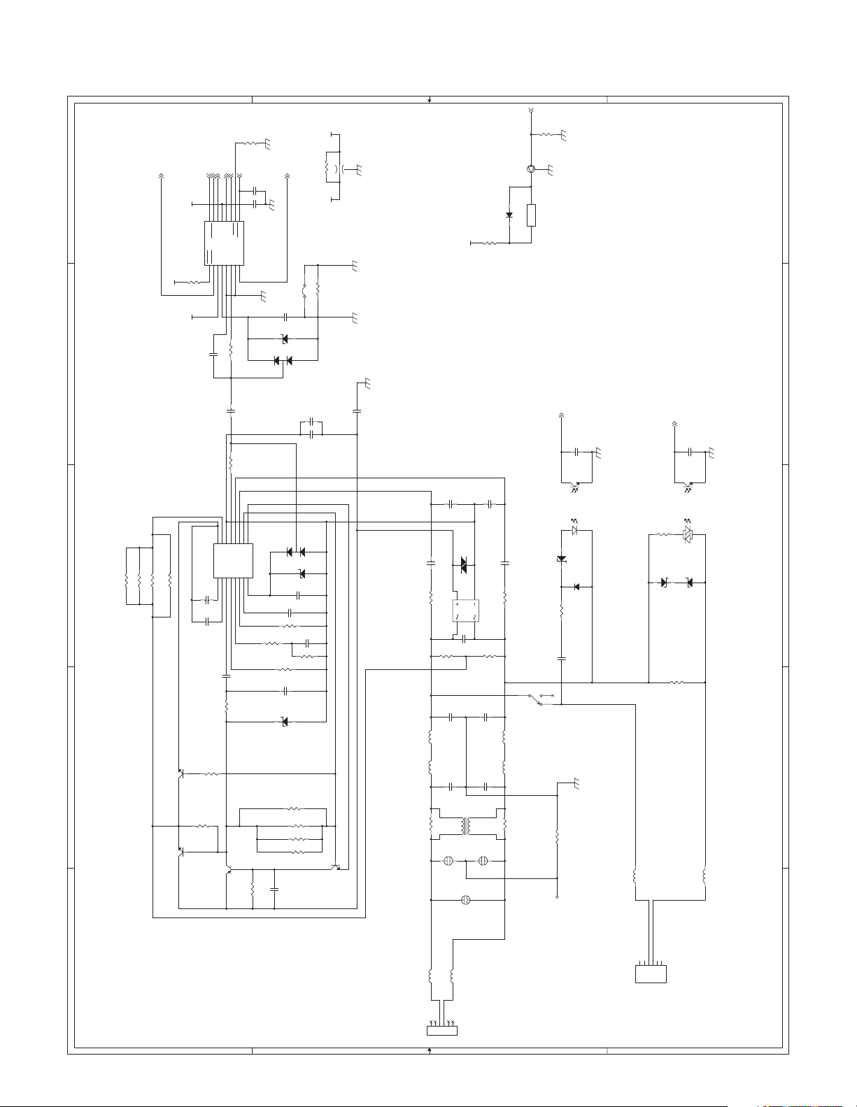
[6] CIRCUIT DIAGRAM
1. FAX MAIN PWB
4
R1000
10K
ABITCLK
ASPCLK
ARXD
ATXD
AFERST_L
DAA3.3V
0R
R10
DAA3.3V
DAA3.3V
Primary side Secondary side
R12 1.78kF 2W(N.M.)
Q2
34
2SD1733
1
R11
EC
B
2SC4548(E)
MCLOCK
1234567
MCLK
OFHK
IC2
C2
10pF/50V
IC1
C14
C13
B1uF/16V
100kF(1608)
VD
SDO
SCLK
FSYNC
GNDVAM0
RGDT/FSD
R3
C3
1234567
QE2
DCT
IGND
FILT2
B0.22u/16V
C1006
B0.1u/50V
150(1608)
R1017
Q1000
2SA1759
E C
89
SDI
RESETAOUT
FC/RGDT
M1
C1A
10111213141516
10 1/10W
150p/AC250V
R4
10 1/10W
89
QB
C1B
RNG1
RNG2
REF
REXT2
REXTRXFILT
VREG2
11121314151610
R1018
2.2K 1/10W
B
1000pF
C1000
C9
B0.1u/16V
Si3021-FS
QEVREG
Si3015-FS
R1013
5.36KF 1/4W
5.36KF 1/4W
R1014
R1015
RGDT-
5.36KF 1/4W
R1016
Q1
K
120K
DAAGND
DAAGND
DAAGND
K
RD43FM
SPOUT
AK
DAN217
D2
R1001 78.7F(1608)
ZD1001
C1005
B0.01u/50V
C1 B0.22u/10V
D1
AK
TPGND 0R(N.M.)
ZD1 RLZ5.6
A
C1004 B1800p/50V
DAN217
C12
C1002 B0.1u/16V
R1003 402F(1608)
R7
0R
R1 0R(N.M.)
C11
(3216) N.M.
(2125)
B0.022u/250V
A
ZD1000 RLZ5.6
C1001 B0.1u/16V
R1002 9.31kF(1608)
C1003 B0.68u/16V
R5 215F(1608)
R28 1.78kF 2W(N.M.)
R1027 5.36kF 1/4W
R1028 536kF 1/4W
R1019 5.36kF 1/4W
+3.3V DAA3.3V
B
Q1001
2SC4548(E)
3
FB2
MEM2012(N.M.)
2
1 3
C10
E C
DAAGND
GND
DAAGND
DAAGND
150p/AC250V
DIP
C1009
B560p/250V
R1020
56k 1/10W
L1
TWKA-221KNP
FB1
BLM31A601S
R1022
0R(N.M.)
+24V
B3900p/16V
C1007
VA1
12
D3
3 4
C15
R13 10M
2200pF(KH)
C4
C7
1000p/AC250V(NM)
FL4
ST110AV
DSS-401M
SA2
DSS-401M
SA3
D1000 1SS355
R1029
0R (1608)
B3900p/16V
C1008
DSS401M(N,M.)
R1021
56k 1/10W
S1ZB60
B0.01u/250V(N.M.)
10M
R14
2200pF(KH)
C5
L2
TWKA-221KNP
FB3
BLM31A601S
C6
1000p/AC250V(NM)
DSS-401M
SA1
2
Q3
C1011
B560p/250V
R1023
0R(N.M.)
S
B
DTC123JKA
C
+-
RY1B
OUAZ-SH-124DZ
5 4
3
Secondary side
R45
10K
E
PG
CID_L
ZD2
MTZJ30B
R27
C26
1 2
RY1A
OUAZ-SH-124DZ
R1117
H1
GND
C25
PC1B
43
PC1A
TLP621
12
D4
1SS355
10k 1W
0.47uF/250V
0R(N.M.)
B1000p/50V
TLP621
DAAGND
GND
L6
SBT-0260
R30
ZD4
EXHKD_L
30 1/4W
HZS2A1
R29
PC2B
43
PC2A
ZD3
91 1/4W
1
C27
B1000p/50V
PC814X
PC814X
1 2
HZS2A1
L5
GND
SBT-0260
12345
A B C D E
FAX MAIN PWB (TEL/LIU) 1/6
4
3
L3
MJ1
SBT-0260
L1
12345
L4
L2
SBT-0260
6
MJ-62J-RD315/MJ-66J-RD315
2
LT1
LT2
BT1
TEL1
TEL2
MJ2
6
BT2
MJ-62J-RD315/MJ-66J-RD315
1
A B C D E
AR-FX9 CIRCUIT DIAGRAM 6 - 1
Page 54
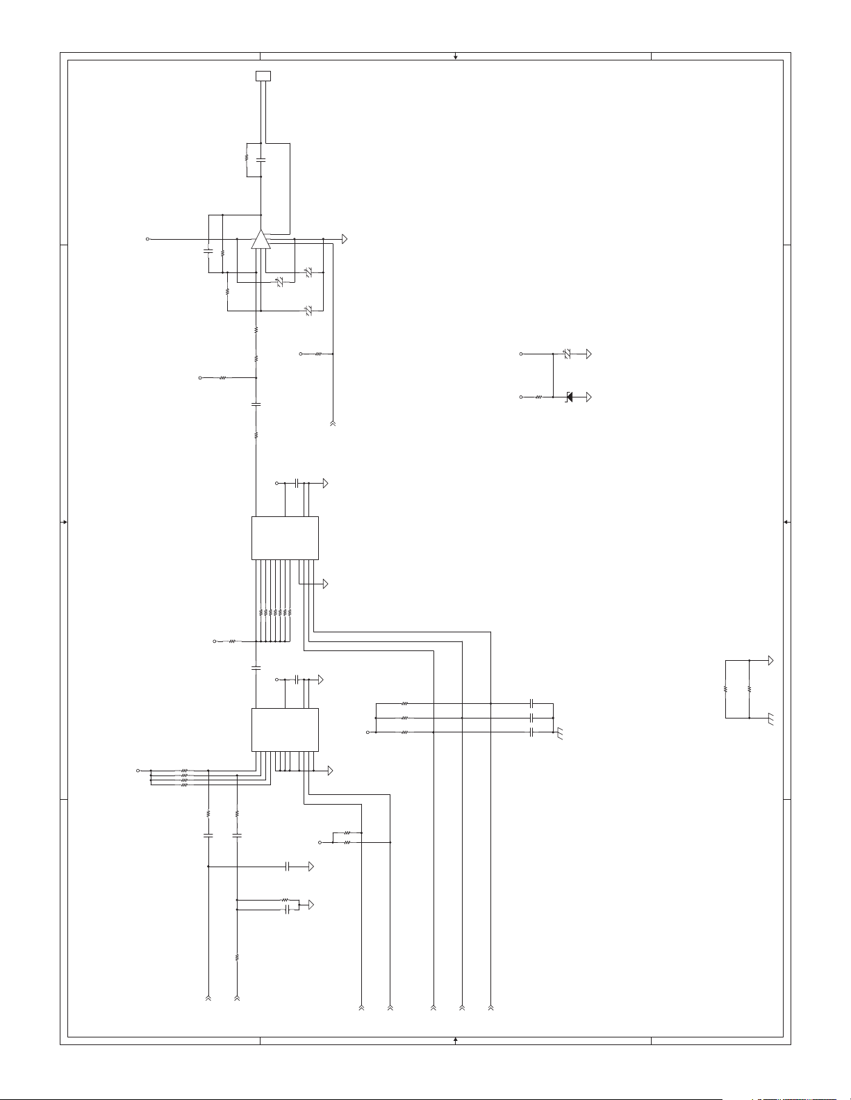
D
1
2
CN4
B2B-PH-K-S
SP
OUT
C41
10uF(N.M.)
R1057 0R
IC7
NJM2113M
5
8
7
R1056 200K
R1054 100k
R1051
10K(N.M.)
6
R1055
R1053
C1028
F0.1u/16V
1
4
3
2
3.3k
0R
C39
A4.7u/50V
+5V
C40
A4.7u/50V
C28
A4.7u/50V
R1052
+5V
C1031
100pF
Vref
C
AG
22k
B
C42
R1058
A4.7u/50V
AG
ZD5
HZS2C1
1k
AG
Vref
+5V
A
C37
C35
2200pF
F0.1u/16V
VEE
VSS
C
9
11
10
F0.1u/16V
VEE
VSS
C
9
11
10
+5V
BU4051BCF
AG
BU4051BCF
AG
SPMUTE
AG
AG
AG
R1040
R1042
3 2 1
AG
R1059 0R
R44 10k
R43 10k
+5V
10K
10K
R42 10k
C1030
F0.1u/16V(N.M.)
C1029
F0.1u/16V(N.M.)
C1027
F0.1u/16V(N.M.)
GND
R1060 0R
GND
R1050 3.3K
+5V+5V
3
1678
X
VDD
IC6
X0X1X2X3X4X5X6X7INHAB
15246
131415
12
R1043 33K
R1048 62K
R1046 200K
R1049 18K
R1047 5.1k
R1044 100K
R1045 10k
R1041 1M
Vref
C1026
F0.1u/16V
3
1678
X
VDD
IC4
X0X1X2X3X4X5X6X7INHAB
15246
131415
3.3K
R1035
F0.1u/16V
12
C1022
Vref
R1037 56k
R1034 56k
R1033 56k
R1039 56k
R1038
C1024
F0.1u/16V
1K
C1025
R1031
1.6k
AG
4 3 2 1
R1032 20k
BZ
FAX MAIN PWB (SPEAKER) 2/6
SPOUT
D
C1023
4700pF
VOLCNT_A
C
VOLCNT_B
VOL_A
VOL_B
VOL_C
B
A
4
AR-FX9 CIRCUIT DIAGRAM 6 - 2
Page 55

C50
C51
VSS
18pF(N.M.)
12pF(N.M.)
C54
F0.1u/16V
B
JP3 0R
GND
D
C
C52
12pF
X2
MC-306/DT-38 32.768KHz
14
23
C53
12pF
BAT+3.3V
384
XT-
VDD
A
454341393634323044424038353331
DQ15
DQ14
A19
A18
IC9
9
161748
A19A8A13A5A12
A20
A0
28
I/O6
DQ13
DQ12
DQ11
A17
A16
A15
1234567
A18
A17
A16A6A11
D5D6D7D4D3D2D1
25826
27
I/O3
I/O4
I/O5
DQ9
DQ8
DQ7
DQ6
DQ10
A14
A13
A12
A11
A10A9A8A7A6A5A4A3A2A1A0
A14
A15
D0
212223
I/O0
I/O1
I/O2
D5D7D0D4D1D6D2
D3
DQ5
DQ4
8
18192021222324
A10A3A9
A17
9
DQ3
DQ2
A7
F_RYBY
29
15134712372746
DQ1
DQ0
BYTE
RY/BY
A4
A2
BAT
VCC
25
A1
C46
+
C47
+3.3V
VPP
VCC
CE
262811
CS_FL
F_WP
22uF/16V
F0.1u/16V
24
VSS
C48
OEWEWP
RP
RESETL
F0.1u/16V
GND
GND
14
C1032
GND
10
A21
100pF
CLK
5 2
RTC_CLK
I/O-
CE XT
RTC_CE0H
L_BT-
SM8578BV
R56
10k
GND
C_BT
IC11
DATA
716
R55
10k
GND
RTC_DATA
NC
MBM29LV160BE90TN
R1030
75
GND
WE
A0A1A2A3A4
IC10
10 29
A16
A13
A14
A15
A16 I/O7
4117
A13A5A10
A15
A14A3A12A1A6A7A8
12131
A8NCA12
A11
A10
A9
3
2
A11
A9
4 3 2 1
FAX MAIN PWB (SRAM & FLASHROM(16M)) 3/6
D[7:0]
A[21:0]
D
CE1
A5A6A7
CE2
OE
151413
32
A0A2A4
WEL
CS_S1L
CS_S0L
OEL
+3.3V
C
BAT+3.3V
ZD6
R59
TR3
KTA1504
UDZ2.0B
0R
GND
4
GND
IC12
PST3426
OUT
VCC NC
1
2 3
D1001
1SS355
R57
1k
C45
F0.1u/16V
GND
R50
20k
R48
R49
1k
R47
360
B
R58
1k
TR2
KTC3875
R46
100k
BT1
CR2477(3V)
12
560
TR4
DTC363EKA
B
E
GND
C
CS_S1L
GND
TR1
KTA1504
R51
+3.3V
GND
1k
A
IS62WV1288BLL
5
6
2019181716
30
3 2 1
GND
4
AR-FX9 CIRCUIT DIAGRAM 6 - 3
Page 56
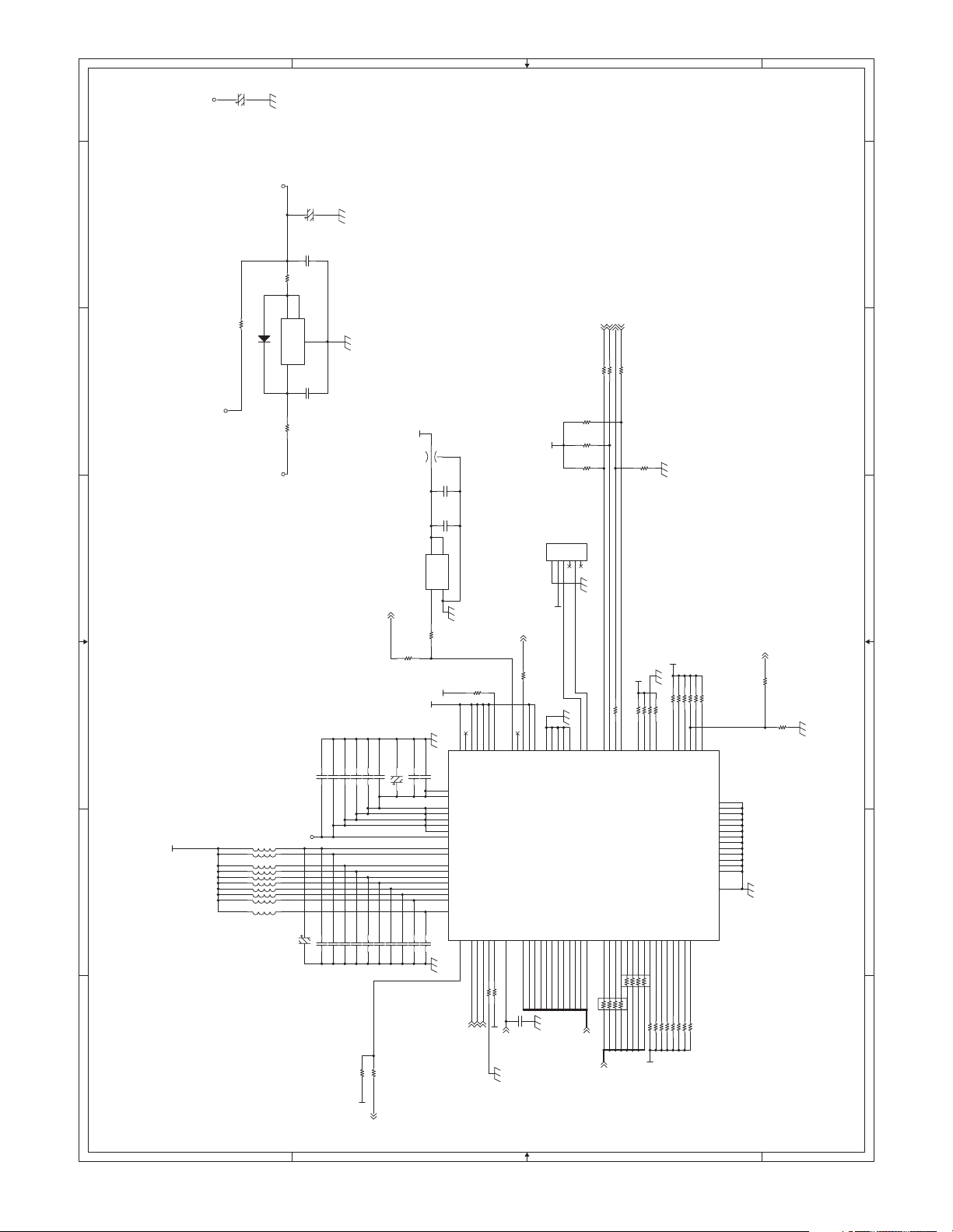
ABITCLK
R6 100
R9 100
ASPCLK
ATXD
B
ARXD
R2 100
D
C49
A47u/25V
+3.3V
R1063 0R(3216)
GND
MDM3.3V+5V
R1036
0R(3216 N.M.)
D5 1SS355(N.M.)
IC5 LM1117-3.3V(N.M.)
GND
C36
A47u/25V
C1034
F0.1u/16V
2
4
OUT1
OUT2
GND
1
C38
F0.1u/16V(N.M.)
GND
IN
3
C
A
+3.3V
F0.1u/16V
C1019
F0.1u/16V
F0.1u/16V
C19
F0.1u/16V
R21 0R
MDM_IRQ
CLKIN
C16
C22
F0.1u/16V
R16
A22u/16
C23
F0.1u/16V
+3.3V
FL10
ZJSR5101(22000p)
C32
F0.1u/16V
C31
C470/16V
4
VDD
OUT OE
GND
X1
3 1
2
SCO10-24.576000MHz-3.3V
R15 33
33
MDM3.3V
MDM3.3V
GND
C1013
F0.1u/16V
C1014
F0.1u/16V
52
53
9
42
54
55
78
34
IC3
C24
F0.1u/16V
C17
F0.1u/16V
GND
C
GND
R1024
47K
262728
36
TMS
PLLON
DBGMOD
NDBGREQ
REGOUT
REGOUT
VDD2
VDD2
VDD2
VDD2
VDD2
VDDREG
VDDREG
VDD3
VDD3
VDD3
VDD3
VDD3
VDD3
VDD3
AVDD
NDPCS
NDPRD
T3IRQ
1
7574737271
CS_ML
OEL
2930313233
TDI
TCK
NDPWR
NUB
R17 47K
WEL
R18 47K
MDM3.3V
TDO
NLB
39
CXIN
NRESET
41
M_RESETL
GND
3837434445
MCLOCK
R1006 75
51
CNT
LON
CXOUT
CLKOUT
DPA09
DPA10
DPA11
969798
100
A11
A10A9A8A7A6A5A4A3A2A1A0
C1018
100pF
R41 0R(N.M.)
C1017
F0.1u/16V
C1015
F0.1u/16V
F0.1u/16V
C1020
F0.1u/16V
F0.1u/16V
C21
F0.1u/16V
C34
F0.1u/16V
C33
F0.1u/16V
C1016
C18
MDM3.3V
C1021
+1.8V
FL1
FL2
FL12
FL11
FL7
FL5
FL3
FL9
FL8
FL6
C8
A22u/16V
C20
7 6 5 4 3 2 1
R25 4.7k
+3.3V
FAX MAIN PWB (MN195006Q) 4/6
D
CN1
DPA08
GND
+3.3V
12345
4647484950
SCANNT
MINTEST
DPA06
DPA07
+3.3V
INTEST
DPA05
9192939495
MODE0
DPA04
88
GND
MODE1
DPA03
878690
DPA02
R1005
47K
R8
47K
R1004
47K
6
A2-6PA-2.54DSA(NM)
GND
EYECLK
EYEDAT
ABITCLK
MN195006E
DPA01
DPA00
DPD15
25
85
84
33
BR1
123
A[21:0]
D[7:0]
R1007 0R
63626160595857
ATXD
ASPCLK
DPD13
DPD14
222324
678
D5
20
BR2
4 5
ARXD
DPD12
33
123
DPD11
R1009 47k
DPD10
678
D1D3D2D4D6D7D0
R1008
47K
MDM3.3V
R1010 47k
R1012 47k
696876
BSPCLK
BBITCLK
DPD08
DPD09
4 5
R33 47K
MDM3.3V
B
R1011 47k
BTXD
DPD07
R34 47K
676665
BRXD
DPD06
DPD05
101112131415161819
R35 47K
GND
R36 47K
GND
MDM3.3V
R23 47K
GPIO0
DPD03
DPD04
R37 47K
R24 47K
R38 47K
77
R26 47K
GPIO1
DPD02
R39 47K
R22 47K(NM)
GPIO2
DPD01
2345678
R40 47K
R1025 47K
GPIO3
DPD00
R1026 47K
8382818079
GPIO4
GPIO5
VSS
VSS
VSS VDD2
VSS
VSS
VSS
VSS
VSS
VSS
VSS
VSS
VSS
VSS
AVSS
AFERST_L
R20 0R
R19
47K
GND
17 21
40
56
64
70
89
99
35
GND
6 5 4 3 2 1
7
A
AR-FX9 CIRCUIT DIAGRAM 6 - 4
Page 57
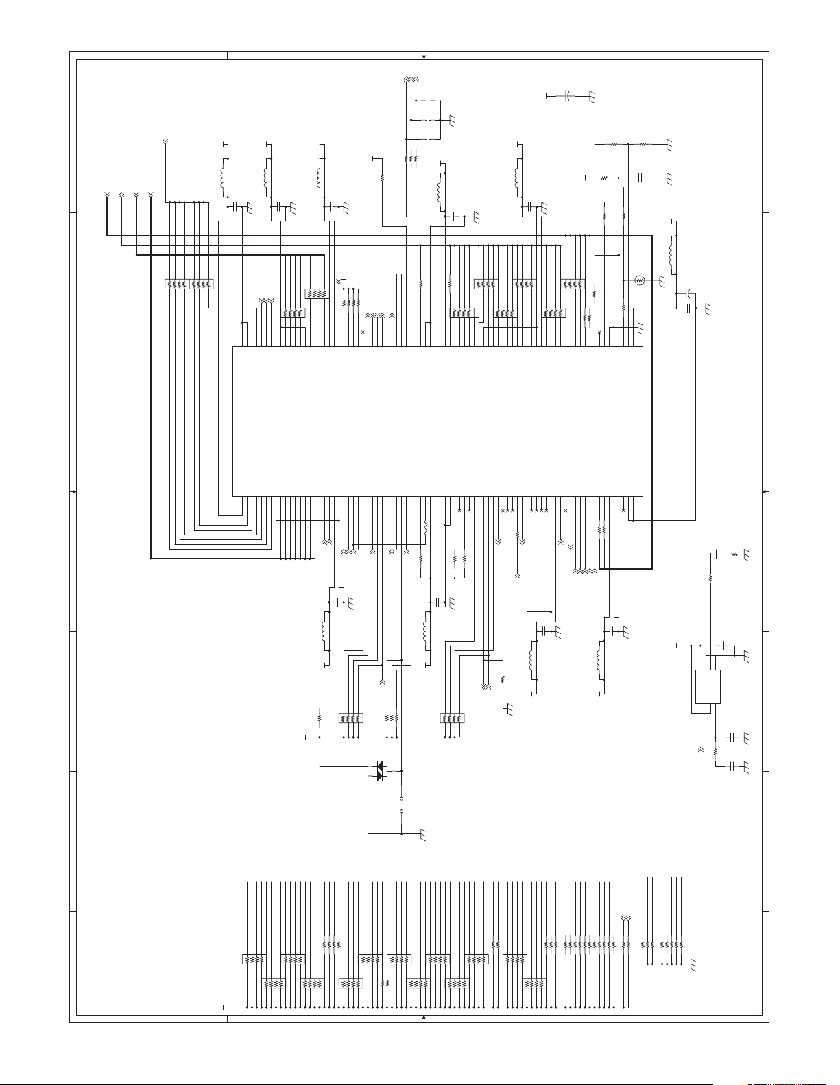
D[7:0]
A[21:0]
D
MCU_D[7:0]
PB_A[7:0]
PB_D[7:0]
PB_D1
PB_D0
PB_D2
PB_D3
PB_D4
PB_D5
PB_D6
PB_D7
+3.3V
FL20 (N.M.)
C65
F0.1u/16V
+3.3V
FL18 (N.M.)
B
A47u/25V
C68
+
C63
+3.3V
F0.1u/16V
GND
+3.3V
+3.3V
+3.3V
GND
R1091
10K
R1090
10K
(N.M.)
C1048
100pF
R1093
10K
CLKIN
R32 0R(N.M.)
R1092 10K
C
OEL
WEL
CS_ML
C1043
18pF
GND
18pF
C56
F0.1u/16V
+3.3V
+3.3V
FL13 (N.M.)
C55
F0.1u/16V
GND
R1071
GND
10K(N.M.)
C1044
18pF
+3.3V
R1066 100
R54 100
R1069 100
C62
F0.1u/16V
FL19 (N.M.)
GND
+3.3V
FL14 (N.M.)
GND
A
GND
GND+3.3V
+3.3V
BR18
MNR04 47
123
CS_S0L
CS_FL
129
130
131
RTC_SDATA
FAXCS_N_02
FAXCS_N_01
FAXCS_N_00
FGPI_04
FGPI_03
FGPI_02
FGPI_01
HS2L
CID_L
RGDT-
R1106 10K
R1115 10K
DA204U
CS_OP1L
CS_OP2L
126
127
128
FAXCS_N_04
FAXCS_N_03
FGPI_00
FGPIO_07
HS1L
R1114 10K
JP2
A21
R53 0R
123
124
125
FAXOE_N
FAXWR_N
FAXADD_21
FAXCS_N_05
FGPIO_06
FGPIO_05
FGPIO_04
TCK
F_RYBY
R1113 10K
T2B-SQ
121
122
GND
GND
uPD65944GM-P07-JED-A
TRST
VDD
40
R68 10k C1033
C73
FL25 (N.M.)
+3.3V
678
678
123
4 5
4 5
BR17
MNR04 47
160
IC13
135
MCU_CEL
MCU_INT
155
156
157
158
159
GND
GND
CPU_CS_N
CPU_INT_N
PB_DAT_07
PB_DAT_06
PB_DAT_05
PB_DAT_03
PB_DAT_01
VDD
PB_DAT_04
PB_DAT_02
246119
MCU_OEL
BR4
MNR04 0R
152
153
154
VDD
CPU_RD_N
PB_DAT_00
TESTMODE0
7
PB_A7
MCU_D0
MCU_D3
MCU_D2
MCU_D1
678
123
149
150
151
GND
CPU_DT_02
CPU_DT_01
CPU_DT_00
PB_ADDR_05
PB_ADDR_07
PB_ADDR_06
PB_ADDR_04
101214
PB_A3
PB_A6
PB_A4
PB_A5
WEL
+3.3V
MCU_D7
MCU_D6
MCU_D5
MCU_D4
678
BR3
MNR04 0R
123
4 5
4 5
143
144
145
146
147
148
GND
CPU_DT_07
CPU_DT_06
CPU_DT_05
CPU_DT_04
CPU_DT_03
PB_ADDR_03
PB_ADDR_01
PB_ADDR_02
PB_ADDR_00
PB_CE2_N
PB_CE1_N
13
15
16
1718202122826272829303132333435363738394243444546474849505152
PB_A1
PB_A0
PB_A2
PB_CS1L
FL21 (N.M.)
+3.3V
R1087 10K
+3.3V
141
142
VDD
GND
PB_AE0_N
VDD
19
PB_AE0L
R1073 10K
R1077 10K
138
139
140
UART_RTS
FAXWRIN_N
GND
PB_WR_N
23
PB_WEL
C64
F0.1u/16V
BR30
123
R1074 10K
R1078 10K
136
137
UART_SIN
UART_CTS
UART_SOUT
PB_OE_N
RESET_N
WAKE_UP
24
25
WAKE_UP
PB_OEL
RESETL
GND
MNR14 10K
678
4 5
RTC_CE0H
134
135
RTC_CE
RTC_ION
FGPI_07
FGPI_06
RTC_CLK
RTC_DATA
132
133
RTC_SCLK
FGPI_05
EXHKD_L
D6
A20
R60 100
119
120
VDD
FAXADD_20
GND
GND
41
F0.1u/16V
BR29
123
A17
A19
A18
BR12
MNR04 100
678
123
116
117
118
FAXADD_18
FAXADD_19
TMSNCTDI
R1112 10K
R1111 10K
GND
MNR14 10K
678
4 5
A16
A15
123
4 5
113
114
115
FAXADD_14
FAXADD_15
FAXADD_16
FAXADD_17
TDO
FGPIO_03
FGPIO_02
A14
A13
A11
A10
678
4 5
BR14
MNR04 100
678
BR13
MNR04 100
123
107
108
109
110
111
112
GND
FAXADD_10
FAXADD_11
FAXADD_12
FAXADD_13
FGPIO_01
FGPIO_00
TELELIN
BEEP_O_V1
BEEP_O_V2
53
54555657585960616263646566
BZ
R1105 10K
L_BT-
C_BT
123
BR15
4 5
104
105
106
FAXADD_07
FAXADD_08
FAXADD_09
FGPO_15
FGPO_14
FGPO_13
R1104 100
M_RESETL
GND
A5A6A7A4A8A9A12
678
4 5
MNR04 100
101
102
103
FAXADD_04
FAXADD_05
FAXADD_06
FGPO_12
GND
FGPO_11
S
FL24 (N.M.)
+3.3V
A3
123
100
VDD
GND
FGPO_10
FGPO_09
C72
A2A1A0
BR16
MNR04 100
678
4 5
979899
FAXADD_01
FAXADD_02
FAXADD_03
FGPO_08
GND
VDD
F0.1u/16V
D1D3D5
D2
D0
678
123
BR28
MNR04 100
FAXADD_00
FAX_DATA_02
FAX_DATA_01
FAX_DATA_00
FGPO_04
FGPO_07
FGPO_06
FGPO_05
67
SPMUTE
F_WP
VOL_C
GND
D4
4 5
R1094 0R
R64 100
R65 100
90
91929394957496
89
FAX_DATA_05
FAX_DATA_04
FAX_DATA_03
FGPO_01
FGPO_02
FGPO_03
7271706968
VOL_B
VOLCNT_B
VOL_A
84
TMD1
TMD2
TOUT
TMD0
TESTB
TMD0_OUT
FAX_DATA_06
FGPO_00
FAX_DATA_07
VDD
GND
XIN
73757677787980 81
R67 100
D7
D6
VOLCNT_A
C71
F0.1u/16V
FL23 (N.M.)
+3.3V
R1095 0R(N.M.)
8285868788
83
CLKSEL
SYSCLK_IN
XOUT
GND
GND
10kΩ
FL22 (N.M.)
A47u/25V
C70
+
GND
C69
GND
GND VDD
F0.1u/16V
VDD
IC8
Xin
123
CLKIN
R52 0R
678
S0
FSOUT
XoutS1LF VSS
4 5
R31 510 (N.M.)
R1096
100pF
C1049
C44
F0.1u/16V (N.M.)
P2782A-08SR
C30
270pF(N.M.)
C29
F0.1u/16V (N.M)
GND
75Ω
GND GND GND
GND
MCU_D0
MCU_D2
MCU_INT
MCU_D7
PB_AE0L
PB_WEL
PB_OEL
PB_D7
PB_D3
PB_D2
PB_D0
PB_A5
PB_A7
PB_D6
PB_D5
PB_D4
PB_D1
PB_A6
PB_A4
BR24
MNR04 22K
678
4 5
123
BR23
MNR04 22K
678
MNR04 iN.M.)
678
123
4 5
4 5
BR22
8 7 6 5 4 3 2 1
123
FAX MAIN PWB (ASIC_NEW_CILF) 5/6
D
+3.3V
PB_A3
123
D7
D6D3D2D0A21
R1083 22K
R1089 22K
BR27
123
MNR04 10K
123
678
4 5
D1D4D5
BR26
MNR04 10K
678
4 5
PB_A2
PB_CS1L
PB_A0
PB_A1
R1082 22K
R1088 22K
BR25
MNR04 iN.M.)
678
4 5
A13
A10A9A8A7A5A4A2
A15
A16
A19
A20
A14
A18
A17
A12
A11
A6A3A0
BR7
MNR04 10K
BR9
MNR04 10K
678
678
BR8
MNR04 10K
BR10
123
4 5
123
R61 10K
R62 10K
MNR04 10K
123
4 5
123
123
678
4 5
678
4 5
C
A1
BR11
MNR04 10K
678
4 5
RESETL
WAKE_UP
R1076 22K(N.M.)
R1080 22K(N.M.)
MCU_D6
BR5
123
MCU_D5
MCU_D4
MCU_D3
MNR04 (N.M.)
678
BR6
4 5
123
B
MCU_CEL
MCU_D1
R1065 22K
R1081 22K
MNR04 (N.M.)
678
4 5
MCU_OEL
WEL
R1075 10K
R1086 22K
OEL
R1062 10K
CS_OP1L
CS_OP2L
R1070 10K(N.M.)
R1068 10K(N.M.)
CS_FL
R1067 10K
CS_ML
R1072 10K
CS_S0L
F_RYBY
R1108 10K
R1079 10K
CID_L
EXHKD_L
SPMUTE
VOL_B
VOL_A
VOLCNT_B
VOLCNT_A
HS1L
HS2L
M_RESETL
R1102 10K(N.M.) R66 100
R1109 10K
R1110 10K
VOL_C
M_RESETL
RESETL
R71 10K
R72 22K
R1101 10K(N.M.)
R1097 10K(N.M.)
R1100 10K(N.M.)
R1098 10K(N.M.)
R1099 10K(N.M.)
R1103 10K(N.M.)
R1107 10k
R1084 10k
GND
A
7 6 5 4 3 2 1
8
AR-FX9 CIRCUIT DIAGRAM 6 - 5
Page 58

D
GND
IN5V IN3.3V
R1116 0R (1608 N.M.)
123
4
CN5
B4B-PH-K-S(N.M.)
MCU_D[7:0]
C
B
A
TP3.3V
+3.3V+5V+24V
IN3.3VIN5V
TP5V
LC3S-Y(N.M.)
LC3S-Y(N.M.)
TP24V
FL15
ZJSR5101(22000p)
FL16
ZJSR5101(22000p)
C61
LC3S-Y(N.M.)
+
FL17
ZJSR5101(22000p)
+
+
A47u/35V
C57
1000p(N.M.)
F0.1u/16V
C58
A47u/25V
C59
GND
F0.1u/16V
C43
A47u/25V
C60
PB_D[7:0]
PB_D2
PB_D5
PB_D4
PB_D7
PB_D3
PB_D6
PB_D0
MCU_OEL
MCU_CEL
MCU_D2
MCU_D3
MCU_D4
MCU_D6
MCU_D7
MCU_D1
MCU_D5
MCU_D0
GND
GND
GND
PG
123456789
CN3
FB12
MNR04 100
678
123
4 5
123
1011121314151617181920
FB8
MNR04 100
678
FB7
MNR04 47
678
123
4 5
4 5
20FE-BT-VK-N
MCU_INT
R1064 0R
R1085 0R
C1042 10p/50V(N.M.)
GND
C1041 10p/50V(N.M.)
C1039 10p/50V(N.M.)
C1037 10p/50V(N.M.)
C1040 10p/50V(N.M.)
C1038 10p/50V(N.M.)
C1046 10p/50V(N.M.)
C1047 10p/50V(N.M.)
C1035 10p/50V
GND
C1045 10p/50V
C1036 10p/50V
PB_D1
C1069 33pF
C1068 33pF
C1067 33pF
C1066 33pF
C1065 33pF
C1064 33pF
C1063 33pF
C1062 33pF
FB11
MNR04 33
123456789
CN2
123
GND
678
4 5
FB10
MNR04 33
678
123
PB_A[7:0]
PB_A7
PB_A6
PB_A5
PB_A3
PB_A4
PB_A2
PB_A1
PB_A0
678
BR20
MNR04 0
123
4 5
678
BR19
MNR04 0
123
4 5
FB9
MNR04 33
FB5
MNR04 0R
678
123
4 5
1011121314151617181920212223242526
678
4 5
123
FB6
MNR04 33
678
123
4 5
PB_WEL
PB_CS1L
MDM_IRQ
PB_AE0L
RESETL
PB_OEL
BR21
MNR04 33
678
123
4 5
C1054 33pF
C1055 33pF
C1057 33pF
C1060 33pF
C1053 33pF
C1052 33pF
C1051 33pF
C1050 33pF
4 5
R63 33
GND
C1061 33pF
GND
C1058 33pF
C1056 33pF
C1059 100pF
C67 1000pF
C66 10p/50V
7 6 5 4 3 2
R69 100Ω
R70 0R
26F-E-BT-VK-N
(N.M.)
R1061 0R
GND PG
8 7 6 5 4 3 2
8
FAX MAIN PWB (MCU I/F) 6/6
D
C
B
AR-FX9 CIRCUIT DIAGRAM 6 - 6
A
Page 59

2. FAX OPERATION
1/1
KEY419
SPKK
KEY409
E
KEY412
OT1K
KEY402
OT2K
OT3K
KEY403
KEY404
KEY413
KEY414
D
KEY415
OT4K
KEY405
OT5K
MEMK
KEY406
KEY407
KEY416
KEY417
CSK
OT6K
OT7K
OT8K
OT9K
SFTK
RESOK
KEY401
KEY420
KEY421
KEY410
RMODK
E
D
BCK
R/PK
REPK
C
D401
KEY418
1SS133
S/SK
D402
KEY408
1SS133
CONTK
D403
KEY411
1SS133
FDUPK
B
LED401
LS
LED403
MEM
LED402
SHIFT
C
B
F-KEYIN6
F-KEYIN1
F-KEYSC3
F-KEYIN8
F-KEYIN4
F-KEYIN7
F-KEYIN2
F-KEYIN3
A
FAX OPERATION PWB
F-KEYIN5
18
CN401
4 4
LED_V3
F-KEYSC2
F-KEYSC1
LED_V2
LED_V1
DATA1
1234567891011121314151617
18FE-ST-VK-N
3 3
2 2
A
1 1
AR-FX9 CIRCUIT DIAGRAM 6 - 7
Page 60

Memo
Page 61

q
PARTS GUIDE
CODE:00ZARFX9//P1E
FAX unit
1
Packing Material & Accessories
2
FAX operation PWB
3
Modem control PWB
■
Index
MODEL
(For North America)
CONTENTS
AR-FX9
Because parts marked with "!" is indispensable for the machine safety maintenance and poeration, it must
Be replaced with the parts specific to the product specification.
This document has been published to be used for
SHARP CORPORATION
after sales service only.
The contents are subject to change without ontice.
Page 62

DEFINITION
The definition of each Rank is as follows and also noted in the list
Rank A : Maintenance parts, and consumable parts which are not included in but closely related to maintenance parts
Rank B : Performance/function parts (sensors, clutches, and other electrical parts), consumable parts
Rank E : Unit parts including PWB
Rank D : Preparation parts (External fitting, packing, parts packed together)
Rank C : Parts other than the above (excluding sub components of PWB)
Because parts marked with "!" is indispensable for the machine safety maintenance and operation, it must be replaced with
the parts specific to the product specification.
F Other than this Parts Guide, please refer to documents Service Manual(including Circuit Diagram)of this model.
F Please use the 13 digit code described in the right hand corner of front cover of the document, when you place an order.
F For U.S. only-Use order codes provided in advertising literature. Do not order from parts department.
Packing Material & Accessories
1
PRICE
NEW
NO. PARTS CODE
DHAI-0430QSZZ AH C FAX harness A
DHAI-0431QSZZ AH C FAX harness B
DHAI-0439QSZZ AC N C Earth harness
1
QCNW-7197XCZZ AH C Line cable
RCORF0018QSZZ AR C FFC core
TCADZ0330QSZZ AF N D Instral manual card
XHBSE30P06000 AA C Screw(3×6)
2 SSAKH3013CCZZ AA D Vinyl bag(120×220)
3 TINSE1222QSZZ AY N D Operation manual
4 CPNLH0032QS02 AY N B Operation panel (ENGLISH)
5 SSAKA2342QCZZ AA D Vinyl bag(W250×D350)
7 CPWBX0154QSE2 BY N E Modem control PWB unit
8 LHLDZ0108QSZZ AN C FAX PWB holder
9 LPLTM0353QSZ1 AF C Connector plate
10 SPAKA399ACCZZ AB D Vinyl bag
13 SPAK-547ECCZZ AB D Vinyl bag(125×280mm)
14 LPLTM0357QSZ1 AF N C Speaker plate
17 SSAKA0006UCZZ AA D Vinyl bag(50×60mm)
18 RSPA00002QSZZ AK B Speaker
19 PGSK-0030QSZZ AH N C Gasket
20 PSHEZ0478QSZZ AG N C EMI measure sheet
21 LX-HZ0002QSZZ AC N C Screw
22 PCOVP0102QSZZ AF N C FAX PWB cover
23 XHBSE30P06000 AA C Screw(3×6)
24 CPWBF0152QSE1 AS N E FAX operation PWB
25 JBTN-0072QSZZ AG C One-touch Key
26 GCOV-0059QSZZ AG N D Option cover
27 XEBSD30P08000 AA C Screw(3×8)
RANK
MARK
PART
RANK
DESCRIPTION
– 1 –
Page 63

Packing Material & Accessories
1
24
27
26
27
13
25
14
21
18
19
1
17
2
3
4
5
23
7
8
20
9
10
23
22
23
PRP01991
FAX operation PWB
2
PRICE
NEW
NO. PARTS CODE
1 QCNCW1132LC1H AD C Connector(18pin) [CN1]
QSW-P0001ESZZ AC B Tact swtch(SKQNAB010) [S/SK,SPKK,BCK,R/PK,RESOK]
QSW-P0001ESZZ AC B Tact swtch(SKQNAB010) [OT1K,MEMK,CONTK,OT7K,OT8K]
2
QSW-P0001ESZZ AC B Tact swtch(SKQNAB010) [OT9K,SFTK,FDUPK,OT6K,RMODK]
QSW-P0001ESZZ AC B Tact swtch(SKQNAB010) [REPK.OT2K,OT3K,OT4K,OT5K,CSK]
3 VHD1SS133++-1 AA B Diode(1SS133) [D1,D2,D3]
4 VHP1LHLE-002A AC B LED(Green)(LTL-1LHLE-002A) [SHIFT,LS,MEM]
(Unit)
901 CPWBF0152QSE1 AS N E FAX operation PWB
Modem control PWB
3
NO. PARTS CODE
2 QCNCM7014SC0B AD C Connector(2pin) [CN4]
3 QCNCW0096QSZZ AD N C Connector(20FE-BT-VK-N) [CN3]
4 QCNCW1124LC2F AD C Connector(26FE-BT-VK-N)(26pin) [CN2]
QJAKT0001FCZZ AD C Connector(MJ-62J-RD315) [MJ2]
5
QJAKT0001FCZZ AD C Connector(MJ-62J-RD315) [MJ1]
7 QPIN-0002GCZZ AC C Junper pin(T2B-SQ) [JP2]
9 RCILZ0015QSZZ AD C Coil(TWKA-221K) [L1,L2]
11 RCILZ0089FCZZ AG C Coil(ST110AV) [FL4]
14 RCORF1003MCZZ AC C Core(BLM31AJ601SN1) [FB1,FB3]
15 RCRSP6676RCZZ AG B Cristal(32.768KHz) [X2]
17 RFILN2011SCZZ AC C Coil(SBT-0260) [L3,L4,L5,L6]
18 RFILZ0004QSZZ AM C Filter(ZJSR5101-223) [FL10,FL15,FL16,FL17]
19 RMPTR4000ACZZ AB B Block resistor(0Ω×4) [BR3,BR4,BR19,BR20,FB5]
20 RMPTR4101ACZZ AB B Block resistor(100Ω×4) [BR12,BR13,BR14,BR15,BR16,BR28,FB8,FB12]
RANK
PRICE
RANK
MARK
NEW
MARK
PART
RANK
PART
RANK
DESCRIPTION
DESCRIPTION
– 2 –
Page 64

Modem control PWB
3
PRICE
NEW
NO. PARTS CODE
21 RMPTR4103ACZZ AB B Block resistor(10KΩ×4) [BR7,BR8,BR9,BR10,BR11,BR26,BR27]
22 RMPTR4103ACZZ AB B Block resistor(10KΩ×4) [BR29,BR30]
23 RMPTR4223ACZZ AB B Block resistor(22KΩ×4) [BR22,BR23]
24 RMPTR4330ACZZ AB B Block resistor(33Ω×4) [BR1,BR2,FB6,FB9,FB10,FB11,BR21,]
25 RMPTR4470ACZZ AB B Block resistor(47Ω×4) [FB7,BR17,BR18]
26 RRLYD1224QCZZ AH B Relay(24V OUAZ-SH-124DZ) [RY1]
28 UBATI0014FCZZ AN B Battery(CR2477-H01) [BT1]
29 VCCCCY1HH100D AA C Capacitor(50WV 10pF) [C1035,C1036,C1045]
30 VCCCCY1HH101J AA C Capacitor(50WV 100pF) [C1018,C1031,C1032,C1048,C1059]
31 VCCCCY1HH180J AA C Capacitor(50WV 18pF) [C1033,C1043,C1044]
VCCCCY1HH330J AA C Capacitor(50WV 33pF) [C1050,C1051,C1052,C1053,C1054,C1055,C1056]
32
VCCCCY1HH330J AA C Capacitor(50WV 33pF) [C1057,C1058,C1060,C1061,C1062,C1063,C1064]
VCCCCY1HH330J AA C Capacitor(50WV 33pF) [C1065,C1066,C1067,C1068,C1069]
33 VCCCCZ1HH100D AA C Capacitor(50WV 10pF) [C66]
34 VCCCCZ1HH101J AA C Capacitor(50WV 100pF) [C67]
35 VCCCCZ1HH120J AA C Capacitor(50WV 12pF) [C52,C53]
38 VCEAGA1CW226M AB C Capacitor(16WV 22µF) [C8,C16,C46]
39 VCEAGA1EW476M AA C Capacitor(25WV 47uF) [C36,C49,C59,C60,C68,C70]
40 VCEAGA1HW475M AA C Capacitor(50WV 4.7µF) [C28,C39,C40,C42]
41 VCEAGA1VW476M AB C Capacitor(35WV 47µF) [C61]
42 VCFYJU2EA474K AD C Capacitor(250WV 0.47µF) [C26]
43 VCKYCY1CB104K AB C Capacitor(16WV 0.1µF) [C1001,C1002,C9]
44 VCKYCY1CB224K AE C Capacitor(16WV 0.22µF) [C1,C14]
VCKYCY1EF104Z AA C Capacitor(25WV 0.1µF) [C1021,C1019,C1014,C1013,C1020,C1017,C1015]
45
VCKYCY1EF104Z AA C Capacitor(25WV 0.1µF) [C1016,C1025,C1024,C1026,C1028,C1034]
46 VCKYCY1HB102K AA C Capacitor(50WV 1000pF) [C1000]
47 VCKYCY1HB103K AA C Capacitor(50WV 0.01µF/1608Type/B) [C1005]
48 VCKYCY1HB182K AA C Capacitor(50WV 1800pF) [C1004]
49 VCKYCY1HB222K AA C Capacitor(50WV 2200pF) [C1022]
50 VCKYCY1HB392K AA C Capacitor(50WV 3900PF) [C1007,C1008]
51 VCKYCY1HB472K AA C Capacitor(50WV 4700pF) [C1023]
VCKYCZ1CF104Z AB C Capacitor(16WV 0.1µF) [C17,C18,C19,C20,C21,C22,C23]
VCKYCZ1CF104Z AB C Capacitor(16WV 0.1µF) [C24,C32,C33,C34,C35,C37,C43]
52
VCKYCZ1CF104Z AB C Capacitor(16WV 0.1µF) [C45,C47,C48,C54,C55,C56,C58]
VCKYCZ1CF104Z AB C Capacitor(16WV 0.1µF) [C62,C63,C64,C65,C69,C72,C71,C73]
53 VCKYCZ1HB102K AA C Capacitor(50WV 1000pF) [C25,C27]
54 VCKYCZ1HB471K AA C Capacitor(50WV 470pF) [C31]
55 VCKYSU2EB222M AD C Capacitor(250WV 2200pF) [C4,C5]
56 VCKYTV1CB105K AC C Capacitor(16WV 1µF) [C13]
57 VCKYTV1CB684K AC C Capacitor(16WV 0.68µF) [C1003]
58 VCKYTW1HB104K AC C Capacitor(50WV 0.1µF) [C1006]
59 VHD1SS355//-1 AB B Diode(1SS355) [D4,D1001,D1000]
60 VHDDA204U//-1 AB B Diode(DA204U) [D6]
61 VHDDAN217//-1 AC B Diode(DAN217) [D1,D2]
62 VHDS1ZB60//-1 AC B Diode(S1ZB60) [D3]
63 VHEMTZJ30B/-1 AB B Diode(HZ3B1) [ZD2]
64 VHEHZS2A1//-1 AB N B Zener diode(HZS2A1) [ZD3,ZD4]
65 VHEHZS2C1//-1 AB B Zener diode(HZS2C1) [ZD5]
67 VHERLZ5.6B/-1 AC B Zener diode(RLZ5.6B) [ZD1]
68 VHEUDZ2.0B/-1 AC B Zener diode(UDZ2.0B) [ZD6]
69 VHI62WV12880C AQ N B IC(IS62WV1288BLL-55TI) [IC10]
70 VHI65944P07-1 AX N B IC(uPD65944GM-P07-JED-A) [IC13]
71 VHIBU4051BCF/ AF B IC(BU4051BCF) [IC4,IC6]
72 VHILV160B9N-1 BD B IC(MBM29LV160BE90TN) [IC9]
73 VHIN195006E-1 BK N B IC(MN195006E) [IC3]
74 VHINJM2113M-1 AG B IC(NJM2113-M) [IC7]
75 VHIPST3426U-1 AE B IC(PST3426) [IC12]
76 VHISI3015FS-1 AZ N B IC(Si3015-FSR) [IC1]
77 VHISI3021FS-1 AU N B IC(Si3021-FSR) [IC2]
78 VHISM8578BV-1 AK B IC(SM8578BV) [IC11]
81 VHPTLP621-1GB AF N B Photo coupler(TLP621) [PC1]
VHVDSS-401M// AH B Varistor(DSS-401M) [SA1,SA2]
83
VHVDSS-401M// AH B Varistor(DSS-401M) [SA3]
85 VRD-HT2EY300J AA C Resistor(1/4W 30Ω ±5%) [R30]
86 VRD-HT2EY910J AA C Resistor(1/4W 91Ω ±5%) [R29]
VRS-CY1JD000J AA C Resistor(1/16W 0Ω ±5%) [R1029,R1007,R1053,R1057,R1060,R1061,R1094]
87
VRS-CY1JD000J AA C Resistor(1/16W 0Ω ±5%) [R1059,R1095,R1064,R1085,C1049]
88 VRS-CY1JD101J AA C Resistor(1/16W 100Ω ±5%) [R1066,R1069,R1104]
89 VRS-CY1JD102J AA C Resistor(1/16W 1.0KΩ ±5%) [R1038,R1058]
VRS-CY1JD103J AA C Resistor(1/16W 10KΩ ±5%) [R1000,R1040,R1042,R1045,R1062,R1067,R1072]
VRS-CY1JD103J AA C Resistor(1/16W 10KΩ ±5%) [R1073,R1074,R1075,R1077,R1078,R1079,R1084]
VRS-CY1JD103J AA C Resistor(1/16W 10KΩ ±5%) [R1087,R1091,R1092,R1093,R1105,R1106]
90
VRS-CY1JD103J AA C Resistor(1/16W 10KΩ ±5%) [R1107,R1108,R1109,R1110,R1111,R1112,R1113]
VRS-CY1JD103J AA C Resistor(1/16W 10KΩ ±5%) [R1114,R1115,R45]
VRS-CY1JD103J AA C Resistor(1/16W 10KΩ ±5%) [R1096]
91 VRS-CY1JD104F AA C Resistor(1/16W 100KΩ ±1%) [R11]
92 VRS-CY1JD104J AA C Resistor(1/16W 100KΩ ±5%) [R1044,R1054]
93 VRS-CY1JD105J AA C Resistor(1/16W 1.0MΩ ±5%) [R1041]
94 VRS-CY1JD106J AA C Resistor(1/16W 10MΩ ±5%) [R13,R14]
95 VRS-CY1JD124J AA C Resistor(1/16W 120KΩ ±5%) [R1013]
RANK
MARK
PART
RANK
DESCRIPTION
– 3 –
Page 65

Modem control PWB
3
PRICE
NEW
NO. PARTS CODE
96 VRS-CY1JD151J AA C Resistor(1/16W 150Ω ±5%) [R1017]
97 VRS-CY1JD162J AA C Resistor(1/16W 1.6KΩ ±5%) [R1031]
98 VRS-CY1JD183J AA C Resistor(1/16W 18KΩ ±5%) [R1049]
99 VRS-CY1JD203J AA C Resistor(1/16W 20KΩ ±5%) [R1032]
100 VRS-CY1JD204J AA C Resistor(1/16W 200KΩ ±5%) [R1046,R1056]
101 VRSCY1JD2150F AA C Resistor(1/16W 215Ω ±1%) [R5]
102 VRS-CY1JD223J AA C Resistor(1/16W 22KΩ ±5%) [R1052,R1065,R1081,R1082,R1083,R1086,R1088,R1089]
103 VRS-CY1JD332J AA C Resistor(1/16W 3.3KΩ ±5%) [R1035,R1050,R1055]
104 VRS-CY1JD333J AA C Resistor(1/16W 33KΩ ±5%) [R1043]
VRS-CY1JD473J AA C Resistor(1/16W 47KΩ ±5%) [R1004,R1005,R1008,R1009,R1010,R1011,R1012]
106
VRS-CY1JD473J AA C Resistor(1/16W 47KΩ ±5%) [R1024,R1025,R1026]
107 VRS-CY1JD512J AA C Resistor(1/16W 5.1KΩ ±5%) [R1047]
108 VRS-CY1JD563J AA C Resistor(1/16W 56KΩ ±5%) [R1033,R1034,R1037,R1039]
109 VRS-CY1JD623J AA C Resistor(1/16W 62KΩ ±5%) [R1048]
111 VRS-CY1JD750J AA C Resistor(1/16W 75Ω ±5%) [R1030,R1006]
113 VRSCY1JD78R7F AA C Resistor(1/16W 78.7Ω ±1%) [R1001]
115 VRS-CZ1JD000J AA C Resistor(1/16W 0Ω ±5%) [R20,R21,R32,R53,R59,R70,R69]
VRS-CZ1JD101J AA C Resistor(1/16W 100Ω ±5%) [R2,R6,R9,R54,R60,R64,R65]
116
VRS-CZ1JD101J AA C Resistor(1/16W 100Ω ±5%) [R66,R67]
117 VRS-CZ1JD102J AA C Resistor(1/16W 1.0KΩ ±5%) [R48,R49,R51,R57]
VRS-CZ1JD103J AA C Resistor(1/16W 10KΩ ±5%) [R42,R43,R44,R55,R56,R61,R62]
118
VRS-CZ1JD103J AA C Resistor(1/16W 10KΩ ±5%) [R68,R71]
119 VRS-CZ1JD104J AA C Resistor(1/16W 100KΩ ±5%) [R58]
120 VRS-CZ1JD203J AA C Resistor(1/16W 20KΩ ±5%) [R50]
121 VRS-CZ1JD223J AA C Resistor(1/16W 22KΩ ±5%) [R72]
122 VRS-CZ1JD330J AA C Resistor(1/16W 33Ω ±5%) [R15,R63,R16]
123 VRS-CZ1JD361J AF C Resistor(1/16W 360Ω ±5%) [R47]
124 VRS-CZ1JD472J AA C Resistor(1/16W 4.7KΩ ±5%) [R25]
VRS-CZ1JD473J AA C Resistor(1/16W 47KΩ ±5%) [R17,R18,R19,R23,R24,R26,R33]
125
VRS-CZ1JD473J AA C Resistor(1/16W 47KΩ ±5%) [R34,R35,R36,R37,R38,R39,R40]
126 VRS-CZ1JD561J AA C Resistor(1/16W 560Ω ±5%) [R46]
127 VRS-HT3AA103J AA C Resistor(1W 10KΩ ±5%) [R27]
128 VRS-TP2BD000J AA C Resistor(1/8W 0Ω ±5%) [R1063,R1117]
130 VRS-TS2AD100J AA C Resistor(1/10W 10Ω ±5%) [R3,R4]
131 VRS-TS2AD222J AA C Resistor(1/10W 2.2KΩ ±5%) [R1018]
132 VRS-TS2AD563J AA C Resistor(1/10W 56KΩ ±5%) [R1020,R1021]
138 VSDTC123JKA-1 AC B Transistor(DTC123JKA) [Q3]
139 VSDTC363EKA-1 AC B Transistor(DTC363EKA) [TR4]
(Unit)
901 CPWBX0154QSE2 BY N E Modem control PWB unit
RANK
MARK
PART
RANK
DESCRIPTION
– 4 –
Page 66

■
Index
PARTS CODE NO.
[C]
CPNLH0032QS02
CPWBF0152QSE1
CPWBX0154QSE2
DHAI-0430QSZZ
DHAI-0431QSZZ
DHAI-0439QSZZ
GCOV-0059QSZZ
JBTN-0072QSZZ
LHLDZ0108QSZZ
LPLTM0353QSZ1
LPLTM0357QSZ1
LX-HZ0002QSZZ
PCOVP0102QSZZ
PGSK-0030QSZZ
PSHEZ0478QSZZ
QCNCM7014SC0B
QCNCW0096QSZZ
QCNCW1124LC2F
QCNCW1132LC1H
QCNW-7197XCZZ
QJAKT0001FCZZ
QPIN-0002GCZZ
QSW-P0001ESZZ
RCILZ0015QSZZ
RCILZ0089FCZZ
RCORF0018QSZZ
RCORF1003MCZZ
RCRSP6676RCZZ
RFILN2011SCZZ
RFILZ0004QSZZ
RMPTR4000ACZZ
RMPTR4101ACZZ
RMPTR4103ACZZ
RMPTR4223ACZZ
RMPTR4330ACZZ
RMPTR4470ACZZ
RRLYD1224QCZZ
RSPA00002QSZZ
SPAK-547ECCZZ
SPAKA399ACCZZ
SSAKA0006UCZZ
SSAKA2342QCZZ
SSAKH3013CCZZ
TCADZ0330QSZZ
TINSE1222QSZZ
UBATI0014FCZZ
VCCCCY1HH100D
VCCCCY1HH101J
VCCCCY1HH180J
VCCCCY1HH330J
VCCCCZ1HH100D
VCCCCZ1HH101J
VCCCCZ1HH120J
VCEAGA1CW226M
VCEAGA1EW476M
VCEAGA1HW475M
VCEAGA1VW476M
VCFYJU2EA474K
VCKYCY1CB104K
VCKYCY1CB224K
VCKYCY1EF104Z
VCKYCY1HB102K
VCKYCY1HB103K
VCKYCY1HB182K
"
"
[D]
[G]
[J]
[L]
[P]
[Q]
[R]
"
[S]
[T]
[U]
[V]
PRICE
NEW
MARK
PART
RANK
RANK
1- 4 AY N B
1- 24 AS N E
2- 901 AS N E
1- 7 BY N E
4- 901 BY N E
1- 1 AH C
1- 1 AH C
1- 1 AC N C
1- 26 AG N D
1- 25 AG C
1- 8 AN C
1- 9 AF C
1- 14 AF N C
1- 21 AC N C
1- 22 AF N C
1- 19 AH N C
1- 20 AG N C
3- 2 AD C
3- 3 AD N C
3- 4 AD C
2- 1 AD C
1- 1 AH C
3- 5 AD C
3- 7 AC C
2- 2 AC B
3- 9 AD C
3- 11 AG C
1- 1 AR C
3- 14 AC C
3- 15 AG B
3- 17 AC C
3- 18 AM C
3- 19 AB B
3- 20 AB B
3- 21 AB B
3- 22 AB B
3- 23 AB B
3- 24 AB B
3- 25 AB B
3- 26 AH B
1- 18 AK B
1- 13 AB D
1- 10 AB D
1- 17 AA D
1- 5 AA D
1- 2 AA D
1- 1 AF N D
1- 3 AY N D
3- 28 AN B
3- 29 AA C
3- 30 AA C
3- 31 AA C
3- 32 AA C
3- 33 AA C
3- 34 AA C
3- 35 AA C
3- 38 AB C
3- 39 AA C
3- 40 AA C
3- 41 AB C
3- 42 AD C
3- 43 AB C
3- 44 AE C
3- 45 AA C
3- 46 AA C
3- 47 AA C
3- 48 AA C
PARTS CODE NO.
VCKYCY1HB222K
VCKYCY1HB392K
VCKYCY1HB472K
VCKYCZ1CF104Z
VCKYCZ1HB102K
VCKYCZ1HB471K
VCKYSU2EB222M
VCKYTV1CB105K
VCKYTV1CB684K
VCKYTW1HB104K
VHD1SS133++-1
VHD1SS355//-1
VHDDA204U//-1
VHDDAN217//-1
VHDS1ZB60//-1
VHEHZS2A1//-1
VHEHZS2C1//-1
VHEMTZJ30B/-1
VHERLZ5.6B/-1
VHEUDZ2.0B/-1
VHI62WV12880C
VHI65944P07-1
VHIBU4051BCF/
VHILV160B9N-1
VHIN195006E-1
VHINJM2113M-1
VHIPST3426U-1
VHISI3015FS-1
VHISI3021FS-1
VHISM8578BV-1
VHP1LHLE-002A
VHPTLP621-1GB
VHVDSS-401M//
VRD-HT2EY300J
VRD-HT2EY910J
VRS-CY1JD000J
VRS-CY1JD101J
VRS-CY1JD102J
VRS-CY1JD103J
VRS-CY1JD104F
VRS-CY1JD104J
VRS-CY1JD105J
VRS-CY1JD106J
VRS-CY1JD124J
VRS-CY1JD151J
VRS-CY1JD162J
VRS-CY1JD183J
VRS-CY1JD203J
VRS-CY1JD204J
VRSCY1JD2150F
VRS-CY1JD223J
VRS-CY1JD332J
VRS-CY1JD333J
VRS-CY1JD473J
VRS-CY1JD512J
VRS-CY1JD563J
VRS-CY1JD623J
VRS-CY1JD750J
VRSCY1JD78R7F
VRS-CZ1JD000J
VRS-CZ1JD101J
VRS-CZ1JD102J
VRS-CZ1JD103J
VRS-CZ1JD104J
VRS-CZ1JD203J
VRS-CZ1JD223J
VRS-CZ1JD330J
VRS-CZ1JD361J
VRS-CZ1JD472J
VRS-CZ1JD473J
VRS-CZ1JD561J
VRS-HT3AA103J
VRS-TP2BD000J
VRS-TS2AD100J
VRS-TS2AD222J
VRS-TS2AD563J
VSDTC123JKA-1
VSDTC363EKA-1
[X]
XEBSD30P08000
XHBSE30P06000
PRICE
NEW
MARK
PART
RANK
RANK
3- 49 AA C
3- 50 AA C
3- 51 AA C
3- 52 AB C
3- 53 AA C
3- 54 AA C
3- 55 AD C
3- 56 AC C
3- 57 AC C
3- 58 AC C
2- 3 AA B
3- 59 AB B
3- 60 AB B
3- 61 AC B
3- 62 AC B
3- 64 AB N B
3- 65 AB B
3- 63 AB B
3- 67 AC B
3- 68 AC B
3- 69 AQ N B
3- 70 AX N B
3- 71 AF B
3- 72 BD B
3- 73 BK N B
3- 74 AG B
3- 75 AE B
3- 76 AZ N B
3- 77 AU N B
3- 78 AK B
2- 4 AC B
3- 81 AF N B
3- 83 AH B
3- 85 AA C
3- 86 AA C
3- 87 AA C
3- 88 AA C
3- 89 AA C
3- 90 AA C
3- 91 AA C
3- 92 AA C
3- 93 AA C
3- 94 AA C
3- 95 AA C
3- 96 AA C
3- 97 AA C
3- 98 AA C
3- 99 AA C
3- 100 AA C
3- 101 AA C
3- 102 AA C
3- 103 AA C
3- 104 AA C
3- 106 AA C
3- 107 AA C
3- 108 AA C
3- 109 AA C
3- 111 AA C
3- 113 AA C
3- 115 AA C
3- 116 AA C
3- 117 AA C
3- 118 AA C
3- 119 AA C
3- 120 AA C
3- 121 AA C
3- 122 AA C
3- 123 AF C
3- 124 AA C
3- 125 AA C
3- 126 AA C
3- 127 AA C
3- 128 AA C
3- 130 AA C
3- 131 AA C
3- 132 AA C
3- 138 AC B
3- 139 AC B
1- 27 AA C
1- 1 AA C
– 5 –
Page 67
PARTS CODE NO.
XHBSE30P06000
PRICE
NEW
MARK
PART
RANK
RANK
1- 23 AA C
PARTS CODE NO.
PRICE
RANK
NEW
MARK
PART
RANK
– 6 –
Page 68

Memo
Page 69

Memo
Page 70
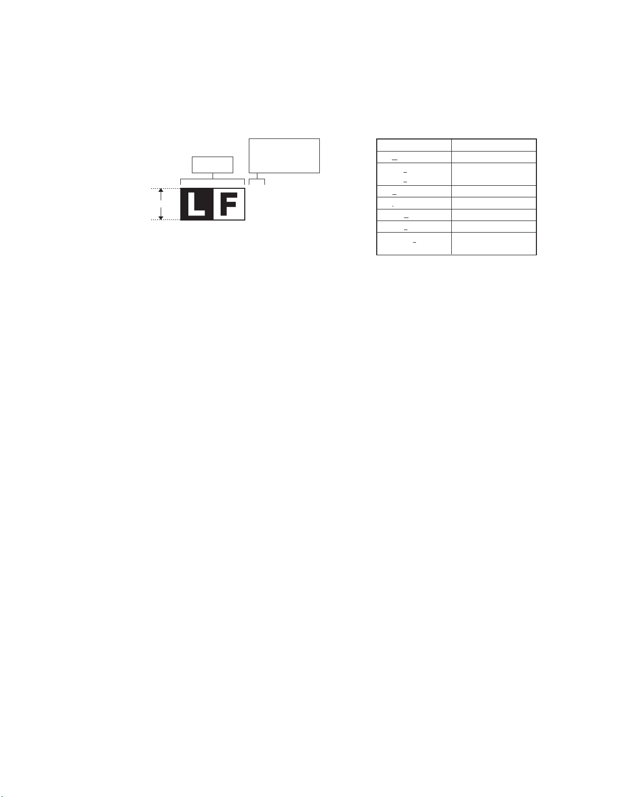
LEAD-FREE SOLDER
The PWB’s of this model employs lead-free solder. The “LF” marks indicated on the PWB’s and the Service Manual mean “Lead-Free” solder.
The alphabet following the LF mark shows the kind of lead-free solder.
Example:
<Solder composition code of lead-free solder>
Solder composition
Sn-Ag-Cu
Sn-Ag-Bi
Sn-Ag-Bi-Cu
Sn-Zn-Bi
Sn-In-Ag-Bi
Sn-Cu-Ni
Sn-Ag-Sb
Bi-Sn-Ag-P
Bi-Sn-Ag
5mm
Lead-Free
Solder composition
code (Refer to the
table at the right.)
a
(1) NOTE FOR THE USE OF LEAD-FREE SOLDER THREAD
When repairing a lead-free solder PWB, use lead-free solder thread.
Never use conventional lead solder thread, which may cause a breakdown or an accident.
Since the melting point of lead-free solder thread is about 40°C higher than that of conventional lead solder thread, the use of the exclusive-use
soldering iron is recommendable.
Solder composition code
a
b
z
i
n
s
p
(2) NOTE FOR SOLDERING WORK
Since the melting point of lead-free solder is about 220°C, which is about 40°C higher than that of conventional lead solder, and its soldering capacity is
inferior to conventional one, it is apt to keep the soldering iron in contact with the PWB for longer time. This may cause land separation or may exceed
the heat-resistive temperature of components. Use enough care to separate the soldering iron from the PWB when completion of soldering is
confirmed.
Since lead-free solder includes a greater quantity of tin, the iron tip may corrode easily. Turn ON/OFF the soldering iron power frequently.
If different-kind solder remains on the soldering iron tip, it is melted together with lead-free solder. To avoid this, clean the soldering iron tip after
completion of soldering work.
If the soldering iron tip is discolored black during soldering work, clean and file the tip with steel wool or a fine filer.
Page 71

CAUTION FOR BATTERY REPLACEMENT
(Danish) ADVARSEL !
Lithiumbatteri – Eksplosionsfare ved fejlagtig håndtering.
(English) Caution !
Danger of explosion if battery is incorrectly replaced.
Dispose of used batteries according to manufacturer’s instructions.
(Finnish) VAROITUS
Paristo voi räjähtää, jos se on virheellisesti asennettu.
Vaihda paristo ainoastaan laitevalmistajan suosittelemaan
(French) ATTENTION
Il y a danger d’explosion s’ il y a remplacement incorrect
de la batterie. Remplacer uniquement avec une batterie du
même type ou d’un type équivalent recommandé par
Mettre au rebut les batteries usagées conformément aux
(Swedish) VARNING
(German) Achtung
Explosionsgefahr bei Verwendung inkorrekter Batterien.
Als Ersatzbatterien dürfen nur Batterien vom gleichen Typ oder
vom Hersteller empfohlene Batterien verwendet werden.
Entsorgung der gebrauchten Batterien nur nach den vom
Udskiftning må kun ske med batteri
af samme fabrikat og type.
Levér det brugte batteri tilbage til leverandoren.
Replace only with the same or equivalent type
recommended by the manufacturer.
tyyppiin. Hävitä käytetty paristo valmistajan ohjeiden
mukaisesti.
le constructeur.
instructions du fabricant.
Explosionsfara vid felaktigt batteribyte.
Använd samma batterityp eller en ekvivalent
typ som rekommenderas av apparattillverkaren.
Kassera använt batteri enligt fabrikantens
instruktion.
Hersteller angegebenen Anweisungen.
CAUTION FOR BATTERY DISPOSAL
(For USA, CANADA)
THIS PRODUCT CONTAINS A LITHIUM PRIMARY
(MANGANESS DIOXIDE) MEMORY BACK-UP BATTERY
THAT MUST BE DISPOSED OF PROPERLY. REMOVE THE
BATTERY FROM THE PRODUCT AND CONTACT YOUR
LOCAL ENVIRONMENTAL AGENCIES FOR INFORMATION
ON RECYCLING AND DISPOSAL OPTIONS.
CE PRODUIT CONTIENT UNE PILE DE SAUVEGARDE DE
MÉMOIRE LITHIUM PRIMAIRE (DIOXYDE DE MANGANÈSE)
QUI DOIT ÊTRE TRAITÉE CORRECTEMENT. ENLEVEZ LA
PILE DU PRODUIT ET PRENEZ CONTACT AVEC VOTRE
AGENCE ENVIRONNEMENTALE LOCALE POUR DES
INFORMATIONS SUR LES MÉTHODES DE RECYCLAGE ET
"BATTERY DISPOSAL"
"TRAITEMENT DES PILES USAGÉES"
DE TRAITEMENT.
Page 72

COPYRIGHT © 2004 BY SHARP CORPORATION
All rights reserved.
Printed in Japan.
No part of this publication may be reproduced,
stored in a retrieval system, or transmitted,
in any form or by any means,
electronic; mechanical; photocopying; recording or otherwise
without prior written permission of the publisher.
Trademark acknowledgements
• Microsoft® Windows® operating system is a trademark or copyright of Microsoft
Corporation in the U.S.A. and other countries.
®
• Windows
and Windows
U.S.A. and other countries.
• IBM and PC/AT are trademarks of International Business Machines Corporation.
• Acrobat
reserved. Adobe, the Adobe logo, Acrobat, and the Acrobat logo are trademarks of
Adobe Systems Incorporated.
• All other trademarks and copyrights are the property of their respective owners.
95, Windows® 98, Windows® Me, Windows NT® 4.0, Windows® 2000,
®
XP are trademarks or copyrights of Microsoft Corporation in the
®
Reader Copyright® 1987- 2002 Adobe Systems Incorporated. All rights
SHARP CORPORATION
Digital Document System Group
Products Quality Assurance Department
Yamatokoriyama, Nara 639-1186, Japan
2004 February Printed in Japan
 Loading...