

Page 1

TopPage
DESTINATION F
Refer to "HFC-134a COOLING UNIT" Service Manual for handling this refrigerant.
Refrigerant; HFC-134a
SJPT56RHS
SERVICE MANUAL
No. S3120SE55CRNFT
Refrigerator-freezer
MODELS
SJ-PT56R SJ-T56R
CONTENTS
CHAPTER 1. SPECIFICATION
CHAPTER 2. DESIGNATION OF VARIOUS PARTS
[1] EXTERNAL DESCRIPTION........................... 2-1
[2] CONSTRUCTIONS ........................................ 2-3
CHAPTER 3. DIMENSIONS
[1] OUTER DIMENSIONS AND CLEARANCE........ 3-1
[2] INNER DIMENSIONS .................................... 3-2
CHAPTER 4. LIST OF ELECTRICAL PARTS
[1] SJ-PT56R....................................................... 4-1
[2] SJ-T52R/T56R ............................................... 4-1
CHAPTER 5. WIRING DIAGRAM
[1] WIRING DIAGRAM ........................................ 5-1
[2] ELECTRIC ACCESSORIES LAYOUT ........... 5-2
[3] CIRCUIT DIAGRAM....................................... 5-4
CHAPTER 6. FAILURE DIAGNOSIS
[1] OUTLINE OF CONTROL............................... 6-1
[2] WHEN THE DEFROSTING FAILURE IS
DOUBTFUL(Only for SJ-PT56R) ................... 6-1
[3] RE-SETTING OF MICROCOMPUTER AT
POWER FAILURE.......................................... 6-1
[4] DIAGNOSIS METHOD OF FAILURE
AROUND PWB .............................................. 6-2
[5] CONVERSION TABLE BETWEEN TEM-
PERATURE AND RESISTANCE VALUE........ 6-3
SJ-PT56R-HS
SJ-T52R-S
SJ-T56R-S
CHAPTER 7. SELF-DIAGNOSIS MODE
(Only for SJ-PT56R)
CHAPTER 8. MODE FOR DIS PLAY
(Only for SJ-PT56R)
CHAPTER 9. ASSEMBLING PROCEDURES OF
MAIN PARTS AND CAUTIONS
[1] FAN LOUVER AND
E.V COVER ASSEMBLY ...............................9-1
[2] R CONTOROL COVER ASSEMBLY
(SJ-PT56R)................................................... 9-3
[3] R CONTOROL COVER ASSEMBLY
(SJ-T52R/T56R) ...........................................9-5
[4] R SHOWER DUCT ASSEMBLY....................9-7
[5] DEFROST HEATER ASSEMBLY..................9-8
CHAPTER 10. COOLING UNIT
[1] COOLING UNIT...........................................10-1
[2] LOCATION ..................................................10-2
Parts Guide
This document has been published to be used for
after sales service only.
The contents are subject to change without notice.
Page 2

SJPT56RHS
1 – 1
SJPT56RHS
Service Manual
CHAPTER 1. SPECIFICATION
Items SJ-T52R SJ-PT56R SJ-T56R
Type 2-Door
Outer dimensions Height 1670mm(65.7") 1770mm(69.7")
Width 800mm(31.5") 800mm(31.5")
Depth 720mm(28.3") 720mm(28.3")
Rated storage volume
(Rated volume)
Total 514liter(18.1cu.ft) 555liter(19.6cu.ft)
Freezer 139liter(4.8cu.ft) 139liter(4.9cu.ft)
Refrigerator 375liter(13.3cu.ft) 416liter(14.7cu.ft)
Defrosting System Heater system
Start Automatic
Finish Automatic
Temperature control Automatic (Adjustable)
No-frost freezer Yes
Interior lamp Freezer — 1 (LED) —
Refrigerator 1 1 (LED) 1
Evaporating pan 1 (unremovable)
Freezer Compartment F-shelf 1
F-shelf S — 1 —
Ice cube maker Twin ice cube maker
Ice storage box 1
F door pocket ass'y 1
RF door pocket 1
Refrigerator Compartment Fresh case 1
Fresh door 1
R glass shelf ass'y 2 1 2
R glass shelf SF ass'y — 1 —
R glass shelf SB ass'y — 1 —
V glass shelf ass'y 1
Vegetable case 2
Egg tray 1 2 1
R door pocket 1
R door cover — 1 —
RF door pocket 1
Utility pocket 2
Utility pocket L — 1
Bottle pocket 1
Tube stand 1 2 1
Deodorizing unit (Honeycomb type) 1 2 1
Door opening side — Changeable*1 —
*1 To modify the door, REFRIGERATOR HINGE KITS (SJ-L55CRD) will be required.
All modification work should be carried out by a competent person.
RATING
Items SJ-T52R SJ-PT56R SJ-T56R
Rated voltage (V~) 110
Rated frequency (Hz) 60
Climate class ST
Rated input (W) 100
Rated input of heating systems (W) 146
Defrosting input (W) 146
Refrigerant (Charging quantity) [Non-flammable] HFC-134a(110g) HFC-134a(110g) HFC-134a(110g)
Insulation blowing gas [Flammable] Cyclo pentane (HC)
Net Weight (kg) 77 82 79
PLUG TYPE
Plug cord 2 pin
Plug type A-1
Destination mark F
COLOR
Items -HS/S
Outside color Silver
Inside color White
Page 3
SJPT56RHS
2 – 1
SJPT56RHS
Service Manual
CHAPTER 2. DESIGNATION OF VARIOUS PARTS
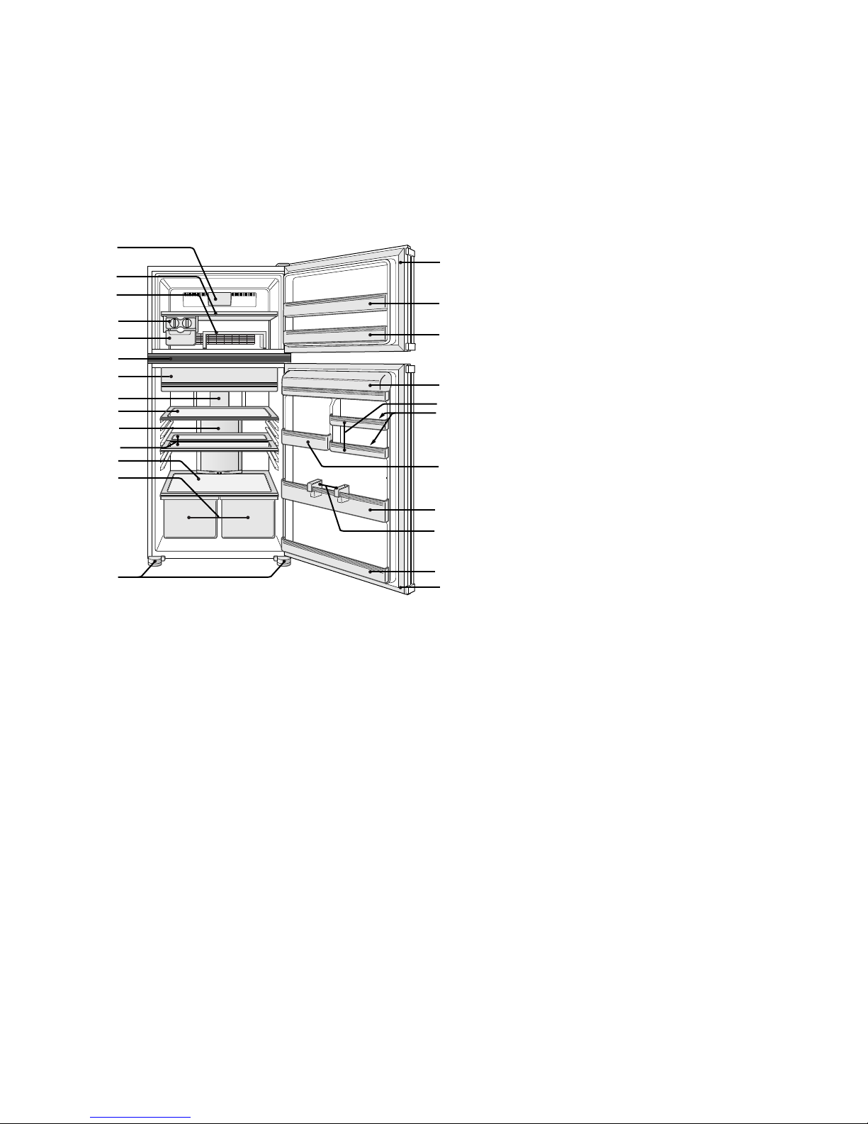
[1] EXTERNAL DESCRIPTION
The names in parenthesis “[ ]” are the denominations used in the REPLACEMENT PARTS LIST.
1. SJ-PT56R
1. Freezer LED light [LED lamp]
2. Freezer shelf [F-shelf]
3. Movable shelf [F-shelf s]
4. Ice cube maker
5. Ice cube box [Ice storage box]
6. Control panel
7. Fresh case & door
8. Refrigerator LED light [LED Lamp]
9. Refrigerator shelf [R glass shelf ass'y]
10. Hybrid cooling panel (Aluminum panel)
11. Half shelf (1 pair)
[R galss shelf sf ass'y,
R glass shelf sb ass'y]
12. Fruit and vegetable shelf
[V glass shelf ass'y]
13. Fruit and vegetable crisper
[Vegetable case]
14. Adjustable feet & cover [Adjustable leg]
15. Magnetic door seal [Door packing]
16. Flexible pocket [F door pocket ass'y]
17. Door pocket [RF door pocket]
18. Refrigerator pocket & cover
19. Utility pocket
20. Egg holder [Egg tray]
21. Utility pocket (large)
22. Bottle pocket
23. Tube stand
1
2
3
4
5
6
7
8
9
10
11
12
13
14
15
16
17
18
19
20
21
23
22
17
15
Page 4
SJPT56RHS
2 – 2
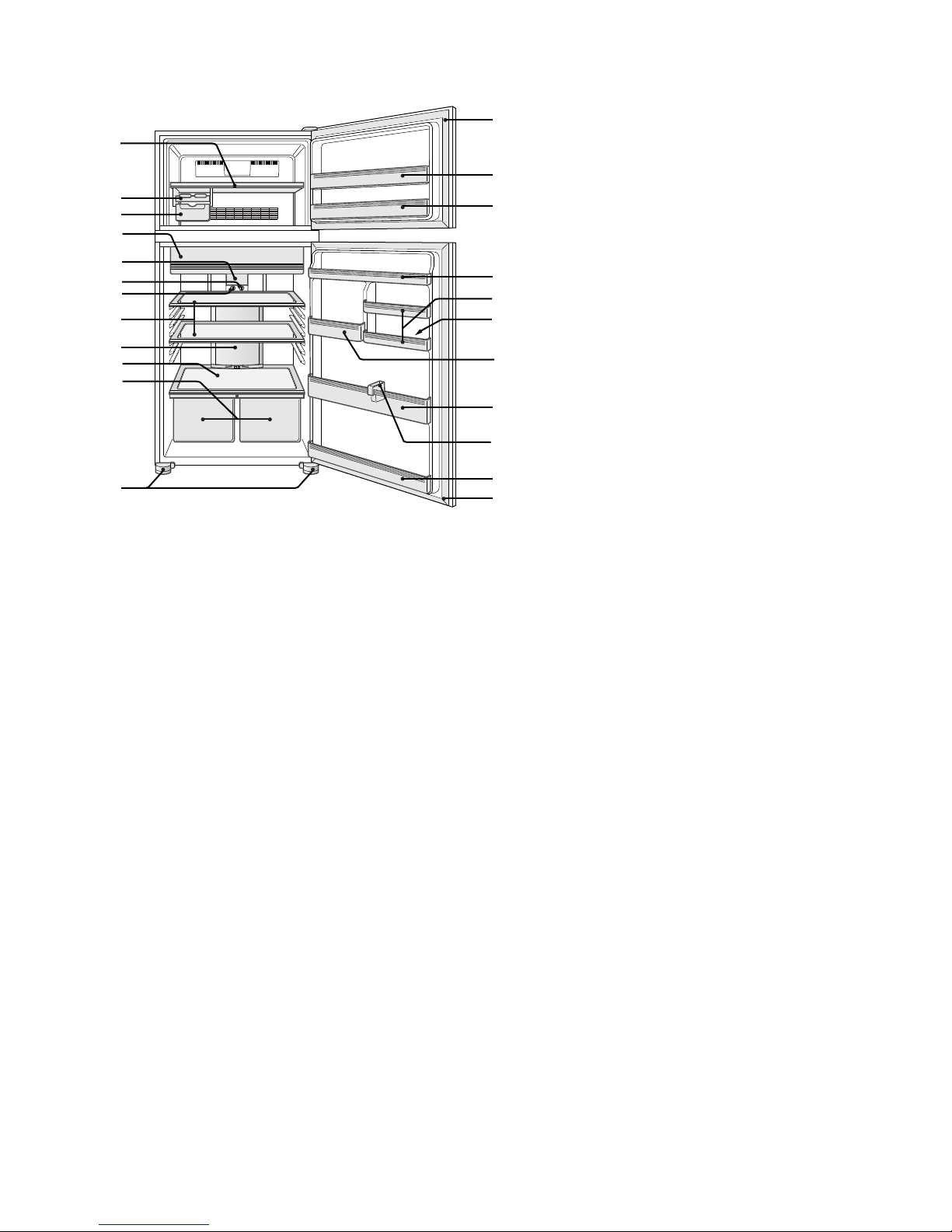
2. SJ-T52R,T56R
1. Freezer shelf [F-shelf]
2. Ice cube maker
3. Ice cube box [Ice storage box]
4. Fresh case & door
5. Refrigerator light [Lamp]
6. Freezer temp.conrol knob
7. Refrigerator temp.control knob
8. Refrigerator shelf [R glass shelf ass'y]
9. Hybrid cooling panel (Aluminum panel)
10. Fruit and vegetable shelf
[V glass shelf ass'y]
11. Fruit and vegetable crisper
[Vegetable case]
12. Adjustable feet & cover [Adjustable leg]
13. Magnetic door seal [Door packing]
14. Flexible pocket [F door pocket ass'y]
15. Door pocket [RF door pocket]
16. Refrigerator pocket
17. Utility pocket
18. Egg holder [Egg tray]
19. Utility pocket (large)
(Only for SJ-T56R)
20. Bottle pocket
21. Tube stand
17
18
13
15
16
12
1
2
3
4
5
8
9
10
11
6
7
13
14
15
19
20
21
Page 5
SJPT56RHS
2 – 3
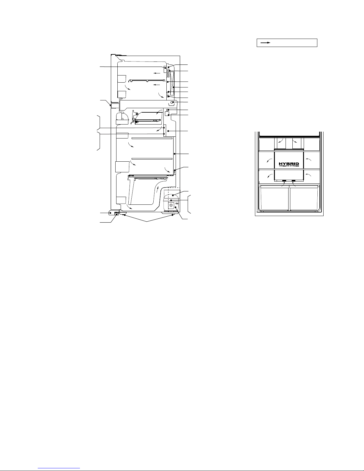
[2] CONSTRUCTIONS
Evaporator
Damper ass'y
Freezer
compartment
Refrigerator
compartment
Defrost heater
R-thermistor
Aluminum panel
F-thermistor
DEF-thermistor
Deodorizer
Deodorizer
F fan motor
Fuse ass'y
Ionizer-K
LED PWB ass'y
(Only for SJ-T52R/T56R)
(for SJ-T52R/T56R)
(Only for SJ-PT56R)
(Only for SJ-PT56R)
(Only for SJ-PT56R)
(for SJ-PT56R)
Mark : Cold air flow
Main PWB ass'y
Caster
Foot cover
Evaporating pan
Refrigerator temp. control knob
Lamp
LED lamp PWB L ass'y
R LED lamp PWB L ass'y
Freezer temp. control knob
Adjustable leg ass'y
Compressor
Starting relay
Overload relay(Protector)
Page 6
SJPT56RHS
3 – 1
SJPT56RHS
Service Manual
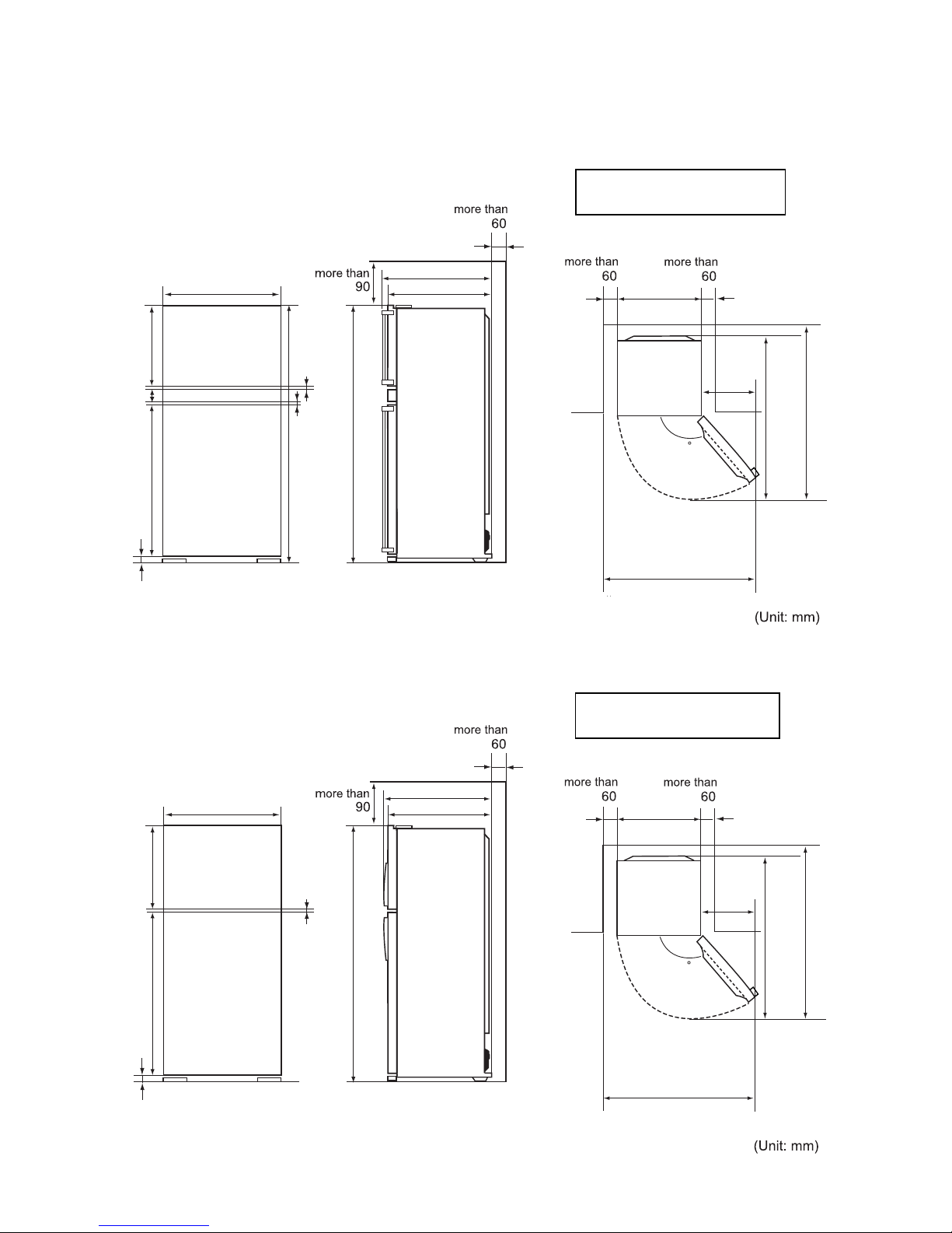
CHAPTER 3. DIMENSIONS
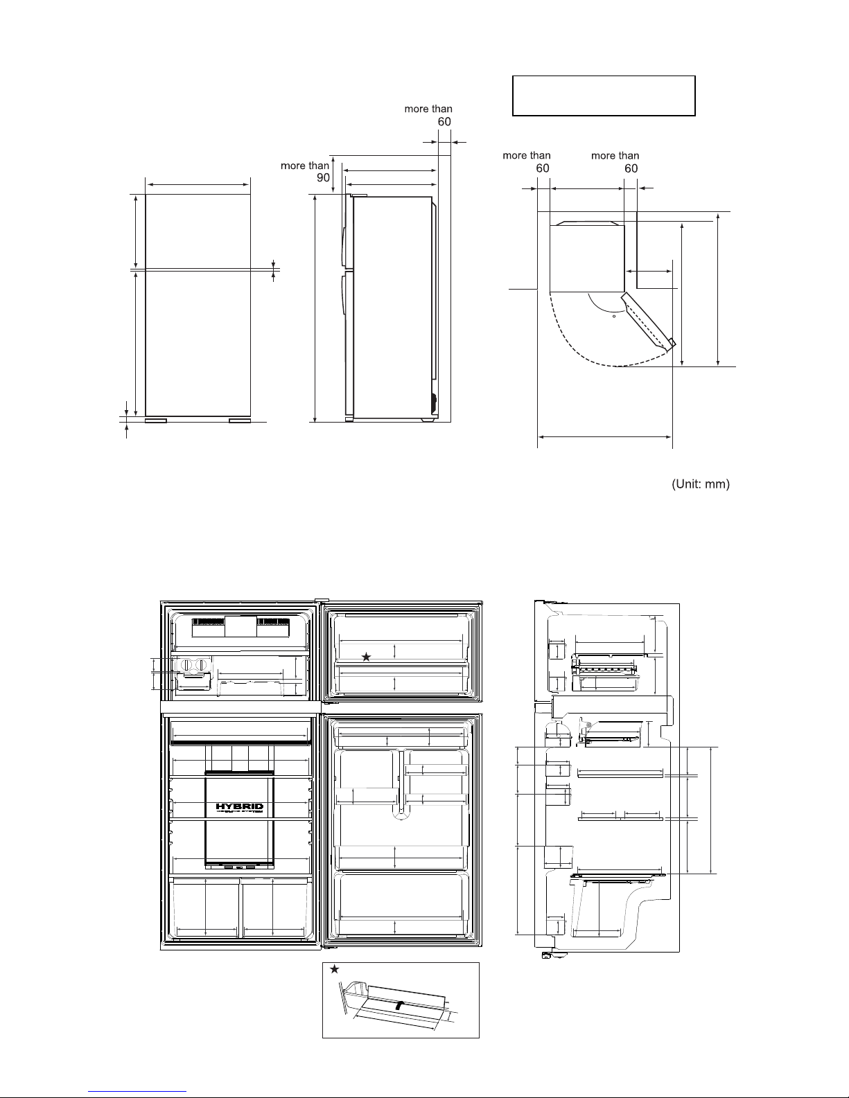
[1] OUTER DIMENSIONS AND CLEARANCE
1. SJ-PT56R
2. SJ-T52R
800
10
720
728
1150
49944
60
1770
7
This model is Free standing type.
(Not built-in type.)
800
1400
540
135
1500
1440
800
10
720
725
1076
524
60
1670
This model is Free standing type.
(Not built-in type.)
800
1400
540
135
1500
1440
Page 7
SJPT56RHS
3 – 2
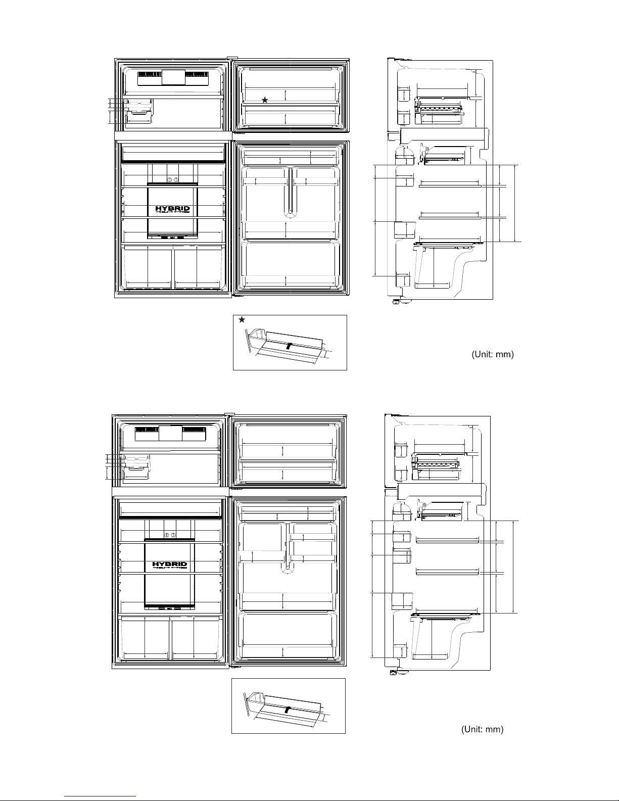
3. SJ-T56R
[2] INNER DIMENSIONS
The dimensions between shelves can be changed by setting the shelves on the other rails.
1. SJ-PT56R
This model is Free standing type.
(Not built-in type.)
800
10
720
725
1176
524
60
1770
800
1400
540
135
1500
1440
65
82
135
640
326
63
128
660
74
660
74
665
45
10
328
53
328
53
330
83
660
17
660
74
635
653
653
275 275
265
265
320
250
85
82
268
74
85
74
195208
265
122
53
122
120
120
45
89
83
142257360
132
17
98
72
150 150
356
345
165203
625
210
235
265
648
50
330
Page 8
SJPT56RHS
3 – 3
2. SJ-T52R
3. SJ-T56R
82
135
640
660
74
660
74
665
45
10
328
53
328
53
653
653
635
648
275 275
265
265
660
74
660
17
50
330
30 47
320
250
85
82
268
74
85
74
122
528
265
122
122
120
345
345
356
165208155
132
17
98
72
235
265
89246244
45
53
195208
82
135
640
660
74
660
74
665
45
110
328
53
328
53
330
83
660
117
660
74
635
653
653
275 275
265
265
320
250
85
82
268
74
85
74
195208
265
122
53
122
120
120
45
89
83
142257360
132
117
98
72
356
345
345
165203
625
210
235
265
648
50
330
ڎ
ڎ
30 47
Page 9
SJPT56RHS
4 – 1
SJPT56RHS
Service Manual
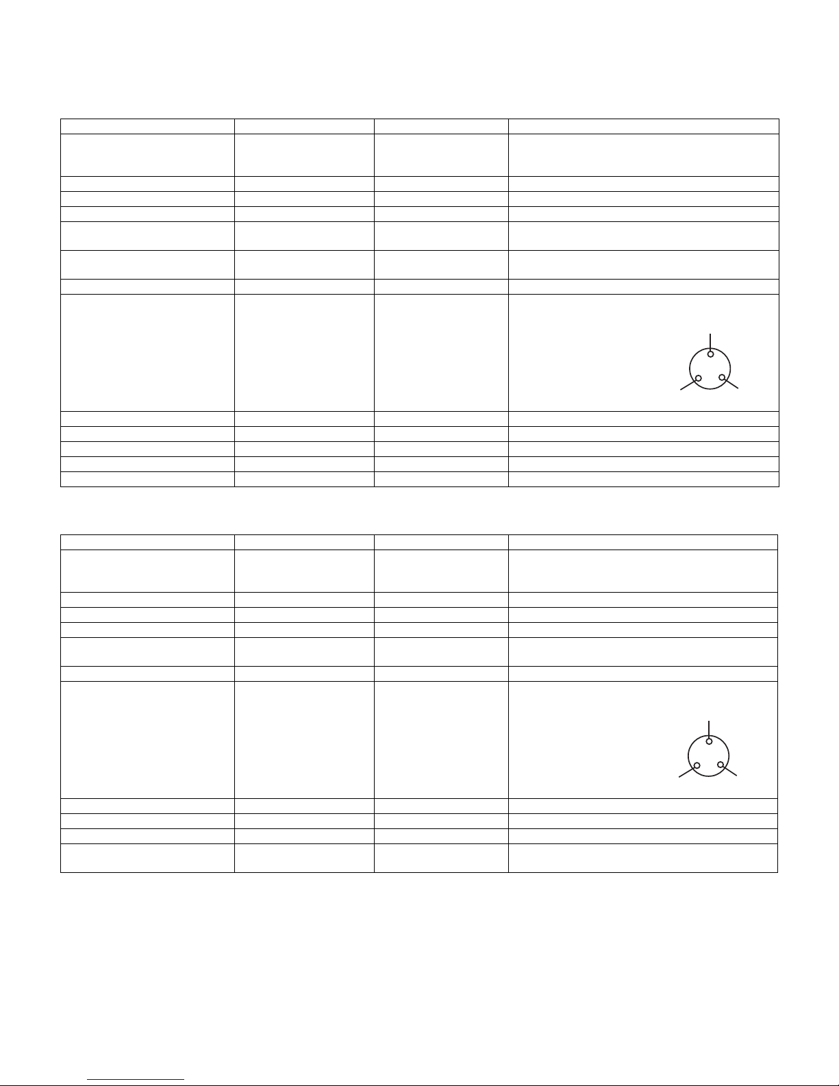
CHAPTER 4. LIST OF ELECTRICAL PARTS
[1] SJ-PT56R
[2] SJ-T52R/T56R
ITEMS TYPE NAME RATING SPECIFICATIONS
R Thermistor
F Thermistor
Defrost Thermistor
—
—
—
DC 5V
DC 5V
DC 5V
R0 = 6.4 k, B(0) = 3811
R0 = 6.4 k, B(0) = 3811
R0 = 15 k, B(0) = 3811
Thermo. fuse 12Y 250V 2A Working temp. : 76 C
Defrost heater — 110-120V 77.7 160W at 115V
Fan motor FBA12J15VXD DC 15V —
F Door switch
R Door switch
D3D-211
D3D-211
250V 0.5A/125V 1A
250V 0.5A/125V 1A
3 Terminals lever type
3 Terminals lever type
F Lamp (LED)
R Lamp (LED)
DPWB-A135CBKZ
DPWB-A150CBKZ
DC 14.5V
DC 14.5V
75mA, white LED Lamp
125mA, white LED Lamp
LED Operation FPWB-A499CBKZ DC 14.5V Blue LED
Compressor EGX60HLC 115-127V/60Hz Cooling capacity : 179W (50Hz)
Main coil : 5.10
Aux. coil : 5.70
(at 25 C)
PTC Relay PTH7M4R7MD3 50/60 Hz 4.7 0.94 (at 25 C)
Overload Relay(Protector) 4TM319NFBYY-53 — Open/ Close : 120/ 61 C
Capacitor RC-EZA198CBZZ — 250V, 12F
Main PWB FPWB-A511CBKZ 100-127V Control by MPU
Ionizer-K(Plasmacluster unit) FTRN-A014CBKZ DC 12V —
ITEMS TYPE NAME RATING SPECIFICATIONS
R Thermistor
F Thermistor
Defrost Thermistor
—
—
—
DC 5V
DC 5V
DC 5V
R0 = 6.4 k, B(0) = 3811
R0 = 6.4 k, B(0) = 3811
R0 = 15 k, B(0) = 3811
Thermo. fuse 12Y 250V 2A Working temp. : 76 C
Defrost heater — 110-120V 77.7 160W at 115V
Fan motor FBA12J15VXD DC 15V —
F Door switch
R Door switch
D3D-211
D3D-211
250V 0.5A/125V 1A
250V 0.5A/125V 1A
3 Terminals lever type
3 Terminals lever type
R Lamp — 120V 15W #187 Straight Terminal, Pitch 6
Compressor EGX60HLC 115-127V/60Hz Cooling capacity : 179W (50Hz)
Main coil : 5.10
Aux. coil : 5.70
(at 25 C)
PTC Relay PTH7M4R7MD3 50/60 Hz 4.7 0.94 (at 25 C)
Overload Relay(Protector) 4TM319NFBYY-53 — Open/ Close : 120/ 61 C
Capacitor RC-EZA198CBZZ — 250V, 12F
Main PWB
VR PWB
FPWB-A513CBKZ
FPWB-A554CBKZ
100-127V
DC 5V
Control by MPU
—
Common
Aux. coil
Main coil
Common
Aux. coil
Main coil
Page 10
SJPT56RHS
5 – 1
SJPT56RHS
Service Manual
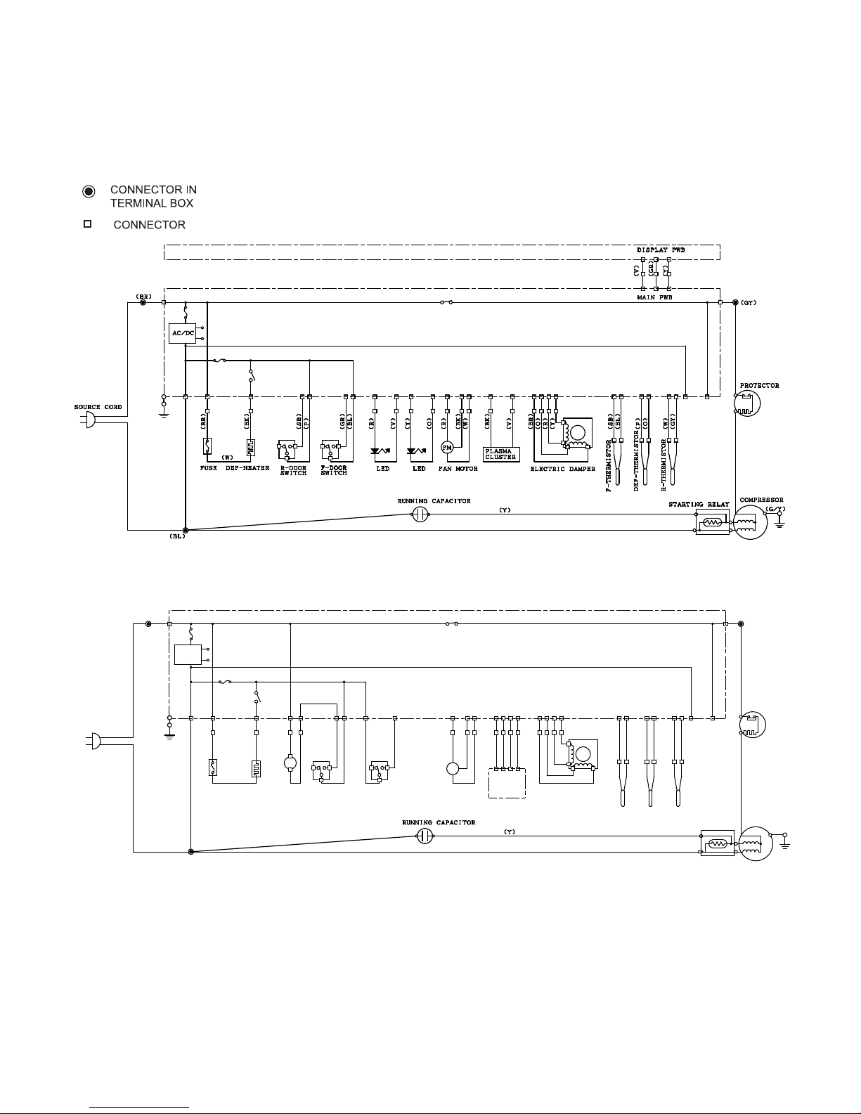
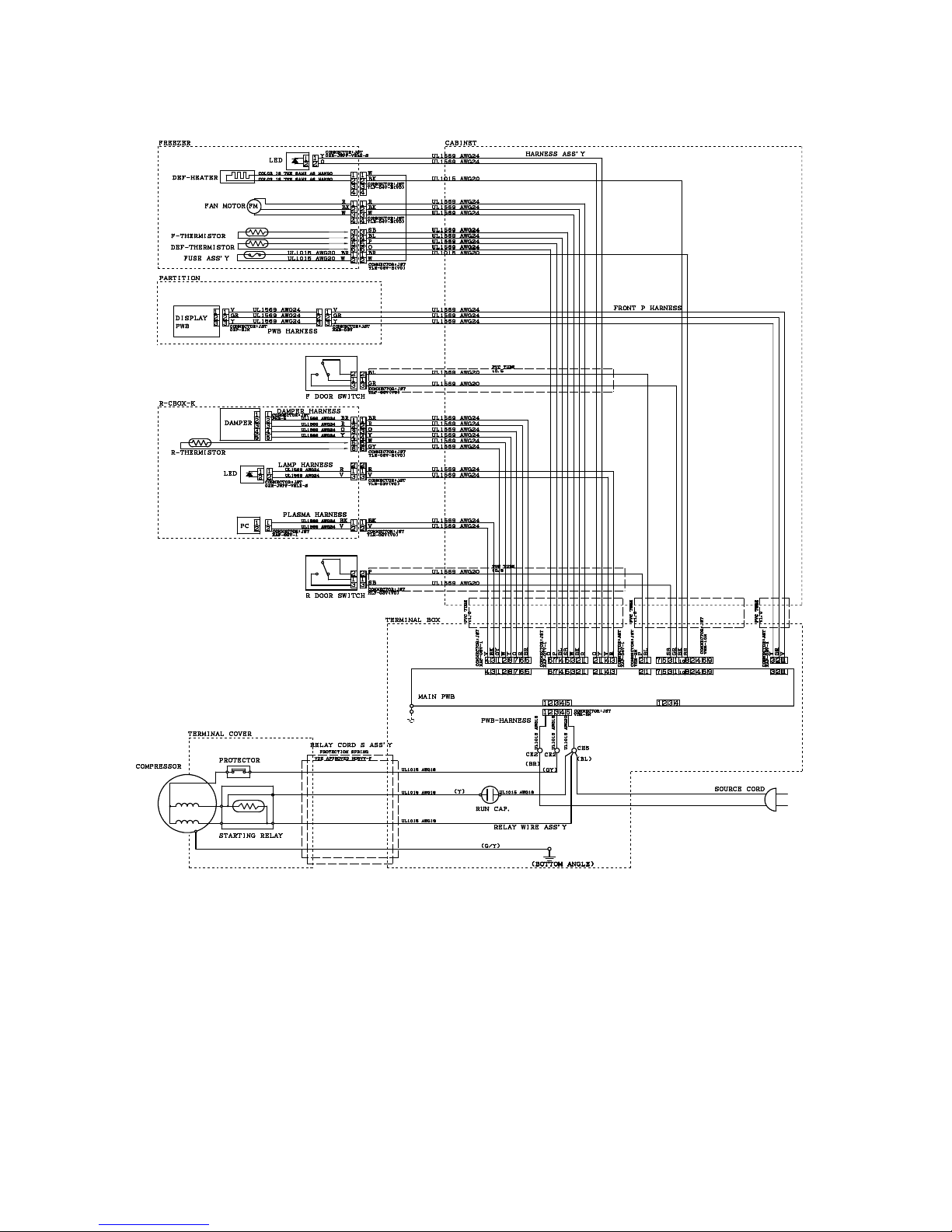
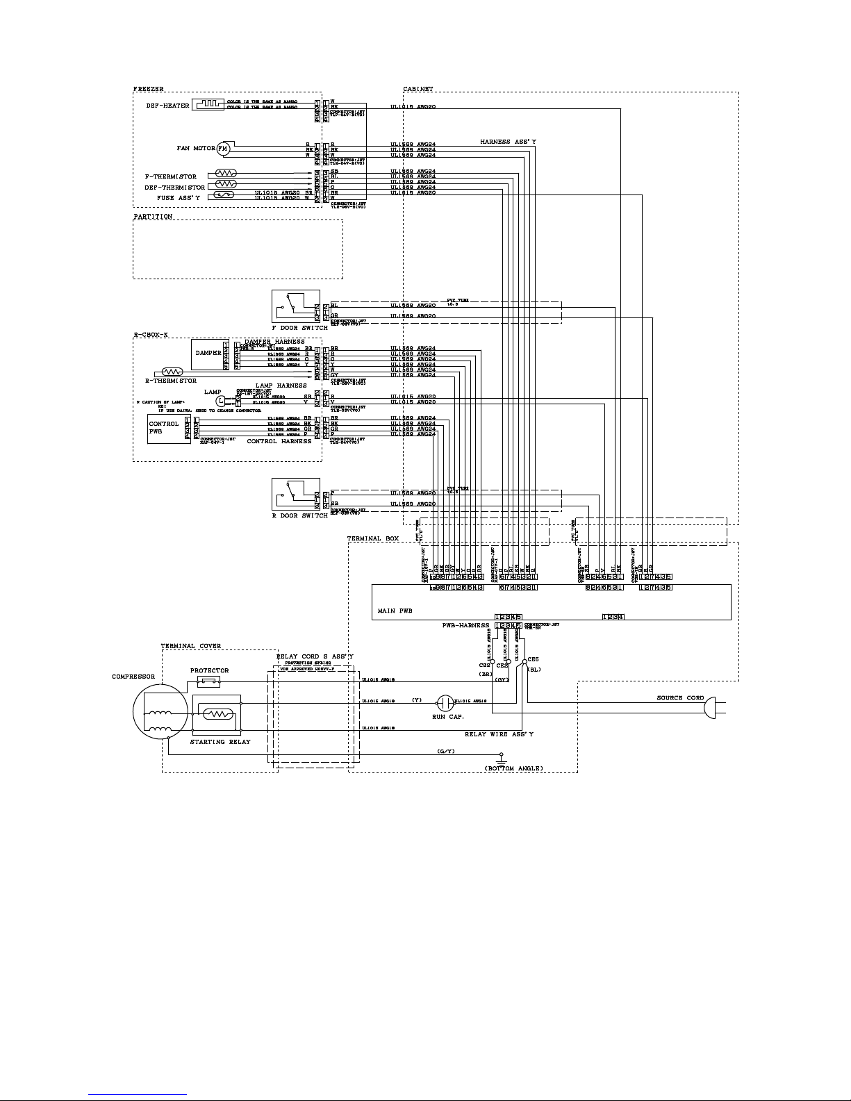
CHAPTER 5. WIRING DIAGRAM
[1] WIRING DIAGRAM
Be sure to replace the electrical parts with specified ones for maintaining the safety and performance of the set.
1. SJ-PT56R
2. SJ-T52R/T56R
STARTING RELAY
COMPRESSOR
(G/Y)
FUSE
DEF-HEATER
LAMP
R-DOOR
SWITCH
F-DOOR
SWITCH
FAN MO TOR
(BL)
(SOURCE CORD)
(BR)
AC/DC
MAIN PWB
(GY)
PROTECTOR
(BR)
(W)
(BK)
(V)
(SB)
L
(SB)
(P)
(BL)
(GR)
(R)
FM
(BK)
(W)
(BR)
(BK)
(GR)
(P)
CONTROL
PWB
(BR)
(O)
(R)
(Y)
ELECTRICAL DAMPER
(SB)
(BL)
(P)
(O)
(W)
(GY)
(F-THERMISTOR)
(DEF-THERMISTOR)
(R-THERMISTOR)
BK : BLACK
BR : BROWN
R : RED
O : ORANGE
Y : YELLOW
GR : GREEN
BL : BLUE
V : VIOLET
GY : GRAY
W : WHITE
P : PINK
SB : SKY-BLUE
G/Y : GREEN/YELLOW STRIPE
Page 11
SJPT56RHS
5 – 2
[2] ELECTRIC ACCESSORIES LAYOUT
1. SJ-PT56R
BK : BLACK
BR : BROWN
R : RED
O : ORANGE
Y : YELLOW
GR : GREEN
BL : BLUE
V : VIOLET
GY : GRAY
W : WHITE
P : PINK
SB : SKY-BLUE
G/Y : GREEN/YELLOW STRIPE
Page 12
SJPT56RHS
5 – 3
2. SJ-T52R/T56R
BK : BLACK
BR : BROWN
R : RED
O : ORANGE
Y : YELLOW
GR : GREEN
BL : BLUE
V : VIOLET
GY : GRAY
W : WHITE
P : PINK
SB : SKY-BLUE
G/Y : GREEN/YELLOW STRIPE
Page 13
SJPT56RHS
5 – 4
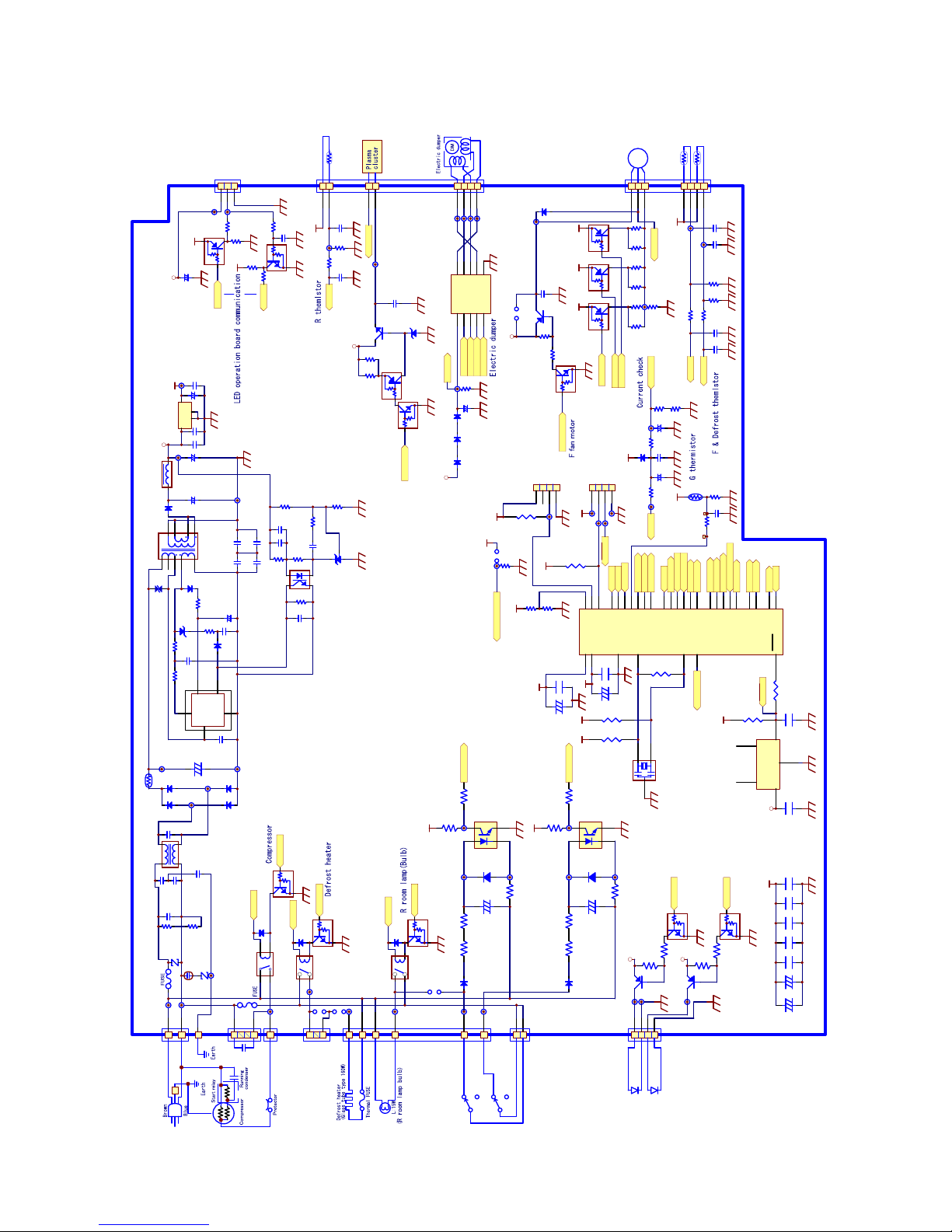
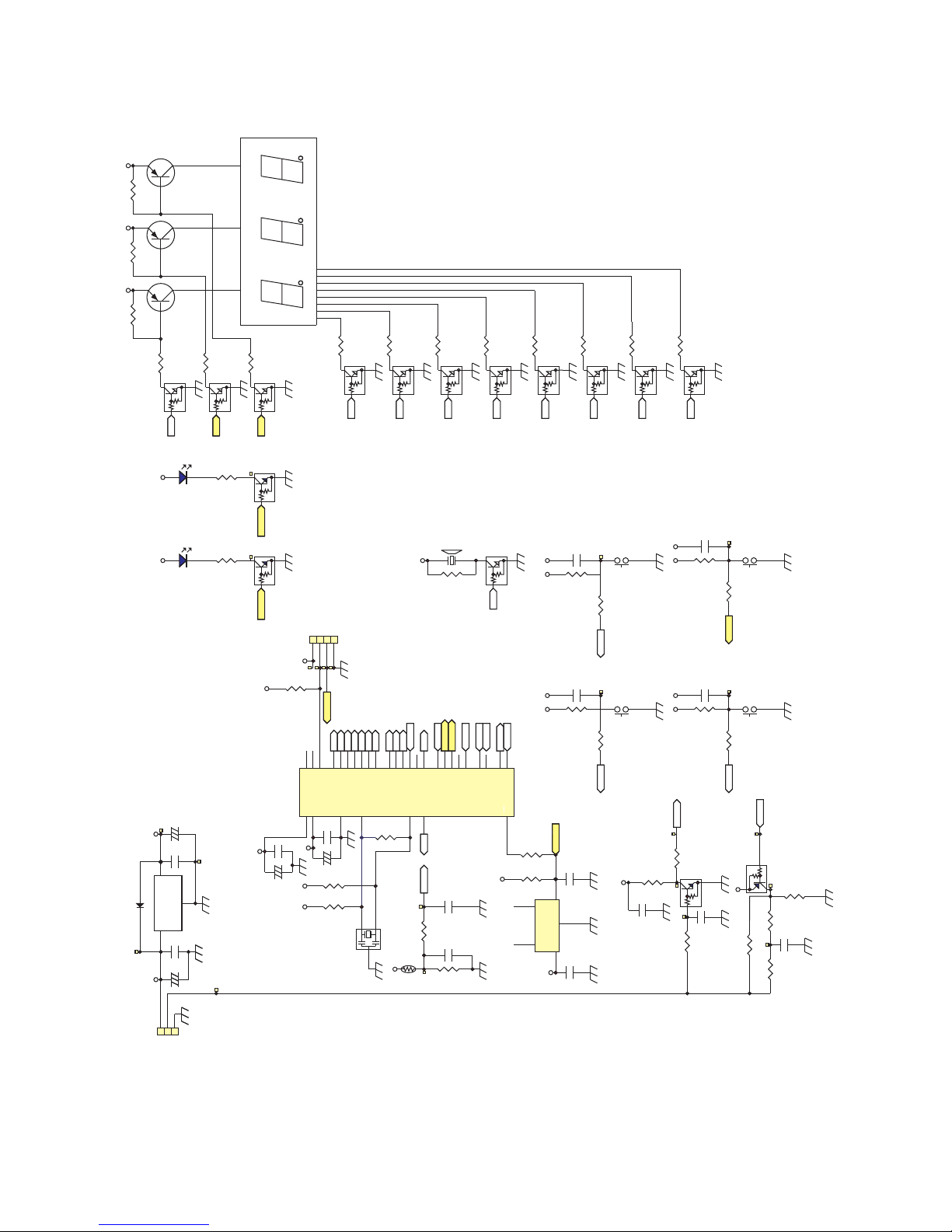
[3] CIRCUIT DIAGRAM
1. Main PWB (SJ-PT56R)
DC5V
AC160-288V
VM14.5V
1
2
4
3
RY2
FTR-F3(3 A)
1
3
5
Vin
G
Vou t
4
G
IC4
BP5225
C13
0.1u 25V
C15
0.1u/25V
D8
1N4005SG
(C73)
10000pF
(C75)
10000pF
R11
R14
R9
R7
1000p/50V
C16
1
2
34
PC1
PC123Y52
8.66kF
R8
C18
0.1u/50V
1k
20kF
1.8k
1.8kF
IC3
TA76431S
+
C14
100uF/10V
+
C74
1000uF/25V
D3
D1NL20U
D2
D1NL20U
R6
220pF/50V
Jumper
13kF
C9
C10
ZD1
HZ11C1
D4
D2S6M
R5R34
2200p/50V
C8
16kF
150pF/2kV
+
C11
100uF/25V
910k(1/2W)
(AX)
+
C7
R1
150u/450V
F1
2.5A/250V
VRS1
TNR10V471K
C1
L1
SS21V-050360(36mH)
C2
0.1u/275V
0.1u/275V
C21
0.1u
C20
0.1u
VDD
2
GND
3
VOUT
1
N.C.
4
N.C.
5
IC9
BD4842G
C19
0.01u
+5V
R83
10k
R93
1k
R86
1M
2
1
3
CF1
CST LS8M00G56-A0
RXD
P0032P0131P0230P0329P0428P0527P06
26
AN0
25
P3424P33
23
P1022P11
21
VREF
20
P1219P13
18
TXD0
17
P35
1
TXD1
2
RESET
3
XOUT
4
AVS S5XIN
6
AVC C
7
MODE
8
RXD1
9
P17
10
P3611P31
12
P5413P53
14
P16
15
RXD0
16
IC1
R5F21266SNFP
TXD
C23
0.1u
+C22
100u/25V
+(C24)
100u/25V
(RD)
(RD)
(R87)
10k
(R88)
10k
132
4
CN11
B4B-PH-KL
RESET
RESET
R89
10k
1
3
(CN4)
B2P3-VH
1
4
(CN3)
B2P4-VH-BL (LF)(SN)
123
CN8
B03B-XASK-1-A(LF)(SN)
1
CN10A
B7B-XASK-1-A(LF)(SN)
2
CN10B
B7B-XASK-1-A(LF)(SN)
3
CN10C
B7B-XASK-1-A(LF)(SN)
4
CN10D
B7B-XASK-1-A(LF)(SN)
5
CN10E
B7B-XASK-1-A(LF)(SN)
6
CN10F
B7B-XASK-1-A(LF)(SN)
7
CN10G
B7B-XASK-1-A(LF)(SN)
1
CN9A
B8B-XASK-1-A(LF)(SN)
2
CN9B
B8B-XASK-1-A(LF)(SN)
3
CN9C
B8B-XASK-1-A(LF)(SN)
4
CN9D
B8B-XASK-1-A(LF)(SN)
5
CN9E
B8B-XASK-1-A(LF)(SN)
6
CN9F
B8B-XASK-1-A(LF)(SN)
7
CN9G
B8B-XASK-1-A(LF)(SN)
8
CN9H
B8B-XASK-1-A(LF)(SN)
70m A /12V
F-TH
DEF-TH
R-TH
F-TH
DEF-TH
R58
C56 C57
0.1uF/ 25V 0.1uF/ 25V
R56 4.7k
R57 4.7k
16.9kF
R59
16.9kF
(C54)
0.01u
(C55)
0.01u
/50V
/50V
R-TH
R30
C37
0.1uF/ 25V
R29
4.7k
6.34kF
(C36)
0.01u
/50V
(R61)(R60)
R53
F_FA N_H
F-FM
F_FA N_L
VM14.5V
R48
F_FA N_ON
C50
R47
0.1uF/ 25V
4.7k
750(1/2W)
6.19kF
10kF
3.16kF
Q14
KTA1273-Y
Q15
KRC101S
(Q17)
KRA101S
Q16
KRA101S
I_detect
FFanmotor
VM14.5V
+
C42
100uF/25V
OUT110OUT29OUT38OUT4
7
IN12IN23IN34IN4
5
GND
6
VCC
1
IC6
LB1948M
D5
1N4005SG
DUMP_B1
DUMP_B2
DUMP_A1
DUMP_A2
D6
1N4005SG
D7
1N4005SG
PLASMA
Q7
KTC3205
ZD2
HZ12B2
VM14.5V
R32
C38
0.1uF/25V
470
Q8
KRA101S
Q9
KRC101S
I_detect
R31
470
910k(1/2W)
(AX)
R2
D16
1SR139-600
D17
D18
D19
F2
250V4A
1
2
3
D12
1SS133
D10
1SS133
Q2
KRC101S
Q3
DTD123ES
DEF_H
Comp
R16
43k
(1/2W)
(AX)
R15
43k
(1/2W)
(AX)
R26
4.7k
(1/10W)
D13
1SS133
132
4
PC2
PC123Y52
R12
4.7k
(1/10W)
R19
4.7k (1/10W)
+
C25
10uF/ 50V
1
2
3
RDoorSW
(R81)
10k
E8EmulatorConnector
Vcc
Mode
Reset
Vss
F Roomlamp
LED
TP13
(L3)
+
C12
100uF/25V
C31
TXD
RXD
DC5V
DC5V
R18
R17
R21
1k
R22
1k
2.7k
2.7k
Q5
KRA101S
Q6
KRC101S
TP1
Toroidal Core(ESD-R-3810Turns)
RDOORSW
FDOORSW
TP2
TP44
ForIsraelonly
TP11
RY1
FTR-H2AL
TP43
TP14 TP15
TP16
TP17
TP12
TP46
TP47
TP48
TP49
Film
Film
TP45
TP7
TP6
C76
10000pF
C77
10000pF
250V
TP9
TP8
TP18
TP20
VM14.5V
R20
1k
0.01u
TP25
TP28
TP29
TP30
TP31
TP19
TP36
TP37
TP41
TP40
I_me s
R46
DC5V
R44
R45
0.51
1k
R55
1W
1W
4.7k
D11
1SS133T
(AX)
(AX)
+
C78
1uF/50V
+
C49
100uF/10V
0.51
(C48)
0.1u
I_detect
(JMP 2)
OPEN
DC5V
R82
10k
TP26
C67
0.1u
+
C64
100u/25V
C66
0.1u
+C65
100u/25V
C69
0.1u
C68
0.1u
C70
0.1u
DC5V
DEF_H
Comp
I_me s
R-TH
DUMP_B1
DUMP_B2
DUMP_A1
DUMP_A2
F_FA N_H
F_FA N_L
F_FA N_ON
F-TH
DEF-TH
Ma in Control Board Ci rcuit Diagram
1.Ratingof reslstors without appointment are 1/10W, error 5%(J).
2.Ratingof capacitors without appointmentare 0.01u/50V,0.1u/50V.
3.Partswithparenthesesare not in use,but canbe inserted.
ZD3
STO3D-200
1SR139-600
1SR139-600
1SR139-600
TP35
TP34
(C17)
0.1u
TSL11 12RA-100M3R7-PF
Plasmacluster
PLASMA
HALL
GND
COIL
DC5VDC5V
DC5V
DC5V
DC5V
DC5V
DC5V DC5V
DC5V
DC5V
DC5V
DC5V
DC5V
65432
11108
9
TRNS1
EER28/5.95mH
Q10
2SB1237
R27
1k
R28
4.7k
Q1
KRC101S
F_Lam p
VM14.5V
+
(C79)
100uF/25V
(C27)
0.1u
GND
3
F/B
2
Vcc
4
Z/C
1
D
5
IC2
MR1712
1
CN1A
B3P(5-2,4)-VH(LF)(SN)
3
CN1B
B3P(5-2,4)-VH(LF)(SN)
5
CN1C
B3P(5-2,4)-VH(LF)(SN)
C4
SA1
RA-272M-C 6-F
C6
C5
4700pF
4700pF
4700pF
/250VAC
VRS2
TNR10V511K
1
Tab1 TP42098-21
TP3
1
CN5A
B6P(10-2,4,6,9)-VH(LF)(SN)
3
CN5B
B6P(10-2,4,6,9)-VH(LF)(SN)
5
CN5C
B6P(10-2,4,6,9)-VH(LF)(SN)
7
CN5D
B6P(10-2,4,6,9)-VH(LF)(SN)
8
CN5E
B6P(10-2,4,6,9)-VH(LF)(SN)
10
CN5F
B6P(10-2,4,6,9)-VH(LF)(SN)
J3
JumperJ3Jumper
1
2
4
3
(RY3)
FTR-F3(3 A)
(D15)
1SS133
(Q19)
KRC101S
R_Lamp
TP38
D9
1N4005SG
R10
43k
(1/2W)
(AX)
R14
43k
(1/2W)
(AX)
R23
4.7k
(1/10W)
D14
1SS133
1
3
2
4
PC3
PC123Y52
R24
4.7k
(1/10W)
R25
4.7k (1/10W)
+
C26
10uF/ 50V
F DoorSW
TP22
TP23 TP24
DC5V
1
2
CN2B2P2-VH(LF) (SN)
TP4
JMP1
Jumper
TP39
RDoorSWinput
FDoorSWinput
FRoomLamp(LED)
TH1
S8R2K10D315J
AX 1/4W
AX 1/4W
Jumper
R3
AX 1/4W
AX 1/4W
AX 1/4W
Jumper
R4
AX 1/4W
AX 1/4W
TP10
(C28)
1u/50V
R33
10k
TP21
DC12V
AX
(JMP 3)
OPEN
Q18
KRA101S
DC5V
(R62)
10kF
R52
10kF
(R51)
6.19kF
R50
3.16kF
F_FA N_M
AX 1/4W
AX 1/4W AX 1/4W
GTH1
C16X-41-3S
R35
DC5V
(C32)
0.1u/25V
R36
4.7k
10kF
TP33
TP32
DC12V
DC12V
DC12V
F_Lam p
R_Lamp
F_FA N_M
RDoorSW
F DoorSW
ENFORCEDEF
ENFORCEDEF
R91
10kF
(R90)
10kF
DC5V
TP27
132
4
(CN12)
B4B-PH-KL
RAM DataCheck
3216
D1
1N4005SG
TP42
Q11
2SB1237
R38
1k
R37
4.7k
Q4
KRC101S
VM14.5V
RRoomLamp(LED)
132
4
CN7
B04B-XASK-1-A( LF)(SN)
R Roomlamp
LED
R_Lam p
Rating AC220-240V 50/60Hz
50/60Hz
Panasonic
Page 14
SJPT56RHS
5 – 5
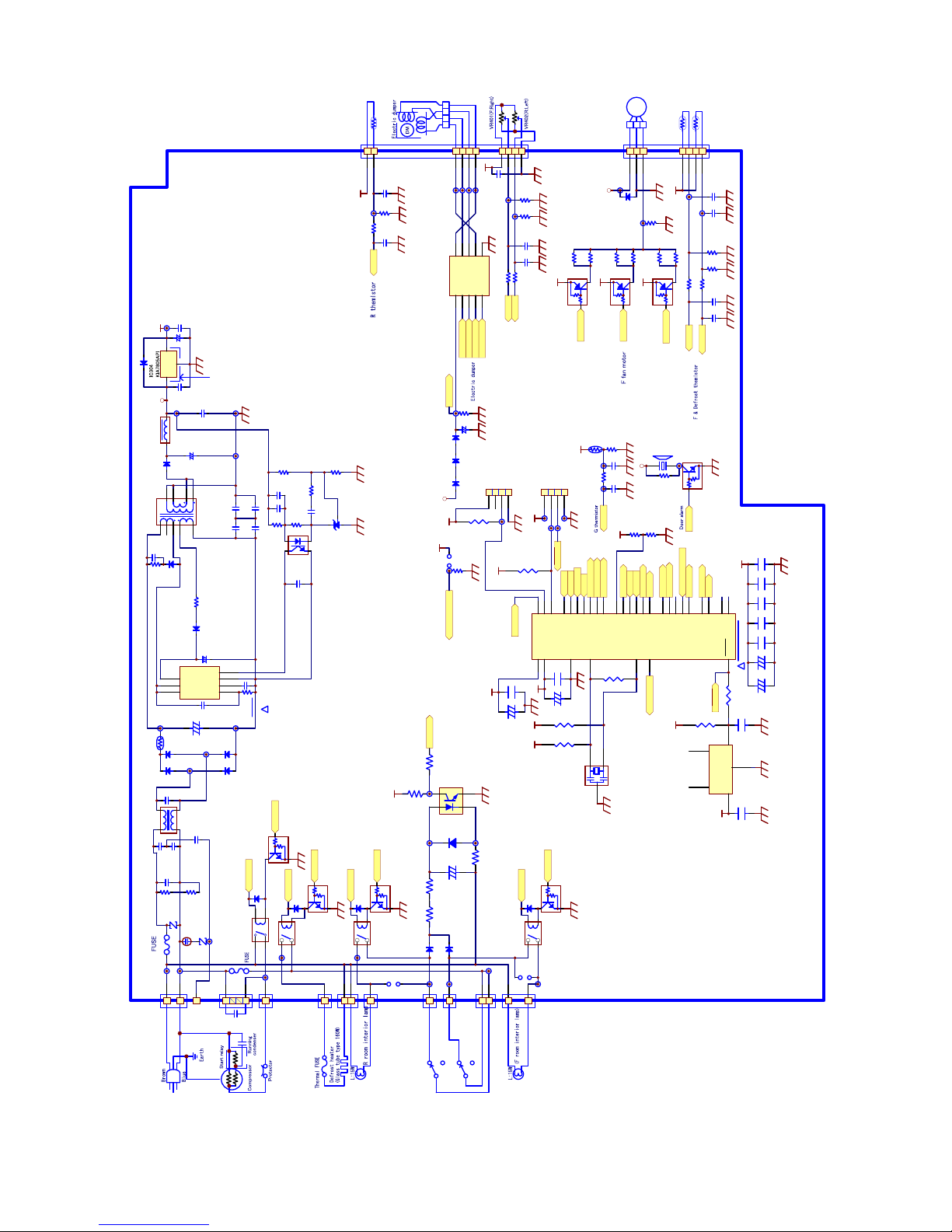
2. Main PWB (SJ-T52R/T56R)
DC5V
D309
1N4005SG
AC160-288V
50/60Hz
14.5V
1
2
4
3
RY302
FTR-F3
(C328)
1u/50V
C315
0.1u/25V
D308
1N4005SG
(C373)
10000pF
(C375)
10000pF
R311
R314
R309
4700p/50V
C316
1
2
34
PC301
PC123Y52
8.66kF
R308
C318
0.1u/50V
1k
1.8k
1.8kF
IC303
TA76431S
+
C314
100uF/10V
+
C312
560uF/25V
D303
D1NL20U
D302
EG01C
R305
R306
0.01u/400V
10
C309
C308
D304
RL2Z
R304
220k
47pF/2kV
1/2W1.0
+
C311
22uF /50V
910k(1/2W)
(AX)
+
C307
R301
82u/450V
F301
2.5A/250V
VRS301
TNR10V471K
C301
L301
SS26V-070510(51mH)
C302
0.1u/275V0.1u/275V
C321
0.1u
C320
0.1u
VDD
2
GND
3
VOUT
1
N.C.
4
N.C.
5
IC309
BD4842G
C319
0.01u
R383
10k
R393
1k
(R386)
1M
2
1
3
(CF301)
CST LS8M00G56-A0
P0032P0131P0230P0329P0428P0527P06
26
AN0
25
P3424P33
23
P1022P11
21
VREF
20
P1219P13
18
TXD0
17
P35
1
TXD1
2
RESET
3
XOUT
4
AVS S5XIN
6
AVC C
7
MODE
8
RXD1
9
P17
10
P3611P31
12
P5413P53
14
P16
15
RXD0
16
IC301
R5F21266SNFP
C323
0.1u
+C322
100u/10V
+(C324)
100u/10V
(RD)
(RD)
R387
10k
R388
10k
132
4
CN311
B4B-PH-KS
RESET
RESET
R389
10k
1
4
(CN303)
B2P(4-2,3)VH(LF)(SN)
1
CN310A
B7B-XASK-1-A(LF)(SN)
2
CN310B
B7B-XASK-1-A(LF)(SN)
3
CN310C
B7B-XASK-1-A(LF)(SN)
4
CN310D
B7B-XASK-1-A(LF)(SN)
5
CN310E
B7B-XASK-1-A(LF)(SN)
6
CN310F
B7B-XASK-1-A(LF)(SN)
7
CN310G
B7B-XASK-1-A(LF)(SN)
F-TH
DEF-TH
R-TH
F-TH
DEF-TH
R358
C356 C357
0.1uF/ 25V 0.1uF/ 25V
R356 4.7k
R357 4.7k
16.9kF
R359
16.9kF
(C354)
0.01u
(C355 )
0.01u
/50V
/50V
R-TH
R330
C337
0.1uF/ 25V
R329
4.7k
6.34kF
(C336)
0.01u
/50V
R353
F_FA N_H
F-FM
F_FA N_L
14.5V
(R351)
F_FA N_M
6.19kF
10kF
(Q317)
KRA101S
Q316
KRA101S
FFanmotor
14.5V
+
C342
100uF/25V
OUT110OUT29OUT38OUT4
7
IN12IN23IN34IN4
5
GND
6
VCC
1
IC306
LB1948M
D305
1N4005SG
DUMP_B1
DUMP_B2
DUMP_A1
DUMP_A2
D306
1N4005SG
D307
1N4005SG
910k(1/2W)
(AX)
R302
D316
1N4005SG
D317
D318
D319
F302
250V4A
COM
NO
NC
D312
1SS133
D310
1SS133
Q302
KRC101S
Q303
DTD123ES
DEF_H
Comp
R316
43k
(1/2W)
(AX)
R315
43k
(1/2W)
(AX)
R326
4.7k
AX (1 /4W)
D313
1SS133
1
3
2
4
PC302
PC123Y52
R312
4.7k
(1/10W)
R313
4.7k (1/10W)
+
C325
10uF/50V
COM
NO
NC
DoorSW
132
4
(CN312)
B4B-PH-KS
(R381)
4.7k
E8EmulatorConnector
RAM DataCheck
Vcc
Mode
Reset
Vss
TP313
C310
0.01u/50V
(L303)
TP301
R DOORSW
FDOORSW
TP302
TP344
ForIsraelonly
TP311
RY301
FTR-H2AL012T-SN
TP343
TP314 TP315
TP312
TP346
TP347
TP348
TP349
Film
Film
TP345
TP307
TP306
C376
10000pF
C377
10000pF
250V
TP309
TP8
TP325
TP328
TP329
TP330
TP331
TP336
TP337
TP341
TP340
(JMP 30 3)
OPEN
DC5V
R382
10k
TP326
C367
0.1u
+C364
100u/25V
C366
0.1u
+C365
100u/25V
C369
0.1u
C368
0.1u
C370
0.1u
DC5V
Ma in Control Board Ci rcuit Diagram
1.Ratingof reslstors without appointment are 1/10W, error 5%(J).
2.Ratingof capacitors without appointmentare 0.01u/50V,0.1u/50V.
3.Partswithparenthesesare not in use,but canbe inserted.
1N4005SG
1N4005SG
1N4005SG
(C317)
0.1u
TSL1112RA-100M3R7-PF
Vcc
GND
Vs
DC5V
DC5V
DC5V
DC5V
DC5V
DC5V
DC5V DC5V
DC5V
DC5V
DC5V
DC5V
DC5V
D301
1N4005SG
Q318
KRA101S
DC5V
(R361)
6.19kF
R352
10kF
(R362)
10kF
R350
3.16kF
(R360)
3.16kF
1
CN309A
B10-XASK-1-A(LF)(SN)
2
CN309B
B10-XASK-1-A(LF)(SN)
3
CN309C
B10-XASK-1-A(LF)(SN)
4
CN309D
B10-XASK-1-A(LF)(SN)
5
CN309E
B10-XASK-1-A(LF)(SN)
6
CN309F
B10-XASK-1-A(LF)(SN)
7
CN309G
B10-XASK-1-A(LF)(SN)
8
CN309H
B10-XASK-1-A(LF)(SN)
9
CN309I
B10-XASK-1-A(LF)(SN)
10
CN309J
B10-XASK-1-A(LF)(SN)
R343
C335 C332
0.1uF/ 25V 0.1uF/25V
R340 4.7k
R342 4.7k
220k
R341
220k
TP338
TP339
DC5V
(C330)
0.1uF/ 25V
F_VR
R_VR
GTH301
C16X-41-3S
R320
DC5V
(C381)
0.1u
R319
4.7k
10kF
(C380)
0.01u
TP332TP333
G_Th
(BZ301)
PKM22E P
(R318)
2.7k
(Q319)
KRC101S
14.5V
Buzzer
R391
10k
C304
SA301
RA-272M-C6-F
C306
C305
4700pF
4700pF
4700pF
/250VAC
VRS302
TNR10V511K
1
Tab3 01
Rating AC 220-240V50/60Hz
DC12V
DC12V
DC12V
1
CN301A
B3P( 5 -2 ,4)-VH(LF)(SN)
3
CN301B
B3P( 5 -2 ,4)-VH(LF)(SN)
5
CN301C
B3P( 5 -2 ,4)-VH(LF)(SN)
TP42098-21
1
CN306A
B5P( 7 -4 ,6)-VH(LF)(SN)
2
CN306B
B5P( 7 -4 ,6)-VH(LF)(SN)
3
CN306C
B5P(7-4,6)-VH(LF)(SN)
5
CN306D
B5P(7-4,6)-VH(LF)(SN)
7
CN306E
B5P(7-4,6)-VH(LF)(SN)
1
CN305A
B5P(8-2,5,7)-VH(LF)(SN)
3
CN305B
B5P( 8 -2 ,5,7)-VH(LF)(SN)
4
CN305C
B5P( 8 -2 ,5,7)-VH(LF)(SN)
6
CN305D
B5P(8-2,5,7)-VH(LF)(SN)
8
CN305E
B5P(8-2,5,7)-VH(LF)(SN)
1
2
4
3
(RY303)
FTR-F3
(D314)
1SS133
(Q321)
KRC101S
R_Lam p
DC12V
TP304
JMP301
Jumper
1
2
4
3
(RY304)
FTR-F3
(D315)
1SS133
(Q322)
KRC101S
DC12V
TP305
(JMP302)
OPEN
F_Lam p
TH301
S8R2K10D315J
D
8
D
7
VCC
5
S/OCP
1
FM/SS
2
GND
3
FB/CC/OLP
4
IC302
STR-A6251M
1W
(C327)
0.1u
AX 1/4W
Jumper
R307
AX 1/4W
1/4W
1/4W
TP9
C313
0.1u25V
3216
1
2
3
I
G
O
TP303
(D320)1N4005SG
1/4W
RK09K1130(10k)
Door SW input
Compressor
F-TH
DEF-TH
R-TH
F_FA N_H
F_FA N_L
F_FA N_M
DUMP_B1
DUMP_B2
DUMP_A1
DUMP_A2
F_VR
R_VR
G_Th
Buzzer
DEF_H
Comp
DoorSW
R_Lamp
ENFORCE_DEF
ENFORCE_DEF
F_Lam p
TP10
DC5V
TP334
R roomlamp(Bulb)
Defrost heater
F roomlamp(Bulb)
D3D-211
D3D-211
(Heat sink)
OSH-1025-SP2
54312
9106
7
TRANS301
123
Panasonic
2345
PH
2
1/2W1.2
2
R5F21265SNFP
(470uF/25V)
TP317
TP318
TP319
TP316
R395
DC5V
(R394)
10k
10k
Page 15
SJPT56RHS
5 – 6
3. LED PWB (Only for SJ-PT56R)
1 2
SSWW110011
SS
KK
QQ
NN
AADD
DD
001100
11 2
SS
WW110022
SS
KK
QQ
NN
AADD
DD
001100
11
2
SSWW110033
SSKKQQNNAADDDD001100
V
out
1
GND
2
Vin
3
IC102
KIA7
8
S05P
VL
T
X
D
,R
X
D
GND
+C1
02
47u/
2
5V
C1
01
0.
1
u/50V
C107
0
.1u
TP
101
(D101)
1N4005E
+
C103
47u/10V
+
5
V
VL
TP104
(R
D
)
(2
1
25
)
T
P
10
3
(
1608)
(RD)
T
P
10
2
RR11550
22..77kk
BZ101
PKM 1 3EPY
4kHz
+5
V
RR115522
11kk
RR11
5533
11kk
C1
10
0.
1u
V
DD
2
GND
3
VOUT
1
N.C.
4
N.C.
5
IC1
0
3
BD4842
G
C1
05
0.0
1u
+
5V
d3
d2
C1150.1u
C108
0.1u
(C
140
)
0.
1
u
R130
10kF
R131
4.7k
C1410.01u
GT
H
1
01
C
16X
-4
1-3S
+
5V
T
P
115
TP
116
Q
14
1
KRC101S
R14
2
2.2
k
+5V
RR114477
1k
R1
45
1k
C
132
0.01u
TP1
09
TP
11
0
R143
1
k
R14
4
1k
(R146)
1k
C13
1
0.0
1u
TP114
R1
41
2
..2kk
Q142
KRA101S
+5V
R170
2
.7
k
(C170)
0.01u
+5V +5V
R171
2.7
k
(C171)
0.0
1u
+
5V
+5V
S
W1
R172
2
.7k
(C172)
0.01u
+5V +5V
S
W
2
SW3
R162
820
R1
65
820
R164
820
R163
8
2
0
R160
820
R1
61
820
TT
PP
110055
TTPP110066
TT
PP
110077
TP
112
TP1
11
RXD0
R10110
k
+5V
R1
0
3
1
k
R
10
8
1
M
2
1
3
CF101
CS
T
LS
8M
00G56-A0
RXD0
TXD0
Q1
0
2
2SB1237
Q103
2SB1237
R166
820
VL VL
Q152
KRC1
01
S
Q153KRC1
01
S
SW2
S
W3
d3
d2
a
bcd
e
f
g
BZ
Q150
KRC101S
VL
Q155
KRC105S
R167
820
a
d1
DP
BZ
R156
4
.
7k
R157
4.7k
P00
32
P
0
1
31
P0230P03
29
P04
2288
P
05
2277
P06
2266
AN
0
2
5
P
34
24
P
33
23
P1022P11
21
VREF
20
P
12
19
P
13
18
TXD0
17
P
35
TXD
1
22
RESET
3
X
OU
T
4
AV
S
S
5
XIN
6
AVCC
7
MODE
88
R
X
D
1
99
P17
10
P36
P31
12
P54P53
11
11113
P
16
15
RXD0
16
IC101
R5F
2126
6S
N
F
P
11//
44
WW
11//
22WW
aa
1111
bb
7
cc
4
dd
2
ee
1
ff
10
gg
5
DD..PP11
3
DDiigg..11
1122
DDiigg..22
99
DDiigg..33
88
......
a
fbb
g
ec
d
DD..
PP..
LLEEDD110011
LLTTCC--556611A CBACB
123
CN101
S
03B-
P
A
S
K
-
2
C1110.
1u
+(C109)
100
u/
25V
+
(
C112)
1
00u/25V
(RD)
(RD)
(R195)
10k
(R194)
10
k
+5V
+
5
V
+5V
132
4
((CCNN110022))
B4B-PH-KL
+5V
RESET
RESET
1 2
SSWW110044
SSKK
QQ
NNAADDDD00
11
00
R173
2.7k
(C173)
0
..00
11uu
++55VV ++55VV
SW4
TP108
Q101
2SB1237
VL
R155
4.
7k
Q156
KRC105SbQ
15
7
KRC
1
05S
c
Q158KRC105SdQ159
KRC105SeQ160
KRC105SfQ1
6
1
KRC
10
5S
g
Q16
2
K
RC
105
S
DP
1/2W
1/2W
1/2W
1/2W
1/2W
1/2W
1/2W
R151
1k
d1
Q151
KRC101S
SW1
SW4
A
_
D
A
_D
TTPP112200
T
P
121
T
P
122
TP123
R178
10k
+5V
RR11
7744
44
..77kk
RR11
7755
44..77kk
RR11
7766
44
..77kk
R1774.7k
L
L
ED
ED
10310
2
Q
16
3
K
RC10
5S
LED10
2
VL
R168
820
L
E
D
102
(BL)
1/2W
TP125
Q164
KR
C10
5S
LED103
VL
R169
820
L
E
D
10
3
(BL)
1/
2
W
Flash writing
SW3
SW4
SW2
SW1
Page 16

SJPT56RHS
6 – 1
SJPT56RHS
Service Manual
CHAPTER 6. FAILURE DIAGNOSIS
[1] OUTLINE OF CONTROL
1. ON/OFF Control of Compressor
• ON/OFF of the compressor will be controlled depend on the temperature detected by
the R-thermistor and F-thermistor. (Normal cooling control)
• In case the surrounding temperature is high at the power supply input, the compressor will be ON at once and the normal cooling control will start
after several hours.
• During 5 minutes after the compressor stops, it will not start regardless of the detected temperature by R-thermistor and F-thermistor.
2. Defrosting
Microcomputer calculates the appropriate timing of defrosting and defrosting is made automatically. Therefore no manual operation by user is
required. The cycle of defrosting varies depend on the usage condition of the refrigerator. (Maximum time 50 hours, minimum time 40 minutes)
3. Thermistor
Thermistors are installed in 4 places; in the refrigerator and freezer compartment, and on the Main PWB and close to Evaporator. (R-thermistor, Fthermistor, Outside temp-thermistor, Def-thermistor)
R-thermistor and F-thermistor reads the temperature in the refrigerator and freezer compartment respectively and controls ON/OFF of the compressor and OPEN/CLOSE of the electrical damper.
Def-thermistor detects the temperature around the evaporator and shows the progress of defrosting.
Outside temp-thermistor reads the surrounding temperature of refrigerator. It changes the operation mode when the outside temperature is high.
[2] WHEN THE DEFROSTING FAILURE IS DOUBTFUL(Only for SJ-PT56R)
Execute the Self-Diagnosis Mode. (Refer to the Chapter “SELF-DIAGNOSIS MODE”)
• In case the diagnosis result is “ 03” (Def-thermistor system defect), follow up the flowchart of 03. (In case of any abnormity in the Def-thermistor, defrosting will not be made for safety reasons.)
• In case the diagnosis result is “ 07” (Defrost defect), follow up the flowchart of 07.
(This diagnosis result will be displayed when defrosting is made for 120 minutes, the maximum time length. In this case, the defect of PWB itself
and also the breakage of heater and heater circuit (melt down of current fuse and temperature fuse) are considerable.)
[3] RE-SETTING OF MICROCOMPUTER AT POWER FAILURE
• At the power failure for over 0.2 second, the control of the microcomputer will be reset.
(Microcomputer might continue to operate for approximately 10 seconds maximum at power failure depending on the load at the operation. When
you need the difinite power off condition ,approximately 30 seconds is necessary.)
• When the power is re-supplied, the normal cooling will be resumed.
• The temperature set by user is not maintained if a power failure occurred.(Only for SJ-PT56R)
(Defrosting also is not maintained.)
• When the self diagnosis is made, each mode and setting are resumed to the initial condition.(Only for SJ-PT56R)
Page 17
SJPT56RHS
6 – 2
[4] DIAGNOSIS METHOD OF FAILURE AROUND PWB
In case of any abnormality of refrigerator, check by the following procedure;
1. Disconnect power supply and check the following point.
• Is there any failure portion in inserting connectors?
2. Detach the PWB and check the appearance.
• Is there any burning or abnormal damage?
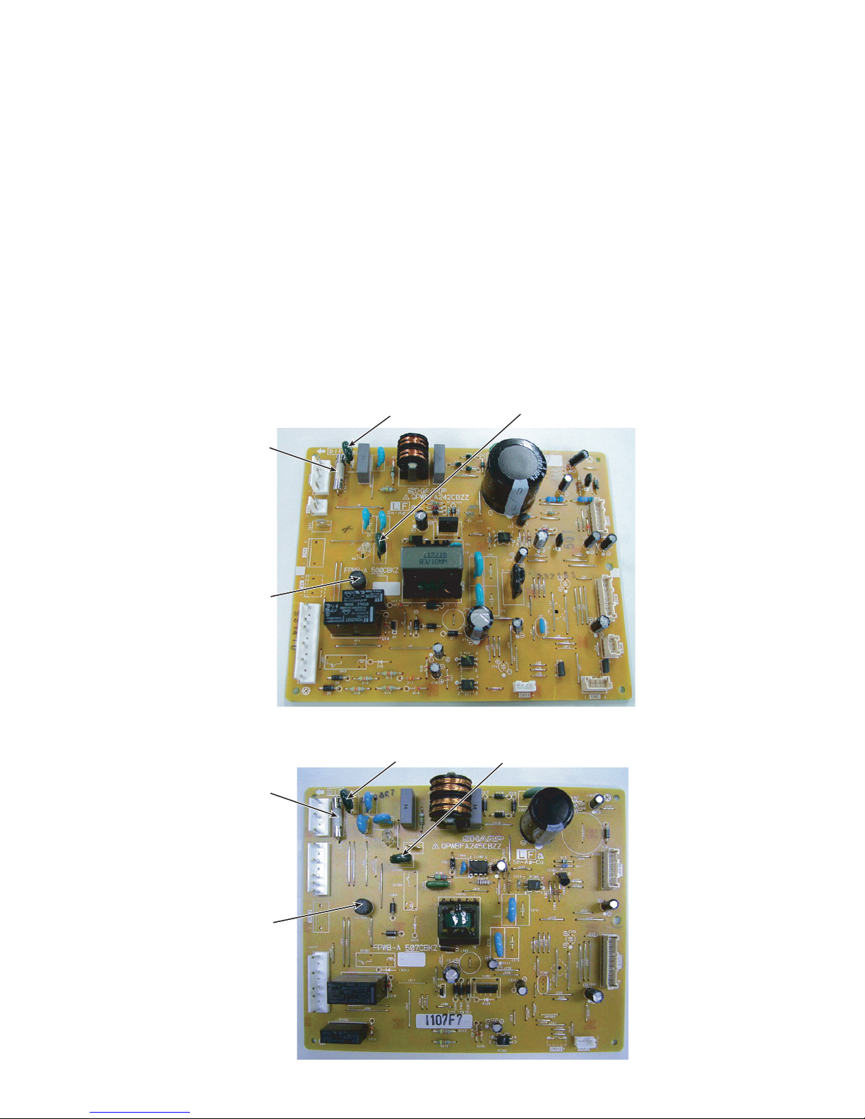
3. Check the conditions of the fuse and the varistor. (Fuse and varistor are located at the position in the figure.)
• Under the condition of power supply plug connected;
In case of no cooling and no indoor lamp lighting, there might be a possibility of fuse (F1) melt down.
In case of cooling but no indoor lamp lighting, there might be a possibility of fuse (F2) melt down.(Only for SJ-T52R, T56R)
(However, these indications do not conclude the cause of the defect.)
When the fuse F1 is melt down, PWB does not operate at all.
When the fuse F2 is melt down, indoor lamp bulb and defrosting heater are not electrified. (It will be diagnosed as “Defrosting failure” by the
self diagnosis.)
• Melting in the fuse cannot be checked visually (as the safer one than transparent glass tube is used). Be sure to detach the connector “CN1/
CN301” before measuring the resistance between the both ends of the fuse by the tester.
• Next, measure the resistance value between the both leads of the varistor.
1) SJ-PT56R
2) SJ-T52R / T56R
Fuse 1
Fuse 2
Varistor 1
Varistor 2
Fuse 1
Fuse 2
Varistor 1
Varistor 2
Page 18
SJPT56RHS
6 – 3
4. Check whether the temperature (resistance value) shown by R-thermistor is correct or not. (Refer to the table below.)
• Detach the connector “CN9/CN309” on the PWB and measure the resistance value between 1 and 2 pins.
5. Check whether the temperature (resistance value) shown by Def-thermistor is correct or not. (Refer to the table below.)
• Detach the connector “CN10/CN310” on the PWB and measure the resistance value between 6 and 7 pins.
6. Check whether the temperature (resistance value) shown by F-thermistor is correct or not. (Refer to the table below.)
• Detach the connector “CN10/CN310” on the PWB and measure the resistance value between 4 and 5 pins.
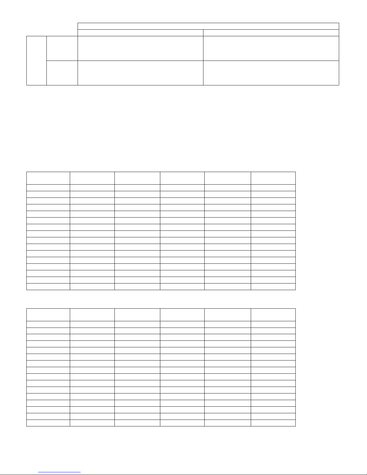
[5] CONVERSION TABLE BETWEEN TEMPERATURE AND RESISTANCE VALUE
1. R-thermistor, F-thermistor
2. Def-thermistor
Var isto r
Normal (over approx.1.8M) Damage
Fuse
Melting
Flow of excessive current is considerable for some reasons.
Check for any portion to cause short circuits especially on
the primary circuit.
There is a possibility of excessive voltage applied from outside with the factor such as thunder etc. When repeated with a
factor other than thunder, there might be the apparatus near
by generating noises.
Conduction
Fuse and varistor are normal.
Possibility to be caused by excessive current or voltage
near the power supply is low. Proceed to the other check
item.
-
Temperature
(C)
Resistance Value
(K)
Temperature
(C)
Resistance Value
(K)
Tem per atu re
(C)
Resistance Value
(K)
-25 26.1 -9 10.3 7 4.52
-24 24.54 -8 9.75 8 4.3
-23 23.08 -7 9.24 9 4.1
-22 21.72 -6 8.76 10 3.91
-21 20.46 -5 8.3 11 3.73
-20 19.27 -4 7.87 12 3.56
-19 18.16 -3 7.47 13 3.4
-18 17.13 -2 7.09 14 3.24
-17 16.16 -1 6.74 15 3.1
-16 15.25 0 6.4 20 2.47
-15 14.4 1 6.08 25 1.99
-14 13.6 2 5.78 30 1.61
-13 12.85 3 5.5 35 1.31
-12 12.15 4 5.23 40 1.08
-11 11.49 5 4.98
-10 10.88 6 4.74
Temperature
(C)
Resistance Value
(K)
Temperature
(C)
Resistance Value
(K)
Tem per atu re
(C)
Resistance Value
(K)
-25 61.17 -9 24.13 7 10.58
-24 57.51 -8 22.85 8 10.09
-23 54.1 -7 21.65 9 9.61
-22 50.92 -6 20.52 10 9.16
-21 47.94 -5 19.46 11 8.74
-20 45.17 -4 18.46 12 8.34
-19 42.57 -3 17.51 13 7.96
-18 40.14 -2 16.63 14 7.6
-17 37.86 -1 15.79 15 7.26
-16 35.74 0 15 20 5.79
-15 33.74 1 14.26 25 4.66
-14 31.87 2 13.55 30 3.77
-13 30.12 3 12.89 35 3.08
-12 28.48 4 12.26 40 2.52
-11 26.94 5 11.67
-10 25.49 6 11.11
Page 19

SJPT56RHS
7 – 1
SJPT56RHS
Service Manual
CHAPTER 7. SELF-DIAGNOSIS MODE (Only for SJ-PT56R)
1. Entering method of the mode
1) Press the [Select] button on the control panel over 5 seconds at the opening condition of
the freezer and refrigerating room doors.
2) With a beep sound of buzzer, the self-diagnosis mode is entered. When the self-diagnosis
mode is not entered by the above operation, defect of Door SW system can be considered.
2. When the self-diagnosis mode is entered, the following movements will be made. Forced release operation is not prepared for the self-diagnosis
mode. It returns to the normal movement after a lapse of 2 minutes.
• When the self-diagnosis mode is entered, beep sound for reminding of closing the door must not be sounded for 20 minutes.
• Defect and various conditions are displayed by [ON/OFF of buzzer].
• Defect and various conditions are displayed on the control panel. In case of plural defects and various conditions, these are displayed one after
another by button operation and all contents are notified.
3. Display of self-diagnosis
• Display example of control panel (at the defect of F-thermistor system)
• Buzzer notice example; (at defrost defect, 2 times of 0.5 second ON)
F
R
R
Select button
F
R
Result of diagnosis
Move to the next display
Move to the previous display
R
ON
OFF
3 seconds stop
Repeating
0.5 second stop
3 seconds stop
0.5 second stop
0.5 second 0.5 second 0.5 second 0.5 second
Buzzer
Page 20

SJPT56RHS
7 – 2
• Buzzer: =0.5 sec ON/0.5 sec OFF, =2 sec ON/0.5 sec OFF
No. Status Buzzer LED
Display
Content
Correspon-
dance
method
- No defects None - - - -
1 F-thermistor system defect
01
Defect of each thermistor, short circuit/wire breakage
of thermistor wiring and defect of main PWB
[1]
2 R-thermistor system defect
02
[2]
3 DEF-thermistor system defect
03
[3]
4
Outside temperature-thermistor system defect
04
[4]
5 Defrost defect
07
Wire breakage of fuse, defrost heater, defect of main
PWB
(120-minute defrosting has been occurred continuously 2 times within the past 48 hours.)
[5]
6 Fan motor system defect
08
Defect of wiring / main PWB
(When fan motor is ON, over current or no current is
detected.)
[6]
7
Ionizer (Plasmacluster) system
defect
11
Defect of wiring / main PWB
(When Plasmacluster is ON, over current or no current
is detected.)
[7]
8 LED Display communication defect
12
Short circuit/wire breakage of wiring and defect of LED
or main PWB (Communication with LED PWB has
been abnormal over 3 times within the past 48 hours.)
[8]
9 F-thermistor system defect history
61
Defect of thermistor system has been occurred over 1
minute continuously within the past 48 hours.
[1]
10 R-thermistor system defect history
62
[2]
11 DEF-thermistor system defect history
63
[3]
12
Outside temperature-thermistor
system defect history
64
[4]
13 F fan motor system defect history
66
Defect of fan motor has been occurred over 3 times
continuously within the past 48 hours.
[6]
14
Ionizer (Plasmacluster) electrifying
defect history
72
Defect of Ionizer (Plasmacluster) electrifying has been
occurred over 3 times continuously within the past 48
hours.
[7]
15 F-room high temperature history
76
Temperature of F-thermistor has been reached over
-10C continuously for 6 hours or more within the past
48 hours. (except right after the installation)
[1]
16 R-room high temperature history
77
Temperature of R-thermistor has been reached over
+10
C continuously for 6 hours or more within the past
48 hours. (except right after the installation)
[2]
Page 21

SJPT56RHS
7 – 3
Correspondence method
Power OFF Power OFF
Replace F-thermistor.
Replace main PWB.
NG?
NG?
(F-thermistor system diagnosis) (R-thermistor system diagnosis)
NO
NO
YES
YES
Remove 6P connector from E.V.
cover Assy and measure the
thermistor resistance between
and .
Replace R-thermistor.
Replace main PWB.
NG?
NG?
NO
NO
YES
YES
Remove 6P connector from R
louver Assy and measure the
thermistor resistance between
and .
01 / 61 / 76
02 / 62 / 77
[1]
[2]
10
3
4
9
56
2.47
Page 22

SJPT56RHS
7 – 4
(DEF-thermistor system diagnosis)
Power OFF
Replace DEF-thermistor.
Replace main PWB.
NG?
NG?
NO
NO
YES
YES
Remove 6P connector from E.V.
cover Assy and measure the
thermistor resistance between
and .
03 / 63
04 / 64
(Outside temperature - thermistor system diagnosis)
Replace Main-PWB.
Outside
temperature thermistor
is installed on
Main-PWB ass'y.
(Defrosting diagnosis)
07
Replace main PWB.
Replace fuse Assy.
Replace
defrost heater.
NO
YES
NO
YES
YES
NO
YES
NO (Open)
Forced defrosting (Measurement is impossible when
DEF-thermistor is set at 10°C or higher because
defrosting ends immediately)
After approx. 15 sec., the voltage
measured across
and of CN5
on the main PWB is equal to supplied
voltage? (e.g. 240 V)
Disconnect CN5 from the main PWB. Measure the
resistance between
and of CN on the wiring.
Check defrost heater wiring for loose
connection or disconnection.
Check cause of defrosting failure
· Check door packing
· Check mounting seal of E.V. cover Assy
[3]
[4]
[5]
5.8
approx. 280
(defrost heater 170~190W)
10
5
6
8
10
Turn power OFF. After approx. 30 sec.,
open door and re-energize.
(Buzzer beeps continuously)
8
10
Between 6P connector2and
4P connector
1(
white line) on
E.V. cover Assy is carrying current?
Resistance of 4P connector between
1
and2on E.V. cover K is normal? (331 )
Page 23

SJPT56RHS
7 – 5
YES
NO
08 / 66
(Fan motor system diagnosis)
Fan motor
rotates?
Check cause of defrosting
failure
· Dislocation of fan
· Check door packing
· Installation of E.V. cover Assy
· Defective seal
[6]
Replace LED-PWB Ass'y.
12
(LED system diagnosis)
Insert connector.
NO
NO
YES
CN8 on the main PWB is positively
engaged?
YES
[8]
Replace Plasmacluster.
(Ionizer system diagnosis)
Insert connector.
NO
NO
YES
and of CN9 on the main PWB
are positively engaged?
YES
and of 2P connector on R
louver Assy are positively engaged?
[7]
Under compressor operating,
close the door switch
Replace Fan motor or
main PWB
.
Fan locked ?
Check position of fan.
11
1
2
3P connector on LED control panel
is positively engaged?
YES
Page 24

SJPT56RHS
8 – 1
SJPT56RHS
Service Manual
CHAPTER 8. MODE FOR DISPLAY (Only for SJ-PT56R)
1. Entering method of the mode
Within 2 minutes after main power input, press the [ ] button over 3 seconds at the opening condition of the refrigerating room door.
2. Release of the mode
Press the [ ] button over 3 seconds at the opening condition of the refrigerating room door.
(Even without the above operation, release can be made by main power OFF.)
3. Movement in the mode
1) Compressor, fan motor, heater and Plasmacluster are stopped.
2) Damper is always made [CLOSE] condition.
3) Indoor lamp is lit when door is open.
4) LED display
• Temperature will be displayed in turn automatically.
5) Door alarm is operated only for freezer room door.
F
R
R
button
Page 25

SJPT56RHS
9 – 1
SJPT56RHS
Service Manual
CHAPTER 9. ASSEMBLING PROCEDURES OF MAIN PARTS AND CAUTIONS
CAUTION: DISCONNECT THE UNIT FROM THE POWER SUPPLY BEFORE ANY REPAIRING.
[1] FAN LOUVER AND E.V COVER ASSEMBLY
1. How to remove the Fan louver
1) Take out 2 screws with screw driver.
2) Pull the Fan louver toward yourself to take off.
Figure A-1
2. E.V cover assembly
1) Stick E.V cover sealer d to F fan motor. (Figure A-2)
Figure A-2
2) Insert terminal F-Thermistor and Def-thermistor in the housing.
(Figure A-3)
Figure A-3
3) Stick E.V cover sealer a and c to E.V cover. (Figure A-4)
Figure A-4
Screw
Screw
Fan louver
F fan motor
EV cover sealer d
OVER LAP
YLP-06V-B (VO)
F-THERMISTOR
DEF-THERMISTOR
FUSE ASS’Y
F-THERMISTOR
DEF-THERMISTOR
E.V cover sealer a
E.V cover sealer a
E.V cover sealer c
E.V cover sealer a
E.V cover
ABOUT THE SAME
Page 26

SJPT56RHS
9 – 2
4) Set Fan motor, F-thermistor, Def-thermistor, Fuse ass'y in the EV cover and stick Al tape. (Figure A-5)
Figure A-5
5) Set the Deodorizer to the Fan louver.(Only for SJ-PT56R)
Figure A-6
F fan motor
Def-thermistor
F-thermistor
STICK AL TAPE
SEC. AA
AL TAPE (T40 *W30*52L)
Fuse ass’y
Fan louver
Deodorizer
Page 27

SJPT56RHS
9 – 3
[2] R CONTOROL COVER ASSEMBLY (SJ-PT56R)
1) Stick Ra sealer c and Ra sealer d to R air guider b.
2) Insert Deodorizer to R air guider b.(Figure A-7)
3) Insert R air guider b to R air guider a.
4) Fix 2) ass'y with paper tape (Figure A-8)
5) Stick Ra-sealer a ,i,h,f,g U-sealer insu.b, and discharge sealer to 3)
ass'y.
6) Connect Plasma holder and connector of R-PLharness.
(Figure A-9)
7) Insert 6) ass'y to Plasma holder.
8) Insert 7) ass'y 5) ass'y.
9) Fix 8) ass'y with paper tape.
10)Stick A-sealer rc-d to Damper ass'y.(Figure A-10)
11)Insert Damper harness to Damper ass'y.
12)Insert 11) ass'y to 9) ass'y.
13)Stick A-sealer damper to 12) ass'y.
14)Fix 13) ass'y with paper tape.
Figure A-8
R air guider b
Ra sealer d
R air guider b
Deodorizer
Ra sealer C
Figure A-7
Ra sealer a
R air guider b
U-sealer insu.b
R air guider a
Ra sealer l
Ra sealer f
Ra sealer h
Ra sealer I
Ra sealer h
R air guider a
Ra sealer f
U-sealer insu.b
Ra sealerA
Damper Ass'y
A sealer damper
Discharge sealer
Ra sealer g
R-PL
Harness
Damper Ass'y
Ionizer-k
Plasma holder
Ra sealer a
Ra sealer f
Ra sealer h
R air guider a
R air guider a
Ra sealer f
㧔㨃㧟㧜㧝㧡㧜㨙㨙㧕
㧔㨃㧟㧜㧞㧜㧜㨙㨙㧕
㧔㨃㧟㧜㧝㧤㧜㨙㨙㧕
㧔㨃㧟㧜㧝㧜㧜㨙㨙㧕
㧔㨃㧟㧜㧝㧡㧜㨙㨙㧕
㧔㨃㧟㧜㧝㧡㧜㨙㨙㧕
㧔㨃㧟㧜㧝㧡㧜㨙㨙㧕
㧔㨃㧟㧜㧝㧡㧜㨙㨙㧕
㧔㨃㧟㧜㧞㧝㧜㨙㨙㧕
㧔㨃㧟㧜㧝㧡㧜㨙㨙㧕
㧔㨃㧟㧜㧝㧡㧜㨙㨙㧕
㧔㨃㧟㧜㧝㧡㧜㨙㨙㧕
Paper Tape
Paper Tape
Paper Tape
Paper Tape
Paper Tape
Paper Tape
Paper Tape
Paper Tape
Paper Tape
Paper Tape
Paper Tape
Paper Tape
Back side
SEC.BB
SEC.AA
A
A
B
B
Page 28

SJPT56RHS
9 – 4
15)Fix R LED PWB L ass'y to R-c box cover with tapping screw.
16)Insert the R-pl harness to 15) ass'y, and fix it to R-c box cover with paper tape.
17)Fix R-thermistor to R-c box cover,and stick R-thermistor sealer.
18)Stick Mask label to 17) ass'y.
19)Insert 14) ass'y to 18) ass'y.
20)Fix Lamp cover to 19) ass'y.
Figure A-11
Figure A-12
R-PLharness
Damper Harness
Plasma holder
Plasma holder
Plasma holder
R-PLharness
Connect IONIZER-K and connectorof R-PL harness
Connect should be inserted surely.
Figure A-9
Stick A-sealer rc-d to Damper ass'y
Insert Damper Harness to Damper ass'y
A-sealer RC-d
Damper ass'y
A-sealer RC-d
Figure A-10
R-C BOX-E
Mask Label
Tapping screw
R-PL Harness
R-Thermistor
R-Thermistor
Sealer
R-C Box Cover
R Led Lamp Pwb LAss'y
R-C Box Cover
R-Thermistor
R Air guider b
R Air guider a
R Led Lamp Pwb LAss'y
Paper tape
(30x60mm)
Page 29

SJPT56RHS
9 – 5
[3] R CONTOROL COVER ASSEMBLY (SJ-T52R/T56R)
1) Stick Ra sealer c and Ra sealer d to R air guider b.
2) Insert Deodorizer to R air guider b. (Figure A-13)
3) Insert R air guider b to R air guider a.
4) Insert R air guider c to 3)ass'y.
5) Fix 4) ass'y with paper tape. (Figure A-14)
6) Stick Ra-sealer a,i,h,f,g,U-sealer insu.b ,and Discharge sealer to
4)ass'y.
7) Stick A-sealer rc-d to Damper ass'y. (Figure A-15)
8) Insert Damper harness to Damper ass'y.(Figure A-15)
9) Insert 8) ass'y to 6) ass'y.
10)Stick A-sealer damper to 9) ass'y.
Figure A-14
Figure A-15
R air guider b
Ra sealer d
R air guider b
Deodorizer
Ra sealer c
Figure A-13
Ra sealer f
Ra sealer h
Ra sealer I
U-sealer insu.b
Ra sealer I
Ra sealer f
Paper Tape
Paper Tape
Paper Tape
Paper Tape
Paper Tape
Paper Tape
Paper Tape
Paper Tape
Paper Tape
Paper Tape
Dapmer Ass'y
Dapmer Harnes
A sealer damper
R air guider c
Ra sealer a
Discharge sealer
R air guider a
Ra sealer gRa sealer g
Ra sealer a
Ra sealer a
Ra sealer a
R air guider b
U-sealer insu.b
R air guider a
Ra sealer l
Ra sealer f
Ra sealer h
(W30x180mm)
(W30x150mm)
(W30x150mm)
(W30x100mm)
(W30x150mm)
(W30x150mm)
(W30x210mm)
(W30x150mm)
(W30x150mm)
(W30x150mm)
Back side
Stick A-sealer rc-d to Damper ass'y
Insert Damper harness to Damper ass'y
A-sealer rc-d
Damper ass'y
A-sealer rc-d
Damper harness
Page 30

SJPT56RHS
9 – 6
11)Fix 10) ass'y with paper tape.
12)Fix VR PWB ass'y to R-C box cover.
13)Insert Control knob to 12) ass'y.
14)Fix 13) ass'y with Waterproof tape.
15)Fix 14) ass'y with PWB sheet 55DR.
16)Fix Lamp ass'y to R lamp holder.
17)Fix 16)ass'y to Tapping screw.
18)Insert R-C box AL sheet to R-C box cover
After putting in two notches hole bent it 90
19)Insert Lamp harness to 18)ass'y.
20)Fix 19)ass'y to R-C box cover..
21)Fix R-thermistor to R-C box cover.
22)Stick R-thermistor sealer to R-C box cover.
23)Stick Warning label to R-C box AL sheet.
24)Fix 24) ass'y with paper tape.
25)Insert 11) ass'y to 25) ass'y.
Figure A-16
R-thermistor
Insert of pin
Note
Control knob
Control knob
PWB sheet 55DR
Pins should be insert surely,
and check by pulling it.
PL process
VR PWB ass’y
A
C
B
Rc box cover
Rc box AL sheet
Lamp Ass'y
R Lamp Holder
R-thermistor
Rc box AL sheet
RcboxALsheet
R sir guider a
R sir guider b
Rc box cover
Lamp Ass'y
R Lamp Holder
warning label
Contorol Knob
Control label
Paper Tape
Tapping screw
R Thermistor sealer
Lamp harness
Rlampholder
R Thermistor sealer
PWB Sheet
55DR
VR PWB
Ass'y
Paper Tape
Paper Tape
(30x30mm)
(30x30mm)
(30x60mm)
Control knob
PWB sheet 55DR
VR PWB ass’y
Page 31

SJPT56RHS
9 – 7
[4] R SHOWER DUCT ASSEMBLY
1. Fix R-shower ins. a to R shower duct.
Figure A-17
2. Stick A-sealer R-shower-d to “1” ass'y. (Figure A-18)
3. Fix Al panel to “2” ass'y. (Figure A-19)
Figure A-18 Figure A-19
R shower duct
R-shower ins.a
R-shower ins.a
Al panel
R-shower duct
R-shower ins.a
* One of the A-sealer R-shower-d is divided into 6 pieces
and the other is not divided.
A-sealer
R-shower-d
A-sealer
R-shower-d
Page 32

SJPT56RHS
9 – 8
[5] DEFROST HEATER ASSEMBLY
1. Taking-out Evaporator
1. Take-out Fan louver.
2. Take-out E.V cover ass’y.
Figure A-20
3. As shown in Figure A-20, pull the upper part of Evaporator toward
you, pull it diagonally so that the pipe of Evaporator does not contact the convex part of food liner.
Figure A-21
4. Pull the Evaporator for remove as shown in Figure-21.
NOTE: When pulling Evaporator and bending the pipes,pay attention
so as not to break and deform the pipes. Still, take care not to
hurt yourself by fin of Evaporator.
Figure A-22
2. Replacement of Def. heater ass’y.
1. Take off the Drain support al from the food liner.
Figure A-23
2. Raise the protrusion part of Drain support al.
Then remove Heater cover.
Figure A-24
3. Open Def.heater fixed part of Drain support al to the right and left,
then remove Def.heater ass’y.
Figure A-25
E vaporator
F ood liner c onvex pa rt
Food liner convex part
Evaporator
Pipe
Evaporator
Drain support al
Heater cover
Protrusion part of Drain support al (2 pcs.)
Heater cover
Def. heater ass'y
Drain support al
Protrusion part
Fixed parts
Def. heater ass'y
Drain support al
Page 33

SJPT56RHS
9 – 9
4. Replace Def. heater ass’y with new one.
Figure A-26
5. Bend the end of Drain support 90.
Figure A-27
6. Aseemble Defrost heater to Drain support al.
7. Assemble Heater cover to Drain support al. Bend top edge to outside.
8. Stick the Vinyl tape on the Lead wire of Defrost heater ass'y.
Figure A-28
3. Installing of Evaporator
1. Install Evaporator as shown in the Figure A-20 in the reverse order of Figure A-21
2. Correct the defromed fin.
NOTE: 1. When installing Evaporator, take care not to deform significantly and break the pipes.
2. Take care not to damage the lead wires and hurt yourself by the fin of Evaporator.
3. You shouldn’t touch Defrost heater with your bare hand. (You should wear pure gloves.)
4. You should wipe that with alcohol. When you touch Defrost heater with your bare hand.
Drain support al
Heater cover
Def. heater ass'y
Drain support al
Drain support al
Page 34

SJPT56RHS
10 – 1
SJPT56RHS
Service Manual
CHAPTER 10. COOLING UNIT
[1] COOLING UNIT
Hot pipe R
(Side condenser)
Hot pipe
(DP-condenser)
Hot pipe L
(Side condenser)
Evaporator
Suction pipe
Compressor
Capillary tube
Dryer
Back condenser
S.P connector
Discharge P connector
Eva pan pipe ass’y
Dryer
Connector
Mark: Brazing portion(copper to copper)
Mark: Brazing portion(steel to copper)
Mark: Refrigerant flow
Charge pipe
Charge pipe
Page 35

SJPT56RHS
10 – 2
[2] LOCATION
1. Location 1
2. Location 2
Capillary tube
Dryer
Charge pipe
Charge pipe L
Evaporator
Compressor
Eva pan pipe ass’y
Hot pipe
Back condenser
Mark shows pinch points
Mark shows welding points
(copper to copper)
Mark shows welding points
(steel to copper)
S.P
connector
Suction pipe
Discharge
P connector
Dryer
connector
Back condenser
to Hot pipe
Pinch point
Pinch Point
Dryer connector
to Dryer
Charge pipe
to Dryer
Hot pipe (outlet)
to Dryer connector
Dryer
to Capillary tube
Eva pan pipe ass'y
to Back condenser (inlet)
S.P connector
to Suction pipe
Charge pipe
to compressor’s
process tube
Compressor’s discharge pipe
to Discharge P. connector
S.P. connector
to compressor’s
suction pipe
Discharge P. connector
to Eva pan pipe ass'y
Page 36

SJPT56RHS
10 – 3
Page 37

PartsGuide
SJPT56RHS
PARTS GUIDE
Refrigerator-freezer
MODELS
SJ-PT56R-HS
SJ-T52R-S
SJ-T56R-S
SJ-PT56R SJ-T56R
[1] SJ-PT56R-HS CYCLE PARTS
[2] SJ-PT56R-HS MECHANIAL PARTS
[3] SJ-PT56R-HS DOOR PARTS
[4] SJ-PT56R-HS ATTACHMENT
PARTS
[5] SJ-PT56R-HS OTHER PARTS
[]
CONTENTS
[6] SJ-T52R/T56R-HS CYCLE PARTS
[7] SJ-T52R/T56R-HS MECHANIAL
PARTS
[8] SJ-T52R/T56R-HS DOOR PARTS
[9] SJ-T52R/T56R-HS ATTACHMENT
PARTS
[10] SJ-T52R/T56R-HS OTHER PARTS
INDEX
This document has been published to be used
for after sales service only.
The contents are subject to change without notice.
Page 38

SJPT56RHS
NO. PARTS CODE
PRICE
RANK
NEW
MARK
PAR T
RANK
DESCRIPTION
6-11
6-14
6-1
2-87
6-3
6-2
4-17
1-12
6-4
1-9
1-35
6-18
6-5
6-18
2-78
1-22
4-15
1-52
2-81
2-83
2-82
2-80
1-11
6-32
6-31
2-70
6-16
6-29
6-19
2-71
4-10
4-11
2-77
1-61
6-9
1-36
4-1 4-2
6-12
1-31
1-32
[1] SJ-PT56R-HS CYCLE PARTS
[1] SJ-PT56R-HS CYCLE PARTS
1-9 QACC-A160CBZZ AP Source cord
1-11 RHOG-A251CBZZ AZ Protector
1-12 RSTT-A219CBZZ AZ Ptc relay
1-22 FCNW-B019CBKZ AT Relay cord s ass'y
1-31 RC-EZA198CBZZ AZ Capacitor
1-32 QCNW-B021CBZZ AC Reray wire rc
1-35 QCNW-B295CBZZ AM Emi earth 2pin cr
1-36 QCNW-B283CBZZ AG Pwb earth wire
1-52 FPWB-A511CBKZ AY Main pwb ass'y
1-61 RCILFA011CBZZ AV Emi core esd-r-38
2-70 USRA-A313CBFA AP Drain pan
2-71 LHLD-A797CBFZ AE Ev.pan holder
2-77 LHLD-A359CBFA AE T-box holder
2-78 LPLTMA399CBP0 AD Dryer support
2-80 PBOX-A164CBFA AM Terminal box
2-81 PCOV-A396CBPZ AF Terminal cover
2-82 PCOVMA005CBYZ AF Terminal box cover
2-83 PSHEPA084CBZZ AG Terminal sheet
2-87 LBND-A018CBE0 AP Fastening band a
4-1 LBND-A023CBE0 AC L-band c
4-2 LBND-A019CBE0 AB Nylon band
4-10 QTAN-A013CBE0 AH Solderless term. A
4-11 QTAN-A012CBE0 AH Solderless term. B
4-15 LX-BZA090CBZZ AC Special screw
2
Page 39

SJPT56RHS
NO. PARTS CODE
PRICE
RANK
NEW
MARK
PAR T
RANK
[1] SJ-PT56R-HS CYCLE PARTS
4-17 LX-WZA035CBZZ AB Washer
6-1 PCMPLA371CBZZ CB Compressor
6-2 PSPAGA080CBZZ AK Rubber grommet
6-3 PSPAFA047CBEZ AE Sleeve
6-4 FFRM-A152CBKZ AH Base frame ass'y
6-5 FDRY-A006CBK0 AX Dryer ass'y
6-9 PCOVPA271CBEZ AH Terminal cover
6-11 PPIPCA624CBZZ AM S.p connector
6-12 PPIPCA625CBZZ AL Discharge connector
6-14 PGUM-A004CBF0 AH Absorbent rubber a
6-16 PGUM-A003CBF0 AH Absorbent rubber b
6-18 PPIPCA252CBE0 AD Charge pipe
6-19 PPIPCA551CBZZ AF Drier connector
6-29 LHLD-A465CBE0 AG Cord clip
6-31 FPIPCA307CBKZ AN Eva pan pipe s ass'y
6-32 LANG-A058CBPZ AC Absorbent rubber clm
DESCRIPTION
3
Page 40

SJPT56RHS
2-35
1-2
2-66
1-21
6-8
2-67
2-11
2-12
2-13
2-40
2-15
2-16
2-7
2-7-2
2-7-1
2-8
2-8-2
2-7-1
1-10
2-47
2-20
2-23
2-24
2-1
2-2
2-18
1-53
2-46
2-45
2-44
2-41
2-42
2-43
2-14
2-31
2-33
2-34
2-36
2-26
1-45
1-4
1-57
1-60
2-52
2-21
1-55
2-38
2-39
2-48
2-49
2-102
2-103
2-101
2-104
2-107
2-106
2-108
2-105
2-50
2-110
1-3
1-1
2-61
2-63
1-17
2-60
2-51
1-51
2-68
2-37
1-6
2-64
2-53
1-50
2-109
2-25
2-29
[2] SJ-PT56R-HS MECHANIAL PARTS
4
Page 41

NO. PARTS CODE
PRICE
RANK
NEW
MARK
PAR T
RANK
DESCRIPTION
[2] SJ-PT56R-HS MECHANIAL PARTS
1-1 RH-HXA104CBZZ AZ F-thermistor
1-2 RH-HXA103CBZZ AZ R-thermistor
1-3 RH-HXA105CBZZ AZ Def-thermistor
1-4 DTHM-A043CBKZ AX Damper ass'y
1-6 RMOTRA096CBZZ BE F fan motor
1-10 QSW-PA097CBZA AG Door switch
1-17 FFS-TA127CBKZ Fuse ass'y
1-21 FHETBA224CBZZ AP Def. Heater ass'y
1-45 FTRN-A014CBKZ AZ Ionaizer-k
1-50 LHLD-A801CBFA AE F-lamp holder
1-51 DPWB-A135CBKZ AY Led lamp pwb l ass'y
1-53 FPWB-A499CBKZ BG Led pwb ass'y
1-55 QCNW-B371CBZZ AL R-pl harness(51/55)
1-57 QCNW-B258CBZZ AP Damper harness
1-60 DPWB-A150CBKZ AY Rled lamp pwb l assy
2-1 GCOVPA237CBRA AU Control panel
2-2 GCOVPA279CBFA AF C-hinge slit cover
2-7 FLEGPA077CBKZ AQ Leg holder l ass'y
2-7-1 FAJS-A013CBK0 AE Adjustable leg ass'y
2-7-2 LHLD-A533CBPZ AL Leg holder l
2-8 FLEGPA078CBKZ AQ Leg holder r ass'y
2-8-2 LHLD-A534CBPZ AP Leg holder r
2-11 GCOV-A310CBFA AE Upper hinge cover
2-12 GCOV-A192CBFH AE Top cover
2-13 DHNG-A602CBMZ AG Upper hinge r ass'y
2-14 DHNG-A636CBMZ AG Bottom hinge r ass'y
2-15 DHNG-A686CBMZ AG Center hinge rt assy
2-16 DHNG-A687CBMZ AF Center hinge rb assy
2-18 LHLD-A825CBPZ AE C-box angler
2-20 GCOVPA277CBFA AR R-c box cover
2-21 LHLD-A714CBFZ AR Plasma holder
2-23 PGID-A206CBFZ AH R air guider a
2-24 PGID-A207CBFZ AH R air guider b
2-25 PSEL-C669CBZZ AD
2-26 PSEL-E092CBZZ AE Ra sealer a
2-29 PSEL-C958CBZZ AH A-sealer damper
2-31 LPLTMA847CBPZ AH Al panel
2-33 MLOV-A064CBFA AR R shower duct
2-34 PGID-A210CBFZ AG R-shower ins.a
2-35 PSEL-E097CBZZ AE A-sealer r-shower-d
2-36 PFIL-A047CBEZ AC Deodorizer
2-37 PFIL-A050CBEZ AM Deodorizer
2-38 GCOVPA234CBFA AE Leg cover l
2-39 GCOVPA235CBFA AE Leg cover r
2-40 LSTPPA161CBFA AE Case stopper
2-41 JBTN-A045CBRA AF Button fr
2-42 JBTN-A046CBRA AF Button dw
2-43 JBTN-A047CBRA AF Button up
2-44 JBTN-A048CBRA AF Button dc
2-45 JBTN-A049CBRA AF Button pl
2-46 LHLD-A802CBFA AE Led pwb holder
2-47 GDAI-A084CBTA AU Control box base
2-48 TLAB-B605CBRA AE Mask label
2-49 PSEL-D085CBZZ AD R thermistor sealer
2-50 HGRL-A269CBFA AU Fan louver
2-51 PCOV-A391CBRB AK F lamp cover
2-52 PCOV-A392CBRB AK R lamp cover
2-53 GCOVAA056CBFA AE Screw cover
2-60 GCOV-A311CBFZ AS E.v cover
2-61 PSEL-C959CBZZ AE E.v cover sealer a
2-63 PSEL-C961CBZZ AH E.v cover sealer c
2-64 PSEL-C601CBZZ AE Ev-cov.sealer c
2-66 PSHEMA341CBPZ AG Heater cover
2-67 LPLTMA819CBPZ AF Drain support
2-68 GCOVPA239CBFB AT Ev terminal cover
2-101 PSEL-E104CBZZ AE Ra sealer c
2-102 PSEL-E052CBZZ AE Ra sealer d
2-103
2-104 PSEL-E095CBZZ AF Ra sealer f
2-105 PSEL-E103CBZZ AE Ra sealer g
2-106 PSEL-E107CBZZ AF Ra sealer h
2-107 PSEL-E108CBZZ AF Ra sealer i
2-108 PSEL-C948CBZZ AE U-sealer insu b
2-109 PFPFPC008CBFZ AE E.v cover insu.a
2-110 PSEL-E193CBZZ AF Fan louver sealer a
PSEL-E053CBZZ AE Discharge sealer
6-8 PEVA-A225CBZZ Evaporator
A-sealer rc-d
SJPT56RHS
5
Page 42

SJPT56RHS
[3] SJ-PT56R-HS DOOR PARTS
3-22
3-22
3-22
3-3
3-10
3-10
3-10
3-4
3-4
3-8
3-7
3-5
3-31
3-6
3-9
3-31
3-8
3-31
3-6
3-20
3-1
3-2
3-21
3-30
3-1-1
3-1-2
3-22
3-13
3-10
3-7
3-9
3-31
3-5
3-11-3
3-11
3-12
3-11-1
3-11-4
3-11-2
6
Page 43

NO. PARTS CODE
PRICE
RANK
NEW
MARK
PAR T
RANK
DESCRIPTION
[3] SJ-PT56R-HS DOOR PARTS
3-1 FDORFB986CBKZ BR F-door ass'y
3-1-1 LSTPMA028CBMZ AE F-door stopper r
3-1-2 LSTPPA158CBFA AE Fd-stopper spring r
3-2 FPACGA519CBKZ AY F-door packing
3-3 JHNDPA285CBPZ AQ F door handle
3-4 HDECQA544CBTA AF Hd cover t
3-5 HDECQA545CBTA AF Hd cover b
3-6 LPLTPA478CBTA AH Hd base t
3-7 LPLTPA479CBTA AH Hd base b
3-8 LPLTPA480CBPZ AF Hd support t
3-9 LPLTPA481CBPZ AF Hd support b
3-10 LX-BZA112CBZZ AD Handle screw 5x20
3-11 FDORRB891CBKZ BS R-door ass'y
3-11-1 LSTP-A064CBMZ AE R-door stopper r
3-11-2 LSTPPA159CBFA AE Rd-stopper spring r
3-11-3 NBRGPA022CBFA AC Nylon bearing 3s
3-11-4 LPLTMA846CBMZ AF Rd-support
3-12 FPACGA520CBKZ AZ R-door packing
3-13 JHNDPA286CBPZ AQ R door handle
3-20 PCAP-A055CBFF AE Bearing cap
3-21 HBDGDB043CBJA AP Badge
3-22 GCOVAA052CBTA AE Screw cover
3-30 PPACGA268CBZA AL F-sub. Packing
3-31 PCUS-A014CBZZ AD Hd-support cushion
SJPT56RHS
7
Page 44

SJPT56RHS
[4] SJ-PT56R-HS ATTACHMENT PARTS
5-12
5-1
5-3
5-4
5-6
5-15
5-14
5-13
5-11
5-16
5-17
5-8
5-10
5-7
5-19
5-18
5-5
5-7
5-20
5-9
5-22
5-3
5-21
8
Page 45

NO. PARTS CODE
PRICE
RANK
NEW
MARK
PAR T
RANK
DESCRIPTION
[4] SJ-PT56R-HS ATTACHMENT PARTS
5-1 FPOK-A277CBKZ AS F-door pocket ass'y
5-3 UPOKPA308CBFB AN Rf door pocket
5-4 GDORPA086CBRB AM R door pocket cover
5-5 UPOKPA340CBFB AK Utility pocket
5-6 UPOKPA310CBFB AP R door pocket
5-7 UTNA-A282CBFC AF Egg tray
5-8 UPOKPA314CBFB AM Utility pocket l
5-9 UPOKPA312CBFB AT Bottle pocket
5-10 UPOKPA251CBFE AG Tube stand
5-11 UTNA-A450CBFB AR F shelf s
5-12 UTNA-A449CBFB BA F shelf
5-13 FSRA-A273CBYZ AR Ice cube maker
5-14 UYOK-A579CBFB AN Ice storage box
5-15 GDORPA085CBFB AN Fresh door
5-16 UYOK-A577CBFB AY Fresh case
5-17 FTNA-A512CBKZ AY R glass shelf ass'y
5-18 FTNA-A465CBKZ AY R glass shelf sf asy
5-19 FTNA-A466CBKZ AY R glass shelf sb asy
5-20 FTNA-A510CBKZ AY V glass shelf ass'y
5-21 UYOK-A578CBFB AY Vegetable case
5-22 LSTYPA047CBFA AN Partition v
[5] SJ-PT56R-HS OTHER PARTS
1-32 QCNW-B021CBZZ AC Reray wire rc
90-1 TINS-B160CBRZ AS Operation manual
90-3 SPAKCA611CBZZ BD Packing case 55cr-f-2
90-6 CPADBA108CBKZ BA Bottom pad ass'y
90-7 CPADBA109CBKZ AP Top pad ass'y
90-19 TINS-A366CBR0 AC Srv.station list
90-20 FGAN-A070CBR0 AD Warranty card scot
SJPT56RHS
9
Page 46

SJPT56RHS
NO. PARTS CODE
PRICE
RANK
NEW
MARK
PAR T
RANK
DESCRIPTION
[6] SJ-T52R/T56R-HS CYCLE PARTS
6-32
6-19
6-18
6-5
2-78
2-71
1-32
6-12
6-2
1-31
6-3
6-31
4-1
6-11
1-22
2-80
6-16
6-1
6-14
4-17
1-52
6-18
1-12
4-11
2-70
4-10
2-83
1-11
6-29
6-9
2-87
1-9
2-81
4-15
6-4
[6] SJ-T52R/T56R-HS CYCLE PARTS
1-9 QACC-A160CBZZ AP Source cord
1-11 RHOG-A251CBZZ AZ Protector
1-12 RSTT-A219CBZZ AZ Ptc relay
1-22 FCNW-B019CBKZ AT Relay cord s ass'y
1-31 RC-EZA198CBZZ AZ Capacitor
1-32 QCNW-B021CBZZ AC Reray wire rc
1-36 QCNW-B283CBZZ AG Pwb earth wire
1-39 QCNW-A887CBE0 AG Earth wire
1-52 FPWB-A513CBKZ BK Main pwb ass'y
2-70 USRA-A313CBFA AP Drain pan
2-71 LHLD-A797CBFZ AE Ev.pan holder
2-77 LHLD-A359CBFA AE T-box holder
2-78 LPLTMA399CBP0 AD Dryer support
2-80 PBOX-A164CBFA AM Terminal box
2-81 PCOV-A396CBPZ AF Terminal cover
2-82 PCOVMA005CBYZ AF Terminal box cover
2-83 PSHEPA084CBZZ AG Terminal sheet
2-87 LBND-A018CBE0 AP Fastening band a
4-1 LBND-A023CBE0 AC L-band c
4-10 QTAN-A013CBE0 AH Solderless term. A
4-11 QTAN-A012CBE0 AH Solderless term. B
4-15 LX-BZA090CBZZ AC Special screw
4-17 LX-WZA035CBZZ AB Washer
6-1 PCMPLA371CBZZ CB Compressor
2-82
1-36
2-77
1-39
10
Page 47

SJPT56RHS
NO. PARTS CODE
PRICE
RANK
NEW
MARK
PAR T
RANK
[6] SJ-T52R/T56R-HS CYCLE PARTS
6-2 PSPAGA080CBZZ AK Rubber grommet
6-3 PSPAFA047CBEZ AE Sleeve
6-4 FFRM-A153CBKZ AK Base frame ass'y
6-5 FDRY-A006CBK0 AX Dryer ass'y
6-9 PCOVPA271CBEZ AH Terminal cover
6-11 PPIPCA624CBZZ AM S.p connector
6-12 PPIPCA625CBZZ AL Discharge connector
6-14 PGUM-A004CBF0 AH Absorbent rubber a
6-16 PGUM-A003CBF0 AH Absorbent rubber b
6-18 PPIPCA252CBE0 AD Charge pipe
6-19 PPIPCA551CBZZ AF Drier connector
6-29 LHLD-A465CBE0 AG Cord clip
6-31 FPIPCA307CBKZ AN Eva pan pipe s ass'y
6-32 LANG-A058CBPZ AC Absorbent rubber clm
DESCRIPTION
11
Page 48

SJPT56RHS
2-30
2-66
1-21
6-8
2-67
2-11
2-13
2-40
2-15
2-54
2-7
2-7-2
2-7-1
2-8
2-8-2
2-7-1
1-10
2-55
2-20
2-23
2-24
2-14
90-31
2-31
2-33
2-34
2-35
2-22
1-7
1-2
2-52
2-88
90-2
1-55
2-38
2-39
1-54
2-89
2-19
2-49
2-55
2-102
2-101
2-104
2-36
2-26
1-4
1-57
2-103
2-107
2-106
2-108
2-105
1-58
2-50
2-110
1-3
1-1
2-61
2-63
1-17
2-60
2-51
2-68
1-6
2-64
2-53
2-109
2-25
2-29
[7] SJ-T52R/T56R-HS MECHANIAL PARTS
12
Page 49

NO. PARTS CODE
PRICE
RANK
NEW
MARK
PAR T
RANK
DESCRIPTION
[7] SJ-T52R/T56R-HS MECHANIAL PARTS
1-1 RH-HXA104CBZZ AZ F-thermistor
1-2 RH-HXA103CBZZ AZ R-thermistor
1-3 RH-HXA105CBZZ AZ Def-thermistor
1-4 DTHM-A043CBKZ AX Damper ass'y
1-6 RMOTRA096CBZZ BE F fan motor
1-7 FLMP-A005CBZZ AL Lamp ass'y
1-10 QSW-PA097CBZA AG Door switch
1-17 FFS-TA127CBKZ Fuse ass'y
1-21 FHETBA224CBZZ AP Def. Heater ass'y
1-54 FPWB-A554CBKZ AY Vr pwb ass'y
1-55 QCNW-B270CBZZ AH Lamp harness
1-57 QCNW-B258CBZZ AP Damper harness
1-58 QCNW-B304CBZZ AK Control harness
2-7 FLEGPA077CBKZ AQ Leg holder l ass'y
2-7-1 FAJS-A013CBK0 AE Adjustable leg ass'y
2-7-2 LHLD-A533CBPZ AL Leg holder l
2-8 FLEGPA078CBKZ AQ Leg holder r ass'y
2-8-2 LHLD-A534CBPZ AP Leg holder r
2-11 GCOV-A310CBFE AE Upper hinge cover
2-13 DHNG-A602CBMZ AG Upper hinge r ass'y
2-14 DHNG-A636CBMZ AG Bottom hinge r ass'y
2-15 DHNG-A611CBMZ AG Center hinge r ass'y
2-19 LPLTMA840CBPZ AE R-cbox al sheet
2-20 GCOVPA277CBFA AR R-c box cover
2-22 LHLD-A803CBFZ AG R lamp holder
2-23 PGID-A206CBFZ AH R air guider a
2-24 PGID-A207CBFZ AH R air guider b
2-25 PSEL-C669CBZZ AD A-sealer rc-d
2-26 PSEL-E092CBZZ AE Ra sealer a
2-29 PSEL-C958CBZZ AH A-sealer damper
2-30 PGID-A177CBFZ AG R air guider c
2-31 LPLTMA847CBPZ AH Al panel [T56R]
2-31 LPLTMA848CBPZ AH Al panel [T52R]
2-33 MLOV-A064CBFA AR
2-33 MLOV-A065CBFA AR R shower duct [T52R]
2-34 PGID-A210CBFZ AG R-shower ins.a [T56R]
2-34 PGID-A211CBFZ AG R-shower ins.a [T52R]
2-35 PSEL-E097CBZZ AE A-sealer r-shower-d [T56R]
2-35 PSEL-E099CBZZ AE A-sealer r-shower-d [T52R]
2-36 PFIL-A047CBEZ AC Deodorizer
2-38 GCOVPA234CBFA AE Leg cover l
2-39 GCOVPA235CBFA AE Leg cover r
2-40 LSTPPA161CBFA AE Case stopper
2-49 PSEL-D085CBZZ AD R thermistor sealer
2-50 HGRL-A269CBFA AU Fan louver
2-51 PCOV-A395CBRA AH F lamp cover
2-52 PCOV-A390CBFB AE R lamp cover
2-53 GCOVAA056CBFA AE Screw cover
2-54 PCAP-A077CBFA AA Screw cover
2-55 PCAP-A006CBFW AB Screw cover
2-60 GCOV-A311CBFZ AS E.v cover
2-61 PSEL-C959CBZZ AE E.v cover sealer a
2-63 PSEL-C961CBZZ AH E.v cover sealer c
2-64 PSEL-C601CBZZ AE Ev-cov.sealer c
2-66 PSHEMA341CBPZ AG Heater cover
2-67 LPLTMA819CBPZ AF Drain support
2-68 GCOVPA239CBFB AT Ev terminal cover
2-88 JKNB-A085CBFA AF Control knob
2-89 LPLTPA490CBZZ AE Pwb sheet 55dr
2-101 PSEL-E104CBZZ AE Ra sealer c
2-102 PSEL-E052CBZZ AE Ra sealer d
2-103 PSEL-E053CBZZ AE Discharge sealer
2-104 PSEL-E095CBZZ AF Ra sealer f
2-105 PSEL-E103CBZZ AE Ra sealer g
2-106 PSEL-E107CBZZ AF Ra sealer h
2-107 PSEL-E108CBZZ AF Ra sealer i
2-108 PSEL-C948CBZZ AE U-sealer insu b
2-109
2-110 PSEL-E193CBZZ AF Fan louver sealer a
90-31 HPNLCA085CBRA Control label
PFPFPC008CBFZ AE E.v cover insu.a
6-8 PEVA-A225CBZZ Evaporator
90-2 TLAB-A874CBRZ AC Warning label
R shower duct [T56R]
SJPT56RHS
13
Page 50

SJPT56RHS
[8] SJ-T52R/T56R-HS DOOR PARTS
3-2
3-1
3-4
3-6
3-11
3-21
3-30
3-1-1
3-1-2
3-14
3-16
3-11-1
3-12
3-11-4
3-11-2
14
Page 51

NO. PARTS CODE
PRICE
RANK
NEW
MARK
PAR T
RANK
DESCRIPTION
[8] SJ-T52R/T56R-HS DOOR PARTS
3-1 FDORFC081CBKZ BR F-door ass'y
3-1-1 LSTPMA028CBMZ AE F-door stopper r
3-1-2 LSTPPA158CBFA AE Fd-stopper spring r
3-2 FPACGA519CBKZ AY F-door packing
3-4 HDECQA550CBTA AL Hd cover f
3-6 LPLTPA491CBFA AP Handle base f
3-11 FDORRC105CBKZ BT R-door ass'y [T56R]
3-11 FDORRC107CBKZ BT R-door ass'y [T52R]
3-11-1 LSTP-A064CBMZ AE R-door stopper r
3-11-2 LSTPPA159CBFA AE Rd-stopper spring r
3-11-4 LPLTMA846CBMZ AF Rd-support
3-12 FPACGA520CBKZ AZ R-door packing [T56R]
3-12 FPACGA521CBKZ AZ R-door packing [T52R]
3-14 HDECQA551CBTA AM Hd cover r
3-16 LPLTPA492CBFA AP Handle base r
3-21 HBDGDB043CBJA AP Badge
3-30 PPACGA268CBZA AL F-sub. Packing
SJPT56RHS
15
Page 52

SJPT56RHS
[9] SJ-T52R/T56R-HS ATTACHMENT PARTS
5-1
5-12
5-8
5-13
5-3
5-6
5-14
5-16
5-15
5-17
5-17
5-7
5-9
5-10
5-3
5-5
5-20
5-22
5-21
16
Page 53

NO. PARTS CODE
PRICE
RANK
NEW
MARK
PAR T
RANK
DESCRIPTION
[9] SJ-T52R/T56R-HS ATTACHMENT PARTS
5-1 FPOK-A277CBKZ AS F-door pocket ass'y
5-3 UPOKPA308CBFB AN Rf door pocket
5-5 UPOKPA340CBFB AK Utility pocket
5-6 UPOKPA310CBFB AP R door pocket
5-7 UTNA-A282CBFC AF Egg tray
5-8 UPOKPA314CBFB AM Utility pocket l [T56R]
5-9 UPOKPA312CBFB AT Bottle pocket
5-10 UPOKPA251CBFE AG Tube stand
5-12 UTNA-A449CBFB BA F shelf
5-13 FSRA-A275CBYZ AR Ice cube maker
5-14 UYOK-A579CBFB AN Ice storage box
5-15 GDORPA085CBFB AN Fresh door
5-16 UYOK-A577CBFB AY Fresh case
5-17 FTNA-A506CBKZ BD R glass shelf ass'y
5-20 FTNA-A505CBKZ BE V glass shelf ass'y
5-21 UYOK-A578CBFB AY Vegetable case
5-22 LSTYPA047CBFA AN Partition v
[10] SJ-T52R/T56R-HS OTHER PARTS
90-1 TINS-B161CBRZ AS Operation manual
90-3 SPAKCA611CBZZ BD Packing case 55cr-f-2 [T56R]
90-3 SPAKCA613CBZZ BD Packing case 51dr-f-2 [T52R]
90-6 CPADBA108CBKZ BA Bottom pad ass'y
90-7 CPADBA109CBKZ AP Top pad ass'y
90-19 TINS-A366CBR0 AC Srv.station list
90-20 FGAN-A070CBR0 AD Warranty card scot
SJPT56RHS
17
Page 54

SJPT56RHS
INDEX
PARTS CODE No.
[ C ]
CPADBA108CBKZ 5-90-6 BA
" 10-90-6 BA
CPADBA109CBKZ 5-90-7 AP
" 10-90-7 AP
[ D ]
DHNG-A602CBMZ 2-2-13 AG
" 7-2-13 AG
DHNG-A611CBMZ 7-2-15 AG
DHNG-A636CBMZ 2-2-14 AG
" 7-2-14 AG
DHNG-A686CBMZ 2-2-15 AG
DHNG-A687CBMZ 2-2-16 AF
DPWB-A135CBKZ 2-1-51 AY
DPWB-A150CBKZ 2-1-60 AY
DTHM-A043CBKZ 2-1-4 AX
" 7-1-4 AX
[ F ]
FAJS-A013CBK0 2-2-7-1 AE
" 7-2-7-1 AE
FCNW-B019CBKZ 1-1-22 AT
" 6-1-22 AT
FDORFB986CBKZ 3-3-1 BR
FDORFC081CBKZ 8-3-1 BR
FDORRB891CBKZ 3-3-11 BS
FDORRC105CBKZ 8-3-11 BT
FDORRC107CBKZ 8-3-11 BT
FDRY-A006CBK0 1-6-5 AX
" 6-6-5 AX
FFRM-A152CBKZ 1-6-4 AH
FFRM-A153CBKZ 6-6-4 AK
FFS-TA127CBKZ 2-1-17
" 7-1-17
FGAN-A070CBR0 5-90-20 AD
" 10-90-20 AD
FHETBA224CBZZ 2-1-21 AP
" 7-1-21 AP
FLEGPA077CBKZ 2-2-7 AQ
" 7-2-7 AQ
FLEGPA078CBKZ 2-2-8 AQ
" 7-2-8 AQ
FLMP-A005CBZZ 7-1-7 AL
FPACGA519CBKZ 3-3-2 AY
" 8-3-2 AY
FPACGA520CBKZ 3-3-12 AZ
" 8-3-12 AZ
FPACGA521CBKZ 8-3-12 AZ
FPIPCA307CBKZ 1-6-31 AN
" 6-6-31 AN
FPOK-A277CBKZ 4-5-1 AS
" 9-5-1 AS
FPWB-A499CBKZ 2-1-53 BG
FPWB-A511CBKZ 1-1-52 AY
FPWB-A513CBKZ 6-1-52 BK
FPWB-A554CBKZ 7-1-54 AY
FSRA-A273CBYZ 4-5-13 AR
FSRA-A275CBYZ 9-5-13 AR
FTNA-A465CBKZ 4-5-18 AY
FTNA-A466CBKZ 4-5-19 AY
FTNA-A505CBKZ 9-5-20 BE
FTNA-A506CBKZ 9-5-17 BD
FTNA-A510CBKZ 4-5-20 AY
FTNA-A512CBKZ 4-5-17 AY
FTRN-A014CBKZ 2-1-45 AZ
[ G ]
GCOV-A192CBFH 2-2-12 AE
GCOV-A310CBFA 2-2-11 AE
GCOV-A310CBFE 7-2-11 AE
GCOV-A311CBFZ 2-2-60 AS
" 7-2-60 AS
GCOVAA052CBTA 3-3-22 AE
GCOVAA056CBFA 2-2-53 AE
" 7-2-53 AE
GCOVPA234CBFA 2-2-38 AE
" 7-2-38 AE
GCOVPA235CBFA 2-2-39 AE
" 7-2-39 AE
GCOVPA237CBRA 2-2-1 AU
GCOVPA239CBFB 2-2-68 AT
PRICE
RANK
NEW
MARK
PAR T
RANK
PARTS CODE No.
" 7-2-68 AT
GCOVPA277CBFA 2-2-20 AR
" 7-2-20 AR
GCOVPA279CBFA 2-2-2 AF
GDAI-A084CBTA 2-2-47 AU
GDORPA085CBFB 4-5-15 AN
" 9-5-15 AN
GDORPA086CBRB 4-5-4 AM
[ H ]
HBDGDB043CBJA 3-3-21 AP
" 8-3-21 AP
HDECQA544CBTA 3-3-4 AF
HDECQA545CBTA 3-3-5 AF
HDECQA550CBTA 8-3-4 AL
HDECQA551CBTA 8-3-14 AM
HGRL-A269CBFA 2-2-50 AU
" 7-2-50 AU
HPNLCA085CBRA 7-90-31
[ J ]
JBTN-A045CBRA 2-2-41 AF
JBTN-A046CBRA 2-2-42 AF
JBTN-A047CBRA 2-2-43 AF
JBTN-A048CBRA 2-2-44 AF
JBTN-A049CBRA 2-2-45 AF
JHNDPA285CBPZ 3-3-3 AQ
JHNDPA286CBPZ 3-3-13 AQ
JKNB-A085CBFA 7-2-88 AF
[ L ]
LANG-A058CBPZ 1-6-32 AC
" 6-6-32 AC
LBND-A018CBE0 1-2-87 AP
" 6-2-87 AP
LBND-A019CBE0 1-4-2 AB
LBND-A023CBE0 1-4-1 AC
" 6-4-1 AC
LHLD-A359CBFA 1-2-77 AE
" 6-2-77 AE
LHLD-A465CBE0 1-6-29 AG
" 6-6-29 AG
LHLD-A533CBPZ 2-2-7-2 AL
" 7-2-7-2 AL
LHLD-A534CBPZ 2-2-8-2 AP
" 7-2-8-2 AP
LHLD-A714CBFZ 2-2-21 AR
LHLD-A797CBFZ 1-2-71 AE
" 6-2-71 AE
LHLD-A801CBFA 2-1-50 AE
LHLD-A802CBFA 2-2-46 AE
LHLD-A803CBFZ 7-2-22 AG
LHLD-A825CBPZ 2-2-18 AE
LPLTMA399CBP0 1-2-78 AD
" 6-2-78 AD
LPLTMA819CBPZ 2-2-67 AF
" 7-2-67 AF
LPLTMA840CBPZ 7-2-19 AE
LPLTMA846CBMZ 3-3-11-4 AF
" 8-3-11-4 AF
LPLTMA847CBPZ 2-2-31 AH
" 7-2-31 AH
LPLTMA848CBPZ 7-2-31 AH
LPLTPA478CBTA 3-3-6 AH
LPLTPA479CBTA 3-3-7 AH
LPLTPA480CBPZ 3-3-8 AF
LPLTPA481CBPZ 3-3-9 AF
LPLTPA490CBZZ 7-2-89 AE
LPLTPA491CBFA 8-3-6 AP
LPLTPA492CBFA 8-3-16 AP
LSTP-A064CBMZ 3-3-11-1 AE
" 8-3-11-1 AE
LSTPMA028CBMZ 3-3-1-1 AE
" 8-3-1-1 AE
LSTPPA158CBFA 3-3-1-2 AE
" 8-3-1-2 AE
LSTPPA159CBFA 3-3-11-2 AE
" 8-3-11-2 AE
LSTPPA161CBFA 2-2-40 AE
" 7-2-40 AE
LSTYPA047CBFA 4-5-22 AN
" 9-5-22 AN
PRICE
RANK
NEW
MARK
PART
RANK
18
Page 55

PARTS CODE No.
LX-BZA090CBZZ 1-4-15 AC
" 6-4-15 AC
LX-BZA112CBZZ 3-3-10 AD
LX-WZA035CBZZ 1-4-17 AB
" 6-4-17 AB
[ M ]
MLOV-A064CBFA 2-2-33 AR
" 7-2-33 AR
MLOV-A065CBFA 7-2-33 AR
[ N ]
NBRGPA022CBFA 3-3-11-3 AC
[ P ]
PBOX-A164CBFA 1-2-80 AM
" 6-2-80 AM
PCAP-A006CBFW 7-2-55 AB
PCAP-A055CBFF 3-3-20 AE
PCAP-A077CBFA 7-2-54 AA
PCMPLA371CBZZ 1-6-1 CB
" 6-6-1 CB
PCOV-A390CBFB 7-2-52 AE
PCOV-A391CBRB 2-2-51 AK
PCOV-A392CBRB 2-2-52 AK
PCOV-A395CBRA 7-2-51 AH
PCOV-A396CBPZ 1-2-81 AF
" 6-2-81 AF
PCOVMA005CBYZ 1-2-82 AF
" 6-2-82 AF
PCOVPA271CBEZ 1-6-9 AH
" 6-6-9 AH
PCUS-A014CBZZ 3-3-31 AD
PEVA-A225CBZZ 2-6-8
" 7-6-8
PFIL-A047CBEZ 2-2-36 AC
" 7-2-36 AC
PFIL-A050CBEZ 2-2-37 AM
PFPFPC008CBFZ 2-2-109 AE
" 7-2-109 AE
PGID-A177CBFZ 7-2-30 AG
PGID-A206CBFZ 2-2-23 AH
" 7-2-23 AH
PGID-A207CBFZ 2-2-24 AH
" 7-2-24 AH
PGID-A210CBFZ 2-2-34 AG
" 7-2-34 AG
PGID-A211CBFZ 7-2-34 AG
PGUM-A003CBF0 1-6-16 AH
" 6-6-16 AH
PGUM-A004CBF0 1-6-14 AH
" 6-6-14 AH
PPACGA268CBZA 3-3-30 AL
" 8-3-30 AL
PPIPCA252CBE0 1-6-18 AD
" 6-6-18 AD
PPIPCA551CBZZ 1-6-19 AF
" 6-6-19 AF
PPIPCA624CBZZ 1-6-11 AM
" 6-6-11 AM
PPIPCA625CBZZ 1-6-12 AL
" 6-6-12 AL
PSEL-C601CBZZ 2-2-64 AE
" 7-2-64 AE
PSEL-C669CBZZ 2-2-25 AD
" 7-2-25 AD
PSEL-C948CBZZ 2-2-108 AE
" 7-2-108 AE
PSEL-C958CBZZ 2-2-29 AH
" 7-2-29 AH
PSEL-C959CBZZ 2-2-61 AE
" 7-2-61 AE
PSEL-C961CBZZ 2-2-63 AH
" 7-2-63 AH
PSEL-D085CBZZ 2-2-49 AD
" 7-2-49 AD
PSEL-E052CBZZ 2-2-102 AE
" 7-2-102 AE
PSEL-E053CBZZ 2-2-103 AE
" 7-2-103 AE
PSEL-E092CBZZ 2-2-26 AE
" 7-2-26 AE
PSEL-E095CBZZ 2-2-104 AF
" 7-2-104 AF
PSEL-E097CBZZ 2-2-35 AE
PRICE
RANK
NEW
MARK
PART
RANK
SJPT56RHS
PARTS CODE No.
" 7-2-35 AE
PSEL-E099CBZZ 7-2-35 AE
PSEL-E103CBZZ 2-2-105 AE
" 7-2-105 AE
PSEL-E104CBZZ 2-2-101 AE
" 7-2-101 AE
PSEL-E107CBZZ 2-2-106 AF
" 7-2-106 AF
PSEL-E108CBZZ 2-2-107 AF
" 7-2-107 AF
PSEL-E193CBZZ 2-2-110 AF
" 7-2-110 AF
PSHEMA341CBPZ 2-2-66 AG
" 7-2-66 AG
PSHEPA084CBZZ 1-2-83 AG
" 6-2-83 AG
PSPAFA047CBEZ 1-6-3 AE
" 6-6-3 AE
PSPAGA080CBZZ 1-6-2 AK
" 6-6-2 AK
[ Q ]
QACC-A160CBZZ 1-1-9 AP
" 6-1-9 AP
QCNW-A887CBE0 6-1-39 AG
QCNW-B021CBZZ 1-1-32 AC
" 5-1-32 AC
" 6-1-32 AC
QCNW-B258CBZZ 2-1-57 AP
" 7-1-57 AP
QCNW-B270CBZZ 7-1-55 AH
QCNW-B283CBZZ 1-1-36 AG
" 6-1-36 AG
QCNW-B295CBZZ 1-1-35 AM
QCNW-B304CBZZ 7-1-58 AK
QCNW-B371CBZZ 2-1-55 AL
QSW-PA097CBZA 2-1-10 AG
" 7-1-10 AG
QTAN-A012CBE0 1-4-11 AH
" 6-4-11 AH
QTAN-A013CBE0 1-4-10 AH
" 6-4-10 AH
[ R ]
RC-EZA198CBZZ 1-1-31 AZ
" 6-1-31 AZ
RCILFA011CBZZ 1-1-61 AV
RH-HXA103CBZZ 2-1-2 AZ
" 7-1-2 AZ
RH-HXA104CBZZ 2-1-1 AZ
" 7-1-1 AZ
RH-HXA105CBZZ 2-1-3 AZ
" 7-1-3 AZ
RHOG-A251CBZZ 1-1-11 AZ
" 6-1-11 AZ
RMOTRA096CBZZ 2-1-6 BE
" 7-1-6 BE
RSTT-A219CBZZ 1-1-12 AZ
" 6-1-12 AZ
[ S ]
SPAKCA611CBZZ 5-90-3 BD
" 10-90-3 BD
SPAKCA613CBZZ 10-90-3 BD
[ T ]
TINS-A366CBR0 5-90-19 AC
" 10-90-19 AC
TINS-B160CBRZ 5-90-1 AS
TINS-B161CBRZ 10-90-1 AS
TLAB-A874CBRZ 7-90-2 AC
TLAB-B605CBRA 2-2-48 AE
[ U ]
UPOKPA251CBFE 4-5-10 AG
" 9-5-10 AG
UPOKPA308CBFB 4-5-3 AN
" 9-5-3 AN
UPOKPA310CBFB 4-5-6 AP
" 9-5-6 AP
UPOKPA312CBFB 4-5-9 AT
" 9-5-9 AT
UPOKPA314CBFB 4-5-8 AM
" 9-5-8 AM
UPOKPA340CBFB 4-5-5 AK
" 9-5-5 AK
USRA-A313CBFA 1-2-70 AP
PRICE
RANK
NEW
MARK
PART
RANK
19
Page 56

SJPT56RHS
PARTS CODE No.
" 6-2-70 AP
UTNA-A282CBFC 4-5-7 AF
" 9-5-7 AF
UTNA-A449CBFB 4-5-12 BA
" 9-5-12 BA
UTNA-A450CBFB 4-5-11 AR
UYOK-A577CBFB 4-5-16 AY
" 9-5-16 AY
UYOK-A578CBFB 4-5-21 AY
" 9-5-21 AY
UYOK-A579CBFB 4-5-14 AN
" 9-5-14 AN
PRICE
RANK
NEW
MARK
PAR T
RANK
20
Page 57

No part of this publication may be reproduced,
stored in a retrieval system, or transmitted in
any form or by any means, electronic, mechanical,
photocopying, recording, or otherwise, without
prior written permission of the publisher.
COPYRIGHT©XXXX BYSHARP CORPORATION
ALL RIGHTS RESERVED.
COPYRIGHT © 2011 BY SHARP CORPORATION
ALL RIGHTS RESERVED.
No part of this publication may be reproduced, stored
in retrieval systems, or transmitted in any form or by
any means, electronic, mechanical, photocopying, recording, or other wise, without prior written permission
of the publisher.
SHARP CORPORATION
55CRNF/51DRZF/55DRZF
 Loading...