

Page 1
SHARP
RP-8800H
SERVICE
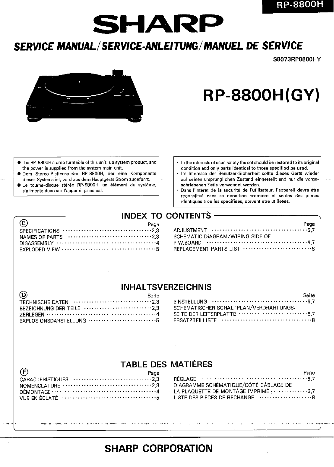
• The
RP-BBOOH
the power is supplied from the system main unit.
• Oem Stereo-Plattenspieler RP-8800H, der eine
dieses
• Le toume-dlsque stereo
Systems
s'alimente donesur l'appareil
®
SPECIFICATIONS
NAMES OF
DISASSEMBLY
EXPLODED
MANUAL/
stereo
turntable
let.wlrd ausdem HauptqeratStrom
PARTS
······································4
VIEW····································5
RP-8BOOH,
......••........••..•.......•••••
SERVICE.ANLEITUNG/
ofthisunitisa
un element du svsterne.
principal.
,
system
product,
Komponente
zugefOhrt.
and
• Inthe
condition and only parts identical to those specified be used.
· 1m Interesse der
auf seinen ursprunqlichen Zustand eingestellt und nur die vorge-
schriebenen
· Dans l'interet de la securlte de l'utllisateur, l'appareil devra etre
reccnstitue dans sa condition premiere et seules des pieces
identiques
INDEX TO CONTENTS
Page
'2,3
"2,3
ADJUSTMENT ,
SCHEMATICDIAGRAM/WIRING SIDE OF
P.w.BOARD
REPLACEMENT
MANUEL
DE
SERVICE
SB073RPBBOOHY
RP-8800H(GY)
interests
of user-safetythe setshouldberestoredto itsoriginal
Benutzer-Sicherheit sollte dieses Gerat
Teile
verwendet werden.
acelles specifieea, doivent etre utilisees.
-------------...
...•....•.....•.............
,.,..,
PARTS
L1ST·
wieder
Page
'6,7
'6,7
·8
INHALTSVERZEICHNIS
@ Seite
TECHNISCHE
BEZEICHNUNG
ZERLEGEN
EXPLOSIONSDARSTELLUNG
DATEN
DER
TEILE
········,····,····························4
··············,···········5
'2,3
"2,3
TABLE DES
C!)
CARACTERISTIQUES.•,
NOMENCLATURE·········,················,·,····
DEMONTAGE·,··········,····,·····,···············
EN
VUE
ECLATE
...,...•.........
• • 5
,.,
....•.
Page
'2,3
'2,3
·4
SHARP CORPORATION
EINSTELLUNG
SCHEMATISCHER
SEITE
DER
ERSATZTEILLISTE ,.., ·..· ·
.......•,......•
SCHALTPLAN/VERDRAHTUNGS-
LEITERPLATTE ,
".,
•. ,
MATII~RES
REGLAGE"....•........•.•.....•..•.•...•......
DIAGRAMME SCHEMATIQUE/COTE CA8LAGE DE
LA PLAQUETTE DE MONTAGE IMPRIME
L1STE
DES
PIECESDERECHANGE..· ·8
.,
.•....•.•..
Sette
'6,7
,,6,7
·•..· 8
Page
'6,7
'6,7
Page 2

FORACOMPLETE
REFER
TO THE
SPECIFICATIONS;
.
;P9WetsQLlt¢e.:'-:D~~:
Drive
system:
Speeds:
SiN
ratio: 60 dB IDIN-B)
WOW
and flutter: ± 0.2 %
Frequency.response:20 ,.20,000 Hz
Cartridge: j .'
Stylus pressure; 4 g
Effective length: 207 mm (B-5/32')
Replacement stylus: STY-155
Dimensions: Width; 430 mm (17')
Weight: 2.1 kg
DC 12 V supplied from main unit
Belt drive
33-1/3
MM
Height; 120 mm 14-7/8"1
Depth; 340 mm (13-7/16"1
system
and 45 rpm
(DIN
45 500)
cartridae (OART·155).
14.6
lbs.)
DESCRIPTION
OPERATION
OFTHE
MANUAL. .
OPERATION
OFTHIS UNIT,
PLEASE
-Specifications for
;,prim
notice.>
, ' .. '
1.17,
em
17~)
2. Turntable Platten
3. Centre Spindle
4. Tonearm
5. Tonearm Rest
6.Cartridge
7'.'Speed Selector Buttons
8. Cut Button
·CLi.
9.
1
a.Output
11. DC Supply Lead
Button:
Leads
this-modelaresubject
NAMES
'(0.;";
,;,j
j ,
EP
ReeordA\daptor
",:!'
to,change without
"I·
OF
..,.
..
1
PARTS
'I,
i J '
.,
, I' ..
"':i
~1""'=======~~1()
;}
)f
~
'ii
4,
,._.
"
7
8 9
CJ
,,'
. j
"~'
'.,
');
,
..
,.,
,
• Replacing
Whe~
the sound quality drops, replace the stylus
one
Ipart
No.
dealer},
Remove the
the.new
stylus.into.place as
the
stylus
PNDLDO
old
102AFZZ(STY-1551, consult ycmrSharp
stvlus by pulling it downwards gently, and push
~hQ~~
with
(£
a new
11
~Jr;
-.
,,·
:I ,
'>'
" J
~2-
(
~/""Di':
..:
Page 3
@
EINE VOLLSTANDIGE
DIESES
ENTHALTEN.
GERATES
BESCHREIBUNG
1ST
IN DER BEDIENUNGSANLEITUNG
DER
BEDIENUNG
®
POUR LA DESCRIPTION COMPLETE DU FONCTIONNEMENT DE CET APPAREIL, SE
D'EMPLDI.
REPORTER
AU MODE
TECHNISCHE DATEN
Spannungsversorgung:
Gleichspannung 12 V (gespeist vom
Hauptqeraf
Antriebssystem: Riemenantriebssystem
Drehzahlen:
Rauschabstand: 60 dB (DIN-B)
Gleichlaufschwankungen:
33-1/3
und 45
U/min
± 0,2 % (DIN45 500)
Frequenzgang: 20 - 20 000 Hz
Tonabnehmersystem:
Tonabnehmer mit bewegtem Magnet
(CART-155)
Aullagekraft:
Nutzlanqe:
Ersatznadel:
Abmessungen:
Gewicht:
Die technischen Daten
vorherige
AnkOndigung
4 9
207 mm
STY-155
Breite; 430 mm
Hohe: 120 mm
Tiele; 340 mm
2,1 kg
fOr
dieses Modell konnen ohne
Anderungen
unterworfensein.
BEZEICHNUNG DER TEILE
1. MittelstOck fur 17 cm EP-Schallplatten
groBem Mittelloch
2. Plattenteller
3. Mittelachse
4. Tonarm
5. Tonarmauflage
6. Tonabnehmersystem
7. Drehzahlwahltasten
8. Unterbrechungstaste
9. Tonarmlifttaste:
10. Ausgangsleitungen
11. Gleichstromzuleitung
:J[!:
mit
CARACTERISTIQUES
Alimentation: 12 V CC fourni par l'appareil principal
Svsterne d'entrainement:
Entrainement par courroie
Vitesses: 33
Rapport S/B: 60 dB (DIN-B)
Pleurage et scintillement:
1/3
et 45 tr
/mn
± 0.2 % (DIN 45 500)
Heponse en frequence:
20 - 20.000 Hz
Cellule: MM ICART·155)
Force d'appui: 4 9
Longueur utile:
Pointe de rechanqe: STY-155
Dimensions: Largeur;
Poids: 2,1 kg
Les caracteristiques de ce modele sont sujettes a modifi-
cation sans
preavis,
207
mm
Hauteur;
Profondeur;
430
120
mm
mm
340
mm
NOMENCLATURE
1. Adaptateur de disque45tours
2. Plateau
3. Axe central
4. Bras de
5. Hepose-bras
6. Cellule
7. Touches de vitesse
8. Touche de
9. Touche de leva-bras: :o:!:
10. Cordons de sortie
11. Cordon d'alimentation CC
lecture
rejet
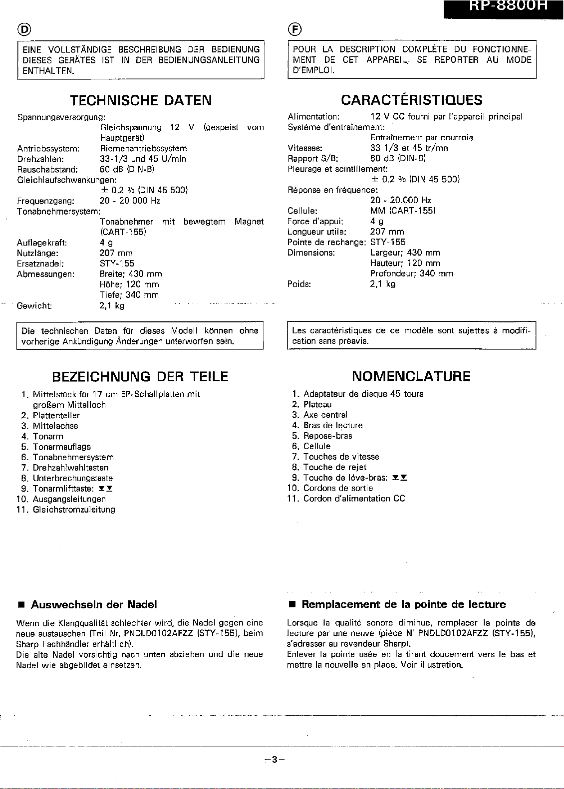
• Auswechseln der Nadel
Wenn
die Klanqcualitat schlechter wird, die Nadel gegen eine
neue austauschen (Teil Nr. PNDLD0102AFZZ (STY-155), beim
Sharp-FachMndler erhaltlich),
Die alte Nadel vorsichtig nach unten abziehen und die neue
wie
Nadel
abgebildet einsetzen.
• Remplacement de la pointe de lecture
Lorsque la qualite sonore diminue, remplacer la pointe de
lecture par une neuve (piece N' PNDLD0102AFZZ (STY-1551.
s'adresser au revendeur Sharp).
Enlever la pointe
mettre la nouvelle en place. Voir illustration.
usee en la tirant doucement vers Ie bas et
-3-
Page 4

®
::'-';"".:
g~.ujt,~~
roJlow
unlt_and rsassem
':',°""1.
pn
thebelow-mentioned rtoteswheri
DISASSEMBLY
......
-
....-.....•........
_._.':":.",,',','·.\.1
Dii.~as~~rri9Iy_;;:;'
_... __... -
/;:,:T::"J';:;TJ'''!
':
;:--'","\:-:;'"
-------_
..
- .. _--.----
:';c
7:'-"·'
..,
di'sClssert!oHn'g
01
in9_.Jt
JQ.
__
ke_~pJt~
J;;~f~_1Y
__
l;InJj'-
6xc;~II~ni.
performance:
1. Take record.
out,:~fthe:unit.:.
,"
__
,_,.
_
I"
2. Be sure to-'rerhbve'the'input/o'utput "plug-ft6m the audio
i:uli1it,beto"re :stiilrtiiigLto
3. Take off nylon bands or wire
disassemblethe
player: units'u
hclderswherethevneedbe
removed wbem'disassernblinq-the.unit, After servicing
the unit, be sure torearranqe the: leads
before disassembling.
STEP REMOVAL
1 Turntable 2.
Bottom
2
Board
@
Vorsichtsmassregeln
In::;:
:,.1
;,1;:1)
JJ~,
:,Ji(
.,:",1
>
,'le",
PROCEDURE,T)
Tur-fit~lJle;Ma'f'
1.
Sf6~:'rjng
Drive
3.
1.
Screw
i;j
~',:,
d
Fur
uo-.
".';::.
.....
Belt
,:,~i'ji
...
':"
"
: r
,~;J:
Das
.'
''-,,-,' 11
Z"rl\lg!"n
Beim Zerlegen und Zusammenbauen des
genden
heit
1. Schallplatte aus dem Gerat entfernen.
2
3.
Anweisunaen befolgen, um dessen
und ausgezeichnete Leistung aufrechtzuerhalten.
1
.:
I'Bevbr'
rrllt;dem
begonnen
stecker aus
Nylonbanderder
Zerlegen
ZerlegeHl'der :ScJ1a'll'pl'atre:rispielef'einneit
wird,
unbedingt
dem
Tonqerat ziehen.
den
Leitungshalter entfernen, falls dies
d@
/geiate$,~rf9rd~tliphii§~'i.
des Gerates darauf achten, die Leitungen
verleqen,
SCH-
RITT
1
2
®
Precautions pour Ie
wie
ENTEERNEN
Plattenteller
Bodenplatte
sie
vor
derl'Zerlegerl:ahgeoidtletVlareh.
VEREAHREN
1. Plattentellermatte
2. Stoppring
.....
3. Antriebsriemen
1.
Schraube
.......
"'
DEMONTAGE
dernorrtaqe
where
they-were-
I:
r',
ii
iii
'!~}
•.
,~",;'
...
'{A1)x1
;',.',,1
•••.
(A2)x1
(e·"····{A3):xl:
\U::
":'T."
'vmM
;_J
EIGUl\E
..
',j:~~!
il)
"7
'II"
Gerates die
Betriebssicher-
Ein'gangs-IAGsgarigs~
Nach Warten
......
:0"
•••..
.."
(A1)x 1
....
o'(A2}
••
'''~A3)
,
";-..,(B1')
wieder
,
';
x 1,
X1
x7
so
ABBIL'
DUNG
:-; '4'1
I
Lars du dernontaqe de I'appareil et de son remontage,
suivre les precautions ci-dessous, pour maintenir la securits
et d'excellentes performances.
1. Deposer la bande Ie disque de l'apparei
2. Ne pas
oublier
de
retirerlafiche
I.
d'entrse/sortle
unite d'acoustique avant de dernonter unite de tourne-
disqYr~"}'),"r)"
3. Deposer les bandes de - nylon ou les serre-cables si
I..
necessaire lors,du .dernontaqe .de l'appareil. ',Apres la
reparation.'Cfei::Vappa'reit;l s'assurer de, redisposer
tel qu'Ils staient avant Ie dernontaqet:
ETAPE
DEPOSE
Plateau
1
Plaque
2
de
base
,',
,"
..
,~i
,;,',
,,'
" , i~;
",,'
.':
);
PROCEDE
1. Feuille du plateau·
2. Contre-
bague
........
3. Courroie d'entralne
.................
1. Vis
T};T~"
..
",
)J!
.
~
,
"
.....
(A1)x 1
(A2)x1
....
(A3)x1
'(B1)
x7
;"..:-!
les'
FIGURE
4-1
4-2
,'_.
':::.,,,;
the
liii;
4-1
.;
"j'"
ii':
:;,1
,4;2
"jii
:':::'
fol-
beim
zu
,
4-2
du
fils'
-,--
'Ii J
, .
;--""
,
jJ\'
,:
TurntQp.le
:,
;_j".J
_' I',,: ;",;,"'.I!-:1!;'
,
1
I!'
'lo/
'J
il
Jr"
,~11
P
'J]
,~'
"',1
-,
,',
(~I)X1'~
03xl2mm'
,i, ,
~'!
~
'Bottom
'Sdard::}
'
.
•
,
".',
;
Figure
4-2
:.1,
1]-1"1,',
-4-
Page 5

A
2 -
B
3
46x3
"'t
5x3~
4
c
'
~
47
'0
'"
~
~
~----
'
~
~'
D
'~62
36
E
F
G
'<61
50
51
14x3
30
e e
,
14x2
13
L
"'./
:l
14x2
~
"
,'-
,
,
,
,
,
,
,
)
-,
t
,
H
2
Figure 5
EXPLOD"
-5-
4
EDVIEW
5
6
Page 6

ADJUSTMENT
A t Returnu 0
Jig
Test record
SSR-4005 adjusting screw Direction @: Early
. Rotational SpeedofPhono
Jig
Test record
SSR-4005
A
:
,y-;
,
Adju~til1g
Autoreturn Direction@: Late
Adjusting
Fig
6,2
CARTRIDGE
/'0".
:'
."
",
,
Point '
i
1--\
Motor
!
Pcirit
,
Specified'vetue
2.970 ± 10
r---+--_.---.
'QU1;PUT PWB-A
Remarks
Hz
:'';
Adjusting
Screw
Figure 6-1
'.
o
o
Figure 6-2
PGl
--
,-------,
PHONO
PLUG
OUTPUT
"L-CH
,~
i
B
C
o
R-CH
R-ch
.',
,:
-~~-----.
P:"LAYEF1UNI;r--·~--··-'··
S~~
SpEED '
33 45 SWI
o
iIIiiI
o
P P +
, ' ,
.'
--'
POWER"
----
._-~
~
1
I
DC
SUPPLY
+12V
GND
POWER
CORD
CNSl
Ml
E
L
__
,
2 3 If 5:
PHONO
MOTOR
Figure:
6'3
,SCHEMATIC DIAGRAM
-6-
I
I
~
6
Page 7

RP-8800H
@
.
Automatischer
Vorrichtung Einstellpunkt
TestschalJpJatte
SSR-4005
.
Drehzahl
Vorrichtung Einstellpunkt
Testschallplatte
SSR-4005
EINSTELLUNG
ROcklauf
Einstellschraube
fOr automatischen
ROcklauf
des
Plattenspielermotors
Abb
6-2
Bemerkungen
Richtung
®: Spat
Richtung @: Froh
Vorqeschrlebener Wert
2,970 ±
10Hz
PHONO OUTPUT PLUG
eo,
R-CH
REO
L-CH
WHITE
®
Retour
.
Automatique
REGLAGE
Dutil Point de reglage Remarques
Disque d'essai
SSR-4005 retour automatique
.
Vitessedumoteur
Vis de reglage de
phone
Direction
Direction ®: Rapide
Dutil Point de reglage Valeur speclflee
Disque d'essai
SSR-4005
Figure 6-2 2,970 ± 10 Hz
DC POWER SUPPLY CORD
eNSI
®: Lent
A
BK BK
B
SWI
POWER
GNO
0
BK
RO
C
33rpm
45rpm
WH
D
WH
.,
PHONO MOTOR
c 0
E
SW2
SPEED
,-c=33c-=-",.
...,..,.,-,.,-.--
SW'
CUE BUTTON
~~----
-----
------
:!:!
2
Figure7WIRING
SIDE DF
4 5 6
PW.BOARD
-7-
Page 8

®
REPLACEMENT
@
)u,,),ERSATZTEILLISTE
®
L1STEDES
"''"j
PIECES\
,
"pARTS
"flOW
'1'0
ORDElR
PARTS"
To have
borre~d.Y"
fhforrnatiOri:
your
order filled
plea~e-j~rnish
- - , -
LIST'
REPLACEMENT
promptly
-'ffie-fo.JJ_Q,WJ~g-:~~
:.<
, 1. MODEL NUMsER 'I·)",
2. REF.
NO,-'
3. PART NO.
4. DESCRIPTION
*MARK:
SPARE PARTS·DELIVERY SECTION
REF.NO.
CI
CNSI
MI
PGl
SWI
SW2
PART NO.
*
OTHER
VCKZPUIHFI02Z
9
9LULI
99LPA400!lJ,
99LUL2'6'74~W
9
9LLSB-1I23-46
99LTR2322229~
CIRCUITRY
007-2621"
,w,
J 1000pF,50V Ceramic
J Connector,DC
f.Phono
J'Plug
T'Switch,Leaf Type
«
'1
'.rSfitch,Push
..
SW3
I
2
3
4
5
6
6-1
6-2
6-3
6-4
7
7-1
7-2
7-3
7-4
8
9
11
12
13
14
15
16
17
18
19
20
22
23
24
25
99LSUF12-1
CABINET
99LPMIIOII
99LPP20010
99LPA30045
99LPP41230
99LPM30130
99LPA20090
. ,:)J'l'Vi!Ch,PUSh Type
PARTS
J 'Cabinet.Player
J
.Mat.Turntable
J :TurntabJe
JiBelt
J 'Arm.Actuator
J ITone,'Arrii Ass'y
'To~~:~r~(~?~
RCTRE51
PNDLDOI 0
99 LM2X8 LBK J
99LPA30020
99LPM20040
99 LPM4 00I 0
9
9LPP400
99LPM40080
99L+2S-3X20L;
99L+2S-2X6L
99LPM30120
99LPM41060
99 LPM41
99L+2S-3X8L
99LPM30090
99L+2-3XI2L
99LPZ40032
99LPZ400.61
99 LC.S.3 , J ,Stop Washer
99 LPM41
9999LLPpMZ44:00-00-3501'
99LPL40130
99LPM30061:
04AFZ~
2AFZ~
10
J :Cariridge(CART-155)
JStylus(ST\'~155)
J
Jill"a'
J.F'late,Clutch Guide
j,pi~te,Clutch
,J:St9Pper,C;!~tch!
J1Sciew,q13>O;20min
J
J'Arm,Gontrol"
Jtt.ttter.rcne Arm
070
J
J
J Arm,Control
J
'J,Spring,Control
JSpring,Tone
020'
:'J
J
')'Spdng,Lefter
4 Pin Locker
!.J,,-'\rm Stand
.ScreW,q12X8mm,Black
'Ge~r
,Screw,q1?>o;6mm
Lever
'Screw,~3X8mm
LeverLefter.
Lever.Swltcf
,,''I",.,'
)'i
:,r;
and -
t
PARTS
Supply Cord
CordPhono
!
[Power]
I
[SPEED]
Repfacement
f;ss!y
I
"BESTELLENyb.1\I
J
"J
;-i)WI11;ihrEln'-A~Wr~g
au~adnr~ri-:-;zu
!tlief91~~Qa:eTI.~ngjaben.
, '
'L
I '." ..•.. , .• " ...•
DESCRIPTION
-,
....
Powel-
Motor
Ass'y
Type
'',
MODELLNUMM~R
-2.-
REF;
NR ';;'
3. TElL NR.
4. BESCHREIBUNG
*MARKIERUNG:
,
Output
,
Item)
ERSATZTEILE·L1EFERUNG
CODE
AA
AQ
AZ
AW
AK
AS
[CUE]
AM
BE
AS
BB
AL
AE
BC
BA
AZ
IH"."·
AK
AB
'Ace
,j
Cue
Screw,q13XI2m"c,,~-"
Arm
Arm
Lifter
Lever
AD
AA
AA
AA
AE
AD
AB
AA
AC
"A
AC'
AC,
AA
JAD-
'AC
AC
AB
AD
'DERECHANGE,'\!
-',
" t'
~
ERS4TZTE!~~~'"
schnell und rlchtlg
':' I ')i" ,
kenhen, bitten wir urn
:
Ji\V
ifl ! 11
REF.NO.
26
27
28
29
30
31.
32 99LEG J Stop Washer,E Ring
33
34
36, "
37'
41
43
44·
45
46
47
49
50 99LPTOW3 J
51
52
53
54
55
57
,1'58
. 59
60
61
62 99LBK40.526, J Label,DC
A:
.
P.W.B.
F'WB~A
.-.'j
',.
PARTNO.
99LPM40150
99LPZ40030
99LPZ40033
99LPM41040
99LPA41010
,~,9.LPP31010
99LPM41050
99LRZ41030
99L+2S-3XI2L
9
9,LPM~
99,LPZ41010
99GPP,~1180
99LPL!40140
99Lp,P40020
99LRZ40010
9·9
LPM40
99LPZ40062
99L3.1
99LPM31021
·99
LPM31031
99LPM41031A
I
99[F'II141031B
'99,LPM310IlA
'9
9lPM310
'99LPM04'32
99LPK40595
99LPL47010
ACCESSQRIES/PACKING
99LPE41010
99LPE41020
99LPK40121
99LPK40131
99LPK40530!
99LPK405.n
99LPP20010
'i\SSEM:B~Y(I\l~t
I ,:'
99L912
UCOMMENrCOMMA~DEF{b~~'t;::;],<,
PIECES DE RECHANGE"
_..
--
-
"'
..
PO,urvoir y:?tre,
rh"a;'i~'r~~-;r~pide
"/
fournir)es,r~tlseigneriieri~s
.
.······i.'NUM~RO
C,\
' 2. N' DE REFERENCE
3.N"'DE-LAPIECE!
4. DESCRIPTION
*REMARQUE:
Pieces
derechange-Sectlon de livraison
*
J Locker
J
Spring
J Spring.Reject Lever
J Lever.Reject
J Center
J
Board,Bottom
J Holder,Switch
J Spring,Reject Lever
J Screw,
I 011 J Plate,Front
J
Rod.Cue
J Rubber,Foot
J Screw,Foot
J Cushion,
J Screw,¢J2.4X9mm
040
h B
i
c2
J EP Adaptor
J Spring,CUE/CUT Button
Washer,cjI3mm
J Terminal,Ground
J Foot,Right f;Q
J Foot,Left f;Q
} Bjrtton.Speed33rpm
J Button,Speed 45rpm
J Butlon,CUT
J Butlon,CUE
J Label,Motor
J LabeJ,Specifications
J Foot
J
Packing
J
Packing
J
Packing
Mat
J Polyethylene Bag,
Accessories
J Polyethylene Bag.Unlt
J
Packing
J
Mat,Turntable
Replacement
,:'
I;.~I
, J Output
"lu'.!
90rnrn<:l~(~ee,~~.cut,~e"
:'~f-
cb'rrecte,"
'[)ltMODELE.",~"
DESCRIPTION
Arm
Controller
Shaft
-sui'i~nts~.
Ass'y
de,
v~uT[ikizj
\1
"''''''''
'-c'1:):
CODE
AC
Arm
AB
AC
AD
AQ
A.R
A~
AD
¢J3
X
12mm
p
~A
As
i'Ei
~~
Motor
f;f\
J)B
Jt.A
AC
Ac
AA
AS
AE
AE
f;E
AE
AA
,
~
.•.
Ring
Input
PARTS
Add.,Front
Add.,Rear
Add.,Turntable
Case
~
~~
11'1
,N
f;U
AG
. I
, ,
1~
As
i !
I
Item)
!
I
!
,.....:
!
.
Writer
and Editor: Quality &
R~liabHity
Contra!
1/',
C~nter
of Audio
Systems
Group, Sharp Corp.
IA9008-5245NS . lSi· KI
Prtnted lnJapan
InJapan,g~drL!,c,~t--,
lmprime
au Japan
,
r!·
SG '
 Loading...