

Page 1
SHARP
SERVICE
MANUAL/
SERVICE.ANLEITUNG/
rpl1J
S;:~rrB1
GWVI7I1Ld/l
nMNC
,----------
-o(4S
AFs-E
!7FW
® Page
SPECiFiCATIONS··································
NAMESOF
DISASSEMBLY
ADJUSTMENT
PARTS
........••.....•........•.......
.....•.......•..•..................•
······································4
RCTRE
"Zx
INDEX TO CONTENTS
D
l.--~
cD
{02-
MANUEL
vtT
2-'&
DE
SERVICE
S78A1RP7700HK
S-Aol1lt'T2:t--
RP-7700H(BK)
qp
2,3
2.3
2,3
L?Au
f7
070fL
• In the interests of user-safety the set should be restoredto itsoriginal
condition and only parts identical to those specified be used.
· 1m Interesse der
auf semen ursprOnglichen Zustand elnaestellt und nur die Verge-
schriebenen Teile verwendet werden.
·
Dans
l'Interet de la secutite de l'utilisateur. l'appare!l devra
etre reconstitue dans sa condition premiere et seules des
iderrtiques acelles specifiees, doivent
SCHEMATIC DIAGRAM/WIRING
PW.BOARD
REPLACEMENT
EXPLODED
VIEW,
Benutzer-Sicherheit solite dieses Gerat
-------------,
········································4
PARTS
LIST
..........•..•...•......
90
tY1
NtuV
etre
utilisees.
SIDE
OF
.•.....................
fJv,
"
wieder
pieces
Page
'.5,6
···6
INHALTSVERZEICHNIS
@ Seite
TECHNISCHE
BEZEICHNUNG
ZERLEGEN
EINSTELLUNG
DATEN
...........•............................
•......••.................•...
DER
TEILE
.................•.•••..•.
.•.............•••..........•.•.••.•..
2,3
2,3
2,3
TABLE DES MATIERES
®
CARACTERISTIOUES
NOMENCLATURE··································
DEMONT
REGLAGE
AGE··
...........•.•
......•..•.•..............••..
....•....
_.'"......•....•••.•.••••.
-
..•......•....•...•.•....•.
Page
2,3
2 3
2:3
SHARP CORPORATION
SCHEMATISCHER
SEITE
DER
ERSATZTEILLISTE
4
EXPLOSIONSDARSTELLUNG
DIAGRAMME SCHEMATIOUE/CClTE CABLAGEDE
LA
PLAOUETTE
L1STE
VUE
DES
EN
ECLATE
4
SCHALTPLAN/VERDRAHTUNGS-
LEITERPLATTE····························4
PIECESDERECHANGE
........•.......................
··························6
DE MONTAGE
..•....•.
IMPRIME················4
_··························6
...........•.•...•
Seite
5,6
Page
5,6
Page 2
Power
source:'
Dimensions:
Weight:
Type:
Speed:
Motor:
Arm/cartridge:
Replacement
FOR A COMPLETE DESCRIPTION OF THE OPERATION OF THIS UNIT,
REFER
TO THE OPERATION MANUAL.
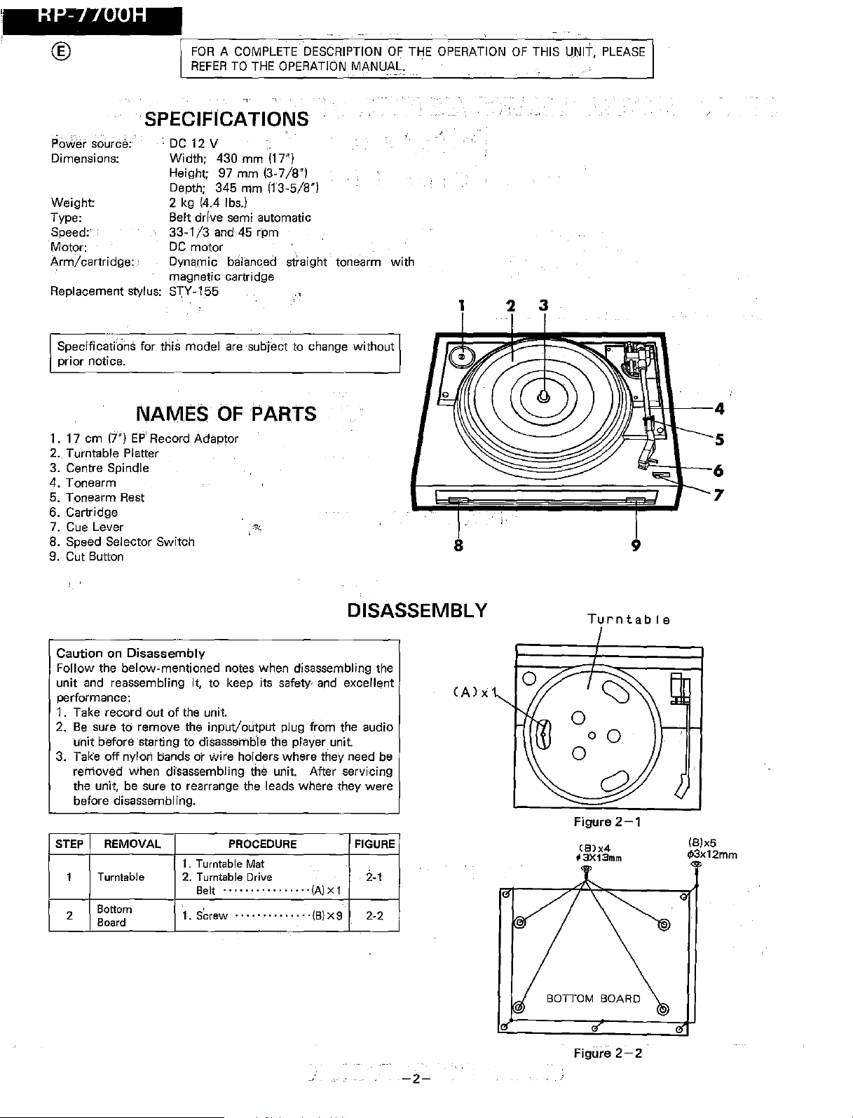
SPECIPICATIONS
, DC 12 V
Width;
Height; 97 mm (3-7/8")
Depth; 345
2 kg (4.4 lbs.)
Belt drfve semi automatic
33-1/3
DC
Dynamic balanced straight tonearm with
magnetic cartridge
stylus:
S"\Y-155
430 mm
and 45 rpm
motor
rnm
(1
r)
113-5/8")
PLEASE
1
3
2
Specifications for this model are
prior notice.
NAMES
1. 17 ern
17")
EP'
Record Adaptor
-subject
to change without
C>PPARTS
2. Turntable Platter
3. Centre Spindle
4. Tonearm
5. Tonearm Rest
6. Cartridge
7. Cue Lever
8. Speed Selector
Switch
~-".,;.
9. Cut Button
DISASSEMBLY
Caution on Disassembly
Follow the below-mentioned notes when disassembling the
unit and reassembling it, to keep its safety, and excellent
performance:
1. Take record out of the unit.
2. Be suretoremove the input/output plug from the audio
unit before Starting to dlsassemble the plaver unit.
3. Take off nylon bands or
removed when disassernbllnq the unit. After servicing
the unit, be sure to rearrange the leads where they
before disassembling.
STEP REMOVAL
Turntable
1
Bottom
2
Board
1.
Turntable
2.
Turntable
Belt
1.
S~rew
wire
holders where they need be
PROCEDURE
Mat
Drive
................
..............
(AIX 1
(B)
X 9
were
FIGURE
2-1
2-2
8
(Alx
Turntable
o
00
o
Figure
(S)x4
tl3X13mm
1/1
JF1!F!\--I--4
""'=:::::-1--6
9
2-1
IBlx5
.p3x12mm
5
7
-2~
BOTTOM BOARD
Figure
2-2
Page 3

RP-7700H
REF.NO.
443
443
447
449
452
453
454
455
456
701
702
703
704
706
707
A
PART
NO.
99LPK40491
99LPK40492
99LPK40550
99LPK40521
LHLDW1124AFZZ
99LPM402BO
99LPM40560
99LPP40520
99LPZ403BO
99LC.S.3
99L+2S-2.6XBL
99L+2S-2XL6
99L+2S-3X20L
99L+2S-3X4L
99LPZ40010
1 2
Adj.
COOE
AS
AS
AA
AA
AC
AD
AD
AD
AA
AA
AA
AA
AA
AA
3
OESCRIPTION
Label.Specifications
La
bel,
Specificat
[West Germany Only]
Label,Motor
Label Phono Output Plug AS
Nylon
Band,BOmm
Lever,Cue
Lever,Cue
Rod,Cue
Spring,Cue
Stop Washer
Screw
rt,b2.6X8mm
Screw,q,2X
Screw,eP3x
Screw,rP3X
Screw,r/12.4X9mm
ions
Speed
Knob
6mm
20mm
4mm
REF.NO.
709
710
713
714
715
4
PART
NO.
99LM3XI2L
99L+2S-3XI2L
99LPL40140
99L+2S-3XLB
99LToW3
PACKING PARTS
99LPK404BO
99LPK40530
99LPK40531
99LPK40532
99LPK40540
99LPZI0II0
99LPZI0120
OESCRIPTION
Screw,t,b3X
Screw,r/13X12mm
Screw,Foot
Screw,r/J3XBmm
Toothed Washer
Polyethylene Bag,
Turntable
Polyethylene Bag,Unit
Packing Case
Packing Case [West
Germany
12mm
Only]
Pad
Packing
Packing Add. Rear
Add.
Front
5 6
CODE
AA
AA
AA
AA
AA
AC
AD
AK
AK
AS
AE
AE
A
B
C
fr
714xa
0
"5
E
B
C
o
E
1
Writer
2
Figure 6 EXPLODED VIEW
and Editor: Quality & Reliability Control Center of Audio Systems
___________________
Group,
Sharp Corp.
6
-1
ASSOS'S227NS
PrintedinJapan
In
Japan
lniprimeau"""Japon
SG·
SS
·HA·
gedruckt
-.-------
K'I-
Page 4

RP-7700H
@
EINE VOLLSTANOIGE BESCHREIBUNG DER BEDIENUNG
DIESES GERATES 1ST IN DER BEDiENUNGSANLEITUNG
ENTHALTEN,
, ,
.
TECHNISCHE DATEN
Spannungsversorgung:
Gleichspannurtq 12 V
Abmessungen:
Gewicht: 2 kg,
Typ:
Drehzahl: 33-113 und 45
Motor: Gleichstromrnotor
Tonarm/-abnehm'er: Dvnernisch
Ersatznadel:
DiJ technischen Daten fur dieses Modell konoen ohne
vorherige
AnkOndigung
Breite; 430 mm
HOhe;97mm
Tiefe;
345
mm
Rieme:nantrieb,
halbautomatisch
U/min
balancierter
mit Magnettonabnehmer
STY-155
Anderungen
unterworfen
gerader Tonarm
aetn.
®
POUR LA DESCRIPTION.GOMPLETE
MENT DE CET APPAREIL, SE REPORTER AU MODE
D'EMPLOI..
.•.........
:.., -
. •
D~
FONCTIONNE-
CARACTERISTlciUES.
Alimentation:
Dimensions: La'rgeur;'
Poids: 2 kg
Type: Entrainement par courroie, semi-automa-
Vitesse: 33 113 et 45 tr
Moteur: Moteur
Bras/cellule; Bras
Pointe de
Les caracteristiques de de modele sont sujettes a modifi-
cation sans
rechanpe: STY-
preavis,
12\/
CC··
430
mm
Hauteur:
Profondeur;
tique
97
mm
345
mm
Imn
CC
direct
a equilibraqe dynamique
avec cellule rnaqnetique
155
BEZEICHNUNG DER TEILE
1.
Mittelstock
Mitteiloch
2. Plattenteller
3.
Mittelachse
fOr
17cm
4. Tonarm
5.
Tonarmauflage
6. Tonabnehmersystem
7. T
onarmlifthebel
8. Drehzahl-Wahlschalter
9. Unterbrechungstaste
ZERLEGEN
Vorsichtsmassregeln
Bairn
Zerlegen
genden Anweisungen
heit
und
ausgezeichnete Leistung aufrechtzuerhalten.
1.
Schallplatte
2. Bevor
begonnen
stecker aus
3.
Nvlonbanderder
Zerleqen
des
Gerates darauf achten, die Leitungen
verlegen,
und Zusammenbauen des Gerates die fol-
aus
dem
mit
dem
Zerlegen del' Schallplattenspielereinheit
wlrd, unbedinqt den Eingangs-/Ausgangs-
dem Tonaerat ziehen.
Leitungshalter entfernen,
des Geratss erforderlich ist. Nach Warten
wie
sie vor den Zerlegen angeordnet waren.
EP-Schallplatten
FOr
Das Zerlegen
befolqen, urn dessen Betriebssicher-
Gerat entfernen,
mit
falls
wieder
grol!.em
dies
beirn
so zu
NOMENCLATURE
1. Adaptateur de disque 45
2. Plateau
3. Axe central
4. Bras de lecture
5. Repose-bras
6.
Cellule
7. Levier de leve-bras
8. Selecteur
9. Touche de
de vitesse
rejet
tours
DEMONTAGE
Precautions pour Ie
Lars du dernontaqe de l'appareil et de son remontage,
sulvre
les precautions ci-dessous, pour maintenir la securite
et d'excellentes performances.
1. Deposer la bande Ie disque de
2. Ne pas oublier de retirer la fiche d'entrea/sortie du unite
d'acoustique avantde
3. Deposer les bandes de nylon ou les serre-cables si
necessaire lors du dernontaqe de l'appareil. Apres la
reparation de
tel qu'ils
etaient avant Ie dernontape.
dernontaqe
l'appareil,
dernontsr
l'appereit, s'assurer de redisposer les fils
unite de tournedisques.
SCH-
ENTFERNEN
RITT DUNG
Platten- 1. Plattentellermatte 2-1
teller 2. Plattenteller-
1
2 Boden-
platte
1. Schraube
VERFAHREN
Antriebsriemen
............
....
"(A)X1
(B)x 9
ABBIL-
2-2
ETAPE DEPOSE PROCEDE
1 Plateau
2 Plaque
1. Feuille du plateau 2-1
2. Courroie d' entraine-
rnent du
1'; Vis
debase
-3-
plateau·····
. ,
.........•
'{Al x 1
····(B)X9
FIGURE
2'2
Page 5

®
REPLACEMENT
@
ERSATZTEILLISTE
®
L1STE
RP-7700H
I
DES
PIECES
PARTS LIST
"HOW TO
To have your order filled promptly and
correctly, please furnish the following
information.
REF.NO.
IC601
L1
There are two types of capacitors available and they can be identified
other by reading their Part Numbers.
• Ceramic
A symbol "C" or
K)····"J."
• Semiconductor type capacitor:
A symbol
The capacitance error of each capacitor is indicated by the symbol given at the
13thdigit of the Part Number as follows;"J"
"N"
(±30%), "C"
(Tubular type ceramic capacitor is identified by the symbol TV(TQ/CY) of the
part NO.
(Tubular type ceramic capacitor is identified by the symbol MF(MN) of the
NO.
VCOOMF(MN)OOOOOOO;
Unless otherwise specified, electrolytic capacitors are
C1
C2
C601,602
C603
C604,605
C606,607
C60S,609
C610,611
C612,613
C614
C615,616
C617,618
C619
(Unless otherwise specfifed, resistors are ±5%,carbon type.)
R601,602
R603-606
R607
R608-611
R612,613
Bill.m
R616,617
R618,619
R620,621
ORDER
REPLACEMENT
PARTS"
1. MODEL NUMBER
2. REF. NO.
3. PART NO.
4. DESCRIPTION
PARTNO.
INTEGRATED
VHiBA715///-1
COIL
VP-CH471KOOOO
CAPACITORS
type
capacitor;
"K"
is given at the 3rd digit of its Part Number like
"T'
is given at the 3rd digit of its Part Number like "VCT ..
(±0.25
pF),
"0"
(±0.5
VCOOTV(TQ/CY)OOOOOOO;
RC-GZA336AF1C
VCKZPU1HF103Z
RC-GZA105AF1H
RC-GZA476AF1C
VCCSPA1HL221J
RC-GZA475AF1C
VCQYKA1HM222J
VCQYKA1HM822J
RC-GZA335AF1H
RC-GZA476AF1C
VCCSPU1HL471K 470pF,50V
VCCSPU1HLl01K
VCKZPU1HF223Z
VRD-ST2CD471J
VRD-ST2CD104J
VRD-ST2EE331J
VRD-ST2CD102J
VRD-ST2CD333J
VRD-ST2CD394J
VRD~-ST2C5-124J
VRD-ST2CD102J
VRD-ST2CD1D2J
-----_.-
this TV(TQ/CY) does not meanthe lead wire.)
this MF(MN) does not mean the lead wlre.)
RESISTORS
-
DESCRIPTION
CIRCUIT
Equalizer Amp.,BA715
470
"H
(±5%),
"K"
pF),"Z"
(+80-20%).
33 "F,16V
0.01
"F
1
pF,50V,Electrolytic
47 "F,16V,Electrolytic
220 pF
4.7"F,16V,Electrolytic
0.0022
"F
0.0082
"F
3.3
pF,50V,Electrolytic
47 "F,16V,Electrolytic
100pF,50V
0.022
"F,50V
470 ohms,1/6W
100 kohm,1/6W
330ohms,!/4W
1
kohm,!/6W
33 kohms,
390 kohms,1/6W
rtO~kohms)76W
1
!/6W
kohm,!/6W
! kQhm,1/6W
"BESTELLEN VON ERSATZTEILEN"
Urn Ihren Auftrag schnell und richtig
ausfOhrenzukormen,
diefolgenden Angaben.
1. MODELLNUMMER
2. REF. NR.
3. TElL NR.
4. BESCHREIBUNG
CODE
AD
AB
from
each
"vce
····J:'
(±10%),
"M"
(±20%),
part
±20%
type.
AB
AA
AB
AB
AA
AB
AB
AB
AB
AB
AA
AA
AA
AA
AA
AA
AA
AA
AA
KA--
AA
-
--.-.,..,...,.,---.
AA
bitten wir urn
REF.NO.
CNS601
M601
PG601
SW601
SW602
401
402
403
(or
404
405
406
408
409
410
411
412
413
414
414 1
414-2
414-3
414-4
415
416
417
418
420
422
423
425
426
42 -1
426-2
426-3
426-4
427
428
429
430
432
435
436
437
440--
442 QHWS-OOOICEFN
-~.,.,..,,~---,-
--,.,.
__
99LULlO07
99LPA40080
99LULAWM2863
99LLSB-1l23
99LSUF12
99LPM10070
99LPM40190
99LPZ40020
99LPP30031
99LPM40550
99L3
99LPM40070
99LPZ40031
99LPA40020
99LPM30120
99LPZ40030
99LPM30130
99LPA30020
99LPM20040
99LPM40010
99LPP40010
99LPM40080
99LPM40050
99LPZ40110
99LPM40170
99LPZ40033
99LPM30100
99LPM40160
99LPP40020
99LPM40090
99LPA20090
RCTRE5104AFZZ
PNDLD0102AFZZ
99LM2X8LBK
99LPM30090
99LPZ40032
99LPM40240
99LPP30020
99LPP40180
99LPM20070
99LPP40230
99LPP20010
99~PM40030~~--
._._~._-_.-
PART NO.
OTHER
PLAYER
.1X12XO.8
DE RECHANGE
"COMMENT
PIECES DE RECHANGE"
Pour
voir
manlere rapide at correcte, veuillez
fournir les renseignements suivants.
1. NUMERO DU MODELE
2. N' DE
3. N' DE LA PIECE
4. DESCRIPTION
CIRCUITRY
MECHANISM
COMMANDER DES
votre
commande executee de
REFERENCE
DESCRIPTION
PARTS
DC
Power
Supply Cord
Phono
Motor
Plug
[Phcno
with PUlley
Output]
Switch,Leaf Type
Switch.Push Type
[Turntable
PARTS
Speed]
Cabinet,Player
Ufter,Tone
Spring,Tone
Plate,
Lever,Cue
Cabinet
Arm
Arm
Lifter
Stopper.washer
Lever,Lifter
Spring,Lifter
Center
Arm,Controler
Spring,Controler
Arm,Actuator
Gear
Gear
Plate.Clutch
Plate,Clutch
Stopper,
Lever,Switch
Link,Reject
Lever,Reject
Spring,
Button,
Cut
Holder,Reject
Cushion,Motor
Lock
Tone
Tone
Cartridge
Stylus(STy
Screw,
Arm,Controt
Spring,Control
Holder,Power
Board,Bottom
Rubber,Foot
Turntable
Belt,Turntable
Mat,
Turntable
EPeAdapter - A-Q
Earth
Lever
Shaft
Ass'y
Ass'y
Guide
Clutch
Lever
Reject
Lever
Turntable
Lever
Lever,Tone
Arm
Ass'y
Arm
C155)
012
X
Bmm,
Supply
Lug
Arm
Speed/
Link
Arm
Black
Arm
Cord
CODE
AQ
AZ
AP
AK
AL
BB
AC
AC
AD
AC
AC
AC
AC
AS
AE
AC
AE
AK
AB
AC
AD
AA
AC
AP
AD
AC
AC
AB
AB
AB
BC
BA
AZ
AA
AD
AC
AB
AN
AD
BC
A L
AS
AA
-5-
Page 6

RP-7700H
®
·
Auto
Return
Jig
Test record
SSR-4005
·
Rotational
,
~ig
Test record
SSR-4005
@
·
Automatis'cher'RQcklauf
Vorrichtung
Testschallplatte
SSR.4005
ADJUSTMENT
,
Adjusting- Point
Auto return
adiustinascrew,
Speedoff'hohO MOtor
'"
AqJl,lsting
Point
, Fig4-2 2,970 ±
"
EINSTELLUNG
Eil'i'stelJpunkt
EinsteJ
lschraube
fOr'autcrttatischen
Buckjauf
· Drehzahl des Plattenspielermotors»
Vorrichtung
Testschallplatte
SSR-4005
., I
Einstellpunkt
Abb 4-2
•
®
·
Retour
Outil
Disque d'essal
SSR-4005
Automatique
REGLAGE
,
Point de fl§glage
Vis de reglage de
retour 'automatique
Remarks
Direction..@: Late
Dir~ction@:
Specified value
10Hz
Bemerkungen
Hlchtunq @: Spat
Ricl;ltung@:
Vorgeschriebener Wert
'2,970±10Hz
,
,
Remarques
Direction @: Lent
Direction @: Hapide
1:8tly
fruh
. SPEED "ADcl
nn
- + - +
45rpm 33rpm
FRONT sros
"
'.
Adjusting
Screw
Figure
4-'
BOTTOM BOARD
@
@i"'
@
Figure 4-2
CARTRIDGE
{D~-
POWER
C2
51'1601
?
'"
=4d~~-1
o
'"
MOTOR
ALACK
MGOI
r--=---j_-~:;-=
BLACK
·
Vitessedurnoteur
Outil
Disque d'easel
SSR-4005
N
phone
Point de reglage
.
Figure
4-2
PLAYER UNIT
L'hL'
Valeur apecifiee
2,970
..
R601 CSOI
470
C616
470P
± 10 Hz
1/50V
R60S
lOOK
RGOe
lOOK
'50'
"
C603+
47/1SV
R604
lOOK
R607
'"
"
000'
220P
U
470pH
• '
~o:t!J
..
[:::1.
51'1602
SPEED
~3rpm.
4srpm
~
Figure 4-3
le601 BA71S EO
RGI5
390K
R611 R621
IK IK
+C607
4.7/16V
000'
+4.71ISV
RSIO
I K
'-'1I_~rJ47/IGV
C609
C611
0.0022
0,0082
C608
CGIO
0.0022
R620
IK
0.0082
ca
0.01
"
AMP.
CSI4
•
, C61Z
3.3/50V
CI.
j
~
WIRING
R617
120K
RGIS
120K'
SIDE OF P. W. BOARD
o LSOI
o ImH
CSI7,
lOOP. "
C618
lOOP
aere
IK
+12V'
REO WHITE
R-ch
OUTPUT
PG601
L'ch
Figure 4-4 SCHEMATIC DIAGRAM
-4-
 Loading...