

Page 1
INSTALLATION INSTRUCTIONS
For Sharp Carousel® Built-in Kit
Models RK94S27F or RK94S30F
S = STAINLESS
THIS KIT IS UL APPROVED TO ALLOW CERTAIN MICROWAVE
OVENS TO BE INSTALLED ABOVE ANY ELECTRIC WALL OVEN.
PLEASE SEE THE OPERATION MANUAL REGARDING APPROVED
BUILT-IN APPLICATIONS.
IMPORTANT:
This Built-in Kit is designed for and approved only for those
Sharp Microwave Ovens specifying Built-In Kit RK94S27F or
RK94S30F. Refer to Operation Manual for approved models.
IMPORTANT NOTES TO THE INSTALLER
• PLEASE READ THESE INSTRUCTIONS THOROUGHLY
BEFORE BEGINNING INSTALLATION.
• Observe all governing codes, ordinances, and safety
instructions.
• Be sure to leave these instructions with the consumer.
• Be sure to DISCONNECT THE PLUG of the microwave
oven from the electrical outlet before installing the Built-in
Kit. Remove the Carousel turntable from the oven cavity.
• Because the kit includes metal parts, due caution should
be used in handling and installation to avoid the possibility
of injury.
ITEM PART NAME QTY
ITEM PART NAME QTY
FRONT FRAME
J
RK94S27F: FDECAB229MRK0
RK94S30F: FDECAB227MRK0
BACK FRAME
K
RK94S27F: FDECAB255MRK0
RK94S30F: FDECAB226MRK0
AIR DEFLECTOR
L
RK94S27F: PREF-B038MRP0
RK94S30F: PREF-B039MRP0
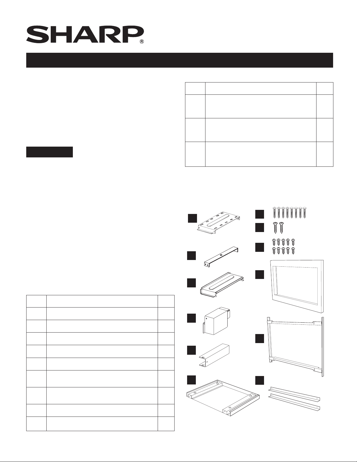
Check list for parts when unpacking.
NOTE: (J) FRONT FRAME and (K) BACK FRAME are shipped
attached. Snap apart before installation.
A
DUCT (A)-1
G
H
1
1
2
I
B
DUCT (A)-2
J
C
DUCT (A)-3
A DUCT (A)-1: PDUC-0259WRW0 1
B DUCT (A)-2: PDUC-B127MRP0 1
C DUCT (A)-3: PDUC-A734WRW0 1
D DUCT (B): PDUC-0260WRW0 1
E DUCT (C): PDUC-A274WRW0 1
BOTTOM DUCT ASSEMBLY:
F
FDUC-B099MRK1A
M3.9-16MM PAN HEAD TAPPING
G
SCREW, ZINC: XOPS740P16000
H WOOD SCREW: XTSS740P20000 2
I CABINET SCREW: XOTS740P12000 10
D
DUCT (B)
K
E
DUCT (C)
1
8
E 1
F
L
Page 2
STANDARD INSTALLATION INSTRUCTIONS
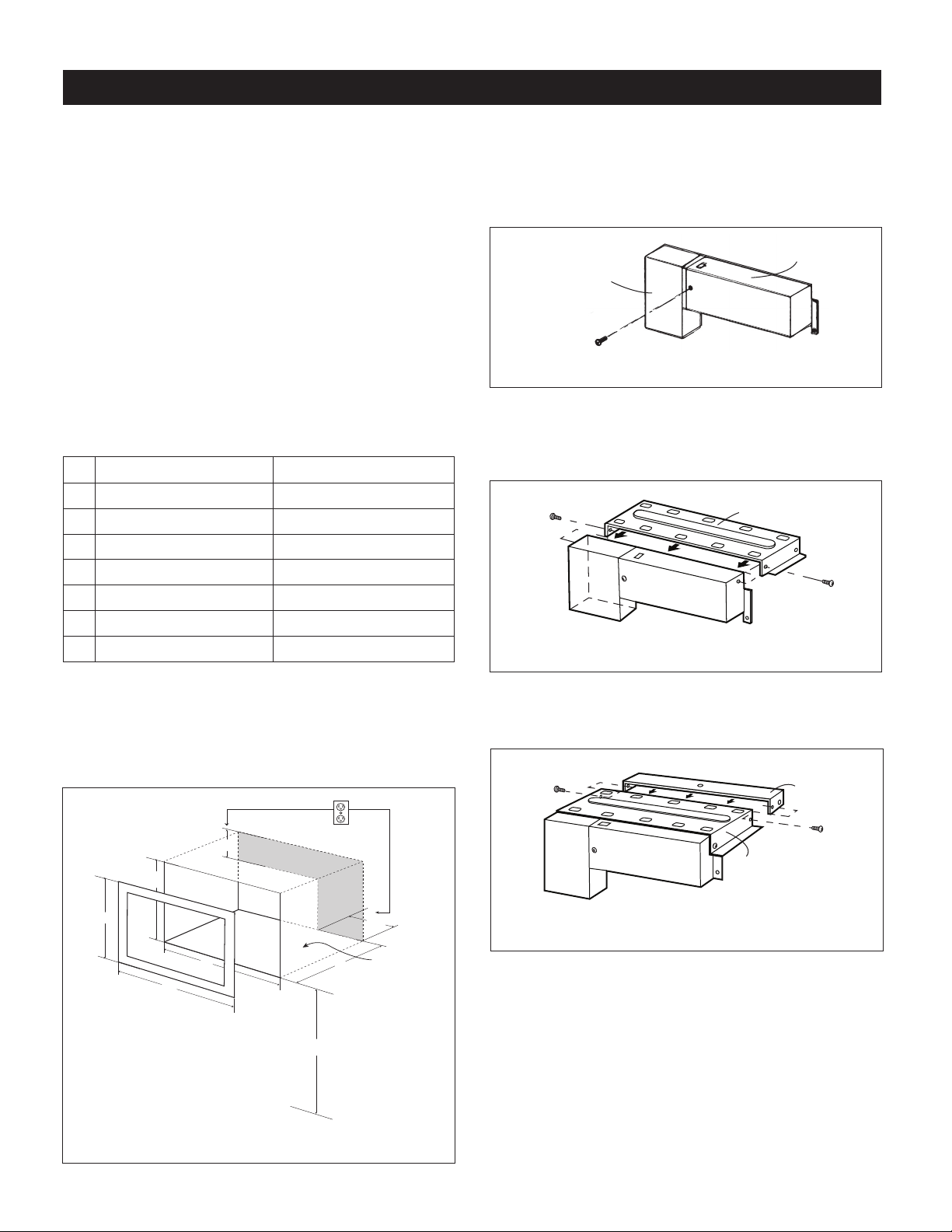
STEP 1 - CABINET OR WALL OPENING
Provide an opening in the wall or cabinet as indicated
in Figure 1. The depth should be a minimum of 20 1/8"
(511.2 mm). If the Depth (E) dimension is greater than 21"
(533.4 mm), the outlet location may be in any area on the
rear wall. The oor of the opening should be constructed of
plywood strong enough to support the weight of the oven
(approximately 100 lbs/45 kg) and should be level for proper
operation of the oven.
NOTE: While the proper function of the oven does not
require that the opening be enclosed (with sides, ceiling and
rear partition), this may be required by local code, and it
is suggested that the local code be checked for any such
requirement.
The opening in the wall or cabinet must be within the
following dimensions, centered horizontal to the cabinet.
RK94S27F RK94S30F
A 20" (508 mm) 20" (508 mm)
7
B 26
C 18
D 25
E Min. 20
F 5" (127 mm) 5" (127 mm)
G 10" (254 mm) 10" (254 mm)
/8" (682.6 mm) 29 7/8" (758.8 mm)
1
/2" (470 mm) 18 1/2" (470 mm)
1
/4" (641.3 mm) 25 1/4" (641.3 mm)
1
/8" (511.2 mm) Min. 20 1/8" (511.2 mm)
STEP 2 - EXHAUST DUCT ASSEMBLY INSTALLATION
A. Insert the edge of DUCT (B) into the hold lip of DUCT (C).
Secure together by using a SCREW (I) provided in the kit.
See Figure 2.
DUCT (B)
SCREW (I)
FIGURE 2
B. Position DUCT (A)-1 on the top of the oven inserting
edge of DUCT (BC) assembly into hole lip of DUCT (A)-
1. Tighten 2 SCREWS (I), securing DUCT (A)-1 to DUCT
(BC) assembly. See Figure 3.
SCREW (I)
DUCT (BC)
FIGURE 3
DUCT (C)
DUCT (A)-1
SCREW (I)
Outlet should NOT be in the shaded area as indicated on
Figure 1.
NOTE:
• If the dimension of DEPTH (E) is more than 21" (533.4 mm),
the outlet location may be any area on the rear wall.
F
C
A
D
B
NOTE: Floor of opening
should be 90˚ to front
34-1/2” MIN.
G
FLOOR
E
cabinet frame.
FLOOR
C. Position DUCT (A)-2 on the top of the oven and insert it
into the hold lip of DUCT (A)-1. Secure DUCT (A)-2 to
DUCT (A)-1 using 2 SCREWS (I) provided. See Figure 4.
SCREW (I)
DUCT (A)-1
DUCT (A)-2
SCREW (I)
FIGURE 4
FIGURE 1
E 2
Page 3
STANDARD INSTALLATION INSTRUCTIONS
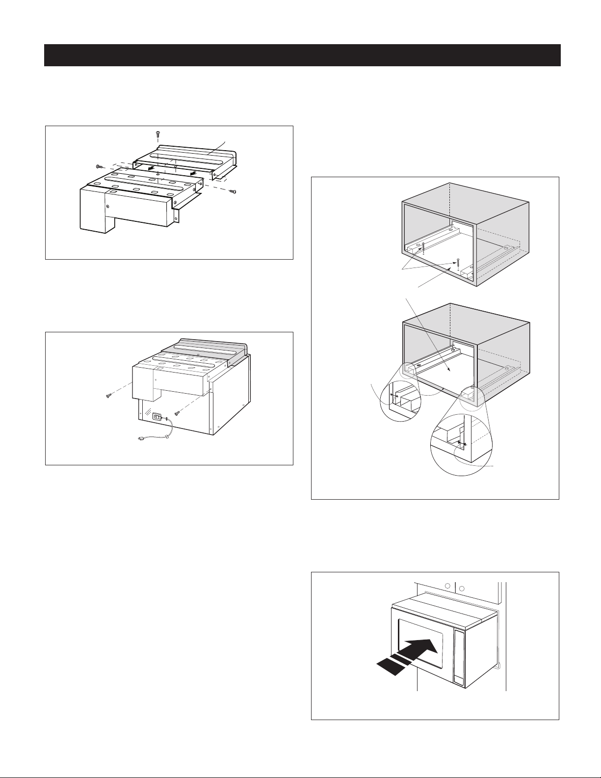
D. Position DUCT (A)-3 on top of the oven and insert it into
DUCT (A)-2. Secure DUCT (A)-3 using 3 SCREWS (I)
provided. See Figure 5.
SCREW (I)
SCREW (I)
DUCT (A)-3
SCREW (I)
DUCT (A)-2
FIGURE 5
E. Remove SCREWS from the upper right and left corners
at the rear of the oven. Place duct assembly on the top
of the unit as shown and secure the duct assembly to the
oven using the 2 SCREWS just removed from the oven.
See Figure 5A.
STEP 3 - SURFACE INSTALLATION
A. BOTTOM DUCT ASSEMBLY: Place the Bottom duct in
the center of the opening so that gap "A" is equal to gap
"B". When the BOTTOM DUCT ASSEMBLY is positioned
properly, the front edge of the duct will be ush with the
front of the cabinet. Secure with 2 SCREWS (H) See
Figure 6.
SCREW (H)
BOTTOM DUCT ASSEMBLY
SCREW
SCREW
FIGURE 5A
GA P "A"
NOTE:
CENTER BOTTOM
DUCT ASSEMBLY IN
THE OPENING
DETAIL A
GAP "B"
FIGURE 6
B. CABINET INSTALLATION: Place the oven adjacent to
the wall or cabinet opening. Plug the power cord into the
electrical outlet. Carefully guide the assembled oven into
the prepared opening. Slide the oven on the BOTTOM
DUCT ASSEMBLY. See Figure 7.
E 3
FIGURE 7
Page 4
STANDARD INSTALLATION INSTRUCTIONS
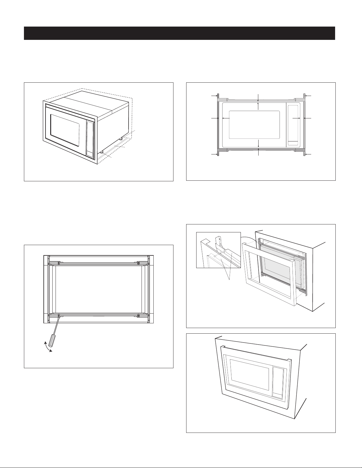
C. CABINET INSTALLATION: Avoid pinching the cord
between the oven and the wall. Adjust the position of the
oven so that the feet of the oven are tted into the holes
of the BOTTOM DUCT ASSEMBLY. See Figure 8.
FOOT
BOTTOM DUCT
ASSEMBLY
DUCT RECESS
FIGURE 8
D. DISASSEMBLY: The FRONT FRAME and BACK FRAME
come pre-assembled with ball studs engaged in the
receivers. Separate the FRONT FRAME from the BACK
FRAME. Place the assembly facedown on a protected
surface. At the location of the ball stud, insert a athead
screwdriver between the FRONT FRAME and the BACK
FRAME and gently pry up to disengage the ball stud from
the receiver. Repeat for each corner. See Figure 9.
E. BACK FRAME INSTALLATION: Position BACK FRAME
equal space top to bottom, side to side. Mark for 4 holes,
1
center punch and pre-drill with
/16" drill bit. Secure
frame with 4 SCREWS (G). See Figure 10.
MOUNTING HOLES
EQUAL GAP
SIDE TO SIDE
MOUNTING HOLES
EQUAL GAP TOP, BOTTOM
MOUNTING HOLES
MOUNTING HOLES
FIGURE 10
F. FRONT FRAME INSTALLATION: Place the FRONT FRAME
onto the BACK FRAME and align ball studs and receivers.
Secure the FRONT FRAME to the BACK FRAME by rmly
pushing the FRONT FRAME onto the BACK FRAME,
engaging the 4 snap attachments. See Figures 11-12.
FIGURE 9
SNAP
ATTACHMENT
FIGURE 11
FIGURE 12
E 4
Page 5
FLUSH INSTALLATION INSTRUCTIONS
(76 MM)
STEP 1 - CABINET OR WALL OPENING
The opening in the wall or cabinet must be within the
following dimensions:
OPENING RK94S27F RK94S30F
1
A 25
Width (B) 27
Height (C) 22
D 1" (25.4 mm) 2
E 2
F 1
G 5" (127 mm) 5" (127 mm)
Minimum
Depth (I)
Outlet should NOT be in the shaded area H as indicated in
Figure 1.
E
/8" (638.2 mm) 25 1/8" (638.2 mm)
1
/8" (689 mm) 30 1/8" (765.2 mm)
7
/16" (569.9 mm) 22 7/16" (569.9 mm)
1
/2" (63.5 mm)
1
/8" (54 mm) 2 1/8" (54 mm)
1
/2" (38.8 mm) 1 1/2" (38.8 mm)
20" (508 mm) 20" (508 mm)
Top View
A
B
Front View
D D
Shelf
Bottom of flush cutout
Mounting
cleat
Shelf
F
G
C
B
Cabinet
face
H
G
I
NOTE:
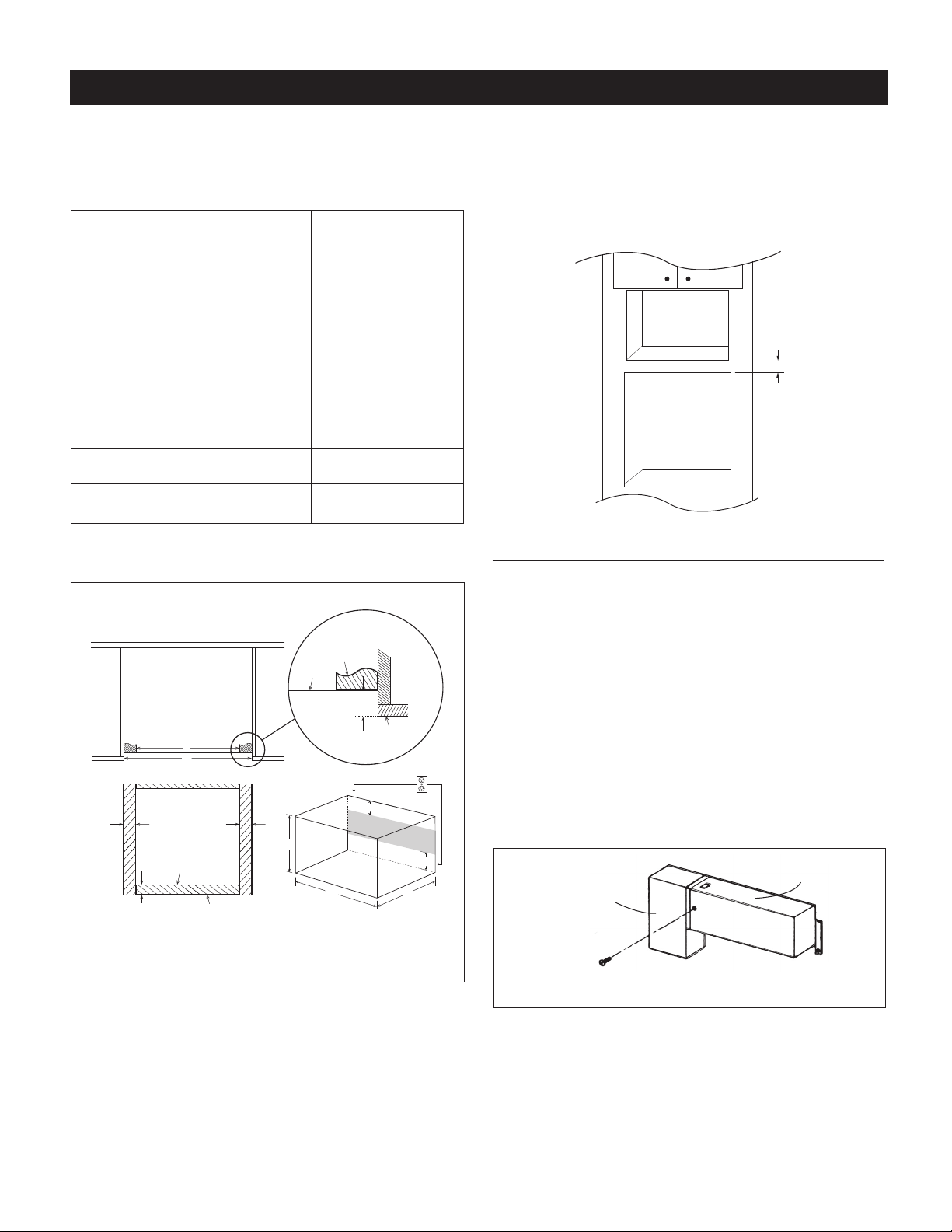
• Please allow minimum 3" (76 mm) wood gap between the
microwave oven cutout and the appliance cutout below
the microwave oven. See Figure 2.
Microwave cutout
3"
Wall oven cutout
Min.
FIGURE 2
• The oor of the opening should be constructed of
plywood strong enough to support the weight of the oven
and oor load (approximately 100 pounds/45 kg). The
oor should be level and 90˚ with the face of the cabinet
for proper installation and operation of the oven. Be sure
to check the local building code as it may require that the
opening be enclosed with sides, ceiling and rear partition.
The proper functioning of the oven does not require the
enclosure.
STEP 2 - EXHAUST DUCT ASSEMBLY INSTALLATION
A. Insert the edge of DUCT (B) into the hold lip of DUCT (C).
Secure together by using a SCREW (I) provided in the kit.
See Figure 3.
DUCT (B)
DUCT (C)
FIGURE 1
NOTE:
Dimension C above will result in 1
1
⁄4" (31.8 mm) spaces
above and below the trim to allow for necessary intake and
exhaust air ow to ensure appliance does not overheat. Do
not reduce this spacing as doing so will void the warranty
for any issues resulting from a lack of airow.
SCREW (I)
FIGURE 3
E 5
Page 6

FLUSH INSTALLATION INSTRUCTIONS
B. Position DUCT (A)-1 on the top of the oven inserting
edge of DUCT (BC) assembly into hole lip of DUCT (A)-
1. Tighten 2 SCREWS (I), securing DUCT (A)-1 to DUCT
(BC) assembly. See Figure 4.
SCREW (I)
DUCT (BC)
DUCT (A)-1
SCREW (I)
FIGURE 4
C. Position DUCT (A)-2 on the top of the oven and insert it
into the hold lip of DUCT (A)-1. Secure DUCT (A)-2 to
DUCT (A)-1 using 2 SCREWS (I) provided. See Figure 5.
SCREW (I)
DUCT (A)-1
DUCT (A)-2
SCREW (I)
E. Remove SCREWS from the upper right and left corners
at the rear of the oven. Place duct assembly on the top
of the unit as shown and secure the duct assembly to the
oven using the 2 SCREWS just removed from the oven.
See Figure 6B.
SCREW
SCREW
FIGURE 6B
STEP 3 - EXHAUST DUCT ASSEMBLY INSTALLATION
A. Place the Exhaust Duct Assembly in the center of the
opening. Align the front edge of the duct with the front of
the cabinet. Align the front edge of the right side of the
duct with the front of the shelf. See Figure 7.
B. Secure the Exhaust Duct Assembly with 2 SCREWS (H).
See Figure 7.
FIGURE 5
D. Position DUCT (A)-3 on top of the oven and insert it into
DUCT (A)-2. Secure DUCT (A)-3 using 3 SCREWS (I)
provided. See Figure 6.
SCREW (I)
SCREW (I)
DUCT (A)-3
SCREW (I)
DUCT (A)-2
FIGURE 6
Screw H
Screw H
FIGURE 7
Exhaust duct assembly
right side aligns to front
edge of shelf
E 6
Page 7

FLUSH INSTALLATION INSTRUCTIONS
STEP 4 - FRAME INSTALLATION
A. Place the oven adjacent to the wall or cabinet opening.
Plug the power cord into the electrical outlet.
B. Carefully guide the assembled oven into the prepared
opening. Slide the oven onto the Exhaust Duct Assembly.
See Figure 8. Avoid pinching the cord between the oven
and the wall. Adjust the position of the oven so that the
feet of the oven are tted into the recesses of the Exhaust
Duct Assembly and the door opens properly. See Figure 9.
Screw D
Screw D
FIGURE 8
C. DISASSEMBLY: The FRONT FRAME and BACK FRAME
come pre-assembled with ball studs engaged in the
receivers. Separate the FRONT FRAME from the BACK
FRAME. Place the assembly facedown onto a protected
surface. At the location of the ball stud, insert a athead
screwdriver between the FRONT FRAME and the BACK
FRAME and gently pry up to disengage the ball stud from
the receiver. Repeat for each corner. See Figure 10.
FIGURE 10
D. BACK FRAME INSTALLATION: Position BACK FRAME
equal space top to bottom, side to side. Mark for 4 holes
on the installed wood cleats, center punch and pre-drill
1
⁄16” drill bit. Secure frame with 4 SCREWS (G). See
with
Figure 11.
FIGURE 9
Duct recess
Foot
Exhaust
duct
assembly
Screw G
Screw G
Mounting holes
Equal gap
side to side
Mounting holes
Mounting holes
Screw G
Equal gap top, bottom
Screw G
Mounting holes
FIGURE 11
E 7
Page 8

E. Install Air Deectors top and bottom. Center (left and
right) the Air Deectors above and below the installed
BACK FRAME. Secure Air Deectors with 4 SCREWS (G).
See Figure 12. Mark holes and pre-drill the wood cleats
1
with
⁄16” drill bit.
FIGURE 12
F. FRONT FRAME INSTALLATION: Place the FRONT
FRAME onto the BACK FRAME and align ball studs
and receivers. Secure the FRONT FRAME to the BACK
FRAME by rmly pushing the FRONT FRAME onto the
BACK FRAME, engaging the 4 snap attachments. See
Figures 13-14.
Snap
Attachment
FIGURE 13
SHARP ELECTRONICS CORPORATION
100 Paragon Drive • Montvale, New Jersey 07645 • U.S.A.
SHARP ELECTRONICS OF CANADA LTD.
335 Britannia Road East • Mississauga, Ontario L4Z 1W9 • Canada
FIGURE 14
For any other assistance or information about this kit,
in USA please call Sharp’s Customer Assistance Center at
1-800-BE-SHARP (1-800-237-4277)
In Canada, call 905-568-7140
E 8
Page 9

INSTRUCTIONS D’INSTALLATION
Pour l’ensemble d’encastrement du
Sharp Carousel®
Modèles RK94S27F ou RK94S30F
S = INOXYDABLE
CET ENSEMBLE EST APPROUVÉ POUR PERMETTRE À CERTAINS
FOURS À MICRO-ONDES D’ÊTRE INSTALLÉS AU-DESSUS
D’UN FOUR ENCASTRÉ ÉLECTRIQUE. REPORTEZ-VOUS AU
MANUEL D’UTILISATION POUR CONNAÎTRE LES APPLICATIONS
D’ENCASTRATION APPROUVÉES.
IMPORTANT:
Cet ensemble d’encastrement est conçu pour et approuvé
uniquement pour les fours micro-ondes Sharp spéciant
l’ensemble d’encastrement RK94S27F ou RK94S30F.
Reportez-vous au Manuel d’utilisation pour connaître les
modèles approuvés.
NOTES IMPORTANTES POUR L’INSTALLATEUR
• VEUILLEZ LIRE ATTENTIVEMENT LES INSTRUCTIONS
AVANT DE COMMENCER L’INSTALLATION.
• Observez tous les codes et ordonnances applicables
ainsi que les instructions de sécurité.
• Assurez-vous de laisser ces instructions au client.
• Assurez-vous de DÉBRANCHER LA FICHE du four à
micro-ondes de la prise électrique avant l’installation de
l’ensemble d’encastrement. Retirez le plateau rotatif de la
cavité du four.
• Une précaution particulière devrait être prise lors de la
manipulation et de l’installation de cet ensemble afin
d’éviter toute blessure, puisque celui-ci contient des
pièces de métal.
ARTICLE NOMS DES PIÈCES QTÉ
H VIS À BOIS : XTSS740P20000 2
I VIS D’ARMOIRE : XOTS740P12000 10
CADRE AVANT
J
RK94S27F : FDECAB229MRK0
1
RK94S30F : FDECAB227MRK0
CADRE ARRIÈRE
K
RK94S27F : FDECAB255MRK0
1
RK94S30F : FDECAB226MRK0
DÉFLECTEUR D'AIR
L
RK94S27F : PREF-B038MRP0
2
RK94S30F : PREF-B039MRP0
Vériez la liste de pièces lors du déballage.
REMARQUE : Le (J) CADRE AVANT et le (K) CADRE ARRIÈRE
sont expédiés en étant attachés ensemble. Détachez-les
avant l’installation.
A
DUCT (A)-1
CONDUIT (A)-1
G
H
I
B
DUCT (A)-2
CONDUIT (A)-2
J
C
DUCT (A)-3
CONDUIT (A)-3
ARTICLE NOMS DES PIÈCES QTÉ
A CONDUIT (A)-1 : PDUC-0259WRW0 1
B CONDUIT (A)-2 : PDUC-B127MRP0 1
C CONDUIT (A)-3 : PDUC-A734WRW0 1
D CONDUIT (B) : PDUC-0260WRW0 1
E CONDUIT (C ): PDUC-A274WRW0 1
F
G
ASSEMBLAGE DU CONDUIT
INFÉRIEUR : FDUC-B099MRK1A
VIS À TÔLE À TÊTE CYLINDRIQUE
M3,9-16MM, ZINC : XOPS740P16000
1
8
F 1
D
DUCT (B)
CONDUIT (B)
K
E
CONDUIT (C)
DUCT (C)
F
L
Page 10

INSTRUCTIONS D'INSTALLATION STANDARD
ÉTAPE 1 - OUVERTURE DE L'ARMOIRE OU DU MUR
Faire une ouverture dans le mur ou l'armoire comme illustré
à la Figure 1. La profondeur doit être d'une longueur minimum
de 511,2 mm (20 1/8 po). Si la profondeur (E) dépasse 533,4
mm (21 po), l'emplacement de la prise peut être situé
n'importe où sur le mur arrière. Le plancher de l'ouverture doit
être construit dans un contreplaqué assez fort pour supporter
le poids du four et sa propre charge (environ 45 kg/100 lbs)
et doit être situé à un niveau convenable pour l'utilisation
du four.
REMARQUE : Bien que le bon fonctionnement du four
n'exige pas que l'ouverture soit close (avec cloisons
latérales, arrière et plafond), le code local pourrait l'exiger; il
est donc suggéré de vérier ce point.
L'ouverture du mur ou de l'armoire doit respecter les
dimensions suivantes et être centrée horizontalement dans
l'armoire.
RK94S27F RK94S30F
A 508 mm (20 po) 508 mm (20 po)
7
B 682,6 mm (26
C 470 mm (18
D 641,3 mm (25
E Min. 511,2 mm (20
F 127 mm (5 po) 127 mm (5 po)
G 254 mm (10 po) 254 mm (10 po)
La prise NE doit PAS se trouver dans l'aire ombrée comme
illustré à la schéma 1.
REMARQUE
• Si la profondeur (E) dépasse 533,4 mm (21 po),
l'emplacement de la prise peut être situé n'importe où
sur le mur arrière.
/8 po) 758,8 mm (29 7/8 po)
1
/2 po) 470 mm (18 1/2 po)
1
/4 po) 641,3 mm (25 1/4 po)
1
/8 po) Min. 511,2 mm (20 1/8 po)
ÉTAPE 2 - ENSEMBLE DU CONDUIT D’ÉVACUATION
A. Insérer le bord du CONDUIT (B) dans le joint à lèvre du
CONDUIT (C). Les xer ensemble à l’aide d’une VIS (I)
fournis dans le kit. Voir schéma 2.
CONDUIT
(B)
VIS (1)
SCHÉMA 2
B. Placer le CONDUIT (A)-1 au dessus du four en insérant
le bord de l’ensemble du CONDUIT (BC) dans la lèvre du
CONDUIT (A)-1. Serrer deux VIS (I) pour xer le CONDUIT
(A)-1 à l’ensemble du CONDUIT (BC). Voir schéma 3.
VIS (I)
CONDUIT (BC)
SCHÉMA 3
C. Placer le CONDUIT (A)-2 au dessus du four et l’insérer
dans le joint à lèvre du CONDUIT (A)-1. Fixer le CONDUIT
(A)-2 au CONDUIT (A)-1 à l’aide de deux VIS (I) fournies.
Voir schéma 4.
VIS (I)
CONDUIT (C)
CONDUIT (A)-1
VIS (I)
CONDUIT
(A)-2
F
C
A
D
B
REMARQUE : Le
plancher de l'ouverture
doit former un angle
90o avec le cadre de
façade de l'armoire.
MIN. 87,6 CM
34-1/2” MIN.
(34 1/2 PO)
SCHÉMA 1
E
PLANCHER
FLOOR
G
FLOOR
PLANCHER
VIS (I)
CONDUIT (A)-1
SCHÉMA 4
F 2
Page 11

INSTRUCTIONS D'INSTALLATION STANDARD
D. Placer le CONDUIT (A)-3 au dessus du four et l’insérer
dans le CONDUIT (A)-2. F ixer le CONDUIT (A)-3 à l’aide
de trois VIS (I) fournies. Voir schéma 5.
VIS (I)
VIS (I)
CONDUIT (A)-3
VIS (I)
CONDUIT (A)-2
SCHÉMA 5
E. Retirer la VIS des coins supérieurs droit et gauche à
l'arrière du four. Placer l'ensemble conduit au-dessus de
l'appareil comme illustré et xer l'ensemble conduit sur le
four à l'aide des deux vis qui viennent d'être retirées. Voir
schéma 5A.
ÉTAPE 3 - INSTALLATION DE LA SURFACE
A. ASSEMBLAGE DU CONDUIT INFÉRIEUR Placer le
conduit inférieur au centre de l'ouverture de sorte que
l'écart « A » soit égal à l'écart « B ». Lorsque l'assemblage
du conduit inférieur est placé correctement, le rebord
avant du conduit sera aligné avec le devant de l'armoire.
Fixer à l'aide des 2 VIS (H). Voir schéma 6.
VIS (H)
ASSEMBLAGE DU CONDUIT INFÉRIEUR
VIS
VIS
SCHÉMA 5A
ÉCART « A »
REMARQUE :
CENTRER
L'ASSEMBLAGE
DU CONDUIT
INFÉRIEUR DANS
L'OUVERTURE
DÉTAIL A
ÉCART « B »
SCHÉMA 6
B. INSTALLATION DANS L'ARMOIRE : Placer le four près
de l'ouverture du mur ou de l'armoire. Brancher le cordon
d'alimentation dans la prise électrique. Guider avec
précaution le four assemblé dans l'ouverture préparée.
Faire glisser le four sur l'assemblage du conduit inférieur.
Voir schéma 7.
F 3
SCHÉMA 7
Page 12

INSTRUCTIONS D'INSTALLATION STANDARD
C. INSTALLATION DANS L'ARMOIRE : Éviter de pincer le
cordon entre le four et le mur. Ajuster la position du four
de façon à ce que ses pattes entrent dans les trous de
l'assemblage de conduit inférieur. Voir schéma 8.
PATTE
ASSEMBLAGE
DU CONDUIT
INFÉRIEUR
RENFONCEMENT
DU CONDUIT
SCHÉMA 8
D. DÉMONTAGE : le CADRE AVANT et le CADRE ARRIÈRE
sont pré-assemblés avec des pions à rotule engagés
dans les récepteurs. Séparez le FRONT FRAME de
BACK FRAME. Placez l'ensemble face vers le bas sur
une surface protégée. À l'emplacement du goujon à bille,
insérez un tournevis à tête plate entre le FRONT FRAME
et le BACK FRAME et tirez doucement pour dégager le
goujon à bille du récepteur. Répétez pour chaque coin.
Voir Sketch 9.
E. INSTALLATION DU CADRE ARRIÈRE : Placer le cadre
arrière à distances égales de haut en bas et de chaque
côté. Tracer l'emplacement de quatre (4) trous au centre
à l'aide d'un poinçon et prépercer à l'aide d'une mèche
1
de 1,45 mm (
/16 po). Fixer le cadre à l'aide de quatre (4)
VIS (G). Voir schéma 10.
TROUS DE FIXATION
MOUNTING HOLES
ÉCART ÉGAL DE
EQUAL GAP
SIDE TO SIDE
CHAQUE CÔTÉ
ÉCART ÉGAL DE HAUT EN BAS
EQUAL GAP TOP, BOTTOM
MOUNTING HOLES
TROUS DE FIXATION
TROUS DE FIXATION
MOUNTING HOLES
MOUNTING HOLES
TROUS DE FIXATION
SCHÉMA 10
F. INSTALLATION DU CADRE DE FAÇADE : Poser le CADRE
DE FAÇADE sur le CADRE ARRIÈRE et aligner les pivots
à rotule avec les agrafes. Fixer le CADRE DE FAÇADE
en le poussant fermement contre le CADRE ARRIÈRE et
en engageant les quatre (4) xations encliquetables. Voir
schémas 11-12.
SCHÉMA 9
F 4
FIXATION
ENCLIQUETABLE
SCHÉMA 11
SCHÉMA 12
Page 13

INSTRUCTIONS D’INSTALLATION POUR L’ENCASTREMENT
(76 MM)
ÉTAPE 1 – OUVERTURE DANS UNE ARMOIRE OU DANS
LE MUR
L’ouverture dans le mur ou l’armoire doit avoir les dimensions
suivantes :
OUVERTURE RK94S27F RK94S30F
C
Tablette
Shelf
638,2 mm
(25 1/8 po)
569,9 mm
(22 7/16 po)
Taquet
Mounting
d’installation
cleat
Devant de
Cabinet
F
l’armoire
G
H
B
face
1
/2 po)
I
G
A
Largeur (B) 689 mm (27
Hauteur (C)
638,2 mm
1
/8 po)
(25
569,9 mm
7
(22
/16 po)
1
/8 po) 765,2 mm (30 1/8 po)
D 25,4 mm (1 po) 63,5 mm (2
E 54 mm (2
F 38,8 mm (1
1
/8 po) 54 mm (2 1/8 po)
1
/2 po) 38,8 mm (1 1/2 po)
G 127 mm (5 po) 127 mm (5 po)
Profondeur
Minimum (I)
508 mm (20 po) 508 mm (20 po)
La prise ne doit PAS être dans la zone ombragée H comme
indiqué à la schéma 1.
Top View
Vue du haut
A
B
Front View
Vue de l’avant
D D
Shelf
Tablette
Bottom of flush cutout
E
Bas du gabarit d’encastrement
REMARQUE :
• Laissez un dégagement minimum de 76 mm (3 po) entre
le gabarit du four à micro-ondes et le gabarit de l’appareil
sous le four micro-ondes. Consultez la schéma 2.
Gabarit du
Microwave cutout
micro-ondes
Minimum
3"
Gabarit du four
Wall oven cutout
encastré
de 76 mm
(3 po)
Min.
SCHÉMA 2
• Le fond de l’ouverture doit être fabriqué à l’aide d’un
contreplaqué assez résistant pour soutenir le poids du
four et la charge appliquée sur celui-ci (environ 45 kg/100
lb). Le fond doit être au niveau et à 90 degrés par rapport
à la devanture de l’armoire pour permettre l’installation
et le fonctionnement approprié du four. Assurez-vous de
consulter les codes locaux du bâtiment, car ces derniers
peuvent exiger que l’ouverture comprenne des partitions
latérales, une partition supérieure et une partition
arrière. Le fonctionnement adéquat du four n’exige pas
l’encastrement.
ÉTAPE 2 - ENSEMBLE DU CONDUIT D’ÉVACUATION
A. Insérer le bord du CONDUIT (B) dans le joint à lèvre du
CONDUIT (C). Les xer ensemble à l’aide d’une VIS (I)
fournis dans le kit. Voir schéma 3.
CONDUIT
(B)
VIS (1)
CONDUIT (C)
SCHÉMA 1
REMARQUE :
La dimension C ci-dessous laissera des espaces de 31,8 mm
1
⁄4 po) au-dessus et sous la garniture pour permettre
(1
la circulation d’air entrante et sortante nécessaire pour
empêcher la surchauffe de l’appareil. Ne réduisez pas cet
espace, car ceci annulerait la garantie pour tout problème
associé à un manque de circulation d’air.
SCHÉMA 3
F 5
Page 14

INSTRUCTIONS D’INSTALLATION POUR L’ENCASTREMENT
B. Placer le CONDUIT (A)-1 au dessus du four en insérant
le bord de l’ensemble du CONDUIT (BC) dans la lèvre du
CONDUIT (A)-1. Serrer deux VIS (I) pour xer le CONDUIT
(A)-1 à l’ensemble du CONDUIT (BC). Voir schéma 4.
VIS (I)
CONDUIT (BC)
CONDUIT (A)-1
VIS (I)
SCHÉMA 4
C. Placer le CONDUIT (A)-2 au dessus du four et l’insérer
dans le joint à lèvre du CONDUIT (A)-1. Fixer le CONDUIT
(A)-2 au CONDUIT (A)-1 à l’aide de deux VIS (I) fournies.
Voir schéma 5.
VIS (I)
CONDUIT (A)-1
CONDUIT
(A)-2
VIS (I)
E. Retirer la VIS des coins supérieurs droit et gauche à
l'arrière du four. Placer l'ensemble conduit au-dessus de
l'appareil comme illustré et xer l'ensemble conduit sur
le four à l'aide des deux vis qui viennent d'être retirées.
Voir schéma 6A.
VIS
VIS
SCHÉMA 6A
ÉTAPE 3 – INSTALLATION DE L’ASSEMBLAGE DU
CONDUIT D’ÉCHAPPEMENT
A. Positionnez l’assemblage du conduit d’échappement au
centre de l’ouverture. Alignez le rebord avant du conduit
avec le devant de l’armoire. Alignez le rebord avant
du côté droit du conduit avec le devant de la tablette.
Consultez la schéma 7.
B. Fixez l’assemblage du conduit d’échappement à l’aide
de 2 VIS (H). Consultez la schéma 7.
SCHÉMA 5
D. Placer le CONDUIT (A)-3 au dessus du four et l’insérer
dans le CONDUIT (A)-2. F ixer le CONDUIT (A)-3 à l’aide
de trois VIS (I) fournies. Voir schéma 6.
VIS (I)
VIS (I)
CONDUIT (A)-3
VIS (I)
CONDUIT (A)-2
SCHÉMA 6
Vis H
Screw H
Screw H
Vis H
SCHÉMA 7
Le côté droit de
Exhaust duct assembly
l’assemblage du conduit
right side aligns to front
d’échappement s’aligne
edge of shelf
avec le rebord avant de
la tablette.
F 6
Page 15

INSTRUCTIONS D’INSTALLATION POUR L’ENCASTREMENT
Screw G
Screw G
ÉTAPE 4 – INSTALLATION DU CADRE
A. Placez le four adjacent au mur ou à l’ouverture de
l’armoire. Branchez le cordon d’alimentation dans la prise
de courant électrique.
B. Glissez soigneusement le four assemblé dans l’ouverture
préparée. Glissez le four sur l’assemblage du conduit
d’échappement. Consultez la Figure 8. Évitez de pincer
le cordon entre le four et le mur. Ajustez la position du
four an que la patte du four entre dans les cavités de
l’assemblage du conduit d’échappement et que la porte
s’ouvre adéquatement. Consultez la schéma 9.
Screw D
Screw D
SCHÉMA 8
C. DÉSASSEMBLAGE : Le CADRE AVANT et le CADRE
ARRIÈRE sont déjà assemblés avec des pivots à rotule
insérés dans les récepteurs. Séparez le CADRE AVANT
du CADRE ARRIÈRE. Placez l’assemblage vers le bas sur
une surface protégée. À l’emplacement du pivot à rotule,
insérez le tournevis à tête plate entre le CADRE AVANT et
le CADRE ARRIÈRE et effectuez un mouvement de levier
pour désengager le pivot à rotule du récepteur. Répétez à
chaque coin. Consultez la schéma 10.
SCHÉMA 10
D. INSTALLATION DU CADRE ARRIÈRE : Positionnez le
CADRE ARRIÈRE à un espace égal entre le bas et les
côtés. Marquez les 4 trous des taquets d’installation en
bois, marquez à l’aide d’un poinçon et prépercez à l’aide
1
d’une mèche de
⁄16 po. Fixez le cadre à l’aide des 4 VIS
(G). Consultez la schéma 11.
SCHÉMA 9
Cavité du conduit
Duct recess
Patte
Foot
Assemblage
Exhaust
du conduit
duct
d’échappement
assembly
Screw G
Vis G
Vis G
Screw G
Trous de xation
Mounting holes
Dégagement égal
Equal gap
side to side
des deux côtés
Trous de xation
Mounting holes
Dégagement égal sur le
Equal gap top, bottom
haut et le bas
SCHÉMA 11
Trous de xation
Mounting holes
Mounting holes
Trous de xation
Vis G
Vis G
F 7
Page 16

INSTRUCTIONS D’INSTALLATION POUR L’ENCASTREMENT
E. Installez les déecteurs d’air supérieur et inférieur. Centrez
les déecteurs d’air (gauche et droit) au-dessus et sous
le CADRE ARRIÈRE installé. Déecteurs d’air sécurisés
avec 4 VIS (G). Consultez la schéma 12. Marquez des
trous et prépercez les taquets d’installation en bois avec
une mèche de 1⁄16 po.
SCHÉMA 14
SCHÉMA 12
F. INSTALLATION DU CADRE AVANT : Placez le CADRE
AVANT sur le CADRE ARRIÈRE et alignez les pivots
à rotule et les récepteurs. Fixez le CADRE AVANT au
CADRE ARRIÈRE en appuyant fermement sur le CADRE
AVANT sur le CADRE ARRIÈRE en enclenchant les 4
xations à pression. Consultez les schéma 13-14.
Fixation à
Snap
pression
Attachment
SCHÉMA 13
SHARP ÉLECTRONIQUE DU CANADA LTÉE,
335, rue Britannia Est • Mississauga, Ontario L4Z 1W9 • Canada
Pour tout autre type d'aide ou de renseignements concernant cette
trousse, aux États-Unis, veuillez communiquer au service
d'assistance à la clientèle de Sharp en composant le
905-568-7140 (Canada)
F 8
TINSKB288MRR1
Dec 10, 2019
 Loading...