

Page 1
INSTALLATION INSTRUCTIONS
For Sharp Carousel® Built-in Kit
Models RK56S27F or RK56S30F
S = STAINLESS
THIS KIT IS UL APPROVED TO ALLOW CERTAIN MICROWAVE
OVENS TO BE INSTALLED ABOVE ANY ELECTRIC WALL OVEN.
PLEASE SEE THE OPERATION MANUAL REGARDING APPROVED
BUILT-IN APPLICATIONS.
IMPORTANT:
This Built-in Kit is designed for and approved only for those
Sharp Microwave Ovens specifying Built-In Kit RK56S27F or
RK56S30F. Refer to operation manual for approved models.
IMPORTANT NOTES TO THE INSTALLER
• PLEASE READ THESE INSTRUCTIONS THOROUGHLY
BEFORE BEGINNING INSTALLATION.
• Observe all governing codes, ordinances, and safety
instructions.
• Be sure to leave these instructions with the consumer.
• Be sure to DISCONNECT THE PLUG of the microwave
oven from the electrical outlet before installing the Built-in
Kit. Remove the Carousel turntable from the oven cavity.
• Because the kit includes metal parts, due caution should
be used in handling and installation to avoid the possibility of injury.
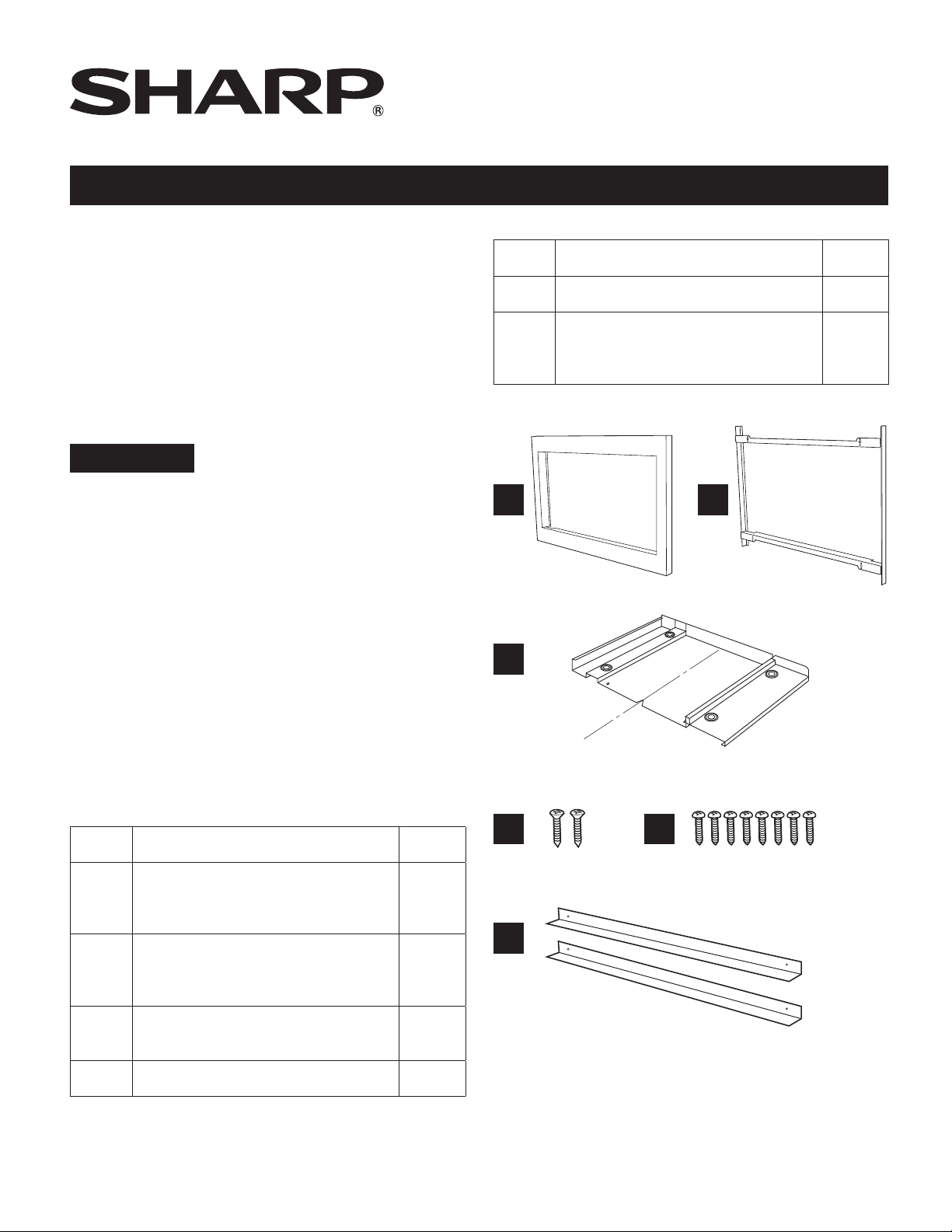
ITEM PART NAME QTY
ITEM PART NAME QTY
E SCREW E: XOPS740P16000 8
AIR DEFLECTOR:
F
RK56S27F: PREF-B038MRP0
RK56S30F: PREF-B039MRP0
A B
C
C
L
V-cut
indicates
center of
duct
D
E
2
FRONT FRAME
A
B
C
D SCREW D: XTSS740P20000 2
RK56S27F: FDECAB252MRK0
RK56S30F: FDECAB253MRK0
BACK FRAME
RK56S27F: FDECAB255MRK0
RK56S30F: FDECAB255MRK0
EXHAUST DUCT ASSEMBLY
PDUC-B188MRP0
1
F
1
1
1
Page 2
STANDARD INSTALLATION INSTRUCTIONS
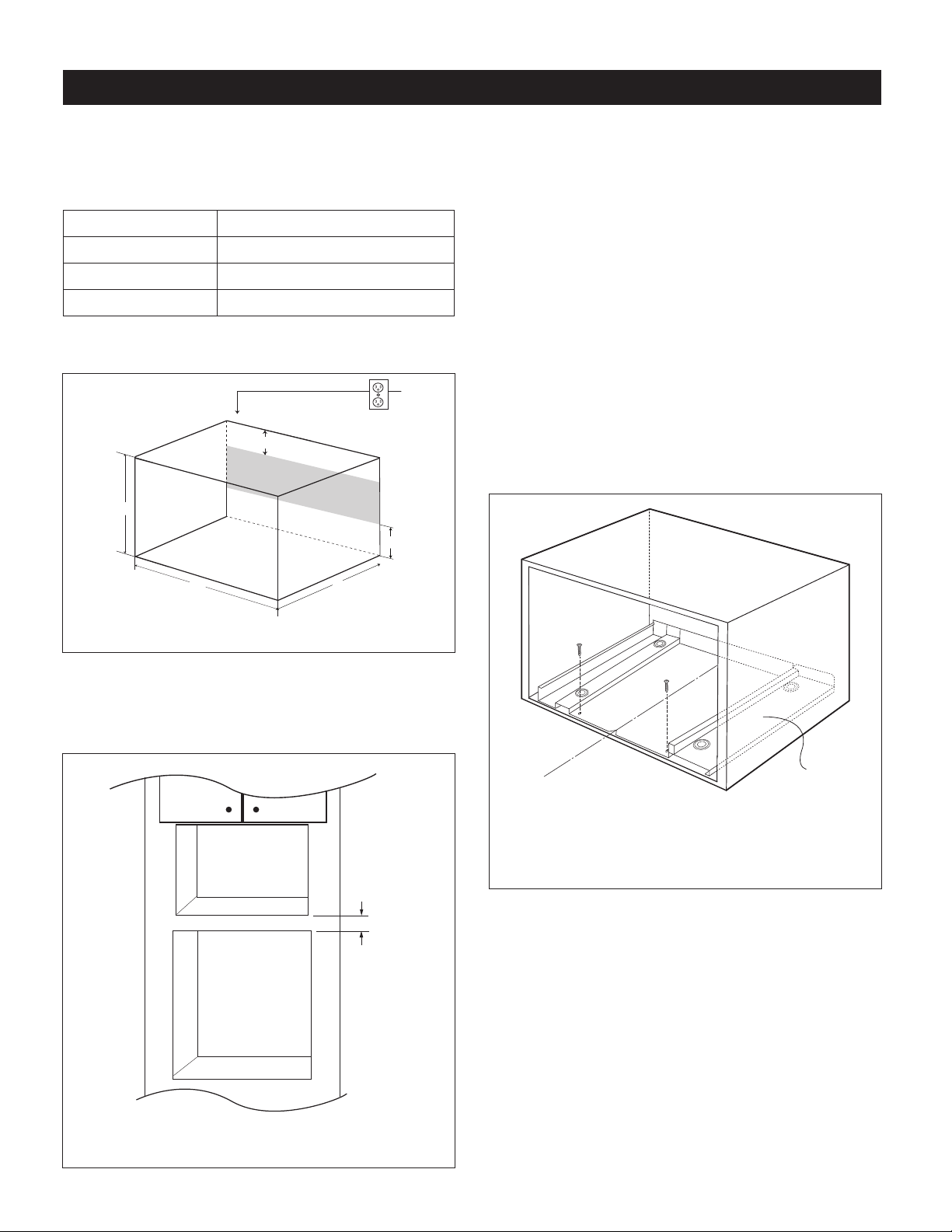
STEP 1 - CABINET OR WALL OPENING
The opening in the wall or cabinet must be within the
following dimensions:
OPENING RK56S27F, RK56S30F
Height (A) 14
Width (B) 24
Minimum Depth (C) 20" (508 mm)
Outlet should NOT be in the shaded area as indicated in
Figure 1.
A
B
1
/2" - 15 3/4" (368.3 - 400 mm)
3
/4" (628.7 mm)
4"
4"
C
• If the dimension of DEPTH (C) is more than 21" (533.4
mm), the outlet location may be any area on the rear wall.
• The oor of the opening should be constructed of
plywood strong enough to support the weight of the
oven and oor load (about 100 pounds/45 kg). The oor
should be level and 90˚ with the face of the cabinet for
proper installation and operation of the oven. Be sure to
check the local building code as it may require that the
opening be enclosed with sides, ceiling and rear partition.
The proper functioning of the oven does not require the
enclosure.
STEP 2 - EXHAUST DUCT ASSEMBLY INSTALLATION
1. Place the EXHAUST DUCT ASSEMBLY in the center of
the opening. Align the front edge of the duct with the front
of the cabinet.
2. Secure the EXHAUST DUCT ASSEMBLY with 2 SCREWS
D. See Figure 3.
FIGURE 1
NOTES
• Please allow minimum 3" wood gap between the
microwave oven cutout and the appliance cutout below
the microwave oven. See Figure 2.
Microwave cutout
3" Min.
Wall oven cutout
Screw D
Screw D
C
L
Exhaust duct
assembly, align
to front edge of
cabinet
FIGURE 3
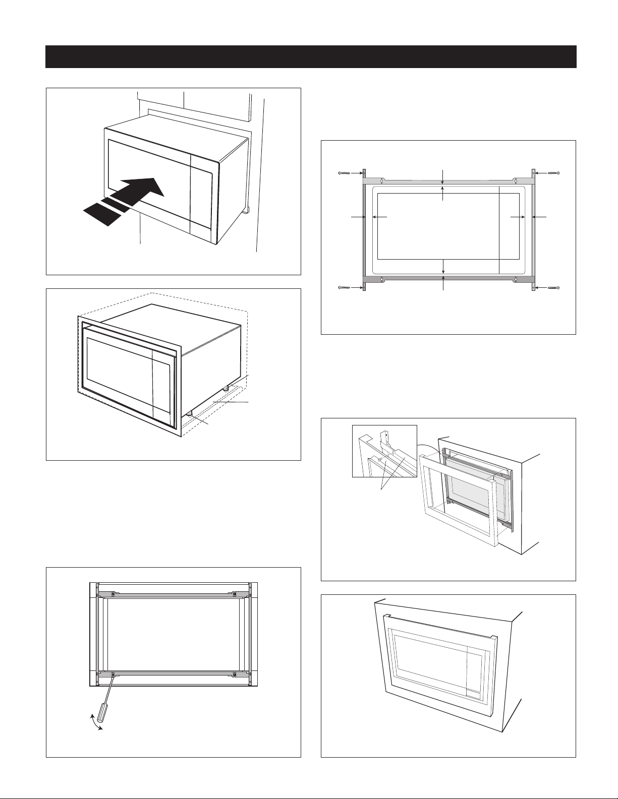
STEP 3 - FRAME INSTALLATION
1. Place the oven adjacent to the wall or cabinet opening.
Plug the POWER CORD into the electrical outlet.
2. Carefully guide the assembled oven into the prepared
opening. Slide the oven onto the EXHAUST DUCT
ASSEMBLY. See Figure 4. Avoid pinching the cord
between the oven and the wall. Adjust the position of
the oven so that the feet of the oven are tted into the
recesses of the EXHAUST DUCT ASSEMBLY and the
door opens properly. See Figure 5.
FIGURE 2
2
Page 3
STANDARD INSTALLATION INSTRUCTIONS
4. BACK FRAME INSTALLATION: Position BACK FRAME
with equal space top to bottom, side to side. Mark for 4
holes, center punch and pre-drill the cabinet with 1/16"
drill bit. Secure frame with 4 SCREWS E. See Figure 7.
FIGURE 4
FIGURE 5
Duct recess
Foot
Exhaust
duct
assembly
Screw E
Screw E
Mounting holes
Equal gap
side to side
Mounting holes
Equal gap top, bottom
Mounting holes
Screw E
Screw E
Mounting holes
FIGURE 7
5. FRONT FRAME INSTALLATION: Place the FRONT
FRAME onto the BACK FRAME and align ball studs
and receivers. Secure the FRONT FRAME to the BACK
FRAME by rmly pushing the FRONT FRAME onto the
BACK FRAME engaging the 4 snap attachments. See
Figures 8-9.
3. DISASSEMBLY: The FRONT FRAME and BACK FRAME
come pre-assembled with ball studs engaged in the
receivers. Separate the FRONT FRAME from the BACK
FRAME. Place the assembly facedown onto a protected
surface. At the location of the ball stud, insert a athead
screwdriver between the FRONT FRAME and the BACK
FRAME and gently pry up to disengage the ball stud from
the receiver. Repeat for each corner. See Figure 6.
FIGURE 6
Snap
attachment
FIGURE 8
FIGURE 9
3
Page 4

(76 MM)
FLUSH INSTALLATION INSTRUCTIONS
STEP 1 - CABINET OR WALL OPENING
The opening in the wall or cabinet must be within the
following dimensions:
OPENING RK56S27F RK56S30F
3
A 24
Width (B) 27
Height (C) 22
D 1
E 3
F 1
G 4" (101.6 mm) 4" (101.6 mm)
Minimum
Depth (I)
Outlet should NOT be in the shaded area H as indicated in
Figure 1.
/4" (628.7 mm) 24 3/4" (628.7 mm)
1
/8" (689 mm) 30 1/8" (765.2 mm)
7
/16" (569.9 mm) 22 7/16" (569.9 mm)
3
/16" (30.2 mm) 2 11/16" (67.5 mm)
1
/4" (82 mm) 3 1/4" (82 mm)
1
/2" (38.8 mm) 1 1/2" (38.8 mm)
20" (508 mm) 20" (508 mm)
Top View
Mounting
cleat
Shelf
F
A
B
Cabinet
face
NOTES
• Please allow minimum 3" (76 mm) wood gap between the
microwave oven cutout and the appliance cutout below
the microwave oven. See Figure 2.
Microwave cutout
3"
Wall oven cutout
Min.
Figure 2
• The oor of the opening should be constructed of
plywood strong enough to support the weight of the
oven and oor load (about 100 pounds/45 kg). The oor
should be level and 90˚ with the face of the cabinet for
proper installation and operation of the oven. Be sure to
check the local building code as it may require that the
opening be enclosed with sides, ceiling and rear partition.
The proper functioning of the oven does not require the
enclosure.
Front View
G
D D
Shelf
Bottom of flush cutout
E
C
B
H
G
I
Figure 1
NOTES
Dimension C above will result in 1
1
⁄4” (31.8 mm) spaces
above and below the trim to allow for necessary intake and
exhaust air ow to ensure appliance does not overheat. Do
not reduce this spacing as doing so will void the warranty
for any issues resulting from a lack of airow.
4
Page 5

FLUSH INSTALLATION INSTRUCTIONS
STEP 2 - EXHAUST DUCT ASSEMBLY INSTALLATION
1. Place the Exhaust Duct Assembly in the center of the
opening. Align the front edge of the duct with the front
of the cabinet. Align the front edge of the right side of the
duct with the front of the shelf. See Figure 3.
2. Secure the Exhaust Duct Assembly with 2 SCREWS D.
See Figure 3.
Screw D
Screw D
Figure 3
Foot
Exhaust
duct
assembly
Duct recess
Figure 5
3. DISASSEMBLY: The FRONT FRAME and BACK FRAME
come pre-assembled with ball studs engaged in the
receivers. Separate the FRONT FRAME from the BACK
FRAME. Place the assembly facedown onto a protected
surface. At the location of the ball stud, insert a athead
screwdriver between the FRONT FRAME and the BACK
FRAME and gently pry up to disengage the ball stud from
the receiver. Repeat for each corner. See Figure 6.
STEP 3 - FRAME INSTALLATION
1. Place the oven adjacent to the wall or cabinet opening.
Plug the power cord into the electrical outlet.
2. Carefully guide the assembled oven into the prepared
opening. Slide the oven onto the Exhaust Duct Assembly.
See Figure 4. Avoid pinching the cord between the oven
and the wall. Adjust the position of the oven so that the
feet of the oven are tted into the recesses of the Exhaust
Duct Assembly and the door opens properly. See Figure 5.
Screw D
Screw D
Figure 6
Figure 4
5
Page 6

FLUSH INSTALLATION INSTRUCTIONS
4. BACK FRAME INSTALLATION: Position BACK FRAME
equal space top to bottom, side to side. Mark for 4 holes
on the installed wood cleats, center punch and pre-drill
1
with
⁄16” drill bit. Secure frame with 4 SCREWS E. See
Figure 7.
Screw E
Screw E
Mounting holes
Equal gap
side to side
Mounting holes
Equal gap top, bottom
Mounting holes
Screw E
Screw E
Mounting holes
Figure 7
5. Install Air Deectors top and bottom. Center (left and right)
the Air Deectors above and below the installed BACK
FRAME. Secure AIR DEFLECTORS with 4 SCREWS E.
See Figure 8. Mark holes and pre-drill the wood cleats
1
⁄16” drill bit.
with
6. FRONT FRAME INSTALLATION: Place the FRONT
FRAME onto the BACK FRAME and align ball studs
and receivers. Secure the FRONT FRAME to the BACK
FRAME by rmly pushing the FRONT FRAME onto the
BACK FRAME engaging the 4 snap attachments. See
Figures 9-10.
Snap
attachment
Figure 8
Figure 9
Figure 10
6
Page 7

Page 8

SHARP ELECTRONICS CORPORATION
100 Paragon Drive, Montvale, New Jersey 07645
For any other assistance or information about this kit,
please call Sharp’s Customer Assistance Center at
1-800-BE-SHARP (1-800-237-4277)
TINSEB578MRR1
12-4-19
 Loading...