

Page 1
INSTALLATION INSTRUCTIONS
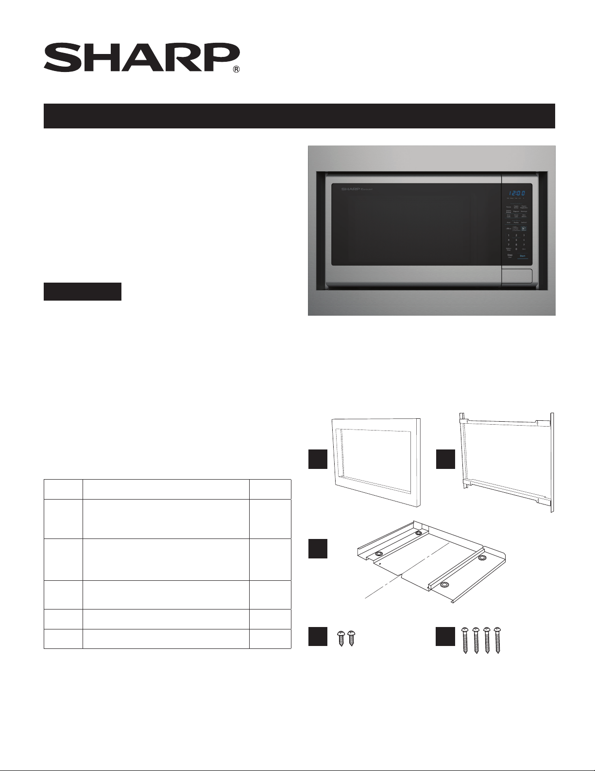
For Sharp Carousel® Built-in Kit
Models RK49S27 or RK49S30
S = STAINLESS
THIS KIT IS UL APPROVED TO ALLOW CERTAIN MICROWAVE
OVENS TO BE INSTALLED ABOVE ANY ELECTRIC WALL OVEN.
PLEASE SEE THE OPERATION MANUAL REGARDING APPROVED
BUILT-IN APPLICATIONS.
IMPORTANT:
This Built-in Kit is designed for and approved only for those
Sharp Microwave Ovens specifying Built-In Kit RK49S27 or
RK49S30. Refer to instruction manual for approved models.
PLEASE READ THESE INSTRUCTIONS
BEFORE BEGINNING INSTALLATION!
• Be sure to DISCONNECT THE PLUG of the microwave
oven from the electrical outlet before installing the Built-in
Kit. Remove the Carousel turntable from the oven cavity.
• Because the kit includes metal parts, due caution should
be used in handling and installation to avoid the possibility of injury.
THOROUGHLY
A B
ITEM PART NAME QTY
A FRONT FRAME
RK49S27: FDECAB233MRK0
RK49S30: FDECAB235MRK0
B BACK FRAME
RK49S27: FDECAB234MRK0
RK49S30: FDECAB236MRK0
C EXHAUST DUCT ASSEMBLY
PDUC-B194MRP0
D SCREW D: XTSS740P20000 2
E SCREW E: XOPS740P16000 4
1
1
1
C
C
L
V-cut
indicates
center of
duct
D
1
E
Page 2
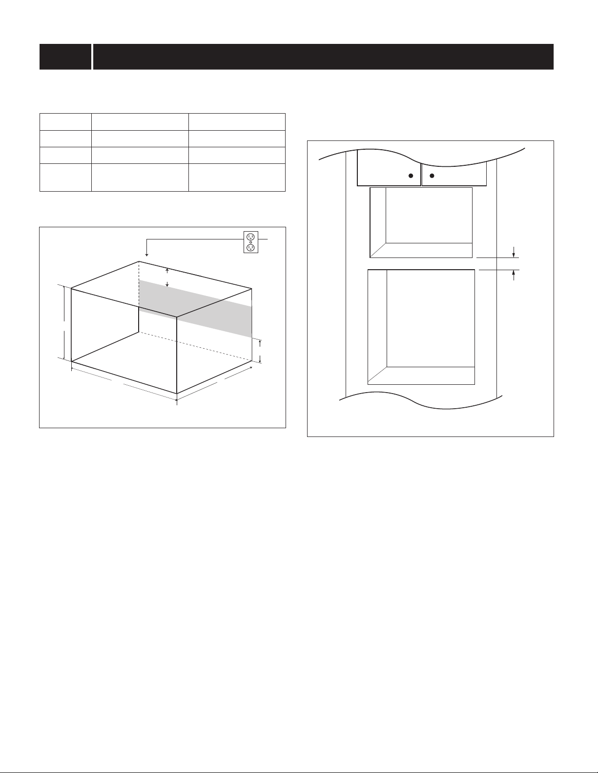
STEP 1 CABINET OR WALL OPENING
The opening in the wall or cabinet must be within the
following dimensions:
Cut Out RK49S27 RK49S30
Height (A) 14
Width (B) 24
Minimum
Depth (C)
1
/2" to 15 3/4" 14 1/2" to 15 3/4"
11
/16" to 25 5/16" 24 13/16" to 26 3/4"
20" 20"
Outlet should NOT be in the shaded area as indicated on
Sketch 1.
4"
A
4"
NOTES
• Please allow minimum 3" wood gap between the
microwave oven cutout and the appliance cutout below
the microwave oven. See Sketch 2
Microwave cutout
3" Min.
Wall oven cutout
B
C
SKETCH 1
SKETCH 2
• If the dimension of DEPTH (C) is more than 21", the outlet
location may be any area on the rear wall.
• The oor of the opening should be constructed of plywood
strong enough to support the weight of the oven and oor
load (about 100 pounds). The oor should be level and
90˚ with the face of the cabinet for proper installation and
operation of the oven. Be sure to check the local building
code as it may require that the opening be enclosed with
sides, ceiling and rear partition. The proper functioning of
the oven does not require the enclosure.
2
Page 3

STEP 2 EXHAUST DUCT ASSEMBLY INSTALLATION
1. Place the EXHAUST DUCT ASSEMBLY in the center of
the opening. Align the front edge of the duct with the front
of the cabinet.
2. Secure the EXHAUST DUCT ASSEMBLY with two
SCREWS D. See Sketch 3.
Screw D
C
L
Screw D
Exhaust duct
assembly, align
to front edge of
cabinet
SKETCH 3
STEP 3 FRAME INSTALLATION
1. Place the oven adjacent to the wall or cabinet opening.
Plug the POWER CORD into the electrical outlet.
2. Carefully guide the assembled oven into the prepared
opening. Slide the oven on the EXHAUST DUCT
ASSEMBLY. See Sketch 4. Avoid pinching the cord
between the oven and the wall. Adjust the position of
the oven so that the feet of the oven are tted into the
recesses of the EXHAUST DUCT ASSEMBLY and door
will open properly. See Sketch 5.
Foot
Exhaust
duct
assembly
Duct recess
SKETCH 5
SKETCH 4
3
Page 4

STEP 3 FRAME INSTALLATION
Mounting holes
3. BACK FRAME INSTALLATION: Position back frame equal
space top to bottom, side to side. Mark for 4 holes, center
punch and pre-drill with 1/16" drill bit. Secure frame with
4 SCREWS (E). See Sketch 6.
Screw E
Screw E
Mounting holes
Equal gap
side to side
Equal gap top, bottom
Mounting holes
Screw E
Screw E
Mounting holes
SKETCH 6
4. FRONT FRAME INSTALLATION: Place the FRONT
FRAME onto the BACK FRAME and align ball studs
and receivers. Secure the FRONT FRAME to the BACK
FRAME by rmly pushing the front frame onto the back
frame engaging the four (4) snap attachments. See
Figure 7.
Snap
Attachment
SKETCH 7
SHARP ELECTRONICS CORPORATION
100 Paragon Drive, Suite #100, Montvale, New Jersey 07645
For any other assistance or information about this kit,
please call Sharp’s Customer Assistance Center at
1-800-BE-SHARP (1-800-237-4277)
TINSEB556MRR0
4
 Loading...