

Page 1

SERVICE MANUAL
S71101R84STM/
GRILL AND CONVECTION
MICROWAVE OVEN
MODEL
R-84STM
In interests of user-safety the oven should be restored to its original
condition and only parts identical to those specified should be used.
TABLE OF CONTENTS
Page
SERVICING ............................................................................................................................................. 2
CAUTION, MICROWAVE RADIATION.................................................................................................... 3
WARNING.................................................................................................................................................3
APPEARANCE ......................................................................................................................................... 4
PRODUCT SPECIFICATIONS .................................................................................................................5
OPERATION SEQUENCE........................................................................................................................6
TEST PROCEDURES ............................................................................................................................. 7
TOUCH CONTROL PANEL ASSEMBLY .............................................................................................. 10
COMPONENT REPLACEMENT AND ADJUSTMENT PROCEDURE .................................................. 16
MICROWAVE MEASUREMENT ........................................................................................................... 18
SCHEMATIC DIAGRAM ........................................................................................................................ 19
PICTORIAL DIAGRAM .......................................................................................................................... 20
POWER UNIT CIRCUIT DIAGRAM........................................................................................................ 21
CPU UNIT CIRCUIT DIAGRAM.............................................................................................................. 22
PRINTED WIRING BOARD DIAGRAM ..................................................................................................23
PARTS LIST .......................................................................................................................................... 24
EXPLODED DIAGRAM OF OVEN PARTS ............................................................................................ 27
CONTROL PANEL/DOOR PARTS ......................................................................................................... 28
MISCELLANEOUS/PACKING & ACCESSORIES .................................................................................. 29
SHARP CORPORATION
R-84STM - 1
Page 2

SERVICING
WARNING TO SERVICE PERSONNEL
Microwave ovens contain circuitry capable of producing very high voltage and current. Contact with following parts
will result in electrocution:High voltage capacitor, High voltage transformer, Magnetron, High voltage rectifier, High voltage wires.
REMEMBER TO CHECK
1) Disconnect the supply.
2) Door opened, and wedged open.
3) Discharge high voltage capacitor.
WARNING AGAINST THE CHARGE OF THE HIGH-VOLTAGE CAPACITOR
The high-voltage capacitor remains charged about 60 seconds after the oven has been switched off. Wait for 60
seconds and then short-circuit the connection of the high-voltage capacitor (that is, of the connecting lead of the highvoltage rectifier) against the chassis using a screwdriver with an insulated handle.
Sharp recommend that wherever possible, fault-finding is carried out with the supply disconnected. In some cases, it
may be necessary to connect the supply with the cover removed to carry out fault investigation in the control circuitry.
In such cases, the high voltage circuit should be disabled as described below to reduce the hazards:-
• Carry out 3D checks (see above).
• Disconnect the supply leads from the high voltage transformer, making a note of the polarity. Insulate the
connectors, ensuring they are positioned away from the transformer and fastened there.
• Connect any relevant test equipment e.g. voltmeter.
• Reconnect the oven to the supply, then close the door.
• Note the results of the test, taking care to keep clear of the operational oven.
• Carry out 3D checks (see above).
• Reconnect the leads to the transformer. Take care to observe correct polarity.
• Carry out 4R checks (see below).
Microwave ovens should not be used without a load. To test for the presence of microwave energy within a cavity,
place a cup of cold water on the oven turntable, close the door and set the microwave timer for one (1) minute, set the
power level to HIGH (100%) and push the start key. When the one (1) minute has elapsed (timer at zero) carefully check
that the water is now hot.
3D
AFTER REPAIR REMEMBER TO CHECK 4R
1) Reconnect all leads removed from components during testing.
2) Replace the outer case (cabinet).
3) Reconnect the supply.
4) Run the oven. Check all functions.
When all service work is completed, and the oven is fully assembled, the microwave power output should be checked
and microwave leakage test carried out.
IMPORTANT: If the oven becomes inoperative because of a blown fuse F8A Fuse, check the monitored latch switch
and monitor switch before replacing the fuse F8A.
WARNING: WIRING / RE-WIRING
Before carrying out any work; carry out 3D checks.
1) Disconnect the supply.
2) Open the door and wedge open.
3) Discharge the high voltage capacitor.
RE-WIRING
1) Wires must not touch:
a) High voltage parts.
b) Parts that become hot.
c) Sharp edges.
d) Movable parts.
2) Positive lock connectors are fitted correctly
3) Wires are connected correctly as per pictorial diagram.
4) No wire leads are trapped by the outer wrap.
R-84STM - 2
Page 3

CAUTION / WARNING
CAUTION
MICROWAVE RADIATION
Do not become exposed to radiation from the
magnetron or other parts conducting microwave
energy. All input and output microwave connections,
waveguides, flanges and gaskets must be secured.
Never operate the device without a microwave
energy absorbing load attached. Never look into an
open waveguide or antenna while the device is
energized.
Servicing and repair work must be carried out only by
trained service engineers.
The parts marked '*' on the parts list and schematic
diagram have voltages in excess of 250V.
Removal of the outer wrap gives access to potential
above 250V.
All the parts marked "∆" on the parts list may cause undue
microwave exposure, by themselves, or when they are
damaged, loosened or removed.
WARNING
WARNING
THIS APPLIANCE MUST BE EARTHED
IMPORTANT
THE WIRES IN THIS MAINS LEAD ARE COLOURED IN ACCORDANCE WITH THE FOLLOWING CODE:
GREEN-AND-YELLOW : EARTH
BLUE : NEUTRAL
BROWN : LIVE
If the mains lead is replaced, only part number QACCBA004URE3 should be used
R-84STM - 3
Page 4
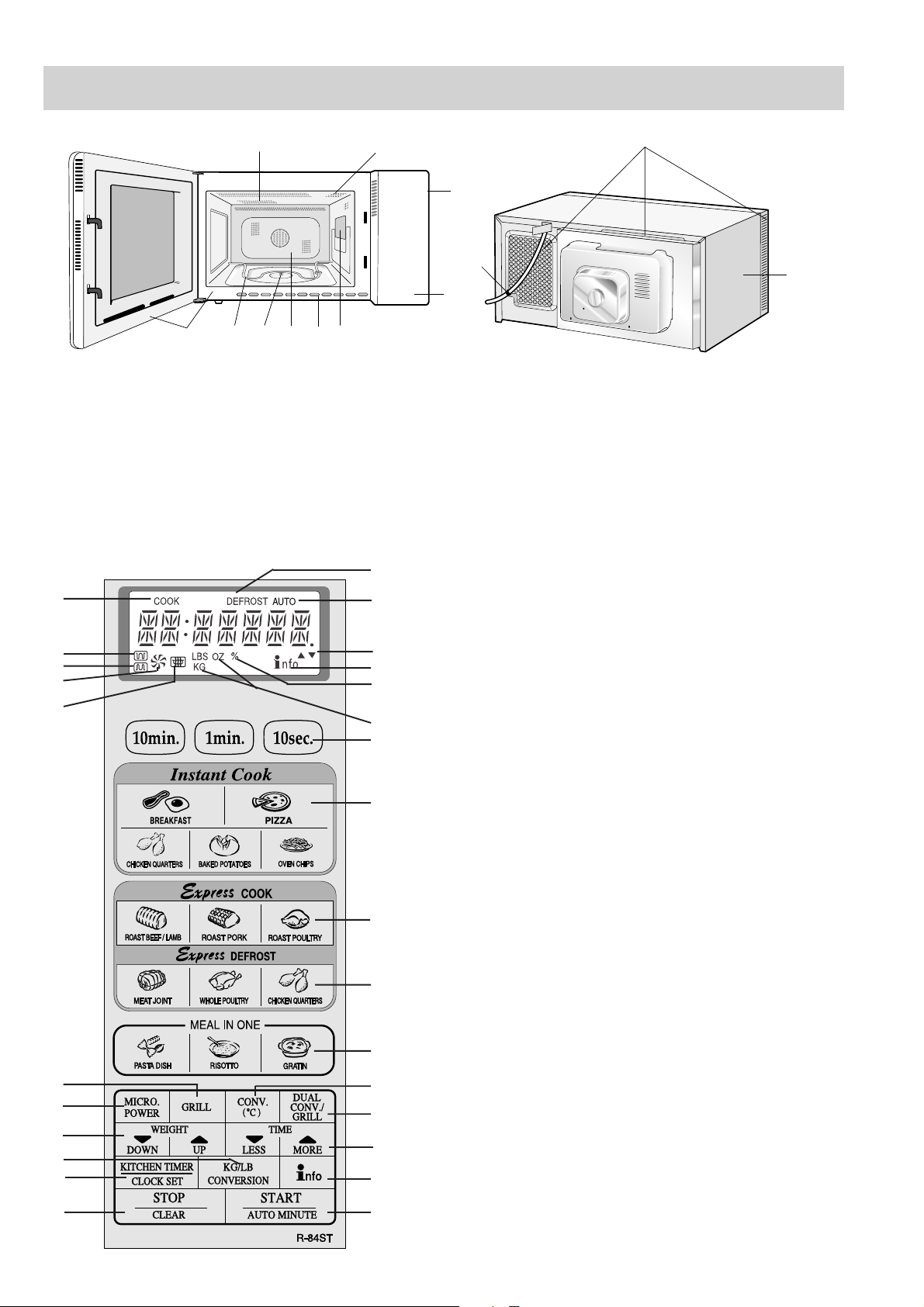
APPEARANCE VIEW
OVEN
5
4
3
2
1
27
26
25
24
23
1
8
9
7
10
6
1. Grill heating element (top grill)
2. Oven lamp
3. Control panel
4. Door opening button
5. Waveguide cover
6. Oven cavity
CONTROL PANEL
10
2
3
12
11
4
5
7. Turntable motor shaft
8. Grill heating element (bottom grill)
9. Door seals
10. Air-vent openings
11. Outer cabinet
12. Power cord
6
7
DIGITALAL DISPLAY
1. MICROWAVE indicator
2. CONVECTION indicator
8
9
10
3. BOTTOM GRILL indicator
4. TOP GRILL indicator
5. COOK indicator
6. DEFROST indicator
11
12
7. AUTO indicator
8. LESS/MORE indicators
9. INFO indicator
10. MICROWAVE POWER LEVEL percentage
11. WEIGHT indicators
13
CONTROL PANEL
12. TIME keys
13. INSTANT COOK keys
14. EXPRESS COOK keys
15. EXPRESS DEFROST keys
14
16. MEAL IN ONE keys
17. CONV. (
0
C) key
18. DUAL CONV./GRILL key
19. LESS/MORE keys
15
20. INFO key
21. START/AUTO MINUTE key
22. STOP/CLEAR key
23. KITCHEN TIMER/CLOCK SET key
16
24. WEIGHT CONVERSION key
25. WEIGHT keys
17
18
19
20
26. MICRO. POWER key
27. GRILL key
21 22
R-84STM - 4
Page 5

SPECIFICATION
ITEM DESCRIPTION
Power Requirements 230 - 240 Volts / 50 Hertz / Single phase, 3 wire earthed
Power Consumption Microwave cooking 1.45kW Approx. 6.5A
Dual cooking
(Microwave and Top Grill) 2.4kW Approx. 10.4A
(Microwave and Bottom grill) 1.95kW Approx. 8.5A
(Microwave and Convection) 2.4kW Approx. 10.4A
(Top and Bottom Grill) 1.55kW Approx. 6.3A
Convection cooking 2.08kW Approx. 9.1A
Grill Cooking
(Top Grill) 1.05kW Approx. 4.2A
(Bottom Grill) 0.55kW Approx. 2.3A
Power Output 900 watts nominal of RF microwave energy (measured by method of IEC
60705) Operating fequency 2450 MHz
Grill heating element Power Output Top Grill 1.kW Bottom Grill 0.5kW
Case Dimensions Width 520 mm Height 309 mm (including foot) Depth 488 mm
Cooking Cavity Dimensions Width 349 mm Height 207 mm Depth 357 mm
Turntable diameter 325mm
Control Complement Touch Control System
Microwave Cooking Control
Repetition Rate;
HIGH ............. Full power throughout the cooking time
MEDIUM HIGH ............. approx. 70% of FULL Power
MEDIUM ....................... approx. 50% of FULL Power
MEDIUM LOW .............. approx. 30% of FULL Power
LOW ............................. approx. 10% of FULL Power
TIME keys STOP/CLEAR key
INSTANT COOK keys KITCHEN TIMER/CLOCK SET key
EXPRESS COOK keys WEIGHT CONVERSION key
EXPRESS DEFROST keys WEIGHT keys
MEAL IN
CONV. (
DUAL CONV./GRILL key
LESS(
INFO keys
START/AUTO MINUTE key
ONE keys MICRO. POWER key
0
C) key GRILL key
)/MORE( ) keys
Net Weight Approx. 20 kg
As part of our policy of continuous improvement, we reserve the right to
alter design and specifications without notice
Note:
Temperature measurements taken whilst the oven is in convection mode will differ from the displayed level.
This is due to the grill elements turning on and off in order to regulate the oven temperature.
This will not affect the cooking results as long as the operation manual and cook book are followed correctly.
R-84STM - 5
Page 6

OPERATION SEQUENCE
OFF CONDITION
Closing the oven door activates all door interlock switches
(monitored latch switch and stop switch).
IMPORTANT:
When the oven door is closed, the contacts
monitor switch
SW2 must be open and the contacts (COM-
COM-NC of the
NO) must be closed. When the microwave oven is plugged
into a wall outlet (230-240V / 50Hz), 230-240 volts A.C. is
supplied to the point
A1 + A3 in the control unit.
1. The display starts demo mode.
2. To set any programmes or set the clock, you must first
touch the STOP key.
3. Information appears on display.
NOTE: When the oven door is opened, the oven lamp
comes on at this time.
MICROWAVE COOKING CONDITION
HIGH COOKING
Enter a desired cooking time with the Time keys and start the
oven with touching START key.
Function sequence Figure O-1 on page 18
CONNECTED COMPONENTS RELAY
Oven lamp, Turntable motor RY1
High voltage transformer RY2
Fan motor RY6
1 When the cooking time is up, a signal tone is heard and
the relays
position. The circuits to the oven lamp, high voltage
transformer, fan motor and turntable motor are cut off.
2. When the oven door is opened during a cooking cycle,
the switches come to the following condition.
Switch Contact Condition
Monitored latch Switch COM-NO Closed Opened
Monitor Switch COM-NO Closed Opened
Monitor Switch COM-NC Opened Closed
Stop switch
RY1 + RY2 + RY6 go back to their home
During Oven Door
Cooking Open(No cooking)
COM-NO Closed Opened
NO) first. After that the contacts (COM-NC) of the
monitor switch
(
COM-NO) of monitor switch SW2 are made open.
3-2. When the oven door is closed. The contacts (
of the monitor switch
SW2 can be closed and the contacts
COM-NC)
SW2 must be opened and the
contacts (COM-NO) of monitor switch SW2 must be
closed. After that the contacts of the monitored latch
switch
SW1 and the stop switch SW3 are made closed.
3-3. When the oven door is opened and the contacts of the
monitored latch switch
F8A will blow. Because the relay
SW1 remain closed, the fuse F2
RY1 and monitor
switch SW2 are closed and a short circuit is caused.
MEDIUM HIGH, MEDIUM, MEDIUM LOW, LOW
COOKING
When the microwave oven is preset for variable cooking
power, the 230-240 volts A.C. power is supplied to the high
voltage transformer intermittently within a 32-second time
base through the relay contact which is coupled with the
current-limiting relay
power are given.
Note: The On/Off time ratio does not exactly correspond to
the percentage of microwave power, because
3 seconds are needed for heating up the
magnetron filament.
RY2. The following levels of microwave
32 sec. ON
HIGH
MEDIUM
HIGH
MEDIUM
MEDIUM
LOW
LOW
24 sec. ON
18 sec. ON
12 sec. ON
6 sec. ON
8 sec. OFF
14 sec. OFF
20 sec. OFF
28 sec. OFF
approx.
Approx 100%
Approx. 100%
Approx. 70%
Approx. 50%
Approx. 30%
Approx. 10%
The circuit to the high voltage transformer, is cut off when the
contact of relay
RY2 contacts COM-NO of the monitored
latch switch SW1, and monitor switch SW2 are made open.
The circuit to the fan motor is cut off when the relay
RY6 is
made open. The circuit to the turntable motor is cut off when
the contacts
The relay
COM-NO of the monitor switch are made open.
RY2 and RY6 are made open when the door is
opened. The oven lamp remains on even if the oven door is
opened after the cooking cycle has been interrupted, because
the relay
RY1 stays closed. Shown in the display is remaining
time.
3. MONITOR SWITCH CIRCUIT
The monitor switch
SW2 is mechanically controlled by
the oven door, and monitors the operation of the monitored
latch switch
SW1.
3-1. When the oven door is opened during or after the cycle
of a cooking program, the monitored latch switch
and stop switch
SW3 must open their contacts (COM-
SW1
R-84STM - 6
Page 7

TEST PROCEDURES
SENSING FIRE OPERATION
The oven will stop its operation when there is a fire in the
oven cavity in microwave cooking condition.
LSI measures the voltage across the temperature measurement circuit intermittently within a 32-second time base once
the oven is started in the microwave cooking mode. The oven
will stop its operation when the difference of the voltages is
more than 0.69 volts in microwave cooking condition.
1. Within a 32-second base, first the thermistor is energized
for 3 seconds. After 2 seconds since the thermistor is
energized, the voltage across the temperature
measurement circuit is measured. And after 21 seconds
since the thermistor is cut off, the convection motor
operates for 10 seconds.
2. The oven carries out the procedure above again. If the
second voltage is 0.69V higher than the first voltage, LSI
judges it is a fire in the oven cavity and stops the oven.
3. When sensor cooking, the sensing fire operation is not
carried out until the oven senses the steam from food.
Because food cannot be cooked well by rotating the
convection fan at that time. After sensing the steam, the
sensing fire operation is started.
4. When LSI judges it is fire in the oven cavity, LSI will switch
off the relays to the power transformer, fan motor and
convection motor and LSI stops counting down. And then
the damper is closed so that the fresh air does not come
into the oven cavity.
0 2 20 30 32 64 (sec.)
CONVECTION
MOTOR
THERMISTOR
Sensing
Voltage
ON
OFF
3 sec.
ON
OFF
ON
OFF
Sensing the voltage across temperature measurement circuit.
TEST PROCEDURES
MICROWAVE OUTPUT POWER (IEC-60705)
The power output of this oven is rated using the method specified by IEC-60705. Full details of how to carry out this
procedure can be found in the Sharp Technical Training notes which is available from Sharp Parts Centre
(part number SERV-LITMW01).
The IEC-60705 procedure must be carried out using laboratory-type procedures and equipment. These requirements
make the procedure unsuitable for routine performance checks.
Note: The following test method gives an indication of the output power only, it cannot be used to establish the actual/
rated output power. If the true output power is required, then the IEC-60705 test method must be used.
Alternative simplified method:
1. Place 2 litres of cold water (between 12°C and 20°C) in a suitable container.
2. Stir the water and measure the temperature in °C. Note temperature as T1.
3. Place the container in the microwave and heat the water for 2 minutes on full power.
4. When the 2 minutes is completed, remove the container and stir the water. Note the water temperature as T2.
5. Calculate the output power using the following formula:
R.F. Power Output = (T2 - T1) x 90.
MICROWAVE LEAKAGE TEST
This oven should be tested for microwave leakage on completion of any repair or adjustment, following the procedure
described in the Sharp Technical Training notes (part number SERV-LITMW01). The maximum leakage permitted in
BS EN 60335-2-25 is 50W/m
therefore, any leakage which is detected should be investigated.
2
(equivalent to 5mW/cm2), however it is not normal to detect any significant leakage,
It is essential that only leakage detectors with current calibration traceable to the National Physical Laboratories are
used.
Suitable leakage detectors : CELTEC A100
APOLLO X1
R-84STM - 7
Page 8

TEST PROCEDURES
PROCEDURE
LETTER COMPONENT TEST
A TOUCH CONTROL PANEL ASSEMBLY TEST
The touch control panel consists of circuits including semiconductors such as LSI, ICs, etc. Therefore,
unlike conventional microwave ovens, proper maintenance can not be performed with only a voltmeter and
ohmmeter.
In this service manual, the touch control panel assembly is divided into two units, Control Unit and Key Unit,
and also the Control unit is divided into two units, CPU unit and Power unit, and troubleshooting by
replacement is described according to the symptoms indicated.
1. Key Unit Note : Check key unit ribbon connection before replacement.
The following symptoms indicate a defective key unit. Replace the key unit.
a) When touching the pads, a certain pad produces no signal at all.
b) When touching a number pad, two figures or more are displayed.
c) When touching the pads, sometimes a pad produces no signal.
2. Control Panel
The following symptoms indicate a defective control unit. Before replacing the control unit perform the
key unit test (Procedure P) to determine if control unit is faulty.
2-1 In connection with pads
a) When touching the pads, a certain group of pads do not produce a signal.
b) When touching the pads, no pads produce a signal.
2-2 In connection with indicators
a) At a certain digit, all or some segments do not light up.
b) At a certain digit, brightness is low.
c) Only one indicator does not light up.
d) The corresponding segments of all digits do not light up; or they continue to light up.
e) Wrong figure appears.
f) A certain group of indicators do not light up.
g) The figure of all digits flicker.
2-3 Other possible troubles caused by defective control unit.
a) Buzzer does not sound or continues to sound.
b) Clock does not operate properly.
c) Cooking is not possible.
d) Proper temperature measurement is not obtained.
B KEY UNIT TEST
If the display fails to clear when the STOP/CLEAR pad is depressed, first verify the flat ribbon
cable is making good contact, verify that the stop switch operates properly; that is the contacts
are closed when the door is closed and open when the door is open. If the stop switch is good,
disconnect the flat ribbon cable that connects the key unit to the control unit and make sure the
stop switch is closed (either close the door or short the stop switch connecter). Use the Key unit
matrix indicated on the control panel schematic and place a jumper wire between the pins that
correspond to the STOP/CLEAR pad making momentary contact. If the control unit responds by
clearing with a beep the key unit is faulty and must be replaced. If the control unit does not
respond, it is faulty and must be replaced. If a specific pad does not respond, the above method
may be used (after clearing the control unit) to determine if the control unit or key pad is at fault.
ROAST POULTRY
CHICKEN QUARTERS
G12 G11 G10 G 9
CARRY OUT 4R CHECKS.
G 8 G 7 G 6 G 5 G 4 G 3 G 2 G 1
ROAST PORK
PIZZA
MORE
DUAL CONV. /
GRILL
WHOLE POULTRY
GRATIN
LESS
PASTA DISH
MEAT JOINT
BAKED POTATOES
OVEN CHIPS
STOP
CLEAR
ROAST BEEF / LAMB
CHICKEN QUARTERS (INSTANT COOK)
START
AUTO MINUTE
KG / LB
CONVERSION
RISOTTO
UP
KITCHEN TIMER
CLOCK SET
GRILL
MICRO.
POWER
CONV.
( ˚C )
BREAKFAST
DOWN
R-84STM - 8
Page 9

TEST PROCEDURES
PROCEDURE
LETTER COMPONENT TEST
C RELAY TEST
CARRY OUT 3D CHECKS.
Remove the outer case and check voltage between Pin Nos. 1 and 3 of the 4 pin connector (E) on the control
unit with an A.C. voltmeter.
The meter should indicate 230-240 volts, if not check oven circuit.
Relay Test
Check voltage at the relay coil with a D.C. voltmeter during the microwave cooking operation, grill
operation, convection operation or dual operation.
DC. voltage indicated ............. Defective relay.
DC. voltage not indicated....... Check diode which is connected to the relay coil. If diode is good, control
unit is defective.
RELAY SYMBOL OPERATIONAL VOLTAGE CONNECTED COMPONENTS
RY1 Approx. 18.0V D.C. Oven lamp / Turntable motor
RY2 Approx. 18.0V D.C. High voltage transformer
RY3 Approx. 24.0V D.C. Grill (Top) heating element
RY4 Approx. 24.0V D.C. Bottom heating element
RY5 Approx. 24.0V D.C. Touch control transformer
RY6 Approx. 24.0V D.C. Fan motor
RY7 Approx. 24.0V D.C. Convection motor
CARRY OUT 4R CHECKS.
D PROCEDURES TO BE TAKEN WHEN THE FOIL PATTERN ON THE PRINTED WIRING
BOARD(PWB) IS OPEN
To protect the electronic circuits, this model is provided with a fine foil pattern added to the input circuit on
the PWB, this foil pattern acts as a fuse. If the foil pattern is open, follow the troubleshooting guide given
below for repair.
Problem: POWER ON, indicator does not light up.
CARRY OUT
STEPS OCCURRENCE CAUSE OR CORRECTION
1 The rated AC voltage is not present between Check supply voltage and oven power cord.
2 The rated AC voltage is present at primary Low voltage transformer or secondary circuit defective.
3 Only pattern at "a" is broken. *Insert jumper wire J1 and solder.
4 Pattern at "a" and "b" are broken. *Insert the coil RCILF2003YAZZ between "c" and "d".
NOTE: *At the time of these repairs, make a
3D CHECKS.
Pin Nos. 1 and 3 of the 4-pin connector (E).
side of low voltage transformer. Check and repair.
(CARRY OUT 3D CHECKS BEFORE REPAIR.)
(CARRY OUT 3D CHECKS BEFORE REPAIR.)
visual inspection of the varistor for burning damage and examine the trans-
CN - E
former with tester for the presence of
layer short circuit (check primary coil
resistance).
d
b
7
a
(J1)
RY6
9
CN - A
If any abnormal condition is detected,
replace the defective parts.
VRS1
c
1
FM
RY4
(J2)
CARRY OUT 4R CHECKS.
R-84STM - 9
F
POWER
Page 10

TOUCH CONTROL PANEL ASSEMBLY
OUTLINE OF TOUCH CONTROL PANEL
The touch control section consists of the following units as
shown in the touch control panel circuit.
(1) Key Unit
(2) Control Unit (The Control unit consists of Power unit and
CPU unit.)
The principal functions of these units and signals communicated among them are explained below.
Key Unit
The key unit is composed of a matrix, signals generated in the
LSI are sent to the key unit from P40, P41, P72, P73 P74, P75,
P76 and P77.
When a key pad is touched, a signal is completed through the
key unit and passed back to the LSI through P44 - P47 to
perform the function that was requested.
Control Unit
Control unit consists of LSI, power source circuit, synchronizing signal circuit, ACL circuit, buzzer circuit, relay circuit,
temperature measurement circuit, indicator circuit and back
light circuit.
1) LSI
This LSI controls the temperature measurement signal,
key strobe signal, relay driving signal for oven function
and indicator signal.
2) Power Source Circuit
This circuit generates voltage necessary in the control
unit.
initial state when power is supplied.
5) Buzzer Circuit
The buzzer is responsive to signals from the LSI to emit
audible sounds (key touch sound and completion sound).
6) Stop Switch
A switch to "tell" the LSI if the door is open or closed.
7) Relay Circuit
To drive the magnetron, grill heating element, bottom
heating element, convection motor, fan motor, turntable
motor, touch control transformer and light the oven lamp.
8) Back Light Circuit
A circuit to drive the back light (Light emitting diodes LD1
- LD10).
9) Indicator Circuit
This circuit consists 7-digits, 39-segments and 3-common
electrodes using a Liquid Crystal Display.
10) Temperature Measurement Circuit : (OVEN
THERMISTOR)
The temperature in the oven cavity is sensed by the
thermistor. The variation of resistance according to
sensed temperature is detected by the temperature
measurement circuit and the result applied to LSI.
The LSI uses this information to control the relay
and display units.
Symbol Voltage Application
VC -5.2V LSI(IC1)
3) Synchronizing Signal Circuit
The power source synchronizing signal is available in
order to compose a basic standard time in the clock circuit.
It accompanies a very small error because it works on
commercial frequency.
4) ACL
A circuit to generate a signal which resets the LSI to the
R-84STM - 10
Page 11

TOUCH CONTROL / DESCRIPTION OF LSI
LSI(IXA094DR)
The I/O signal of the LSI(IXA094DR) are detailed in the following table.
Pin No. Signal I/O Description
1 C1 IN Terminal not used.
2 VL1 IN Power source voltage input terminal.
Standard voltage for LCD.
3 AN7 IN Terminal to change the on timing of the cook relay (RY2).
4-5 AN6-AN5 IN Heating constant compensation terminal.
6 AN4 OUT Terminal not used.
7 AN3 IN Temperature measurement input: OVEN THERMISTOR.
By inputting DC voltage corresponding to the temperature detected by the
thermistor, this input is converted into temperature by the A/D converter built
into the LSI.
8 AN2 IN Input signal which communicates the door open/close information to LSI.
Door closed; "H" level signal.
Door opened; "L" level signal.
9-10 AN1-AN0 OUT Terminal not used.
11 P57 OUT Timing signal output terminal for temperature measurement(OVEN
THERMISTOR).
"H" level (GND) : Thermistor OPEN timing.
"L" level (-5V) : Temperature measuring timing. (Convection cooking)
12 P56 OUT Signal to sound buzzer.
A: key touch sound.
B: Completion sound.
C: When the temperature of the oven
cavity reaches the preset
temperature in the preheating
mode, or when the preheating hold
time (30 minutes) is elapsed.
13 P55 OUT Timing signal output terminal for temperature measurement(OVEN
THERMISTOR).
"H" level (GND) : Thermistor OPEN timing.
"L" level (-5V) : Temperature measuring timing. (Convection cooking)
14-18 P54-P50 OUT Terminal not used.
19 P47 IN Signal coming from touch key.
When any one of G12 line keys on key matrix is touched, a corresponding
signal from P40, P41, P72, P73, P74, P75, P76 and P77 will be input into P47.
When no key is touched, the signal is held at "L" level.
20 P46 IN Signal similar to P47.
When any one of G11 line keys on key matrix is touched, a corresponding
signal will be input into P46.
21 P45 IN Signal similar to P47.
When any one of G10 line keys on key matrix is touched, a corresponding
signal will be input into P45.
22 P44 IN Signal similar to P47.
When any one of G9 line keys on key matrix is touched, a corresponding signal
will be input into P44.
23 INT1 OUT Terminal not used.
24 INT0 IN Signal to synchronized LSI with commercial power source
frequency(50Hz).
This is basic timing for time processing
of LSI.
A
B
1.2 sec
C
0.12 sec
2.4 sec
20 msec.
1.2 sec
H: GND
L
H : GND
L (-5V)
25 P41 OUT Key strobe signal.
Signal applied to touch-key section. A pulse signal is input to P44 - P47
terminal while one of G8 line key on matrix is touched.
R-84STM - 11
Page 12

TOUCH CONTROL / DESCRIPTION OF LSI
LSI(IXA094DR)
The I/O signal of the LSI(IXA094DR) are detailed in the following table.
Pin No. Signal I/O Description
26 P40 OUT Key strobe signal.
Signal applied to touch-key section. A pulse signal is input to P44 - P47
terminal while one of G7 line key on matrix is touched.
27 P77 OUT Key strobe signal.
Signal applied to touch-key section. A pulse signal is input to P44 - P47
terminal while one of G6 line key on matrix is touched.
28 P76 OUT Key strobe signal.
Signal applied to touch-key section. A pulse signal is input to P44 - P47
terminal while one of G5 line key on matrix is touched.
29 P75 OUT Key strobe signal.
Signal applied to touch-key section. A pulse signal is input to P44 - P47
terminal while one of G4 line key on matrix is touched.
30 P74 OUT Key strobe signal.
Signal applied to touch-key section. A pulse signal is input to P44 - P47
terminal while one of G3 line key on matrix is touched.
31 P73 OUT Key strobe signal.
Signal applied to touch-key section. A pulse signal is input to P44 - P47
terminal while one of G2 line key on matrix is touched.
32 P72 OUT Key strobe signal.
Signal applied to touch-key section. A pulse signal is input to P44 - P47
terminal while one of G1 line key on matrix is touched.
33 P71 OUT Oven lamp and turntable motor driving signal(Square Waveform : 50Hz).
To turn on and off shut-off relay
(RY1). The square waveform voltage
is delivered to the relay (RY1) driving
circuit.
20 msec.
During cooking
H
L
34 P70 IN Connected to VC.
35 RESET IN Auto clear terminal.
Signal is input to reset the LSI to the initial state when power is applied.
Temporarily set to "L" level the moment power is applied, at this time the LSI is
reset. Thereafter set at "H" level.
36 P81 OUT Magnetron high-voltage circuit driving signal.
To turn on and off the cook
relay (RY2). In 100%
operation, the signals hold "L"
level during microwave
cooking and "H" level while not
cooking. In other cooking
modes (70%, 50%, 30%,
10%) the signal turns to "H"
level and "L" level in repetition
according to the power level.
ON/OFF time ratio in Micro
cooking
(a. 32second time base)
MICRO ON OFF
COOK
100% 32 sec. 0 sec.
70% 24 sec. 8 sec.
50% 18 sec. 14 sec.
30% 12 sec. 20 sec.
10% 6 sec. 26 sec.
37 P80 OUT Grill (TOP) heating element driving signal.
To turn on and off the grill heating
element relay (RY3). "L" level
during grill cooking, convection
cooking or dual cooking, "H" level
otherwise. The heater relay turns
on and off within a 48 second time
base in accordance with the
special program in LSI.
Power output ON time OFF time
100 % 48 sec. 0 sec.
90 % 44 sec. 4 sec.
80 % 40 sec. 8 sec.
70 % 36 sec. 12 sec.
60 % 32 sec. 16 sec.
50 % 26 sec. 22 sec.
40 % 22 sec. 26 sec.
30 % 16 sec. 32 sec.
20 % 12 sec. 36 sec.
10 % 8 sec. 40 sec.
ON/OFF time ratio in Micro
cooking
(a. 48second time base)
MICRO ON OFF
COOK
100% 48 sec. 0 sec.
70% 36 sec. 12 sec.
50% 26 sec. 22 sec.
30% 16 sec. 32 sec.
10% 8 sec. 40 sec.
R-84STM - 12
Page 13

TOUCH CONTROL / DESCRIPTION OF LSI
LSI(IXA094DR)
The I/O signal of the LSI(IXA094DR) are detailed in the following table.
Pin No. Signal I/O Description
38 XIN IN Internal clock oscillation frequency input setting.
The internal clock frequency is set by inserting the ceramic filter oscillation
circuit with respect to XOUT terminal.
39 XOUT OUT Internal clock oscillation frequency control output.
Output to control oscillation input of XIN.
40 VSS IN Power source voltage: -5V.
VC voltage of power source circuit input.
41 P27 OUT Bottom heating element driving signal.
To turn on and off the relay (RY4). "L"
level during grill cooking, convection
cooking or dual cooking, "H" level
otherwise.
The heater relay turns on and off
within a 48 second time base in
accordance with the special program
in LSI.
Power output ON time OFF time
100 % 48 sec. 0 sec.
90 % 44 sec. 4 sec.
80 % 40 sec. 8 sec.
70 % 36 sec. 12 sec.
60 % 32 sec. 16 sec.
50 % 26 sec. 22 sec.
40 % 22 sec. 26 sec.
30 % 16 sec. 32 sec.
20 % 12 sec. 36 sec.
10 % 8 sec. 40 sec.
42 P26 OUT Convection motor driving signal.
To turn on and off shut-off relay(RY7). "L"
level during convection or dual cooking "H"
level otherwise. (Relay RY7 does not turn
ON
on at preheating mode.)
43 P25 OUT Fan motor driving signal.
To turn on and off the fan motor relay RY6.
ON
"L" level during cooking, or for a while after
convection, grill (top and bottom grill) or dual
cooking. "H" level otherwise.
44 P24 OUT Terminal not used.
45 P23 OUT Touch control transformer driving signal.
To turn on and off the shut off relay (RY5). If the oven has not been used for
more than 3 minutes, the relay RY5 will be turned off. The relay RY5 will be
turned on when the oven door is opened and closed.
46-48 P22-P20 OUT Terminal not used.
49-50 P17-P16 IN Terminal to change functions according to the model.
51-80 SEG39-SEG10 OUT Segment data signal.
Connected to LCD.
The relation between signals are as follows:
LSI signal (Pin No.) LCD (Pin No.) LSI signal (Pin No.) LCD (Pin No.)
SEG 0 (90) ....................SEG39 (51) SEG21 (69) ................. SEG19 (19)
SEG 1 (89) ....................SEG38 (50) SEG22 (68) ................. SEG18 (18)
SEG 2 (88) ....................SEG37 (49) SEG23 (67) ................. SEG17 (17)
SEG 3 (87) ....................SEG36 (48) SEG24 (66) ................. SEG16 (16)
SEG 4 (86) ....................SEG35 (47) SEG25 (65) ................. SEG15 (15)
SEG 5 (85) ....................SEG34 (46) SEG26 (64) ................. SEG14 (14)
SEG 6 (84) ....................SEG33 (45) SEG27 (63) ................. SEG13 (13)
SEG 7 (83) ....................SEG32 (44) SEG28 (62) ................. SEG12 (12)
SEG 8 (82) ....................SEG31 (43) SEG29 (61) ................. SEG11 (11)
SEG10 (80) ...................SEG30 (30) SEG30 (60) ................. SEG10 (10)
SEG11 (79) ...................SEG29 (29) SEG31 (59) ................... SEG 9 ( 9)
SEG12 (78) ...................SEG28 (28) SEG32 (58) ................... SEG 8 ( 8)
SEG13 (77) ...................SEG27 (27) SEG33 (57) ................... SEG 7 ( 7)
SEG14 (76) ...................SEG26 (26) SEG34 (56) ................... SEG 6 ( 6)
SEG15 (75) ...................SEG25 (25) SEG35 (55) ................... SEG 5 ( 5)
SEG16 (74) ...................SEG24 (24) SEG36 (54) ................... SEG 4 ( 4)
SEG17 (73) ...................SEG23 (23) SEG37 (53) ................... SEG 3 ( 3)
SEG18 (72) ...................SEG22 (22) SEG38 (52) ................... SEG 2 ( 2)
SEG19 (71) ...................SEG21 (21) SEG39 (51) ................... SEG 1 ( 1)
SEG20 (70) ...................SEG20 (20)
During
cooking
(Convection or dual cooking)
During cooking or for awhile after convection,
grill (top and bottom grill ) or dual.
OFF
H.
L
OFF
GND
H.
GND
L
R-84STM - 13
Page 14

TOUCH CONTROL / DESCRIPTION OF LSI
LSI(IXA094DR)
The I/O signal of the LSI(IXA094DR) are detailed in the following table.
Pin No. Signal I/O Description
81 SEG9 OUT Terminal not used.
82-90
91 VCC IN Connected to GND.
92 VREF IN Connected to GND.
93 AVSS IN Connected to VC.
94 COM3 OUT Common data signal: COM3.
95 COM2 OUT Common data signal: COM2.
96 COM1 OUT Common data signal: COM1.
97 COM0 OUT Terminal not used.
98-99 VL3-VL2 IN Power source voltage input terminal.
100 C2 IN Terminal not used.
SEG8-SEG0 OUT Segment data signal.
Connected to LCD. Signal is similar to SEG39.
Connected to LCD (Pin No. 35).
Connected to LCD (Pin No. 34).
Connected to LCD (Pin No. 33).
Standard voltage for LCD.
R-84STM - 14
Page 15

SERVICING
1. Precautions for Handling Electronic Components
This unit uses CMOS LSI in the integral part of the circuits.
When handling these parts, the following precautions
should be strictly followed. CMOS LSI have extremely
high impedance at its input and output terminals. For this
reason, it is easily influenced by the surrounding high
voltage power source, static electricity charge in clothes,
etc., and sometimes it is not fully protected by the built-in
protection circuit.
In order to protect CMOS LSI.
1) When storing and transporting, thoroughly wrap them
in aluminium foil. Also wrap PW boards containing
them in aluminium foil.
2) When soldering, ground the technician as shown in
the figure and use grounded soldering iron and work
table.
approx. 1M ohm
2. Shapes of Electronic Components
B
C
E
Transistor
2SB1238
E
C
B
Transistor
KRC243M
3. Servicing of Touch Control Panel
We describe the procedures to permit servicing of the
touch control panel of the microwave oven and the
precautions you must take when doing so.
To perform the servicing, power to the touch control panel
is available either from the power line of the oven itself or
from an external power source.
(1) Servicing the touch control panel with power
supply of the oven :
CAUTION:
THE HIGH VOLTAGE TRANSFORMER OF THE
MICROWAVE OVEN IS STILL LIVE DURING SERVICING AND PRESENTS A HAZARD .
Therefore, before checking the performance of the touch
control panel,
1) Disconnect the power supply cord, and then remove
outer case.
2) Open the door and block it open.
3) Discharge high voltage capacitor.
4) Disconnect the leads to the primary of the power
transformer.
5) Ensure that these leads remain isolated from other
components and oven chassis by using insulation
tape.
6) After that procedure, re-connect the power supply
cord.
After checking the performance of the touch control
panel,
1) Disconnect the power supply cord.
2) Open the door and block it open.
3) Re-connect the leads to the primary of the power
transformer.
4) Re-install the outer case (cabinet).
5) Re-connect the power supply cord after the outer
case is installed.
6) Run the oven and check all functions.
A. On some models, the power supply cord between the
touch control panel and the oven itself is so short that
the two can't be separated.
For those models, check and repair all the controls
(sensor-related ones included) of the touch control
panel while keeping it connected to the oven.
B. On some models, the power supply cord between the
touch control panel and the oven is long enough that
they may be separated from each other. For those
models, therefore, it is possible to check and repair the
controls of the touch control panel while keeping it apart
from the oven, in this case you must short both ends of
the door sensing switch (on PWB) of the touch control
panel with a jumper, which brings about an operational
state that is equivalent to the oven door being closed.
As for the sensor-related controls of the touch control
panel, checking them is possible if the dummy resistor(s)
with resistance equal to that of the controls are used.
(2) Servicing the touch control panel with power
supply from an external power source:
Disconnect the touch control panel completely from
the oven, and short both ends of the door sensing
switch (on PWB) of the touch control panel, which
brings about an operational state that is equivalent to
the oven door being closed. Connect an external
power source to the power input terminal of the touch
control panel, then it is possible to check and repair the
controls of the touch control panel; it is also possible to
check the sensor-related controls of the touch control
panel by using the dummy resistor(s).
4. Servicing Tools
Tools required to service the touch control panel assembly.
1) Soldering iron: 30W
(It is recommended to use a soldering iron with a
grounding terminal.)
2) Oscilloscope: Single beam, frequency range: DC -
10MHz type or more advanced model.
3) Others: Hand tools
5. Other Precautions
1) Before turning on the power source of the control unit,
remove the aluminium foil applied for preventing static
electricity.
2) Connect the connector of the key unit to the control unit
being sure that the lead wires are not twisted.
3) After aluminium foil is removed, be careful that abnormal
voltage due to static electricity etc. is not applied to the
input or output terminals.
4) Attach connectors, electrolytic capacitors, etc. to PWB,
making sure that all connections are tight.
5) Be sure to use specified components where high
precision is required.
R-84STM - 15
Page 16

COMPONENT REPLACEMENT AND ADJUSTMENT
CONVECTION FAN MOTOR
1. CARRY OUT3DCHECKS.
2. Remove the two (2) screws holding the back plate to oven
cavity.
3. Disconnect the wire leads from the convection motor.
4. Remove the two (2) screws holding the convection fan
duct to the oven cavity from out-side.
5. Remove the four (4) screws holding the convection fan
duct to the oven cavity.
6. Now the convection fan duct is free.
7. Remove the one (1) nut holding the convection fan,
washers, pipe and auxiliary fan to the convection fan
motor shaft.
8. Remove the two (2) screws holding the convection motor
mounting plate to the convection fan duct.
9. Remove the pin on the convection fan motor shaft.
10.Remove the two (2) screws holding the convection motor
mounting plate to the convection fan motor.
11.Now, the convection fan motor is free.
MONITOR SWITCH (SW2)
TAB
CONTROL PANEL REMOVAL
TAB
TAB
MONITORED
LATCH SWITCH (SW1)
STOP SWITCH (SW3)
1. CARRY OUT 3D CHECKS.
2. Remove the fan duct from the oven cavity, referring to
"FAN MOTOR REPLACEMENT".
3. Disconnect the wire leads from the bottom heating
element.
4. Remove the two (2) nuts holding the bottom heating
element to the oven cavity right wall.
5. Remove the two (2) nuts holding the bottom heating
element to the heater cover with the heat sealed spring
at the oven cavity left wall.
6. Remove the bottom heating element from the oven
cavity.
1. CARRY OUT 3D CHECKS
2. Disconnect the wire leads to the grill heating element.
3. Remove the two(2) screws holding the exhaust duct
assembly to the oven cavity.
4. Push the two tabs holding the grill heating element
assembly to the oven cavity.
5. Release the grill heating element assembly from the
oven cavity by sliding the cover.
6. Now the grill heating element assembly is free.
1. CARRY OUT
3D CHECKS.
2. Remove the control panel assembly referring to
"CONTROL PANEL REMOVAL".
3. Disconnect the leads from all switches.
4. Remove the two (2) screws holding the latch hook to the
oven cavity.
5. Remove the latch hook.
6. Push the retaining tab slightly and remove the switch.
Figure C-5. Switches
MONITORED LATCH SWITCH, STOP SWITCH AND MONITOR SWITCH ADJUSTMENT
If the monitored switch, stop switch and monitor switch do not
operate properly due to a mis-adjustment, the following
adjustment should be made.
1. CARRY OUT
2. Loosen the two (2) screw holding the latch hook to the
oven cavity front flange.
3. With the door closed, adjust latch hook by moving it back
and forward or up and down. In and out play of the door
allowed by the latch hook should be less than 0.5 mm.
The horizontal position of the latch hook should be placed
where the latch head has pushed the plungers of the
monitor switch with the door closed. The vertical position
of the latch hook should be placed where the latch head
has pushed the plungers of the monitored latch switch
and stop switch with the door closed.
4. Secure the screws firmly.
5. Make sure all of the switches operate. If the latch head
has not pushed the plungers of the monitor switch with
door closed, adjust the latch hook position.
At that time, the latch head should have pushed the
plungers of the monitored latch switch and stop switch. If
the latch head has not pushed the plungers of the
monitored latch switch and stop switch with door closed,
loose two (2) screws holding latch hook to oven cavity
front flange and adjust the latch hook position.
3D CHECKS
Then check the lower latch hook position, pushing and
pulling lower portion of door toward the oven face. Both
results (plays of the door) should be less than 0.5mm.
2. The 1st latch switch and stop switch interrupt the circuit
before the door can be opened.
3. The monitor switch contacts of (
COM.- NC.) close when
the door is opened and the monitored latch switch contacts
of (
COM.- NO.) open and contacts of (COM.- NC.) close
when the door is opened.
4. Re-install outer case and check for microwave leakage
around the door with an approved microwave survey
meter. (Refer to Microwave Measurement Procedure.)
DOOR
LATCH HOOK
LATCH
HEADS
MONITOR
SWITCH (SW2)
MONITORED
LATCH
SWITCH (SW1)
STOP
SWITCH
(SW3)
After adjustment, make sure of the following:
1. In and out play of door remains less than 0.5 mm when
latched position. First check latch hook position, pushing
and pulling upper portion of door toward the oven face.
R-84STM - 16
OPEN LEVER
DOOR OPEN BUTTON
Figure C-6. Switch Adjustment
Page 17

COMPONENT REPLACEMENT AND ADJUSTMENT
Pin
Pin
Lower
Oven
Hinge
Lower Oven
Hinge
Upper
Oven
Hinge
Upper Oven
Hinge
Door Panel
Choke Cover
Slit Choke
DOOR REPLACEMENT
REMOVAL
Choke Cover
8
7
6
5
Figure C-5. Door Disassembly
1. CARRY OUT
3D CHECKS.
2. Push the open button and open the door slightly.
3. Insert a putty knife (thickness of about 0.5mm) into the
gap between the choke cover and door frame as shown
in Figure C-5 to free engaging parts.
4. Release choke cover from door panel.
5. Now choke cover is free.
6. Lift the door upwards.
7. Now, door sub assembly is free from oven cavity.
8. Remove the four (4) screws holding the door panel to the
door frame.
9. Release door panel from six (6) tabs of door frame by
sliding door panel downward.
10.Now, door panel is free.
11.Slide latch head upward and remove it from door frame
with releasing latch spring from door frame and latch
head.
12.Now, latch head and latch spring are free.
13.Remove the two (2) screws holding the glass stopper to
the door frame.
14.Remove the glass stopper from the door frame.
15.Slide the front door glass leftwards and then slide
downwards to release the tabs holding it.
16.Now, the front door glass is free
RE-INSTALL
1. Re-install the front door glass to the door frame as follows.
Insert the upper edge of the front door glass into the six
(6) tabs of the door frame.
a) Slide the front door glass downwards and insert the lower
edge of the front door glass into the six (6) tabs of the door
frame.
b) Slide the front door glass rightwards and insert the right
2. Re-install the glass stopper o the door frame as follows.
edge of the front door glass into the one (1) tab of the door
frame.
Re-install the glass stopper to the door frame so that the
two (2) holes of the glass stopper meet the two (2) pins of
the door frame.
a) Hold the glass stopper to the door frame with the two (2)
screws.
3. Re-install the latch spring to the latch head. Re-install the
latch spring to the door frame. Re-install latch head to
door frame.
4. Re-install door panel to door frame by fitting six (6) tabs
of door frame to six (6) holes of door panel.
3
4
10
9
2
Door Frame
11
12
1
Putty Knife
R-84STM - 17
5. Hold the door panel to the door frame with four (4) screws.
6. Locate door panel hinge pins into cavity hinge location
holes.
7. Re-install choke cover to door panel by clipping into
position.
Note: After any service to the door;
(A) Make sure that door sensing switch and primary
latch switch are operating properly. (Refer to chapter
"Test Procedures".).
(B) An approved microwave survey meter should be
used to assure compliance with proper microwave
radiation emission limitation standards. (Refer to
Microwave Measurement Procedure.)
After any service, make sure of the following :
1. Door latch heads smoothly catch latch hook through latch
holes and that latch head goes through centre of latch
hole.
2. Deviation of door alignment from horizontal line of cavity
face plate is to be less than 1.0mm.
3. Door is positioned with its face pressed toward cavity
face plate.
4. Check for microwave leakage around door with an
approved microwave survey meter. (Refer to Microwave
Measurement Procedure.)
Note: The door on a microwave oven is designed to act as
an electronic seal preventing the leakage of
microwave energy from oven cavity during cook
cycle. This function does not require that door be airtight, moisture (condensation)-tight or light-tight.
Therefore, occasional appearance of moisture, light
or sensing of gentle warm air movement around
oven door is not abnormal and do not of themselves,
indicate a leakage of microwave energy from oven
cavity.
Figure C-6. Door Replacement
NOTE: When carrying out any repair to the door,
do not bend or warp the slit choke (tabs on
the door panel assembly) to prevent
microwave leakage.
Page 18

MICROWAVE MEASUREMENT
After any repair, the microwve oven must be checked
for microwave leakage to ensure continued safe
operation. BS EN 60335-2-25 specifies that the
maximum permitted leakage with a load of 275ml is 50
W/m2 (equivalent to 5mW/cm2) at a distance of 5cm
from the oven.
PREPARATION
The following items are required to carry out this test:-
1. A low form of 600ml beaker made from
electrically non-conductive material, such as
glass or plastic, with an inside diameter of
approximately 8.5cm. This must contain 275 ±
15ml of water, at an initial temperature of 20 ±
2°C.
2. A leakage detector which has been calibrated
within the preceeding 12 months to a stand
whose accuracy can be traced to National
Physical Laboratory Standards.
Recommended instruments are:
Apollo "XI"
Celtec "A1000"
Before commencing the test, check the leakage
detector is functioning and adjusted according to the
manufacturer's instructions, and any spacers are fitted
to ensure that measurement is taken 5cm from the
surface of the oven.
PROCEDURE
1. Place the beaker containing the water load
inthe oven cavity at the centre of the
turntable. The placing of this standard load in
the oven is important, not only to protect the
oven, but also to ensure that any leakage it is
not disguised by too large a load absorbing
the energy.
2. Close the oven door, and with the power level
set to FULL, turn the oven ON with the timer
set for a few minutes operation. Should the
water begin to boil before the test has benn
completed, it should be replaced.
3. As shown in the diagram below, move the
probe slowly (not faster than 2.5cm/sec);-
a) around the edge of the door following the gap
b) across the face of the door
c) across any vents in the oven's sides, rear or
top
Dotted line indicaes path taken by the leakage detector
Whilst the maximum leakage permitted in BS EN 60335-2-25 is 50 W/m2 (equivalent to 5mW/cm2), it is not
normal to detect anything signifcant, and therefore any detected leakage should be investigated.
R-84STM - 18
 Loading...