

Page 1
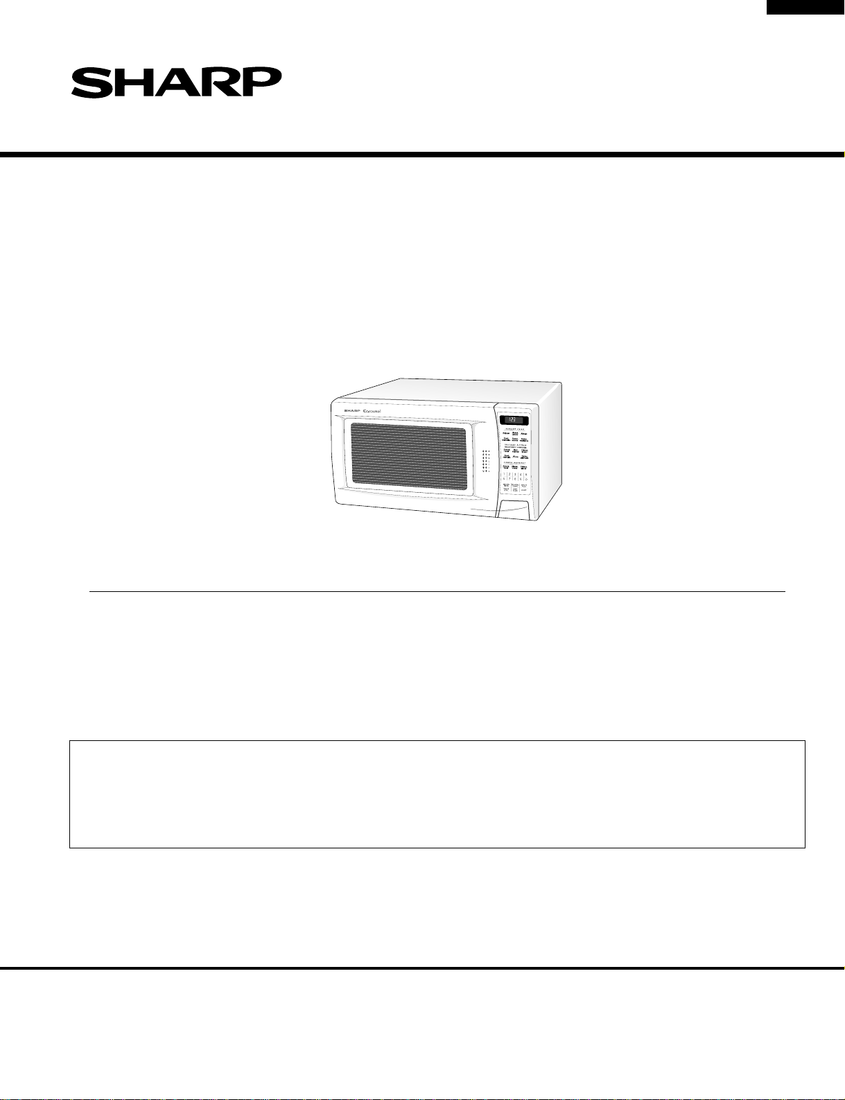
R-320BD
SUPPLEMENTAL SERVICE MANUAL
S5810R320BPD/
MICROWAVE OVEN
MODEL
In the interest of user-safety the oven should be restored to its original condition and only parts identical to those specified
should be used.
WARNING TO SERVICE PERSONNEL: Microwave ovens contain circuitry capable of producing very high
voltage and current, contact with following parts may result in a severe, possibly fatal, electrical shock. (High
Voltage Capacitor, High Voltage Power Transformer, Magnetron, High Voltage Rectifier Assembly, High
Voltage Harness etc..)
R-320BD
This is a supplemental Service Manual for Model R-320BD. This model is quite similar to base
model R-320BB, with only color changing. Use this supplemental manual together with the Base
Model Service Manual (Refer No. is S2805R320BPW/) for complete operation, service information, etc..
This document has been published to be used for after
SHARP CORPORATION
sales service only.
The contents are subject to change without notice.
Page 2

R-320BD
PRECAUTIONS TO BE OBSERVED BEFORE AND
DURING SERVICING TO AVOID POSSIBLE
EXPOSURE TO EXCESSIVE MICROWAVE
ENERGY
(a) Do not operate or allow the oven to be operated with the door open.
(b) Make the following safety checks on all ovens to be serviced before activating the magnetron or other
microwave source, and make repairs as necessary: (1) interlock operation, (2) proper door closing, (3)
seal and sealing surfaces (arcing, wear, and other damage), (4) damage to or loosening of hinges and
latches, (5) evidence of dropping or abuse.
(c) Before turning on microwave power for any service test or inspection within the microwave generating
compartments, check the magnetron, wave guide or transmission line, and cavity for proper alignment,
integrity, and connections.
(d) Any defective or misadjusted components in the interlock, monitor, door seal, and microwave
generation and transmission systems shall be repaired, replaced, or adjusted by procedures described
in this manual before the oven is released to the owner.
(e) A microwave leakage check to verify compliance with the Federal Performance Standard should be
performed on each oven prior to releasing oven to the owner.
BEFORE SERVICING
Before servicing an operative unit, perform a microwave emission check as per the Microwave
Measurement Procedure outlined in this service manual.
If microwave emissions level is in excess of the specified limit, contact SHARP ELECTRONICS
CORPORATION immediately @1-800-237-4277.
If the unit operates with the door open, service person should 1) tell the user not to operate the oven
and 2) contact SHARP ELECTRONICS CORPORATION and Food and Drug Administration's
Center for Devices and Radiological Health immediately.
Service personnel should inform SHARP ELECTRONICS CORPORATION of any certified unit found
with emissions in excess of 4mW/cm2. The owner of the unit should be instructed not to use the unit
until the oven has been brought into compliance.
Page 3
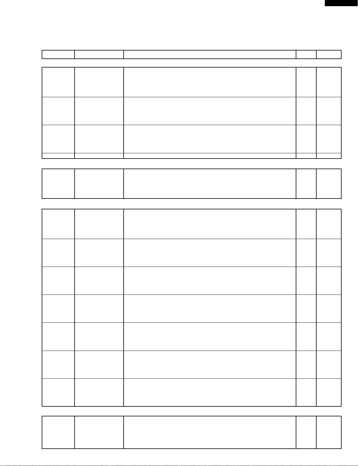
PARTS LIST
Note: The parts marked “∆” may cause undue microwave exposure.
The parts marked “*” are used in voltage more than 250V.
REF. NO. PART NO. DESCRIPTION Q'TY CODE
ELECTRIC PARTS
1- 1 QSW-MA110WRE0 2nd interlock switch / door sensing switch 2 AK
1- 2 QFSHDA009WRE0 Fuse holder 1 AH
1- 3 FFS-BA021WRK0 Monitor fuse and monitor switch assembly 1 AL
1- 3 FFS-BA012WRK0
1- 4 RTHM-A078WRE0 Thermal cut-out 125 deg. 1 AL
1- 5 FACCDA077WRE0 Power supply cord 1 AU
1- 6 FH-DZA083WRK0 High voltage rectifier assembly 1 AQ
*
1- 7 RC-QZA236WRE0 High voltage capacitor 1 AU
*
1- 8 RV-MZA267WRE0 Magnetron 1 BL
∆
*
1- 9 RMOTEA355WRE0 Fan motor 1 AU
1-10 QSOCLA021WRE0 Oven lamp socket 1 AH
1-11 RLMPTA030WRE0 Oven lamp 1 AF
1-12 RMOTDA161WRE0 Turntable motor 1 AU
1-13 RTHM-A048WRE0 Thermal cut-out 170 deg. 1 AH
1-14 RTRN-A569WRE0 Power transformer 1 BP
*
1-15 FDTCTA176WRK0 AH sensor assembly 1 AV
2- 1 GCABUA678WRP0 Outer case cabinet 1 AZ
2- 2 GDAI-A261WRW0 Bottom left plate 1 AP
2- 3 GDAI-A286WRW0 Bottom right plate 1 AN
2- 4 GLEGPA019WRE0 Foot 2 AD
2- 5 GLEGPA067WRF0 Leg 1 AE
3- 1 CPWBFA776WRK0 Power unit 1 BD
3- 1A QCNCMA446DRE0 2-pin connector (CN-A) 1 AC
3- 1B QCNCMA422DRE0 9-pin connector (CN-C) 1 AF
3- 1C FW-VZA196DRE0 2P wire harness (WH-1) 1 AD
3- 1D FW-VZA195DRE0 Switch harness A (SH-A) 1 AD
3- 1E FW-VZA197DRE0 Switch harness B (SH-B) 1 AD
3- 1F LHLD-A171WRF0 LED holder 1 AE
C1 RC-KZA087DRE0 Capacitor 0.1 uF 50V 1 AB
C2 VCEAB31VW108M Capacitor 1000 uF 35V 1 AD
C3 RC-KZA087DRE0 Capacitor 0.1 uF 50V 1 AB
C4-5 VCEAB31VW106M Capacitor 10 uF 35V 2 AB
D1-4 VHD11ES1///-1 Diode (11ES1) 4 AB
D5-8 VHD1SS270A/-1 Diode (1SS270ATA) 4 AA
LD1-5 VHPSLZ381A9-3 Light emitting diode 5 AC
Q1-2 VS2SB1238//-3 Transistor (2SB1238) 2 AA
Q3 VSDTD143ES/-3 Transistor (DTD143ES) 1 AC
R1 VRD-B12EF242J Resistor 2.4k ohm 1/4W 1 AA
R2 VRD-B12HF681J Resistor 680 ohm 1/2W 1 AA
R3 VRD-B12HF511J Resistor 510 ohm 1/2W 1 AB
R4 VRD-B12EF270J Resistor 27 ohm 1/4W 1 AA
R5 VRD-B12EF472J Resistor 4.7k ohm 1/4W 1 AA
R6 VRD-B12EF332J Resistor 3.3k ohm 1/4W 1 AA
RY1 RRLY-A076DRE0 Relay (OMIF-S-124LM) 1 AK
RY2 RRLY-A081DRE0 Relay (VRB24) 1 AL
SP1 RALM-A014DRE0 Buzzer (PKM22EPT) 1 AG
T1 RTRNPA111DRE0 Transformer 1 AP
VRS1 RH-VZA032DRE0 Varistor (10G471K) 1 AE
ZD1 VHEHZ161///-1 Zener diode (HZ16-1) 1 AA
3- 2 DPWBFB753WRK0 CPU unit 1 BD
3- 3 FPNLCB391WRK0 Control panel frame with key unit 1 BB
3- 3-1 FUNTKA883WRE0 Key unit 1 AX
3- 3-2 JBTN-B094WRF0 Open button 1 AG
3- 3-3 MSPRCA050WRE0 Open button spring 1 AB
3- 4 PSHEPA588WRE0 LED sheet 1 AE
3- 5 XEPSD30P08XS0 Screw; 3mm x 8mm 4 AA
4- 1 PCUSUA376WRP0 Cushion 1 AG
4- 2 PPACGA084WRF0 TTM packing 1 AF
4- 3 PHOK-A106WRF0 Latch hook 1 AL
∆
4- 4 LBNDKA099WRW0 Capacitor holder 1 AD
4- 5 NFANJA029WRE0 Fan blade 1 AL
Monitor fuse and monitor switch assembly (Interchangeable)
1AH
CABINET PARTS
CONTROL PANEL PARTS
OVEN PARTS
R-320BD
1
Page 4

R-320BD
REF. NO. PART NO. DESCRIPTION Q'TY CODE
4- 6 PDUC-A652WRP0 Fan duct 1 AU
4- 7 ************* Oven cavity (Not a replaceable part) 1--
∆
4- 8 LANGFA175WRP0 Chassis support 1 AX
4- 9 LANGQA452WRP0 Partition angle 1 AK
4-10 LANGQA492WRP0 MG thermo angle 1 AV
4-11 MLEVPA226WRF0 Switch lever 1 AF
4-12 NCPL-A045WRF0 Coupling 1 AH
4-13 PCUSGA399WRE0 Cushion 1 AF
4-14 PCOVPA275WRE0 Waveguide cover 1 AR
4-15 PCUSGA339WRP0 Cushion 1 AG
4-16 PCUSUA212WRP0 Cushion 1 AB
4-17 LANGTA338WRP0 Sensor mounting angle 1 AP
4-18 GCOVHA385WRF0 Choke cover 1 AG
4-19 PCUSGA385WRP0 Cushion 1 AH
4-20 PCUSUA192WRP0 Cushion 1 AD
4-21 PCUSUA329WRP0 Cushion 1 AC
4-22 PGIDHA058WRP0 MG air guide 1 AE
4-23 PCUSUA126WRE0 Cushion 1 AC
DOOR PARTS
∆
5- 1 FDORFA318WRT0 Door panel 1 BE
5- 2 PSHEPA382WRE0 Sealer film 1 AH
5- 3 GWAKPA582WRR0 Door frame 1 AX
∆
5- 4 HPNL-A694WRR0 Door screen 1 AW
5- 5 LSTPPA139WRF0 Latch head 1 AF
∆
5- 6 MSPRTA187WRE0 Latch spring 1 AC
5- 7 XCPSD40P08000 Screw : 4mm x 8mm 1 AA
5- 8 XCPSD40P08WN2 Screw : 4mm x 8mm 1 AC
MISCELLANEOUS
6- 1 FROLPA079WRK0 Turntable support 1 AQ
6- 2 NTNT-A084WRE0 Turntable tray 1 AQ
6- 3 FW-VZB678WRE0 Main wire harness 1 AW
6- 4 QW-QZA150WRE0 High voltage wire B 1 AF
*
6- 5 PZET-A012WRE0 Terminal insulator 1 AB
6- 6 TCAUAA166WRR0 DHHS caution label 1 AC
6- 7 TCAUAA200WRR0 Monitor caution label 1 AB
6- 8 TINSEA741WRR0 Instruction book 1 AE
6- 9 TCAUAA240WRR0 Screw caution 1 AC
SCREWS,NUTS AND WASHERS
7- 1 XFPSD40P08K00 Screw : 4mm x 8mm 6 AA
7- 2 XHPSD30P06000 Screw : 3mm x 6mm 4 AA
7- 3 XHTSD40P08RV0 Screw : 4mm x 8mm 3 AA
7- 4 XFTSD40P08000 Screw : 4mm x 8mm 4 AA
7- 5 XOTSD40P12RV0 Screw : 4mm x 12mm 7 AA
7- 6 XOTSD40P12000 Screw : 4mm x 12mm 13 AA
7- 7 XOTSE40P08000 Screw : 4mm x 8mm 1 AA
7- 8 LX-CZA070WRE0 Special screw (Torx tamper proof screw) 2 AC
HOW TO ORDER REPLACEMENT PARTS
To have your order filled promptly and correctly, please furnish the following information.
1. MODEL NUMBER 2. REF. NO. 3. PART NO. 4. DESCRIPTION
Order Parts from the authorized SHARP parts Distributor for your area.
Defective parts requiring return should be returned as indicated in the Service Policy.
2
Page 5

R-320BD
1
OVEN AND CABINET PARTS
A
B
4-17
C
1-15
7-2
4-21
D
4-20
4-7
2
4-1
1-11
4-9
1-10
7-5
1-4
3
2-1
7-5
6-7
45
7-5
7-8
7-4
1-8
4-16
1-13
7-2
4-10
4-22
7-6
7-3
6-9
7-3
1-5
6
A
7-5
7-8
B
7-7
C
6-6
7-2
D
E
4-12
4-14
F
G
7-6
2-4
7-6
H
1
2-2
2-5
7-6
2
1-12
7-6
7-6
7-5
4-2
7-5
4-11
7-1
2-3
7-6
2-4
3
4-15
1-1
1-2
4-3
4-19
1-1
1-3
7-5
4-4
4-23
7-1
1-14
4-6
4-13
1-9
1-5
6-1
7-1
7-6
7-6
45
4-5
1-6
1-7
7-1
7-6
4-8
E
7-3
F
6-2
G
H
6
3
Page 6

R-320BD
1
CONTROL PANEL PARTS
A
B
C
2
3 - 3
3-3-1
3-3- 2
3-3-3
3
3-1F
3 - 4
3 - 2
45
3 - 5
3 - 5
3 - 5
DOOR PARTS
3 - 1
6
A
B
C
D
E
5-4
F
G
5-3
5-1
5-6
5-8
5-2
4-18
D
5-7
E
F
5-5
G
6-3
H
Actual wire harness may be different from illustration.
1
2
MISCELLANEOUS
6-4
3
(CAPACITOR)
H
6-5
45
6
4
Page 7

R-320BD
1
A
B
C
2
3
PACKING AND ACCESSORIES
DOOR PROTECTION SHEET
SPADPA204WRE0
6- 8 INSTRUCTION BOOK
& PRINTING MATTER
6- 2 TURNTABLE TRAY
6- 1 TURNTABLE SUPPORT
45
TOP PAD ASSEMBLY
FPADBA341WRK0
CABINET COVER
SPAKHA003WRE0
PLASTIC BAG
SSAKHA034WRE0
BOTTOM PAD ASSEMBLY
FPADBA342WRK0
6
A
B
C
INTO THE
D
E
F
G
OVEN CAVITY
TRAY PACK
SPADFA397WRE0
Not replaceable items.
PACKING CASE
SPAKCD119WRE0
D
E
F
G
H
1
2
3
5
45
H
6
Page 8

R-320BD
COPYRIGHT © 1998 BY SHARP CORPORATION
ALL RIGHTS RESERVED.
No part of this publication may be reproduced, stored in retrieval systems, or transmitted in any form or by any means, electronic, mechanical, photocopying, recording, or otherwise, without prior written permission of the publisher.
'98 SHARP CORP. (2S2.530E) Printed in U.S.A
6
 Loading...