

Page 1
R-209BW
SUPPLEMENTAL SERVICE MANUAL
S6013R209BPW/
MICROWAVE OVEN
EXPRESS MINUTE
DEFROST
SNACKS
POPCORN BEVERAGE
COOKING
BAKED FRESH
POTATO
VEGETABLES
REHEATING
DINNER
PLATE
MODEL
PLUS
In the interest of user-safety the oven should be restored to its original
ROLL,
MUFFIN
condition and only parts identical to those specified should be used.
WARNING TO SERVICE PERSONNEL: Microwave ovens con-
R-209BW
tain circuitry capable of producing very high voltage and
current, contact with following parts may result in a severe,
possibly fatal, electrical shock. (High Voltage Capacitor, High
Voltage Power Transformer, Magnetron, High Voltage Rectifier
Assembly, High Voltage Harness etc..)
This is a supplemental Service Manual for Model R-209BW. This model is quite similar to base
model R-209BK. Use this supplemental manual together with the Base Model Service Manual
(Refer No. is S1803R220BPW/) for complete operation, service information, etc..
TABLE OF CONTENTS
Page
PRECAUTIONS TO BE OBSERVED BEFORE AND DURING SERVICING TO
AVOID POSSIBLE EXPOSURE TO EXCESSIVE MICROWAVE ENERGY ...................INSIDE FRONT COVER
BEFORE SERVICING ......................................................................................................INSIDE FRONT COVER
WARNING TO SERVICE PERSONNEL................................................................................................................1
FOREWORD AND WARNING...............................................................................................................................2
PRODUCT DESCRIPTION....................................................................................................................................3
TEST PROCEDURE ..............................................................................................................................................5
TOUCH CONTROL PANEL ASSEBLY .................................................................................................................7
CONTROL PANEL CIRCUIT ...............................................................................................................................10
PARTS LIST ........................................................................................................................................................11
PACKING AND ACCESSORIES .........................................................................................................................12
SHARP CORPORATION
This document has been published to be used for after
sales service only.
The contents are subject to change without notice.
Page 2

R-209BW
PRECAUTIONS TO BE OBSER VED BEFORE AND
DURING SER VICING TO A VOID POSSIBLE
EXPOSURE TO EXCESSIVE MICROW A VE
ENERGY
(a) Do not operate or allow the oven to be operated with the door open.
(b) Make the following safety checks on all ovens to be serviced before activating the magnetron or other
microwave source, and make repairs as necessary: (1) interlock operation, (2) proper door closing, (3)
seal and sealing surfaces (arcing, wear, and other damage), (4) damage to or loosening of hinges and
latches, (5) evidence of dropping or abuse.
(c) Before turning on microwave power for any service test or inspection within the microwave generating
compartments, check the magnetron, wave guide or transmission line, and cavity for proper alignment,
integrity, and connections.
(d) Any defective or misadjusted components in the interlock, monitor, door seal, and microwave
generation and transmission systems shall be repaired, replaced, or adjusted by procedures described
in this manual before the oven is released to the owner.
(e) A microwave leakage check to verify compliance with the Federal Performance Standard should be
performed on each oven prior to release to the owner.
BEFORE SERVICING
Before servicing an operative unit, perform a microwave emission check as per the Microwave
Measurement Procedure outlined in this service manual.
If microwave emissions level is in excess of the specified limit, contact SHARP ELECTRONICS
CORPORATION immediately @1-800-237-4277.
If the unit operates with the door open, service person should 1) tell the user not to operate the oven
and 2) contact SHARP ELECTRONICS CORPORATION and The Food and Drug Administration's
Center for Devices and Radiological Health immediately.
Service personnel should inform SHARP ELECTRONICS CORPORATION of any certified unit found
with emissions in excess of 4mW/cm2. The owner of the unit should be instructed not to use the unit
until the oven has been brought into compliance.
Page 3
W ARNING TO SER VICE PERSONNEL
Microwave ovens contain circuitry capable of producing very high voltage and current, contact with
following parts
fatal, electrical shock.
(Example)
High Voltage Capacitor, High Voltage Power Trans-
former, Magnetron, High Voltage Rectifier Assembly, High Voltage Harness etc..
Read the Service Manual carefully and follow all
instructions.
may result in a severe, possibly
R-209BW
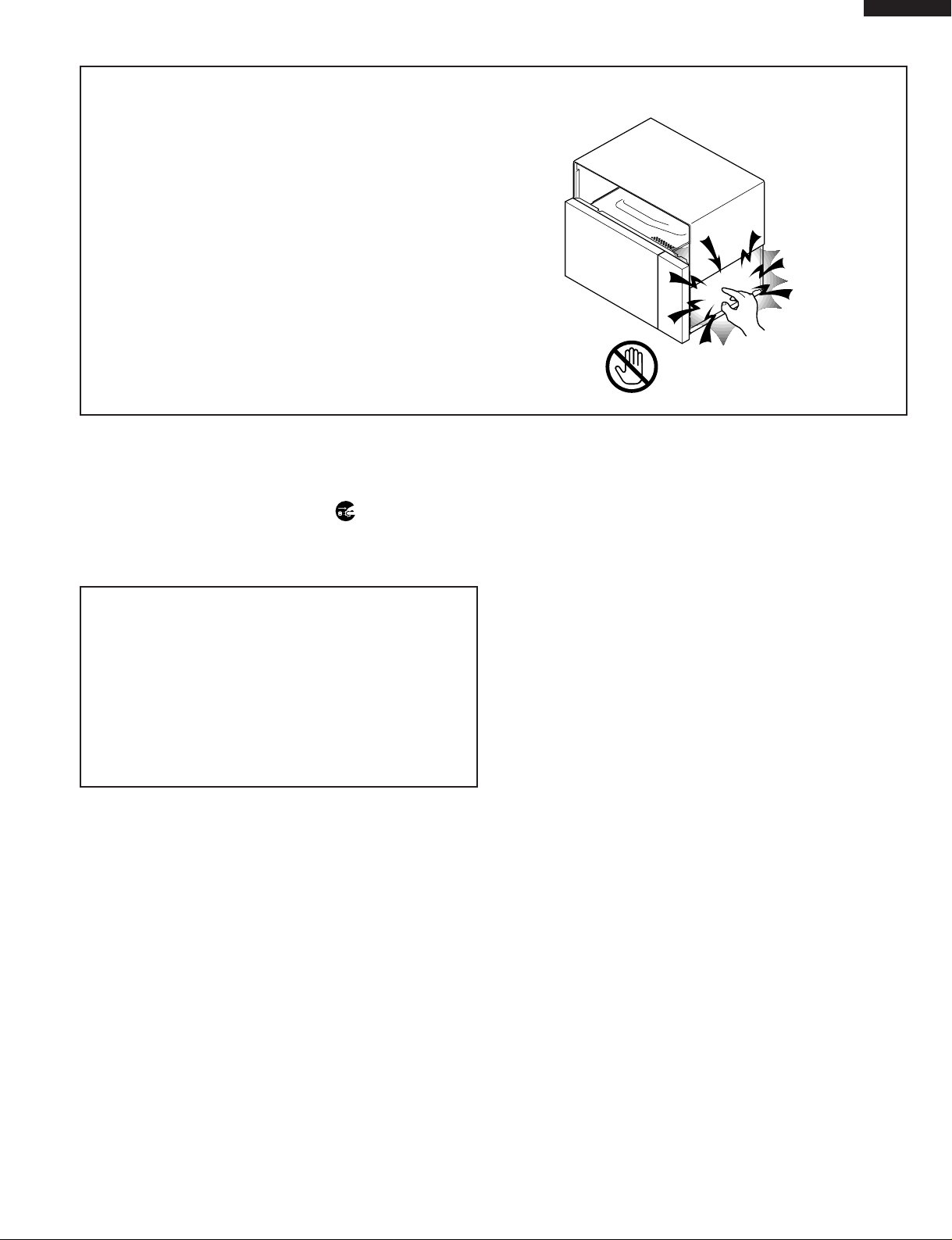
Don't Touch !
Danger High Voltage
Before Servicing
1. Disconnect the power supply cord , and then remove
outer case.
2. Open the door and block it open.
3. Discharge high voltage capacitor.
WARNING:RISK OF ELECTRIC SHOCK.
DISCHARGE THE HIGH-VOLTAGE
CAPACITOR BEFORE SERVICING.
The high-voltage capacitor remains charged about 60
seconds after the oven has been switched off. Wait for 60
seconds and then short-circuit the connection of the highvoltage capacitor (that is the connecting lead of the highvoltage rectifier) against the chassis with the use of an
insulated screwdriver.
Whenever troubleshooting is performed the power supply
must be disconnected. It may, in some cases, be necessary
to connect the power supply after the outer case has been
removed, in this event,
1. Disconnect the power supply cord, and then remove
outer case.
2. Open the door and block it open.
3. Discharge high voltage capacitor.
4. Disconnect the leads to the primary of the power
transformer.
5. Ensure that the leads remain isolated from other
components and oven chassis by using insulation tape.
6. After that procedure, reconnect the power supply cord.
When the testing is completed,
1. Disconnect the power supply cord, and then remove
outer case.
2. Open the door and block it open.
3. Discharge high voltage capacitor.
4. Reconnect the leads to the primary of the power
transformer.
5. Reinstall the outer case (cabinet).
6. Reconnect the power supply cord after the outer case is
installed.
7. Run the oven and check all functions.
After repairing
1. Reconnect all leads removed from components during
testing.
2. Reinstall the outer case (cabinet).
3. Reconnect the power supply cord after the outer case is
installed.
4. Run the oven and check all functions.
Microwave ovens should not be run empty. To test for the
presence of microwave energy within a cavity, place a cup
of cold water on the oven turntable, close the door and set
the power to HIGH and set the microwave timer for two (2)
minutes. When the two minutes has elapsed (timer at zero)
carefully check that the water is now hot. If the water
remains cold carry out Before Servicing procedure and reexamine the connections to the component being tested.
When all service work is completed and the oven is fully
assembled, the microwave power output should be checked
and a microwave leakage test should be carried out.
1
Page 4

R-209BW
SERVICE MANUAL
MICROWAVE OVEN
R-209BW
FOREWORD
This Manual has been prepared to provide Sharp Electronics Corp. Service Personnel with Operation and Service
Information for the SHARP MICROWAVE OVEN, R-209BW.
The model R-209BW is quite similar to base model R-209BK (Refer No. is S1803R220BPW/).
It is recommended that service personnel carefully study the entire text of this manual and the base model's manual so
that they will be qualified to render satisfactory customer service.
Check the interlock switches and the door seal carefully. Special attention should be given to avoid electrical shock and
microwave radiation hazard.
WARNING
Never operate the oven until the following points are ensured.
(A) The door is tightly closed.
(B) The door brackets and hinges are not defective.
(C) The door packing is not damaged.
(D) The door is not deformed or warped.
(E) There is no other visible damage with the oven.
Servicing and repair work must be carried out only by trained service personnel.
DANGER
Certain initial parts are intentionally not grounded and present a risk of electrical shock only during servicing.
Service personnel - Do not contact the following parts while the appliance is energized;
High Voltage Capacitor, Power Transformer, Magnetron, High Voltage Rectifier Assembly, High Voltage
Harness;
If provided, Vent Hood, Fan assembly, Cooling Fan Motor.
All the parts marked “*” on parts list are used at voltages more than 250V.
Removal of the outer wrap gives access to voltage above 250V.
All the parts marked “∆” on parts list may cause undue microwave exposure, by themselves, or when they are
damaged, loosened or removed.
SHARP ELECTRONICS CORPORATION
SHARP PLAZA, MAHWAH,
NEW JERSEY 07430-2135
2
Page 5
PRODUCT DESCRIPTION
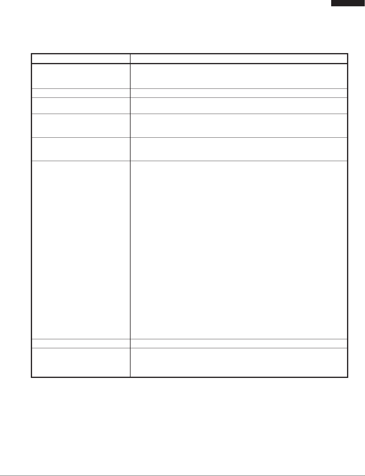
SPECIFICATIONS
ITEM DESCRIPTION
Power Requirements 120 Volts
60 Hertz
Single phase, 3 wire grounded
Power Consumption 1100W / Approx. 9.5 Amperes
Power Output 700 W nominal of RF microwave energy (IEC Test procedure)
Operating frequency 2450 MHz
Case Dimensions Width 18-1/8"
Height 11-3/8"
Depth 14-5/8"
Cooking Cavity Dimensions Width 12-3/8"
(0.7 Cubic feet) Height 7-7/8"
Depth 12-5/8"
Control Complement Touch Control System
Clock (1:00 - 12:59)
Timer (0 - 99 minutes 99 seconds)
Microwave Power for Variable Cooking
Repetition Rate;
P-HI ................................... Full power throughout the cooking time
P-90 .................................................... approx. 90% of FULL Power
P-80 .................................................... approx. 80% of FULL Power
P-70 .................................................... approx. 70% of FULL Power
P-60 .................................................... approx. 60% of FULL Power
P-50 .................................................... approx. 50% of FULL Power
P-40 .................................................... approx. 40% of FULL Power
P-30 .................................................... approx. 30% of FULL Power
P-20 .................................................... approx. 20% of FULL Power
P-10 .................................................... approx. 10% of FULL Power
P-0 ...................................... No power throughout the cooking time
EXPRESS DEFROST pad
MINUTE PLUS pad
Instant Start pads
Number selection pads
TIMER / CLOCK pad
POWER LEVEL pad
START pad
STOP/CLEAR pad
Oven Cavity Light Yes
Safety Standard UL Listed.
FCC Authorized
DHHS RUles, CFR, Title 21, Chapter 1, Subchapter J
R-209BW
3
Page 6

R-209BW
TOUCH CONTROL PANEL
Time display
DEF. LBS. QTY.
ON
EXPRESS MINUTE
DEFROST
POPCORN BEVERAGE
BAKED FRESH
POTATO
DINNER
PLATE
SNACKS
COOKING
VEGETABLES
REHEATING
PLUS
ROLL,
MUFFIN
CHECK
Indicator
SCHEMATIC
NOTE: CONDITION OF OVEN
1. DOOR CLOSED
2. CLOCK APPEARS ON DISPLAY
120V AC
60 Hz
GRN
C/T FUSE
A3
CONTROL UNIT
OL FM
OVEN
LAMP
SECONDARY
INTERLOCK
SWITCH
MAGNETRON
THERMAL CUT-OUT
(RY-1)
TTM
TURNTABLE
MOTOR
A1
COM.
(RY-2)
B1 B2
FAN
MOTOR
PRIMARY
INTERLOCK
RELAY
DOOR
SENSING
SWITCH
N.O.
MONITOR
SWITCH
POWER
TRANSFORMER
CAPACITOR
0.86µF
RECTIFIER
MAGNETRON
Figure O-1. Oven Schematic-Off Condition
4
Page 7

TEST PROCEDURES
R-209BW
PROCEDURE
LETTER
J KEY UNIT TEST
1. Disconnect the power supply cord and then remove outer case.
2. Open the door and block it open.
3. Discharge high voltage capacitor.
4. If the display fails to clear when the STOP/CLEAR pad is depressed, first verify the flat ribbon cable
5. Reconnect all leads removed from components during testing.
6. Re-install the outer case (cabinet).
7. Reconnect the power supply cord after the outer case is installed.
8. Run the oven and check all functions.
COMPONENT TEST
is making good contact, verify that the door sensing switch (stop switch) operates properly; that is the
contacts are closed when the door is closed and open when the door is open. If the door sensing
switch (stop switch) is good, disconnect the flat ribbon cable that connects the key unit to the control
unit and make sure the door sensing switch is closed (either close the door or short the door sensing
switch connecter). Use the Key unit matrix indicated on the control panel schematic and place a
jumper wire between the pins that correspond to the STOP/CLEAR pad making momentary contact.
If the control unit responds by clearing with a beep the key unit is faulty and must be replaced. If the
control unit does not respond, it is faulty and must be replaced. If a specific pad does not respond,
the above method may be used (after clearing the control unit) to determine if the control unit or key
pad is at fault.
G 6 G 5 G 4 G 3 G 2 G 1
G 7
G 8
G 9
BEVERAGE
FRESH
VEGETABLES
ROLL,
MUFFIN
6
3
TIMER
CLOCK
DINNER
2
PLATE
0
MINUTE
PLUS
EXPRESS
45
DEFROST
1
BAKED
POTATO
POWER
LEVEL
STOP
CLEAR
K RELAY TEST
1. Disconnect the power supply cord and then remove outer case.
2. Open the door and blocked it open.
3. Discharge high voltage capacitor.
4. Disconnect the leads to the primary of the power transformer.
5. Ensure that these leads remain isolated from other components and oven chassis by using insulation
tape.
6. After that procedure, re-connect the power supply cord.
7. Remove the outer case and check voltage between Pin No. 3 of the 2 pin connector (A) and the
common terminal of the relay RY2 on the control unit with an A.C. voltmeter.
The meter should indicate 120 volts, if not check oven circuit.
RY1 and RY2 Relay Test
These relays are operated by D.C. voltage
Check voltage at the relay coil with a D.C. voltmeter during the microwave cooking operation.
DC. voltage indicated.....................Defective relay.
DC. voltage not indicated...............Check diode which is connected to the relay coil. If diode
RELAY SYMBOL OPERATIONAL VOLTAGE CONNECTED COMPONENTS
RY1 Approx. 14.6V D.C. Oven lamp / Turntable motor / Cooling fan motor
RY2 Approx. 13.0V D.C. Power transformer
G10
89
is good, control unit is defective.
POPCORN START
7
8. If any abnomal condition is detected, replace the control unit.
9. Disconnect the power supply cord and then remove outer case.
10. Open the door and block it open.
5
Page 8

R-209BW
TEST PROCEDURES
PROCEDURE
LETTER
11. Discharge high voltage capacitor.
12. Reconnect all leads removed from components during testing.
13. Re-install the outer case (cabinet).
14. Reconnect the power supply cord after the outer case is installed.
15. Run the oven and check all functions
M FOIL PATTERN ON THE PRINTED WIRING BOARD TEST
To protect the electronic circuits, this model is provided with a fine foil pattern added to the primary on
the PWB, this foil pattern acts as a fuse.
1. Foil pattern check and repairs.
1) Disconnect the power supply cord and then remove outer case.
2) Open the door and block it open.
3) Discharge high voltage capacitor.
4) Follow the troubleshooting guide given below for repair.
STEPS OCCURRENCE CAUSE OR CORRECTION
1 Only pattern at "a" is broken. *Insert jumper wire J1 and solder.
2 Pattern at "a" and "b" are broken. *Insert the coil RCILF2003YAZZ between "c" and "d".
5) Make a visual inspection of the varistor.
Check for burned damage and examine the
transformer with a tester for the presence of
layer short-circuit (check the primary coil
resistance which is approximately 563Ω ±
10%). If any abnormal condition is detected,
replace the control unit.
COMPONENT TEST
RY1
c
(J1)
a
b
d
1
P
RY2
6) Reconnect all leads removed from components during testing.
7) Re-install the outer case (cabinet).
8) Reconnect the power supply cord after the outer case is installed.
9) Run the oven and check all function.
2. Follow the troubleshooting guide given below, if indicator does not light up after above check and
repairs are finished.
1) Disconnect the power supply cord and then remove outer case.
2) Open the door and block it open.
3) Discharge high voltage capacitor.
4) Disconnect the leads to the primary of the power transformer.
5) Ensure that these leads remain isolated from other components and oven chassis by using
insulation tape.
6) After that procedure, re-connect the power supply cord.
7) Follow the troubleshooting guide given below for repair.
STEPS OCCURRENCE CAUSE OR CORRECTION
The rated AC voltage is not present between
1 Pin No. 3 of the 2-pin connector (A) and the Check supply voltage and oven power cord.
common terminal of the relay RY2.
2 The rated AC voltage is present at primary Low voltage transformer or secondary circuit defective.
side of low voltage transformer. Check and replace control unit.
8) Disconnect the power supply cord and then remove outer case.
9) Open the door and block it open.
6
Page 9

TEST PROCEDURES
R-209BW
PROCEDURE
LETTER
10) Discharge high voltage capacitor.
11) Reconnect all leads removed from components during testing.
12) Re-install the outer case (cabinet).
13) Reconnect the power supply cord after the outer case is installed.
14) Run the oven and check all functions.
TOUCH CONTROL PANEL ASSEMBLY
OUTLINE OF TOUCH CONTROL PANEL
The touch control section consists of the following units as
shown in the touch control panel circuit.
(1) Key Unit
(2) Control Unit
COMPONENT TEST
3) Power Source Circuit
This circuit generates voltage necessary in the control
unit from the AC line voltage. In addition, the synchronizing
signal is available in order to compose a basic standard
time in the clock circuit.
The principal functions of these units and their related
signals are explained below.
Key Unit
The key unit is composed of a matrix, signals generated in
the LSI are sent to the key unit through R00, R01, R02, R03,
R20 and R21.
When a key pad is touched, a signal is completed through
the key unit and passed back to the LSI through R23, K00,
K01 and K02 to perform the function that was requested.
Control Unit
Control unit consists of LSI, ACL circuit, indicator circuit,
power source circuit, relay circuit, buzzer circuit and synchronizing signal circuit.
1) ACL
This circuit generates a signal which resets the LSI to the
initial state when power is supplied.
2) Indicator Circuit
This circuit consists of 4-digits, 12-segments and 3common electrodes using a Liquid Crystal Display.
Symbol Voltage Application
VC -5V LSI(IC1)
4) Relay Circuit
To drive the magnetron, fan motor, turntable motor and
light the oven lamp.
5) Buzzer Circuit
The buzzer is responsive to signals from the LSI to emit
audible sounds (key touch sound and completion sound).
6) Synchronizing Signal Circuit
The power source synchronizing signal is available in
order to compose a basic standard time in the clock
circuit. It accompanies a very small error because it
works on commercial frequency.
7) 2nd. Interlock Relay Control Switch (Door Sensing
Switch)
A switch to “tell” the LSI if the door is open or closed.
7
Page 10

R-209BW
DESCRIPTION OF LSI
The I/O signal of the LSI are detailed in the following table.
Pin No. Signal I/O Description
1 RESET IN Auto clear terminal.
Signal is input to reset the LSI to the initial state when power is supplied. Temporarily
set to “L” level the moment power is supplied, at this time the LSI is reset. Thereafter
set at “H” level.
2 TEST IN Connected to GND.
3 VSS IN Power source voltage: -5V.
VSS voltage of power source circuit input. Connected to VC.
4 OCS3 IN Internal clock oscillation frequency setting input.
The internal clock frequency is set by inserting the resistor oscillation circuit with
respect to OCS4 terminal.
5 OCS4 OUT Internal clock oscillation frequency control output.
Output to control oscillation input of OCS3.
6 VD1 IN Power source for oscillation circuit.
7 VDD IN Power source voltage input terminal.
Connected to GND.
8 AVDD IN A/D converter power source voltage.
The power source voltage to drive the A/D converter in the LSI. Connected to GND.
9 AVREF IN A/D converter power source voltage.
The power source voltage to drive the A/D converter in the LSI. Connected to GND.
10 AVSS IN Power source voltage: -5V.
AVSS voltage of power source circuit input. Connected to VC.
11-13 P40-P42 IN Terminal to change functions according to the Model.
By using the A/D converter contained in the LSI, DC voltage in accordance with the
Model in operation is applied to set up its function.
14 P43 IN To input signal which communicates the door open/close information to LSI.
Door close “H” level signal (0V). Door open “L” level (-5V).
15 BZ OUT Signal to sound buzzer (2.0 kHz).
A: key touch sound.
B: Completion sound.
0.1 sec.
A
2.0 sec.
B
H : GND
L : -5V
H : GND
L : -5V
16 R00 OUT Key strobe signal.
Signal applied to touch-key section. A pulse signal is input to P23, K00, K01 and K02
terminal while one of G6 line keys on key matrix is touched.
17 R01 OUT Key strobe signal.
Signal applied to touch-key section. A pulse signal is input to P23, K00, K01 and K02
terminal while one of G5 line keys on key matrix is touched.
18 R02 OUT Key strobe signal.
Signal applied to touch-key section. A pulse signal is input to P23, K00, K01 and K02
terminal while one of G4 line keys on key matrix is touched.
19 R03 OUT Key strobe signal.
SigM nal applied to touch-key section. A pulse signal is input to P23, K00, K01 and K02
terminal while one of G3 line keys on key matrix is touched.
20 P20 OUT Key strobe signal.
Signal applied to touch-key section. A pulse signal is input to P23, K00, K01 and K02
terminal while one of G2 line keys on key matrix is touched.
21 P21 OUT Key strobe signal.
Signal applied to touch-key section. A pulse signal is input to P23, K00, K01 and K02
terminal while one of G1 line keys on key matrix is touched.
22 P22 OUT Terminal not used.
8
Page 11

Pin No. Signal I/O Description
GND
-5V
16.7 msec.
23 P23 IN Signal similar to K02.
When either G7 line on key matrix is touched, a corresponding signal will be input into P23.
24 K00 IN Signal similar to K02.
When either G8 line on key matrix is touched, a corresponding signal will be input into K00.
25 K01 IN Signal similar to K02.
When either G9 line on key matrix is touched, a corresponding signal will be input into K01.
26 K02 IN Signal coming from touch key.
When either G10 line on key matrix is touched, a corresponding signal out of R00, R01,
R02, R03, P20 and P21 will be input into K02. When no key is touched, the signal is
held at “H” level.
27 K03 IN Signal synchronized with commercial power source frequency.
This is the basic timing for time processing of
LSI.
28 COM0 OUT Common data signal: COM1.
Connected to LCD (Pin No. C1)
29 COM1 OUT Common data signal: COM2.
Connected to LCD (Pin No. C2)
30 COM2 OUT Common data signal: COM1.
Connected to LCD (Pin No. C3)
31 COM3 OUT Terminal not used.
32-33 SEG0-SEG1 OUT Terminal not used.
34 SEG2 OUT Magnetron high-voltage circuit driving signal.
To turn on and off the cook relay (RY2). The
signals holds “L” level during microwave
cooking and “H” level while not cooking. In
other cooking modes (variable cooking) the
signal turns to “H” level and “L” level in
repetition according to the power level.
100P
70P
OFF
OFF
ON
ON
24 sec.
35 SEG3 OUT Terminal not used.
36 SEG4 OUT Oven lamp, fan motor and turntable motor driving signal.
To turn on and off shut off relay (RY1). The
16.7 msec.
square waveform voltage is delivered to the
RY1 driving circuit and RY2 control circuit.
During cooking
OFF
8 sec.
R-209BW
H : GND
L : -5V
H : GND
L : -5V
H : GND
L : -5V
37-39 SEG5-SEG7 OUT Terminal not used.
40-51 SEG8-SEG19 OUT Segment data signal.
Connected to LCD.
The relation between signals are as follows:
LSI signal (Pin No.) LCD (Pin No.) LSI signal (Pin No.) LCD (Pin No.)
SEG 8 (40) .......................... S12 SEG 14 (46)............................. S6
SEG 9 (41) .......................... S11 SEG 15 (47)............................. S5
SEG 10 (42) .......................... S10 SEG 16 (48)............................. S4
SEG 11 (43) ............................ S9 SEG 17 (49)............................. S3
SEG 12 (44) ............................ S8 SEG 18 (50)............................. S2
SEG 13 (45) ............................ S7 SEG 19 (51)............................. S1
52-53 VC1-VC2 IN Power source voltage input terminal.
Standard voltage for LCD.
54 VC3 OUT Terminal not used.
9
Page 12

R-209BW
1
A
LIQUID CRYSTAL DISPLAY
ON DEF. LBS QTY. CHECK
B
GND
C
2
C 3
C 2
C 1
S 1
S 2
S 3
S 4
S 5
S 6
S 7
S 8
S 9
S10
S11
S12
44
SEG12
SEG11
SEG10
4554
SEG13
SEG14
SEG15
SEG16
SEG17
SEG18
SEG19
VC1
VC2
VC3
C6
/25v
0.01µ
C5 0.1µ/25v
0.1µ/25v
R6 15k
VSS
TEST
1
RESET
SEG9
OCS3
SEG8
OCS4
SEG7
VD1
SEG6
VDD
C7
SEG5
SEG4
IC1
AVDD
AVREF
0.1µ
3
/25v
SEG3
AVSS
SEG2
SEG1
P40
SEG0
P41
COM3
P42
COM2
P43
30
COM1
COM0
K03
K02
K01
K00
P23
P22
P21
P20
R03
R02
R01
R00
B Z
15 29
14
C4
R50 20kF
(J15) 4.7k
(J11) 4.7k
(J14)
(J10)
(J13) 4.7k
(J12)
R20 15k
2SA1037AK
HZ4C3
ZD1
C3 0.01µ/25v
VC
C11 0.01µ/25v
R10 15k
Q1
1k
R5
CPU UNIT
D
45
15k
R62
STOP
CLEAR
LEVEL
START
G 6 G 5 G 4 G 3 G 2 G 1
POWER
PLUS
MINUTE
EXPRESS
4
PLATE
DINNER
2
5
6
3
FRESH
BEVERAGE
G 8
G 7
BAKED
POTATO
DEFROST
POPCORN
1
7
0
8
9
TIMER
CLOCK
ROLL,
MUFFIN
VEGETABLES
G 9
G10
KEY UNIT
15k
R63
15k
R64
15k
R65
15k
R66
15k
R67
C60 330p/50v
C61 330p/50v
C62 330p/50v
C63 330p/50v
R75 100k
R76 100k
R77 100k
R78 100k
R70 15k
R71 15k
R72 15k
R73 15k
6
A
B
C
D
C40 0.01µ/25v
C20
0.1µ
/25v
/25v
0.1µ
C10
Q10 DTA143EKA
E
GND
C8 47µ/16v
–
+
R4
910 1/2w
C1 0.1µ/50v
VR
POWER UNIT
C2 470µ/25v
–
F
D3
D1-D4
11ES1
D1
G
T1
+
D4
D2
d
3.3k 1/4w
R30
PKM22EPT
SP1
Q30 DTA143EKA
RY1
Q20
DTA143EKA
Q21
DTD143ES
D20
C21 10µ/35v
–
+
Q22
DTA143ES
D21
RY2
R40 4.7k
D22
R41 15k
D40
: IF NOT SPECIFIED, 1/10W ± 5%
NOTE : IF NOT SPECIFIED, 1SS270A
Figure S-3. CPU Unit Circuit
E
F
G
(J1)
VRS1 10G471K
c
ab
FAN MOTOR
NO
MICRO
B 2
GND
B 1
DOOR
SENSING
COM
AC(H)
45
H
6
A 3
A 1
H
AC(N)
AC120V
60Hz
1
2
OVEN LAMP
TURNTABLE
MOTOR
3
10
Page 13

PARTS LIST
Note: The parts marked “∆” may cause undue microwave exposure.
The parts marked “*” are used in voltage more than 250V.
REF. NO. PART NO. DESCRIPTION Q'TY CODE
ELECTRIC PARTS
1- 1 QSW-MA131WRE0 Secondary interlock switch & door sensing switch 2 AG
1- 2 FFS-BA020WRK0
1- 3 FACCDA064WRE0 Power supply cord 1 AP
1- 4 QSOCLA021WRE0 Oven lamp socket 1 AH
1- 5 FH-DZA081WRK0 High voltage rectifier 1 AQ
*
1- 6 RC-QZA228WRE0 High voltage capacitor 1 AT
*
1- 6 RC-QZA201WRE0 High voltage capacitor (Interchangeable) 1 AW
*
1- 7 RMOTEA355WRE0 Fan motor 1 AU
1- 7 RMOTEA338WRE0 Fan motor (Interchangeable) 1 AV
1- 8 RV-MZA226WRE0 Magnetron 1 BE
∆
*
1- 8 RV-MZA282WRE0 Magnetron (Interchangeable) 1 BP
∆
*
1- 9 RLMPTA030WRE0 Oven lamp 1 AF
1-10 RMOTDA186WRE0 Turntable motor 1 AW
1-10 RMOTDA211WRE0 Turntable motor (Interchangeable) 1 AS
1-11 RTHM-A078WRE0 Thermal cut-out 125˚C 1 AK
1-12 RTRN-A561WRE0 Power transformer 1 BM
*
2- 1 GCABUA696WRP0 Outer case cabinet 1 AF
2- 2 GDAI-A304WRW0 Bottom plate 1 AF
2- 3 GLEGPA074WRE0 Foot 2 AC
3- 1 DPWBFB972WRU0 Control unit 1 BA
3- 2 FPNLCB512WRKZ Control panel frame with key unit and LCD 1 BA
3- 2-1 FUNTKB008WREZ Key unit 1 AV
3- 2-2 RLCDSA045DRE0 Liquid crystal display 1 AM
3- 3 QCNC-A012WRE0 Rubber connector 1 AF
3- 4 XEPSD30P08XS0 Screw; Control unit mtg. 3 AA
4- 1 PHOK-A105WRF0 Latch hook 1 AL
∆
4- 2 LANGQA477WRW0 Light mount plate 1 AY
4- 3 PCUSUA502WRP0 Waterproof cushion 1 AD
4- 4 LBNDKA038WRP0 Capacitor holder 1 AF
4- 5 NFANJA029WRE0 Fan blade 1 AL
4- 6 PDUC-A694WRF0 Fan duct 1 AG
4- 7 ************* Oven cavity (Not replaceable part) 1--
∆
4- 8 GLEGPA073WRF0 Leg 1 AD
4- 9 LANGTA318WRP0 Chassis support 1 AE
4-10 PCUSGA389WRP0 Cushion 1 AG
4-11 PCOVPA276WRE0 Waveguide cover 1 AM
4-12 PCOVPA342WRF0 B-cover Right 1 AH
4-13 PCOVPA343WRF0 B-cover Left 1 AH
4-14 PCUSUA443WRP0 Cushion 2 AE
4-15 PDUC-A700WRF0 Air separator 1 AN
4-16 PPACGA097WRE0 O-ring 1 AG
4-17 PCUSUA474WRP0 Cushion 1 AC
∆
5- 1 FDORFA321WRT0 Door panel 1 AT
5- 2 GWAKPA628WRF0 Door frame 1 AY
5- 3 HPNL-A738WRRZ Door screen 1 AS
∆
5- 4 LSTPPA175WRF0 Latch head 1 AE
5- 5 MSPRTA084WRE0 Latch spring 1 AB
5- 6 PSHEPA622WRE0 Sealer film 1 AG
5- 7 GCOVHA390WRF0 Choke cover 1 AK
5- 8 XCPSD40P08000 Screw : 4mm x 8mm 4 AA
6- 1 FROLPA089WRK0 Turntable support 1 AP
6- 1 FROLPA090WRK0 Turntable support (Interchangeable) 1 AQ
6- 2 NTNT-A094WRE0 Turntable 1 AN
6- 3 TINSEA852WRRZ Instruction book 1 AD
6- 4 FW-VZB657WRE0 Switch harness 1 AH
6- 5 FW-VZB658WRE0 Main wire harness 1 AV
*
C/T fuse (13A, 120˚C) & monitor switch (V-16G-2C25-L(R)) assembly
1AP
CABINET PARTS
CONTROL PANEL PARTS
OVEN PARTS
DOOR PARTS
MISCELLANEOUS
R-209BW
11
Page 14

R-209BW
REF. NO. PART NO. DESCRIPTION Q'TY CODE
6- 6 QW-QZA150WRE0 High voltage wire B 1 AF
6- 7 TCAUAA166WRR0 DHHS caution label 1 AC
6- 8 TCAUAA156WRR0 User caution label 1 AF
6- 9 TCAUAA239WRR0 Monitor caution 1 AC
6-10 TCAUAA253WRR0 Earth caution 2 AC
6-11 TCAUAA240WRR0 Screw caution 1 AC
6-12 TLAB-A183WRR0 Service label 1 AB
SCREWS AND WASHERS
7- 1 XHPSD40P08K00 Screw : 4mm x 8mm 5 AA
7- 2 LX-EZA042WRE0 Special screw 2 AB
7- 3 LX-WZA028WRE0 Special washer 1 AB
7- 4 LX-CZA078WRE0 Special screw 2 AC
7- 5 XHTSD40P08RV0 Screw : 4mm x 8mm 5 AA
7- 6 XHPSD30P06000 Screw : 3mm x 6mm 1 AA
7- 7 LX-CZ0052WRE0 Special screw 2 AA
7- 8 XOTSD40P12000 Screw : 4mm x 12mm 6 AA
7- 9 XOTSE40P08000 Screw : 4mm x 8mm 4 AA
7-10 LX-CZA071WRE0 Special screw (Torx tamper proof screw) 2 AC
7-11 LX-CZA073WRE0 Special screw 2 AC
7-12 LX-CZA076WRE0 Special screw 1 AC
HOW TO ORDER REPLACEMENT PARTS
To have your order filled promptly and correctly, please furnish the following information.
1. MODEL NUMBER 2. REF. NO. 3. PART NO. 4. DESCRIPTION
Order Parts from the authorized SHARP parts Distributor for your area.
Defective parts requiring return should be returned as indicated in the Service Policy.
PACKING AND ACCESSORIES
DOOR PROTECTION SHEET
SPADPA580WRE0
6-3 INSTRUCTION BOOK
6-2 TURNTABLE TRAY
MICROWAVE OVEN
TOP PAD ASSEMBLY
FPADBA387WRK0
POLYETHYLENG BAG
SSAKHA014WRE0
BOTTOM PAD ASSEMBLY
FPADBA388WRK0
INTO THE
OVEN CAVITY
TRAY PAD ASSY
(CPADBA244WRK0)
6-1 TURNRABLE SUPPORT
12
Not replaceable items.
PACKING CASE
FPAK-A341WRKZ
Page 15

R-209BW
1
OVEN AND CABINET PARTS
A
1-4
B
C
D
4-3
4-2
4-17
4-14
4-7
6-12
4-11
2
1-2
1-9
7-8
6-9
4-14
7-9
3
45
6
7-11
7-10
2-1
7-11
A
7-10
B
7-1
1-8
7-9
C
6-7
6-10
7-12
4-5
6-10
1-3
4-6
7-5
7-5
D
7-5
A
A
6-11
1-7
7-1
1-6
7-8
E
4-9
F
E
6-2
7-3
4-16
7-7
1-11
7-6
4-4
1-5
1-10
1-12
4-10
4-1
1-1
1-2
1-1
4-8
7-2
F
6-1
7-1
4-15
2-2
G
7-4
G
2-3
4-13
7-8
H
7-8
2-3
4-12
7-4
H
7-8
1
2
3
45
6
13
Page 16

R-209BW
1
A
Before attaching Control unit to
Control panel, foil side of Control
2
3
45
6
A
unit must be cleaned by ethylalcohol.
B
3-2
3-2-2
3-1
3-3
CONTROL PANEL PARTS
3-4
DOOR PARTS
B
5-6
5-8
6-8
C
D
3-2-1
5-2
5-1
5-7
C
D
5-8
5-3
E
E
5-4
F
5-5
F
MISCELLANEOUS
G
6-4
Actual wire harness may be different than illustration.
H
1
2
3
45
6-5
G
6-6
H
6
COPYRIGHT © 2000 BY SHARP CORPORATION
ALL RIGHTS RESERVED.
No part of this publication may be reproduced, stored in retrieval systems, or transmitted in any form or by any means, electronic, mechanical, photocopying, recording, or otherwise, without prior written permission of the publisher.
14
2000SHARP CORP. (6S2.530E) Printed in U.S.A
 Loading...